5100 series, catalog 5170 quad-ethernet module · 5100 series, catalog 5170 . quad ... transfer...
TRANSCRIPT
Installation Manual
381333-443 D 50 Hanover Rd, Florham Park, NJ 07932-1591 USA Call 1 800 800-2726 (ASC0) for sales or service www.ascopower.com
5100 Series, Catalog 5170 Quad-Ethernet Module
Accessory 72EE2 for ASCO 4000 & 7000 Series Transfer Switches (Group 5 controller) & 5200 Series Power Metering
Section Page
1 Introduction Purpose of this Manual .................................................................................... 1-1 General Specifications ..................................................................................... 1-1
2 Access Levels and Passwords Access and Passwords ................................................................................... 2-1 Addresses ........................................................................................................ 2-1
3 Webpage Interface User Requirements ......................................................................................... 3-1 Getting Connected to the QEM over the Ethernet .......................................... 3-1 Webpage Design and Navigation ................................................................... 3-2
4 Modbus & ASCOBusII TCP Interfaces Modbus TCP Interface ..................................................................................... 4-1 ASCOBusII TCP Interface ............................................................................... 4-1
5 SNMP Interface SNMP Configuration and Interface ................................................................. 5-1
6 Email (SMTP) Interface SMTP Configuration and Interface ................................................................. 6-1
7 5170 QEM Configuration Details Configuration → Edit Mode ............................................................................ 7-1 Firmware Upgrade .......................................................................................... 7-2
Appendix Troubleshooting ............................................................................................... A-1 Types of Data/Control ...................................................................................... A-2 Glossary........................................................................................................... A-3 Communication Address Form ............................................................ in the back
Index ................................................................................................................ back page


5170 Quad-Ethernet Module Introduction 1-1
Introduction
The ASCO Catalog 5170 Quad-Ethernet Module (QEM) is a stand-alone Ethernet switch and data concentrator. It allows users to communicate with the new family of devices made by ASCO Power Technologies over a local area network (LAN) or over a secure Internet connection. If the 5170 QEM is provided on an ASCO 4000 or 7000 Series Transfer Switch, it is designated as Accessory 72EE2. Purpose of this Manual
This manual should be used to assist individuals who:
▪ will install and configure the 5170 QEM ▪ will monitor / control devices made by ASCO Power Technologies by using the 5170 QEM’s built-in web pages ▪ will communicate with ASCO Power Technologies products through the 5170 QEM by using a Modbus TCP-based monitoring system (BMS or SCADA) ▪ will capture / read data from the 5170 QEM by using SNMP For specific LAN details contact the LAN administrator or IT specialist. If the 5170 QEM is provided as Acc. 72EE2 on an ASCO 4000 or 7000 Series transfer switch, refer to the transfer switch installation manual, Group 5 controller user’s guide, and wiring diagram. General Specifications
Voltage: 24 V dc Power Requirements: 1.7 W Mounting: DIN mount vertical Dimensions (L,H,W): 4” x 5” x 2” (4 cm, 11 cm, 10 cm) Ambient Temperature: -4° F to 158° F(-20° C to +70° C) Ports: 2 (yellow stripe) for ASCO devices (APAC-future) 2 (purple stripe) for ASCO devices (TTL) 4 (blue stripe) for Ethernet J4 (green stripe on the top) for RS485 Installation
The 5170 QEM mounts on a standard 35 mm DIN rail (not supplied). To release it from the DIN rail, pull down on the handle at the bottom. A power terminal plug is provided. Connect the device(s) from ASCO Power Technologies to the upper ports (purple stripe). Connect the Ethernet network to the lower ports (blue ports). Use Category 5e or higher cable with RJ-45 connectors.
Tip Communication Address form is included at the back to help you fill in needed information on your QEM.
The 5170 Quad-Ethernet Module provides Ethernet-access that allows users to view data from 4000 or 7000 Series automatic transfer switches and 5200 Series Power Metering. All users must follow these precautions:
To avoid possible shock, burns, or death, de-energize all electrical sources to the Transfer Switch before installing the 5170 Quad-Ethernet Module. Be sure that Users to whom you give access are those persons that you want to view information about the electrical system.
Windows and Internet Explorer are registered trademarks of Microsoft Corporation.
NOTICE
DANGER !

5170 Quad-Ethernet Module Access Levels and Passwords 2-1
Access Levels and Passwords
The 5170 QEM has three different levels of web page user access. The importance of these levels varies based on the interface method that is selected. The 5170 QEM is shipped with three preset usernames and default passwords. The three usernames cannot be changed. All three passwords can be changed by the admin level user. All three users (monitor, control, admin) can change their own password. The 5170 QEM default password must be changed upon the first login. The Change User Password screen appears. The new password must be 4 to 15 characters, and a combination of a-z, A-Z, and 0-9. If a user enters a wrong password three times, that username is locked out for one minute.
Username (lower case)
cannot be changed
Access Level
Default Password
(upper case) Write the new Password
here ↓
monitor View access: can view status and webpages, cannot transfer or retransfer load, or make setting changes. Can change monitor password.
ASCO
control Control access: can transfer and retransfer load (ATS), cannot change any configuration settings. Can change control password.
ASCO
admin Full access: can set passwords and change all configuration settings of the 5170 QEM.
ASCO
Be sure that users to whom you give control access are those persons that you want to be able to control the electrical system.
How to change a password Click the Configuration tab, click Ethernet Module, then Edit. Login again, click the Advanced tab, then Change User Password. In the Change User Password window, type the Username (admin), the Old password, the New password, and Confirm new password. Then click Save, and a message should indicate that the password was changed.
Figure 2-1. Change password screen. Addresses The MAC address and the default IP address are located on the outside of the 5170 QEM. Refer to the About webpage for determining the IP address and MAC address.
Address Default Address New Address IP Address 169.254.001.001
MAC Address 00:0C:99:____:____:____. The MAC Address cannot be changed by the user
NOTICE
Type monitor, control, or admin (lower case).

5170 Quad-Ethernet Module Webpage Interface 3-1
Figure 3-1. Login screen.
Webpage Interface
The 5170 QEM has built-in web pages that allow the user to monitor and control the downstream capable devices made by ASCO Power Technologies. A computer (or any web-enabled product, including smart phones and tablets) and a connection to the 5170 QEM over Ethernet will give the user access to data. User Requirements
• The user has a computer or web-enabled device that has been configured to communicate over a network to the 5170 QEM. The most common web-enabled device would be a computer and the most common network connection would be over a LAN (local area network). The setup and testing of this network can be viewed in the Configuration area of this manual.
• The user has been provided the IP address of the 5170 QEM as well as a User Name and Password for access. It is possible that the information is still the default settings but may have been changed during setup.
• The user’s web browser needs to be one supported by the 5170 QEM. The 5170 QEM supports most web browsers but was designed for Internet Explorer 9.0 or higher.
Getting Connected to the 5170 QEM over the Ethernet Open the web browser of the web-enabled device that will be used to view the 5170 QEM web pages. The default IP address is 169.254.1.1. Type the correct IP address in the address bar and press Enter. See Figure 3-1. The webpage should show a Login page. If the webpage appears it indicates that all of the network configurations were done correctly. If the Login page is not displayed, the setup needs to be reviewed. Common causes for not being able to connect to the 5170 QEM could be: It is not powered on, duplicate IP address, cables not connected, or gateway address/network settings. Also refer to the troubleshooting section. Type the User ID and Password and click Login. Refer to page 2-1. When a correct username and password is entered the dashboard page should appear.
Figure 3-2. Dashboard page (typical for 4000 & 7000 Series Transfer Switch with Acc. 72EE2)

3-2 Webpage Interface 5170 Quad-Ethernet Module Webpage Design and Navigation The web pages provide easy movement between pages. Tabs with drop-down boxes at the top allow navigation between pages. Navigation is typically one-level deep. Figure 3-3 shows the navigation bar and drop-down boxes.
Figure 3-3. Navigation bar and drop-down boxes.
▪ The Dashboard page displays dynamic data for each device; they update every second.
Transfer Switch (TS) If the 5170 QEM is an Acc. 72EE2 on a 4000 or 7000 Series Transfer Switch, the device is Transfer Switch. Click Dashboard to display the transfer switch status, voltage and frequency, activity, statistics, alerts, time delays, and identification. The load can be transferred or retransferred via the Controls area of the page (requires control or admin access level).
NOTE The remote transfer feature must be enabled in configuration/Ethernet module configuration page.
Power Meter If the 5170 QEM is used with a 5210 Digital Power Meter or 5220 Power Manager, the device is Power Meter. (Normal, Emergency, Load on a transfer switch or Other for stand-alone applications) Click Power Meter to display the source status, voltage and frequency, activity, statistics, alerts, time delays, and identification.
NOTE To display connected meter data, the number of Power Meters has to be selected in Configuration/Ethernet Module, TCP/IP MODBUS PARAMETERS, Meter Connected ▪ The Events page shows event information captured from the ASCO devices (transfer switch controller), if supported. It shows in log number order, the date and time, type, and cause of each event. ▪ The Details pages generally show data or settings information for each device.
Transfer Switch Controller If the 5170 QEM is an Acc. 72EE2 on a 4000 or 7000 Series Transfer Switch, the device is a Transfer Switch. Click Transfer Switch Controller to display a page similar to the Dashboard page. It has additional data.
Power Meter If the device is a Digital Power Meter or Power Manager (Norm, Emer, Load), click Power Meter to display a page similar to the Dashboard page. It has additional data.
▪ The Configuration pages are of three types: Ethernet settings, Transfer Switch Controller, Metering Device Settings, and the users can upgrade the 5170 QEM firmware. ▪ The About page shows all of the devices possible and displays detailed device identification.
If the 5170 QEM is an Acc. 72EE2on a 4000 or 7000 Series Transfer Switch, one device is the transfer switch Controller (Group 5).
▪ Particular web pages, or the data of those pages, will be dependent on the devices connected to the 5170 QEM.
Dashboard Events Details Configuration About
TS Controller
Ethernet Module
TS Controller
TS Controller
Power Meter
Power Meter

5170 Quad-Ethernet Module Modbus & ASCOBusII TCP Interfaces 4-1
TCP/IP Modbus (for Monitoring Systems)
The 5170 QEM can act as a Modbus server to provide data to a Modbus client on demand over TCP/IP Intranet. The 5170 QEM looks transparent to the Modbus client. The Modbus register in the downstream device looks like it is inside the 5170 QEM. Because the 5170 QEM acts as a data concentrator, the data from downstream devices is constantly updated and available in the 5170 QEM. This design results in a very fast turn-around time.
To be able to control a Transfer Switch (TS), you need to set up a password. Configuration → Ethernet Module → Edit → Login Password. From Advanced, click Modbus Control Password.
Accessing Modbus Data
Accessing parameters by Modbus requires three components over TCP/IP: the IP Address, the TCP Port device address, and the Modbus Register number. Modbus is always enabled in the 5170 QEM.
IP Address The IP Address required to allow a master the ability to communicate to the 5170 QEM is defined in the configuration pages of the 5170 QEM web server, ETHERNET TCP/IP v4 BLOCK. The Modbus/TCP Client is on the same network as the Modbus/TCP server (the 5170 QEM).
Device Address The 5170 QEM maps the Modbus data using an alias table to define must be device addressing. This is the device address needed when configuring the Modbus client. This address can be accessed from the Configuration → Ethernet Module page of the 5170 QEM webpage, TCP/IP MODBUS PARAMETER BLOCK.
The Modbus address for Group 5 controller and 5200 Series Meter as configured in the 5170 QEM as 1 and 2 respectively.
Note The Meter Connected setting is set to zero. This means that MODBUS communication over TCP for the Power Meter is disabled even though there was a assigned address of 2. To enable this, set meter connected value to 1.
Modbus Register The Modbus register map is the same as that of the downstream device. As an example, the line-to-line voltage (A-B) of the 4000 &7000 Transfer Switch’s Group 5 Controller is at register address 40017. Reading this same register from the 5170 QEM will provide the data from the Group 5 Controller to the Modbus client.
The TCP port setting is done on the Configuration/Ethernet Module page, ETHERNET TCP/IPv4 BLOCK. The port is defaulted to 10001. For an example interface using the Modbus Test Suite refer to document 381339-319.
NOTE The Modbus and ASCOBus II protocols use the same port address
ASCOBusII / TCP Interface
ASCOBusII is a proprietary protocol designed by ASCO Power Technologies for use with ASCO 5700 & 5900 Series CPMS systems. Accessing ASCOBusII data requires an ASCO Power Technologies technician. ASCOBus II is always enabled in the 5170 QEM and cannot be disabled.
The downstream Group 5 Controller and Series 5200 Meter (when present) must both be configured to be ASCOBusII, 19200 baud and both assigned as address 1 regardless of the (upstream) Ethernet protocols being used. These settings CAN NOT be changed from the 5170 QEM webpages.
NOTICE

5170 Quad-Ethernet Module SNMP Interface 5-1
SNMP Interface
The Simple Network Management Protocol (SNMP) was created as a way to monitor and manage network devices and hosts. SNMP is mostly a tool for network managers. Because of its simplicity it has also been used as a way to monitor other devices (like the 5170 QEM). SNMP by default is disabled. To use, it has to be enabled. A Management Information Base (MIB) file allows a SNMP client the ability to understand the structure and availability of the managed data in a network device (in this case, the 5170 QEM). 5170 QEM Support The 5170 QEM acts as a SNMP agent, providing data to a SNMP Manager on demand. The 5170 QEM supports the GET, GETNEXT, GETBULK,
TRAP, and RESPONSE commands (SNMP v1 and v2). The 5170 QEM does not support the SET or INFORM commands and it does not support SNMP v3. SNMP Configuration and Interface To enable SNMP functionality in the 5170 QEM, go to the Configuration → Edit Mode web page. Click the box. Figure 5-1 shows all the parameters that need to be filled-out to fully enable SNMP in 5170 QEM. You can configure a maximum of three (3) SNMP managers. All the managers must have same settings for GET & TRAP ports; as well as with their GET & TRAP community names. Configuring the SNMP master varies depending upon the client itself but needs the same base information: • The IP address of the 5170 QEM • The MIB file ASCO-QEM-72EE-x_x.mib (on website) With regards to SNMP traps, the 5170 QEM sends traps from the list of alerts that it monitors which are listed in the Email Alert Notification and SNMP Traps configuration window. Note that these alerts are also used to initiate email alerts if SMTP is enabled. The alerts available are shown in Figure 5-2 The 5170 QEM and the SNMP master(s) should be on the same subnet or the Gateway Address in the Ethernet Module window. Details of configuring the SNMP master to view TRAPs are master dependent. For a SNMP master configuration using an industry standard master, refer to document 381339-320.
Figure 5-1. SNMP Configuration screen.
Figure 5-2. Alert Configuration screen.
Figure 5-3. Ethernet Module configuration screen.
NOTICE
5170 Quad-Ethernet Module SMTP Interface 6-1
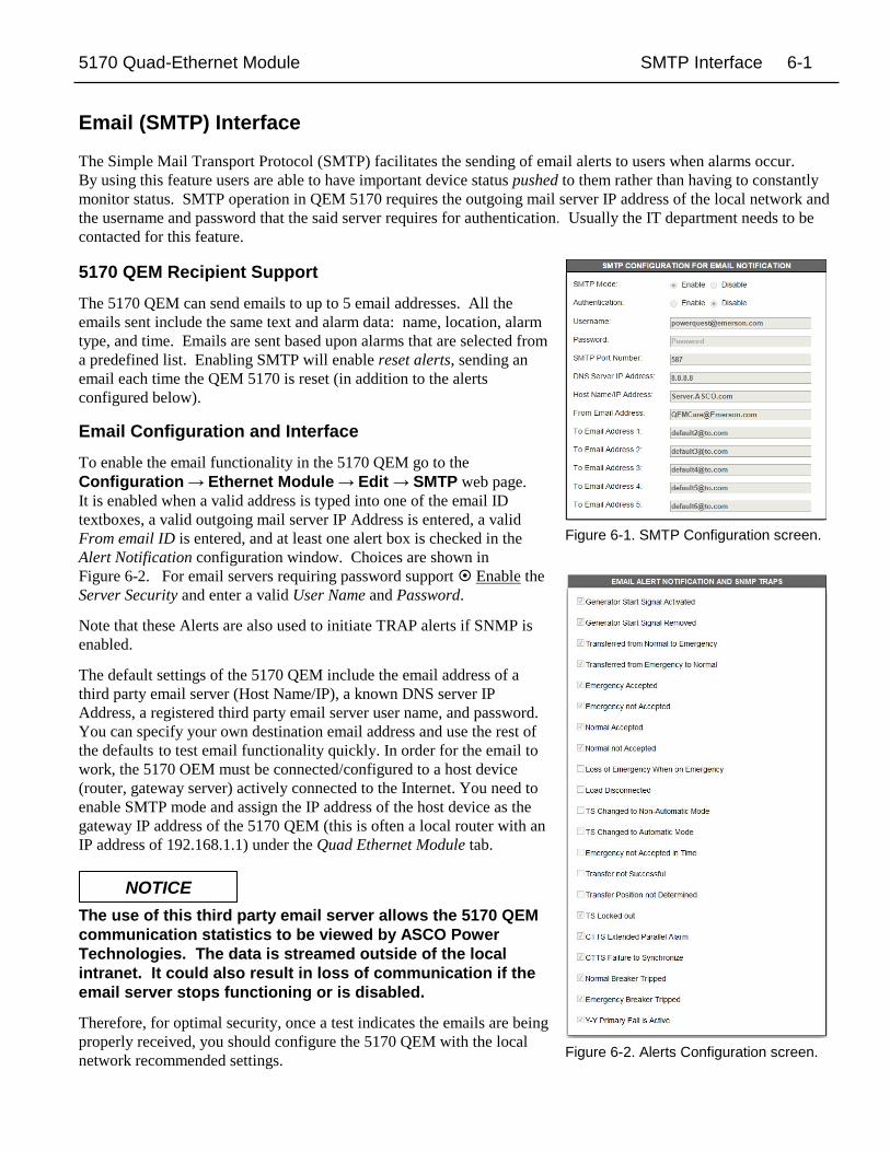
Figure 6-1. SMTP Configuration screen.
Email (SMTP) Interface
The Simple Mail Transport Protocol (SMTP) facilitates the sending of email alerts to users when alarms occur. By using this feature users are able to have important device status pushed to them rather than having to constantly monitor status. SMTP operation in QEM 5170 requires the outgoing mail server IP address of the local network and the username and password that the said server requires for authentication. Usually the IT department needs to be contacted for this feature. 5170 QEM Recipient Support The 5170 QEM can send emails to up to 5 email addresses. All the emails sent include the same text and alarm data: name, location, alarm type, and time. Emails are sent based upon alarms that are selected from a predefined list. Enabling SMTP will enable reset alerts, sending an email each time the QEM 5170 is reset (in addition to the alerts configured below).
Email Configuration and Interface To enable the email functionality in the 5170 QEM go to the Configuration → Ethernet Module → Edit → SMTP web page. It is enabled when a valid address is typed into one of the email ID textboxes, a valid outgoing mail server IP Address is entered, a valid From email ID is entered, and at least one alert box is checked in the Alert Notification configuration window. Choices are shown in Figure 6-2. For email servers requiring password support Enable the Server Security and enter a valid User Name and Password. Note that these Alerts are also used to initiate TRAP alerts if SNMP is enabled. The default settings of the 5170 QEM include the email address of a third party email server (Host Name/IP), a known DNS server IP Address, a registered third party email server user name, and password. You can specify your own destination email address and use the rest of the defaults to test email functionality quickly. In order for the email to work, the 5170 OEM must be connected/configured to a host device (router, gateway server) actively connected to the Internet. You need to enable SMTP mode and assign the IP address of the host device as the gateway IP address of the 5170 QEM (this is often a local router with an IP address of 192.168.1.1) under the Quad Ethernet Module tab. The use of this third party email server allows the 5170 QEM communication statistics to be viewed by ASCO Power Technologies. The data is streamed outside of the local intranet. It could also result in loss of communication if the email server stops functioning or is disabled. Therefore, for optimal security, once a test indicates the emails are being properly received, you should configure the 5170 QEM with the local network recommended settings. Figure 6-2. Alerts Configuration screen.
NOTICE

5170 Quad-Ethernet Module Configuration Details 7-1
5170 QEM Configuration Details
The 5170 QEM requires minimal configuration for most applications. Webpages allow the user to change how the 5170 QEM functions.
Configuration → Ethernet Module Configuration
The view webpage displays general IP address related settings, SNMP and email configuration, encryption support (if offered), and network settings. To change a setting, click the Edit button. Settings are divided into seven windows: ▪ The SNMP Configuration setup is discussed in the SNMP section. ▪ The SMTP Configuration for Email Notification settup is discussed in the email section. ▪ The Email Alert Notification & SNMP Traps window presents a list of alarms that can be activated. Enabling these alarms affects both the email data sent as part of SMTP functionality as well as the TRAP use in the SNMP configuration if either of these protocols is enabled. See the SNMP and/or email sections, if applicable. ▪ The Ethernet TCP/IPv4 window includes these sub areas:
The AES Mode encryption port and the ability to enable AES Encryption is used in conjunction with an ASCO Power Technologies monitoring solution, BMS, or SCADA system to add additional security. Both the 5170 QEM and the Ethernet master must use the same 128 bit encryption and communicate using the same port. Usually, particularly on LANs, this feature is not used. On some international non-encrypted versions these settings will not be available.
Enabling DHCP Mode (Dynamic Host Configuration Protocol) mode allows the IP address of the 5170 QEM to be set by a DHCP server – usually as part of an IT administered network. This is rarely used due to the need for a network to be well defined, usually done using static IP addresses. In case DHCP is enabled, contact the network administrator for the assigned IP address and duration policies.
The IP Address, Subnet Adress mask, and Gateway Address are network settings that will often be provided by the network manager. The default settings are 169.254.1.1, 255.255.0.0 and 0.0.0.0, respectively. Further information on changes to these settings should be addressed by the network manager.
The TCP port number might need to be changed if a BMS or SCADA system will be interfacing to the 5170 QEM. This setting will usually only be changed by an ASI technician. This port number applies to both Modbus/TCP and ASCOBusII/TCP.
NOTES: Leave settings as default when possible. Usually the changing of the IP Address is all that is required. After any changes are made to the configuration page, click the SAVE button. These changes will be saved and the webpage will revert back to the view page. If no changes are made the edit page will time out after three minutes. The Edit mode allows only one user login at a time. During the edit session access from all other users will be denied. Changing the Ethernet or SNMP Configuration will reset the 5170 QEM; a message appears that the 5170 QEM is reset. In a web browser, pop-up messages should be allowed. Otherwise, the 5170 QEM will not reset, and its webpage will display the older configuration. Click the OK button and close the pop-up window.
7-2 Configuration Details Quad Ethernet Module
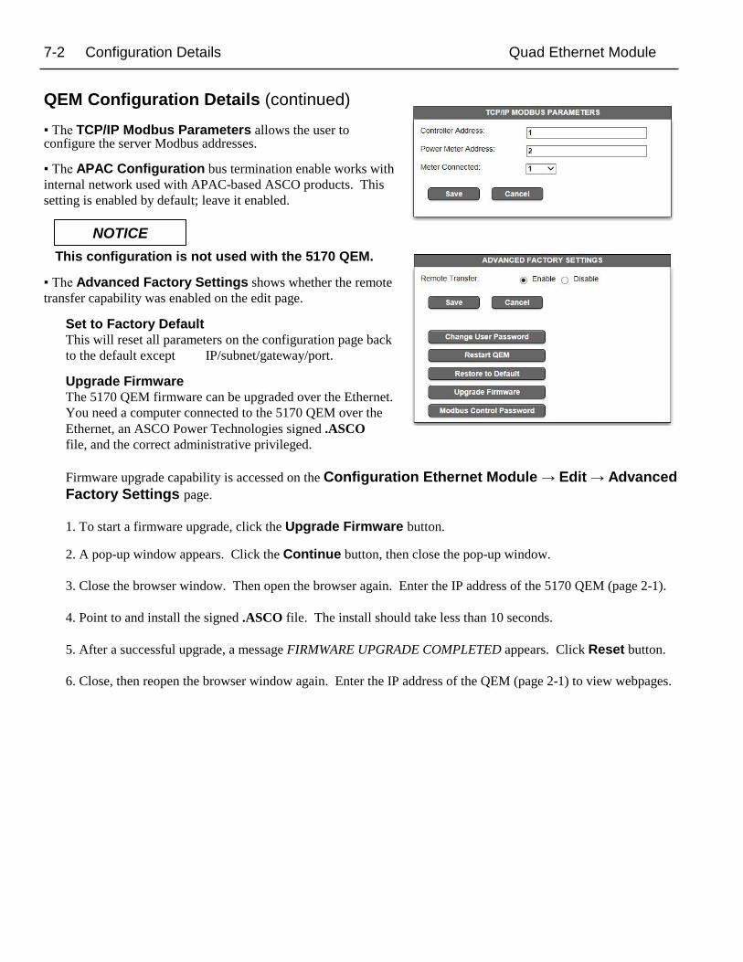
QEM Configuration Details (continued) ▪ The TCP/IP Modbus Parameters allows the user to configure the server Modbus addresses. ▪ The APAC Configuration bus termination enable works with internal network used with APAC-based ASCO products. This setting is enabled by default; leave it enabled. This configuration is not used with the 5170 QEM. ▪ The Advanced Factory Settings shows whether the remote transfer capability was enabled on the edit page.
Set to Factory Default This will reset all parameters on the configuration page back to the default except IP/subnet/gateway/port.
Upgrade Firmware The 5170 QEM firmware can be upgraded over the Ethernet. You need a computer connected to the 5170 QEM over the Ethernet, an ASCO Power Technologies signed .ASCO file, and the correct administrative privileged.
Firmware upgrade capability is accessed on the Configuration Ethernet Module → Edit → Advanced Factory Settings page.
1. To start a firmware upgrade, click the Upgrade Firmware button.
2. A pop-up window appears. Click the Continue button, then close the pop-up window.
3. Close the browser window. Then open the browser again. Enter the IP address of the 5170 QEM (page 2-1).
4. Point to and install the signed .ASCO file. The install should take less than 10 seconds.
5. After a successful upgrade, a message FIRMWARE UPGRADE COMPLETED appears. Click Reset button.
6. Close, then reopen the browser window again. Enter the IP address of the QEM (page 2-1) to view webpages.
NOTICE

5170 Quad-Ethernet Module Troubleshooting Appendix-1
Troubleshooting
To avoid possible shock, burns, or death, deenergize all electrical sources to the transfer switch before working on the 5170 QEM.
Status Lights (LEDs)
Power light This light should be on under normal operating conditions
LED Name Color Status Description
Power Green off
5170 QEM is not energized, it is turned off
on 5170 QEM is energized, it is turned on and working
Ethernet Connection Lights These lights should be blinking under normal operating conditions
LED Name Color Status Description
Activity Green off
There is no activity on the link
on Flashing indicates activity on the link
Link Speed Yellow off There is no link connection
on There is a link connection
TX Transmit off/on Off - no transmitting / On - transmitting
RX Receive off/on Off - no receiving / On - receiving
Diagnostic Light This light should be off under normal operating conditions
LED Name Color Status Description
Diagnostic Red
Solid on 5170 QEM in boot loader (starting up)
off 5170 QEM in normal operating condition
1 blink RAM checksum error
4 blinks Duplicate IP address on the network
Reset Button A reset button (hole in the top) is provided to reset the 5170 QEM to original default settings. These settings are: IP address, subnet mask, gateway address, TCP port number, and reply timeout. The reset button should only be used if you forget the IP address. (see page 2-1). It also resets all passwords to the default password.
Web Pages are not accessible If the 5170 QEM web page is not accessible, try the following procedure: 1. Open the command prompt on the computer. Type cmd 2. To monitor network connectivity status, type Ping xxx.xxx.xxx.xxx in command prompt. 3. The default prompt of the 5170 QEM is 169.254.1.1 (see page 2-1). 4. To monitor continuous network connectivity status, type Ping xxx.xxx.xxx.xxx -t in command prompt.
DANGER !
diagnostic light
power light
activity light
link speed light
receive light
transmit light
APAC
APAC
TTL
TTL
Ethernet Ethernet
Ethernet Ethernet

5170 Quad-Ethernet Module Types of Data/Control Appendix-2
Types of Data/Control found on Web pages
The following types of data and control are provided on 5170 QEM web pages, depending on the connected devices.
Dashboard web page ▪ Switch Status, Active Alerts, Timers ▪ Transfer Switch – Control Capability ▪ Voltage, Frequency, and Current Monitoring ▪ Transfer Switch / Generator Statistics If equipped with meter device ▪ Energy Consumption – Net KWH, KVAR, KVA ▪ Transfer Switch Rated Current Utilization ▪ Power Measurement – KW, KVA, KVAR, PF ▪ Voltage (L-L and L-N), Frequency, and Current Measurement
Transfer Switch Details web page (settings for view only) ▪ Pickup and Dropout Voltage Settings ▪ Frequency Trip Settings ▪ Engine Exerciser Settings ▪ Switch Status ▪ Active Alerts and Timers ▪ Transfer Switch and Engine Status
Power Meter Details web page (settings are view only) ▪ Energy Consumption ▪ Switch Status, Active Alerts, & Timers ▪ Historic KW Demand ▪ Maximum Load Demand Chart ▪ Power Measurement – KW, KVA, KVAR, PF ▪ Voltage, Current, Frequency, Power, and PF Measurement ▪ PT and CT ratios
Event Log page Events page shows the controller events logged into the 5170 QEM. Data included: event type, cause, timestamp.
Configuration web page ▪ There are two Ethernet Configuration pages. One is viewable only; the other allows setting changes (Admin level). ▪ Viewable and editable are IP, TCP, and Communication Settings as well as SNMP and email settings. ▪ User can also change device names & locations (these are only changes that can be made to downstream devices) from the configuration → device pages. ▪ The Configuration section is where a user can change the passwords (see page 2-1). ▪ Firmware upgrade access
About page ▪ The About page provides firmware versions of the 5170 QEM and devices that are connected downstream.
5170 Quad-Ethernet Module Glossary Appendix-3
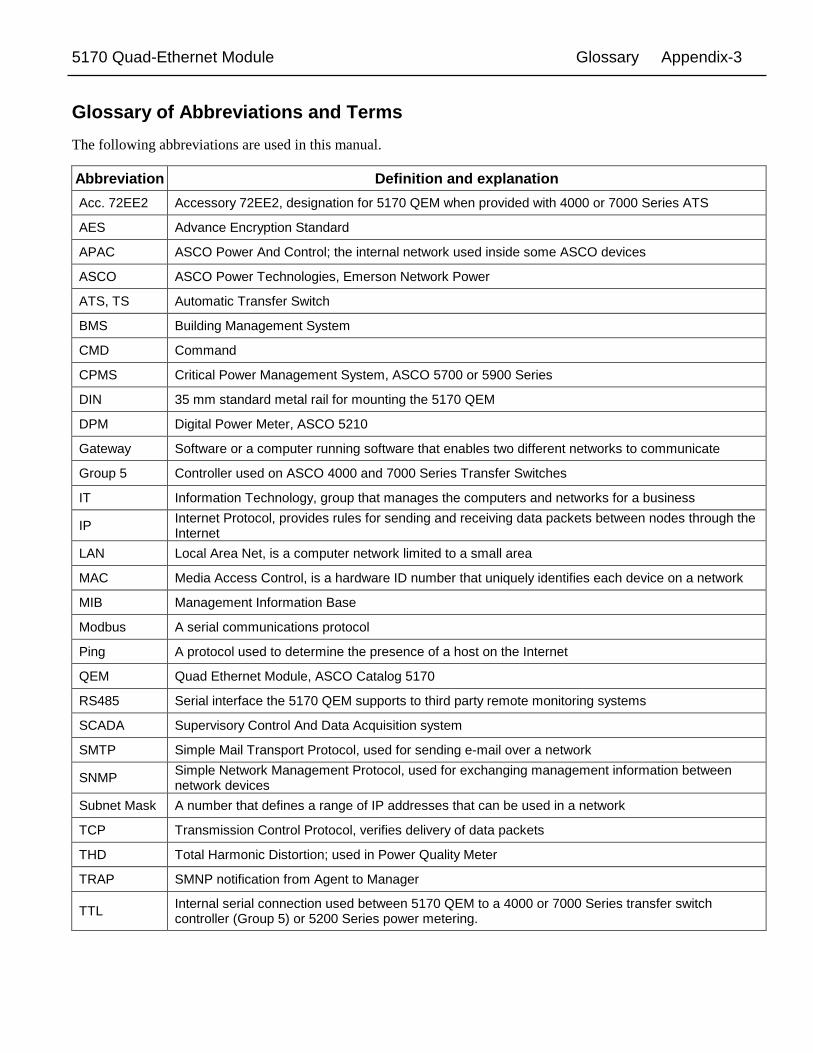
Glossary of Abbreviations and Terms
The following abbreviations are used in this manual.
Abbreviation Definition and explanation Acc. 72EE2 Accessory 72EE2, designation for 5170 QEM when provided with 4000 or 7000 Series ATS
AES Advance Encryption Standard
APAC ASCO Power And Control; the internal network used inside some ASCO devices
ASCO ASCO Power Technologies, Emerson Network Power
ATS, TS Automatic Transfer Switch
BMS Building Management System
CMD Command
CPMS Critical Power Management System, ASCO 5700 or 5900 Series
DIN 35 mm standard metal rail for mounting the 5170 QEM
DPM Digital Power Meter, ASCO 5210
Gateway Software or a computer running software that enables two different networks to communicate
Group 5 Controller used on ASCO 4000 and 7000 Series Transfer Switches
IT Information Technology, group that manages the computers and networks for a business
IP Internet Protocol, provides rules for sending and receiving data packets between nodes through the Internet
LAN Local Area Net, is a computer network limited to a small area
MAC Media Access Control, is a hardware ID number that uniquely identifies each device on a network
MIB Management Information Base
Modbus A serial communications protocol
Ping A protocol used to determine the presence of a host on the Internet
QEM Quad Ethernet Module, ASCO Catalog 5170
RS485 Serial interface the 5170 QEM supports to third party remote monitoring systems
SCADA Supervisory Control And Data Acquisition system
SMTP Simple Mail Transport Protocol, used for sending e-mail over a network
SNMP Simple Network Management Protocol, used for exchanging management information between network devices
Subnet Mask A number that defines a range of IP addresses that can be used in a network
TCP Transmission Control Protocol, verifies delivery of data packets
THD Total Harmonic Distortion; used in Power Quality Meter
TRAP SMNP notification from Agent to Manager
TTL Internal serial connection used between 5170 QEM to a 4000 or 7000 Series transfer switch controller (Group 5) or 5200 Series power metering.
Com
mun
icat
ion
Add
ress
For
m fo
r 517
0 Q
uad-
Ethe
rnet
Mod
ule
(QEM
)
Row
N
o.
IP A
ddre
ss
Sub
net
mas
k G
atew
ay
ATS
S
eria
l No.
A
TS
Cat
alog
No.
A
ddre
ss s
et in
A
TS C
ontro
ller*
A
ddre
ss s
et
in D
PM
1
2
3
4
5
6
7
8
9
10
11
12
13
14
15
16
In
stru
ctio
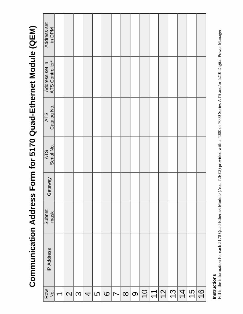
ns
Fill
in th
e in
form
atio
n fo
r eac
h 51
70 Q
uad-
Ethe
rnet
Mod
ule
(Acc
. 72E
E2) p
rovi
ded
with
a 4
000
or 7
000
Serie
s ATS
and
/or 5
210
Dig
ital P
ower
Man
ager
.

Printed in U.S.A. © ASCO Power Technologies, L.P. 2016 All Rights Reserved.
INDEX
A About, 3-2, Appendix 1 & 3 Acc. 72EE, 1-1, 3-2 Access Levels, 2-1 Admin, access level, 2-1 Address form, back of manual Addresses, 2-1 Alerts, 3-2, 5-1, 6-1, 7-1,
Appendix-3 APAC, 7-2, Appendix-3 ASCObusII TCP interface, 4-1
C Cable, communication, 1-1 Change Password, 2-1 Configuration, 3-2, 7-1, Appendix-3
Edit mode, 6-1, 7-1 Connections, 1-1 Control, access level, 2-1 Controller, Group 5, 3-2
User’s Guide, 381333-126 CT ratio, Appendix-3
D Dashboard, 3-2 Details, 3-2, Appendix 3 Devices, 3-2 Diagnostic light, Appendix-2 Dimensions, 1-1 DPM 5210, Appendix-3
Operator’s Manual 381333-368
E Edit mode, configuration,
5-1, 6-1, 7-1 Email alerts, 6-1 Engine Exerciser, Appendix-3
Group 5 Controller, 3-2 User’s Guide, 381333-126
Ethernet lights, Appendix-2 Events, 3-2 Event log screen, Appendix-3
F Firmware upgrade, Appendix-1 Form, communication address, back of manual
G Generator statistics, Appendix-3 Glossary, Appendix-4 Group 5 Controller, 3-2
User’s Guide, 381333-126
H Help, Troubleshooting, Appendix-2
1-800-800-2726 in the US [email protected]
I
Installation, 1-1 IP address, 2-1, 3-2
L LEDs, status, Appendix-2 Load transfer, 3-2 Login, 2-1, 3-1
M MAC address, 2-1 Manuals, 1-1
DPM 5210, 381333-368 PM Xp 5220, 381333-199
Modbus TCP interface, 4-1 Modbus Test Suite interface
example, see 381339-319 Monitor, access level, 2-1, 3-1 Mounting, 1-1
N Network, 1-1, 3-1
O Outline drawing, 1-1
P Password, 2-1, 3-1 Ports, 1-1 Power light, Appendix-2 Power Manager Xp,
Operator’s Manual 381333-199 Power Meter, Digital, Appendix-3
Operator’s Manual 381333-368 Power measurement, Appendix-3 Power requirements, 1-1 Protocol support, 5-1, 6-1 PT ratio, Appendix-3
R Outline drawing, 1-1
S SMTP interface, 6-1 SNMP interface, 5-1 SNMP Master configuration
iReasoning Master, see 381339-320
Specifications, 1-1 Status lights, Appendix-2 Switch Status, Appenix-3
T Timers, 3-2, Appendix-3
Group 5 Controller User’s Guide, 381333-126
Transfer Switch, 4000, 7000 Series Group 5 Controller, 3-2
User’s Guide, 381333-126 Web pages, Appendix-3
Troubleshooting, Appendix-2 TTL, Appendix-3 Types of Data/Control, Appendix-3
U User name (access level), 2-1, 3-1 User requirements, 3-1
V View mode, configuration, 7-1 Voltage, 1-1, 3-2
Group 5 Controller User’s Guide, 381333-199
W
Web page interface, 3-1 Web page design & navigation, 3-2