502-m822-2107b manual 01 - standardaudio.se · 502-m822-2107_manual_01.indd 1 2006/8/22 ¤w¤È...
TRANSCRIPT
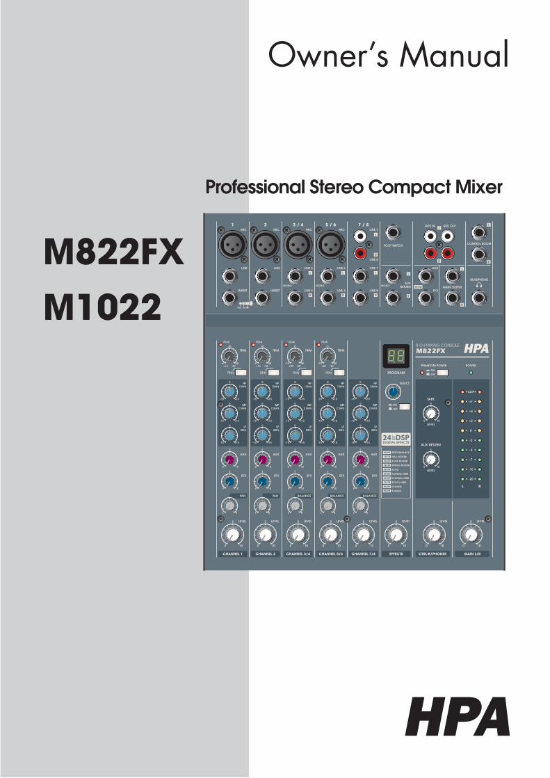
Owner’s Manual
M822FXM1022
Professional Stereo Compact Mixer
502-M822-2107_Manual_01.indd 1 2006/8/22 ¤W¤È 09:36:01
ON
OFF
ON
OFF
PHANTOM POWER
PROGRAM
POWER
TAPE
AUX RETURN
LEVEL
AUX
HF12kHz
MF2.5kHz
LF80Hz
PAN
0
5
10 0 10
LEVEL LEVEL LEVEL LEVEL
TRIM
PEAK
EFX
CHANNEL 1 CHANNEL 2
AUX
HF12kHz
MF2.5kHz
LF80Hz
0
5
10
TRIM
PEAK
EFX
CHANNEL 3/4 CHANNEL 5/6
BALANCE
0
5
10 0
5
10
LEVEL LEVEL
0
5
10
LEVEL
CHANNEL 7/8 EFFECTS CTRL-R/PHONES
0
5
10
MAIN L/R
RL
SELECT
-20
-10
-7
-4
-2
0
+2
+4
+7
CLIP
MAIN OUTPUT
AUX
FOOT SWITCH
LINE
INSERT
1MIC
LINE 7
LINE 8
7 / 8
LINE
INSERT
2MIC
LINE 3
LINE 4
3 / 4MIC
LINE 5
LINE 6
5 / 6MIC
TAPE IN REC OUTLINE 7
LINE 8
EFX
HEADPHONE
CONTROL ROOM
MONOMONO MONOAUX
RETURN
OUT IN
75Hz
-30+14-6 -50
30
-15 +15
0
-12 +12
0
-15 +15
0
0 10
5
0 10
5
L R
AUX
HF12kHz
MF2.5kHz
LF80Hz
PAN
5 LEVEL
TRIM
PEAK
EFX
-30+14-6 -50
30 0
-15 +15
0
-12 +12
0
-15 +15
0
-15 +15
0
-12 +12
0
-15 +15
0
0 10
5
0 10
5
L R
0 10
5
0 10
5
L R
LEVEL
AUX
HF12kHz
MF2.5kHz
LF80Hz
0
5
10
TRIM
PEAK
EFX
BALANCE
0
-15 +15
0
-12 +12
0
-15 +15
0
0 10
5
0 10
5
0 10
5
L R
AUX
HF12kHz
MF2.5kHz
LF80Hz
EFX
BALANCE
-15 +15
0
-12 +12
0
-15 +15
0
0 10
5
0 10
5
0 10
5
L R
8 CH MIXING CONSOLE
M822FX HPA
PERFORMANCE
HALL REVERB
PLATE REVERB
SPRING REVERB
ECHO
FLANGE+VERB
CHORUS+VERB
ECHO+VERB
CHORUS
FLANGE
75Hz 75Hz 75Hz
-20+20-10 -50
-20+20-10 -50
502-M822-2107_Manual_01.indd 2 2006/8/22 ¤W¤È 09:36:01
WARNING
1
M822FX / M1022
Introductions ...................................................................................... 2
Features .............................................................................................. 3
Front Panel Controls ........................................................................... 4
InputSection ............................................................................... 4
Master Section .......................................................................... 5
Input/Output Section Connectors .......................................... 6
Rear Panel Controls .......................................................................... 8
Point to Remember ........................................................................... 9
Connections ....................................................................................... 9
Applications......................................................................................11
BlockDiagram...................................................................................12
Specifications....................................................................................13
General Specifications 31..........................................................
Input/Output Specifications ..................................................14
Service...............................................................................................15
Procedures ..............................................................................15
Schematic ...............................................................................15
Parts List ..................................................................................15
Table of Contents
Table of Contents
502-M822-2107_Manual_01.indd 1 2006/8/22 ¤W¤È 09:36:02
2
M822FX / M1022
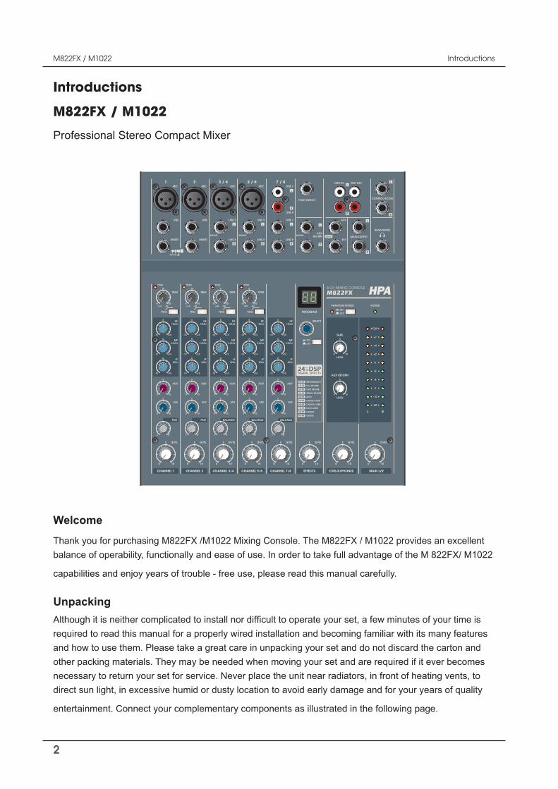
Introductions
Thank you for purchasing M822FX /M1022 Mixing Console. The M822FX / M1022 provides an excellent balance of operability, functionally and ease of use. In order to take full advantage of the M 822FX/ M1022
capabilities and enjoy years of trouble - free use, please read this manual carefully.
M822FX / M1022
Introductions
Professional Stereo Compact Mixer
Welcome
other packing materials.necessary to return your set for service. Never place the unit near radiators, in front of heating vents, to direct sun light, in excessive humid or dusty location to avoid early damage and for your years of quality
Unpacking
502-M822-2107_Manual_01.indd 2 2006/8/22 ¤W¤È 09:36:04
ON
OFF
ON
OFF
PHANTOM POWER
PROGRAM
POWER
TAPE
AUX RETURN
LEVEL
AUX
HF12kHz
MF2.5kHz
LF80Hz
PAN
0
5
10 0 10
LEVEL LEVEL LEVEL LEVEL
TRIM
PEAK
EFX
CHANNEL 1 CHANNEL 2
AUX
HF12kHz
MF2.5kHz
LF80Hz
0
5
10
TRIM
PEAK
EFX
CHANNEL 3/4 CHANNEL 5/6
BALANCE
0
5
10 0
5
10
LEVEL LEVEL
0
5
10
LEVEL
CHANNEL 7/8 EFFECTS CTRL-R/PHONES
0
5
10
MAIN L/R
RL
SELECT
-20
-10
-7
-4
-2
0
+2
+4
+7
CLIP
MAIN OUTPUT
AUX
FOOT SWITCH
LINE
INSERT
1MIC
LINE 7
LINE 8
7 / 8
LINE
INSERT
2MIC
LINE 3
LINE 4
3 / 4MIC
LINE 5
LINE 6
5 / 6MIC
TAPE IN REC OUTLINE 7
LINE 8
EFX
HEADPHONE
CONTROL ROOM
MONOMONO MONOAUX
RETURN
OUT IN
75Hz
-30+14-6 -50
30
-15 +15
0
-12 +12
0
-15 +15
0
0 10
5
0 10
5
L R
AUX
HF12kHz
MF2.5kHz
LF80Hz
PAN
5 LEVEL
TRIM
PEAK
EFX
-30+14-6 -50
30 0
-15 +15
0
-12 +12
0
-15 +15
0
-15 +15
0
-12 +12
0
-15 +15
0
0 10
5
0 10
5
L R
0 10
5
0 10
5
L R
LEVEL
AUX
HF12kHz
MF2.5kHz
LF80Hz
0
5
10
TRIM
PEAK
EFX
BALANCE
0
-15 +15
0
-12 +12
0
-15 +15
0
0 10
5
0 10
5
0 10
5
L R
AUX
HF12kHz
MF2.5kHz
LF80Hz
EFX
BALANCE
-15 +15
0
-12 +12
0
-15 +15
0
0 10
5
0 10
5
0 10
5
L R
8 CH MIXING CONSOLE
M822FX HPA
PERFORMANCE
HALL REVERB
PLATE REVERB
SPRING REVERB
ECHO
FLANGE+VERB
CHORUS+VERB
ECHO+VERB
CHORUS
FLANGE
75Hz 75Hz 75Hz
-20+20-10 -50
-20+20-10 -50
3
M822FX / M1022
Features
Features
-2 MONO ( M1022/M822FX) INPUT AND 3 STEREO ( M822FX ) ,4 STEREO ( M1022 )INPUT
Any sound source of microphones, cassette decks, electronic guitars, organs can be applied to the chan-nel input.
- MAIN L/R OUTPUT
Main L/R are provided for convenient use.
- AUX RETURN AND 2 AUX SEND
For convenient use of external equipment, AUX SEND and AUX RETURN function are provided.
- CHANNEL EQUALIZER
The 3 band equalizer are designed for ±15dB (HF,LF), ±12dB(MF) control on input channel.
- 2 MONO CHANNEL INSERT
- DSP FUNCTION : 100 SELECTABLE PRESETS (ONLY M822FX )
A built-in 24bit DSP(Digital Signal Processor ) with 100 selectable presets including Reverb, Delay and Chorus, offers dazzling studio quality effects.
- PHANTOM POWER(+48V)
- EXTERNAL AC POWER
Phantom power is provided for easy connection of condenser microphones requiring an external power supply.
502-M822-2107_Manual_01.indd 3 2006/8/22 ¤W¤È 09:36:04
4
M822FX / M1022
Front Panel Controls
Front Panel Controls
LEVEL
CHANNEL 2 CHANNEL 5/6
0
5
10
CHANNEL 7/8
AUX
HF12kHz
MF2.5kHz
LF80Hz
PAN
5 LEVEL
TRIM
PEAK
EFX
-30+14-6 -50
30
-15 +15
0
-12 +12
0
-15 +15
0
0 10
5
0 10
5
L R
LEVEL
AUX
HF12kHz
MF2.5kHz
LF80Hz
0
5
10
TRIM
PEAK
EFX
BALANCE
0
-15 +15
0
-12 +12
0
-15 +15
0
0 10
5
0 10
5
0 10
5
L R
AUX
HF12kHz
MF2.5kHz
LF80Hz
EFX
BALANCE
-15 +15
0
-12 +12
0
-15 +15
0
0 10
5
L R
75Hz 75Hz
-20+20-10 -50
1
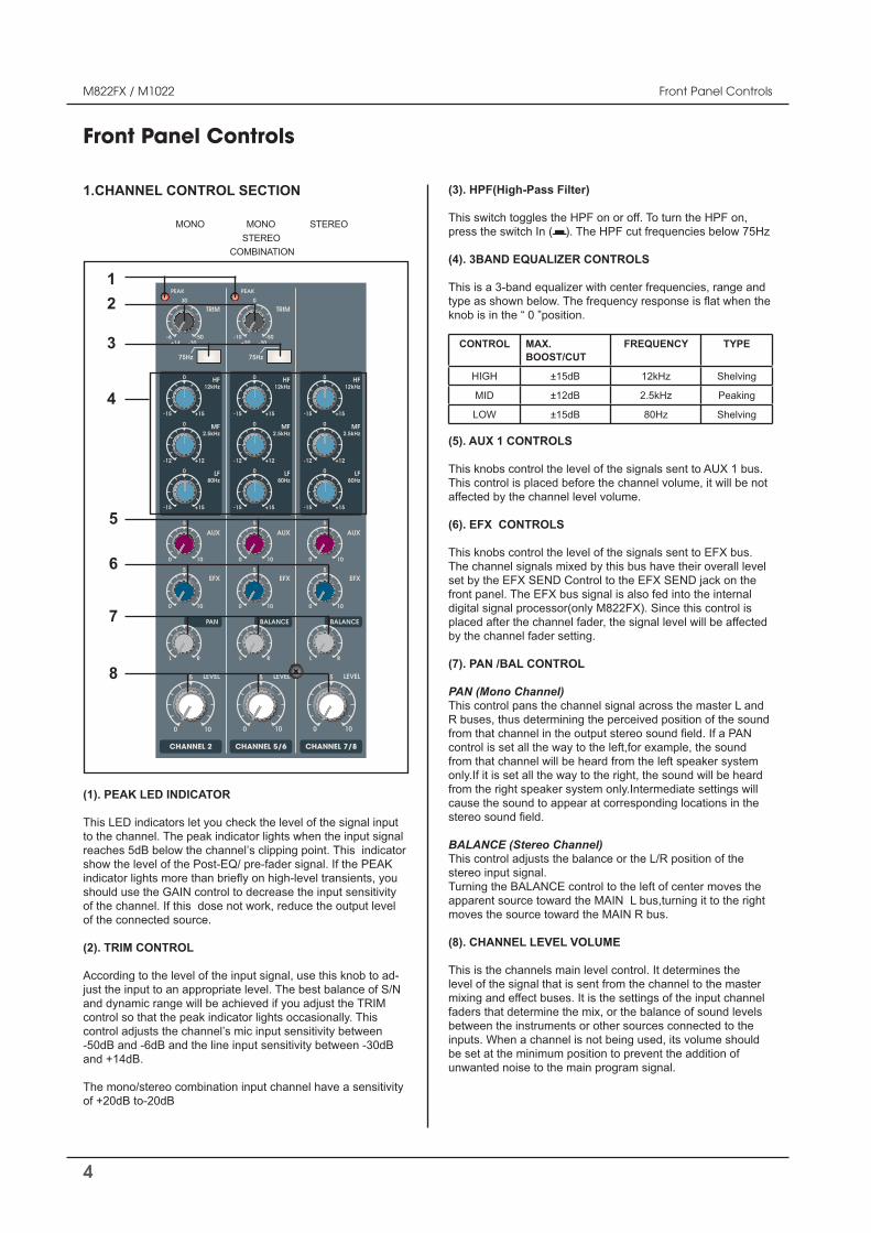
1.CHANNEL CONTROL SECTION
(1). PEAK LED INDICATOR
This LED indicators let you check the level of the signal input to the channel. The peak indicator lights when the input signal reaches 5dB below the channel’s clipping point. This indicator show the level of the Post-EQ/ pre-fader signal. If the PEAK
should use the GAIN control to decrease the input sensitivity
of the connected source.
(2). TRIM CONTROL
-just the input to an appropriate level. The best balance of S/N and dynamic range will be achieved if you adjust the TRIMcontrol so that the peak indicator lights occasionally. Thiscontrol adjusts the channel’s mic input sensitivity between -50dB and -6dB and the line input sensitivity between -30dB and +14dB.
The mono/stereo combination input channel have a sensitivity of +20dB to-20dB
(3). HPF(High-Pass Filter)
This switch toggles the HPF on or off. Tpress the switch In ( ). The HPF cut frequencies below 75Hz
(4). 3BAND EQUALIZER CONTROLS
type as shown below.knob is in the “ 0 ”position.
CONTROL MAX.BOOST/CUT
FREQUENCY TYPE
HIGH ±15dB 12kHz Shelving
MID ±12dB 2.5kHz Peaking
LOW ±15dB 80Hz Shelving
(5). AUX 1 CONTROLS
This knobs control the level of the signals sent to AUX 1 bus.
affected by the channel level volume.
(6). EFX CONTROLS
This knobs control the level of the signals sent to EFX bus. The channel signals mixed by this bus have their overall level set by the EFX SEND Control to the EFX SEND jack on the front panel. The EFX bus signal is also fed into the internal digital signal processor(only M822FX). Since this control is placed after the channel fader ffectedby the channel fader setting.
(7). PAN /BAL CONTROL
PAN (Mono Channel)This control pans the channel signal across the master L and
PAN
from that channel will be heard from the left speaker system onlyfrom the right speaker system only.Intermediate settings will cause the sound to appear at corresponding locations in the
BALANCE (Stereo Channel)This control adjusts the balance or the L/R position of the stereo input signal.Turning the BALANCE control to the left of center moves the apparent source toward the MAIN Lmoves the source toward the MAIN R bus.
(8). CHANNEL LEVEL VOLUME
This is the channels main level control. It determines the level of the signal that is sent from the channel to the master mixing and effect buses. It is the settings of the input channel
between the instruments or other sources connected to the
be set at the minimum position to prevent the addition of unwanted noise to the main program signal.
2
3
4
5
6
7
8
502-M822-2107_Manual_01.indd 4 2006/8/22 ¤W¤È 09:36:05
0 10
MONO MONO STEREO STEREO COMBINATION
5
M822FX / M1022
Front Panel Controls
Front Panel Controls
ON
OFF
ON
OFF
PHANTOM POWER
PROGRAM
POWER
TAPE
AUX RETURN
LEVEL
LEVEL
0
5
10
LEVEL LEVEL
0
5
10
LEVEL
EFFECTS CTRL-R/PHONES
0
5
10
MAIN L/R
RL
SELECT
-20
-10
-7
-4
-2
0
+2
+4
+7
CLIP
0 10
5
0 10
5
8 CH MIXING CONSOLE
M822FX HPA
PERFORMANCE
HALL REVERB
PLATE REVERB
SPRING REVERB
ECHO
FLANGE+VERB
CHORUS+VERB
ECHO+VERB
CHORUS
FLANGE
1
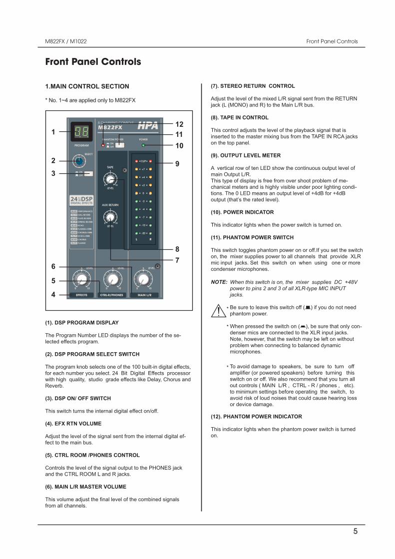
1.MAIN CONTROL SECTION
(1). DSP PROGRAM DISPLAY
The Program Number LED displays the number of the se-lected effects program.
(2). DSP PROGRAM SELECT SWITCH
The program knob selects one of the 100 built-in digital effects,for each number you select. 24 Bit Digital Effects processor with high quality, studio grade effects like Delay, Chorus and Reverb.
(3). DSP ON/ OFF SWITCH
This switch turns the internal digital effect on/off.
(4). EFX RTN VOLUME
Adjust the level of the signal sent from the internal digital ef-fect to the main bus.
(5). CTRL ROOM /PHONES CONTROL
Controls the level of the signal output to the PHONES jack and the CTRL ROOM L and R jacks.
(6). MAIN L/R MASTER VOLUME
from all channels.
* No. 1~4 are applied only to M822FX
(7). STEREO RETURN CONTROL
Adjust the level of the mixed L/R signal sent from the RETURN jack (L (MONO) and R) to the Main L/R bus.
(8). TAPE IN CONTROL
This control adjusts the level of the playback signal that is inserted to the master mixing bus from the TAPE IN RCA jacks on the top panel.
(9). OUTPUT LEVEL METER
A vertical row of ten LED show the continuous output level of main Output L/R.This type of display is free from over shoot problem of me-chanical meters and is highly visible under poor lighting condi-tions. The 0 LED means an output level of +4dB for +4dB output (that’s the rated level).
(10). POWER INDICATOR
This indicator lights when the power switch is turned on.
(11). PHANTOM POWER SWITCH
This switch toggles phantom power on or off.If you set the switch on, the mixer supplies power to all channels that provide XLR mic input jacks. Set this switch on when using one or more condenser microphones.
2
3
4
5
678
9
101112
When this switch is on, the mixer supplies DC +48V power to pins 2 and 3 of all XLR-type MIC INPUT jacks.
Be sure to leave this switch off ( ) if you do not need phantom power.
When pressed the switch on ( ), be sure that only con-denser mics are connected to the XLR input jacks.Note, however, that the switch may be left on without problem when connecting to balanced dynamic microphones.
To avoid damage to speakers, be sure to turn off
switch on or off. We also recommend that you turn all out controls ( MAIN L/R , CTRL - R / phones , etc). to minimum settings before operating the switch, to avoid risk of loud noises that could cause hearing loss or device damage.
(12). PHANTOM POWER INDICATOR
This indicator lights when the phantom power switch is turned on.
NOTE:
502-M822-2107_Manual_01.indd 5 2006/8/22 ¤W¤È 09:36:06
*
*
*
6
M822FX / M1022
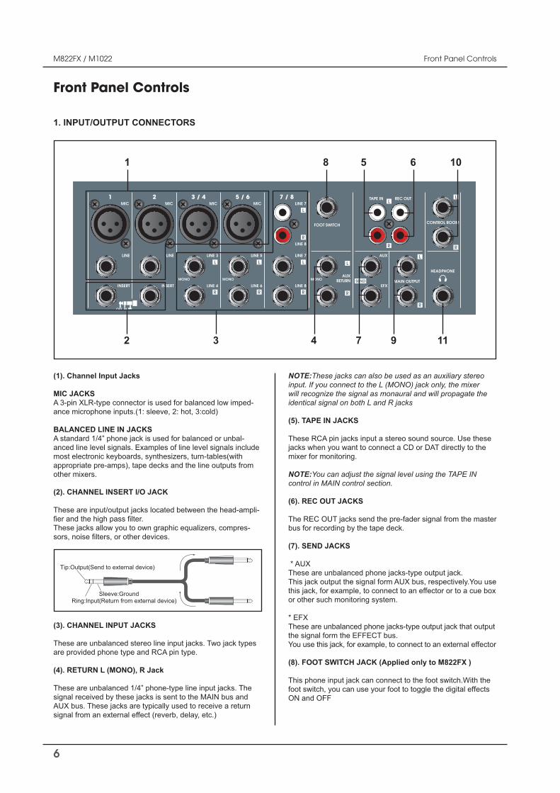
(1). Channel Input Jacks
MIC JACKS A 3-pin XLR-type connector is used for balanced low imped-ance microphone inputs.(1: sleeve, 2: hot, 3:cold)
BALANCED LINE IN JACKS A standard 1/4” phone jack is used for balanced or unbal-anced line level signals. Examples of line level signals include most electronic keyboards, synthesizers, turn-tables(with appropriate pre-amps), tape decks and the line outputs from other mixers.
(2). CHANNEL INSERT I/O JACK
These are input/output jacks located between the head-ampli-r.
These jacks allow you to own graphic equalizers, compres-
1. INPUT/OUTPUT CONNECTORS
Front Panel Controls
Front Panel Controls
MAIN OUTPUT
AUX
FOOT SWITCH
LINE
INSERT
1MIC
LINE 7
LINE 8
7 / 8
LINE
INSERT
2MIC
LINE 3
LINE 4
3 / 4MIC
LINE 5
LINE 6
5 / 6MIC
TAPE IN REC OUTLINE 7
LINE 8
EFX
HEADPHONE
CONTROL ROOM
MONOMONO MONOAUX
RETURN
OUT IN
1
2 3 4 7 9 11
5 6 108
Tip:Output(Send to external device)
Sleeve:GroundRing:Input(Return from external device)
(3). CHANNEL INPUT JACKS
These are unbalanced stereo line input jacks. Two jack types are provided phone type and RCA pin type.
(4). RETURN L (MONO), R Jack
These are unbalanced 1/4” phone-type line input jacks. Thesignal received by these jacks is sent to the MAIN bus and AUX bus. These jacks are typically used to receive a return signal from an external effect (reverb, delay, etc.)
NOTE:These jacks can also be used as an auxiliary stereo input. If you connect to the L (MONO) jack only, the mixer will recognize the signal as monaural and will propagate the identical signal on both L and R jacks
(5). TAPE IN JACKS
These RCA pin jacks input a stereo sound source. Use these jacks when you want to connect a CD or DAT directly to the mixer for monitoring.
NOTE:You can adjust the signal level using the TAPE IN control in MAIN control section.
(6). REC OUT JACKS
The REC OUT jacks send the pre-fader signal from the masterbus for recording by the tape deck.
(7). SEND JACKS
* AUXThese are unbalanced phone jacks-type output jack. This jack output the signal form AUX bus, respectively.You use this jack, for example, to connect to an effector or to a cue box or other such monitoring system.
* EFXThese are unbalanced phone jacks-type output jack that output the signal form the EFFECT bus.You use this jack, for example, to connect to an external effector
(8). FOOT SWITCH JACK (Applied only to M822FX )
This phone input jack can connect to the foot switch.With the foot switch, you can use your foot to toggle the digital effectsON and OFF
502-M822-2107_Manual_01.indd 6 2006/8/22 ¤W¤È 09:36:07
7
M822FX / M1022
Front Panel Controls
Front Panel Controls
(9). MAIN L/R OUTPUT JACKS
These jacks deliver stereo output of the mixer signal. You use
driving your main speakers. You also use these jacks when you wish to record the signal utilizing the level control applied by the main volume in the main Control section.
(10). CONTROL ROOM OUTPUT JACKS
Use these stereo phone-type output jacks to connect to your monitor system.
NOTE:The main output siguals also route to these fackscontvoleel by the CTRL-R / phones volume.
NOTE:The main output siguals also route to these fackscontvoleel by the CTRL-R / phones volume.
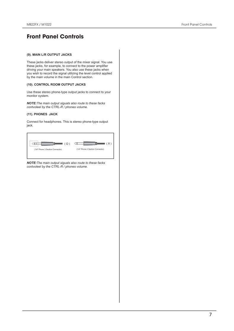
(11). PHONES JACK
Connect for headphones. This is stereo phone-type output jack.
(1/4" Phone 3 Section Connector)
( O )
(1/4" Phone 2 Section Connector)
( X )
502-M822-2107_Manual_01.indd 7 2006/8/22 ¤W¤È 09:36:07
8
M822FX / M1022
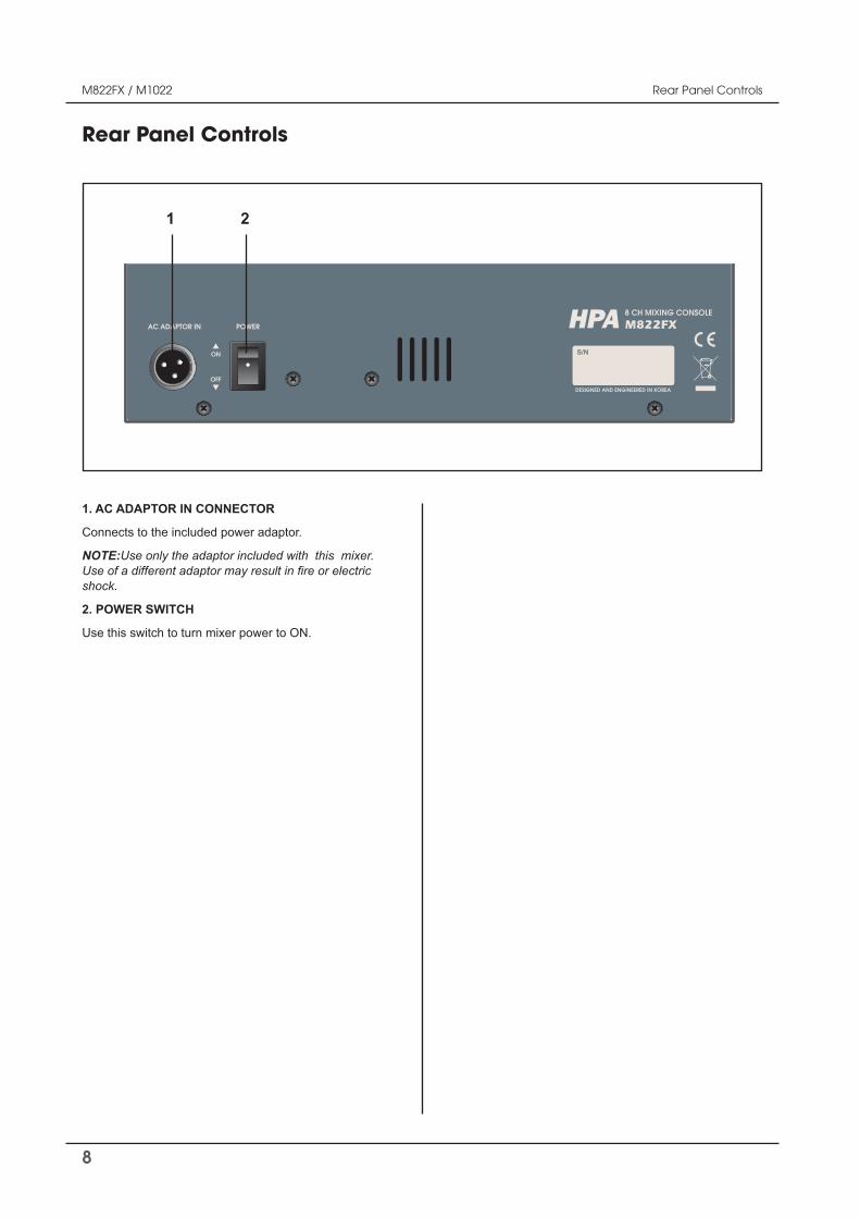
1. AC ADAPTOR IN CONNECTOR
Connects to the included power adaptor.
NOTE:Use only the adaptor included with this mixer.
shock.
2. POWER SWITCH
Use this switch to turn mixer power to ON.
Rear Panel Controls
Rear Panel Controls
DESIGNED AND ENGINEERED IN KOREA
POWERAC ADAPTOR IN
ON
OFF
8 CH MIXING CONSOLE
M822FXHPA
21
502-M822-2107_Manual_01.indd 8 2006/8/22 ¤W¤È 09:36:07
9
M822FX / M1022
Points to Remember
Points to Remember
- Do not disconnect the mains earth from each piece of equipment. This is needed to provided both safety and screen returns to the system star point.
and/or other equipment, to avoid earth loops.
-
for many forms of RF interference generated by electric motors, air-conditioning units, thyristor light dimmers etc.
no alternative but to provide a completely separate and independent ‘technical earth’ to replace the incoming ‘noisy
supply authority to ensure that safety regulations are not being infringed.
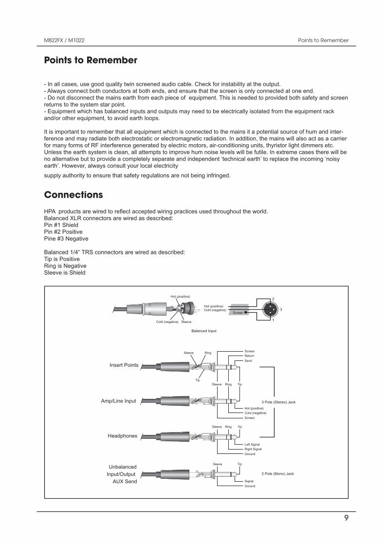
Insert Points
Amp/Line Input
Headphones
UnbalancedInput/Output
AUX Send
Ring
Ring
TipTip
Sleeve
Sleeve
SendReturnScreen
Hot (positive)Cold (negative)
Screen
Left SignalRight SignalGround
SignalGround
3 Pole (Stereo) Jack
2 Pole (Mono) Jack
Ring TipSleeve
TipSeeve
2
1
3
Balanced Input
Hot (positive)
Hot (positive)
Sleeve
Screen
Cold (negative)
Cold (negative)
Pin #1 ShieldPin #2 PositivePine #3 Negative
Tip is PositiveRing is NegativeSleeve is Shield
Connections
502-M822-2107_Manual_01.indd 9 2006/8/22 ¤W¤È 09:36:07
10
M822FX / M1022 Connections
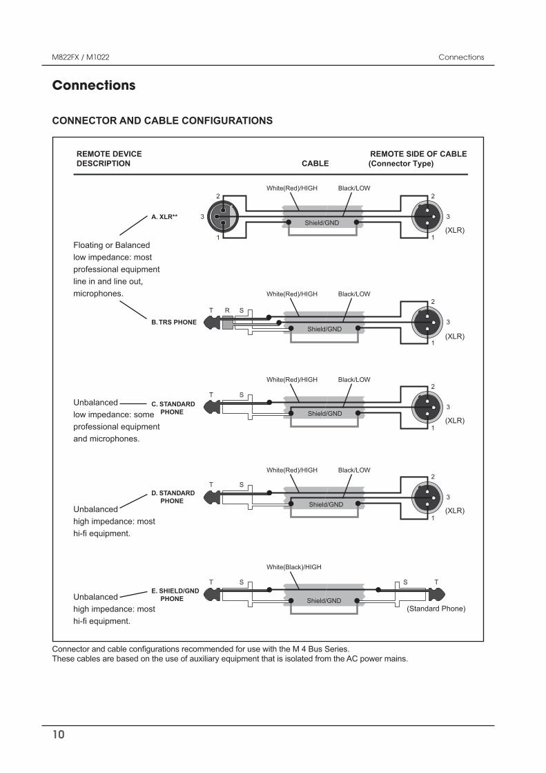
CONNECTOR AND CABLE CONFIGURATIONS
2
3
1
T R S
2
3
1
2
3
1
(XLR)
(XLR)
White(Red)/HIGH
A. XLR**
B. TRS PHONE
Black/LOW
Shield/GND
White(Red)/HIGH Black/LOW
Shield/GND
T S
T TSS
2
3
1(XLR)
(Standard Phone)
D. STANDARD PHONE
E. SHIELD/GND PHONE
White(Red)/HIGH Black/LOW
Shield/GND
White(Black)/HIGH
Shield/GND
T S2
3
1(XLR)
C. STANDARD PHONE
White(Red)/HIGH Black/LOW
Shield/GND
Floating or Balancedlow impedance: most professional equipmentline in and line out,microphones.
Unbalancedlow impedance: someprofessional equipmentand microphones.
Unbalancedhigh impedance: most hi-fi equipment.
Unbalancedhigh impedance: most hi-fi equipment.
REMOTE DEVICE REMOTE SIDE OF CABLEDESCRIPTION CABLE (Connector Type)
Connections
502-M822-2107_Manual_01.indd 10 2006/8/22 ¤W¤È 09:36:08
11
M822FX / M1022 Applications
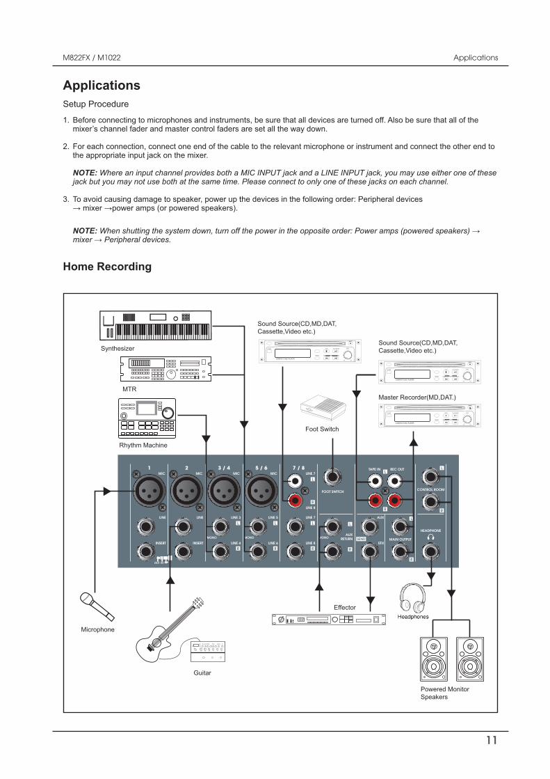
ApplicationsSetup Procedure
MAIN OUTPUT
AUX
FOOT SWITCH
LINE
INSERT
1MIC
LINE 7
LINE 8
7 / 8
LINE
INSERT
2MIC
LINE 3
LINE 4
3 / 4MIC
LINE 5
LINE 6
5 / 6MIC
TAPE IN REC OUTLINE 7
LINE 8
EFX
HEADPHONE
CONTROL ROOM
MONOMONO MONOAUX
RETURN
OUT IN
Microphone
Guitar
Effector
Powered MonitorSpeakers
Foot Switch
Sound Source(CD,MD,DAT,Cassette,Video etc.)
Sound Source(CD,MD,DAT,Cassette,Video etc.)
Master Recorder(MD,DAT.)
Synthesizer
MTR
Rhythm Machine
COMPACT DISC PLAYER
PROGRAM EJECT
POWER
REPEAT SKIP FWD
MIN MAX
PLAY/PAUSE LEVELSTOP
REW
COMPACT DISC PLAYER
PROGRAM EJECT
POWER
REPEAT SKIP FWD
MIN MAX
PLAY/PAUSE LEVELSTOP
REW
COMPACT DISC PLAYER
PROGRAM EJECT
POWER
REPEAT SKIP FWD
MIN MAX
PLAY/PAUSE LEVELSTOP
REW
Before connecting to microphones and instruments, be sure that all devices are turned off. Also be sure that all of the
For each connection, connect one end of the cable to the relevant microphone or instrument and connect the other end to the appropriate input jack on the mixer.
NOTE: Where an input channel provides both a MIC INPUT jack and a LINE INPUT jack, you may use either one of these jack but you may not use both at the same time. Please connect to only one of these jacks on each channel.
NOTE:
1.
2.
3.
Home Recording
502-M822-2107_Manual_01.indd 11 2006/8/22 ¤W¤È 09:36:09
12
M822FX / M1022
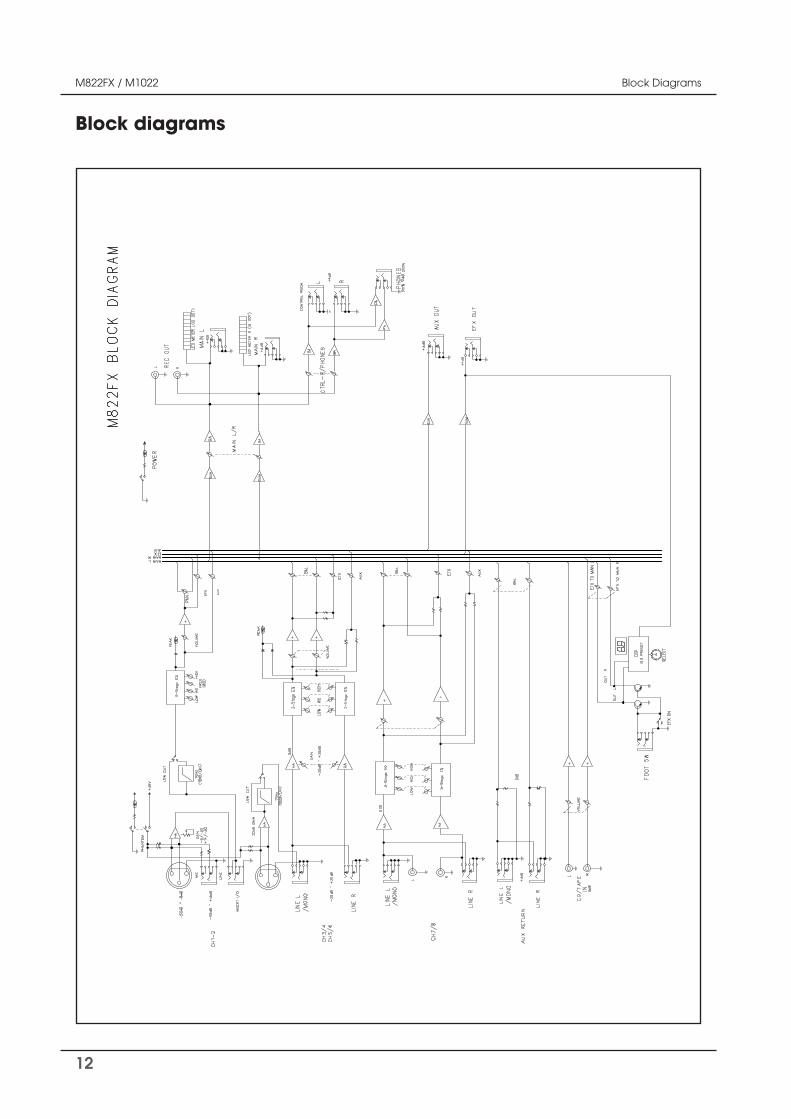
Block diagrams
Block Diagrams
502-M822-2107_Manual_01.indd 12 2006/8/22 ¤W¤È 09:36:09
13
M822FX / M1022 Specifications
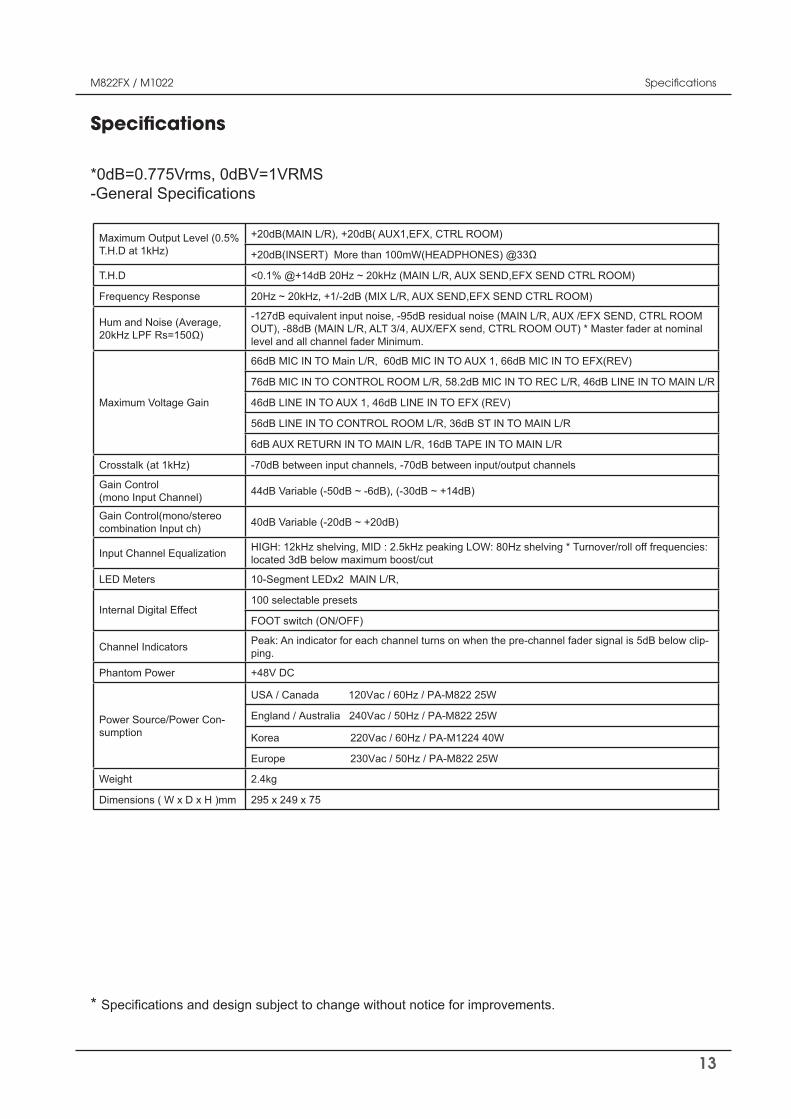
Specifications
*0dB=0.775Vrms, 0dBV=1VRMS
*
502-M822-2107_Manual_01.indd 13 2006/8/22 ¤W¤È 09:36:09
T R
T.H.D
T
V
T T T
T T T
T T
T T T
6dB T T T
V
V
T
T
n -
-
14
M822FX / M1022 Specifications
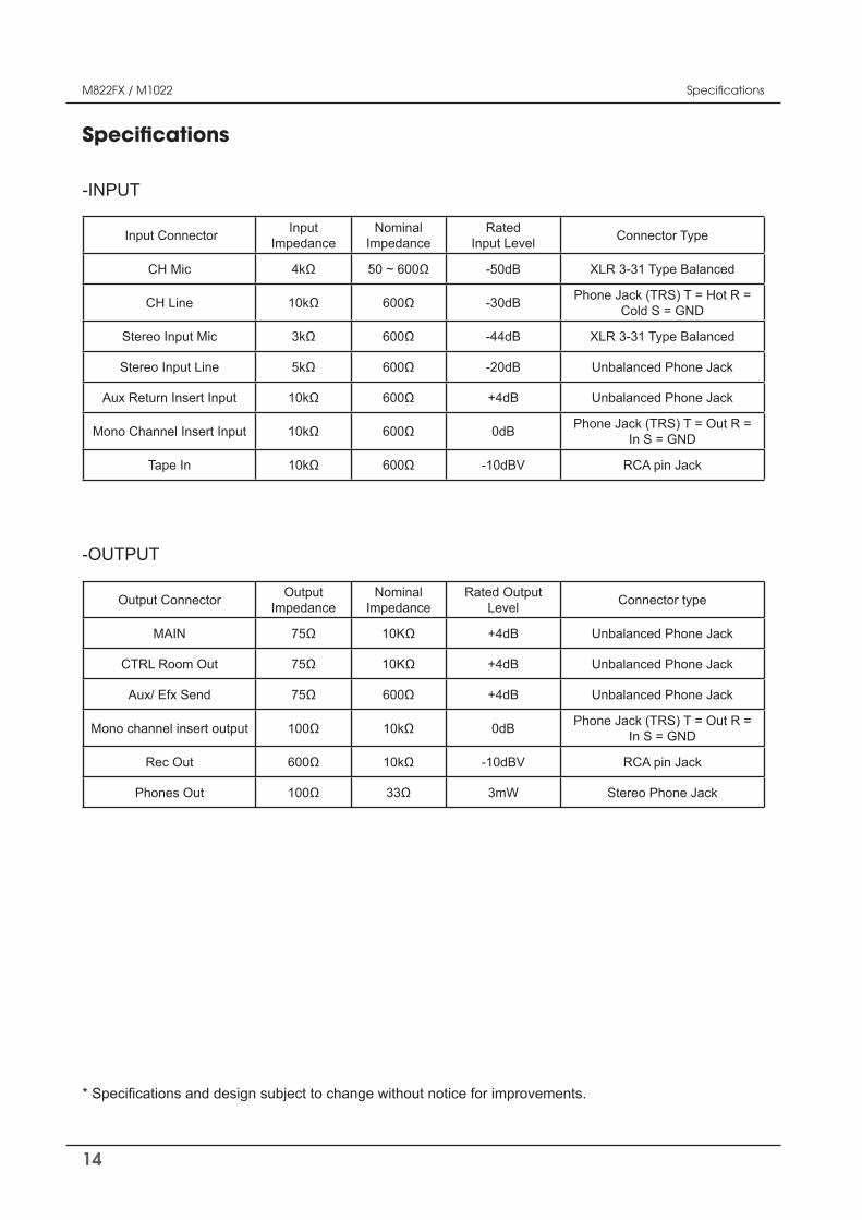
Specifications
Input Connector InputImpedance
NominalImpedance
RatedInput Level Connector Type
-50dB XLR 3-31 Type Balanced
-30dB Cold S = GND
Stereo Input Mic -44dB XLR 3-31 Type Balanced
Stereo Input Line -20dB Unbalanced Phone Jack
Aux Return Insert Input +4dB Unbalanced Phone Jack
Mono Channel Insert Input 0dB Phone Jack (TRS) T = Out R = In S = GND
Tape In RCA pin Jack
-INPUT
Output Connector OutputImpedance
NominalImpedance
Rated Output Level Connector type
MAIN +4dB Unbalanced Phone Jack
CTRL Room Out +4dB Unbalanced Phone Jack
Aux/ Efx Send +4dB Unbalanced Phone Jack
Mono channel insert output 0dB Phone Jack (TRS) T = Out R = In S = GND
Rec Out RCA pin Jack
Phones Out 3mW Stereo Phone Jack
-OUTPUT
502-M822-2107_Manual_01.indd 14 2006/8/22 ¤W¤È 09:36:09
15
M822FX / M1022
Service
Procedures
-
-tion of this manual.
Schematic
Parts List
Variations
Options
No optional items are available for this product.
Warranty terms and conditions vary by country and may not be the same for all products. Terms and con-
-
Variations and Options
Warranty
Service
502-M822-2107_Manual_01.indd 15 2006/8/22 ¤W¤È 09:36:09

16
M822FX / M1022
502-M822-2107_Manual_01.indd 16 2006/8/22 ¤W¤È 09:36:09

17
M822FX / M1022
502-M822-2107_Manual_01.indd 17 2006/8/22 ¤W¤È 09:36:10

502-M822-2107_Manual_01.indd 18 2006/8/22 ¤W¤È 09:36:10