502-14 relays and microscopes - wp.optics.arizona.edu · 14-5 prism specification – reduced...
TRANSCRIPT

OP
TI-502 O
ptical Design and Instrum
entation I©
Copyright 2019 John E
. Greivenkam
p
14-1
Section 14
Relays and Microscopes
OP
TI-502 O
ptical Design and Instrum
entation I©
Copyright 2019 John E
. Greivenkam
p
14-2Image Erection
The image produced by a Keplerian telescope is inverted and reverted. For many applications, such as terrestrial telescopes and binoculars, it is important that the image has the same orientation as the object. An image erection method must be added to the telescope system.
Methods: Prisms Porro SystemPorro-Abbe SystemPechan-RoofAbbe-Köenig
Relay systems

OP
TI-502 O
ptical Design and Instrum
entation I©
Copyright 2019 John E
. Greivenkam
p
14-3Prism Specification
The erecting prism in a Keplerian telescope or binoculars is usually placed between the objective lens and the intermediate image. It must be sized so that the entrance and exit faces do not vignette the FOV. To minimize weight, the prism is usually as small as possible.
The prism tunnel diagram allows the prism to be modeled as a plane parallel plate of glass. The prism geometry relates the sizes of the prism faces to the length of the tunnel diagram.
Consider the common Porro System:
Prism 1 Prism 2
L = 4a
a
a
a
OP
TI-502 O
ptical Design and Instrum
entation I©
Copyright 2019 John E
. Greivenkam
p
14-4Prism Specification
The telescope layout is now modified to include the tunnel diagram of the erecting prism system. The tunnel diagram (and therefore the prism) must be sized as to not vignette any rays for the specified FOV or intermediate image size. The prism dimensions are determined.
z
EYEfOBJfFIELDf
XP
Telescope layout:
z
EYEfOBJfFIELDf
XP
OBJf
Refraction at the surfaces of the plane parallel plate model of the prism must be included as well as the accompanying shift of the intermediate image plane.

OP
TI-502 O
ptical Design and Instrum
entation I©
Copyright 2019 John E
. Greivenkam
p
14-5Prism Specification – Reduced Tunnel Diagram
The reduced tunnel diagram can be used to simply determine the prism sizes without refracting the rays or shifting the intermediate image plane. An air-equivalent prism is used. The reduced tunnel diagram is sized so that all of the rays are unvignetted.
L = 4a
a a
L/n = 4a/n
z
EYEfOBJfFIELDf
XP
The physical size of the prism can then be determined from the size of the reduced tunnel diagram on the schematic.
OP
TI-502 O
ptical Design and Instrum
entation I©
Copyright 2019 John E
. Greivenkam
p
14-6TIR Limit in Prism Systems
The fastest f/# or NA that a prism will support is limited by the loss of Total Internal Reflection at the hypotenuse of the prism.
Consider a right angle prism in air:The top ray will lose TIR before the bottom ray and therefore defines the NA limit.
1C
U
U C
1C
1sin
45
At the TIR limit:
145 45 sin
n
nsin sinn
1 1Limiting NA sin sin 45 sinn
n
n '
' U º
L º
sin sin NA nsin in airNA
OP
TI-502 O
ptical Design and Instrum
entation I©
Copyright 2019 John E
. Greivenkam
p
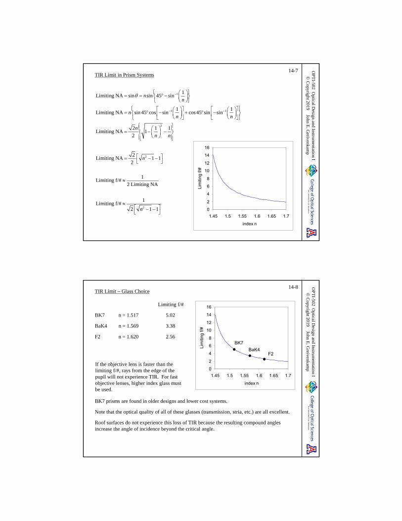
14-7TIR Limit in Prism Systems
1
1 1
2
2
1Limiting NA sin sin 45 sin
1 1Limiting NA sin 45 cos sin cos45 sin sin
2 1 1Limiting NA 1
2
2Limiting NA 1 1
2
1Limiting f/#
2
nn
nn n
n
n n
n
2
Limiting NA
1Limiting f/#
2 1 1n
0
2
4
6
8
10
12
14
16
1.45 1.5 1.55 1.6 1.65 1.7
index n
Lim
itin
g f/#
OP
TI-502 O
ptical Design and Instrum
entation I©
Copyright 2019 John E
. Greivenkam
p
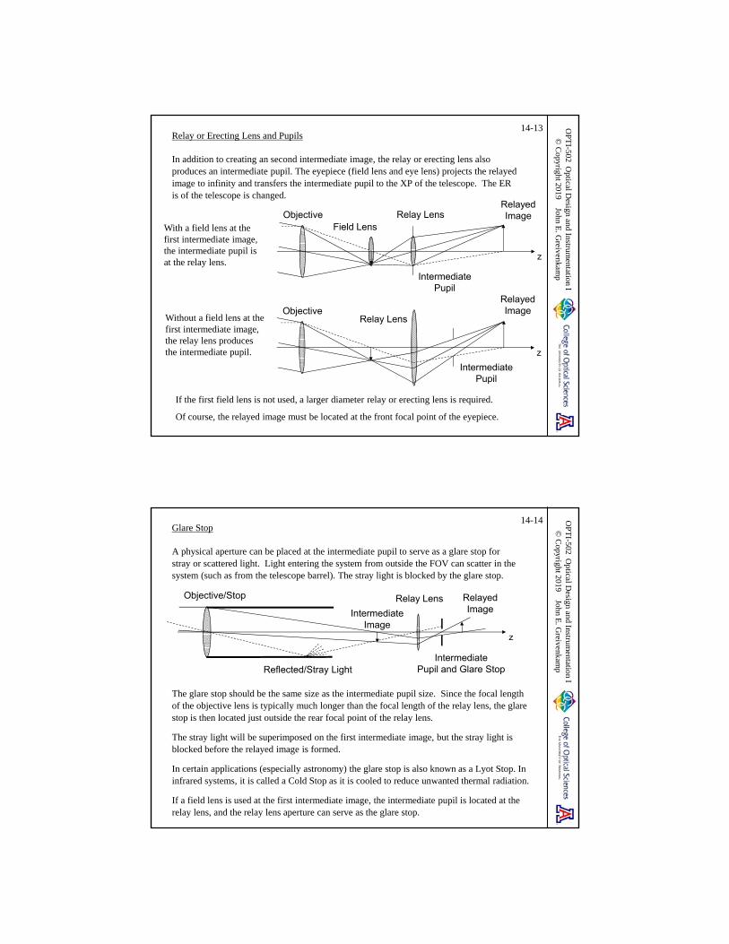
14-8TIR Limit – Glass Choice
Limiting f/#
BK7 n = 1.517 5.02
BaK4 n = 1.569 3.38
F2 n = 1.620 2.56
BK7 prisms are found in older designs and lower cost systems.
Note that the optical quality of all of these glasses (transmission, stria, etc.) are all excellent.
Roof surfaces do not experience this loss of TIR because the resulting compound angles increase the angle of incidence beyond the critical angle.
0
2
4
6
8
10
12
14
16
1.45 1.5 1.55 1.6 1.65 1.7
index n
Lim
iting
f/#
BK7
BaK4F2
If the objective lens is faster than the limiting f/#, rays from the edge of the pupil will not experience TIR. For fast objective lenses, higher index glass must be used.

OP
TI-502 O
ptical Design and Instrum
entation I©
Copyright 2019 John E
. Greivenkam
p
14-9TIR Limit – Effect on Exit Pupil
The Porro Prism erecting system in a pair of binoculars can be thought of as four right angle prisms. If the objective lens used in the binoculars is faster than the TIR limit, portions of the XP are clipped.
At each reflection, the loss of TIR will clip an edge of the XP.
Each of the four reflections in a Porro Prism system will clip a different side of the XP. The final XP becomes squared-off.
In the regions of the pupil where TIR is lost, there will be some light in the pupil due to Fresnel reflections.
Objective
Porro PrismSystems
Eye Lenses
Nominal Exit Pupils
Objective
OP
TI-502 O
ptical Design and Instrum
entation I©
Copyright 2019 John E
. Greivenkam
p
14-10Relay or Erecting Lens
A relay or erecting lens inserted between the objective and the eye lens of the Keplerian telescope can correct the image orientation. The intermediate image formed by the objective is relayed to a second intermediate image. The second intermediate image is placed at the front focal point of the eyepiece. The re-imaging causes an image rotation of 180°, correcting the image orientation.
The net MP of the relayed Keplerian telescope is positive. The system MP equals the product of the magnification of the relay and the MP of the original Keplerian telescope.
z1h
2h
ObjectiveRelay Lens Eye Lens
EYEfRzRzOBJf
RR
R
zm
z
OBJR
R KR EYE
fzMP m MP
z f

OP
TI-502 O
ptical Design and Instrum
entation I©
Copyright 2019 John E
. Greivenkam
p
14-11Relay Lenses and Field Lenses
Field lenses can also be added at or near the intermediate images. A common arrangement is for each field lens to image the pupil into the following relay lens. All of the light collected by the objective is transferred down the optical system. The final field lens is part of the eyepiece.
The first field lens images the objective aperture into the relay aperture, transferring the entrance pupil to the relay lens. If the relay lens diameter is larger than this image, all of the light from an object point collected by the objective will be transferred to the second image. For an optical system used with the eye, the final field lens will not image the relay lens aperture into the eye lens, but rather to the exit pupil with the appropriate eye relief.
z
Objective RelayEyeLens
EYEfOBJf
Field Field XP
ER
OP
TI-502 O
ptical Design and Instrum
entation I©
Copyright 2019 John E
. Greivenkam
p
14-12Ray Bundle with Relay Lenses and Field Lenses
The first field lens images the objective/stop into the relay lens. An intermediate pupil is located at the relay lens.
The relay lens images the first intermediate image to the second intermediate image. This second intermediate image must be located at the front focal point of the eyepiece. The eyepiece is the combination of the second field lens and the eye lens.
The eyepiece also images the intermediate pupil into image space to create the exit pupil and the eye relief.
In this example, the intermediate pupil is smaller than the relay lens diameter. A relay lens with a diameter smaller than that shown could be used. However in many situations, all of the lenses (except the objective) are mounted in the same tube and have approximately the same diameters.
z
Objective RelayEyeLens
EYEfOBJf
Field Field XP
ER
Marginal Ray
OP
TI-502 O
ptical Design and Instrum
entation I©
Copyright 2019 John E
. Greivenkam
p
14-13Relay or Erecting Lens and Pupils
In addition to creating an second intermediate image, the relay or erecting lens also produces an intermediate pupil. The eyepiece (field lens and eye lens) projects the relayed image to infinity and transfers the intermediate pupil to the XP of the telescope. The ER is of the telescope is changed.
If the first field lens is not used, a larger diameter relay or erecting lens is required.
Of course, the relayed image must be located at the front focal point of the eyepiece.
ObjectiveRelay Lens
IntermediatePupil
RelayedImage
z
With a field lens at the first intermediate image, the intermediate pupil is at the relay lens.
Without a field lens at the first intermediate image, the relay lens produces the intermediate pupil.
Objective Relay LensField Lens
IntermediatePupil
RelayedImage
z
Glare Stop
A physical aperture can be placed at the intermediate pupil to serve as a glare stop for stray or scattered light. Light entering the system from outside the FOV can scatter in the system (such as from the telescope barrel). The stray light is blocked by the glare stop.
OP
TI-502 O
ptical Design and Instrum
entation I©
Copyright 2019 John E
. Greivenkam
p
14-14
The glare stop should be the same size as the intermediate pupil size. Since the focal length of the objective lens is typically much longer than the focal length of the relay lens, the glare stop is then located just outside the rear focal point of the relay lens.
The stray light will be superimposed on the first intermediate image, but the stray light is blocked before the relayed image is formed.
In certain applications (especially astronomy) the glare stop is also known as a Lyot Stop. In infrared systems, it is called a Cold Stop as it is cooled to reduce unwanted thermal radiation.
If a field lens is used at the first intermediate image, the intermediate pupil is located at the relay lens, and the relay lens aperture can serve as the glare stop.
Objective/Stop Relay Lens
IntermediatePupil and Glare Stop
RelayedImage
z
Reflected/Stray Light
IntermediateImage

FOV and the Relay Lens
In many systems, the relay works at approximately 1:1 conjugates or magnification. The object distance for the relay lens is then twice the focal length of the relay lens. This situation limits the FOV of the system and/or requires a large diameter relay lens.
The FOV is limited by vignetting at the relay lens.
A field stop and a glare stop can be added to this system. The glare stop would be located where the chief ray crosses the axis following the relay lens.
Since the FOV is small, adding a field lens at the first intermediate image plane may only provide a moderate increase in the FOV of the system.
OP
TI-502 O
ptical Design and Instrum
entation I©
Copyright 2019 John E
. Greivenkam
p
14-15
fObjective 2fRelay 2fRelay
ObjectiveRelay Lens
Erecting Couplet
Increased FOV can be obtained by using an erecting couplet. The single relay lens is split into a pair of elements that provide the 1:1 imaging for the relayed image.
Since the distance between the first intermediate image and the first element of the couplet is the focal length of one of the relay elements, the cone of light from the intermediate image has less distance to expand. A significantly larger intermediate image and FOV is supported.
The FOV is still limited by vignetting at the relay lens.
OP
TI-502 O
ptical Design and Instrum
entation I©
Copyright 2019 John E
. Greivenkam
p
14-16
fRelayfObjective 2fRelay fRelay
Objective
Erecting or Relay Couplet
The erecting couplet shown has the same diameter as the single relay lens of the previous slide.

Erecting Couplet - Pupils
An intermediate pupil is formed between the two relay elements, and a glare stop may be placed at this location. The second relay element will produce a virtual image of the intermediate pupil that is reimaged by the eyepiece to produce the exit pupil and eye relief.
The common configuration is for the two elements to be separated by twice the focal length of a single element. Note that the system length has not changed as the separation between the two intermediate images remains .
The magnification provided by the erecting couplet is independent of the relay element separation. Changing this separation will change the distance between the intermediate pupil (glare stop) and the second relay element which moves the location of the final intermediate pupil produced by the erecting couplet. Varying this separation allows the location of the exit pupil to be adjusted to produce the desired value for the eye relief.
OP
TI-502 O
ptical Design and Instrum
entation I©
Copyright 2019 John E
. Greivenkam
p
14-17
Relay4f
fRelayfObjective 2fRelay fRelay
GlareStop
Objective
Erecting or Relay Couplet
OP
TI-502 O
ptical Design and Instrum
entation I©
Copyright 2019 John E
. Greivenkam
p
14-18Multiple Relays
Multiple relay lenses can be used to transfer the image over a long distance. Examples include periscopes, endoscopes and borescopes.
z
ObjectiveRelay
OBJf
Field Field Relay Field
A B C D E
The image is transferred from field lens to field lens:Lens A images the objective aperture into Lens BLens B images Lens A into Lens CLens C images Lens B into Lens D, etc.
The entrance pupil is imaged into each relay lens, and the image passes through without vignetting. There is no light loss except for transmission losses.
Starting with Lens B, a series of 1:1 imaging systems is often used. All of the lenses will have the same focal length and diameter. The relay system is completed with an eye lens or eyepiece. The final image can also be placed on an detector array.

14-19A Brief History of the Telescope
September 25, 1608
Hans Lipperhay was provided a letter of introduction in order to present his invention to the States-General in The Hague of the Netherlands for the purpose of obtaining a patent:
“a certain device by means of which all things at a very great distance can be seen as if they were nearby, by looking through glasses…”
1608: Dutch (or Galilean) Telescope
Lipperhay
1570-1619, German-Dutch
EYEfOBJf
OBJ EYEt f f • Erect image• Usually a low magnification• Often short and compact• Small field of view
OP
TI-502 O
ptical Design and Instrum
entation I©
Copyright 2019 John E
. Greivenkam
p
14-20Lipperhay’s Patent Application – September 25, 1608
October 2, 1608
Hans Lipperhay receives a request from the States-General “to ascertain … whether he could improve it so that one could look through it with both eyes.”
October 4, 1608
Committee is formed “for the purpose of examining and trying the instrument in question on the tower of the quarters of His Excellency” and “to negotiate with the inventor about the fabrication, within one year, of six such instruments made of rock crystal.”
December 15, 1608
Members of the committee report “that they have seen the instrument for seeing far with two eyes, invented by the spectacle-maker Lipperhay, and have found the same to be good.”
However, “since it is evident that several others have the knowledge of the invention for seeing far, the requested patent be denied the petitioner,…”
It is interesting to note that the development of binoculars began almost concurrently with the development of the telescope.
OP
TI-502 O
ptical Design and Instrum
entation I©
Copyright 2019 John E
. Greivenkam
p

Galileo’s Telescopes14-21
Galileo Galilei used a long high-magnification version of this design for his famous astronomical observations.
Galileo produced his first telescopes in 1609 (3-10X) with later improved telescopes with magnifications up to 20-30X. In 1610, he published his observations on the moon, the moons of Jupiter and the constellations and the Milky Way (Starry Messenger). Other observations included the rings of Saturn, the phases of Venus and sunspots.
Galileo; 1564-1642, Italian
This 21X telescope from 1609-10 has a plano-convex objective lens with diameter of 37 mm, an aperture of 15 mm, and a focal length of 980 mm. The telescope is 927 mm long with a field of view of 15 arc min.
OP
TI-502 O
ptical Design and Instrum
entation I©
Copyright 2019 John E
. Greivenkam
p
Starry Messenger or Sidereal Messenger14-22 O
PT
I-502 Optical D
esign and Instrumentation I
© C
opyright 2019 John E. G
reivenkamp

14-23A Brief History of the Telescope
1611: Astronomical (or Keplerian) Telescope
Proposed by Johannes Kepler in 1611Christoph Scheiner constructs first Keplerian telescope in 1617
• Inverted Image• Higher magnification• Longer length• Good field of view
EYEfOBJf
OBJ EYEt f f
Kepler; 1571-1630, German
OP
TI-502 O
ptical Design and Instrum
entation I©
Copyright 2019 John E
. Greivenkam
pO
PT
I-502 Optical D
esign and Instrumentation I
© C
opyright 2019 John E. G
reivenkamp
14-24
Circa 1635: Christoph Scheiner introduces a single erecting lens to produce an erect image.
Scheiner Erecting System or “Two-Lens Eyepiece”
The field of view is limited by the diameter of the erecting lens.
A Brief History of the Telescope
fObjective 2fRelay 2fRelay fEye
ExitPupil
Objective Erecting or Relay Lens Eye Lens
Scheiner; 1573-1650, German-Austrian

OP
TI-502 O
ptical Design and Instrum
entation I©
Copyright 2019 John E
. Greivenkam
p
14-25
1645: Anton Maria Schyrle de Rheita (1604-1660) used a two element erecting couplet to produce a practical terrestrial telescope with an erect image and acceptable magnification and field of view.
Schyrle Erecting System or “Three-Lens Eyepiece”
Note the presence of a glare stop between the two erector lenses.
A Brief History of the Telescope
fRelayfObjective 2fRelay fRelay fEye
GlareStop
FieldStop
ExitPupil
Objective Erecting or Relay Couplet Eye Lens
OP
TI-502 O
ptical Design and Instrum
entation I©
Copyright 2019 John E
. Greivenkam
p
14-26
1662: Christian Huygens invents the two lens eyepiece incorporating both an eye lens and a field lens.
Schyrle-Huygens Erecting System or “Four-Lens Eyepiece”
A Brief History of the Telescope
fRelayfObjective 2fRelay fEye
GlareStop
FieldStop
ExitPupil
Objective
Eye Piece
Erecting or Relay Couplet
FieldLens
EyeLens
In some telescopes, an additional field lens was inserted at or near the first intermediate image resulting in a five-lens eyepiece.
Huygens; 1629-1695, Dutch

OP
TI-502 O
ptical Design and Instrum
entation I©
Copyright 2019 John E
. Greivenkam
p
14-27
There is some evidence that the four-lens eyepiece was in use in the late 1600s, however it fell out of favor until the mid-1700s.
While there were improvements to follow, most notably the achromatic objective in the mid-1700s, the modern design form of the terrestrial refracting telescope was firmly in place by this time.
The use of brass tubes also began in the mid-1700s.
The vast majority of telescopes produced were not intended for astronomical use, but for nautical and military purposes.
A Brief History of the Telescope
OP
TI-502 O
ptical Design and Instrum
entation I©
Copyright 2019 John E
. Greivenkam
p
14-28Microscopes
The compound microscope is a sophisticated magnifier which presents an enlarged image of nearby object to the eye. It consists of an objective plus an eyepiece or ocular.
The visual magnification is the product of the lateral magnification of the objective and the MP of the eyepiece.
hz
h
Objective
XP
Image of h
Oz Oz ER
EYEEyepiece MP
EYEfOBJf
F
OTL
OOBJ
O
zm
z
250EYE
EYE
MPf
mm
250OV OBJ EYE
O EYE
zm m MP
z f
mm
Note that the visual magnification is negative (zO is negative).

OP
TI-502 O
ptical Design and Instrum
entation I©
Copyright 2019 John E
. Greivenkam
p
14-29Optical Tube Length and NA
The optical tube length OTL of a microscope is defined as the distance from the rear focal point of the objective to the front focal point of the eyepiece (intermediate image). Standard values for the OTL are 160 mm and 215 mm. A relaxed eye (image at infinity) is assumed. The OTL is a Newtonian image distance:
F
E
zm
f
OBJOBJ
OTLm
f
250V
OBJ EYE
OTLm
f f
mm
The NA of a microscope objective is defined in object space by the half-angle of the accepted input ray bundle. Along with the objective magnification, the NA is inscribed on the objective barrel.
Microscope objectives are often telecentric in object space. The stop is placed at the rear focal point of the objective so that the magnification does not change with object defocus.
z
Objective
Oz OBJf
F
StopO
sinO ONA n
OP
TI-502 O
ptical Design and Instrum
entation I©
Copyright 2019 John E
. Greivenkam
p
14-30Microscope Terminology
The working distance WD is the distance from the object to the first element of the objective; can be less than 1 mm for high-power objectives.
The mechanical tube length is separation between the shoulder of the threaded mount of the objective and the end of the tube into which the eyepiece is inserted. Objectives and eyepieces must be used at their design conjugates and are not necessarily interchangeable between manufacturers.
A set of parfocal objectives have different magnifications, but the same shoulder height and the same shoulder-to-intermediate image distance. As parfocal objectives are interchanged with a rotating turret, the image changes magnification but remains in focus.
Biological objectives are aberration corrected assuming a cover glass between the object and the objective. The design of a metallurgical objective assumes no cover glass.
10X0.10
Sho
ulde
r H
eigh
t
WD

OP
TI-502 O
ptical Design and Instrum
entation I©
Copyright 2019 John E
. Greivenkam
p
14-31Infinity Corrected Objectives
Research-grade microscopes are usually designed using infinity corrected objectives. The object plane is the front focal plane of the objective, and a collimated beam results for each object point. There is no specific tube length, and an additional tube lens is used to produce the intermediate image presented to the eyepiece.
The intermediate image is presented to the microscope eyepiece. The magnification of the objective-tube lens combination is:
TUBEOBJ
OBJ
fm
f
OBJ- f OBJf IOTL TUBEf
z
Infinity CorrectedObjective Stop
Shown Object-Space Telecentric
Tube Lens
F h
h
Intermediate image: presented to the eyepiece
14-32Magnification of Infinity Corrected Objectives
/
/L OBJ
OBJL TUBE
TUBEOBJ
OBJ
y fum
u y f
fm
f
OBJ- f TUBEf
z
Infinity CorrectedObjective
Tube Lens
IntermediateImage
Object u u′yL
OBJ f TUBE-f
OP
TI-502 O
ptical Design and Instrum
entation I©
Copyright 2019 John E
. Greivenkam
p

OP
TI-502 O
ptical Design and Instrum
entation I©
Copyright 2019 John E
. Greivenkam
p
14-33Microscope Resolution
Rayleigh Criterion – the object separation that is just resolved with the NA of the objective:
.61 1.22 /#Wh fNA
Because of diffraction, there is a maximum visual magnification that is useful. The intermediate image separation at the Raleigh criterion is then:
OBJh m h
From the discussion of magnifiers, the MP of the eyepiece that is required to resolve two objects separated by h' (using the eye resolution of 1 arc min) is
.075 75 75EYE
OBJ
mm m mMP
h h m h
A maximum useful visual magnification for the microscope results:
230 .55Vm NA m
Magnification above this level yields no additional information about the object. The extra magnification is applied to further magnify the just resolved Airy discs, and is termed empty magnification. Some empty magnification may be used to ease the visual observation.
75 75
.61 /V OBJ EYE
m mm m MP
h NA
Magnification and Magnifying Power - Summary
Magnification of a Focal Imaging System:
Magnification of an Afocal Imaging System:
Magnifying Power of a Magnifier:
Magnifying Power of a Simple Telescope or Binoculars (Afocal):
Magnifying Power of a Relayed Keplerian Telescope:
Visual Magnification of a Microscope (Finite Tube):
Visual Magnification of a Microscope (Infinite Tube):
OP
TI-502 O
ptical Design and Instrum
entation I©
Copyright 2019 John E
. Greivenkam
p
14-34
/( , Gaussian Distances)
/
h z nm z z
h z n
2
1
fhm
h f
1
2
1 OBJ
EYE
ffMP
m f f
( , Gaussian Diatances)
OBJRR K R R
R EYE
fzMP m MP z z
z f
250 10
mmMP
f f
250( , Gaussian Distances)
OBJ
V OBJ EYE OBJ OBJOBJ EYE
z mmm m MP z z
z f
250
TUBE TUBEV EYE
OBJ OBJ EYE
f f mmm MP
f f f