50 g shock ni 9237 - national instruments · the ni 9237 can perform offset/null as well as shunt...
TRANSCRIPT

DATASHEET
NI 92374 AI, ±25 mV/V, 24 Bit, 50 kS/s/ch Simultaneous, Bridge Completion
• 4 channels, 50 kS/s per channel simultaneous AI• ±25 mV/V input range, 24-bit resolution• Programmable half- and full-bridge completion
with up to 10 V internal excitation• 60 VDC, Category I bank isolation• RJ50 or D-SUB connectivity options• -40 °C to 70 °C operating range, 5 g vibration,
50 g shock
The NI 9237 simultaneous bridge module for use with CompactDAQ and CompactRIOcontains all the signal conditioning required to power and measure up to four bridge-basedsensors simultaneously. The four RJ50 jacks provide direct connectivity to most torque or loadcells and offer custom cable solutions with minimal tools. The high sampling rate andbandwidth of the NI 9237 offer a high-quality, high-speed strain or load measurement systemwith zero interchannel phase delay. With 60 VDC isolation and 1,000 Vrms transient isolation,the NI 9237 has high-common-mode noise rejection and increased safety for both the operatorand test system.
The NI 9237 can perform offset/null as well as shunt calibration and remote sense, making themodule the best choice for strain and bridge measurements.
The NI 9944 and NI 9945 are accessories for use with quarter-bridge sensors. Theseaccessories have a female RJ50 connector on one end and screw terminals on the other end.

C SERIES SIMULTANEOUS BRIDGE MODULE COMPARISON
Model Channels SampleRate
Resolution Connectivity SimultaneousSupported Bridges
NI 9218
NI 9219
NI 9235
NI 9236
NI 9237
51.2 kS/s/ch
100 S/s/ch
10 kS/s/ch
10 kS/s/ch
50 kS/s/ch
24 bits
24 bits
24 bits
24 bits
24 bits
Quarter, Half, Full
Quarter, Half, Full
120 Ω Quarter Bridge
350 Ω Quarter Bridge
Quarter, Half, Full
LEMO,9-pin DSUB
SpringTerminal
SpringTerminal
SpringTerminal
RJ-50,DSUB
2
4
8
8
4
NI C Series Overview
NI provides more than 100 C Series modules for measurement, control, and communicationapplications. C Series modules can connect to any sensor or bus and allow for high-accuracymeasurements that meet the demands of advanced data acquisition and control applications.• Measurement-specific signal conditioning that connects to an array of sensors and signals• Isolation options such as bank-to-bank, channel-to-channel, and channel-to-earth ground• -40 °C to 70 °C temperature range to meet a variety of application and environmental
needs• Hot-swappable
The majority of C Series modules are supported in both CompactRIO and CompactDAQplatforms and you can move modules from one platform to the other with no modification.
2 | ni.com | NI 9237 Datasheet

CompactRIO
CompactRIO combines an open-embedded architecturewith small size, extreme ruggedness, and C Seriesmodules in a platform powered by the NI LabVIEWreconfigurable I/O (RIO) architecture. Each systemcontains an FPGA for custom timing, triggering, andprocessing with a wide array of available modular I/O tomeet any embedded application requirement.
CompactDAQ
CompactDAQ is a portable, rugged data acquisition platformthat integrates connectivity, data acquisition, and signalconditioning into modular I/O for directly interfacing to anysensor or signal. Using CompactDAQ with LabVIEW, youcan easily customize how you acquire, analyze, visualize,and manage your measurement data.
Software
LabVIEW Professional Development System for Windows
• Use advanced software tools for large project development• Generate code automatically using DAQ Assistant and Instrument
I/O Assistant• Use advanced measurement analysis and digital signal processing• Take advantage of open connectivity with DLLs, ActiveX,
and .NET objects• Build DLLs, executables, and MSI installers
NI LabVIEW FPGA Module
• Design FPGA applications for NI RIO hardware• Program with the same graphical environment used for desktop and
real-time applications• Execute control algorithms with loop rates up to 300 MHz• Implement custom timing and triggering logic, digital protocols, and
DSP algorithms• Incorporate existing HDL code and third-party IP including Xilinx IP
generator functions• Purchase as part of the LabVIEW Embedded Control and Monitoring
Suite
NI 9237 Datasheet | © National Instruments | 3

NI LabVIEW Real-Time Module
• Design deterministic real-time applications with LabVIEWgraphical programming
• Download to dedicated NI or third-party hardware for reliableexecution and a wide selection of I/O
• Take advantage of built-in PID control, signal processing, andanalysis functions
• Automatically take advantage of multicore CPUs or setprocessor affinity manually
• Take advantage of real-time OS, development and debuggingsupport, and board support
• Purchase individually or as part of a LabVIEW suite
CircuitryEach channel on the NI 9237 has an independent 24-bit ADC and an input amplifier thatenable you to sample signals from all four channels simultaneously.
The NI 9237 is isolated from earth ground. However, the individual channels are not isolatedfrom each other. The EX+, EX-, and T- signals are common among all channels. You canconnect the NI 9237 to a device that is biased at any voltage within the NI 9237 rejectionrange of earth ground.
Figure 1. Input Circuitry for One Channel of the NI 9237
+ –AI+
EX+
RS+Reference
InputAI–
EX–
RS–
SC
SCNI 9237
Connection Options to Correct for Resistance ErrorsWiring resistance can create errors in bridge circuits. The NI 9237 provides two mechanismsto correct for these errors: remote sensing and shunt calibration.
Remote SensingRemote sensing continuously and automatically corrects for errors in excitation leads, andgenerally is most appropriate for half- and full-bridge sensors.
Long wire and small gauge wire have greater resistance, which can result in gain error. Theresistance in the wires that connect the excitation voltage to the bridge causes a voltage drop,
4 | ni.com | NI 9237 Datasheet

which is a source of gain error. The NI 9237 includes remote sensing to compensate for thisgain error. Connect remote sense wires to the points where the excitation voltage wiresconnect to the bridge circuit. Refer to the following figure for an illustration of how to connectremote sense wires to the NI 9237.
Figure 2. Connecting Remote Sense Wires to the NI 9237
EX+
EX–
RS+
RS–
Rbridge
Rlead
Rlead
Rbridge Rbridge
Rbridge
NI 9237
AI–AI+
The actual bridge excitation voltage is smaller than the voltage at the EX+ and EX- leads. Ifyou do not use remote sensing of the actual bridge voltage, the resulting gain error is:
for half‐bridge sensors and2 ⋅ for full‐bridge sensors.If you connect the remote sense signals directly to the bridge resistors, the NI 9237 senses theactual bridge voltage and eliminates the gain errors caused by the resistance of the EX+ andEX- leads.
Shunt CalibrationShunt calibration can correct for errors from the resistance of both the excitation wiring andwiring in the individual resistors of the bridge. Remote sensing corrects for resistances fromthe EX pins on the NI 9237 to the sensor, and shunt calibration corrects for these errors and forerrors caused by wire resistance within an arm of the bridge. Shunt calibration is most usefulwith quarter-bridge sensors because there may be significant resistance in the wiring to theactive resistor in the bridge.
The NI 9237 shunt calibration circuitry consists of a precision resistor and a software-controlled switch. Refer to the software help for information about enabling the shuntcalibration switch for the NI 9237.
Shunt calibration involves simulating the input of strain by changing the resistance of an armin the bridge by some known amount. This is accomplished by shunting, or connecting, a largeresistor of known value across one arm of the bridge, creating a known strain-induced changein resistance. You can then measure the output of the bridge and compare it to the expectedvoltage value. You can use the results to correct gain errors in the entire measurement path, orto simply verify general operation to gain confidence in the setup.
NI 9237 Datasheet | © National Instruments | 5
Use a stable signal, which is typically the unloaded state of the sensor, first with the shuntcalibration switch off and then again with the switch on. The difference in these twomeasurements provides an indication of the gain errors from wiring resistances. You candesign the software application to correct subsequent readings for this gain error.
Excitation VoltagesYou can program the NI 9237 to supply 2.5 V, 3.3 V, 5 V, or 10 V of excitation voltage. Themaximum excitation power for internal excitation is 150 mW.
Note Unless you supply external excitation voltage, NI recommends that you setthe excitation voltage to a value that keeps the total power below 150 mW. TheNI 9237 automatically reduces internal excitation voltages as needed to stay below150 mW total power.
Use the following equation to calculate the power of a single bridge:
= 2where R is the total resistance of the bridge.
For a quarter or half bridge, R is equal to two times the resistance of each element. For a fullbridge, R is equal to the resistance of each element.
The 150 mW limit allows you to power half and full bridges as follows:• Four 350 Ω half bridges at 5.0 V• Four 350 Ω full bridges at 3.3 V• Four 120 Ω half bridges at 2.5 V
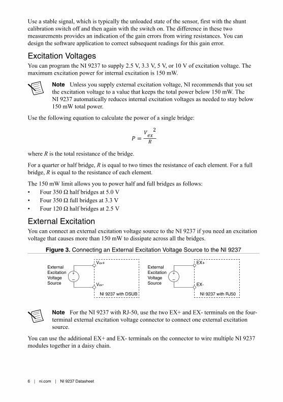
External ExcitationYou can connect an external excitation voltage source to the NI 9237 if you need an excitationvoltage that causes more than 150 mW to dissipate across all the bridges.
Figure 3. Connecting an External Excitation Voltage Source to the NI 9237
Vex+
Vex-
NI 9237 with DSUB
+
–
External ExcitationVoltage Source
EX+
EX-
NI 9237 with RJ50
+
–
External ExcitationVoltage Source
Note For the NI 9237 with RJ-50, use the two EX+ and EX- terminals on the four-terminal external excitation voltage connector to connect one external excitationsource.
You can use the additional EX+ and EX- terminals on the connector to wire multiple NI 9237modules together in a daisy chain.
6 | ni.com | NI 9237 Datasheet

FilteringThe NI 9237 uses a combination of analog and digital filtering to provide an accuraterepresentation of in-band signals and reject out-of-band signals. The filters discriminatebetween signals based on the frequency range, or bandwidth, of the signal. The three importantbandwidths to consider are the passband, the stopband, and the anti-imaging bandwidth.
The NI 9237 represents signals within the passband, as quantified primarily by passband rippleand phase nonlinearity. All signals that appear in the alias-free bandwidth are either unaliasedsignals or signals that have been filtered by at least the amount of the stopband rejection.
PassbandThe signals within the passband have frequency-dependent gain or attenuation. The smallamount of variation in gain with respect to frequency is called the passband flatness. Thedigital filters of the NI 9237 adjust the frequency range of the passband to match the data rate.Therefore, the amount of gain or attenuation at a given frequency depends on the data rate.
Figure 4. Typical Passband Flatness for the NI 9237
Frequency/Data Rate
0.50.4
0.025
0.000
–0.025
–0.0500.30.20.10
Gai
n (d
B)
StopbandThe filter significantly attenuates all signals above the stopband frequency. The primary goalof the filter is to prevent aliasing. Therefore, the stopband frequency scales precisely with thedata rate. The stopband rejection is the minimum amount of attenuation applied by the filter toall signals with frequencies within the stopband.
Alias-Free BandwidthAny signals that appear in the alias-free bandwidth are not aliased artifacts of signals at ahigher frequency. The alias-free bandwidth is defined by the ability of the filter to rejectfrequencies above the stopband frequency. The alias-free bandwidth is equal to the data rateminus the stopband frequency.
NI 9237 Datasheet | © National Instruments | 7
Data RatesThe frequency of a master timebase (fM) controls the data rate (fs) of the NI 9237. The NI 9237includes an internal master timebase with a frequency of 12.8 MHz, but the module also canaccept an external master timebase or export its own master timebase. To synchronize the datarate of an NI 9237 with other modules that use master timebases to control sampling, all of themodules must share a single master timebase source.
The following equation provides the available data rates of the NI 9237:
= ÷ 256where n is any integer from 1 to 31.
However, the data rate must remain within the appropriate data rate range. When using theinternal master timebase of 12.8 MHz, the result is data rates of 50 kS/s, 25 kS/s, 16.667 kS/s,and so on down to 1.613 kS/s depending on the value of n. When using an external timebasewith a frequency other than 12.8 MHz, the NI 9237 has a different set of data rates.
Note The NI 9151 R Series Expansion chassis does not support sharing timebasesbetween modules.
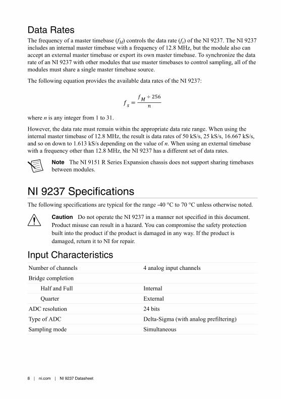
NI 9237 SpecificationsThe following specifications are typical for the range -40 °C to 70 °C unless otherwise noted.
Caution Do not operate the NI 9237 in a manner not specified in this document.Product misuse can result in a hazard. You can compromise the safety protectionbuilt into the product if the product is damaged in any way. If the product isdamaged, return it to NI for repair.
Input CharacteristicsNumber of channels 4 analog input channels
Bridge completion
Half and Full Internal
Quarter External
ADC resolution 24 bits
Type of ADC Delta-Sigma (with analog prefiltering)
Sampling mode Simultaneous
8 | ni.com | NI 9237 Datasheet

Internal master timebase (ƒM)
Frequency 12.8 MHz
Accuracy ±100 ppm maximum
Data rate range (ƒs) using internal master timebase
Minimum 1.613 kS/s
Maximum 50 kS/s
Data rate range (ƒs) using external master timebase
Minimum 391 S/s
Maximum 51.36 kS/s
Data rates (ƒs) (ƒM ÷ 256) ÷ n, where n = 1, 2, …, 31
Typical input range ±25 mV/V
Scaling coefficient 2.9802 nV/V per LSB
Overvoltage protection between any two pins ±30 V
Table 1. Accuracy
Measurement Conditions1 Percent of Reading(Gain Error2)
Percent of Range3
(Offset Error)
Calibrated Typical (25 °C, ±5 °C) 0.05% 0.05%
Maximum (– 40 to 70 °C) 0.20% 0.25%
Uncalibrated4 Typical (25 °C, ±5 °C) 0.20% 0.10%
Maximum (– 40 to 70 °C) 0.55% 0.35%
Gain drift 10 ppm/°C maximum
Offset drift
2.5 V excitation 0.6 µV/V per °C
3.3 V excitation 0.5 µV/V per °C
5 V excitation 0.3 µV/V per °C
10 V excitation 0.2 µV/V per °C
1 Before offset null or shunt calibration.2 Applies at a data rate of 50 kS/s. Lower data rates can have up to 0.20% of reading additional gain
error.3 Range equals 25 mV/V.4 Uncalibrated accuracy refers to the accuracy achieved when acquiring data in raw or unscaled
modes and in which calibration constants that are stored in the module are not applied to the data.
NI 9237 Datasheet | © National Instruments | 9

Half-bridge completion
Tolerance ±1200 µV/V maximum
Drift 1.5 µV/V per °C
Table 2. Channel-to-Channel Matching (Calibrated)
Input Signal Frequency (ƒin) Gain Phase
Typical Maximum Maximum
0 to 1 kHz 0.15% 0.3%0.125°/kHz · ƒin
1 to 20 kHz 0.4% 1.1%
Phase nonlinearity
ƒin = 0 to 1 kHz <0.001°
ƒin = 0 to 20 kHz ±0.1°
Input delay (40 + 5/512)/ƒs + 4.5 µs
Passband
Frequency 0.45 · ƒs
Flatness 0.1 dB maximum
Stopband
Frequency 0.55 · ƒs
Rejection 100 dB
Alias-free bandwidth 0.45 · ƒs
Oversample rate 64 · ƒs
Rejection at oversample rate5
ƒs = 10 kS/s 60 dB @ 640 kHz
ƒs = 50 kS/s 90 dB @ 3.2 MHz
Common-mode voltage,all signals to earth ground
±60 VDC
Common-mode voltage range,with respect to EX-
±1 V from the midpoint of the excitationvoltage
5 Rejection by analog prefilter of signal frequencies at oversample rate.
10 | ni.com | NI 9237 Datasheet

CMRR
Relative to earth ground6 (ƒin = 0 to 60Hz)
140 dB
Relative to EX– (ƒin = 0 to 1 kHz) 85 dB
SFDR (1 kHz, –60 dBFS) 115 dB
Total Harmonic Distortion (THD)
1 kHz, –20 dBFS –95 dB
8 kHz, –20 dBFS –95 dB
Table 3. Input Noise
ExcitationVoltage
Density, (nV/Vrms per1 Hz
Total, ƒin = 0 to1 kHz (nV/Vrms)
Total, ƒin = 0 to 25 kHz (µV/Vrms)
Full Bridge Full Bridge Full Bridge Half Bridge
2.5 V 8 250 1.3 1.6
3.3 V 6 190 1.0 1.2
5 V 4 130 0.6 0.8
10 V 2 65 0.3 0.5
Excitation noise 100 µVrms
Crosstalk (not including cable effects)
ƒin = 1 kHz 110 dB
ƒin = 10 kHz 100 dB
Excitation
Internal voltage 2.5 V, 3.3 V, 5.0 V, 10.0 V
Internal power 150 mW maximum
External voltage 2 V to 10 V
Shunt calibration
Resistance 100 kΩ
6 Measured with a balanced cable on the NI 9237 with RJ-50 and with no cable on theNI 9237 with DSUB. Shielded cables that are not twisted-pair may be significantly unbalanced,which can impact CMRR performance. To improve the balance of shielded cables, NI recommendstwisting together the AI+/AI– pair, the RS+/RS– pair, and the EX+/EX– pair.
NI 9237 Datasheet | © National Instruments | 11

Resistor accuracy
25 °C ±110 Ω
– 40 °C to 70 °C ±200 Ω
MTBF
NI 9237 with RJ-50 603,359 hours at 25 °C; Bellcore Issue 2,Method 1, Case 3, Limited Part Stress Method
NI 9237 with DSUB 704,148 hours at 25 °C; Bellcore Issue 2,Method 1, Case 3, Limited Part Stress Method
Power RequirementsPower consumption from chassis
Active mode 740 mW maximum
Sleep mode 25 µW maximum
Thermal dissipation (at 70 °C)
Active mode 740 mW maximum
Sleep mode 25 µW maximum
Physical CharacteristicsIf you need to clean the module, wipe it with a dry towel.
Tip For two-dimensional drawings and three-dimensional models of the C Seriesmodule and connectors, visit ni.com/dimensions and search by module number.
Safety VoltagesConnect only voltages that are within the following limits.
Between any two pins ±30 V maximum
Isolation, channel-to-channel None
Isolation, channel-to-earth ground
Up to 3,000 m
Continuous 60 VDC, Measurement Category I
Withstand 1,000 Vrms, verified by a 5 s dielectricwithstand test
Up to 5,000 m
Continuous 60 VDC, Measurement Category I
Withstand 860 Vrms, verified by a 5 s dielectricwithstand test
12 | ni.com | NI 9237 Datasheet

Measurement Category I is for measurements performed on circuits not directly connected tothe electrical distribution system referred to as MAINS voltage. MAINS is a hazardous liveelectrical supply system that powers equipment. This category is for measurements of voltagesfrom specially protected secondary circuits. Such voltage measurements include signal levels,special equipment, limited-energy parts of equipment, circuits powered by regulated low-voltage sources, and electronics.
Caution Do not connect the NI 9237 to signals or use for measurements withinMeasurement Categories II, III, or IV.
Note Measurement Categories CAT I and CAT O are equivalent. These test andmeasurement circuits are not intended for direct connection to the MAINS buildinginstallations of Measurement Categories CAT II, CAT III, or CAT IV.
Hazardous LocationsU.S. (UL) Class I, Division 2, Groups A, B, C, D, T4;
Class I, Zone 2, AEx nA IIC T4
Canada (C-UL) Class I, Division 2, Groups A, B, C, D, T4;Class I, Zone 2, Ex nA IIC T4
Europe (ATEX) and International (IECEx) Ex nA IIC T4 Gc
Safety and Hazardous Locations StandardsThis product is designed to meet the requirements of the following electrical equipment safetystandards for measurement, control, and laboratory use:• IEC 61010-1, EN 61010-1• UL 61010-1, CSA 61010-1• EN 60079-0:2012, EN 60079-15:2010• IEC 60079-0: Ed 6, IEC 60079-15; Ed 4• UL 60079-0; Ed 5, UL 60079-15; Ed 3• CSA 60079-0:2011, CSA 60079-15:2012
Note For UL and other safety certifications, refer to the product label or the OnlineProduct Certification section.
Electromagnetic CompatibilityThis product meets the requirements of the following EMC standards for sensitive electricalequipment for measurement, control, and laboratory use:• EN 61326-2-1 (IEC 61326-2-1): Class A emissions; Industrial immunity• EN 55011 (CISPR 11): Group 1, Class A emissions• AS/NZS CISPR 11: Group 1, Class A emissions
NI 9237 Datasheet | © National Instruments | 13

• FCC 47 CFR Part 15B: Class A emissions• ICES-001: Class A emissions
Note In the United States (per FCC 47 CFR), Class A equipment is intended foruse in commercial, light-industrial, and heavy-industrial locations. In Europe,Canada, Australia and New Zealand (per CISPR 11) Class A equipment is intendedfor use only in heavy-industrial locations.
Note Group 1 equipment (per CISPR 11) is any industrial, scientific, or medicalequipment that does not intentionally generate radio frequency energy for thetreatment of material or inspection/analysis purposes.
Note For EMC declarations and certifications, and additional information, refer tothe Online Product Certification section.
CE Compliance This product meets the essential requirements of applicable European Directives, as follows:• 2014/35/EU; Low-Voltage Directive (safety)• 2014/30/EU; Electromagnetic Compatibility Directive (EMC)• 94/9/EC; Potentially Explosive Atmospheres (ATEX)
Online Product CertificationRefer to the product Declaration of Conformity (DoC) for additional regulatory complianceinformation. To obtain product certifications and the DoC for this product, visit ni.com/certification, search by model number or product line, and click the appropriate link in theCertification column.
Shock and VibrationTo meet these specifications, you must panel mount the system.
Operating vibration
Random (IEC 60068-2-64) 5 grms, 10 Hz to 500 Hz
Sinusoidal (IEC 60068-2-6) 5 g, 10 Hz to 500 Hz
Operating shock (IEC 60068-2-27) 30 g, 11 ms half sine; 50 g, 3 ms half sine;18 shocks at 6 orientations
14 | ni.com | NI 9237 Datasheet

EnvironmentalRefer to the manual for the chassis you are using for more information about meeting thesespecifications.
Operating temperature(IEC 60068-2-1, IEC 60068-2-2)
-40 °C to 70 °C
Storage temperature(IEC 60068-2-1, IEC 60068-2-2)
-40 °C to 85 °C
Ingress Protection
NI 9237 with RJ-50 IP30
NI 9237 with DSUB IP40
Operating humidity (IEC 60068-2-78) 10% RH to 90% RH, noncondensing
Storage humidity (IEC 60068-2-78) 5% RH to 95% RH, noncondensing
Pollution Degree 2
Maximum altitude 5,000 m
Indoor use only.
Environmental ManagementNI is committed to designing and manufacturing products in an environmentally responsiblemanner. NI recognizes that eliminating certain hazardous substances from our products isbeneficial to the environment and to NI customers.
For additional environmental information, refer to the Minimize Our Environmental Impactweb page at ni.com/environment. This page contains the environmental regulations anddirectives with which NI complies, as well as other environmental information not included inthis document.
Waste Electrical and Electronic Equipment (WEEE)EU Customers At the end of the product life cycle, all NI products must bedisposed of according to local laws and regulations. For more information abouthow to recycle NI products in your region, visit ni.com/environment/weee.
电子信息产品污染控制管理办法(中国 RoHS)中国客户 National Instruments 符合中国电子信息产品中限制使用某些有害物
质指令(RoHS)。关于 National Instruments 中国 RoHS 合规性信息,请登录
ni.com/environment/rohs_china。(For information about China RoHScompliance, go to ni.com/environment/rohs_china.)
NI 9237 Datasheet | © National Instruments | 15

CalibrationYou can obtain the calibration certificate and information about calibration services for theNI 9237 at ni.com/calibration.
Calibration interval 1 year
Refer to the NI Trademarks and Logo Guidelines at ni.com/trademarks for information on NI trademarks. Other product andcompany names mentioned herein are trademarks or trade names of their respective companies. For patents covering NIproducts/technology, refer to the appropriate location: Help»Patents in your software, the patents.txt file on your media, or theNational Instruments Patent Notice at ni.com/patents. You can find information about end-user license agreements (EULAs)and third-party legal notices in the readme file for your NI product. Refer to the Export Compliance Information at ni.com/legal/export-compliance for the NI global trade compliance policy and how to obtain relevant HTS codes, ECCNs, and otherimport/export data. NI MAKES NO EXPRESS OR IMPLIED WARRANTIES AS TO THE ACCURACY OF THE INFORMATIONCONTAINED HEREIN AND SHALL NOT BE LIABLE FOR ANY ERRORS. U.S. Government Customers: The data contained inthis manual was developed at private expense and is subject to the applicable limited rights and restricted data rights as set forthin FAR 52.227-14, DFAR 252.227-7014, and DFAR 252.227-7015.
© 2006—2015 National Instruments. All rights reserved.
374186A-02 Nov15