5 motionview / motionsolve fundamentals altair hw.pdf · 5 motionview / motionsolve fundamentals a...
TRANSCRIPT
87
MotionView / MotionSolve Fundamentals
5 MotionView / MotionSolve Fundamentals
A Multi-Body system study generally involves the following broad steps:
• Constructing Models
• Executing Solvers
• Post-Processing
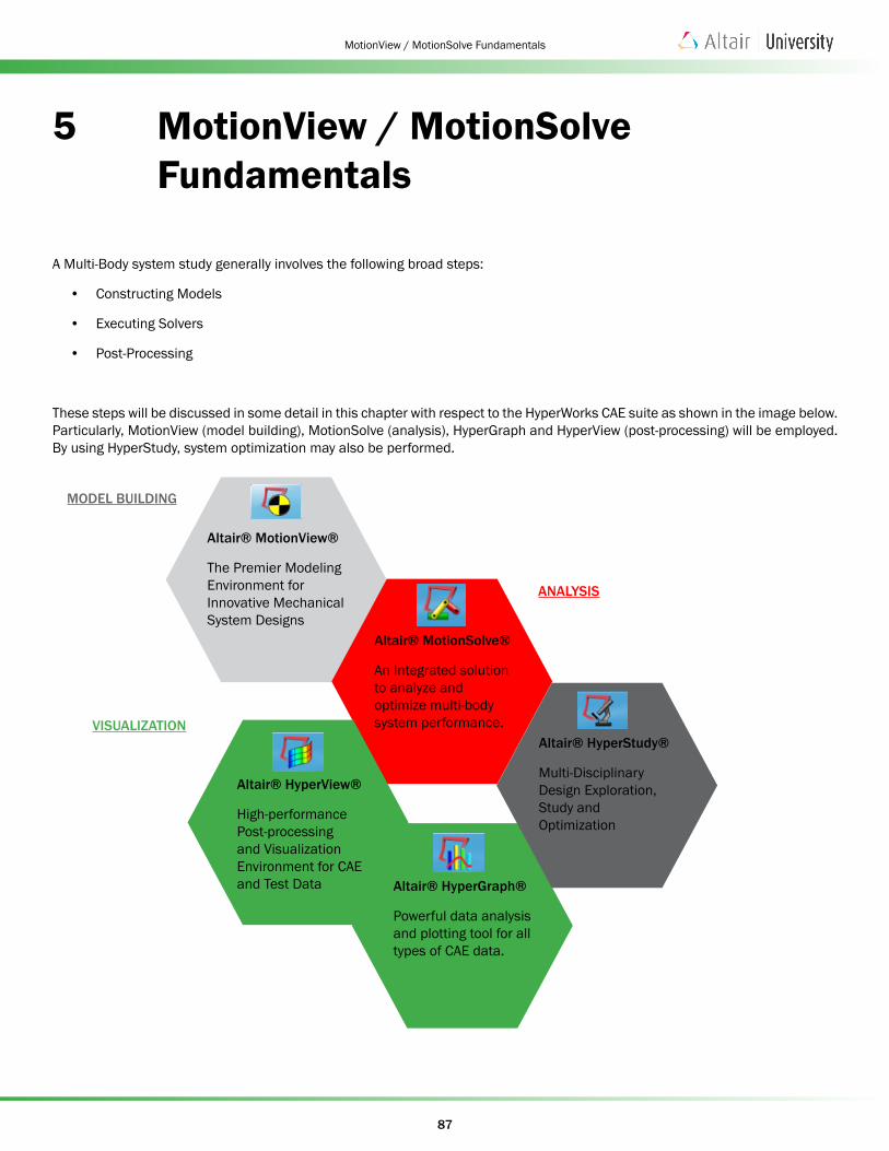
These steps will be discussed in some detail in this chapter with respect to the HyperWorks CAE suite as shown in the image below. Particularly, MotionView (model building), MotionSolve (analysis), HyperGraph and HyperView (post-processing) will be employed. By using HyperStudy, system optimization may also be performed.
MODEL BUILDING
ANALYSIS
VISUALIZATION
Altair® MotionView®
The Premier Modeling Environment for Innovative Mechanical System Designs
Altair® MotionSolve®
An Integrated solution to analyze and optimize multi-body system performance.
Altair® HyperGraph®
Powerful data analysis and plotting tool for all types of CAE data.
Altair® HyperStudy®
Multi-Disciplinary Design Exploration, Study and Optimization
Altair® HyperView®
High-performance Post-processing and Visualization Environment for CAE and Test Data
88
MotionView / MotionSolve Fundamentals
5.1 A General Overview On MBD (collection of videos) In this chapter of the book we have compiled a set of video which aim at providing a first introduction into MBD. Simply click on the image to start the video (or copy the path to your webbrowser).
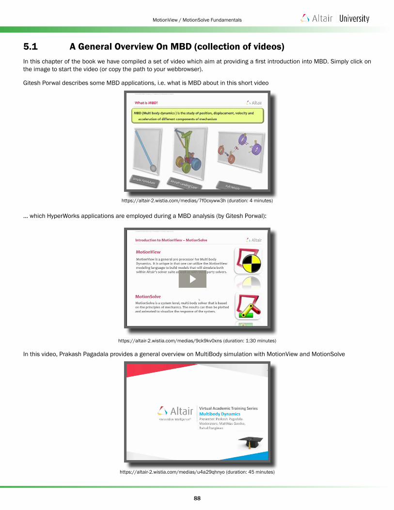
Gitesh Porwal describes some MBD applications, i.e. what is MBD about in this short video
https://altair-2.wistia.com/medias/7f0cxyww3h (duration: 4 minutes)
... which HyperWorks applications are employed during a MBD analysis (by Gitesh Porwal):
https://altair-2.wistia.com/medias/9ck9kv0xns (duration: 1:30 minutes)
In this video, Prakash Pagadala provides a general overview on MultiBody simulation with MotionView and MotionSolve
https://altair-2.wistia.com/medias/u4a29qhnyo (duration: 45 minutes)
89
MotionView / MotionSolve Fundamentals
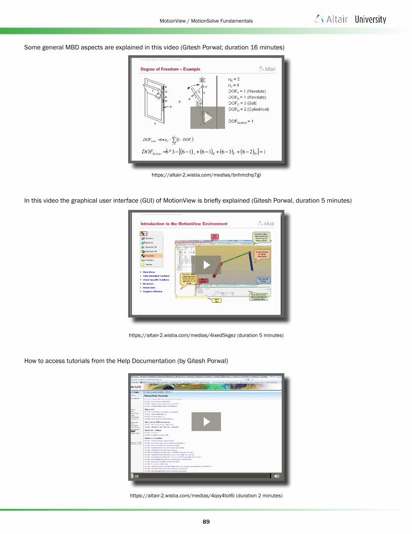
Some general MBD aspects are explained in this video (Gitesh Porwal; duration 16 minutes)
https://altair-2.wistia.com/medias/bnhmzhq7gi
In this video the graphical user interface (GUI) of MotionView is briefly explained (Gitesh Porwal, duration 5 minutes)
https://altair-2.wistia.com/medias/4ixed5kgez (duration 5 minutes)
How to access tutorials from the Help Documentation (by Gitesh Porwal)
https://altair-2.wistia.com/medias/4qxy4tol6i (duration 2 minutes)

90
MotionView / MotionSolve Fundamentals
High level discussion on points, bodies, joints by Gitesh Porwal (duration 10 minutes)
https://altair-2.wistia.com/medias/md5obe26oz
How to define MBD entities such as Points, Bodies, Graphics, Joints, Forces, Sensors, Output Requests, etc. in MotionView. The video was recorded by Gitesh Porwal (duration 31 minutes)
https://altair-2.wistia.com/medias/4d1pfrdthe
Some additional information about CAD Import in MotionView (by Gitesh Porwal, 5 minutes)
https://altair-2.wistia.com/medias/93tpq597xy
91
MotionView / MotionSolve Fundamentals
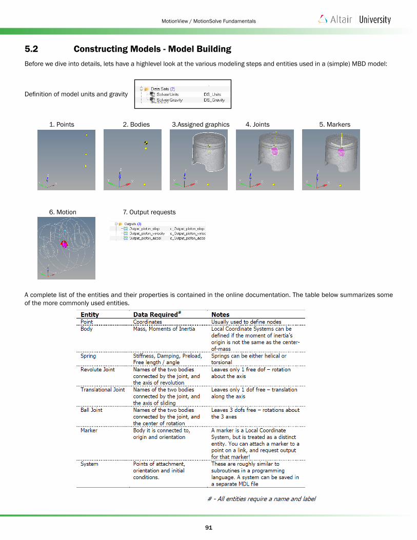
5.2 Constructing Models - Model BuildingBefore we dive into details, lets have a highlevel look at the various modeling steps and entities used in a (simple) MBD model:
Definition of model units and gravity
1. Points 2. Bodies 3.Assigned graphics 4. Joints 5. Markers
6. Motion 7. Output requests
A complete list of the entities and their properties is contained in the online documentation. The table below summarizes some of the more commonly used entities.
92
MotionView / MotionSolve Fundamentals
MBD models can be created using one or more of the following techniques:
1. Construct a model through the MotionView user interface. Entities can be added and deleted and their values set within the MotionView interface.
Note: In this book we will primarily focus on the interactive approach to:
• Create a model of a free body using MotionView
• Perform an analysis on the model using MotionSolve
• Post-process the MotionSolve results in HyperView & HyperGraph (the plot client)
Hence, option 2 and 3 listed below are just mentioned for your information.
2. Edit the MDL files directly. After you construct an MDL model, you can load it into MotionView at a later time for simulation use.
3. Assemble a model from the MDL library. A vehicle suspension and dynamics library is installed with MotionView by default which contains simple MDL modules. The library can be expanded or recreated for other mechanism types.
Let’s get introduced to the MotionView Graphical User Interface next.
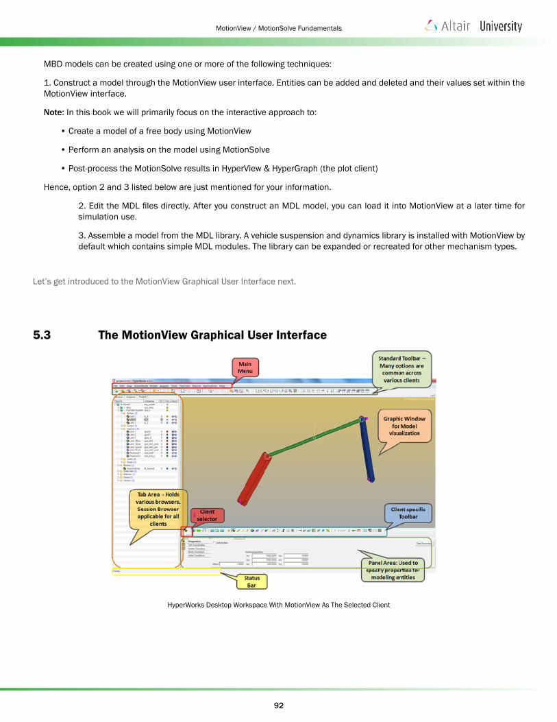
5.3 The MotionView Graphical User Interface
HyperWorks Desktop Workspace With MotionView As The Selected Client
93
MotionView / MotionSolve Fundamentals
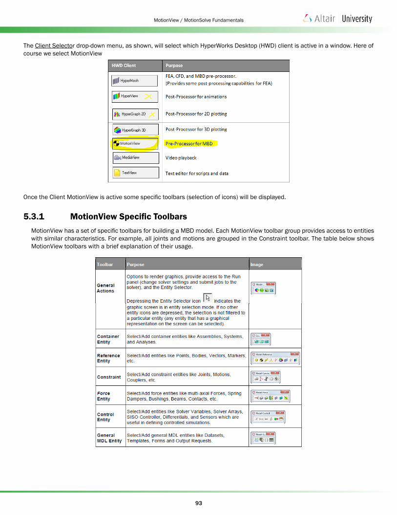
The Client Selector drop-down menu, as shown, will select which HyperWorks Desktop (HWD) client is active in a window. Here of course we select MotionView
Once the Client MotionView is active some specific toolbars (selection of icons) will be displayed.
5.3.1 MotionView Specific ToolbarsMotionView has a set of specific toolbars for building a MBD model. Each MotionView toolbar group provides access to entities with similar characteristics. For example, all joints and motions are grouped in the Constraint toolbar. The table below shows MotionView toolbars with a brief explanation of their usage.
94
MotionView / MotionSolve Fundamentals
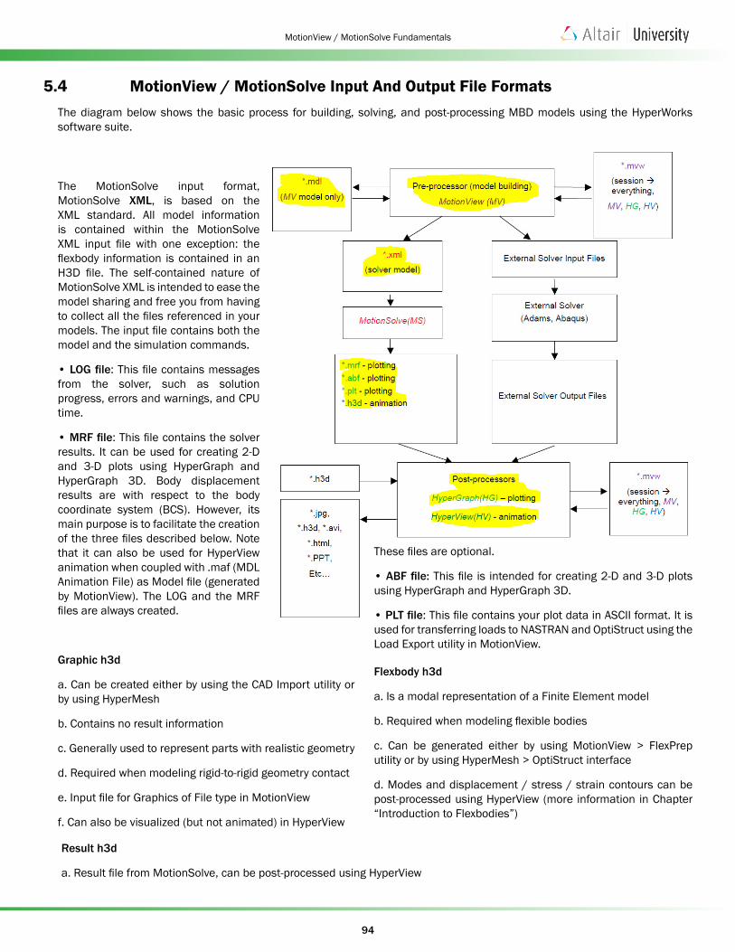
5.4 MotionView / MotionSolve Input And Output File FormatsThe diagram below shows the basic process for building, solving, and post-processing MBD models using the HyperWorks software suite.
The MotionSolve input format, MotionSolve XML, is based on the XML standard. All model information is contained within the MotionSolve XML input file with one exception: the flexbody information is contained in an H3D file. The self-contained nature of MotionSolve XML is intended to ease the model sharing and free you from having to collect all the files referenced in your models. The input file contains both the model and the simulation commands.
• LOG file: This file contains messages from the solver, such as solution progress, errors and warnings, and CPU time.
• MRF file: This file contains the solver results. It can be used for creating 2-D and 3-D plots using HyperGraph and HyperGraph 3D. Body displacement results are with respect to the body coordinate system (BCS). However, its main purpose is to facilitate the creation of the three files described below. Note that it can also be used for HyperView animation when coupled with .maf (MDL Animation File) as Model file (generated by MotionView). The LOG and the MRF files are always created.
Graphic h3d
a. Can be created either by using the CAD Import utility or by using HyperMesh
b. Contains no result information
c. Generally used to represent parts with realistic geometry
d. Required when modeling rigid-to-rigid geometry contact
e. Input file for Graphics of File type in MotionView
f. Can also be visualized (but not animated) in HyperView
These files are optional.
• ABF file: This file is intended for creating 2-D and 3-D plots using HyperGraph and HyperGraph 3D.
• PLT file: This file contains your plot data in ASCII format. It is used for transferring loads to NASTRAN and OptiStruct using the Load Export utility in MotionView.
Flexbody h3d
a. Is a modal representation of a Finite Element model
b. Required when modeling flexible bodies
c. Can be generated either by using MotionView > FlexPrep utility or by using HyperMesh > OptiStruct interface
d. Modes and displacement / stress / strain contours can be post-processed using HyperView (more information in Chapter “Introduction to Flexbodies”)
Result h3d
a. Result file from MotionSolve, can be post-processed using HyperView
95
MotionView / MotionSolve Fundamentals
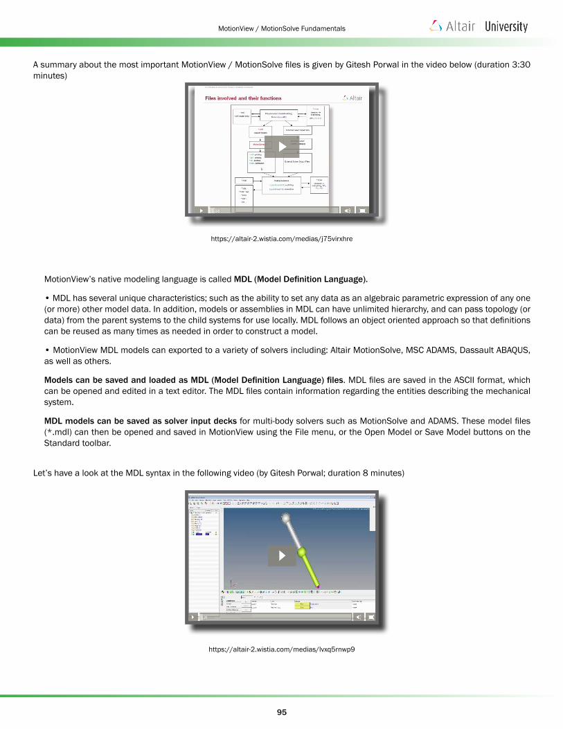
A summary about the most important MotionView / MotionSolve files is given by Gitesh Porwal in the video below (duration 3:30 minutes)
https://altair-2.wistia.com/medias/j75virxhre
MotionView’s native modeling language is called MDL (Model Definition Language).
• MDL has several unique characteristics; such as the ability to set any data as an algebraic parametric expression of any one (or more) other model data. In addition, models or assemblies in MDL can have unlimited hierarchy, and can pass topology (or data) from the parent systems to the child systems for use locally. MDL follows an object oriented approach so that definitions can be reused as many times as needed in order to construct a model.
• MotionView MDL models can exported to a variety of solvers including: Altair MotionSolve, MSC ADAMS, Dassault ABAQUS, as well as others.
Models can be saved and loaded as MDL (Model Definition Language) files. MDL files are saved in the ASCII format, which can be opened and edited in a text editor. The MDL files contain information regarding the entities describing the mechanical system.
MDL models can be saved as solver input decks for multi-body solvers such as MotionSolve and ADAMS. These model files (*.mdl) can then be opened and saved in MotionView using the File menu, or the Open Model or Save Model buttons on the Standard toolbar.
Let’s have a look at the MDL syntax in the following video (by Gitesh Porwal; duration 8 minutes)
https://altair-2.wistia.com/medias/lvxq5rnwp9
96
MotionView / MotionSolve Fundamentals
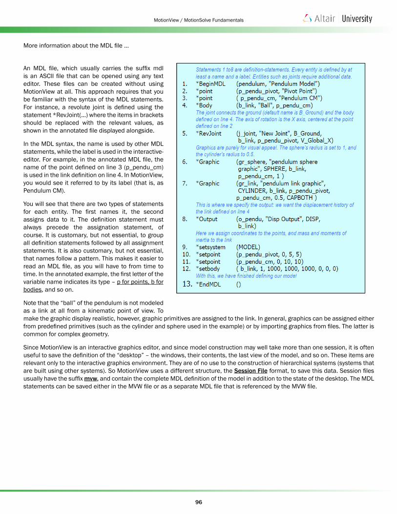
More information about the MDL file ...
An MDL file, which usually carries the suffix mdl is an ASCII file that can be opened using any text editor. These files can be created without using MotionView at all. This approach requires that you be familiar with the syntax of the MDL statements. For instance, a revolute joint is defined using the statement *RevJoint(…) where the items in brackets should be replaced with the relevant values, as shown in the annotated file displayed alongside.
In the MDL syntax, the name is used by other MDL statements, while the label is used in the interactive-editor. For example, in the annotated MDL file, the name of the point defined on line 3 (p_pendu_cm) is used in the link definition on line 4. In MotionView, you would see it referred to by its label (that is, as Pendulum CM).
You will see that there are two types of statements for each entity. The first names it, the second assigns data to it. The definition statement must always precede the assignation statement, of course. It is customary, but not essential, to group all definition statements followed by all assignment statements. It is also customary, but not essential, that names follow a pattern. This makes it easier to read an MDL file, as you will have to from time to time. In the annotated example, the first letter of the variable name indicates its type – p for points, b for bodies, and so on.
Note that the “ball” of the pendulum is not modeled as a link at all from a kinematic point of view. To make the graphic display realistic, however, graphic primitives are assigned to the link. In general, graphics can be assigned either from predefined primitives (such as the cylinder and sphere used in the example) or by importing graphics from files. The latter is common for complex geometry.
Since MotionView is an interactive graphics editor, and since model construction may well take more than one session, it is often useful to save the definition of the “desktop” – the windows, their contents, the last view of the model, and so on. These items are relevant only to the interactive graphics environment. They are of no use to the construction of hierarchical systems (systems that are built using other systems). So MotionView uses a different structure, the Session File format, to save this data. Session files usually have the suffix mvw, and contain the complete MDL definition of the model in addition to the state of the desktop. The MDL statements can be saved either in the MVW file or as a separate MDL file that is referenced by the MVW file.
97
MotionView / MotionSolve Fundamentals
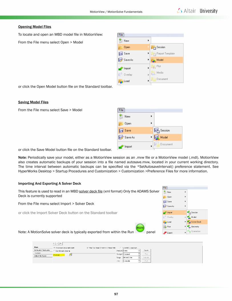
Opening Model Files
To locate and open an MBD model file in MotionView:
From the File menu select Open > Model
or click the Open Model button file on the Standard toolbar.
Saving Model Files
From the File menu select Save > Model
or click the Save Model button file on the Standard toolbar.
Note: Periodically save your model, either as a MotionView session as an .mvw file or a MotionView model (.mdl). MotionView also creates automatic backups of your session into a file named autosave.mvw, located in your current working directory. The time interval between automatic backups can be specified via the *SetAutosaveInterval() preference statement. See HyperWorks Desktop > Startup Procedures and Customization > Customization >Preference Files for more information.
Importing And Exporting A Solver Deck
This feature is used to read in an MBD solver deck file (xml format) Only the ADAMS Solver Deck is currently supported
From the File menu select Import > Solver Deck
or click the Import Solver Deck button on the Standard toolbar
Note: A MotionSolve solver deck is typically exported from within the Run panel

98
MotionView / MotionSolve Fundamentals
5.4.1 Get StartedLaunch MotionView (from Start Menu) and review the baseline model in the Project Browser. The baseline model contains
some items which are created automatically, like the forms for Gravity and Units, the Global reference frame, the Ground Body, and the Global X, Y, and Z vectors, all of which are references which help to build models. [kg mm N s] is the default units set.
5.4.2 Gravity, UnitsWhen a new model is created in MotionView, by default the settings for gravity and units are created for you.
Note: Gravity is set to the negative Z-direction by default.
These can be accessed either via the Model > Misc > Forms or Model > Data Sets folders in the Project Browser:
You only need to choose the settings in one place, and it will be automatically updated in the other section. Both metric and English units are available:
99
MotionView / MotionSolve Fundamentals
5.4.3 Points Points are one of the fundamental construction elements for multi-body models built in MotionView. Almost all the entities that can be created in MotionView need to use points either for defining their location or orientation. Therefore, the creation of points is an important task in model building within MotionView.
Points are design-time entities for MotionView, as opposed to run-time entities for MotionSolve in other words, you will not find points in a MotionSolve model (i.e., input deck), since their only purpose is to help create other entities for MotionSolve (e.g., bodies, joints, forces, etc.)
Note: Points exist only in MotionView, not in MotionSolve files. Points are only used to specify locations for other entities that define MotionSolve models (e.g., markers)
In MotionView you can create three types of points:
1. Single Point
2. Asymmetric Pair Point
3. Symmetric Pair Point
Point Pairs
By default, point pairs are symmetric, and the left side is the master. For symmetric pairs, only the master side can be edited and changes are automatically made to the corresponding side. Click on the Left and Right tabs to switch between the left and right coordinate.
The Symmetric properties check box on the Properties tab allows you to turn symmetry on or off. When symmetry is turned off, both sides can be edited separately. When you turn on symmetry, you are prompted to select a master side.
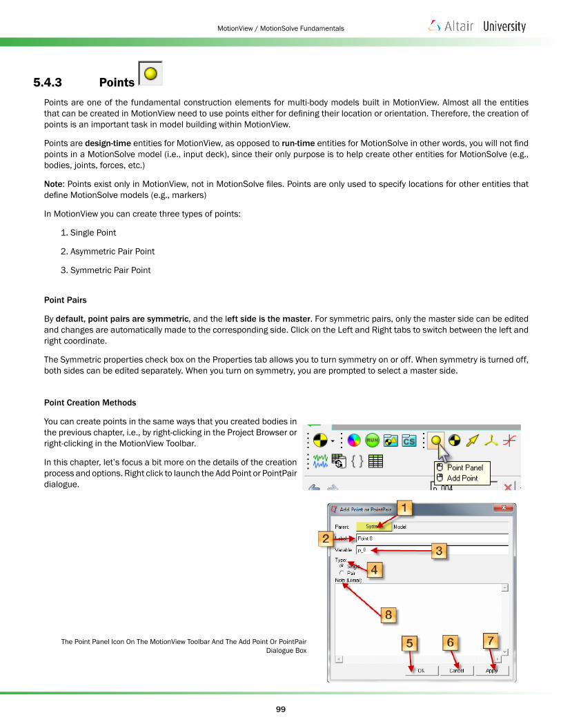
Point Creation Methods
You can create points in the same ways that you created bodies in the previous chapter, i.e., by right-clicking in the Project Browser or right-clicking in the MotionView Toolbar.
In this chapter, let’s focus a bit more on the details of the creation process and options. Right click to launch the Add Point or PointPair dialogue.
The Point Panel Icon On The MotionView Toolbar And The Add Point Or PointPair Dialogue Box
100
MotionView / MotionSolve Fundamentals
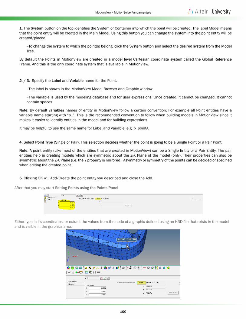
1. The System button on the top identifies the System or Container into which the point will be created. The label Model means that the point entity will be created in the Main Model. Using this button you can change the system into the point entity will be created/placed.
- To change the system to which the point(s) belong, click the System button and select the desired system from the Model Tree.
By default the Points in MotionView are created in a model level Cartesian coordinate system called the Global Reference Frame. And this is the only coordinate system that is available in MotionView.
2. / 3. Specify the Label and Variable name for the Point.
- The label is shown in the MotionView Model Browser and Graphic window.
- The variable is used by the modeling database and for user expressions. Once created, it cannot be changed. It cannot contain spaces.
Note: By default variables names of entity in MotionView follow a certain convention. For example all Point entities have a variable name starting with “p_”. This is the recommended convention to follow when building models in MotionView since it makes it easier to identify entities in the model and for building expressions
It may be helpful to use the same name for Label and Variable, e.g. p_pointA
4. Select Point Type (Single or Pair). This selection decides whether the point is going to be a Single Point or a Pair Point.
Note: A point entity (Like most of the entities that are created in MotionView) can be a Single Entity or a Pair Entity. The pair entities help in creating models which are symmetric about the Z-X Plane of the model (only). Their properties can also be symmetric about the Z-X Plane (i.e. the Y property is mirrored). Asymmetry or symmetry of the points can be decided or specified when editing the created point.
5. Clicking OK will Add/Create the point entity you described and close the Add.
After that you may start Editing Points using the Points Panel
Either type in its coordinates, or extract the values from the node of a graphic defined using an H3D file that exists in the model and is visible in the graphics area.
101
MotionView / MotionSolve Fundamentals
The Measure tab on the Points panel is used to measure the distance between any two points in the model.
• Click on the Measure tab, pick the two points for which the distance is to be calculated and the panel will show the distance between the two points in the highlighted area on the panel.
Besides using the Toolbar, points can also be created in the following ways in MotionView.
• Using the Model Browser (right-click)
• Using MDL statements in an MDL file (via text editor)
• Using macros (TCL scripts)
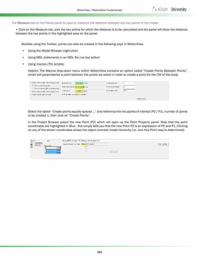
Helpful: The Macros drop-down menu within MotionView contains an option called “Create Points Between Points”, which will parameterize a point between the points we select in order to create a point for the CM of this body.
Select the option “Create points equally spaced ...” and reference the two points of interest (P0 / P1), number of points to be created 1, then click on “Create Points”.
In the Project Browser select the new Point (P2) which will open up the Point Property panel. Note that the point coordinates are highlighted in Blue - this simply tells you that the new Point P2 is an expression of P0 and P1. Clicking on any of the shown coordinates shows the object-oriented model hierarchy (i.e. how this Point was/is determined)
102
MotionView / MotionSolve Fundamentals
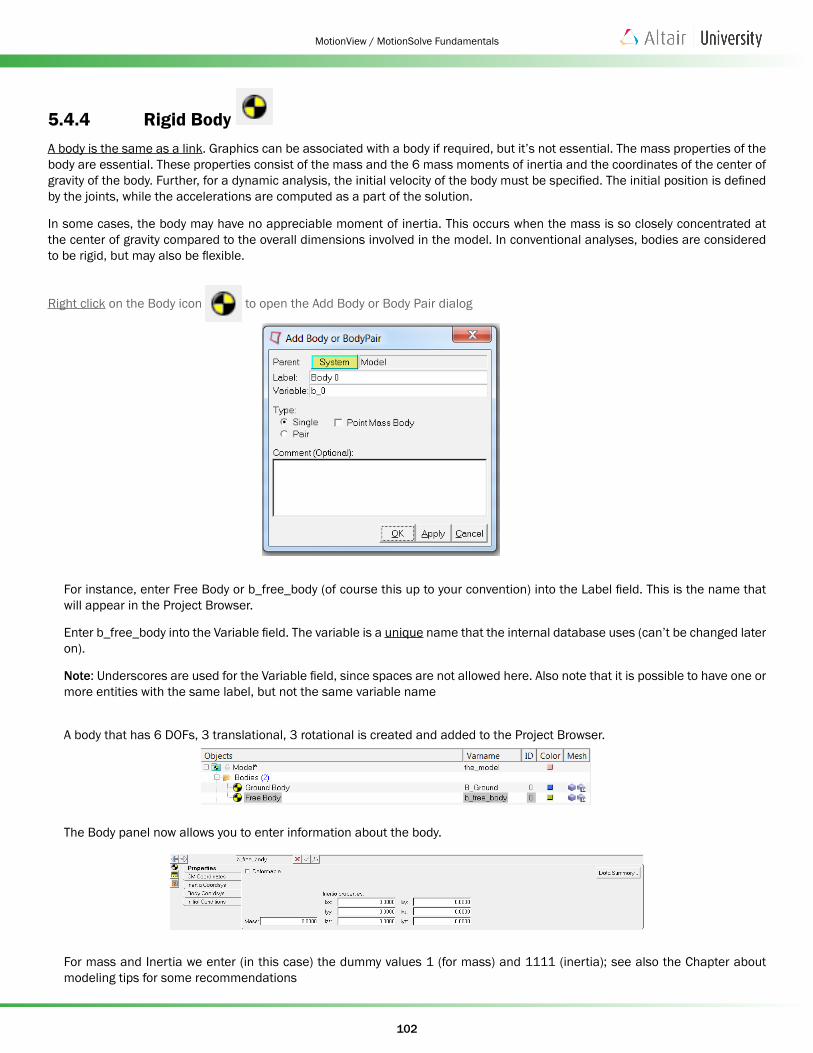
5.4.4 Rigid Body A body is the same as a link. Graphics can be associated with a body if required, but it’s not essential. The mass properties of the body are essential. These properties consist of the mass and the 6 mass moments of inertia and the coordinates of the center of gravity of the body. Further, for a dynamic analysis, the initial velocity of the body must be specified. The initial position is defined by the joints, while the accelerations are computed as a part of the solution.
In some cases, the body may have no appreciable moment of inertia. This occurs when the mass is so closely concentrated at the center of gravity compared to the overall dimensions involved in the model. In conventional analyses, bodies are considered to be rigid, but may also be flexible.
Right click on the Body icon to open the Add Body or Body Pair dialog
For instance, enter Free Body or b_free_body (of course this up to your convention) into the Label field. This is the name that will appear in the Project Browser.
Enter b_free_body into the Variable field. The variable is a unique name that the internal database uses (can’t be changed later on).
Note: Underscores are used for the Variable field, since spaces are not allowed here. Also note that it is possible to have one or more entities with the same label, but not the same variable name
A body that has 6 DOFs, 3 translational, 3 rotational is created and added to the Project Browser.
The Body panel now allows you to enter information about the body.
For mass and Inertia we enter (in this case) the dummy values 1 (for mass) and 1111 (inertia); see also the Chapter about modeling tips for some recommendations
103
MotionView / MotionSolve Fundamentals
Define the Center of Mass (CM coordinate) --> just activate the check box next to “Use center of mass ...”
Define its origin (you need to click on “Origin”), then for instance select from the shown pop-up window (entitled Select a Point) the “Global Origin” (you can review/edit it any time by clicking on “free body” in the Project Browser).
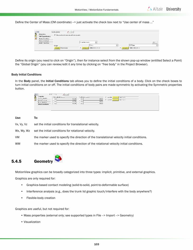
Body Initial Conditions
In the Body panel, the Initial Conditions tab allows you to define the initial conditions of a body. Click on the check boxes to turn initial conditions on or off. The initial conditions of body pairs are made symmetric by activating the Symmetric properties button.
Use: To:
Vx, Vy, Vz set the initial conditions for translational velocity.
Wx, Wy, Wz set the initial conditions for rotational velocity.
VM the marker used to specify the direction of the translational velocity initial conditions.
WM the marker used to specify the direction of the rotational velocity initial conditions.
5.4.5 Geometry
MotionView graphics can be broadly categorized into three types: implicit, primitive, and external graphics.
Graphics are only required for:
• Graphics-based contact modeling (solid-to-solid, point-to-deformable surface)
• Interference analysis (e.g., does the trunk lid graphic touch/interfere with the body anywhere?)
• Flexible-body creation
Graphics are useful, but not required for:
• Mass properties (external only; see supported types in File --> Import --> Geometry)
• Visualization
104
MotionView / MotionSolve Fundamentals
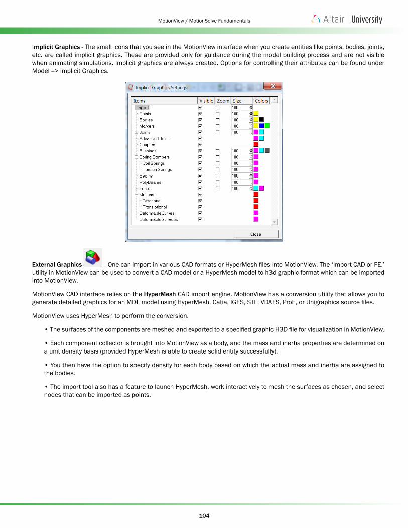
Implicit Graphics - The small icons that you see in the MotionView interface when you create entities like points, bodies, joints, etc. are called implicit graphics. These are provided only for guidance during the model building process and are not visible when animating simulations. Implicit graphics are always created. Options for controlling their attributes can be found under Model --> Implicit Graphics.
External Graphics – One can import in various CAD formats or HyperMesh files into MotionView. The ‘Import CAD or FE.’ utility in MotionView can be used to convert a CAD model or a HyperMesh model to h3d graphic format which can be imported into MotionView.
MotionView CAD interface relies on the HyperMesh CAD import engine. MotionView has a conversion utility that allows you to generate detailed graphics for an MDL model using HyperMesh, Catia, IGES, STL, VDAFS, ProE, or Unigraphics source files.
MotionView uses HyperMesh to perform the conversion.
• The surfaces of the components are meshed and exported to a specified graphic H3D file for visualization in MotionView.
• Each component collector is brought into MotionView as a body, and the mass and inertia properties are determined on a unit density basis (provided HyperMesh is able to create solid entity successfully).
• You then have the option to specify density for each body based on which the actual mass and inertia are assigned to the bodies.
• The import tool also has a feature to launch HyperMesh, work interactively to mesh the surfaces as chosen, and select nodes that can be imported as points.
105
MotionView / MotionSolve Fundamentals
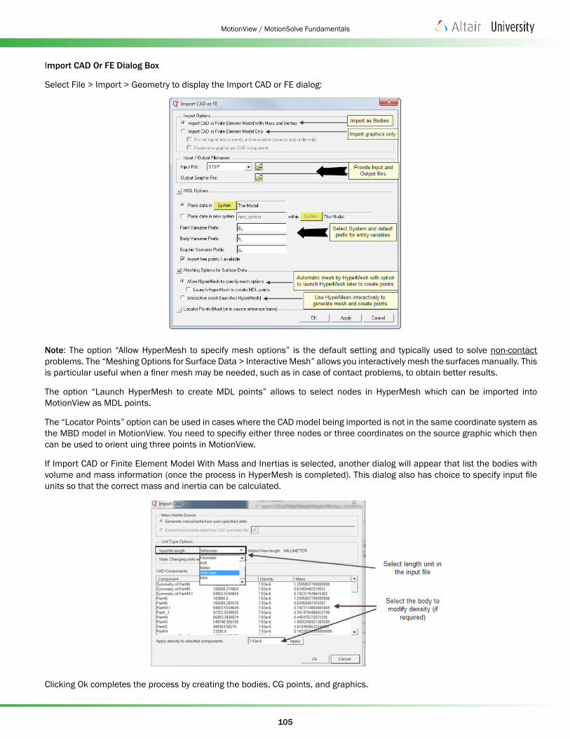
Import CAD Or FE Dialog Box
Select File > Import > Geometry to display the Import CAD or FE dialog:
Note: The option “Allow HyperMesh to specify mesh options” is the default setting and typically used to solve non-contact problems. The “Meshing Options for Surface Data > Interactive Mesh” allows you interactively mesh the surfaces manually. This is particular useful when a finer mesh may be needed, such as in case of contact problems, to obtain better results.
The option “Launch HyperMesh to create MDL points” allows to select nodes in HyperMesh which can be imported into MotionView as MDL points.
The “Locator Points” option can be used in cases where the CAD model being imported is not in the same coordinate system as the MBD model in MotionView. You need to specifiy either three nodes or three coordinates on the source graphic which then can be used to orient uing three points in MotionView.
If Import CAD or Finite Element Model With Mass and Inertias is selected, another dialog will appear that list the bodies with volume and mass information (once the process in HyperMesh is completed). This dialog also has choice to specify input file units so that the correct mass and inertia can be calculated.
Clicking Ok completes the process by creating the bodies, CG points, and graphics.
106
MotionView / MotionSolve Fundamentals
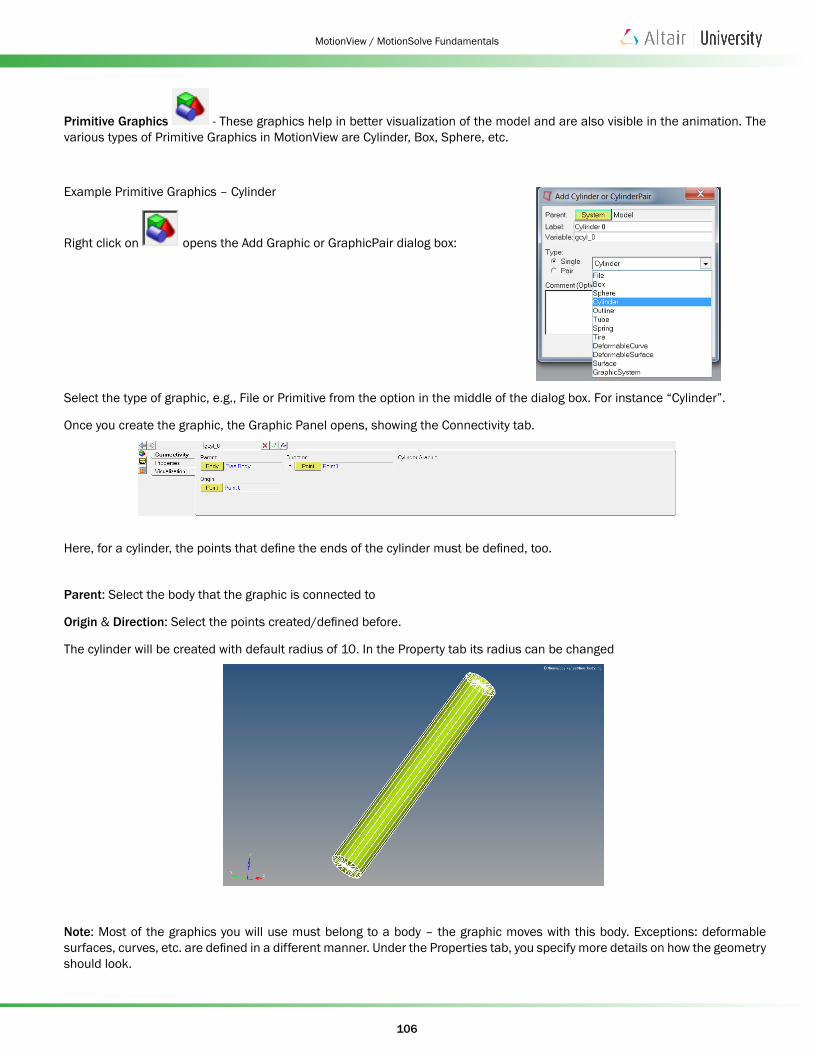
Primitive Graphics - These graphics help in better visualization of the model and are also visible in the animation. The various types of Primitive Graphics in MotionView are Cylinder, Box, Sphere, etc.
Example Primitive Graphics – Cylinder
Right click on opens the Add Graphic or GraphicPair dialog box:
Select the type of graphic, e.g., File or Primitive from the option in the middle of the dialog box. For instance “Cylinder”.
Once you create the graphic, the Graphic Panel opens, showing the Connectivity tab.
Here, for a cylinder, the points that define the ends of the cylinder must be defined, too.
Parent: Select the body that the graphic is connected to
Origin & Direction: Select the points created/defined before.
The cylinder will be created with default radius of 10. In the Property tab its radius can be changed
Note: Most of the graphics you will use must belong to a body – the graphic moves with this body. Exceptions: deformable surfaces, curves, etc. are defined in a different manner. Under the Properties tab, you specify more details on how the geometry should look.