5 h.p. chipper-shredder - sears parts directb. with chipper-shredder level, fill engine with oil to...
TRANSCRIPT

OWNERSMANUAL
MODEL NO.247.796890
_ WARNING
Carefully read andfollow SafetyRules, Precautionsand OperatingInstructions, Failureto do so can result
in serious personalinjury.
5 H.P.CHIPPER-SHREDDER
It
tl
Assembly • MaintenanceOperation , Repair PartsAlways wear eye protection duringoperation
i i ,,,,,,,,,
Sold by Sears, Roebuck and Co, Chicago ilt 60684 USA
Part No. 770-5875B 8/87

REAR
Eel
Ramp
Muffler
Cleaner
Control
Tank
lopper
Chip-It ChuteDeflector
Spark Plug.and Elbow
CatcherStarter Bag
ModelPlate FRONT
INDEX
MODELNUMBER
SERIALNUMBER
THE MODEL AND SERIAL NUMBERSWILL BE FOUND ON THE MODEL PLATEATTACHED TO THE FRAME SEE ILLUSTRA-TION AT LEFT
YOU SHOULD RECORD BOTH MODEL ANDSERIAL NUMBERS AND KEEP IN A SAFEPLACE FOR FUTURE REFERENCE,
i& Instructions given with this sym-bol are for personal safety° Besure to follow them. l
Warranty ......Rules for Safe OperationAssemblyOperationHow to Use Your Chipper-Shredder
Adjustments
23
_ 4
67
9
Maintenance ....... 9
Off-Season Storage ........ 11Maintenance Check List .... 12
Trouble Shooting Chart 12Repair Parts ...... 13-19
MAINTENANCE AGREEMENT
A Sears Maintenance Agreement is available on this product Contact your nearest Sears store for details°
LIMITED ONE YEAR WARRANTY ON CRAFTSMAN GAS CHIPPER-SHREDDER
For one year from the date of purchase, when this Craftsman Chipper-Shredder is maintained, lubricatedand tuned up according to the instructions in the owner's manual, Sears will repair, free of charge, any defectin material and workmanship.
tf this Craftsman Chipper-Shredder is used for commercia_ or rental purpose, this warranty applies for only
30 days from the date of purchase
This warranty does not cover:
-- Expendable items which become worn during normal use, such as blades, blade guides, blade adapters,air cleaners, spark plugs and catcher bags;
-- Repairs necessary because of operator abuse or negligence, including bent crankshafts
WARRANTY SERVICE IS AVAILABLE BY RETURNING THE CRAFTSMAN CHIPPER-SHREDDER TO THENEAREST SERVICE CENTER/DEPARTMENT IN THE UNITED STATES
This warranty gives you specific legal rights, and you may also have other rights which vary from state to state
SEARS, ROEBUCK AND CO, Dept 698t731A, Sears Tower, Chicago, IL 60684
NOTE
This unit is equipped with an internat combustion engine and should no[ be used on or near any unimproved forest-covered, brush-covered or grass-covered land unless the engine's exhaust system is equipped with a spark attestermeeting applicable tocaf or state laws (if any) If a spark attester is used, it should be maintained in effective work-ing order by the operator
In the State of California the above is required by law (Section 4442 of lhe California Public Resources Code) Other
states may have similar laws Federal law apply on federaf lands A spa_k arrester muffler is available at your SearsAuthorized Service Center (see page 19)
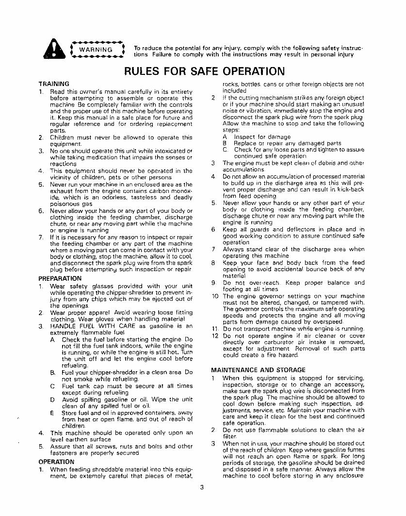
WARNING Toreducethe potential for any injury, comply with the following safety instruc-- - _ tions Failure to comply with the instructions may result in personal injury
RULES FOR SAFE OPERATIONTRAINING
1 Read this owner's manual carefully in its entiretybefore attempting to assemble or operate thismachine Be completely familiar with the controlsand the proper use of this machine before operatingit, Keep this manual in a safe place for future andregular reference and for ordering replacementparts,
2. Children must never be allowed to operate thisequipment_
3., No one should operate this unit while intoxicated orwhile taking medication that impairs the senses orreactions
4, This equipment should never be operated in thevicinity of children, pets or other persons
5. Never run your machine in an enclosed area as theexhaust from the engine contains carbon monox-ide, which is an odorless, tasteless and deadlypoisonous gas
6,, Never allow your hands or any part of your body orclothing inside the feeding chamber, dischargechute, or near any moving part while the machineor engine is running
7, If it is necessary for any reason to inspect or repairthe feeding chamber or any part of the machinewhere a moving part can come in contact with yourbody or clothing, stop the machine, allow it to cool,and disconnect the spark plug wire from the sparkplug before attempting such inspection or repair
PREPARAT'ION
t, Wear safety glasses provided with your unitwhile operating the chipper-shredder to prevent in-jury from any chips which may be ejected out ofthe openings
2. Wear proper apparel Avoid wearing loose fittingclothing, Wear gloves when handling material
3 HANDLE FUEL WITH CARE as gasoline is anextremely flammable fuelA Check the fuel before starting the engine, Do
not fill the fuel tank indoors, while the engineis running, or while the engine is still hot,, Turnthe unit off and let the engine coot beforerefueling,
B, Fuel your chipper-shredder in a clean area Donot smoke while refueling,
C Fuel tank cap must be secure at all timesexcept during refueling
D Avoid spilling gasoline or oil. Wipe the unitclean of any spilled fuel or oil,
E Store fuel and ell in approved containers, awayfrom heat or open flame, and out of reach ofchildren,
4_ This machine should be operated only upon anlevel earthen surface
5, Assure that aft screws, nuts and bolts and otherfasteners are properly secured
OPERATION
1, When feeding shreddable materiat into this equip*ment, be extemely careful that pieces of metal,
rocks, bottles, cans or other foreign objects are notincluded
2 If the cutting mechanism strikes any foreign objector if your machine should start making an unusualnoise or vibration, immediately stop the engine anddisconnect the spark piug wire from the spark plugAllow the machine to stop and take the followingsteps:A Inspect for damageB Replace or repair any damaged partsC Check for any loose parts and tighten to assure
continued safe operation3 The engine must be kept clean of debris and other
accumulations_
4 Do not allow an accumufation of processed materialto build up in the discharge area as this will pre-vent proper discharge and can result in kick-backfrom feed opening
5 Never allow your hands or any other part of yourbody or clothing inside the feeding chamber,discharge chute or near any moving part while theengine is running
6 Keep ell guards and deflectors in place and ingood working condition to assure continued safeoperation
7 Always stand clear of the discharge area whenoperating this machine
8 Keep your face and body back from the feedopening to avoid accidental bounce back of anymateriel
9 Do not over.reach Keep proper balance andfooting at all times
10 The engine governor settings on your machinemust not be altered, changed, or tampered with,The governor controls the maximum safe operatingspeeds and protects the engine and all movingparts from damage caused by overspeed,
11 Do not transport machine while engine is running
12 Do not operate engine if air cleaner or coverdirectly over carburetor air intake is removed,except for adjustment Removal of such partscould create a fire hazard.
MAINTENANCE AND STORAGE
1 When this equipment is stopped for servicing,inspection, storage or to change an accessory,make sure the spark plug wire is disconnected fromthe spark plug The machine should be allowed tocool down before making such inspection, ad_justments, service, etc Maintain your machine withcare and keep it clean for the best and continuedsafe operation,
2 Do not use flammable solutions to clean the airfitte_
3 When not in use, your machine should be stored outof the reach of children Keep where gasoline fumeswill not reach an open flame or spark, For longperiods of storage, the gasoline should be drainedand disposed in a safe manner, Always allow themachine to cool before storing in any enclosure
3

NOTE
This unit is shipped WITHOUT GASOLINEor OIL, After assembly, see operationsection of this manual for proper fuel andengine oll recommendations
ASSEMBLY INSTRUCTIONSTools Required for Assembly:
121 7/16" Open End or Box Wrenches"(1) 1/2" Socket Wrench
* An Adiustable Wrench may be used in place of oneof the wrenches
NOTE
The right and left side of your chipper-shredder is determined from behind theunit,
o--@@FIGURE 1,
UNPACKING
Remove the chipper-shredder and loose parts from thecarton,, Make certain all parts and literature have beenremoved before the carton is discarded,
Parts in Carton:
Chipper-ShredderChute DeflectorHopperUpper Leaf Ramp Section
Catcher BagHardware Pack
Safety Glasses
Contents of Hardware Pack (See Figure 1):
A (8) Hex Bolts 1/4-20 x 1/2" LongB (8) Hex Lock Nuts 1/4-20 ThreadC t6) Hex Washer Head Self-Tapping Screws
5/16-18 x 3/4" LongD (2) Keepers
Hex Bolts (A)Hex Lock
..,_.Nutsj-
ChuteDeflector
CHUTE DEFLECTOR INSTALLATION
1, Place the chute deflector in position on the
discharge opening (on the left side of the chipper-shredder) See figure 2
2 Secure chute deflector to discharge opening withhex bolts (A) and hex lock nuts IB) Heads of thehex bolts are inside the discharge opening Hex nuts
go on the outside
3 Tighten all four nuts and bolts securely
FIGURE 2.
No
Self-TappingScrews (C)
Lower LeafRamp Section
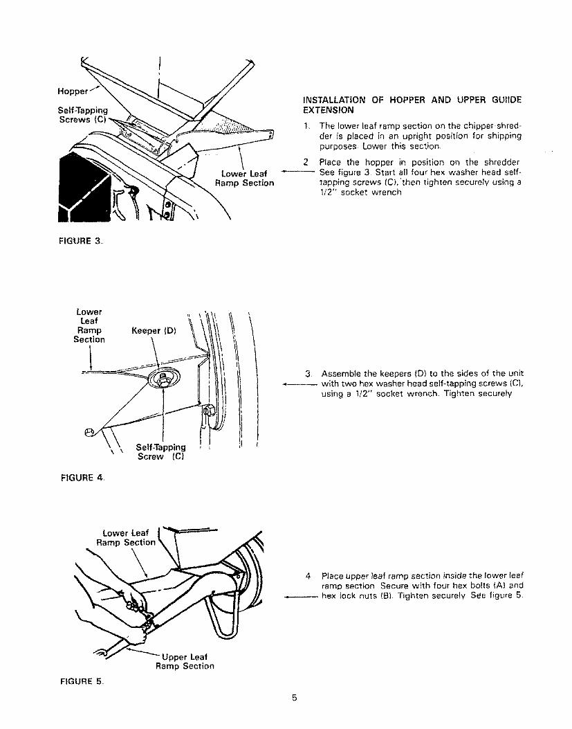
INSTALLATION OF HOPPER AND UPPER GUItDEEXTENSION
1. The lower leaf ramp section on the chipper-shred-der is placed in an upright position for shippingpurposes Lower this section,
2, Place the hopper in position on the shredder-- m See figure 3. Start all four hex washer head self-
tapping screws/C),'then tighten securely using a1/2" socket wrench
FIGURE 3.
Lowe rLeaf
RampSection
Keeper(D)
3 Assembte the keepers (D) to the sides of the unit•-------- with two hex washer head self-tapping screws (C),
using a t/2" socket wrench, T_ghten securely
\ _ Self-TappingScrew (C)
FIGURE 4.
Lower Leaf __Ramp Section _ \
Ramp Section
FIGURE 5.
4 Place upper leaf ramp section inside the lower fearramp section Secure with four hex bolts (A) andhex lock nuts (B). Tighten securely See figure 5

ATTACHING THE CATCHER BAG
Your unit is equipped with a nylon bag which attachesto the discharge opening. If desired, place the end ofthe bag over the chute deflector. Depress plunger, pullon the drawstring, and reIease plunger to lock it inposition. See figure 6
FIGURE 6.
oPERATIONGAS AND OIL FILL tJP
....................... :. ............................. ii lUHl=
2 Fill fuel tank. See figure 8. Use fresh, clean,unleaded automotive gasoline. Capacity is 3 quarts_
NOTE
ENGINE lS SHIPPED WITHOUT OIL. FILLCRANKCASE WITH OIL BEFORE STAR-TtNG BE VERY CAREFUL NOT TOALLOW DIRT TO ENTER THE ENGINEWHEN CHECKING OR ADDING OIL ORFUEL
Recommended SAE Viscosity Grades
LIII TI !o! o T9ErrI, ,,,!! r !t!r
-20 ° 0 o 32 ° 60 ° 80 ° 100 °
TEMPERATURE RANGE EXPECTED BEFORE NEXT OILCHANGE, ALL OILS MUST A,PI SERVICE CLASSIFICA-TION SD, SE OR SE
1, Fill engine with oil,a Remove engine oil fillplug. See figure 7.b. With chipper-shredder level, fill engine with oil
to point of overflowing. Capacity is 1-1/4 pintsc Tilt chipper-shredder forward on its wheels,
then re-level.d Check oil level, Refill to point of over-flowing
if necessary. Replace oil fill plug.
j o_ \'tll))i
Plug
tOilDrain Plug
FIGURE 7.
FuelTank
FIGURE 8,
Throttle
Control Lever luffler
• parkPlug,
and
t w...,.otFill to within 1/2 inch of top of fuel tank
to prevent spills and to allow for fuelexpansion If gasoline is accidently spill-ed, move chipper-shredder away fromarea of spill Avoid creating any source ofignition until gasoline vapors havedisappeared,
NOTE
DO NOT USE GASOHOL OR
METHANOL. These type fuels react withwater content in the fuel and tend to form
strong acids which can corrode metalparts and harm rubber plastics_
USE CLEAN OIL AND FUEL. STORE INAPPROVED, CLEANI COVERED CON+TAINERS, USE CLEAN FILL FUNNELS.
6
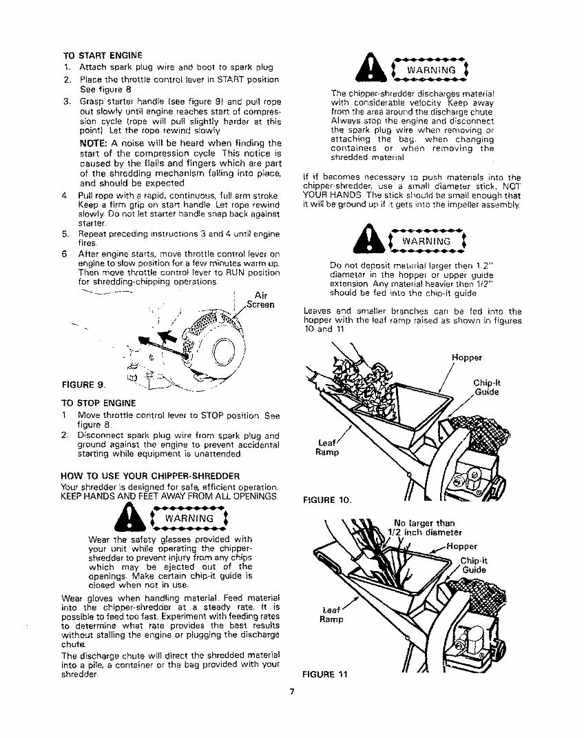
FIGURE 9.
TO START ENGINE
1, Attach spark ptug wire and boot to spark plug
2. Place the throttle control lever in START positionSee figure 8
3. Grasp starter handfe (see figure 9) and pull ropeout slowly until engine reaches start of compres-sion cycle (rope will pull slightly harder at thispoint). Let the rope rewind slowly
NOTE: A noise will be heard when finding thestart of the compression cycle This notice is
caused by the flails and fingers which are partof the shredding mechanism falling into ptace,and should be expected,
4 Pull rope with a rapid, continuous, full arm strokeKeep a firm grip on start handle Let rope rewindslowly. Do not let starter handle snap back againststarter,
5, Repeat preceding instructions 3 and 4 until enginefires,
6, After engine starts, move throttle control lever onengine to slow position for a few minutes warm up,Then move throttle control lever to RUN positionfor shredding-chipping operations
""-" ......... _ Air- i .Screen
TO STOP ENGINE
1 Move throttle control lever to STOP position Seefigure 8
2, Disconnect spark plug wire from spark p_ug andground against the engine to prevent accidentalstarting while equipment is unattended
HOW TO USE YOUR CHIPPER-SHREDDERYour shredder is designed for safe, efficient operation.KEEP HANDS AND FEETAWAY FROM ALL OPENINGS
WARNING
Wear the safety glasses provided withyour unit while operating the chipper-shredder to prevent injury from any chipswhich may be ejected out of theopenings, Make certain chip-it guide isclosed when not in use,
Wear gloves when handling material Feed materialinto the chipper-shredder at a steady rate It ispossible to feed too fast° Experiment with feeding ratesto determine what rate provides the best resultswithout stalling the engine or plugging the dischargechute.
The discharge chute will direct the shredded materialinto a pile, a container or the bag provided with yourshredder
i wARN, GIThe chipper-shredder discharges materialwith considerable velocity Keep awayfrom the area around the discharge chuteAlways stop the engine and d_sconnectthe spark plug wire when removing orattaching the bag when changingcontainers or when removing theshredded material
if if becomes necessary to push materials into thechipper-shredder, use a small diameter stick, NOTYOUR HANDS The stick sl_ould be small enough thatit will be ground up if it gets into the impeller assembly.
Do not deposit material larger then 12"diameter in the hoppe_ or upper guideextension Any material heavier then 1/2"should be fed _nto the chip-it guide
Leaves and smaller branches can be fed into thehopper with the leaf ramp raised as shown in figures10 and 11
Hopper
Chip-itGuide
FIGURE 10.
No larger than112 inch diameter
)or
Chip-it
LeafRamp
FIGURE 11

Lower the leaf ramp by holding the handle and pulling
up on the release bar See figure 12 Leaves and smalltwigs can be raked into the chipper-shredder with theleaf ramp in this position See figure 13
Handle
Leaf Ramp
No larger than1t2 inch diameter
FIGURE 14.
Elastic> Lock
Nuts
\
FIGURE 12.
Bulky material, such as stalks or heavy
branches (anything over tt2" diameter),should be fed into the chip-it guide.. See
figure 15. Do not force or jam material in-to the chip-it guide Make certain leaframp is raised as shown in figure 15 whenusing the chip-it guide
Make certain chip-it guide door is closedwhen not in use
FIGURE 13o
Leaf Ramp ,_(
Small branches can also be fed into the leaf ramp See
figure 14
Keep Leaf Ramp RaisedWhen Using Chip-It Guide
FIGURE 15,

ADJUSTMENTS
CARBURETOR ADJUSTMENT
If any adjustments are made to the enginewhile the engine if running {eg. car-buretor), keep clear of all moving partsBe careful of heated surfaces and muffler
Minor carburetor adjustment may be required to com-
pensate for differences in fuel, temperature, altitude ortoad
NOTE
Test the engine by operating the chipper-shredder.If engine tends to stall or die out, it dsuallyindicates that the mixture is slightly lean and it maybe necessary to open ,f',) the needle valve slightlyto provide a richer mixture This richermixture may cause a slight unevenness in idling.
L
FIGURE 16.
Idle Speed
Adjusting Screw
Needle Valve
Throttle
Stop
i
Throttle
A DIRTY AIR CLEANER WILL CAUSEENGINE TO RUN ROUGH BE CERTAINAIR CLEANER IS CLEAN AND ATTACH-
ED TO THE CARBURETOR BEFOREADJUSTING CARBURETOR DO NOTMAKE UNNECESSARY ADJUSTMENTS
FACTORY SETTINGS ARE SATISFAC-TORY FOR MOST APPLICATIONS ANDCONDITIONS.
Never attempt to change maximum engine speed It ispre-set at the factory and should be changed only bya qualified service technician who has the necessaryequipment,
The carburetor may need re-adjusting if engine lackspower or does not idle properly if adjustments areneeded, proceed as follows.To Adjust Carburetor:
1. Close needle valve (See figure 16) clockwise
(("_ } finger tight only Forcing may cause damage_Then open 1-!/2 turns counterclockwise (r'x)
2. Start engine and allow to warm for five minutes.
3 With throttle in RUN position, close needle valveclockwise (;-_,) until engine starts to lose speed(lean mixture). Then slowly open needle valvecounterclockwise (f'_) until engine JUST BEGINSto run unevenly This mixture should be rich enoughfor best performance under load.
Place throttle control in IDLE position:
a_ If engine idtes, no further adjustment isnecessary.
b tf engine idles too fast, turn idle speedadiusting screw counterclockwise _(-",) untilslower speed is obtained
c If engine dies, turn idle speed adjusting screw1f4 turn clockwise ((-'_) Place throttlecontrol in FAST position and restart engine
d Move throttle control to IDLE position Ifengine does not idle, repeat step c
MAINTENANCE
Disconnect spark plug wire and ground
it against the engine before performingany repairs or maintenance.
ENGINE LUBRICATION
Your four cycie engine will normally consume some oil;therefore check engine oil level regularly - approximately,every five hours of operation and before each usageStop engine and wait several minutes before checkingoil level. With engine level, the oil must be even withthe oil fill (refer to figure 7) Change engine oil after thefirst two hours of operation, and every twenty, fivehours thereafter
I_ Drain oil while engine is warm
a. Remove oil drain plug Refer to figure 7
b. Tip the chipper-shredder forward, and catch oilin a suitable container
c. When engine is drained of all oil, replace drainplug securely.
2 Refif] with fresh oi! Above 32 °, use oil labeledSAE 3OW or !0W30 Below 32 °, use oil labeled
5W20 Capacity is 1-1i4 pints Refer to "Gas andOil FilFUp" on page 6
3. Replace oil fill plug

AIR CLEANER
The air cleaner prevents damaging dirt, dust, etc, fromentering the carburetor and being forced into the engineand is important to engine life and performance
Never run your engine without air cleaner completelyassembled-
To Service Air Cleaner:
Clean and re-oil foam pro-cleaner at three monthintervals or every 25 hours, whichever occurs first:See figure I7 Service more often under dustyconditions
1, Remove knob and coven
2, Remove foam pre-cleaner by sliding it off thepaper cartridge.ao Wash foam pre-cleaner in liquid detergent
and water_
b Wrap foam pre-cleaner in cloth and squeezedry.
c Saturate foam pre-cleaner in clean engineoil, Sqeeze to remove excess oil
3. Install faom pre-cleaner over paper cartridge°Reassemble cover and screw down tight,
Replace and clean cartridge included with dualelement air cleaner yearly or every 100 hours,Service more often if necessary.
Clean cartridge by tapping gently on a flat surfaceIf very dirty, replace cartridge or clean as fotlows:
a Wash in a tow or non-sudsing detergent andwarm water solution CAUTION: Do not usepetroleum solvents such as kerosene, to cleancartridge
b. Rinse thoroughly with flowing water frominside out until water is clear.
4_
c AHow cartridge to stand and air dry thoroughlybefore using DO NOT OIL CARTRIDGE, DONOT USE PRESSURIZED AIR TO CLEAN ORDRY CARTRIDGE
Install cartridge and pre-cleaner then the cover,
Screw knob down securely,
(_Tj-._----_ Knob
" ._' Cover
j
. i,(_"¢<1&_£._¢___,._--Cart ridge
MUFFLER
Do not operate the chipper-shredder without a muffleror tamper with the exhaust system Damaged mufflersor spark attesters could create a fire hazard inspectperiodicalty, and replace if necessary, If your engine isequipped with a spark arrester screen assembly, removeevery 50 hours for cleaning and inspection Replace ifdamaged
CLEAN ENGINE
Clean engine perlodicailyl Remove dirt and debris with
a cloth or brush Cleaning with a forceful spray of wateris not recommended as water could contaminate the
fuel system,
Yearly or every 50 hours, whichever occurs first, removethe blower housing and clean the areas shown in figure18 to avoid overspeeding, overheating and enginedamage Clean more often if necessary,
Periodically clean muffler area to removeall grass, dirt and combustible debris,
FIGURE 18
Clean OutChaff and
Dirt
SPARK PLUG
The spark plug should be cleaned and the gap resetto 030" at least once a season or every 50 hours ofoperation Spark plug replacement is recommended atthe start of each season, Refer to engine parts list forcorrect spark plug type
NOTE: Do not blast clean spark plug Spark plug shouldbe cleaned by scraping or wire brushing and washingwith a commercial solvent
,030 Feeler Guage
Spark Plug
FIGURE !7_ FIGURE !9,
10

LUBRICATION
Wheels - The wheels require no lubrication,
Flails and Fingers - If the unit is disassembled for anyreason, lubricate the flails and fingers with a light oil(engine oil may be usedtCUTTING BLADE
The cutting blade may be removed for grinding orreplacement as follows
1 Lower the upper guide extension
2, Block up the housing See figure 20.3. Remove the four elastic lock nuts from the back
of the housing using a 1/2" wrench Refer to figure14. Separate the shredder into two halves
4, Remove the back-up ptater See figure 20
NOTE
When reassembling, make certain theopening on the back up plate is towardthe bottom of the unit The back up platemay be reversed to provide a new cuttingedge
, , WeEd B ,
x.,
Blade
Blade
/Back-Up /
Plate_. ,__ .....
FIGURE 20,
5. Hold the blade retainer on the impeller assemblywith an adjustable wrench to keep the blade fromturning as shown in figure 20
6, Remove the blade by removing the center bolt, lockwasher and fiat washer
NOTE
Use caution when removing the blade toavoid contacting the weld boltsprotruding from the housing.
WARNINGThe blade is reversible and can beassembled to the crankshaft with eitherside showing
When sharpening the blade, follow the original angleof grind as a guide. It is extremely important that eachcutting edge receives an equal amount of grinding toprevent an unbalanced blade An unbalanced blade wil!cause excessive vibration when rotating at high speedsand may cause damage to the unit
The blade can be tested by balancing it on a round shaftscrewdriver or nail Remove metal from the heavy sideuntil it balanced evenly See figure 21
Nai, / \
°,o0e C7FIGURE 21
When reassembling the blade, tighten to between 375and 450 inch pounds, or lacking torque wrench, tightensecuret¥FLAILS AND FINGERS
The flails and fingers may be _eversed when theybecome dull It is suggested that this procedure beperformed by your nearest Sears Service Department
OFF-SEASON STORAGEtf the chipper-shredder is to be inoperative for a periodlonger than 30 days, the following precautions arerecommended.
I Working outdoors, drain all [uel from the fue! tank.Run the engine until it stops from lack of fuel
DO NOT DRAIN FUEL WHILE SMOKING,OR IF NEAR AN OPEN FIRE
2, Drain alI the oil from the crankcase (this should bedone after the engine has been operated and is stillwarm) and refill crankcase with fresh oi!
3 Protect the inside of the engine for storage asfollows
Remove spark plug, pour approximately !/2 ounce(approximately one tablespoonl of engine oil intocylinder and crank slowly to distribute oil Replacespark plug
4 Clean the engine and the entire chipper-shredderthoroughly
NOTE
When storing any type of powerequipment in an unventilated or metalstorage shed. care should be taken torustproof the equipment. Using a tight oilor silicone, coat the equipment, especiallyall moving parts
Store in a clean, d_y area
1!
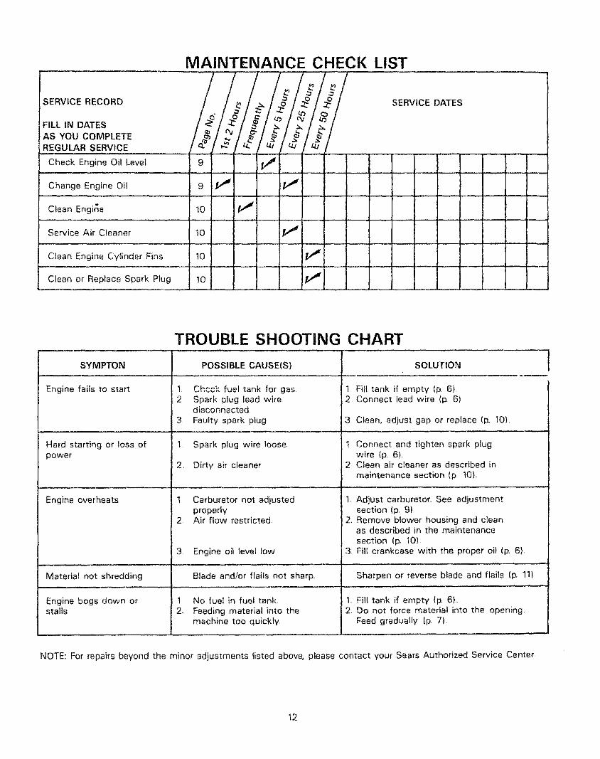
MAINTENANCE CHECK LIST
SERVICE RECORD
FILL tN DATES
AS YOU COMPLETE
REGULAR SERVICE
Check Engine Oil Level
Change Engine Oil
SERVICE DATES
Clean Engine
Service Air Cleaner, , ..... ,,,
Clean Engine Cylinder Fins
Clean or Repface Spark Plug
9 V"
SYMPTON
Engine fails to start
Hard starting or loss ofpower
Engine overheats
TROUBLE SHOOTING CHART
2
3
2,
POSSIBLE CAUSE(S)
Check fuel tank for gas,Spark plug lead wiredisconnected
Faulty spark ptug
Spark plug wire loose,
Dirty air cleaner
1 Carburetor not adjustedproperly
2 Air flow restricted.
SOLUTION
] Fill tank if empty ip. 6)2 Connect lead wire (p, 6)
3 Ciean, adjust gap or replace (p, 10)
1. Connect and tighten spark plugwire (p 6)
2 Clean air cleaner as described in
maintenance section (p !0),
2.
Adjust carburetor, See adjustmentsection (p, 91Remove blower housing and cleanas described in the maintenancesection (p_ 10)Fill crankcase with the proper oil (p. 6),3 Engine oil level tow 3,
Material not shredding Blade andlor flails not sharp Sharpen or reverse blade and flails (13.11)
Engine bogs down or t No fuel in fuel tank 1, Fill tank if empty (13.6),stalls 2. Feeding material into the 2. Do not force material into the opening
machine too quickly, Feed gradually (p. 7)
1
NOTE: For repairs beyond the minor adjustments listed above, please contact your Sears Authorized Service Center
12

Repair Parts 5 H.P. Chipper-Shredder--Model 247.796890
3 4 51 2
9
42 13 14 /75?
18
/
38
34
24
\25 20
43
\53 52
13

Repair Parts5,H°P. Chipper-Shredder--Model 247_796890
KeyNon Part Noo Description
123456789
11476710-0465711-0580711-057911455736-0921726-0111712-0922714-0507
10 1656811 712-010712 710-028913 714-Ol1414 1343015 710-0157t6 736-0119t7 1457318 5 HR19 11464
20 712-01232t 736-011922 738-052123 736-017024 726-022125 711-049426 734-117327 736-010028 710-062429 712-042930 710-0237
Door Chip It
Hex Bolt I12o20 x 4 50" Lg,*Clevis Pin
Flail Spacer W32" LgCutting FingerL-Wash 1/2" I,D.*Patnut 3/16" Dia,Hex Jam Nut 1!2-20 Thd*Cotter Pin 3/32" Dia x 3/4"
Lg*Chute DeflectorL.-Nut t/4-20 Thd
Hex Bolt 114-20 x 50" Lg.*Sq Key ti4" x 2( Lg,Impeller AssemblyHex Bolt 5116-24 3/4" Lg,"L-Wash_ 5t16"' ID,'Hopper to Engine Mtg, PlateEngine - B & S 13 :12-1731-01
Engine Mounting ateHex Nut 5/16-24 "hd*L,-Wash 5t16" I.DShaft
Special L-Wash 5'16" IDPush CapSpacerWheel Ass'y-Com!Fl,-Wash 50" t,D,Hex Bolt 5/16-24 1 50" Lg,*Elastic Lock Nut 5t16-18 Thd
Hex Bolt 5116-24 62" Lg,*
.'evINo_ I
31 I
32 1
33 I34 I35 136 I
37 I38 139 I4O I
41 I42 t43 I44 I45 I46 t47 148 l49 I50 I
52 {53 155 f56 [57 I
Part No. Description
7t4-0144
736-0192
11459711-0564711-0578736-0247
736-O2t7710-O'15114575--629732-0546
1147711478747-O53t712-0109]343111460--62916524--629736-026411481--629710-0601
114541652211480710-0542735-0639764-0199723-0400
Cotter Pin 1/8" Dia x 100"
Lg" (Specia0Ft-Wash ,531" ID x 937
OD x .09Ftai]
Flail Spacer 23132" LgClevis Pin 50" Dia, x 30" LgF1,-Wash, 406" ID, x 125"
O-D, Hdn,L,-Wash 3/8" ID HD,
Hex Bolt 318-24 x 20" Lg HTFlail Housing Ass'y.-CompTorsion Spring 062 Dia x 106
Lg.Chip-It Guide Ass°v.Hinge PinRelease Bar
Wing Nut Elastic 1/4-20 ThdBlade
Upper Leaf Ramp SectionLower Leaf Ramp SectionFL-Washo 5t16" LDHopper AssemblyHex Wash,. Hd, Self-Tap Scr
5/16-18 x 75" LgBack-Up PlateInlet Guide AssemblyStop WasherHex Bolt 5/16-t8 x 8,38" LgSpark Plug ElbowBag (Not Shown)
Safety Glasses (Not Shown)
*Common Hardware - May be purchased locally.
NOTE: Specifications subject to change without notice or obligation,
!4

Repair Parts5 H.P, ChipperShredder--Model 247.796890
Engine--Model 130212 Type 1731-01
26
541
( )P
30
615@6'
230
383
741
16
21946 @
220
_'25
36
208 201
35
529
_IICSPE¢IALIOOLS REQUIREDTO INSTALL
SEEREPAIRINSTRUCTION15 MANUAL
[358 GASKET SET I
298
0
299
!5

Repair Parts5' H.R Chipper-Shredder--Mode! 247.796890
Engine--Model 130212 Type 1731-01
*BEouInEsSPECIAL TOOLS
Zo_ LNS_T.ALLSEE REPAIRINSTRUCTIONMANUAL.
3O4
74
73
305
57 655
24
346
f
37
363
200
16
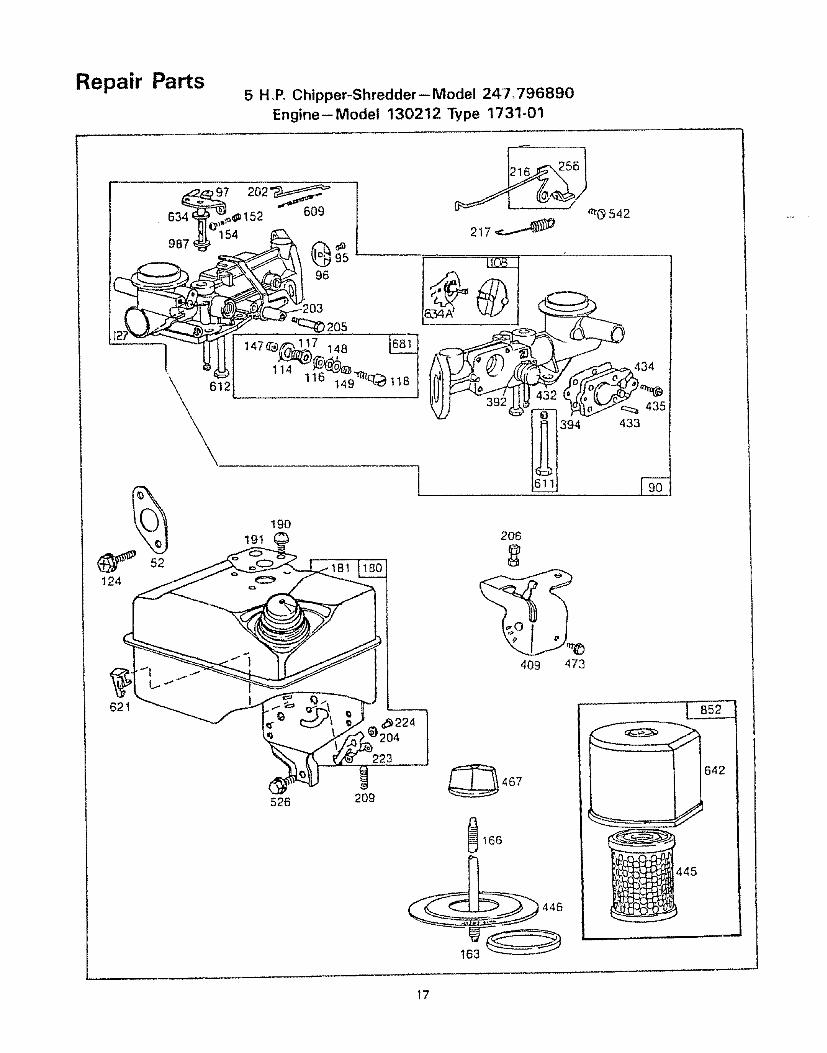
Repair Parts5 H,P. Chipper-ShredderiModel 247,796890
Engine--Model 130212 Type 1731-01
124
634_e_e,,_ 152 609 u_ _ _(_ 542
03 205
\ 612 ]4u _ _ J '
lfi_b1394 433
191190
2O6
409 473
621
223
526 209
_166
642
445
446
163
17
Repair
KEYNO
12
35789
10tl12
13
14
T5
161819
202122
232425
PISTON
26
2728
29
30
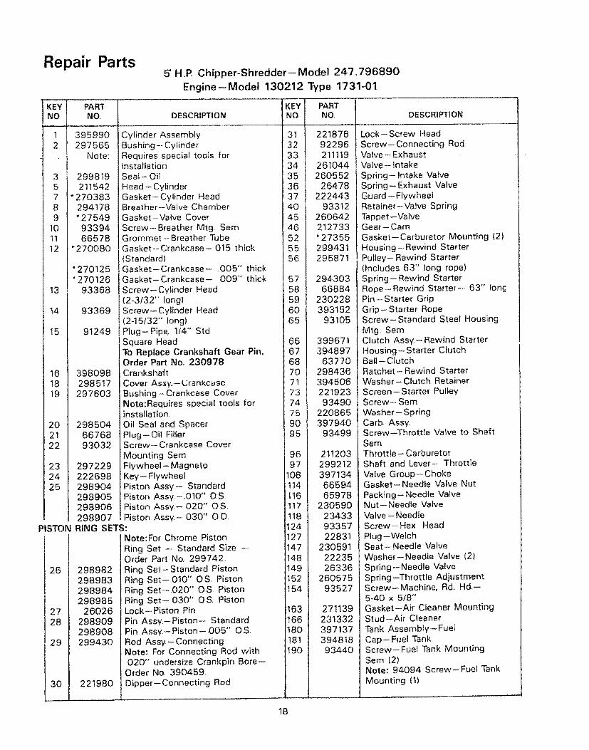
Parts5' H.P_ Chipper-Shredder-- Model 247,796890
Engine-Model 130212 Type 1731-01
PAR3"NO. DESCRIPTION
395990 Cylinder Assembly297565 Bushing-- Cylinder
Note: Requires special tools forinstallation
299819 Seal-- Oil
211542 Head-Cylinder* 270383 Gasket-Cylinder Head
294178 Breather-Valve Chamber"27549 Gasket-Valve Cover
93394 Screw--Breather Mtg Sam66578 Grommet-Breather Tube
"27OO80 Gasket--Crankcase-015 thickStandard)
"270125 Gasket-Crankcase- 005" thick"270126 Gasket-Crankcase- 009"' thick
93368 Screw-Cylinder Head(2-3/32" long)
93369 Screw--Cylinder Head(2-15/32" long)
91249 Plug-Pipe, 1/4" StdSquare HeadTo Replace Crankshaft Gear Pin,Order Part No,, 230978
398098 Crankshaft298517 Cover Assy.,-- €.;rankcasc
297603 Bushing--Crankcase CoverNote:Requires special tools for
}nsta!lation298504 Oil Seal and Spacer
66768 Plug--Oil Filler93032 Screw- Crankcase Cover
Mounting Sere297229 Flywheel-Magneto222698 Key--Flywheel298904 Piston Assy-- Standard298905 Piston Assy,-,010" O,S298906 Piston Ass_z,- O20" OS298907 Piston Ass,/,- 030" O DRING SETS:
Note:For Chrome Piston
Ring Set - Standard Size -=Order Part No. 299742,
298982 Ring Set-Standard Piston298983 Ring Set-010" OS Piston298984 Ring Set-,020" O.S Piston298985 Ring Set-030" OS. Piston
26026 Lock-- Piston Pin
298909 Pin Assy-Piston- Standard298908 Pin Assy.-Piston-005" 0S,299430 Rod Assy- Connecting
Note: For Connecting Rod with,020" undersize Crankpin Bore--Order No. 390459,
221980 Dipper--Connecting Rod
'KNE'_ PARTNO
32 92296211119
261044
26478
40 9331245 26064246 21273352 "27355
299431295871
66884230228
193105
.39489768 6377070 29843671 39450673 22192374 9349075
9O95
9697
108
1114|/!16 1[ 17 !!118/1124 |I 1f147/1148Ih49 1
t154 1
163 |t66 |
t8o /
Ig;l
22086539794093499
2112032992123971346659465978
230590234339335722831
2305912223526336
26057593527
27113923133239713739481893440
DESCRIPTION
Lock- Screw Head
Screw-- Connecting RodValve-ExhaustValve- Intake
Spring- Intake VaNeSpring- Exhaust ValveGuard - Flywheel
Retainer-Valve SpringTappet --ValveGear-Cam
Gasket-Carburetor Mounting (2)Housing- Rewind StarterPulley- Rewind Starter(Includes 63" long rope)Spring- Rewind StarterRope--Rewind Starter-- 63" IoncPin-Starter GripGrip-Starter RopeScrew-Standard Steel HousingMtg. SemClutch Assy-Rewind StarterHousing- Starter ClutchBali - ClutchRatchet- Rewind StarterWasher-Clutch Retainer
Screen- Starter PulleyScrew- Sem
Washer- SpringCarb AssyScrew--Throttle Valve to Shaft
SereThrottle- CarburetorShaft and Lever- Throttle
Valve Group- ChokeGasket-Needle Valve Nut
Packing-- Needle ValveNut- Needle ValveValve -- NeedleScrew-Hex Head
Plug --WelchSeat- Needle Valve
Washer--Needle Valve (2)Spring-Needle ValveSpring--Throttle AdjustmentScrew-Machine, Rd., Hd_--5-40 x 5f8"Gasket-Air Cleaner MountingStud-Air Cleaner
Tank AssembJy-FueJCap-Fuel TankScrew-- Fuel Tank MountingSem (2)Note: 94094 Screw-Fuel Tank
Mounting fl)
18

Repair Parts5 H°P. Chipper-Shredder--Model 247.796890
Engine--Model 130212 Type 1731-01
KEYNO.
191
200201202203204205206208
209 l2162172191220223224
227_230i256298299304305306307
308333335337
346356358363
373383392394409432433434
PARTNO.
"271592221480261558260678393919222962
9383828001223094626069539770926195139173722155122151793491
39392022245O39770926140939336829941093158
22151193042
221512
39735893414
DESCRIPTION
Gasket- Fuel Tank MountingGuide-AirLink- GovernorLink -Throttle ......Crank- Belt
Bushing--Governor Lever [Flat)Screw- ShoulderNut-Control RodRod- Control
Spring- GovernorLink-Choke (Includes Bell Crank)
Spring-ChokeGear- GovernorWasher-ThrustLever-Governor ControlRivet-Governor Control Lever
MountingLever Assy - GovernorWasher- Governor LeverCrank--Bell (Includes Choke Link)Locknut-- MufflerMuffler- Exhaust
Housing- BlowerScrew-Blower Housing MountingShield - Cylinder
Screw-Cylinder Shield MountingSem
Cover- Cylinder HeadArmature AssemblyScrew--Armature Mtg Sere
KEYNO,
435445
446467473526
527528529541542552
5625926086096tt612614
615616621
634634A642655
PARTNO
93141396424271466
222844212706
93612933a3
221514231386
678382239894025
231079
926132310823904632602943918132968119330693307
231077297472271853270382223306222598
DESCRIPTION
Screw-Diaphragm CoverCartridge--Air CleanerFoam Pre-Cleaner Element(not shown)
e,Jse -Air CleanerKnob Air CleanerScrew Sere
S_.,ew Tank Brackel MountingSere
Clamp Breathe_ TubeTube BreatherGrommet Bt'eathu, r TubeWasherScrew
Bushing G(_vmnor Crank(l,'4-I D)Bolt Governor LeverNut Hex 10 24
Starter Assy RewindSpring [hrotlle LinkFuel Pipe and Clip AssemblyPipe- FuelCotler, Hair Pm
Retainer E.RingCrank Governor (1/4" Dia)
Switch - StopWasher-Throttte Shaft (FoamlWasher Choke ShaftCover Air Cleaner
Anchor Spring298809
93705398808397145
19069
9398789838
Plug-Spark 1-112" High-37-42 MMScrew- SereWire- GroundGasket Set
Flywheel Puller (OptionalAccessoryNut-Hex
Wrench- Spark Plug
676
681725741851852869870
395700
299060223334261696221798
396397211787211172
Deflector Exhaust [DirectOuttet)Needle Valve KitShield- Heat
Gear TimingCable Terminal -- IgnitionCleaner Group- AirSeat - Intake Valve (Standard)Seat -Exhaust Valve (Standan)
26045527002629983722137793265
210959
Spring-Fuel Pump Diaphragm
DiaphragmLever-Trol- Speed ControlCap- SpringPin-Diaphragm CoverCover-- Diaphragm
871
987988
231348
398970735-0639
Note: For Options see RepairManualGuide Exhaust VatveNote: 63709 Guide - Intake Valve
See Repair Instruction ManuaSeal Tilrottle Shaft
Spark Plug Elbow
"Included in Gasket SetPart No. 39714&
SPARK ARRESTING MUFFLER ASSEMBLY
(Optional Equipment}
Consists of the following:392154 Screen (1 required)223372 Deflector (1 required)93705 Screw (4 required)
392390
t9

,£'_._/_/,e,@OWNERSMANUAL
MODEL NO.247.796890
HOW TO ORDERREPAIR PARTS
@_/_/,_,@/ CRRFT.SM AN®
5 H.P.CHIPPER-SHREDDER
The model number will be found on the model plate, attached to theframe Always mention the model number when requesting serviceor repair parts for your chipper-shredder
All parts listed herein may be ordered from any Sears Service Centerand most Sears stores
WHEN ORDERING REPAIR PARTS, ALWAYS GIVE THE FOLLOW-
ING INFORMATION:
• THE PART NUMBER
• THE PART DESCRIPTION
• THE MODEL NUMBER 247 796890• THE NAME OF MERCHANDISE--CHIPPER-SHREDDER
If the parts you need are not stocked locally, your order will be elec-tronically transmitted to a Sears Repair Parts Distribution Center forhandling
i u illu,
Sears, Roebuck and Co, Chicago, tlt 60684 U S A
PRINTED IN U S A PART NO 770-5875B(248.650-099) 8187