5: datalink layer 5-1 chapter 5 link layer and lans a note on the use of these ppt slides: all...
TRANSCRIPT
5 DataLink Layer 5-1
Chapter 5Link Layer and LANs
A note on the use of these ppt slides
All material copyright 1996-2007JF Kurose and KW Ross All Rights Reserved
Computer Networking A Top Down Approach
4th edition Jim Kurose Keith
RossAddison-Wesley July
2007
Link Layer 51 Introduction and
services 52 Error detection and
correction 53 Multiple access
protocols 54 Link-Layer Addressing 55 Ethernet
56 Hubs and switches 57 PPP
5 DataLink Layer 5-2
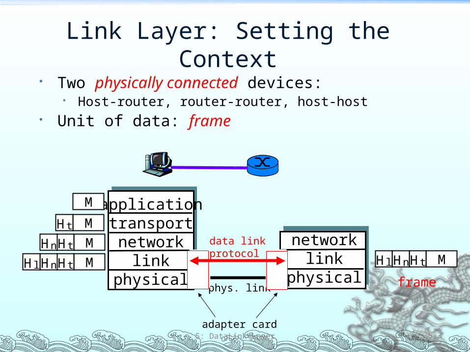
Link Layer Setting the Context Two physically connected devices
Host-router router-router host-host Unit of data frame
5 DataLink Layer 5-3
applicationtransportnetwork
linkphysical
networklink
physical
M
M
M
M
Ht
HtHn
HtHnHl MHtHnHl
framephys link
data linkprotocol
adapter card
Link Layer Services Framing link access
Encapsulate datagram into frame adding header trailer Channel access if shared medium ldquoMACrdquo addresses used in frame headers to identify source dest
Different from IP address
Reliable delivery between adjacent nodes We learned how to do this already (chapter 3) Seldom used on low bit error link (fiber some twisted pair) Wireless links high error rates
Q why both link-level and end-end reliability
5 DataLink Layer 5-4
Link Layer Services (more) Flow Control
Pacing between adjacent sending and receiving nodes
Error Detection Errors caused by signal attenuation noise Receiver detects presence of errors
Signals sender for retransmission or drops frame Error Correction
Receiver identifies and corrects bit error(s) without resorting to retransmission
Half-duplex and full-duplex With half duplex nodes at both ends of link can transmit but not at
same time
5 DataLink Layer 5-5
Link Layer 51 Introduction and
services 52 Error detection and
correction 53Multiple access
protocols 54 Link-Layer Addressing 55 Ethernet
56 Hubs and switches 57 PPP
5 DataLink Layer 5-6
Error Detection
5 DataLink Layer 5-7
EDC= Error Detection and Correction bits (redundancy)D = Data protected by error checking may include header fields
bull Error detection not 100 reliablebull Protocol may miss some errors but rarelybull Larger EDC field yields better detection and correction
Checksumming Cyclic Redundancy Check
View data bits D as a binary number Choose r+1 bit pattern (generator) G Goal choose r CRC bits R such that
ltDRgt exactly divisible (polynomial division) by G (modulo 2) Receiver knows G divides ltDRgt by G If non-zero remainder error
detected Can detect all burst errors less than r+1 bits
Widely used in practice (ATM HDLC)
5 DataLink Layer 5-8
CRC ExampleWant
D2r XOR R = nGequivalently
D2r = nG XOR R equivalently
if we divide D2r by G want remainder R
5 DataLink Layer 5-9
R = remainder[ ]D2r
G
Link Layer 51 Introduction and
services 52 Error detection and
correction 53 Multiple access
protocols 54 Link-Layer Addressing 55 Ethernet
56 Hubs and switches 57 PPP
5 DataLink Layer 5-10
Multiple Access Links and Protocols
Two types of ldquolinksrdquo Point-to-point
PPP for dial-up access Point-to-point link between Ethernet switch and host
Broadcast (shared wire or medium) Old-fashioned Ethernet Upstream HFC 80211 wireless LAN
5 DataLink Layer 5-11
Multiple Access protocols Single shared broadcast channel Two or more simultaneous transmissions by nodes
interference Collision if node receives two or more signals at the same time
Multiple access protocol Distributed algorithm that determines how nodes share
channel ie determine when node can transmit Communication about channel sharing must use channel
itself No out-of-band channel for coordination
5 DataLink Layer 5-12
Ideal Multiple Access Protocol
Broadcast channel of rate R bps1 When one node wants to transmit it can send at rate R
2 When M nodes want to transmit each can send at average rate RM
3 Fully decentralized No special node to coordinate transmissions No synchronization of clocks slots
4 Simple
5 DataLink Layer 5-13
MAC Protocols a Taxonomy
Three broad classes Channel Partitioning TDMA FDMA CDMA (in wireless)
Divide channel into smaller ldquopiecesrdquo (time slots frequency code)
Allocate piece to node for exclusive use
Random Access ALOHA CSMA CSMACD CSMACA Channel not divided allow collisions ldquoRecoverrdquo from collisions
ldquoTaking turnsrdquo Polling Token passing Nodes take turns but nodes with more to send can take longer
turns
5 DataLink Layer 5-14
Random Access Protocols When node has packet to send
Transmit at full channel data rate R No a priori coordination among nodes
Two or more transmitting nodes ldquocollisionrdquo Random access MAC protocol specifies
How to detect collisions How to recover from collisions (eg via delayed retransmissions)
Examples of random access MAC protocols Slotted ALOHA ALOHA CSMA CSMACD CSMACA
5 DataLink Layer 5-15
Slotted ALOHA
Assumptions All frames same size Time is divided into equal
size slots time to transmit 1 frame
Nodes start to transmit frames only at beginning of slots
Nodes are synchronized If 2 or more nodes
transmit in slot all nodes detect collision
Operation When node obtains fresh
frame it transmits in next slot
No collision node can send new frame in next slot
If collision node retransmits frame in each subsequent slot with prob p until success
5 DataLink Layer 5-16
Slotted ALOHA
Pros Single active node can
continuously transmit at full rate of channel
Highly decentralized only slots in nodes need to be in sync
Simple
Cons Collisions wasting slots Idle slots Nodes may be able to
detect collision in less than time to transmit packet
Clock synchronization
5 DataLink Layer 5-17
Pure (Unslotted) ALOHA Unslotted Aloha simpler no synchronization When frame first arrives
Transmit immediately Collision probability increases
Frame sent at t0 collides with other frames sent in [t0-1t0+1]
5 DataLink Layer 5-18
CSMA (Carrier Sense Multiple Access)
CSMA listen before transmitThis is Carrier Sensing
If channel sensed idle transmit entire frame If channel sensed busy defer transmission
Human analogy donrsquot interrupt others
5 DataLink Layer 5-19
If someone else is already transmitting then back off (wait) until channel is free Wait how long
If collision is detected during transmission then must retransmit the frame When is it retransmitted
CSMA (Carrier Sense Multiple Access)
1-Persistent CSMA If channel sensed idle transmit entire pkt If channel sensed busy wait until channel becomes idle and then transmit
right away If collision occurs wait random time and then restart process
Non-persistent CSMA (for nonslotted channels) If channel sensed idle transmit entire pkt If channel sensed busy wait random time before trying again If collision occurs wait random time and then restart process
P-Persistent CSMA (for slotted channels) If channel sensed idle then with probability p transmit in current slot
With probability q=1-p wait until next slot and try again (with probability p)
If channel sensed busy wait until next slot and try again If collision occurs wait random time and then restart process
5 DataLink Layer 5-20
CSMA Collisions
5 DataLink Layer 5-21
Collisions can still occurpropagation delay means two nodes may not heareach otherrsquos transmissionCollisionentire packet transmission time wasted
spatial layout of nodes
Noterole of distance amp propagation delay in determining collision probability
CSMACD (Collision Detection)
CSMACD carrier sensing deferral as in CSMA
Collisions detected within short time Colliding transmissions aborted
reducing channel wastage Collision detection
Easy in wired LANs measure signal strengths compare transmitted received signals
Difficult in wireless LANs receiver shut off while transmitting
5 DataLink Layer 5-22
ldquoTaking Turnsrdquo MAC protocols
Channel partitioning MAC protocols Share channel efficiently and fairly at high load Inefficient at low load delay in channel access 1N
bandwidth allocated even if only 1 active node
Random access MAC protocols Efficient at low load single node can fully utilize channel High load collision overhead
ldquoTaking turnsrdquo protocolsLook for best of both worlds
5 DataLink Layer 5-23
ldquoTaking Turnsrdquo MAC protocols
Polling Master node ldquoinvitesrdquo
slave nodes to transmit in turn
Concerns Polling overhead Latency Single point of failure
(master)
5 DataLink Layer 5-24
Token passing Control token passed from one
node to next sequentially Token message Concerns
Token overhead Latency Single point of failure (token)
Summary of MAC Protocols What do you do with a shared media
Channel Partitioning by time frequency or code Time Division Frequency Division
Random partitioning (dynamic) ALOHA S-ALOHA CSMA CSMACD Carrier sensing easy in some technologies (wire) hard in
others (wireless) CSMACD used in Ethernet CSMACA used in 80211
Taking Turns Polling from a central site token passing
5 DataLink Layer 5-25
LAN TechnologiesData link layer so far
Services error detectioncorrection multiple access
Next LAN technologies Addressing Ethernet Hubs switches IEEE 80211 (wireless) PPP
5 DataLink Layer 5-26
LAN
Router
Link Layer 51 Introduction and
services 52 Error detection and
correction 53 Multiple access
protocols 54 Link-Layer Addressing 55 Ethernet
56 Hubs and switches 57 PPP
5 DataLink Layer 5-27
MAC Addresses and ARP
32-bit IP address Network-layer address Used to get datagram to destination IP subnet
MAC (or LAN or physical or Ethernet) address Used to get frame from one interface to another
physically-connected interface (same network) 48 bit MAC address (for most LANs)
burned in the adapter ROM
5 DataLink Layer 5-28
LAN Addresses and ARP
5 DataLink Layer 5-29
Each adapter on LAN has unique LAN address
Broadcast address =FF-FF-FF-FF-FF-FF
= adapter
1A-2F-BB-76-09-AD
58-23-D7-FA-20-B0
0C-C4-11-6F-E3-98
71-65-F7-2B-08-53
LAN(wired orwireless)
Recall Earlier Routing Discussion
5 DataLink Layer 5-30
223111
223112
223113
223114 223129
223122
223121
223132223131
2231327
A
BE
Starting at A given IP datagram addressed to B
Look up net address of B find B on same net as A
Link layer send datagram to B inside link-layer frame
Brsquos MACaddr
Arsquos MACaddr
Arsquos IPaddr
Brsquos IPaddr
IP payload
datagramframe
frame sourcedest address
datagram sourcedest address
ARP Address Resolution Protocol
Each IP node (Host Router) on LAN has ARP table
ARP Table IPMAC address mappings for some LAN nodes
lt IP address MAC address TTLgt TTL (Time To Live) time
after which address mapping will be forgotten (typically 20 min)
5 DataLink Layer 5-31
Question how to determineMAC address of B knowing Brsquos IP address
1A-2F-BB-76-09-AD
58-23-D7-FA-20-B0
0C-C4-11-6F-E3-98
71-65-F7-2B-08-53
LAN
137196723
137196778
137196714
137196788
ARP Protocol Same LAN (network)
A wants to send datagram to B and Brsquos MAC address not in Arsquos ARP table
A broadcasts ARP query packet containing Bs IP address
Dest MAC address = FF-FF-FF-FF-FF-FF
All machines on LAN receive ARP query
B receives ARP packet replies to A with its (Bs) MAC address
Frame sent to Arsquos MAC address (unicast)
A caches (saves) IP-to-MAC address pair in its ARP table until information becomes old (times out)
Soft state information that times out (goes away) unless refreshed
ARP is ldquoplug-and-playrdquo Nodes create their ARP
tables without intervention from net administrator
5 DataLink Layer 5-32
Link Layer 51 Introduction and
services 52 Error detection and
correction 53 Multiple access
protocols 54 Link-Layer Addressing 55 Ethernet
56 Hubs and switches 57 PPP
5 DataLink Layer 5-33
EthernetldquoDominantrdquo wired LAN technology Cheap $20 for 100Mbs First widely used LAN technology Simpler cheaper than token LANs and ATM Kept up with speed race 10 Mbps ndash 10 Gbps
5 DataLink Layer 5-34
Metcalfersquos Ethernetsketch
Star Topology Bus topology popular through mid 90s Now star topology prevails Connection choices hub or switch (more later)
5 DataLink Layer 5-35
hub orswitch
Ethernet uses CSMACD No slots Adapter doesnrsquot transmit if
it senses that some other adapter is transmitting that is carrier sense
Transmitting adapter aborts when it senses that another adapter is transmitting that is collision detection
Before attempting a retransmission adapter waits a random time that is random access
5 DataLink Layer 5-36
random time depends upon collisions so far
Ethernet CSMACD Algorithm
1 Adaptor receives datagram from network layer amp creates frame
2 If adapter senses channel idle it starts to transmit frame If it senses channel busy waits until channel idle and then transmits
3 If adapter transmits entire frame without detecting another transmission the adapter is done with frame
4 If adapter detects another transmission while transmitting aborts and sends jam signal
5 After aborting adapter enters exponential backoff after the mth collision adapter chooses a K at random from 012hellip2m-1 Adapter waits K512 bit times and returns to Step 2
5 DataLink Layer 5-37
Ethernetrsquos CSMACD (more)Jam Signal make sure all other
transmitters are aware of collision 48 bits
Bit time 1 microsec for 10 Mbps Ethernet for K=1023 wait time is about 50 msec
Exponential Backoff Goal adapt retransmission
attempts to estimated current load
Heavy load random wait will be longer
First collision choose K from 01 delay is K 512 bit transmission times
After second collision choose K from 0123hellip
After ten collisions choose K from 01234hellip1023
5 DataLink Layer 5-38
Link Layer 51 Introduction and
services 52 Error detection and
correction 53Multiple access
protocols 54 Link-Layer Addressing 55 Ethernet
56 Interconnections Hubs and switches
57 PPP
5 DataLink Layer 5-39
Hubs Physical Layer devices essentially repeaters operating
at bit levels repeat received bits on one interface to all other interfaces
Hubs can be arranged in a hierarchy (or multi-tier design) with backbone hub at its top
5 DataLink Layer 5-40
hub
hubhub
hub
Hubs (more)
Each connected LAN referred to as LAN segment Hubs do not isolate collision domains node may
collide with any node residing at any segment in LAN Hub Advantages
Simple inexpensive device Multi-tier provides graceful degradation portions of
the LAN continue to operate if one hub malfunctions Extends maximum distance between node pairs (100m
per Hub)
5 DataLink Layer 5-41
Hub Limitations Single collision domain results in no increase in max
throughput Multi-tier throughput same as single segment
throughput Individual LAN restrictions pose limits on number of nodes
in same collision domain and on total allowed geographical coverage
Cannot connect different Ethernet types (eg 10BaseT and 100baseT)
We now move on to switches
5 DataLink Layer 5-42
Switch Link layer device
Stores and forwards Ethernet frames Examines frame header and selectively forwards frame
based on MAC dest address When frame is to be forwarded on segment uses
CSMACD to access segment Transparent
Hosts are unaware of presence of switches Plug-and-play self-learning
Switches do not need to be configured
5 DataLink Layer 5-43
Switch Traffic Isolation Switch installation breaks subnet into LAN segments Switch filters packets
Same-LAN-segment frames not usually forwarded onto other LAN segments
Segments become separate collision domains
5 DataLink Layer 5-44
hub hub hub
switch
collision domain collision domain
collision domain
Switch Forwarding
5 DataLink Layer 5-45
How do determine onto which LAN segment to forward frame
Looks like a routing problem
hub
hubhub
switch1
2 3
Switch Self Learning A switch has a switch table Entry in switch table
(MAC Address Interface Time Stamp) Stale entries in table dropped (TTL can be 60 min)
Switch learns which hosts can be reached through which interfaces
When frame received switch ldquolearnsrdquo location of sender incoming LAN segment
Records senderlocation pair in switch table
5 DataLink Layer 5-46
Switch FilteringForwarding
When switch receives a frame
Index switch table using MAC dest address
if entry found for destinationthen
if dest on segment from which frame arrived then drop the frame
else forward the frame on interface indicated
else flood
5 DataLink Layer 5-47
forward on all but the interface on which the frame arrived
Switch Example
Suppose C sends frame to D
5 DataLink Layer 5-48
Switch receives frame from from C Notes in switch table that C is on interface 1 Because D is not in table switch forwards frame into interfaces
2 and 3
Frame received by D
hub
hub hub
switch
A
B CD
EF
G H
I
address interface
ABEG
1123
12 3
Switch Example
Suppose D replies back with frame to C
5 DataLink Layer 5-49
Switch receives frame from from D Notes in switch table that D is on interface 2 Because C is in table switch forwards frame only to interface 1
Frame received by C
hub
hub hub
switch
A
B CD
EF
G H
I
address interface
ABEGC
11231
Institutional Network
5 DataLink Layer 5-50
hub
hubhub
switch
to externalnetwork
router
IP subnet
mail server
web server
Chapter 5 Summary Principles behind data link layer services
Error detection correction Sharing a broadcast channel multiple access Link layer addressing
Instantiation and implementation of various link layer technologies
Ethernet Hubs switches IEEE 80211 (detailed see next Chapter) PPP
5 DataLink Layer 5-51
Link Layer 51 Introduction and
services 52 Error detection and
correction 53 Multiple access
protocols 54 Link-Layer Addressing 55 Ethernet
56 Hubs and switches 57 PPP
5 DataLink Layer 5-2
Link Layer Setting the Context Two physically connected devices
Host-router router-router host-host Unit of data frame
5 DataLink Layer 5-3
applicationtransportnetwork
linkphysical
networklink
physical
M
M
M
M
Ht
HtHn
HtHnHl MHtHnHl
framephys link
data linkprotocol
adapter card
Link Layer Services Framing link access
Encapsulate datagram into frame adding header trailer Channel access if shared medium ldquoMACrdquo addresses used in frame headers to identify source dest
Different from IP address
Reliable delivery between adjacent nodes We learned how to do this already (chapter 3) Seldom used on low bit error link (fiber some twisted pair) Wireless links high error rates
Q why both link-level and end-end reliability
5 DataLink Layer 5-4
Link Layer Services (more) Flow Control
Pacing between adjacent sending and receiving nodes
Error Detection Errors caused by signal attenuation noise Receiver detects presence of errors
Signals sender for retransmission or drops frame Error Correction
Receiver identifies and corrects bit error(s) without resorting to retransmission
Half-duplex and full-duplex With half duplex nodes at both ends of link can transmit but not at
same time
5 DataLink Layer 5-5
Link Layer 51 Introduction and
services 52 Error detection and
correction 53Multiple access
protocols 54 Link-Layer Addressing 55 Ethernet
56 Hubs and switches 57 PPP
5 DataLink Layer 5-6
Error Detection
5 DataLink Layer 5-7
EDC= Error Detection and Correction bits (redundancy)D = Data protected by error checking may include header fields
bull Error detection not 100 reliablebull Protocol may miss some errors but rarelybull Larger EDC field yields better detection and correction
Checksumming Cyclic Redundancy Check
View data bits D as a binary number Choose r+1 bit pattern (generator) G Goal choose r CRC bits R such that
ltDRgt exactly divisible (polynomial division) by G (modulo 2) Receiver knows G divides ltDRgt by G If non-zero remainder error
detected Can detect all burst errors less than r+1 bits
Widely used in practice (ATM HDLC)
5 DataLink Layer 5-8
CRC ExampleWant
D2r XOR R = nGequivalently
D2r = nG XOR R equivalently
if we divide D2r by G want remainder R
5 DataLink Layer 5-9
R = remainder[ ]D2r
G
Link Layer 51 Introduction and
services 52 Error detection and
correction 53 Multiple access
protocols 54 Link-Layer Addressing 55 Ethernet
56 Hubs and switches 57 PPP
5 DataLink Layer 5-10
Multiple Access Links and Protocols
Two types of ldquolinksrdquo Point-to-point
PPP for dial-up access Point-to-point link between Ethernet switch and host
Broadcast (shared wire or medium) Old-fashioned Ethernet Upstream HFC 80211 wireless LAN
5 DataLink Layer 5-11
Multiple Access protocols Single shared broadcast channel Two or more simultaneous transmissions by nodes
interference Collision if node receives two or more signals at the same time
Multiple access protocol Distributed algorithm that determines how nodes share
channel ie determine when node can transmit Communication about channel sharing must use channel
itself No out-of-band channel for coordination
5 DataLink Layer 5-12
Ideal Multiple Access Protocol
Broadcast channel of rate R bps1 When one node wants to transmit it can send at rate R
2 When M nodes want to transmit each can send at average rate RM
3 Fully decentralized No special node to coordinate transmissions No synchronization of clocks slots
4 Simple
5 DataLink Layer 5-13
MAC Protocols a Taxonomy
Three broad classes Channel Partitioning TDMA FDMA CDMA (in wireless)
Divide channel into smaller ldquopiecesrdquo (time slots frequency code)
Allocate piece to node for exclusive use
Random Access ALOHA CSMA CSMACD CSMACA Channel not divided allow collisions ldquoRecoverrdquo from collisions
ldquoTaking turnsrdquo Polling Token passing Nodes take turns but nodes with more to send can take longer
turns
5 DataLink Layer 5-14
Random Access Protocols When node has packet to send
Transmit at full channel data rate R No a priori coordination among nodes
Two or more transmitting nodes ldquocollisionrdquo Random access MAC protocol specifies
How to detect collisions How to recover from collisions (eg via delayed retransmissions)
Examples of random access MAC protocols Slotted ALOHA ALOHA CSMA CSMACD CSMACA
5 DataLink Layer 5-15
Slotted ALOHA
Assumptions All frames same size Time is divided into equal
size slots time to transmit 1 frame
Nodes start to transmit frames only at beginning of slots
Nodes are synchronized If 2 or more nodes
transmit in slot all nodes detect collision
Operation When node obtains fresh
frame it transmits in next slot
No collision node can send new frame in next slot
If collision node retransmits frame in each subsequent slot with prob p until success
5 DataLink Layer 5-16
Slotted ALOHA
Pros Single active node can
continuously transmit at full rate of channel
Highly decentralized only slots in nodes need to be in sync
Simple
Cons Collisions wasting slots Idle slots Nodes may be able to
detect collision in less than time to transmit packet
Clock synchronization
5 DataLink Layer 5-17
Pure (Unslotted) ALOHA Unslotted Aloha simpler no synchronization When frame first arrives
Transmit immediately Collision probability increases
Frame sent at t0 collides with other frames sent in [t0-1t0+1]
5 DataLink Layer 5-18
CSMA (Carrier Sense Multiple Access)
CSMA listen before transmitThis is Carrier Sensing
If channel sensed idle transmit entire frame If channel sensed busy defer transmission
Human analogy donrsquot interrupt others
5 DataLink Layer 5-19
If someone else is already transmitting then back off (wait) until channel is free Wait how long
If collision is detected during transmission then must retransmit the frame When is it retransmitted
CSMA (Carrier Sense Multiple Access)
1-Persistent CSMA If channel sensed idle transmit entire pkt If channel sensed busy wait until channel becomes idle and then transmit
right away If collision occurs wait random time and then restart process
Non-persistent CSMA (for nonslotted channels) If channel sensed idle transmit entire pkt If channel sensed busy wait random time before trying again If collision occurs wait random time and then restart process
P-Persistent CSMA (for slotted channels) If channel sensed idle then with probability p transmit in current slot
With probability q=1-p wait until next slot and try again (with probability p)
If channel sensed busy wait until next slot and try again If collision occurs wait random time and then restart process
5 DataLink Layer 5-20
CSMA Collisions
5 DataLink Layer 5-21
Collisions can still occurpropagation delay means two nodes may not heareach otherrsquos transmissionCollisionentire packet transmission time wasted
spatial layout of nodes
Noterole of distance amp propagation delay in determining collision probability
CSMACD (Collision Detection)
CSMACD carrier sensing deferral as in CSMA
Collisions detected within short time Colliding transmissions aborted
reducing channel wastage Collision detection
Easy in wired LANs measure signal strengths compare transmitted received signals
Difficult in wireless LANs receiver shut off while transmitting
5 DataLink Layer 5-22
ldquoTaking Turnsrdquo MAC protocols
Channel partitioning MAC protocols Share channel efficiently and fairly at high load Inefficient at low load delay in channel access 1N
bandwidth allocated even if only 1 active node
Random access MAC protocols Efficient at low load single node can fully utilize channel High load collision overhead
ldquoTaking turnsrdquo protocolsLook for best of both worlds
5 DataLink Layer 5-23
ldquoTaking Turnsrdquo MAC protocols
Polling Master node ldquoinvitesrdquo
slave nodes to transmit in turn
Concerns Polling overhead Latency Single point of failure
(master)
5 DataLink Layer 5-24
Token passing Control token passed from one
node to next sequentially Token message Concerns
Token overhead Latency Single point of failure (token)
Summary of MAC Protocols What do you do with a shared media
Channel Partitioning by time frequency or code Time Division Frequency Division
Random partitioning (dynamic) ALOHA S-ALOHA CSMA CSMACD Carrier sensing easy in some technologies (wire) hard in
others (wireless) CSMACD used in Ethernet CSMACA used in 80211
Taking Turns Polling from a central site token passing
5 DataLink Layer 5-25
LAN TechnologiesData link layer so far
Services error detectioncorrection multiple access
Next LAN technologies Addressing Ethernet Hubs switches IEEE 80211 (wireless) PPP
5 DataLink Layer 5-26
LAN
Router
Link Layer 51 Introduction and
services 52 Error detection and
correction 53 Multiple access
protocols 54 Link-Layer Addressing 55 Ethernet
56 Hubs and switches 57 PPP
5 DataLink Layer 5-27
MAC Addresses and ARP
32-bit IP address Network-layer address Used to get datagram to destination IP subnet
MAC (or LAN or physical or Ethernet) address Used to get frame from one interface to another
physically-connected interface (same network) 48 bit MAC address (for most LANs)
burned in the adapter ROM
5 DataLink Layer 5-28
LAN Addresses and ARP
5 DataLink Layer 5-29
Each adapter on LAN has unique LAN address
Broadcast address =FF-FF-FF-FF-FF-FF
= adapter
1A-2F-BB-76-09-AD
58-23-D7-FA-20-B0
0C-C4-11-6F-E3-98
71-65-F7-2B-08-53
LAN(wired orwireless)
Recall Earlier Routing Discussion
5 DataLink Layer 5-30
223111
223112
223113
223114 223129
223122
223121
223132223131
2231327
A
BE
Starting at A given IP datagram addressed to B
Look up net address of B find B on same net as A
Link layer send datagram to B inside link-layer frame
Brsquos MACaddr
Arsquos MACaddr
Arsquos IPaddr
Brsquos IPaddr
IP payload
datagramframe
frame sourcedest address
datagram sourcedest address
ARP Address Resolution Protocol
Each IP node (Host Router) on LAN has ARP table
ARP Table IPMAC address mappings for some LAN nodes
lt IP address MAC address TTLgt TTL (Time To Live) time
after which address mapping will be forgotten (typically 20 min)
5 DataLink Layer 5-31
Question how to determineMAC address of B knowing Brsquos IP address
1A-2F-BB-76-09-AD
58-23-D7-FA-20-B0
0C-C4-11-6F-E3-98
71-65-F7-2B-08-53
LAN
137196723
137196778
137196714
137196788
ARP Protocol Same LAN (network)
A wants to send datagram to B and Brsquos MAC address not in Arsquos ARP table
A broadcasts ARP query packet containing Bs IP address
Dest MAC address = FF-FF-FF-FF-FF-FF
All machines on LAN receive ARP query
B receives ARP packet replies to A with its (Bs) MAC address
Frame sent to Arsquos MAC address (unicast)
A caches (saves) IP-to-MAC address pair in its ARP table until information becomes old (times out)
Soft state information that times out (goes away) unless refreshed
ARP is ldquoplug-and-playrdquo Nodes create their ARP
tables without intervention from net administrator
5 DataLink Layer 5-32
Link Layer 51 Introduction and
services 52 Error detection and
correction 53 Multiple access
protocols 54 Link-Layer Addressing 55 Ethernet
56 Hubs and switches 57 PPP
5 DataLink Layer 5-33
EthernetldquoDominantrdquo wired LAN technology Cheap $20 for 100Mbs First widely used LAN technology Simpler cheaper than token LANs and ATM Kept up with speed race 10 Mbps ndash 10 Gbps
5 DataLink Layer 5-34
Metcalfersquos Ethernetsketch
Star Topology Bus topology popular through mid 90s Now star topology prevails Connection choices hub or switch (more later)
5 DataLink Layer 5-35
hub orswitch
Ethernet uses CSMACD No slots Adapter doesnrsquot transmit if
it senses that some other adapter is transmitting that is carrier sense
Transmitting adapter aborts when it senses that another adapter is transmitting that is collision detection
Before attempting a retransmission adapter waits a random time that is random access
5 DataLink Layer 5-36
random time depends upon collisions so far
Ethernet CSMACD Algorithm
1 Adaptor receives datagram from network layer amp creates frame
2 If adapter senses channel idle it starts to transmit frame If it senses channel busy waits until channel idle and then transmits
3 If adapter transmits entire frame without detecting another transmission the adapter is done with frame
4 If adapter detects another transmission while transmitting aborts and sends jam signal
5 After aborting adapter enters exponential backoff after the mth collision adapter chooses a K at random from 012hellip2m-1 Adapter waits K512 bit times and returns to Step 2
5 DataLink Layer 5-37
Ethernetrsquos CSMACD (more)Jam Signal make sure all other
transmitters are aware of collision 48 bits
Bit time 1 microsec for 10 Mbps Ethernet for K=1023 wait time is about 50 msec
Exponential Backoff Goal adapt retransmission
attempts to estimated current load
Heavy load random wait will be longer
First collision choose K from 01 delay is K 512 bit transmission times
After second collision choose K from 0123hellip
After ten collisions choose K from 01234hellip1023
5 DataLink Layer 5-38
Link Layer 51 Introduction and
services 52 Error detection and
correction 53Multiple access
protocols 54 Link-Layer Addressing 55 Ethernet
56 Interconnections Hubs and switches
57 PPP
5 DataLink Layer 5-39
Hubs Physical Layer devices essentially repeaters operating
at bit levels repeat received bits on one interface to all other interfaces
Hubs can be arranged in a hierarchy (or multi-tier design) with backbone hub at its top
5 DataLink Layer 5-40
hub
hubhub
hub
Hubs (more)
Each connected LAN referred to as LAN segment Hubs do not isolate collision domains node may
collide with any node residing at any segment in LAN Hub Advantages
Simple inexpensive device Multi-tier provides graceful degradation portions of
the LAN continue to operate if one hub malfunctions Extends maximum distance between node pairs (100m
per Hub)
5 DataLink Layer 5-41
Hub Limitations Single collision domain results in no increase in max
throughput Multi-tier throughput same as single segment
throughput Individual LAN restrictions pose limits on number of nodes
in same collision domain and on total allowed geographical coverage
Cannot connect different Ethernet types (eg 10BaseT and 100baseT)
We now move on to switches
5 DataLink Layer 5-42
Switch Link layer device
Stores and forwards Ethernet frames Examines frame header and selectively forwards frame
based on MAC dest address When frame is to be forwarded on segment uses
CSMACD to access segment Transparent
Hosts are unaware of presence of switches Plug-and-play self-learning
Switches do not need to be configured
5 DataLink Layer 5-43
Switch Traffic Isolation Switch installation breaks subnet into LAN segments Switch filters packets
Same-LAN-segment frames not usually forwarded onto other LAN segments
Segments become separate collision domains
5 DataLink Layer 5-44
hub hub hub
switch
collision domain collision domain
collision domain
Switch Forwarding
5 DataLink Layer 5-45
How do determine onto which LAN segment to forward frame
Looks like a routing problem
hub
hubhub
switch1
2 3
Switch Self Learning A switch has a switch table Entry in switch table
(MAC Address Interface Time Stamp) Stale entries in table dropped (TTL can be 60 min)
Switch learns which hosts can be reached through which interfaces
When frame received switch ldquolearnsrdquo location of sender incoming LAN segment
Records senderlocation pair in switch table
5 DataLink Layer 5-46
Switch FilteringForwarding
When switch receives a frame
Index switch table using MAC dest address
if entry found for destinationthen
if dest on segment from which frame arrived then drop the frame
else forward the frame on interface indicated
else flood
5 DataLink Layer 5-47
forward on all but the interface on which the frame arrived
Switch Example
Suppose C sends frame to D
5 DataLink Layer 5-48
Switch receives frame from from C Notes in switch table that C is on interface 1 Because D is not in table switch forwards frame into interfaces
2 and 3
Frame received by D
hub
hub hub
switch
A
B CD
EF
G H
I
address interface
ABEG
1123
12 3
Switch Example
Suppose D replies back with frame to C
5 DataLink Layer 5-49
Switch receives frame from from D Notes in switch table that D is on interface 2 Because C is in table switch forwards frame only to interface 1
Frame received by C
hub
hub hub
switch
A
B CD
EF
G H
I
address interface
ABEGC
11231
Institutional Network
5 DataLink Layer 5-50
hub
hubhub
switch
to externalnetwork
router
IP subnet
mail server
web server
Chapter 5 Summary Principles behind data link layer services
Error detection correction Sharing a broadcast channel multiple access Link layer addressing
Instantiation and implementation of various link layer technologies
Ethernet Hubs switches IEEE 80211 (detailed see next Chapter) PPP
5 DataLink Layer 5-51
Link Layer 51 Introduction and
services 52 Error detection and
correction 53Multiple access
protocols 54 Link-Layer Addressing 55 Ethernet
56 Hubs and switches 57 PPP
5 DataLink Layer 5-6
Error Detection
5 DataLink Layer 5-7
EDC= Error Detection and Correction bits (redundancy)D = Data protected by error checking may include header fields
bull Error detection not 100 reliablebull Protocol may miss some errors but rarelybull Larger EDC field yields better detection and correction
Checksumming Cyclic Redundancy Check
View data bits D as a binary number Choose r+1 bit pattern (generator) G Goal choose r CRC bits R such that
ltDRgt exactly divisible (polynomial division) by G (modulo 2) Receiver knows G divides ltDRgt by G If non-zero remainder error
detected Can detect all burst errors less than r+1 bits
Widely used in practice (ATM HDLC)
5 DataLink Layer 5-8
CRC ExampleWant
D2r XOR R = nGequivalently
D2r = nG XOR R equivalently
if we divide D2r by G want remainder R
5 DataLink Layer 5-9
R = remainder[ ]D2r
G
Link Layer 51 Introduction and
services 52 Error detection and
correction 53 Multiple access
protocols 54 Link-Layer Addressing 55 Ethernet
56 Hubs and switches 57 PPP
5 DataLink Layer 5-10
Multiple Access Links and Protocols
Two types of ldquolinksrdquo Point-to-point
PPP for dial-up access Point-to-point link between Ethernet switch and host
Broadcast (shared wire or medium) Old-fashioned Ethernet Upstream HFC 80211 wireless LAN
5 DataLink Layer 5-11
Multiple Access protocols Single shared broadcast channel Two or more simultaneous transmissions by nodes
interference Collision if node receives two or more signals at the same time
Multiple access protocol Distributed algorithm that determines how nodes share
channel ie determine when node can transmit Communication about channel sharing must use channel
itself No out-of-band channel for coordination
5 DataLink Layer 5-12
Ideal Multiple Access Protocol
Broadcast channel of rate R bps1 When one node wants to transmit it can send at rate R
2 When M nodes want to transmit each can send at average rate RM
3 Fully decentralized No special node to coordinate transmissions No synchronization of clocks slots
4 Simple
5 DataLink Layer 5-13
MAC Protocols a Taxonomy
Three broad classes Channel Partitioning TDMA FDMA CDMA (in wireless)
Divide channel into smaller ldquopiecesrdquo (time slots frequency code)
Allocate piece to node for exclusive use
Random Access ALOHA CSMA CSMACD CSMACA Channel not divided allow collisions ldquoRecoverrdquo from collisions
ldquoTaking turnsrdquo Polling Token passing Nodes take turns but nodes with more to send can take longer
turns
5 DataLink Layer 5-14
Random Access Protocols When node has packet to send
Transmit at full channel data rate R No a priori coordination among nodes
Two or more transmitting nodes ldquocollisionrdquo Random access MAC protocol specifies
How to detect collisions How to recover from collisions (eg via delayed retransmissions)
Examples of random access MAC protocols Slotted ALOHA ALOHA CSMA CSMACD CSMACA
5 DataLink Layer 5-15
Slotted ALOHA
Assumptions All frames same size Time is divided into equal
size slots time to transmit 1 frame
Nodes start to transmit frames only at beginning of slots
Nodes are synchronized If 2 or more nodes
transmit in slot all nodes detect collision
Operation When node obtains fresh
frame it transmits in next slot
No collision node can send new frame in next slot
If collision node retransmits frame in each subsequent slot with prob p until success
5 DataLink Layer 5-16
Slotted ALOHA
Pros Single active node can
continuously transmit at full rate of channel
Highly decentralized only slots in nodes need to be in sync
Simple
Cons Collisions wasting slots Idle slots Nodes may be able to
detect collision in less than time to transmit packet
Clock synchronization
5 DataLink Layer 5-17
Pure (Unslotted) ALOHA Unslotted Aloha simpler no synchronization When frame first arrives
Transmit immediately Collision probability increases
Frame sent at t0 collides with other frames sent in [t0-1t0+1]
5 DataLink Layer 5-18
CSMA (Carrier Sense Multiple Access)
CSMA listen before transmitThis is Carrier Sensing
If channel sensed idle transmit entire frame If channel sensed busy defer transmission
Human analogy donrsquot interrupt others
5 DataLink Layer 5-19
If someone else is already transmitting then back off (wait) until channel is free Wait how long
If collision is detected during transmission then must retransmit the frame When is it retransmitted
CSMA (Carrier Sense Multiple Access)
1-Persistent CSMA If channel sensed idle transmit entire pkt If channel sensed busy wait until channel becomes idle and then transmit
right away If collision occurs wait random time and then restart process
Non-persistent CSMA (for nonslotted channels) If channel sensed idle transmit entire pkt If channel sensed busy wait random time before trying again If collision occurs wait random time and then restart process
P-Persistent CSMA (for slotted channels) If channel sensed idle then with probability p transmit in current slot
With probability q=1-p wait until next slot and try again (with probability p)
If channel sensed busy wait until next slot and try again If collision occurs wait random time and then restart process
5 DataLink Layer 5-20
CSMA Collisions
5 DataLink Layer 5-21
Collisions can still occurpropagation delay means two nodes may not heareach otherrsquos transmissionCollisionentire packet transmission time wasted
spatial layout of nodes
Noterole of distance amp propagation delay in determining collision probability
CSMACD (Collision Detection)
CSMACD carrier sensing deferral as in CSMA
Collisions detected within short time Colliding transmissions aborted
reducing channel wastage Collision detection
Easy in wired LANs measure signal strengths compare transmitted received signals
Difficult in wireless LANs receiver shut off while transmitting
5 DataLink Layer 5-22
ldquoTaking Turnsrdquo MAC protocols
Channel partitioning MAC protocols Share channel efficiently and fairly at high load Inefficient at low load delay in channel access 1N
bandwidth allocated even if only 1 active node
Random access MAC protocols Efficient at low load single node can fully utilize channel High load collision overhead
ldquoTaking turnsrdquo protocolsLook for best of both worlds
5 DataLink Layer 5-23
ldquoTaking Turnsrdquo MAC protocols
Polling Master node ldquoinvitesrdquo
slave nodes to transmit in turn
Concerns Polling overhead Latency Single point of failure
(master)
5 DataLink Layer 5-24
Token passing Control token passed from one
node to next sequentially Token message Concerns
Token overhead Latency Single point of failure (token)
Summary of MAC Protocols What do you do with a shared media
Channel Partitioning by time frequency or code Time Division Frequency Division
Random partitioning (dynamic) ALOHA S-ALOHA CSMA CSMACD Carrier sensing easy in some technologies (wire) hard in
others (wireless) CSMACD used in Ethernet CSMACA used in 80211
Taking Turns Polling from a central site token passing
5 DataLink Layer 5-25
LAN TechnologiesData link layer so far
Services error detectioncorrection multiple access
Next LAN technologies Addressing Ethernet Hubs switches IEEE 80211 (wireless) PPP
5 DataLink Layer 5-26
LAN
Router
Link Layer 51 Introduction and
services 52 Error detection and
correction 53 Multiple access
protocols 54 Link-Layer Addressing 55 Ethernet
56 Hubs and switches 57 PPP
5 DataLink Layer 5-27
MAC Addresses and ARP
32-bit IP address Network-layer address Used to get datagram to destination IP subnet
MAC (or LAN or physical or Ethernet) address Used to get frame from one interface to another
physically-connected interface (same network) 48 bit MAC address (for most LANs)
burned in the adapter ROM
5 DataLink Layer 5-28
LAN Addresses and ARP
5 DataLink Layer 5-29
Each adapter on LAN has unique LAN address
Broadcast address =FF-FF-FF-FF-FF-FF
= adapter
1A-2F-BB-76-09-AD
58-23-D7-FA-20-B0
0C-C4-11-6F-E3-98
71-65-F7-2B-08-53
LAN(wired orwireless)
Recall Earlier Routing Discussion
5 DataLink Layer 5-30
223111
223112
223113
223114 223129
223122
223121
223132223131
2231327
A
BE
Starting at A given IP datagram addressed to B
Look up net address of B find B on same net as A
Link layer send datagram to B inside link-layer frame
Brsquos MACaddr
Arsquos MACaddr
Arsquos IPaddr
Brsquos IPaddr
IP payload
datagramframe
frame sourcedest address
datagram sourcedest address
ARP Address Resolution Protocol
Each IP node (Host Router) on LAN has ARP table
ARP Table IPMAC address mappings for some LAN nodes
lt IP address MAC address TTLgt TTL (Time To Live) time
after which address mapping will be forgotten (typically 20 min)
5 DataLink Layer 5-31
Question how to determineMAC address of B knowing Brsquos IP address
1A-2F-BB-76-09-AD
58-23-D7-FA-20-B0
0C-C4-11-6F-E3-98
71-65-F7-2B-08-53
LAN
137196723
137196778
137196714
137196788
ARP Protocol Same LAN (network)
A wants to send datagram to B and Brsquos MAC address not in Arsquos ARP table
A broadcasts ARP query packet containing Bs IP address
Dest MAC address = FF-FF-FF-FF-FF-FF
All machines on LAN receive ARP query
B receives ARP packet replies to A with its (Bs) MAC address
Frame sent to Arsquos MAC address (unicast)
A caches (saves) IP-to-MAC address pair in its ARP table until information becomes old (times out)
Soft state information that times out (goes away) unless refreshed
ARP is ldquoplug-and-playrdquo Nodes create their ARP
tables without intervention from net administrator
5 DataLink Layer 5-32
Link Layer 51 Introduction and
services 52 Error detection and
correction 53 Multiple access
protocols 54 Link-Layer Addressing 55 Ethernet
56 Hubs and switches 57 PPP
5 DataLink Layer 5-33
EthernetldquoDominantrdquo wired LAN technology Cheap $20 for 100Mbs First widely used LAN technology Simpler cheaper than token LANs and ATM Kept up with speed race 10 Mbps ndash 10 Gbps
5 DataLink Layer 5-34
Metcalfersquos Ethernetsketch
Star Topology Bus topology popular through mid 90s Now star topology prevails Connection choices hub or switch (more later)
5 DataLink Layer 5-35
hub orswitch
Ethernet uses CSMACD No slots Adapter doesnrsquot transmit if
it senses that some other adapter is transmitting that is carrier sense
Transmitting adapter aborts when it senses that another adapter is transmitting that is collision detection
Before attempting a retransmission adapter waits a random time that is random access
5 DataLink Layer 5-36
random time depends upon collisions so far
Ethernet CSMACD Algorithm
1 Adaptor receives datagram from network layer amp creates frame
2 If adapter senses channel idle it starts to transmit frame If it senses channel busy waits until channel idle and then transmits
3 If adapter transmits entire frame without detecting another transmission the adapter is done with frame
4 If adapter detects another transmission while transmitting aborts and sends jam signal
5 After aborting adapter enters exponential backoff after the mth collision adapter chooses a K at random from 012hellip2m-1 Adapter waits K512 bit times and returns to Step 2
5 DataLink Layer 5-37
Ethernetrsquos CSMACD (more)Jam Signal make sure all other
transmitters are aware of collision 48 bits
Bit time 1 microsec for 10 Mbps Ethernet for K=1023 wait time is about 50 msec
Exponential Backoff Goal adapt retransmission
attempts to estimated current load
Heavy load random wait will be longer
First collision choose K from 01 delay is K 512 bit transmission times
After second collision choose K from 0123hellip
After ten collisions choose K from 01234hellip1023
5 DataLink Layer 5-38
Link Layer 51 Introduction and
services 52 Error detection and
correction 53Multiple access
protocols 54 Link-Layer Addressing 55 Ethernet
56 Interconnections Hubs and switches
57 PPP
5 DataLink Layer 5-39
Hubs Physical Layer devices essentially repeaters operating
at bit levels repeat received bits on one interface to all other interfaces
Hubs can be arranged in a hierarchy (or multi-tier design) with backbone hub at its top
5 DataLink Layer 5-40
hub
hubhub
hub
Hubs (more)
Each connected LAN referred to as LAN segment Hubs do not isolate collision domains node may
collide with any node residing at any segment in LAN Hub Advantages
Simple inexpensive device Multi-tier provides graceful degradation portions of
the LAN continue to operate if one hub malfunctions Extends maximum distance between node pairs (100m
per Hub)
5 DataLink Layer 5-41
Hub Limitations Single collision domain results in no increase in max
throughput Multi-tier throughput same as single segment
throughput Individual LAN restrictions pose limits on number of nodes
in same collision domain and on total allowed geographical coverage
Cannot connect different Ethernet types (eg 10BaseT and 100baseT)
We now move on to switches
5 DataLink Layer 5-42
Switch Link layer device
Stores and forwards Ethernet frames Examines frame header and selectively forwards frame
based on MAC dest address When frame is to be forwarded on segment uses
CSMACD to access segment Transparent
Hosts are unaware of presence of switches Plug-and-play self-learning
Switches do not need to be configured
5 DataLink Layer 5-43
Switch Traffic Isolation Switch installation breaks subnet into LAN segments Switch filters packets
Same-LAN-segment frames not usually forwarded onto other LAN segments
Segments become separate collision domains
5 DataLink Layer 5-44
hub hub hub
switch
collision domain collision domain
collision domain
Switch Forwarding
5 DataLink Layer 5-45
How do determine onto which LAN segment to forward frame
Looks like a routing problem
hub
hubhub
switch1
2 3
Switch Self Learning A switch has a switch table Entry in switch table
(MAC Address Interface Time Stamp) Stale entries in table dropped (TTL can be 60 min)
Switch learns which hosts can be reached through which interfaces
When frame received switch ldquolearnsrdquo location of sender incoming LAN segment
Records senderlocation pair in switch table
5 DataLink Layer 5-46
Switch FilteringForwarding
When switch receives a frame
Index switch table using MAC dest address
if entry found for destinationthen
if dest on segment from which frame arrived then drop the frame
else forward the frame on interface indicated
else flood
5 DataLink Layer 5-47
forward on all but the interface on which the frame arrived
Switch Example
Suppose C sends frame to D
5 DataLink Layer 5-48
Switch receives frame from from C Notes in switch table that C is on interface 1 Because D is not in table switch forwards frame into interfaces
2 and 3
Frame received by D
hub
hub hub
switch
A
B CD
EF
G H
I
address interface
ABEG
1123
12 3
Switch Example
Suppose D replies back with frame to C
5 DataLink Layer 5-49
Switch receives frame from from D Notes in switch table that D is on interface 2 Because C is in table switch forwards frame only to interface 1
Frame received by C
hub
hub hub
switch
A
B CD
EF
G H
I
address interface
ABEGC
11231
Institutional Network
5 DataLink Layer 5-50
hub
hubhub
switch
to externalnetwork
router
IP subnet
mail server
web server
Chapter 5 Summary Principles behind data link layer services
Error detection correction Sharing a broadcast channel multiple access Link layer addressing
Instantiation and implementation of various link layer technologies
Ethernet Hubs switches IEEE 80211 (detailed see next Chapter) PPP
5 DataLink Layer 5-51
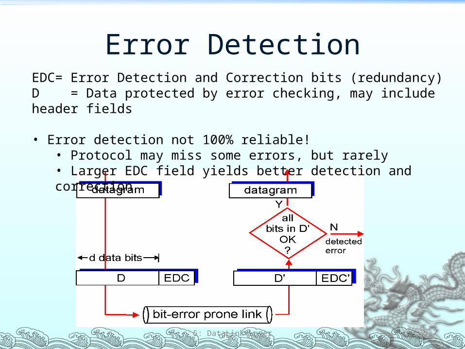
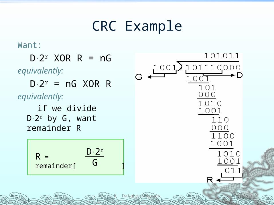
Link Layer 51 Introduction and
services 52 Error detection and
correction 53 Multiple access
protocols 54 Link-Layer Addressing 55 Ethernet
56 Hubs and switches 57 PPP
5 DataLink Layer 5-10
Multiple Access Links and Protocols
Two types of ldquolinksrdquo Point-to-point
PPP for dial-up access Point-to-point link between Ethernet switch and host
Broadcast (shared wire or medium) Old-fashioned Ethernet Upstream HFC 80211 wireless LAN
5 DataLink Layer 5-11
Multiple Access protocols Single shared broadcast channel Two or more simultaneous transmissions by nodes
interference Collision if node receives two or more signals at the same time
Multiple access protocol Distributed algorithm that determines how nodes share
channel ie determine when node can transmit Communication about channel sharing must use channel
itself No out-of-band channel for coordination
5 DataLink Layer 5-12
Ideal Multiple Access Protocol
Broadcast channel of rate R bps1 When one node wants to transmit it can send at rate R
2 When M nodes want to transmit each can send at average rate RM
3 Fully decentralized No special node to coordinate transmissions No synchronization of clocks slots
4 Simple
5 DataLink Layer 5-13
MAC Protocols a Taxonomy
Three broad classes Channel Partitioning TDMA FDMA CDMA (in wireless)
Divide channel into smaller ldquopiecesrdquo (time slots frequency code)
Allocate piece to node for exclusive use
Random Access ALOHA CSMA CSMACD CSMACA Channel not divided allow collisions ldquoRecoverrdquo from collisions
ldquoTaking turnsrdquo Polling Token passing Nodes take turns but nodes with more to send can take longer
turns
5 DataLink Layer 5-14
Random Access Protocols When node has packet to send
Transmit at full channel data rate R No a priori coordination among nodes
Two or more transmitting nodes ldquocollisionrdquo Random access MAC protocol specifies
How to detect collisions How to recover from collisions (eg via delayed retransmissions)
Examples of random access MAC protocols Slotted ALOHA ALOHA CSMA CSMACD CSMACA
5 DataLink Layer 5-15
Slotted ALOHA
Assumptions All frames same size Time is divided into equal
size slots time to transmit 1 frame
Nodes start to transmit frames only at beginning of slots
Nodes are synchronized If 2 or more nodes
transmit in slot all nodes detect collision
Operation When node obtains fresh
frame it transmits in next slot
No collision node can send new frame in next slot
If collision node retransmits frame in each subsequent slot with prob p until success
5 DataLink Layer 5-16
Slotted ALOHA
Pros Single active node can
continuously transmit at full rate of channel
Highly decentralized only slots in nodes need to be in sync
Simple
Cons Collisions wasting slots Idle slots Nodes may be able to
detect collision in less than time to transmit packet
Clock synchronization
5 DataLink Layer 5-17
Pure (Unslotted) ALOHA Unslotted Aloha simpler no synchronization When frame first arrives
Transmit immediately Collision probability increases
Frame sent at t0 collides with other frames sent in [t0-1t0+1]
5 DataLink Layer 5-18
CSMA (Carrier Sense Multiple Access)
CSMA listen before transmitThis is Carrier Sensing
If channel sensed idle transmit entire frame If channel sensed busy defer transmission
Human analogy donrsquot interrupt others
5 DataLink Layer 5-19
If someone else is already transmitting then back off (wait) until channel is free Wait how long
If collision is detected during transmission then must retransmit the frame When is it retransmitted
CSMA (Carrier Sense Multiple Access)
1-Persistent CSMA If channel sensed idle transmit entire pkt If channel sensed busy wait until channel becomes idle and then transmit
right away If collision occurs wait random time and then restart process
Non-persistent CSMA (for nonslotted channels) If channel sensed idle transmit entire pkt If channel sensed busy wait random time before trying again If collision occurs wait random time and then restart process
P-Persistent CSMA (for slotted channels) If channel sensed idle then with probability p transmit in current slot
With probability q=1-p wait until next slot and try again (with probability p)
If channel sensed busy wait until next slot and try again If collision occurs wait random time and then restart process
5 DataLink Layer 5-20
CSMA Collisions
5 DataLink Layer 5-21
Collisions can still occurpropagation delay means two nodes may not heareach otherrsquos transmissionCollisionentire packet transmission time wasted
spatial layout of nodes
Noterole of distance amp propagation delay in determining collision probability
CSMACD (Collision Detection)
CSMACD carrier sensing deferral as in CSMA
Collisions detected within short time Colliding transmissions aborted
reducing channel wastage Collision detection
Easy in wired LANs measure signal strengths compare transmitted received signals
Difficult in wireless LANs receiver shut off while transmitting
5 DataLink Layer 5-22
ldquoTaking Turnsrdquo MAC protocols
Channel partitioning MAC protocols Share channel efficiently and fairly at high load Inefficient at low load delay in channel access 1N
bandwidth allocated even if only 1 active node
Random access MAC protocols Efficient at low load single node can fully utilize channel High load collision overhead
ldquoTaking turnsrdquo protocolsLook for best of both worlds
5 DataLink Layer 5-23
ldquoTaking Turnsrdquo MAC protocols
Polling Master node ldquoinvitesrdquo
slave nodes to transmit in turn
Concerns Polling overhead Latency Single point of failure
(master)
5 DataLink Layer 5-24
Token passing Control token passed from one
node to next sequentially Token message Concerns
Token overhead Latency Single point of failure (token)
Summary of MAC Protocols What do you do with a shared media
Channel Partitioning by time frequency or code Time Division Frequency Division
Random partitioning (dynamic) ALOHA S-ALOHA CSMA CSMACD Carrier sensing easy in some technologies (wire) hard in
others (wireless) CSMACD used in Ethernet CSMACA used in 80211
Taking Turns Polling from a central site token passing
5 DataLink Layer 5-25
LAN TechnologiesData link layer so far
Services error detectioncorrection multiple access
Next LAN technologies Addressing Ethernet Hubs switches IEEE 80211 (wireless) PPP
5 DataLink Layer 5-26
LAN
Router
Link Layer 51 Introduction and
services 52 Error detection and
correction 53 Multiple access
protocols 54 Link-Layer Addressing 55 Ethernet
56 Hubs and switches 57 PPP
5 DataLink Layer 5-27
MAC Addresses and ARP
32-bit IP address Network-layer address Used to get datagram to destination IP subnet
MAC (or LAN or physical or Ethernet) address Used to get frame from one interface to another
physically-connected interface (same network) 48 bit MAC address (for most LANs)
burned in the adapter ROM
5 DataLink Layer 5-28
LAN Addresses and ARP
5 DataLink Layer 5-29
Each adapter on LAN has unique LAN address
Broadcast address =FF-FF-FF-FF-FF-FF
= adapter
1A-2F-BB-76-09-AD
58-23-D7-FA-20-B0
0C-C4-11-6F-E3-98
71-65-F7-2B-08-53
LAN(wired orwireless)
Recall Earlier Routing Discussion
5 DataLink Layer 5-30
223111
223112
223113
223114 223129
223122
223121
223132223131
2231327
A
BE
Starting at A given IP datagram addressed to B
Look up net address of B find B on same net as A
Link layer send datagram to B inside link-layer frame
Brsquos MACaddr
Arsquos MACaddr
Arsquos IPaddr
Brsquos IPaddr
IP payload
datagramframe
frame sourcedest address
datagram sourcedest address
ARP Address Resolution Protocol
Each IP node (Host Router) on LAN has ARP table
ARP Table IPMAC address mappings for some LAN nodes
lt IP address MAC address TTLgt TTL (Time To Live) time
after which address mapping will be forgotten (typically 20 min)
5 DataLink Layer 5-31
Question how to determineMAC address of B knowing Brsquos IP address
1A-2F-BB-76-09-AD
58-23-D7-FA-20-B0
0C-C4-11-6F-E3-98
71-65-F7-2B-08-53
LAN
137196723
137196778
137196714
137196788
ARP Protocol Same LAN (network)
A wants to send datagram to B and Brsquos MAC address not in Arsquos ARP table
A broadcasts ARP query packet containing Bs IP address
Dest MAC address = FF-FF-FF-FF-FF-FF
All machines on LAN receive ARP query
B receives ARP packet replies to A with its (Bs) MAC address
Frame sent to Arsquos MAC address (unicast)
A caches (saves) IP-to-MAC address pair in its ARP table until information becomes old (times out)
Soft state information that times out (goes away) unless refreshed
ARP is ldquoplug-and-playrdquo Nodes create their ARP
tables without intervention from net administrator
5 DataLink Layer 5-32
Link Layer 51 Introduction and
services 52 Error detection and
correction 53 Multiple access
protocols 54 Link-Layer Addressing 55 Ethernet
56 Hubs and switches 57 PPP
5 DataLink Layer 5-33
EthernetldquoDominantrdquo wired LAN technology Cheap $20 for 100Mbs First widely used LAN technology Simpler cheaper than token LANs and ATM Kept up with speed race 10 Mbps ndash 10 Gbps
5 DataLink Layer 5-34
Metcalfersquos Ethernetsketch
Star Topology Bus topology popular through mid 90s Now star topology prevails Connection choices hub or switch (more later)
5 DataLink Layer 5-35
hub orswitch
Ethernet uses CSMACD No slots Adapter doesnrsquot transmit if
it senses that some other adapter is transmitting that is carrier sense
Transmitting adapter aborts when it senses that another adapter is transmitting that is collision detection
Before attempting a retransmission adapter waits a random time that is random access
5 DataLink Layer 5-36
random time depends upon collisions so far
Ethernet CSMACD Algorithm
1 Adaptor receives datagram from network layer amp creates frame
2 If adapter senses channel idle it starts to transmit frame If it senses channel busy waits until channel idle and then transmits
3 If adapter transmits entire frame without detecting another transmission the adapter is done with frame
4 If adapter detects another transmission while transmitting aborts and sends jam signal
5 After aborting adapter enters exponential backoff after the mth collision adapter chooses a K at random from 012hellip2m-1 Adapter waits K512 bit times and returns to Step 2
5 DataLink Layer 5-37
Ethernetrsquos CSMACD (more)Jam Signal make sure all other
transmitters are aware of collision 48 bits
Bit time 1 microsec for 10 Mbps Ethernet for K=1023 wait time is about 50 msec
Exponential Backoff Goal adapt retransmission
attempts to estimated current load
Heavy load random wait will be longer
First collision choose K from 01 delay is K 512 bit transmission times
After second collision choose K from 0123hellip
After ten collisions choose K from 01234hellip1023
5 DataLink Layer 5-38
Link Layer 51 Introduction and
services 52 Error detection and
correction 53Multiple access
protocols 54 Link-Layer Addressing 55 Ethernet
56 Interconnections Hubs and switches
57 PPP
5 DataLink Layer 5-39
Hubs Physical Layer devices essentially repeaters operating
at bit levels repeat received bits on one interface to all other interfaces
Hubs can be arranged in a hierarchy (or multi-tier design) with backbone hub at its top
5 DataLink Layer 5-40
hub
hubhub
hub
Hubs (more)
Each connected LAN referred to as LAN segment Hubs do not isolate collision domains node may
collide with any node residing at any segment in LAN Hub Advantages
Simple inexpensive device Multi-tier provides graceful degradation portions of
the LAN continue to operate if one hub malfunctions Extends maximum distance between node pairs (100m
per Hub)
5 DataLink Layer 5-41
Hub Limitations Single collision domain results in no increase in max
throughput Multi-tier throughput same as single segment
throughput Individual LAN restrictions pose limits on number of nodes
in same collision domain and on total allowed geographical coverage
Cannot connect different Ethernet types (eg 10BaseT and 100baseT)
We now move on to switches
5 DataLink Layer 5-42
Switch Link layer device
Stores and forwards Ethernet frames Examines frame header and selectively forwards frame
based on MAC dest address When frame is to be forwarded on segment uses
CSMACD to access segment Transparent
Hosts are unaware of presence of switches Plug-and-play self-learning
Switches do not need to be configured
5 DataLink Layer 5-43
Switch Traffic Isolation Switch installation breaks subnet into LAN segments Switch filters packets
Same-LAN-segment frames not usually forwarded onto other LAN segments
Segments become separate collision domains
5 DataLink Layer 5-44
hub hub hub
switch
collision domain collision domain
collision domain
Switch Forwarding
5 DataLink Layer 5-45
How do determine onto which LAN segment to forward frame
Looks like a routing problem
hub
hubhub
switch1
2 3
Switch Self Learning A switch has a switch table Entry in switch table
(MAC Address Interface Time Stamp) Stale entries in table dropped (TTL can be 60 min)
Switch learns which hosts can be reached through which interfaces
When frame received switch ldquolearnsrdquo location of sender incoming LAN segment
Records senderlocation pair in switch table
5 DataLink Layer 5-46
Switch FilteringForwarding
When switch receives a frame
Index switch table using MAC dest address
if entry found for destinationthen
if dest on segment from which frame arrived then drop the frame
else forward the frame on interface indicated
else flood
5 DataLink Layer 5-47
forward on all but the interface on which the frame arrived
Switch Example
Suppose C sends frame to D
5 DataLink Layer 5-48
Switch receives frame from from C Notes in switch table that C is on interface 1 Because D is not in table switch forwards frame into interfaces
2 and 3
Frame received by D
hub
hub hub
switch
A
B CD
EF
G H
I
address interface
ABEG
1123
12 3
Switch Example
Suppose D replies back with frame to C
5 DataLink Layer 5-49
Switch receives frame from from D Notes in switch table that D is on interface 2 Because C is in table switch forwards frame only to interface 1
Frame received by C
hub
hub hub
switch
A
B CD
EF
G H
I
address interface
ABEGC
11231
Institutional Network
5 DataLink Layer 5-50
hub
hubhub
switch
to externalnetwork
router
IP subnet
mail server
web server
Chapter 5 Summary Principles behind data link layer services
Error detection correction Sharing a broadcast channel multiple access Link layer addressing
Instantiation and implementation of various link layer technologies
Ethernet Hubs switches IEEE 80211 (detailed see next Chapter) PPP
5 DataLink Layer 5-51
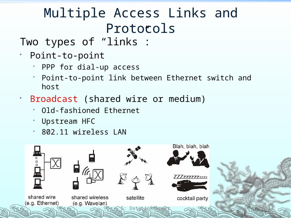
Slotted ALOHA
Assumptions All frames same size Time is divided into equal
size slots time to transmit 1 frame
Nodes start to transmit frames only at beginning of slots
Nodes are synchronized If 2 or more nodes
transmit in slot all nodes detect collision
Operation When node obtains fresh
frame it transmits in next slot
No collision node can send new frame in next slot
If collision node retransmits frame in each subsequent slot with prob p until success
5 DataLink Layer 5-16
Slotted ALOHA
Pros Single active node can
continuously transmit at full rate of channel
Highly decentralized only slots in nodes need to be in sync
Simple
Cons Collisions wasting slots Idle slots Nodes may be able to
detect collision in less than time to transmit packet
Clock synchronization
5 DataLink Layer 5-17
Pure (Unslotted) ALOHA Unslotted Aloha simpler no synchronization When frame first arrives
Transmit immediately Collision probability increases
Frame sent at t0 collides with other frames sent in [t0-1t0+1]
5 DataLink Layer 5-18
CSMA (Carrier Sense Multiple Access)
CSMA listen before transmitThis is Carrier Sensing
If channel sensed idle transmit entire frame If channel sensed busy defer transmission
Human analogy donrsquot interrupt others
5 DataLink Layer 5-19
If someone else is already transmitting then back off (wait) until channel is free Wait how long
If collision is detected during transmission then must retransmit the frame When is it retransmitted
CSMA (Carrier Sense Multiple Access)
1-Persistent CSMA If channel sensed idle transmit entire pkt If channel sensed busy wait until channel becomes idle and then transmit
right away If collision occurs wait random time and then restart process
Non-persistent CSMA (for nonslotted channels) If channel sensed idle transmit entire pkt If channel sensed busy wait random time before trying again If collision occurs wait random time and then restart process
P-Persistent CSMA (for slotted channels) If channel sensed idle then with probability p transmit in current slot
With probability q=1-p wait until next slot and try again (with probability p)
If channel sensed busy wait until next slot and try again If collision occurs wait random time and then restart process
5 DataLink Layer 5-20
CSMA Collisions
5 DataLink Layer 5-21
Collisions can still occurpropagation delay means two nodes may not heareach otherrsquos transmissionCollisionentire packet transmission time wasted
spatial layout of nodes
Noterole of distance amp propagation delay in determining collision probability
CSMACD (Collision Detection)
CSMACD carrier sensing deferral as in CSMA
Collisions detected within short time Colliding transmissions aborted
reducing channel wastage Collision detection
Easy in wired LANs measure signal strengths compare transmitted received signals
Difficult in wireless LANs receiver shut off while transmitting
5 DataLink Layer 5-22
ldquoTaking Turnsrdquo MAC protocols
Channel partitioning MAC protocols Share channel efficiently and fairly at high load Inefficient at low load delay in channel access 1N
bandwidth allocated even if only 1 active node
Random access MAC protocols Efficient at low load single node can fully utilize channel High load collision overhead
ldquoTaking turnsrdquo protocolsLook for best of both worlds
5 DataLink Layer 5-23
ldquoTaking Turnsrdquo MAC protocols
Polling Master node ldquoinvitesrdquo
slave nodes to transmit in turn
Concerns Polling overhead Latency Single point of failure
(master)
5 DataLink Layer 5-24
Token passing Control token passed from one
node to next sequentially Token message Concerns
Token overhead Latency Single point of failure (token)
Summary of MAC Protocols What do you do with a shared media
Channel Partitioning by time frequency or code Time Division Frequency Division
Random partitioning (dynamic) ALOHA S-ALOHA CSMA CSMACD Carrier sensing easy in some technologies (wire) hard in
others (wireless) CSMACD used in Ethernet CSMACA used in 80211
Taking Turns Polling from a central site token passing
5 DataLink Layer 5-25
LAN TechnologiesData link layer so far
Services error detectioncorrection multiple access
Next LAN technologies Addressing Ethernet Hubs switches IEEE 80211 (wireless) PPP
5 DataLink Layer 5-26
LAN
Router
Link Layer 51 Introduction and
services 52 Error detection and
correction 53 Multiple access
protocols 54 Link-Layer Addressing 55 Ethernet
56 Hubs and switches 57 PPP
5 DataLink Layer 5-27
MAC Addresses and ARP
32-bit IP address Network-layer address Used to get datagram to destination IP subnet
MAC (or LAN or physical or Ethernet) address Used to get frame from one interface to another
physically-connected interface (same network) 48 bit MAC address (for most LANs)
burned in the adapter ROM
5 DataLink Layer 5-28
LAN Addresses and ARP
5 DataLink Layer 5-29
Each adapter on LAN has unique LAN address
Broadcast address =FF-FF-FF-FF-FF-FF
= adapter
1A-2F-BB-76-09-AD
58-23-D7-FA-20-B0
0C-C4-11-6F-E3-98
71-65-F7-2B-08-53
LAN(wired orwireless)
Recall Earlier Routing Discussion
5 DataLink Layer 5-30
223111
223112
223113
223114 223129
223122
223121
223132223131
2231327
A
BE
Starting at A given IP datagram addressed to B
Look up net address of B find B on same net as A
Link layer send datagram to B inside link-layer frame
Brsquos MACaddr
Arsquos MACaddr
Arsquos IPaddr
Brsquos IPaddr
IP payload
datagramframe
frame sourcedest address
datagram sourcedest address
ARP Address Resolution Protocol
Each IP node (Host Router) on LAN has ARP table
ARP Table IPMAC address mappings for some LAN nodes
lt IP address MAC address TTLgt TTL (Time To Live) time
after which address mapping will be forgotten (typically 20 min)
5 DataLink Layer 5-31
Question how to determineMAC address of B knowing Brsquos IP address
1A-2F-BB-76-09-AD
58-23-D7-FA-20-B0
0C-C4-11-6F-E3-98
71-65-F7-2B-08-53
LAN
137196723
137196778
137196714
137196788
ARP Protocol Same LAN (network)
A wants to send datagram to B and Brsquos MAC address not in Arsquos ARP table
A broadcasts ARP query packet containing Bs IP address
Dest MAC address = FF-FF-FF-FF-FF-FF
All machines on LAN receive ARP query
B receives ARP packet replies to A with its (Bs) MAC address
Frame sent to Arsquos MAC address (unicast)
A caches (saves) IP-to-MAC address pair in its ARP table until information becomes old (times out)
Soft state information that times out (goes away) unless refreshed
ARP is ldquoplug-and-playrdquo Nodes create their ARP
tables without intervention from net administrator
5 DataLink Layer 5-32
Link Layer 51 Introduction and
services 52 Error detection and
correction 53 Multiple access
protocols 54 Link-Layer Addressing 55 Ethernet
56 Hubs and switches 57 PPP
5 DataLink Layer 5-33
EthernetldquoDominantrdquo wired LAN technology Cheap $20 for 100Mbs First widely used LAN technology Simpler cheaper than token LANs and ATM Kept up with speed race 10 Mbps ndash 10 Gbps
5 DataLink Layer 5-34
Metcalfersquos Ethernetsketch
Star Topology Bus topology popular through mid 90s Now star topology prevails Connection choices hub or switch (more later)
5 DataLink Layer 5-35
hub orswitch
Ethernet uses CSMACD No slots Adapter doesnrsquot transmit if
it senses that some other adapter is transmitting that is carrier sense
Transmitting adapter aborts when it senses that another adapter is transmitting that is collision detection
Before attempting a retransmission adapter waits a random time that is random access
5 DataLink Layer 5-36
random time depends upon collisions so far
Ethernet CSMACD Algorithm
1 Adaptor receives datagram from network layer amp creates frame
2 If adapter senses channel idle it starts to transmit frame If it senses channel busy waits until channel idle and then transmits
3 If adapter transmits entire frame without detecting another transmission the adapter is done with frame
4 If adapter detects another transmission while transmitting aborts and sends jam signal
5 After aborting adapter enters exponential backoff after the mth collision adapter chooses a K at random from 012hellip2m-1 Adapter waits K512 bit times and returns to Step 2
5 DataLink Layer 5-37
Ethernetrsquos CSMACD (more)Jam Signal make sure all other
transmitters are aware of collision 48 bits
Bit time 1 microsec for 10 Mbps Ethernet for K=1023 wait time is about 50 msec
Exponential Backoff Goal adapt retransmission
attempts to estimated current load
Heavy load random wait will be longer
First collision choose K from 01 delay is K 512 bit transmission times
After second collision choose K from 0123hellip
After ten collisions choose K from 01234hellip1023
5 DataLink Layer 5-38
Link Layer 51 Introduction and
services 52 Error detection and
correction 53Multiple access
protocols 54 Link-Layer Addressing 55 Ethernet
56 Interconnections Hubs and switches
57 PPP
5 DataLink Layer 5-39
Hubs Physical Layer devices essentially repeaters operating
at bit levels repeat received bits on one interface to all other interfaces
Hubs can be arranged in a hierarchy (or multi-tier design) with backbone hub at its top
5 DataLink Layer 5-40
hub
hubhub
hub
Hubs (more)
Each connected LAN referred to as LAN segment Hubs do not isolate collision domains node may
collide with any node residing at any segment in LAN Hub Advantages
Simple inexpensive device Multi-tier provides graceful degradation portions of
the LAN continue to operate if one hub malfunctions Extends maximum distance between node pairs (100m
per Hub)
5 DataLink Layer 5-41
Hub Limitations Single collision domain results in no increase in max
throughput Multi-tier throughput same as single segment
throughput Individual LAN restrictions pose limits on number of nodes
in same collision domain and on total allowed geographical coverage
Cannot connect different Ethernet types (eg 10BaseT and 100baseT)
We now move on to switches
5 DataLink Layer 5-42
Switch Link layer device
Stores and forwards Ethernet frames Examines frame header and selectively forwards frame
based on MAC dest address When frame is to be forwarded on segment uses
CSMACD to access segment Transparent
Hosts are unaware of presence of switches Plug-and-play self-learning
Switches do not need to be configured
5 DataLink Layer 5-43
Switch Traffic Isolation Switch installation breaks subnet into LAN segments Switch filters packets
Same-LAN-segment frames not usually forwarded onto other LAN segments
Segments become separate collision domains
5 DataLink Layer 5-44
hub hub hub
switch
collision domain collision domain
collision domain
Switch Forwarding
5 DataLink Layer 5-45
How do determine onto which LAN segment to forward frame
Looks like a routing problem
hub
hubhub
switch1
2 3
Switch Self Learning A switch has a switch table Entry in switch table
(MAC Address Interface Time Stamp) Stale entries in table dropped (TTL can be 60 min)
Switch learns which hosts can be reached through which interfaces
When frame received switch ldquolearnsrdquo location of sender incoming LAN segment
Records senderlocation pair in switch table
5 DataLink Layer 5-46
Switch FilteringForwarding
When switch receives a frame
Index switch table using MAC dest address
if entry found for destinationthen
if dest on segment from which frame arrived then drop the frame
else forward the frame on interface indicated
else flood
5 DataLink Layer 5-47
forward on all but the interface on which the frame arrived
Switch Example
Suppose C sends frame to D
5 DataLink Layer 5-48
Switch receives frame from from C Notes in switch table that C is on interface 1 Because D is not in table switch forwards frame into interfaces
2 and 3
Frame received by D
hub
hub hub
switch
A
B CD
EF
G H
I
address interface
ABEG
1123
12 3
Switch Example
Suppose D replies back with frame to C
5 DataLink Layer 5-49
Switch receives frame from from D Notes in switch table that D is on interface 2 Because C is in table switch forwards frame only to interface 1
Frame received by C
hub
hub hub
switch
A
B CD
EF
G H
I
address interface
ABEGC
11231
Institutional Network
5 DataLink Layer 5-50
hub
hubhub
switch
to externalnetwork
router
IP subnet
mail server
web server
Chapter 5 Summary Principles behind data link layer services
Error detection correction Sharing a broadcast channel multiple access Link layer addressing
Instantiation and implementation of various link layer technologies
Ethernet Hubs switches IEEE 80211 (detailed see next Chapter) PPP
5 DataLink Layer 5-51
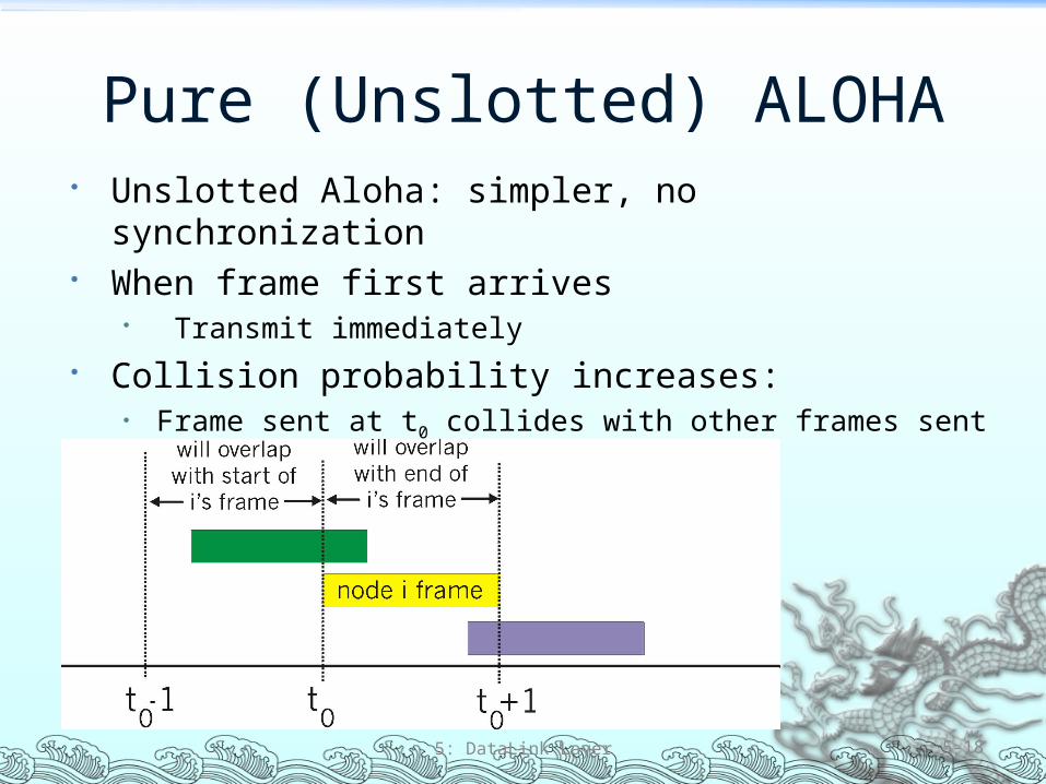
CSMA (Carrier Sense Multiple Access)
CSMA listen before transmitThis is Carrier Sensing
If channel sensed idle transmit entire frame If channel sensed busy defer transmission
Human analogy donrsquot interrupt others
5 DataLink Layer 5-19
If someone else is already transmitting then back off (wait) until channel is free Wait how long
If collision is detected during transmission then must retransmit the frame When is it retransmitted
CSMA (Carrier Sense Multiple Access)
1-Persistent CSMA If channel sensed idle transmit entire pkt If channel sensed busy wait until channel becomes idle and then transmit
right away If collision occurs wait random time and then restart process
Non-persistent CSMA (for nonslotted channels) If channel sensed idle transmit entire pkt If channel sensed busy wait random time before trying again If collision occurs wait random time and then restart process
P-Persistent CSMA (for slotted channels) If channel sensed idle then with probability p transmit in current slot
With probability q=1-p wait until next slot and try again (with probability p)
If channel sensed busy wait until next slot and try again If collision occurs wait random time and then restart process
5 DataLink Layer 5-20
CSMA Collisions
5 DataLink Layer 5-21
Collisions can still occurpropagation delay means two nodes may not heareach otherrsquos transmissionCollisionentire packet transmission time wasted
spatial layout of nodes
Noterole of distance amp propagation delay in determining collision probability
CSMACD (Collision Detection)
CSMACD carrier sensing deferral as in CSMA
Collisions detected within short time Colliding transmissions aborted
reducing channel wastage Collision detection
Easy in wired LANs measure signal strengths compare transmitted received signals
Difficult in wireless LANs receiver shut off while transmitting
5 DataLink Layer 5-22
ldquoTaking Turnsrdquo MAC protocols
Channel partitioning MAC protocols Share channel efficiently and fairly at high load Inefficient at low load delay in channel access 1N
bandwidth allocated even if only 1 active node
Random access MAC protocols Efficient at low load single node can fully utilize channel High load collision overhead
ldquoTaking turnsrdquo protocolsLook for best of both worlds
5 DataLink Layer 5-23
ldquoTaking Turnsrdquo MAC protocols
Polling Master node ldquoinvitesrdquo
slave nodes to transmit in turn
Concerns Polling overhead Latency Single point of failure
(master)
5 DataLink Layer 5-24
Token passing Control token passed from one
node to next sequentially Token message Concerns
Token overhead Latency Single point of failure (token)
Summary of MAC Protocols What do you do with a shared media
Channel Partitioning by time frequency or code Time Division Frequency Division
Random partitioning (dynamic) ALOHA S-ALOHA CSMA CSMACD Carrier sensing easy in some technologies (wire) hard in
others (wireless) CSMACD used in Ethernet CSMACA used in 80211
Taking Turns Polling from a central site token passing
5 DataLink Layer 5-25
LAN TechnologiesData link layer so far
Services error detectioncorrection multiple access
Next LAN technologies Addressing Ethernet Hubs switches IEEE 80211 (wireless) PPP
5 DataLink Layer 5-26
LAN
Router
Link Layer 51 Introduction and
services 52 Error detection and
correction 53 Multiple access
protocols 54 Link-Layer Addressing 55 Ethernet
56 Hubs and switches 57 PPP
5 DataLink Layer 5-27
MAC Addresses and ARP
32-bit IP address Network-layer address Used to get datagram to destination IP subnet
MAC (or LAN or physical or Ethernet) address Used to get frame from one interface to another
physically-connected interface (same network) 48 bit MAC address (for most LANs)
burned in the adapter ROM
5 DataLink Layer 5-28
LAN Addresses and ARP
5 DataLink Layer 5-29
Each adapter on LAN has unique LAN address
Broadcast address =FF-FF-FF-FF-FF-FF
= adapter
1A-2F-BB-76-09-AD
58-23-D7-FA-20-B0
0C-C4-11-6F-E3-98
71-65-F7-2B-08-53
LAN(wired orwireless)
Recall Earlier Routing Discussion
5 DataLink Layer 5-30
223111
223112
223113
223114 223129
223122
223121
223132223131
2231327
A
BE
Starting at A given IP datagram addressed to B
Look up net address of B find B on same net as A
Link layer send datagram to B inside link-layer frame
Brsquos MACaddr
Arsquos MACaddr
Arsquos IPaddr
Brsquos IPaddr
IP payload
datagramframe
frame sourcedest address
datagram sourcedest address
ARP Address Resolution Protocol
Each IP node (Host Router) on LAN has ARP table
ARP Table IPMAC address mappings for some LAN nodes
lt IP address MAC address TTLgt TTL (Time To Live) time
after which address mapping will be forgotten (typically 20 min)
5 DataLink Layer 5-31
Question how to determineMAC address of B knowing Brsquos IP address
1A-2F-BB-76-09-AD
58-23-D7-FA-20-B0
0C-C4-11-6F-E3-98
71-65-F7-2B-08-53
LAN
137196723
137196778
137196714
137196788
ARP Protocol Same LAN (network)
A wants to send datagram to B and Brsquos MAC address not in Arsquos ARP table
A broadcasts ARP query packet containing Bs IP address
Dest MAC address = FF-FF-FF-FF-FF-FF
All machines on LAN receive ARP query
B receives ARP packet replies to A with its (Bs) MAC address
Frame sent to Arsquos MAC address (unicast)
A caches (saves) IP-to-MAC address pair in its ARP table until information becomes old (times out)
Soft state information that times out (goes away) unless refreshed
ARP is ldquoplug-and-playrdquo Nodes create their ARP
tables without intervention from net administrator
5 DataLink Layer 5-32
Link Layer 51 Introduction and
services 52 Error detection and
correction 53 Multiple access
protocols 54 Link-Layer Addressing 55 Ethernet
56 Hubs and switches 57 PPP
5 DataLink Layer 5-33
EthernetldquoDominantrdquo wired LAN technology Cheap $20 for 100Mbs First widely used LAN technology Simpler cheaper than token LANs and ATM Kept up with speed race 10 Mbps ndash 10 Gbps
5 DataLink Layer 5-34
Metcalfersquos Ethernetsketch
Star Topology Bus topology popular through mid 90s Now star topology prevails Connection choices hub or switch (more later)
5 DataLink Layer 5-35
hub orswitch
Ethernet uses CSMACD No slots Adapter doesnrsquot transmit if
it senses that some other adapter is transmitting that is carrier sense
Transmitting adapter aborts when it senses that another adapter is transmitting that is collision detection
Before attempting a retransmission adapter waits a random time that is random access
5 DataLink Layer 5-36
random time depends upon collisions so far
Ethernet CSMACD Algorithm
1 Adaptor receives datagram from network layer amp creates frame
2 If adapter senses channel idle it starts to transmit frame If it senses channel busy waits until channel idle and then transmits
3 If adapter transmits entire frame without detecting another transmission the adapter is done with frame
4 If adapter detects another transmission while transmitting aborts and sends jam signal
5 After aborting adapter enters exponential backoff after the mth collision adapter chooses a K at random from 012hellip2m-1 Adapter waits K512 bit times and returns to Step 2
5 DataLink Layer 5-37
Ethernetrsquos CSMACD (more)Jam Signal make sure all other
transmitters are aware of collision 48 bits
Bit time 1 microsec for 10 Mbps Ethernet for K=1023 wait time is about 50 msec
Exponential Backoff Goal adapt retransmission
attempts to estimated current load
Heavy load random wait will be longer
First collision choose K from 01 delay is K 512 bit transmission times
After second collision choose K from 0123hellip
After ten collisions choose K from 01234hellip1023
5 DataLink Layer 5-38
Link Layer 51 Introduction and
services 52 Error detection and
correction 53Multiple access
protocols 54 Link-Layer Addressing 55 Ethernet
56 Interconnections Hubs and switches
57 PPP
5 DataLink Layer 5-39
Hubs Physical Layer devices essentially repeaters operating
at bit levels repeat received bits on one interface to all other interfaces
Hubs can be arranged in a hierarchy (or multi-tier design) with backbone hub at its top
5 DataLink Layer 5-40
hub
hubhub
hub
Hubs (more)
Each connected LAN referred to as LAN segment Hubs do not isolate collision domains node may
collide with any node residing at any segment in LAN Hub Advantages
Simple inexpensive device Multi-tier provides graceful degradation portions of
the LAN continue to operate if one hub malfunctions Extends maximum distance between node pairs (100m
per Hub)
5 DataLink Layer 5-41
Hub Limitations Single collision domain results in no increase in max
throughput Multi-tier throughput same as single segment
throughput Individual LAN restrictions pose limits on number of nodes
in same collision domain and on total allowed geographical coverage
Cannot connect different Ethernet types (eg 10BaseT and 100baseT)
We now move on to switches
5 DataLink Layer 5-42
Switch Link layer device
Stores and forwards Ethernet frames Examines frame header and selectively forwards frame
based on MAC dest address When frame is to be forwarded on segment uses
CSMACD to access segment Transparent
Hosts are unaware of presence of switches Plug-and-play self-learning
Switches do not need to be configured
5 DataLink Layer 5-43
Switch Traffic Isolation Switch installation breaks subnet into LAN segments Switch filters packets
Same-LAN-segment frames not usually forwarded onto other LAN segments
Segments become separate collision domains
5 DataLink Layer 5-44
hub hub hub
switch
collision domain collision domain
collision domain
Switch Forwarding
5 DataLink Layer 5-45
How do determine onto which LAN segment to forward frame
Looks like a routing problem
hub
hubhub
switch1
2 3
Switch Self Learning A switch has a switch table Entry in switch table
(MAC Address Interface Time Stamp) Stale entries in table dropped (TTL can be 60 min)
Switch learns which hosts can be reached through which interfaces
When frame received switch ldquolearnsrdquo location of sender incoming LAN segment
Records senderlocation pair in switch table
5 DataLink Layer 5-46
Switch FilteringForwarding
When switch receives a frame
Index switch table using MAC dest address
if entry found for destinationthen
if dest on segment from which frame arrived then drop the frame
else forward the frame on interface indicated
else flood
5 DataLink Layer 5-47
forward on all but the interface on which the frame arrived
Switch Example
Suppose C sends frame to D
5 DataLink Layer 5-48
Switch receives frame from from C Notes in switch table that C is on interface 1 Because D is not in table switch forwards frame into interfaces
2 and 3
Frame received by D
hub
hub hub
switch
A
B CD
EF
G H
I
address interface
ABEG
1123
12 3
Switch Example
Suppose D replies back with frame to C
5 DataLink Layer 5-49
Switch receives frame from from D Notes in switch table that D is on interface 2 Because C is in table switch forwards frame only to interface 1
Frame received by C
hub
hub hub
switch
A
B CD
EF
G H
I
address interface
ABEGC
11231
Institutional Network
5 DataLink Layer 5-50
hub
hubhub
switch
to externalnetwork
router
IP subnet
mail server
web server
Chapter 5 Summary Principles behind data link layer services
Error detection correction Sharing a broadcast channel multiple access Link layer addressing
Instantiation and implementation of various link layer technologies
Ethernet Hubs switches IEEE 80211 (detailed see next Chapter) PPP
5 DataLink Layer 5-51
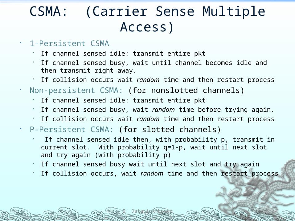
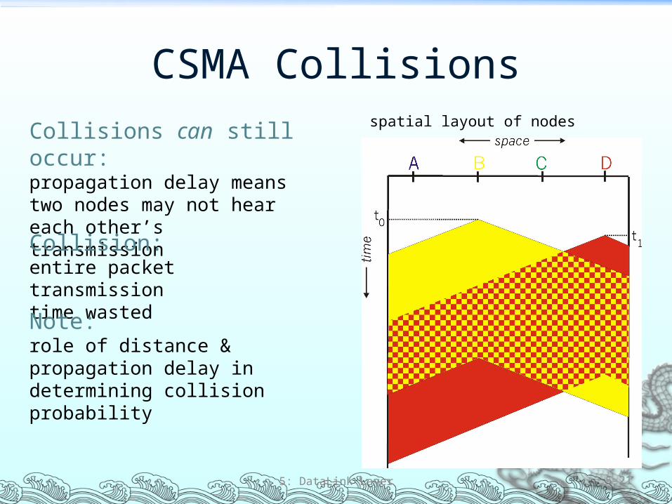
ldquoTaking Turnsrdquo MAC protocols
Channel partitioning MAC protocols Share channel efficiently and fairly at high load Inefficient at low load delay in channel access 1N
bandwidth allocated even if only 1 active node
Random access MAC protocols Efficient at low load single node can fully utilize channel High load collision overhead
ldquoTaking turnsrdquo protocolsLook for best of both worlds
5 DataLink Layer 5-23
ldquoTaking Turnsrdquo MAC protocols
Polling Master node ldquoinvitesrdquo
slave nodes to transmit in turn
Concerns Polling overhead Latency Single point of failure
(master)
5 DataLink Layer 5-24
Token passing Control token passed from one
node to next sequentially Token message Concerns
Token overhead Latency Single point of failure (token)
Summary of MAC Protocols What do you do with a shared media
Channel Partitioning by time frequency or code Time Division Frequency Division
Random partitioning (dynamic) ALOHA S-ALOHA CSMA CSMACD Carrier sensing easy in some technologies (wire) hard in
others (wireless) CSMACD used in Ethernet CSMACA used in 80211
Taking Turns Polling from a central site token passing
5 DataLink Layer 5-25
LAN TechnologiesData link layer so far
Services error detectioncorrection multiple access
Next LAN technologies Addressing Ethernet Hubs switches IEEE 80211 (wireless) PPP
5 DataLink Layer 5-26
LAN
Router
Link Layer 51 Introduction and
services 52 Error detection and
correction 53 Multiple access
protocols 54 Link-Layer Addressing 55 Ethernet
56 Hubs and switches 57 PPP
5 DataLink Layer 5-27
MAC Addresses and ARP
32-bit IP address Network-layer address Used to get datagram to destination IP subnet
MAC (or LAN or physical or Ethernet) address Used to get frame from one interface to another
physically-connected interface (same network) 48 bit MAC address (for most LANs)
burned in the adapter ROM
5 DataLink Layer 5-28
LAN Addresses and ARP
5 DataLink Layer 5-29
Each adapter on LAN has unique LAN address
Broadcast address =FF-FF-FF-FF-FF-FF
= adapter
1A-2F-BB-76-09-AD
58-23-D7-FA-20-B0
0C-C4-11-6F-E3-98
71-65-F7-2B-08-53
LAN(wired orwireless)
Recall Earlier Routing Discussion
5 DataLink Layer 5-30
223111
223112
223113
223114 223129
223122
223121
223132223131
2231327
A
BE
Starting at A given IP datagram addressed to B
Look up net address of B find B on same net as A
Link layer send datagram to B inside link-layer frame
Brsquos MACaddr
Arsquos MACaddr
Arsquos IPaddr
Brsquos IPaddr
IP payload
datagramframe
frame sourcedest address
datagram sourcedest address
ARP Address Resolution Protocol
Each IP node (Host Router) on LAN has ARP table
ARP Table IPMAC address mappings for some LAN nodes
lt IP address MAC address TTLgt TTL (Time To Live) time
after which address mapping will be forgotten (typically 20 min)
5 DataLink Layer 5-31
Question how to determineMAC address of B knowing Brsquos IP address
1A-2F-BB-76-09-AD
58-23-D7-FA-20-B0
0C-C4-11-6F-E3-98
71-65-F7-2B-08-53
LAN
137196723
137196778
137196714
137196788
ARP Protocol Same LAN (network)
A wants to send datagram to B and Brsquos MAC address not in Arsquos ARP table
A broadcasts ARP query packet containing Bs IP address
Dest MAC address = FF-FF-FF-FF-FF-FF
All machines on LAN receive ARP query
B receives ARP packet replies to A with its (Bs) MAC address
Frame sent to Arsquos MAC address (unicast)
A caches (saves) IP-to-MAC address pair in its ARP table until information becomes old (times out)
Soft state information that times out (goes away) unless refreshed
ARP is ldquoplug-and-playrdquo Nodes create their ARP
tables without intervention from net administrator
5 DataLink Layer 5-32
Link Layer 51 Introduction and
services 52 Error detection and
correction 53 Multiple access
protocols 54 Link-Layer Addressing 55 Ethernet
56 Hubs and switches 57 PPP
5 DataLink Layer 5-33
EthernetldquoDominantrdquo wired LAN technology Cheap $20 for 100Mbs First widely used LAN technology Simpler cheaper than token LANs and ATM Kept up with speed race 10 Mbps ndash 10 Gbps
5 DataLink Layer 5-34
Metcalfersquos Ethernetsketch
Star Topology Bus topology popular through mid 90s Now star topology prevails Connection choices hub or switch (more later)
5 DataLink Layer 5-35
hub orswitch
Ethernet uses CSMACD No slots Adapter doesnrsquot transmit if
it senses that some other adapter is transmitting that is carrier sense
Transmitting adapter aborts when it senses that another adapter is transmitting that is collision detection
Before attempting a retransmission adapter waits a random time that is random access
5 DataLink Layer 5-36
random time depends upon collisions so far
Ethernet CSMACD Algorithm
1 Adaptor receives datagram from network layer amp creates frame
2 If adapter senses channel idle it starts to transmit frame If it senses channel busy waits until channel idle and then transmits
3 If adapter transmits entire frame without detecting another transmission the adapter is done with frame
4 If adapter detects another transmission while transmitting aborts and sends jam signal
5 After aborting adapter enters exponential backoff after the mth collision adapter chooses a K at random from 012hellip2m-1 Adapter waits K512 bit times and returns to Step 2
5 DataLink Layer 5-37
Ethernetrsquos CSMACD (more)Jam Signal make sure all other
transmitters are aware of collision 48 bits
Bit time 1 microsec for 10 Mbps Ethernet for K=1023 wait time is about 50 msec
Exponential Backoff Goal adapt retransmission
attempts to estimated current load
Heavy load random wait will be longer
First collision choose K from 01 delay is K 512 bit transmission times
After second collision choose K from 0123hellip
After ten collisions choose K from 01234hellip1023
5 DataLink Layer 5-38
Link Layer 51 Introduction and
services 52 Error detection and
correction 53Multiple access
protocols 54 Link-Layer Addressing 55 Ethernet
56 Interconnections Hubs and switches
57 PPP
5 DataLink Layer 5-39
Hubs Physical Layer devices essentially repeaters operating
at bit levels repeat received bits on one interface to all other interfaces
Hubs can be arranged in a hierarchy (or multi-tier design) with backbone hub at its top
5 DataLink Layer 5-40
hub
hubhub
hub
Hubs (more)
Each connected LAN referred to as LAN segment Hubs do not isolate collision domains node may
collide with any node residing at any segment in LAN Hub Advantages
Simple inexpensive device Multi-tier provides graceful degradation portions of
the LAN continue to operate if one hub malfunctions Extends maximum distance between node pairs (100m
per Hub)
5 DataLink Layer 5-41
Hub Limitations Single collision domain results in no increase in max
throughput Multi-tier throughput same as single segment
throughput Individual LAN restrictions pose limits on number of nodes
in same collision domain and on total allowed geographical coverage
Cannot connect different Ethernet types (eg 10BaseT and 100baseT)
We now move on to switches
5 DataLink Layer 5-42
Switch Link layer device
Stores and forwards Ethernet frames Examines frame header and selectively forwards frame
based on MAC dest address When frame is to be forwarded on segment uses
CSMACD to access segment Transparent
Hosts are unaware of presence of switches Plug-and-play self-learning
Switches do not need to be configured
5 DataLink Layer 5-43
Switch Traffic Isolation Switch installation breaks subnet into LAN segments Switch filters packets
Same-LAN-segment frames not usually forwarded onto other LAN segments
Segments become separate collision domains
5 DataLink Layer 5-44
hub hub hub
switch
collision domain collision domain
collision domain
Switch Forwarding
5 DataLink Layer 5-45
How do determine onto which LAN segment to forward frame
Looks like a routing problem
hub
hubhub
switch1
2 3
Switch Self Learning A switch has a switch table Entry in switch table
(MAC Address Interface Time Stamp) Stale entries in table dropped (TTL can be 60 min)
Switch learns which hosts can be reached through which interfaces
When frame received switch ldquolearnsrdquo location of sender incoming LAN segment
Records senderlocation pair in switch table
5 DataLink Layer 5-46
Switch FilteringForwarding
When switch receives a frame
Index switch table using MAC dest address
if entry found for destinationthen
if dest on segment from which frame arrived then drop the frame
else forward the frame on interface indicated
else flood
5 DataLink Layer 5-47
forward on all but the interface on which the frame arrived
Switch Example
Suppose C sends frame to D
5 DataLink Layer 5-48
Switch receives frame from from C Notes in switch table that C is on interface 1 Because D is not in table switch forwards frame into interfaces
2 and 3
Frame received by D
hub
hub hub
switch
A
B CD
EF
G H
I
address interface
ABEG
1123
12 3
Switch Example
Suppose D replies back with frame to C
5 DataLink Layer 5-49
Switch receives frame from from D Notes in switch table that D is on interface 2 Because C is in table switch forwards frame only to interface 1
Frame received by C
hub
hub hub
switch
A
B CD
EF
G H
I
address interface
ABEGC
11231
Institutional Network
5 DataLink Layer 5-50
hub
hubhub
switch
to externalnetwork
router
IP subnet
mail server
web server
Chapter 5 Summary Principles behind data link layer services
Error detection correction Sharing a broadcast channel multiple access Link layer addressing
Instantiation and implementation of various link layer technologies
Ethernet Hubs switches IEEE 80211 (detailed see next Chapter) PPP
5 DataLink Layer 5-51
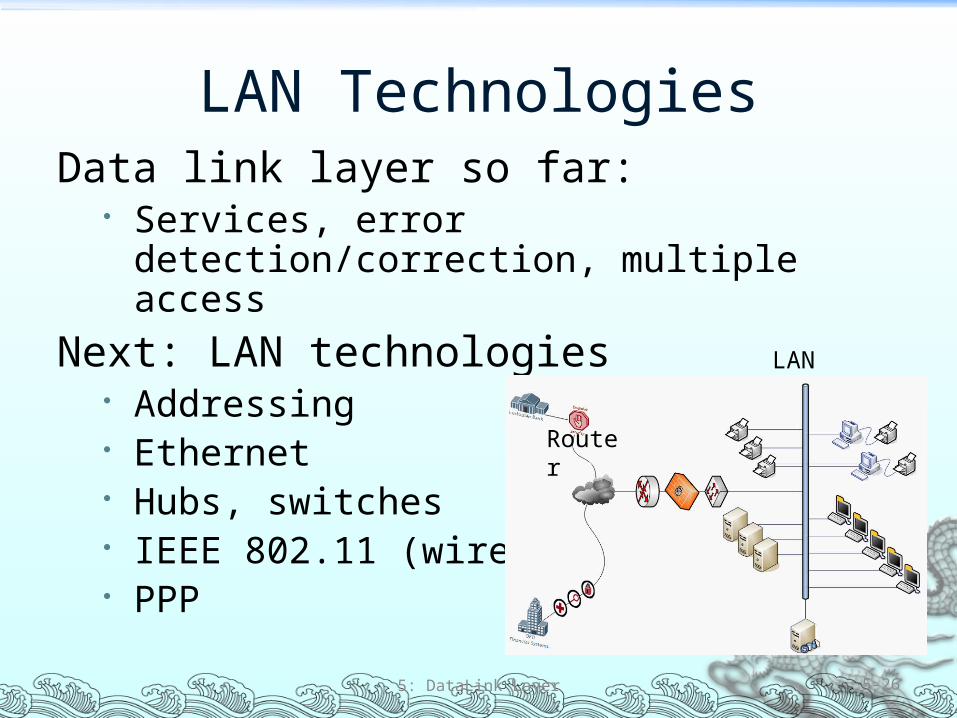
Link Layer 51 Introduction and
services 52 Error detection and
correction 53 Multiple access
protocols 54 Link-Layer Addressing 55 Ethernet
56 Hubs and switches 57 PPP
5 DataLink Layer 5-27
MAC Addresses and ARP
32-bit IP address Network-layer address Used to get datagram to destination IP subnet
MAC (or LAN or physical or Ethernet) address Used to get frame from one interface to another
physically-connected interface (same network) 48 bit MAC address (for most LANs)
burned in the adapter ROM
5 DataLink Layer 5-28
LAN Addresses and ARP
5 DataLink Layer 5-29
Each adapter on LAN has unique LAN address
Broadcast address =FF-FF-FF-FF-FF-FF
= adapter
1A-2F-BB-76-09-AD
58-23-D7-FA-20-B0
0C-C4-11-6F-E3-98
71-65-F7-2B-08-53
LAN(wired orwireless)
Recall Earlier Routing Discussion
5 DataLink Layer 5-30
223111
223112
223113
223114 223129
223122
223121
223132223131
2231327
A
BE
Starting at A given IP datagram addressed to B
Look up net address of B find B on same net as A
Link layer send datagram to B inside link-layer frame
Brsquos MACaddr
Arsquos MACaddr
Arsquos IPaddr
Brsquos IPaddr
IP payload
datagramframe
frame sourcedest address
datagram sourcedest address
ARP Address Resolution Protocol
Each IP node (Host Router) on LAN has ARP table
ARP Table IPMAC address mappings for some LAN nodes
lt IP address MAC address TTLgt TTL (Time To Live) time
after which address mapping will be forgotten (typically 20 min)
5 DataLink Layer 5-31
Question how to determineMAC address of B knowing Brsquos IP address
1A-2F-BB-76-09-AD
58-23-D7-FA-20-B0
0C-C4-11-6F-E3-98
71-65-F7-2B-08-53
LAN
137196723
137196778
137196714
137196788
ARP Protocol Same LAN (network)
A wants to send datagram to B and Brsquos MAC address not in Arsquos ARP table
A broadcasts ARP query packet containing Bs IP address
Dest MAC address = FF-FF-FF-FF-FF-FF
All machines on LAN receive ARP query
B receives ARP packet replies to A with its (Bs) MAC address
Frame sent to Arsquos MAC address (unicast)
A caches (saves) IP-to-MAC address pair in its ARP table until information becomes old (times out)
Soft state information that times out (goes away) unless refreshed
ARP is ldquoplug-and-playrdquo Nodes create their ARP
tables without intervention from net administrator
5 DataLink Layer 5-32
Link Layer 51 Introduction and
services 52 Error detection and
correction 53 Multiple access
protocols 54 Link-Layer Addressing 55 Ethernet
56 Hubs and switches 57 PPP
5 DataLink Layer 5-33
EthernetldquoDominantrdquo wired LAN technology Cheap $20 for 100Mbs First widely used LAN technology Simpler cheaper than token LANs and ATM Kept up with speed race 10 Mbps ndash 10 Gbps
5 DataLink Layer 5-34
Metcalfersquos Ethernetsketch
Star Topology Bus topology popular through mid 90s Now star topology prevails Connection choices hub or switch (more later)
5 DataLink Layer 5-35
hub orswitch
Ethernet uses CSMACD No slots Adapter doesnrsquot transmit if
it senses that some other adapter is transmitting that is carrier sense
Transmitting adapter aborts when it senses that another adapter is transmitting that is collision detection
Before attempting a retransmission adapter waits a random time that is random access
5 DataLink Layer 5-36
random time depends upon collisions so far
Ethernet CSMACD Algorithm
1 Adaptor receives datagram from network layer amp creates frame
2 If adapter senses channel idle it starts to transmit frame If it senses channel busy waits until channel idle and then transmits
3 If adapter transmits entire frame without detecting another transmission the adapter is done with frame
4 If adapter detects another transmission while transmitting aborts and sends jam signal
5 After aborting adapter enters exponential backoff after the mth collision adapter chooses a K at random from 012hellip2m-1 Adapter waits K512 bit times and returns to Step 2
5 DataLink Layer 5-37
Ethernetrsquos CSMACD (more)Jam Signal make sure all other
transmitters are aware of collision 48 bits
Bit time 1 microsec for 10 Mbps Ethernet for K=1023 wait time is about 50 msec
Exponential Backoff Goal adapt retransmission
attempts to estimated current load
Heavy load random wait will be longer
First collision choose K from 01 delay is K 512 bit transmission times
After second collision choose K from 0123hellip
After ten collisions choose K from 01234hellip1023
5 DataLink Layer 5-38
Link Layer 51 Introduction and
services 52 Error detection and
correction 53Multiple access
protocols 54 Link-Layer Addressing 55 Ethernet
56 Interconnections Hubs and switches
57 PPP
5 DataLink Layer 5-39
Hubs Physical Layer devices essentially repeaters operating
at bit levels repeat received bits on one interface to all other interfaces
Hubs can be arranged in a hierarchy (or multi-tier design) with backbone hub at its top
5 DataLink Layer 5-40
hub
hubhub
hub
Hubs (more)
Each connected LAN referred to as LAN segment Hubs do not isolate collision domains node may
collide with any node residing at any segment in LAN Hub Advantages
Simple inexpensive device Multi-tier provides graceful degradation portions of
the LAN continue to operate if one hub malfunctions Extends maximum distance between node pairs (100m
per Hub)
5 DataLink Layer 5-41
Hub Limitations Single collision domain results in no increase in max
throughput Multi-tier throughput same as single segment
throughput Individual LAN restrictions pose limits on number of nodes
in same collision domain and on total allowed geographical coverage
Cannot connect different Ethernet types (eg 10BaseT and 100baseT)
We now move on to switches
5 DataLink Layer 5-42
Switch Link layer device
Stores and forwards Ethernet frames Examines frame header and selectively forwards frame
based on MAC dest address When frame is to be forwarded on segment uses
CSMACD to access segment Transparent
Hosts are unaware of presence of switches Plug-and-play self-learning
Switches do not need to be configured
5 DataLink Layer 5-43
Switch Traffic Isolation Switch installation breaks subnet into LAN segments Switch filters packets
Same-LAN-segment frames not usually forwarded onto other LAN segments
Segments become separate collision domains
5 DataLink Layer 5-44
hub hub hub
switch
collision domain collision domain
collision domain
Switch Forwarding
5 DataLink Layer 5-45
How do determine onto which LAN segment to forward frame
Looks like a routing problem
hub
hubhub
switch1
2 3
Switch Self Learning A switch has a switch table Entry in switch table
(MAC Address Interface Time Stamp) Stale entries in table dropped (TTL can be 60 min)
Switch learns which hosts can be reached through which interfaces
When frame received switch ldquolearnsrdquo location of sender incoming LAN segment
Records senderlocation pair in switch table
5 DataLink Layer 5-46
Switch FilteringForwarding
When switch receives a frame
Index switch table using MAC dest address
if entry found for destinationthen
if dest on segment from which frame arrived then drop the frame
else forward the frame on interface indicated
else flood
5 DataLink Layer 5-47
forward on all but the interface on which the frame arrived
Switch Example
Suppose C sends frame to D
5 DataLink Layer 5-48
Switch receives frame from from C Notes in switch table that C is on interface 1 Because D is not in table switch forwards frame into interfaces
2 and 3
Frame received by D
hub
hub hub
switch
A
B CD
EF
G H
I
address interface
ABEG
1123
12 3
Switch Example
Suppose D replies back with frame to C
5 DataLink Layer 5-49
Switch receives frame from from D Notes in switch table that D is on interface 2 Because C is in table switch forwards frame only to interface 1
Frame received by C
hub
hub hub
switch
A
B CD
EF
G H
I
address interface
ABEGC
11231
Institutional Network
5 DataLink Layer 5-50
hub
hubhub
switch
to externalnetwork
router
IP subnet
mail server
web server
Chapter 5 Summary Principles behind data link layer services
Error detection correction Sharing a broadcast channel multiple access Link layer addressing
Instantiation and implementation of various link layer technologies
Ethernet Hubs switches IEEE 80211 (detailed see next Chapter) PPP
5 DataLink Layer 5-51
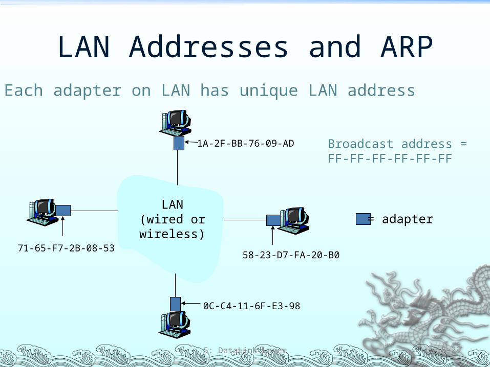
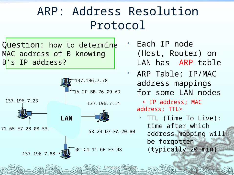
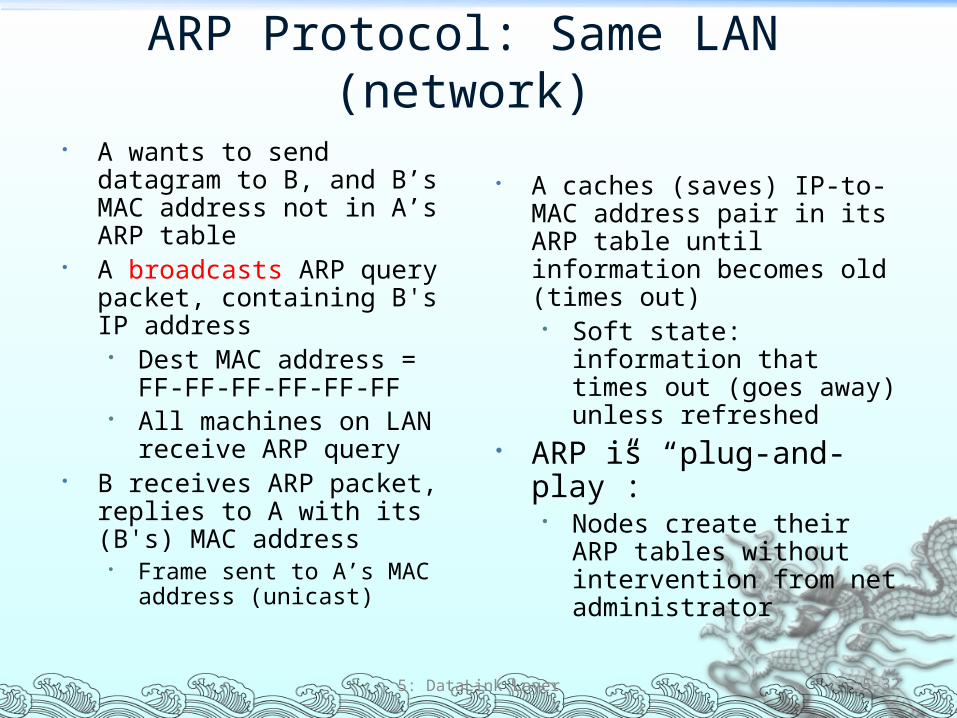
Link Layer 51 Introduction and
services 52 Error detection and
correction 53 Multiple access
protocols 54 Link-Layer Addressing 55 Ethernet
56 Hubs and switches 57 PPP
5 DataLink Layer 5-33
EthernetldquoDominantrdquo wired LAN technology Cheap $20 for 100Mbs First widely used LAN technology Simpler cheaper than token LANs and ATM Kept up with speed race 10 Mbps ndash 10 Gbps
5 DataLink Layer 5-34
Metcalfersquos Ethernetsketch
Star Topology Bus topology popular through mid 90s Now star topology prevails Connection choices hub or switch (more later)
5 DataLink Layer 5-35
hub orswitch
Ethernet uses CSMACD No slots Adapter doesnrsquot transmit if
it senses that some other adapter is transmitting that is carrier sense
Transmitting adapter aborts when it senses that another adapter is transmitting that is collision detection
Before attempting a retransmission adapter waits a random time that is random access
5 DataLink Layer 5-36
random time depends upon collisions so far
Ethernet CSMACD Algorithm
1 Adaptor receives datagram from network layer amp creates frame
2 If adapter senses channel idle it starts to transmit frame If it senses channel busy waits until channel idle and then transmits
3 If adapter transmits entire frame without detecting another transmission the adapter is done with frame
4 If adapter detects another transmission while transmitting aborts and sends jam signal
5 After aborting adapter enters exponential backoff after the mth collision adapter chooses a K at random from 012hellip2m-1 Adapter waits K512 bit times and returns to Step 2
5 DataLink Layer 5-37
Ethernetrsquos CSMACD (more)Jam Signal make sure all other
transmitters are aware of collision 48 bits
Bit time 1 microsec for 10 Mbps Ethernet for K=1023 wait time is about 50 msec
Exponential Backoff Goal adapt retransmission
attempts to estimated current load
Heavy load random wait will be longer
First collision choose K from 01 delay is K 512 bit transmission times
After second collision choose K from 0123hellip
After ten collisions choose K from 01234hellip1023
5 DataLink Layer 5-38
Link Layer 51 Introduction and
services 52 Error detection and
correction 53Multiple access
protocols 54 Link-Layer Addressing 55 Ethernet
56 Interconnections Hubs and switches
57 PPP
5 DataLink Layer 5-39
Hubs Physical Layer devices essentially repeaters operating
at bit levels repeat received bits on one interface to all other interfaces
Hubs can be arranged in a hierarchy (or multi-tier design) with backbone hub at its top
5 DataLink Layer 5-40
hub
hubhub
hub
Hubs (more)
Each connected LAN referred to as LAN segment Hubs do not isolate collision domains node may
collide with any node residing at any segment in LAN Hub Advantages
Simple inexpensive device Multi-tier provides graceful degradation portions of
the LAN continue to operate if one hub malfunctions Extends maximum distance between node pairs (100m
per Hub)
5 DataLink Layer 5-41
Hub Limitations Single collision domain results in no increase in max
throughput Multi-tier throughput same as single segment
throughput Individual LAN restrictions pose limits on number of nodes
in same collision domain and on total allowed geographical coverage
Cannot connect different Ethernet types (eg 10BaseT and 100baseT)
We now move on to switches
5 DataLink Layer 5-42
Switch Link layer device
Stores and forwards Ethernet frames Examines frame header and selectively forwards frame
based on MAC dest address When frame is to be forwarded on segment uses
CSMACD to access segment Transparent
Hosts are unaware of presence of switches Plug-and-play self-learning
Switches do not need to be configured
5 DataLink Layer 5-43
Switch Traffic Isolation Switch installation breaks subnet into LAN segments Switch filters packets
Same-LAN-segment frames not usually forwarded onto other LAN segments
Segments become separate collision domains
5 DataLink Layer 5-44
hub hub hub
switch
collision domain collision domain
collision domain
Switch Forwarding
5 DataLink Layer 5-45
How do determine onto which LAN segment to forward frame
Looks like a routing problem
hub
hubhub
switch1
2 3
Switch Self Learning A switch has a switch table Entry in switch table
(MAC Address Interface Time Stamp) Stale entries in table dropped (TTL can be 60 min)
Switch learns which hosts can be reached through which interfaces
When frame received switch ldquolearnsrdquo location of sender incoming LAN segment
Records senderlocation pair in switch table
5 DataLink Layer 5-46
Switch FilteringForwarding
When switch receives a frame
Index switch table using MAC dest address
if entry found for destinationthen
if dest on segment from which frame arrived then drop the frame
else forward the frame on interface indicated
else flood
5 DataLink Layer 5-47
forward on all but the interface on which the frame arrived
Switch Example
Suppose C sends frame to D
5 DataLink Layer 5-48
Switch receives frame from from C Notes in switch table that C is on interface 1 Because D is not in table switch forwards frame into interfaces
2 and 3
Frame received by D
hub
hub hub
switch
A
B CD
EF
G H
I
address interface
ABEG
1123
12 3
Switch Example
Suppose D replies back with frame to C
5 DataLink Layer 5-49
Switch receives frame from from D Notes in switch table that D is on interface 2 Because C is in table switch forwards frame only to interface 1
Frame received by C
hub
hub hub
switch
A
B CD
EF
G H
I
address interface
ABEGC
11231
Institutional Network
5 DataLink Layer 5-50
hub
hubhub
switch
to externalnetwork
router
IP subnet
mail server
web server
Chapter 5 Summary Principles behind data link layer services
Error detection correction Sharing a broadcast channel multiple access Link layer addressing
Instantiation and implementation of various link layer technologies
Ethernet Hubs switches IEEE 80211 (detailed see next Chapter) PPP
5 DataLink Layer 5-51
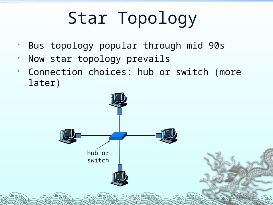
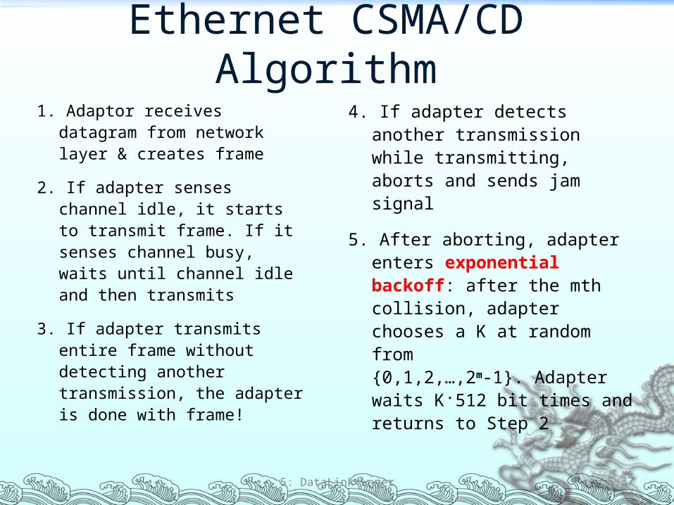
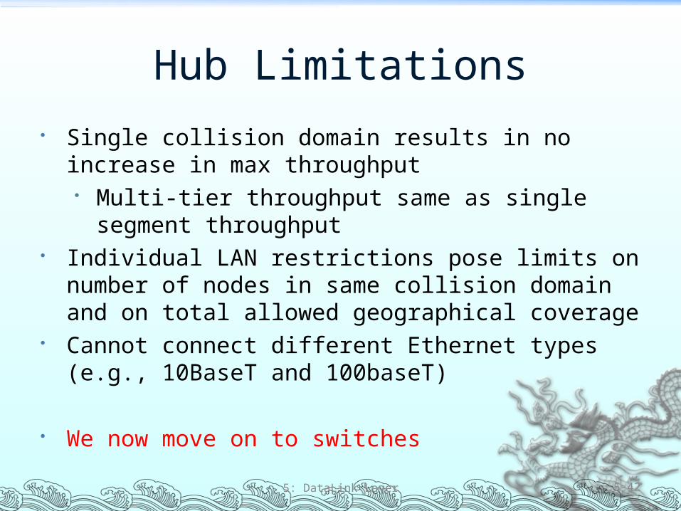
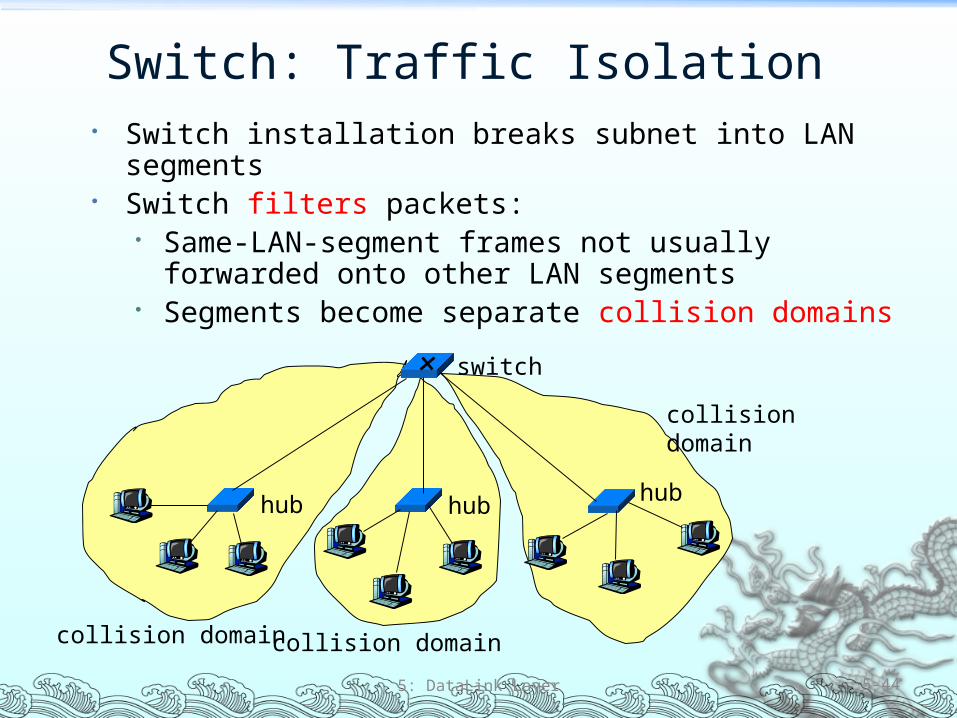
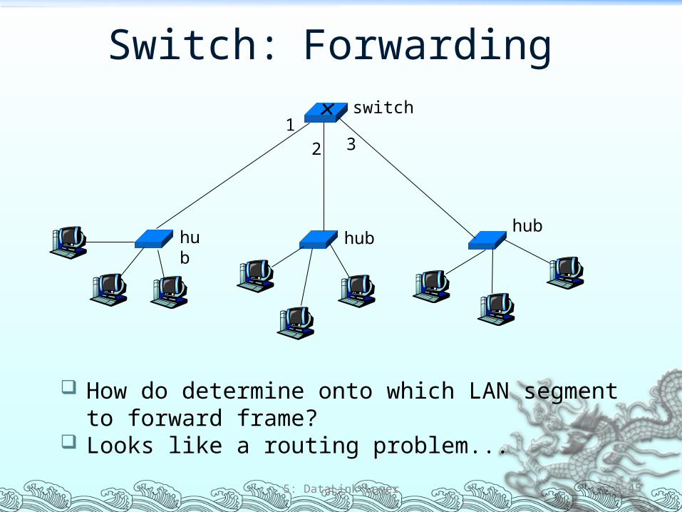
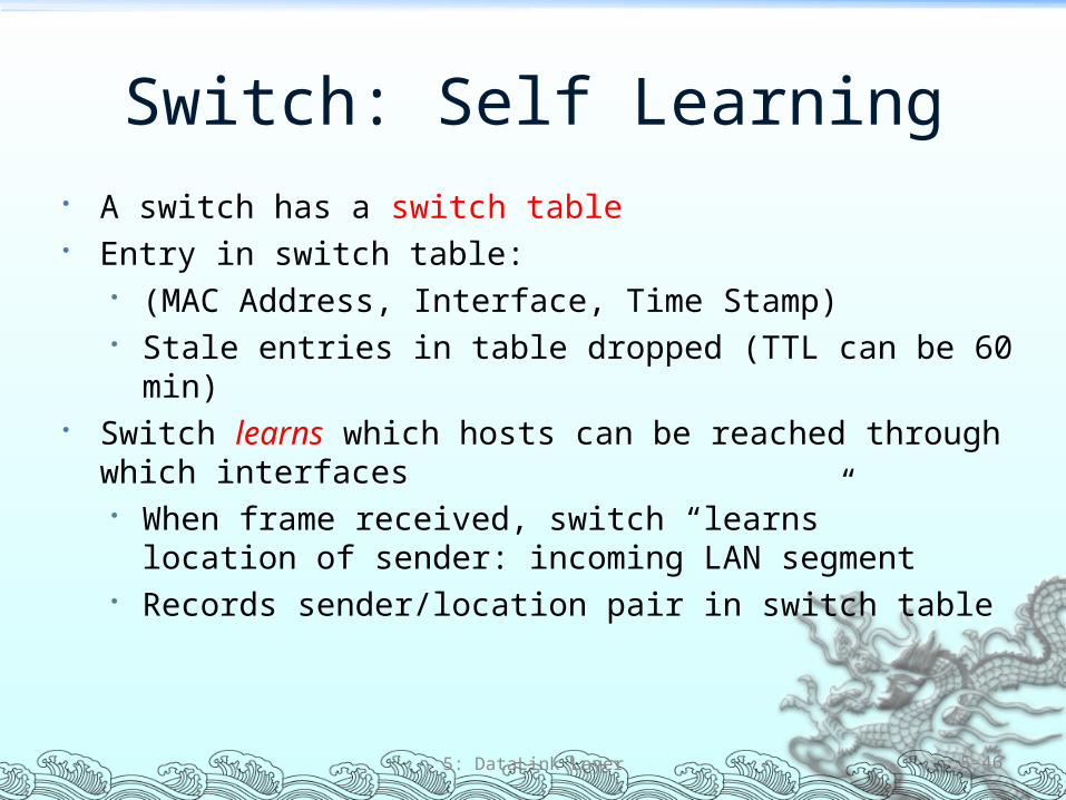
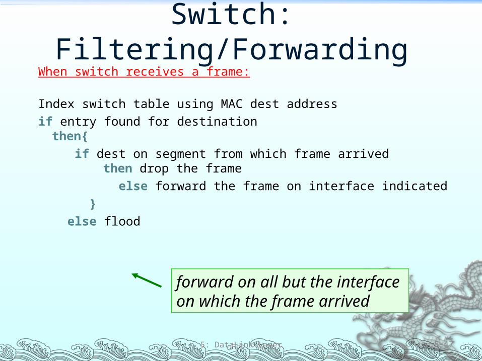
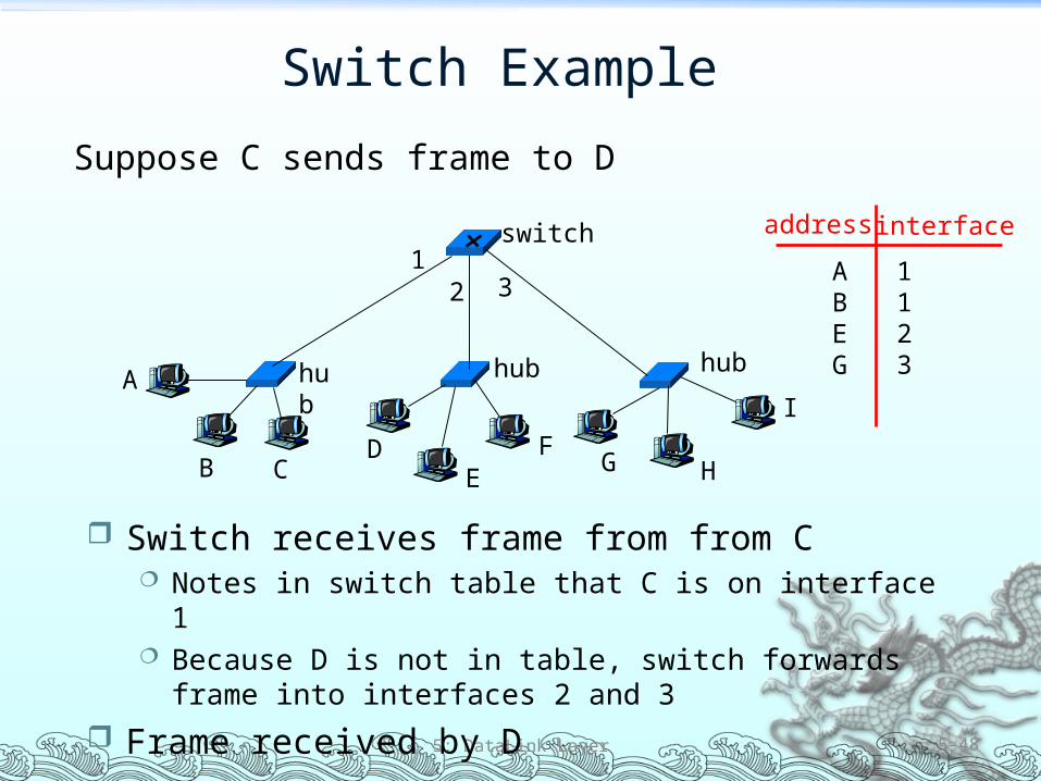
Switch Example
Suppose D replies back with frame to C
5 DataLink Layer 5-49
Switch receives frame from from D Notes in switch table that D is on interface 2 Because C is in table switch forwards frame only to interface 1
Frame received by C
hub
hub hub
switch
A
B CD
EF
G H
I
address interface
ABEGC
11231
Institutional Network
5 DataLink Layer 5-50
hub
hubhub
switch
to externalnetwork
router
IP subnet
mail server
web server
Chapter 5 Summary Principles behind data link layer services
Error detection correction Sharing a broadcast channel multiple access Link layer addressing
Instantiation and implementation of various link layer technologies
Ethernet Hubs switches IEEE 80211 (detailed see next Chapter) PPP
5 DataLink Layer 5-51
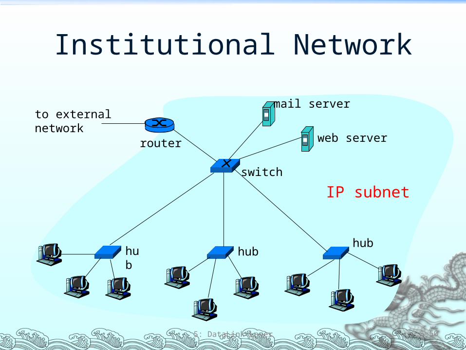