5-1 landing gear
TRANSCRIPT

8/20/2019 5-1 Landing Gear
http://slidepdf.com/reader/full/5-1-landing-gear 1/63
AMS 5 - 1
Landing Gear

8/20/2019 5-1 Landing Gear
http://slidepdf.com/reader/full/5-1-landing-gear 2/63
AMS 5 Part 1
AMS 5.1 Describe the constructional features,
explain the function and maintenance
procedures of landing gear components.

8/20/2019 5-1 Landing Gear
http://slidepdf.com/reader/full/5-1-landing-gear 3/63
Landing Gear
Configurations
ric!cle landing gear

8/20/2019 5-1 Landing Gear
http://slidepdf.com/reader/full/5-1-landing-gear 4/63
Landing Gear Configurations
Con"entional landing gear

8/20/2019 5-1 Landing Gear
http://slidepdf.com/reader/full/5-1-landing-gear 5/63
Classification of Landing Gear
The landing gear of an aircraft serves a numberof very important functions.
It:
Supports the aircraft during ground operations,Dampens vibrations when the aircraft is being
taxied or towed, and
Cushions the landing impact.
8/20/2019 5-1 Landing Gear
http://slidepdf.com/reader/full/5-1-landing-gear 6/63
Classification of Landing Gear
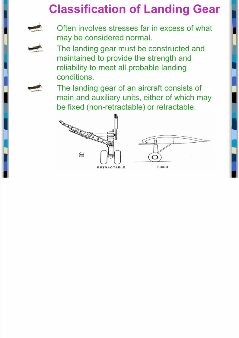
ften involves stresses far in excess of what
may be considered normal.The landing gear must be constructed and
maintained to provide the strength and
reliability to meet all probable landing
conditions.
The landing gear of an aircraft consists of
main and auxiliary units, either of which may
be fixed !non"retractable# or retractable.

8/20/2019 5-1 Landing Gear
http://slidepdf.com/reader/full/5-1-landing-gear 7/63
The main landing gear provides the main support of
the aircraft on land or water.It may include a combination of: wheels, floats, s$is,
shoc$ absorbing e%uipment,‑
bra$es, retracting mechanism, controls,
warning devices, cowling, fairing and structural members needed for
attachment to the primary structure of the aircraft.
Main Landing Gear

8/20/2019 5-1 Landing Gear
http://slidepdf.com/reader/full/5-1-landing-gear 8/63
The auxiliary landing gear
consists of:
Tail or nose landing wheel
installations, including steering
mechanisms&
s$ids& and
outboard pontoons, etc., with
the necessary cowling and
reinforcements.
Auxiliar! Landing Gear
8/20/2019 5-1 Landing Gear
http://slidepdf.com/reader/full/5-1-landing-gear 9/63
'on"absorbing landing gear includes those types oflanding gear that do not dissipate the energy of the
aircraft contacting the ground during landing.
They only store the energy to return it to the aircraft
at a later time.
These types of gear include:
rigid landing gear,
shoc$ cord landing gear, and‑
spring type gear.‑
#on$Absorbing Landing Gear

8/20/2019 5-1 Landing Gear
http://slidepdf.com/reader/full/5-1-landing-gear 10/63
%igid Landing Gear
Commonly found on helicopters and sailplanes.
(igidly mounted to the aircraft with no specific
component to cushion the ground contact other
than through the flexing of the landing gear or
airframe structure.
8/20/2019 5-1 Landing Gear
http://slidepdf.com/reader/full/5-1-landing-gear 11/63
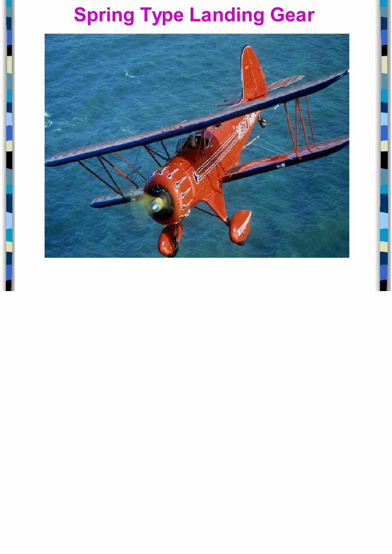
Spring !pe Landing Gear

8/20/2019 5-1 Landing Gear
http://slidepdf.com/reader/full/5-1-landing-gear 12/63
Shoc$ absorbing landing gear dissipates the impact‑
energy of landing by forcing a fluid through a
restriction.
)ost of these types of landing gear do this
The movement of this fluid generates heat, and theheat is radiated into the surrounding atmosphere,
dissipating the landing energy.
There are two types of shoc$ absorbing landing‑
gear commonly used, these are the:
spring oleo and‑
air"oleo types
Shoc& Absorbing Landing Gear ‑

8/20/2019 5-1 Landing Gear
http://slidepdf.com/reader/full/5-1-landing-gear 13/63
Spring 'leo Struts Consist of a piston type structure and a heavy,
coiled spring.
The piston and cylinder arrangement provides an
oil chamber and an orifice through which oil is
forced during landing.
*hen the aircraft is airborne,the strut is extended,
and the oil flows by gravity to the lower chamber.
*hen the plane lands, the piston with the orificeis forced downward into the cylinder and the oil is
forced through the orifice into the upper chamber.
This action provides a cushioning effect to absorb
the primary shoc$ of landing.
+s the strut collapses, the coil spring iscompressed, thus providing additional cushioning.
The spring supports the aircraft weight on the
ground and during taxiing.
The oleo strut absorbs the shoc$ of landing.

8/20/2019 5-1 Landing Gear
http://slidepdf.com/reader/full/5-1-landing-gear 14/63
'il and Air 'leo Struts he c!linder is di"ided into t(o
compartments b! a piston tube
he piston fits into the c!linder around the
tube.
A tapered metering pin stic&s through the
hole in the bottom of the piston tube.
o fill the strut, the piston is pushed all of
the (a! into the c!linder, (hich is filled
(ith h!draulic fluid to the le"el of the
charging "al"e.
)ith the (eight of the aircraft on the
(heel, enough compressed air or nitrogen
is pumped through the charging "al"e to
raise the aircraft until the piston stic&s out
of the c!linder for a specified distance.
8/20/2019 5-1 Landing Gear
http://slidepdf.com/reader/full/5-1-landing-gear 15/63
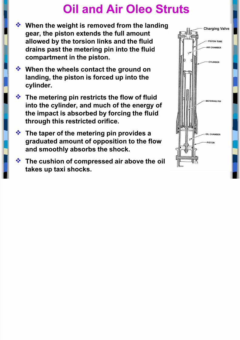
'il and Air 'leo Struts )hen the (eight is remo"ed from the landing
gear, the piston extends the full amount
allo(ed b! the torsion lin&s and the fluiddrains past the metering pin into the fluid
compartment in the piston.
)hen the (heels contact the ground on
landing, the piston is forced up into the
c!linder.
he metering pin restricts the flo( of fluid
into the c!linder, and much of the energ! of
the impact is absorbed b! forcing the fluid
through this restricted orifice.
he taper of the metering pin pro"ides a
graduated amount of opposition to the flo(
and smoothl! absorbs the shoc&.
he cushion of compressed air abo"e the oil
ta&es up taxi shoc&s.
8/20/2019 5-1 Landing Gear
http://slidepdf.com/reader/full/5-1-landing-gear 16/63
leo pneumatic undercarriages should be examined‑
for& crac$s or damage to mounting structure,
corrosion, and
wear at pivot points.
In addition, the following maintenance is necessary: )achined surfaces of the strut inner cylinder should
be wiped free of dust or dirt at fre%uent intervals, to
prevent damage to the lower cylinder seals.
+ lint free cloth, soa$ed in the fluid used in the strut,‑
should be used for this purpose.
Maintenance
8/20/2019 5-1 Landing Gear
http://slidepdf.com/reader/full/5-1-landing-gear 17/63
he extension of the inner c!linder, i.e. the
length of the "isible portion of the inner
c!linder,should be chec&ed fre*uentl! against the
centre of gra"it!+loading graphs pro"ided in
the appro"ed Maintenance Manual.
Note:
Because of the tightness of the sealing glands in
the strut, it may be necessary to rock the
aircraft to free the inner cylinder and obtainthe true extension
Maintenance

8/20/2019 5-1 Landing Gear
http://slidepdf.com/reader/full/5-1-landing-gear 18/63
he strut should be inspected fre*uentl! for fluid
lea&s. f lea&s are due to fault! glands the glands ma! be
replaced,
f the! are due to a scored inner c!linder, the strut
should be changed. or*ue lin&s, steering arms, and damper
attachments should be chec&ed for securit!, and
for crac&s, (ear or an! other damage.
All mo"ing parts of the undercarriage should belubricated on assembl!, and at the inter"als
specified in the appro"ed Maintenance Schedule.
Maintenance

8/20/2019 5-1 Landing Gear
http://slidepdf.com/reader/full/5-1-landing-gear 19/63
DC tail wheel assembly
The tail wheel is mounted on
a short spring, oleo, or other
assembly on the bottom of
the fuselage near the rudder.
The tail wheel may be fixed in
alignment with the fuselagelongitudinal axis, or it may be
designed to rotate, allowing
the aircraft to turn easily.
ail )heel

8/20/2019 5-1 Landing Gear
http://slidepdf.com/reader/full/5-1-landing-gear 20/63
-ixed Alignment ail )heels
-ixed alignment tail (heels are found onl! onaircraft such as gliders, (hich are not normall!
taxied.
ail )heel
Mo"able ail )heelsA tail (heel that can rotate ma! be steerable,
full s(i"elling, and loc&able.
A steerable tail (heel responds to cabin ruddercontrols to aid in controlling aircraft direction of
mo"ement on the ground.
8/20/2019 5-1 Landing Gear
http://slidepdf.com/reader/full/5-1-landing-gear 21/63
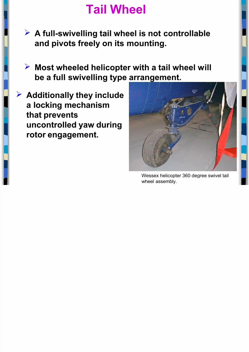
*essex helicopter - degree swivel tailwheel assembly.
ail )heel
A full$s(i"elling tail (heel is not controllable
and pi"ots freel! on its mounting.
Most (heeled helicopter (ith a tail (heel (ill
be a full s(i"elling t!pe arrangement.
Additionall! the! include
a loc&ing mechanism
that pre"ents
uncontrolled !a( during
rotor engagement.

8/20/2019 5-1 Landing Gear
http://slidepdf.com/reader/full/5-1-landing-gear 22/63
-ixed Alignment ail )heels
/ Most steerable tail (heels incorporate afree$s(i"el capabilit! (hen the pilot
ma&es "er! tight turns using the main
(heel bra&es.
/ A loc&able mechanism is used (ithsome tail (heels to aid in directional
control during ta&eoff and landing.
/ Mechanism loc&s the tail (heel in
alignment (ith the aircraft longitudinalaxis.
/ )hen the loc& is disengaged, the tail
(heel returns to its full s(i"el or‑
steerable operation.
ail )heel
8/20/2019 5-1 Landing Gear
http://slidepdf.com/reader/full/5-1-landing-gear 23/63
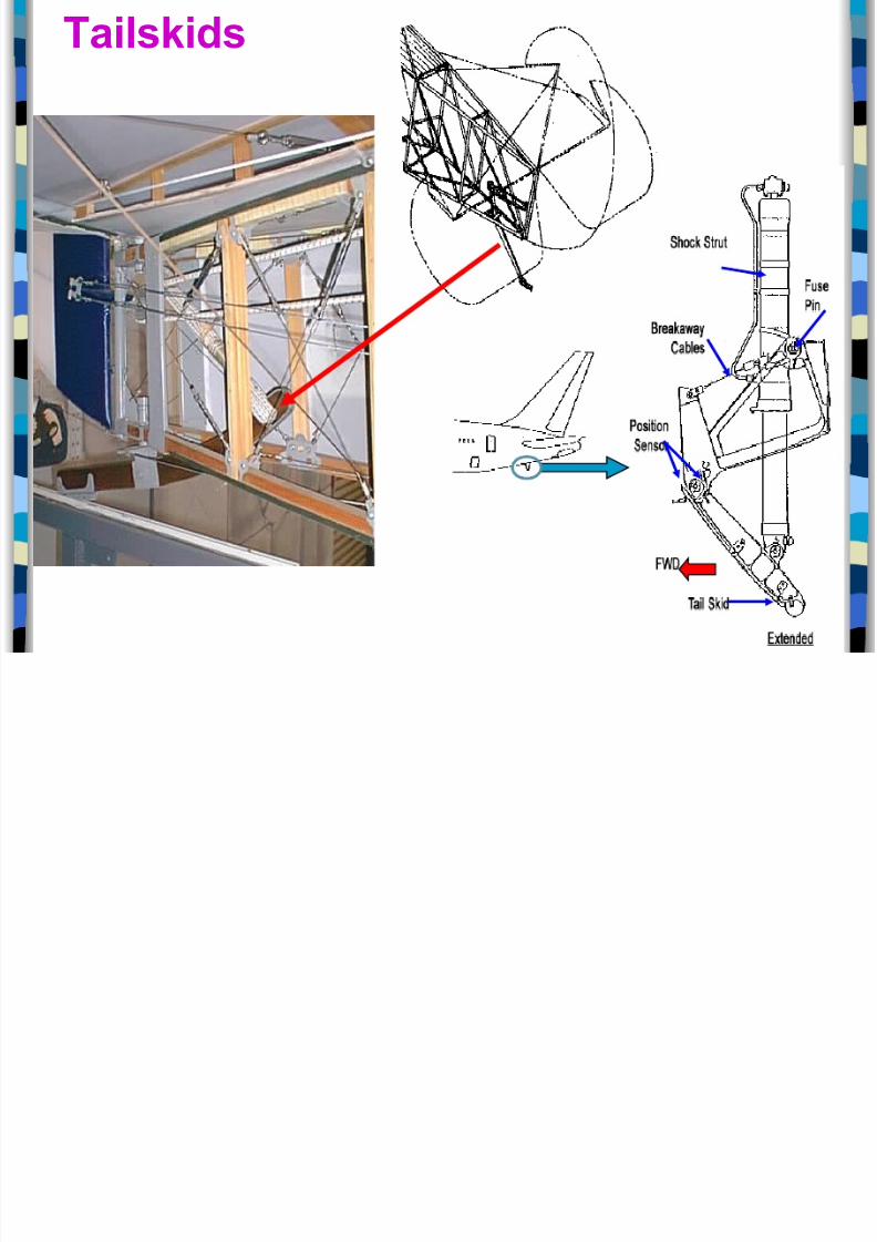
ails&ids
ll d -l t

8/20/2019 5-1 Landing Gear
http://slidepdf.com/reader/full/5-1-landing-gear 24/63
ulls and -loats
f an aircraft is afl!ing boat, it has a
hull for flotation and
then ma! need onl!
(ing$tip floats.
Amphibious aircraft
ha"e floats or a hull
for operating on
(ater and
retractable (heels
for land operation.
Aircraft operated from (ater
ma! be pro"ided (ith either a
single float or a double float,depending upon the design and
construction/
ll d -l t

8/20/2019 5-1 Landing Gear
http://slidepdf.com/reader/full/5-1-landing-gear 25/63
ulls and -loats
f an aircraft is afl!ing boat, it has a
hull for flotation and
then ma! need onl!
(ing$tip floats.
Amphibious aircraft
ha"e floats or a hull
for operating on
(ater and
retractable (heels
for land operation.
Aircraft operated from
(ater ma! be pro"ided
(ith either a single floator a double float,
depending upon the
design and construction/
S&i

8/20/2019 5-1 Landing Gear
http://slidepdf.com/reader/full/5-1-landing-gear 26/63
S&is
S&i

8/20/2019 5-1 Landing Gear
http://slidepdf.com/reader/full/5-1-landing-gear 27/63
S&isS$is are used for operating on snow and
ice.
The s$is may be made of wood, metal, orcomposite materials.
There are three basic styles of s$is.
Conventional s$i,
*heel s$i, and‑
(etractable wheel s$i.‑
S&i
8/20/2019 5-1 Landing Gear
http://slidepdf.com/reader/full/5-1-landing-gear 28/63
Fwd
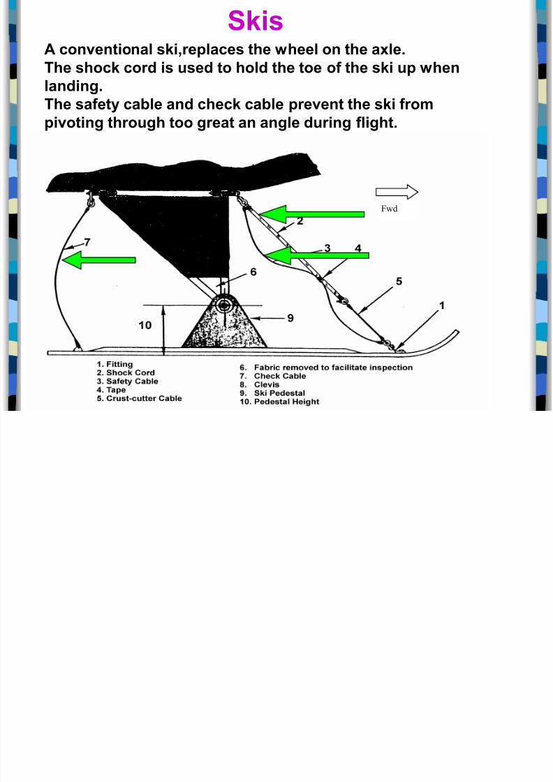
S&isA con"entional s&i,replaces the (heel on the axle.
he shoc& cord is used to hold the toe of the s&i up (hen
landing.
he safet! cable and chec& cable pre"ent the s&i frompi"oting through too great an angle during flight.
S&i
8/20/2019 5-1 Landing Gear
http://slidepdf.com/reader/full/5-1-landing-gear 29/63
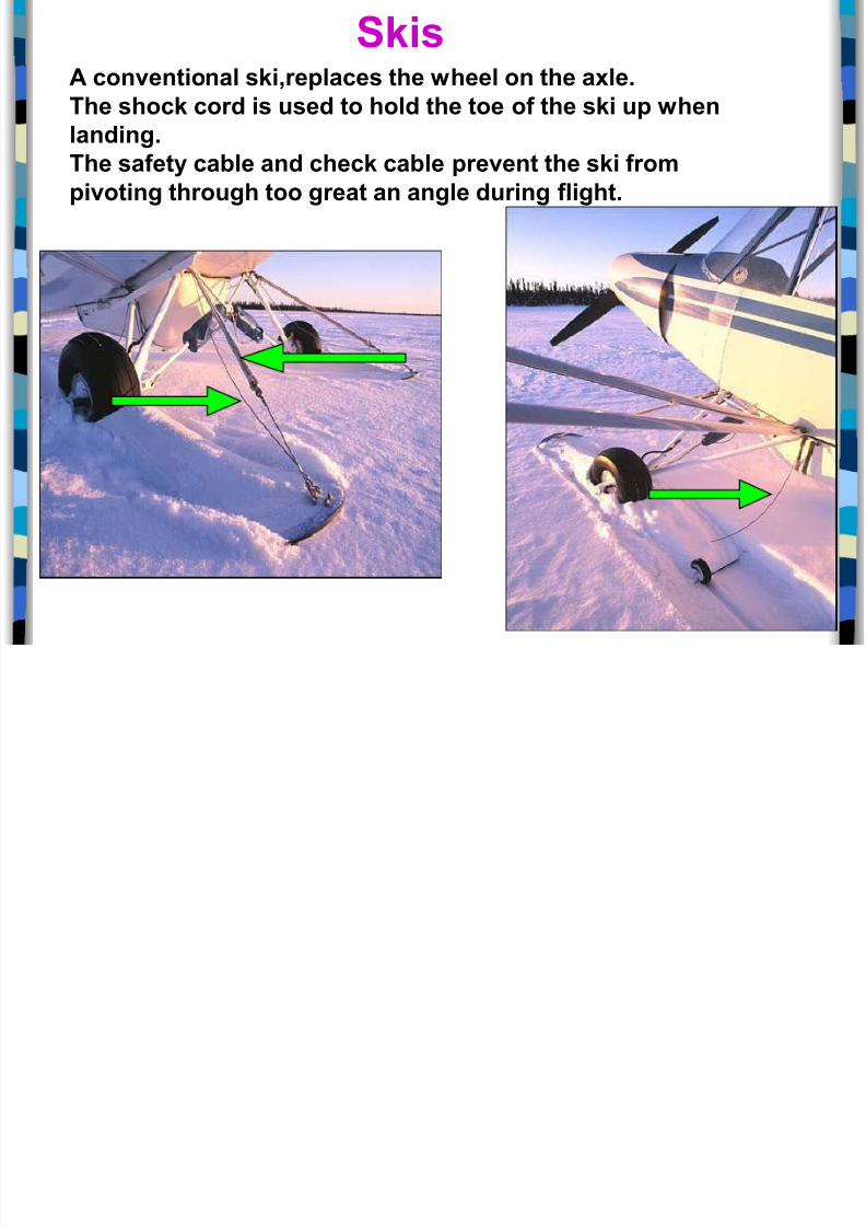
S&isA con"entional s&i,replaces the (heel on the axle.
he shoc& cord is used to hold the toe of the s&i up (hen
landing.
he safet! cable and chec& cable pre"ent the s&i frompi"oting through too great an angle during flight.
S&i

8/20/2019 5-1 Landing Gear
http://slidepdf.com/reader/full/5-1-landing-gear 30/63
S&is
he s&i has a portion cut out that allo(s the
tire to extend slightl! belo( the s&i so that the
aircraft can be operated from con"entional
run(a!s (ith the (heels or from sno( or ice
surfaces using the s&i.
he (heel s&i is designed to mount on the aircraft along (ith the tire.‑
S&i

8/20/2019 5-1 Landing Gear
http://slidepdf.com/reader/full/5-1-landing-gear 31/63
S&is
his arrangement has a small (heel mounted on the heel of the
s&i so that it does not drag on con"entional run(a!s.
S&i

8/20/2019 5-1 Landing Gear
http://slidepdf.com/reader/full/5-1-landing-gear 32/63
S&is
%etractable (heel s&i arrangements ha"e the‑s&i mounted on a common axle (ith the (heel.
he s&i can be extended belo( the le"el of the
(heel for landing on sno( or ice.
he s&i can be retracted abo"e the bottom ofthe (heel for operations from con"entional
run(a!s.
A h!draulic s!stem is commonl! used for the
retraction s!stem operation.
nspection And %epair
8/20/2019 5-1 Landing Gear
http://slidepdf.com/reader/full/5-1-landing-gear 33/63
Inspection of floats and s$is involves examinationfor damage due to&
corrosion,
collision with other ob0ects,
hard landings, and
other conditions that may lead to failure.
nspection And %epair
'f -loats And S&is
ubular StructuresTubular structures may be repaired using standard
welded repair procedures for tubular structures.
nspection And %epair
8/20/2019 5-1 Landing Gear
http://slidepdf.com/reader/full/5-1-landing-gear 34/63
1loats and 2ulls
1loats should be carefully inspected for corrosion
damage at periodic intervals, especially if the aircraft
is flown from salt water.
If small blisters are noticed on the paint, either insideor outside the float, the paint should be removed and
the area examined.
If corrosion is found to exist, the area should be
cleaned thoroughly, and a coat of corrosion inhibiting‑
material applied.
If the corrosion penetrates the metal to an appreciable
depth, it is advisable that a patch be applied in
accordance with approved practice.
nspection And %epair
'f -loats And S&is
nspection And %epair

8/20/2019 5-1 Landing Gear
http://slidepdf.com/reader/full/5-1-landing-gear 35/63
-loats and ulls
Special attention should be given to brace wire fittings and
water rudder control systems.
If the floats or hull has retractable landing gear, a retraction
chec$ should be performed along with the other
recommendations mentioned for retractable landing gearsystems.
Sheet metal floats should be repaired using approved
practices,
the seams between sections of sheet metal should bewaterproofed with suitable fabric and sealing compound.
+ float that has undergone repairs should be tested by filling it
with water and allowing it to stand for at least 34 hrs to see if
any lea$s develop.
nspection And %epair
'f -loats And S&is
nspection And %epair
8/20/2019 5-1 Landing Gear
http://slidepdf.com/reader/full/5-1-landing-gear 36/63
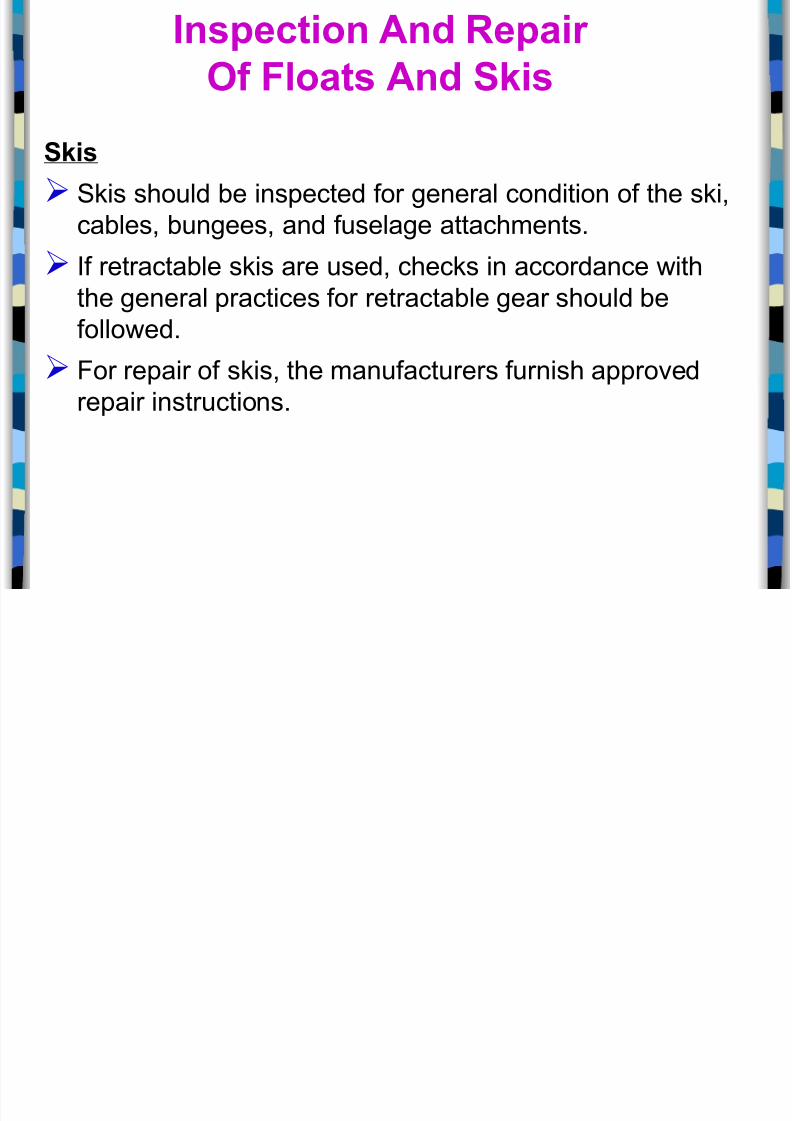
S&is
S$is should be inspected for general condition of the s$i,
cables, bungees, and fuselage attachments.
If retractable s$is are used, chec$s in accordance with
the general practices for retractable gear should be
followed.
1or repair of s$is, the manufacturers furnish approved
repair instructions.
nspection And %epair
'f -loats And S&is
Main Landing Gear

8/20/2019 5-1 Landing Gear
http://slidepdf.com/reader/full/5-1-landing-gear 37/63
Single +xle,
Dual +xle,
Single Tandem, and
Dual Tandem !Truc$ or 5ogie#.
Main Landing Gear
The ma0or design types:
8/20/2019 5-1 Landing Gear
http://slidepdf.com/reader/full/5-1-landing-gear 38/63
railing Lin& Main Landing Gear

8/20/2019 5-1 Landing Gear
http://slidepdf.com/reader/full/5-1-landing-gear 39/63
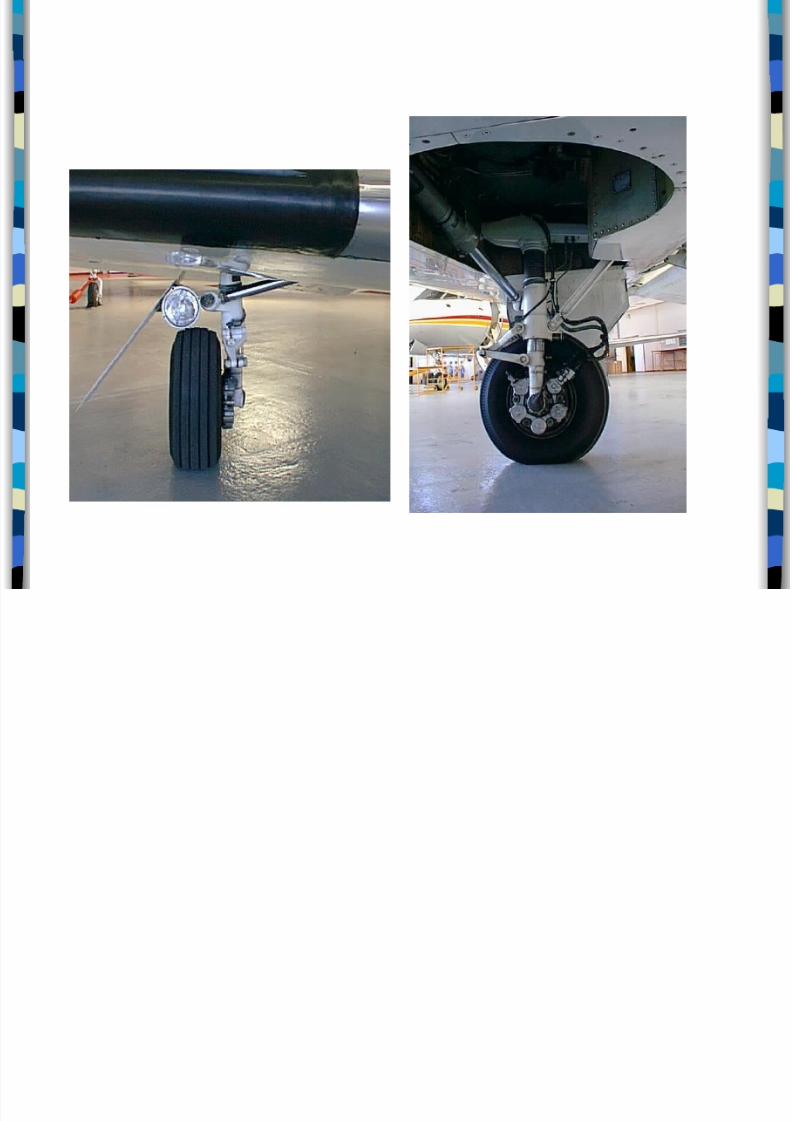
g g
The trailing lin$ design provides a softer
landing as the trailing arm is able to pivot up
around the forward landing gear strut. This
action provides more oleo travel than the
vertical oleo used with the Cessna Citation
II, shown on the previous page.
Photographs co rtes of
8/20/2019 5-1 Landing Gear
http://slidepdf.com/reader/full/5-1-landing-gear 40/63
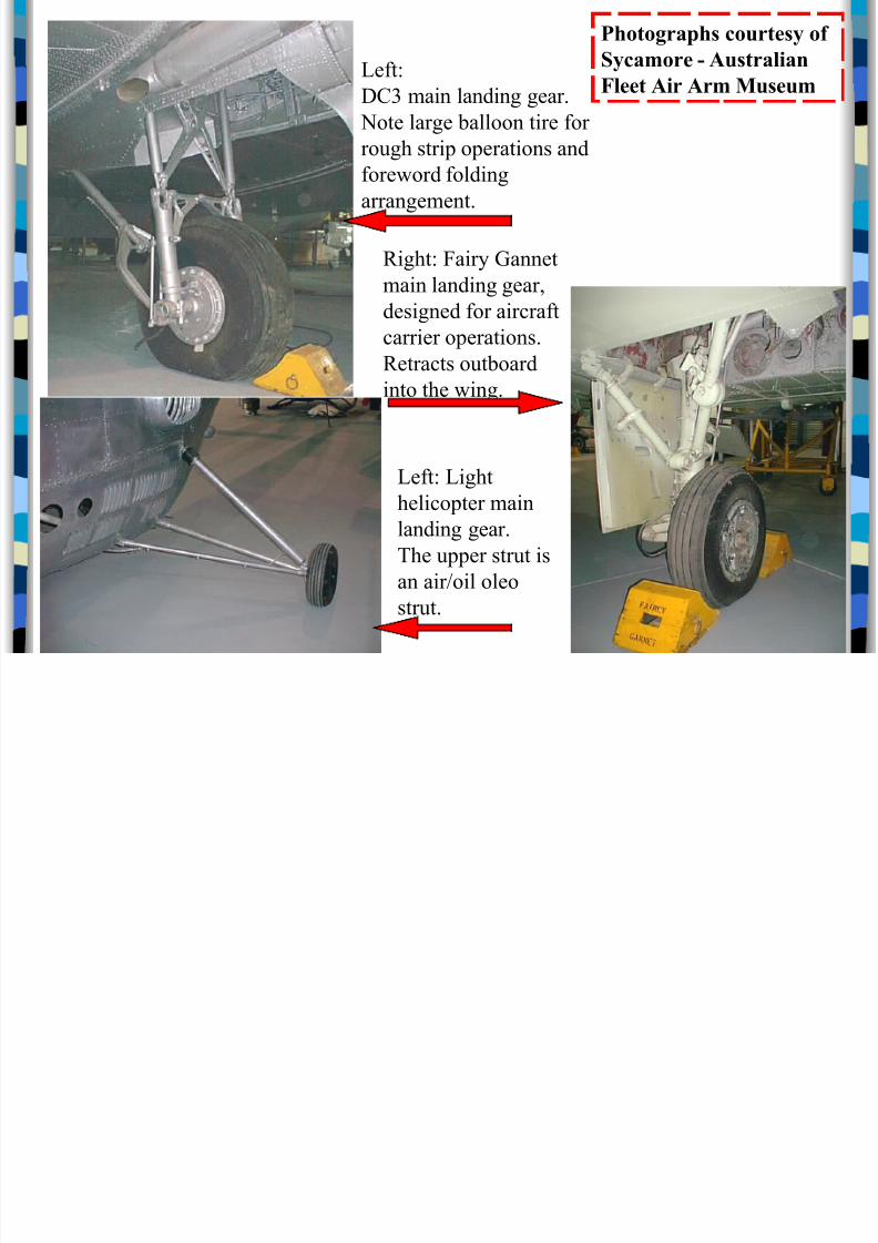
Left:
DC3 main landing gear.
Note large balloon tire for
rough strip operations and
foreword folding
arrangement.
Right: Fairy Gannet
main landing gear,
designed for airraftarrier operations.
Retrats outboard
into the wing.
Left: Light
heliopter main
landing gear.
!he upper strut is
an air"oil oleo
strut.
Photographs courtesy of
Sycamore - Australian
Fleet Air Arm Museum
8/20/2019 5-1 Landing Gear
http://slidepdf.com/reader/full/5-1-landing-gear 41/63
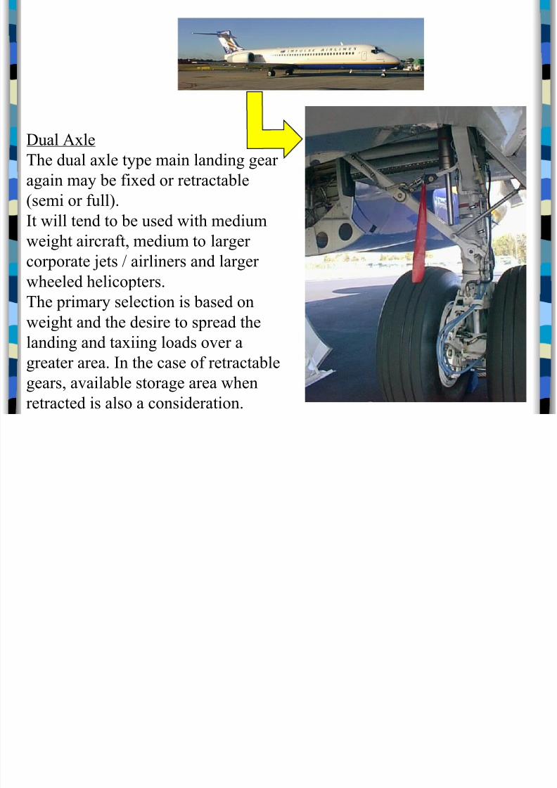
Dual #$le
!he dual a$le type main landing gear
again may be fi$ed or retratable
%semi or full&.'t will tend to be used with medium
weight airraft, medium to larger
orporate (ets " airliners and larger
wheeled heliopters.
!he primary seletion is based on
weight and the desire to spread the
landing and ta$iing loads o)er a
greater area. 'n the ase of retratable
gears, a)ailable storage area when
retrated is also a onsideration.
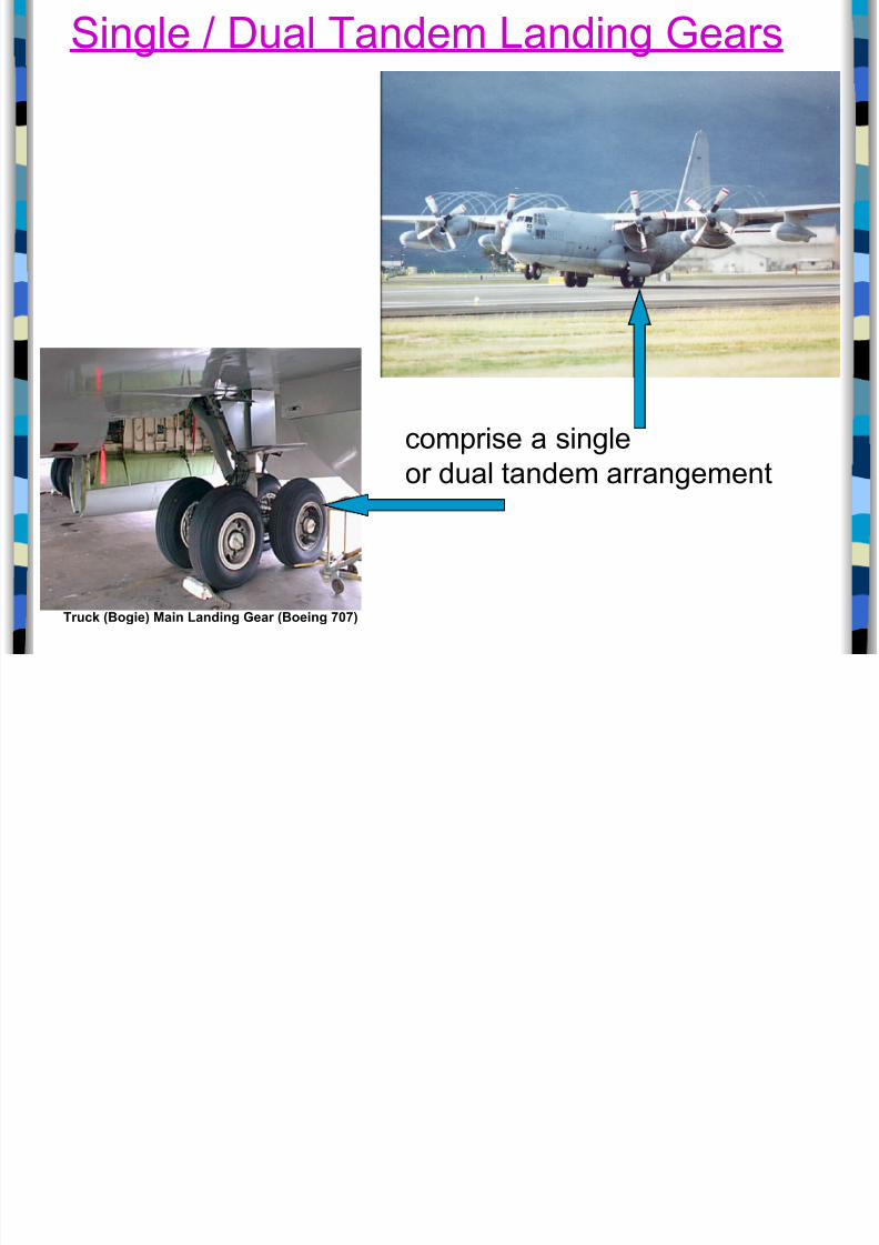
Single 6 Dual Tandem 7anding 8ears
8/20/2019 5-1 Landing Gear
http://slidepdf.com/reader/full/5-1-landing-gear 42/63
ruc& 0ogie2 Main Landing Gear 0oeing 3432
comprise a single
or dual tandem arrangement
Single 6 Dual Tandem 7anding 8ears
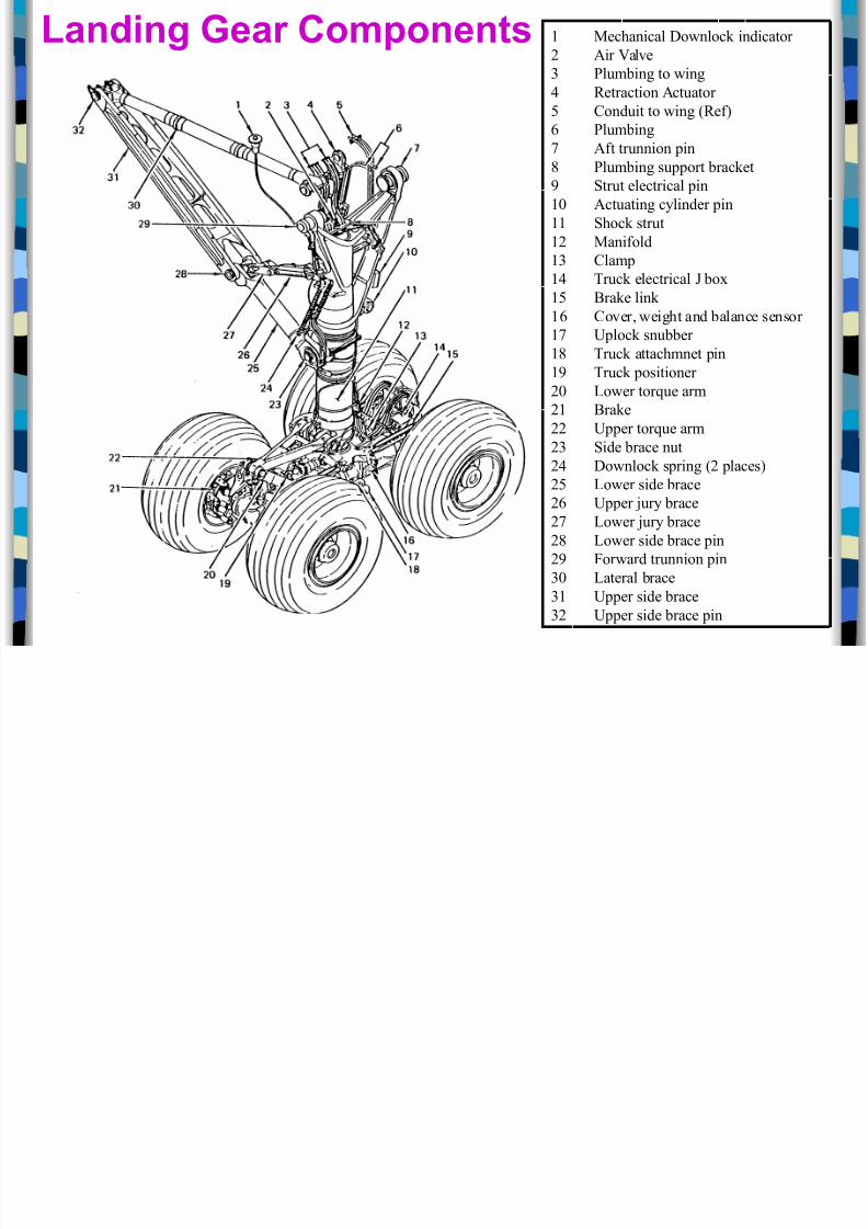
* + h i l D l i di tLanding Gear Components
8/20/2019 5-1 Landing Gear
http://slidepdf.com/reader/full/5-1-landing-gear 43/63
* +ehanial Downlo indiator
- #ir al)e
3 /lumbing to wing
0 Retration #tuator
1 Conduit to wing %Ref&
2 /lumbing
#ft trunnion pin
4 /lumbing support braet
5 6trut eletrial pin
*7 #tuating ylinder pin
** 6ho strut
*- +anifold
*3 Clamp
*0 !ru eletrial 8 bo$
*1 9rae lin
*2 Co)er, weight and balane sensor
* plo snubber
*4 !ru attahmnet pin
*5 !ru positioner
-7 Lower tor;ue arm
-* 9rae
-- pper tor;ue arm
-3 6ide brae nut
-0 Downlo spring %- plaes&-1 Lower side brae
-2 pper (ury brae
- Lower (ury brae
-4 Lower side brae pin
-5 Forward trunnion pin
37 Lateral brae
3* pper side brae
3- pper side brae pin
Landing Gear Components
runnion

8/20/2019 5-1 Landing Gear
http://slidepdf.com/reader/full/5-1-landing-gear 44/63
runnion
The portion of the landing"gear assembly that isattached to the airframe
Supported at its ends by bearing assemblies that
allow the gear to pivot during retraction and extension
The landing"gear strut extends down from the
approximate centre of the trunnion
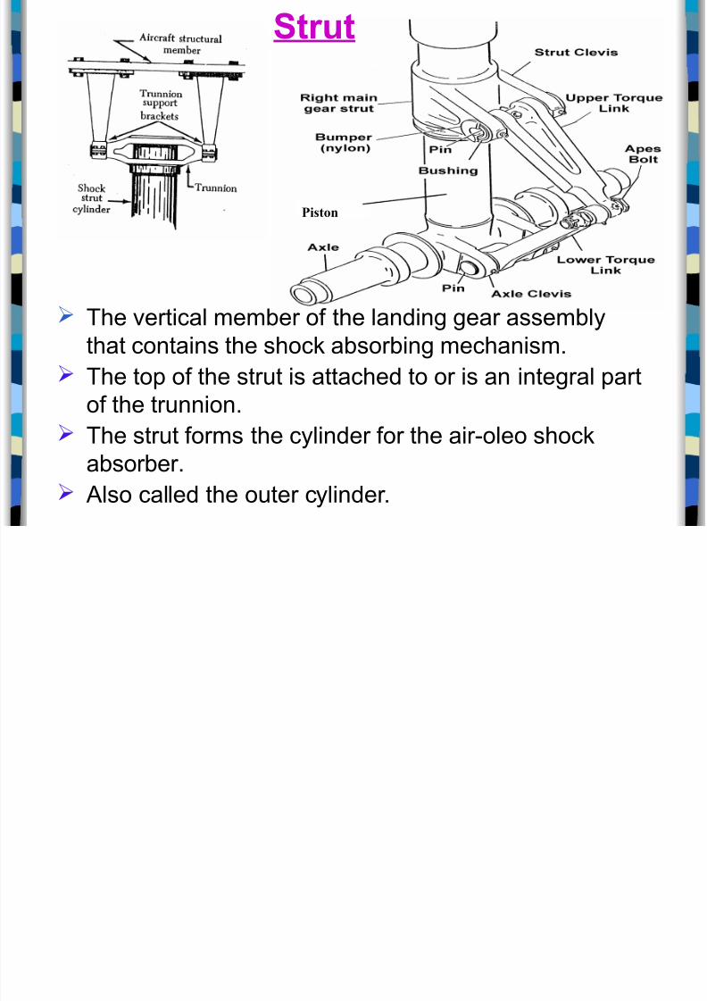
Strut
8/20/2019 5-1 Landing Gear
http://slidepdf.com/reader/full/5-1-landing-gear 45/63
Piston
The vertical member of the landing gear assembly
that contains the shoc$ absorbing mechanism.
The top of the strut is attached to or is an integral partof the trunnion.
The strut forms the cylinder for the air"oleo shoc$
absorber.
+lso called the outer cylinder.
Strut
iston

8/20/2019 5-1 Landing Gear
http://slidepdf.com/reader/full/5-1-landing-gear 46/63
Piston
The moving portion of the
air oleo shoc$ absorber.‑
1its inside of the strut, and
The bottom of the piston is
attached to the axle or other
component on which the axleis mounted.
ther terms used for the
piston are
piston rod,piston tube, and
inner cylinder.
iston
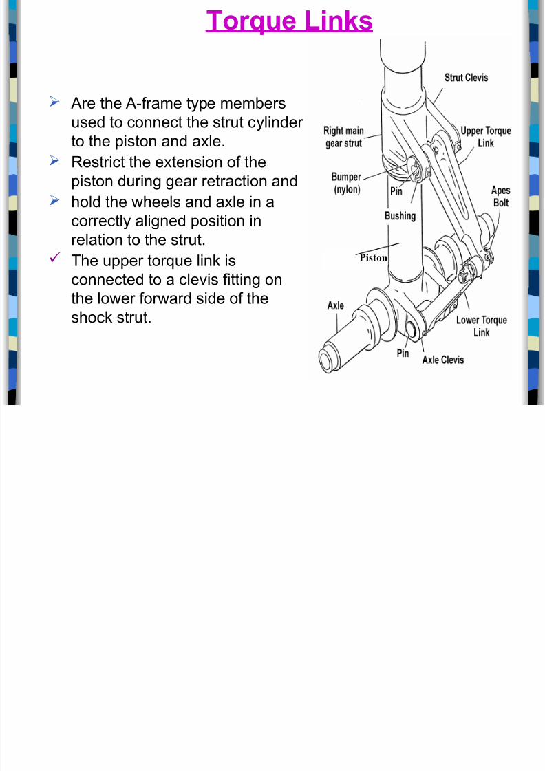
or*ue Lin&s
8/20/2019 5-1 Landing Gear
http://slidepdf.com/reader/full/5-1-landing-gear 47/63
+re the +"frame type membersused to connect the strut cylinder
to the piston and axle.
(estrict the extension of the
piston during gear retraction and
hold the wheels and axle in a
correctly aligned position in
relation to the strut.
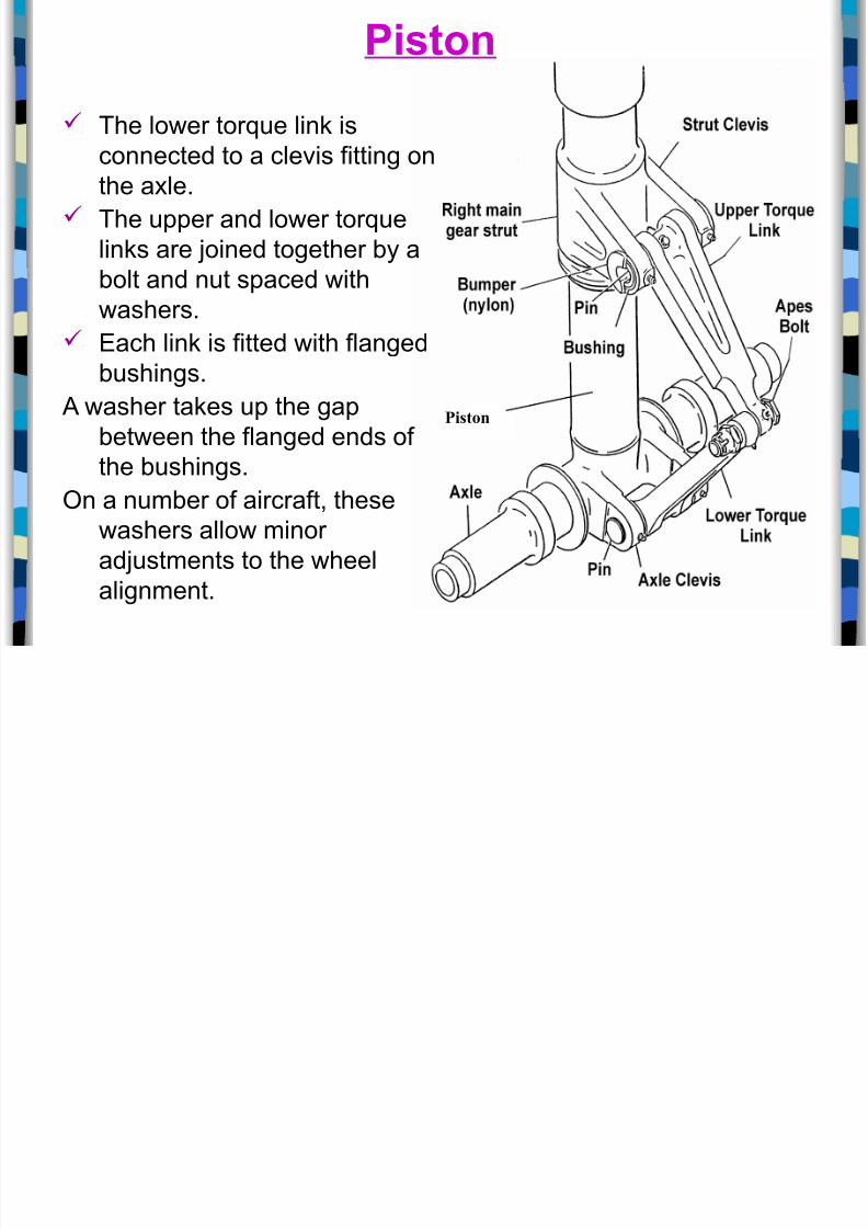
The upper tor%ue lin$ is
connected to a clevis fitting on
the lower forward side of the
shoc$ strut.
or*ue Lin&s
Piston
iston
8/20/2019 5-1 Landing Gear
http://slidepdf.com/reader/full/5-1-landing-gear 48/63
Piston
The lower tor%ue lin$ is
connected to a clevis fitting onthe axle.
The upper and lower tor%ue
lin$s are 0oined together by a
bolt and nut spaced with
washers. 9ach lin$ is fitted with flanged
bushings.
+ washer ta$es up the gap
between the flanged ends of
the bushings.n a number of aircraft, these
washers allow minor
ad0ustments to the wheel
alignment.
iston
ruc&

8/20/2019 5-1 Landing Gear
http://slidepdf.com/reader/full/5-1-landing-gear 49/63
7ocated on the bottom of
the piston
2as the axles attached to
it.
sed when wheels are tobe placed in tandem !one
behind the other# or in a
dual tandem arrangement.
ruc&
Can tilt fore and aft at the piston connection to allow for
changes in aircraft attitude during ta$eoff and landing
and during taxiing.
+lso called a bogie.

8/20/2019 5-1 Landing Gear
http://slidepdf.com/reader/full/5-1-landing-gear 50/63
Shimm! Dampers
8/20/2019 5-1 Landing Gear
http://slidepdf.com/reader/full/5-1-landing-gear 51/63
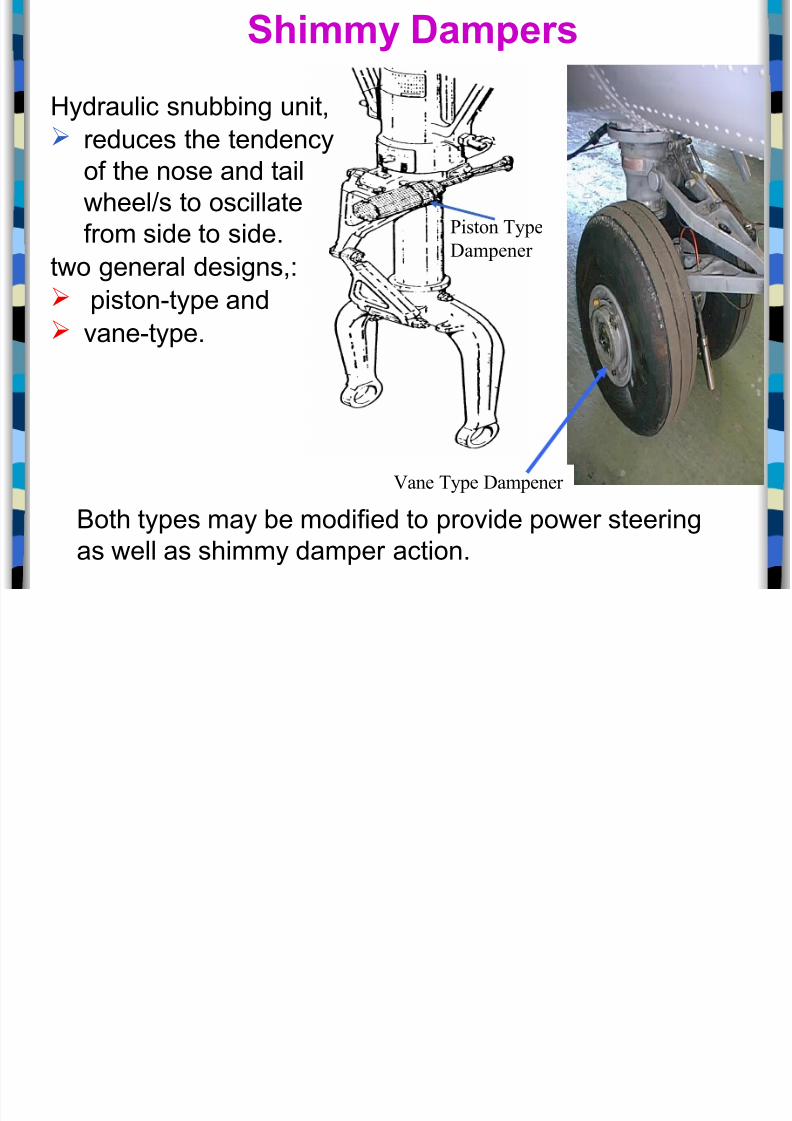
/iston !ype
Dampener
ane !ype Dampener
Shimm! Dampers
2ydraulic snubbing unit,
reduces the tendencyof the nose and tail
wheel6s to oscillate
from side to side.
two general designs,: piston"type and vane"type.
5oth types may be modified to provide power steering
as well as shimmy damper action.
iston$!pe Dampers

8/20/2019 5-1 Landing Gear
http://slidepdf.com/reader/full/5-1-landing-gear 52/63
iston !pe Dampers

8/20/2019 5-1 Landing Gear
http://slidepdf.com/reader/full/5-1-landing-gear 53/63
6ane$!pe Designed with a set of moving vanes
d f i

8/20/2019 5-1 Landing Gear
http://slidepdf.com/reader/full/5-1-landing-gear 54/63
6ane !pe
Dampers
and a set of stationary vanes.
The moving vanes are mounted on a
shaft that is turned, the chambers
between the vanes changed in si;e,
forcing hydraulic fluid from one to the
other.
The fluid must flow through restricting
orifices, providing a dampening effect to
any rapid movement of the vanes in thehousing.
The body or housing of the vane"type
damper is usually mounted on a
stationary part of the nose 6 tail landing
gear. The shaft lever is connected to the
turning part, usually the wheel rim.
+ny movement of the wheel alignment to
the right or left causes a movement of
the vanes in the shimmy damper.
Damper nspections

8/20/2019 5-1 Landing Gear
http://slidepdf.com/reader/full/5-1-landing-gear 55/63
Damper nspections
Shimmy dampers do not re%uire extensive maintenance.
Chec$ for lea$age and effectiveness of operation.
If the damper has a fluid replenishment reservoir,
the fluid %uantity should be chec$ed periodically and
fluid of the specified type added if necessary.
*hen inspecting shimmy dampers, the mount bolts and fittings should be chec$ed
closely for any evidence of wear.
)any aircraft use bushings in the fittings so that the fit of
the bolts in the fittings can be renewed by replacing the
bolts and bushings.
If these mountings are allowed to become worn, the
damper will be loose on the nose 6 tail wheel, allowing
wheel assembly shimmying to occur .
# L di G
8/20/2019 5-1 Landing Gear
http://slidepdf.com/reader/full/5-1-landing-gear 56/63
#ose Landing Gear
The tricycle landing gear is the most common arrangement
due to& improved vision for the pilot and
the reduction in gyroscopic effect from propeller fitted
aircraft over the tail draggers.
The nose wheel installation tends to be more complex thanthe tail wheel layout due to added re%uirements such as
a steering system.
The nose wheel assembly for most aircraft fall into two
categories: Single axle !fixed or retractable# and
Dual axle !normally retractable#.
Si l A l # L di G

8/20/2019 5-1 Landing Gear
http://slidepdf.com/reader/full/5-1-landing-gear 57/63
Single Axle #ose Landing Gear
1ixed tricycle type landing gear system
with a steerable nose landing gear
Controlled by the rudder pedals.
1ixed or (etractable type
'ormally fitted to lightweight aircraft
%etractable #ose Landing Gear
8/20/2019 5-1 Landing Gear
http://slidepdf.com/reader/full/5-1-landing-gear 58/63
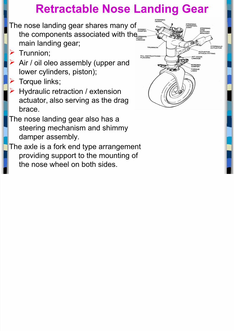
The nose landing gear shares many of
the components associated with the
main landing gear& Trunnion&
+ir 6 oil oleo assembly !upper and
lower cylinders, piston#&
Tor%ue lin$s&
2ydraulic retraction 6 extension
actuator, also serving as the drag
brace.
The nose landing gear also has a
steering mechanism and shimmydamper assembly.
The axle is a for$ end type arrangement
providing support to the mounting of
the nose wheel on both sides.
%etractable #ose Landing Gear
Cessna Citation 'ose 7anding 8ear

8/20/2019 5-1 Landing Gear
http://slidepdf.com/reader/full/5-1-landing-gear 59/63
g
+ssembly " Components

8/20/2019 5-1 Landing Gear
http://slidepdf.com/reader/full/5-1-landing-gear 60/63

8/20/2019 5-1 Landing Gear
http://slidepdf.com/reader/full/5-1-landing-gear 61/63
<. (od, steering
3. =am nut
. 5olt and nut assembly
4. Steering bellcran$
>. 5ushing, steering arm
-. 1or$?. 5olt, washer, nut, @ cotter
pin
A. Cap, air valve
B. 5ody, air valve
<. Safety wire
<<. Cap bolt @ washer
<3. (oller, aligner guide
<. 5olt, washer, nut @ cotter
pin
<4. 5rac$et, aligner
<>. Spring, inner
<-. +rm, steering
<?. Spring, outer
<A. 5olt, washer, nut @ cotter pin
<B. 7in$, upper
3. (od, piston
3<. 5olt, washer, nut, @ cotter pin33. 7in$, lower
3. *heel
34. Tire
3>. 2ousing, strut
3-. Shimmy dampener
3?. 5olt, washer, nut, @ cotter pin
3A. 5rac$et, shinny dampener
3B. 5olt, washer, nut @ cotter pin
. =am nut
<. (od end bearing
3. Drag lin$, lower
. 5olt, washer, nut @ cotter pin
4. 5olt, washer, nut @ cotter pin
>. Drag l in$, upper
-. 5olt @ nut assembly?. 5olt, washer, and nut
A. =am nut
B. Spring, downloc$
4. 2oo$, downloc$
4<. (od, actuator
43. Cylinder, hydraulic
4. +rm, spring
44. 9ngine mount
4>. +rm spring
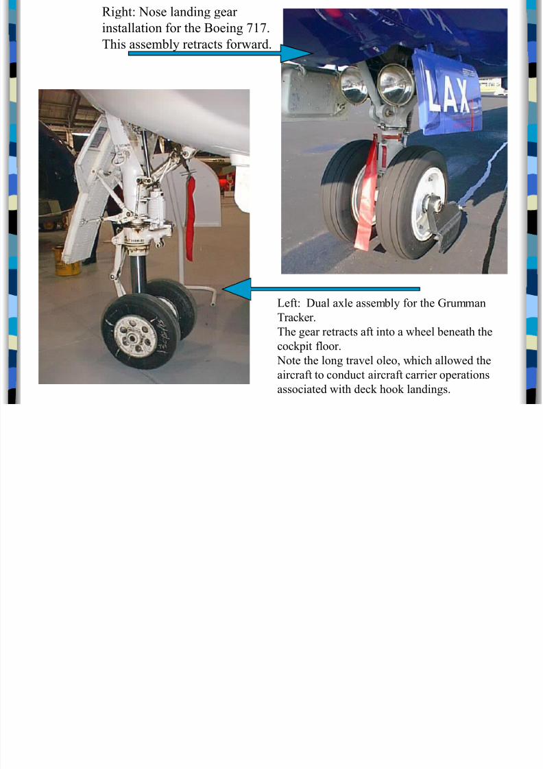
Right: Nose landing gear
installation for the 9oeing *
8/20/2019 5-1 Landing Gear
http://slidepdf.com/reader/full/5-1-landing-gear 62/63
installation for the 9oeing *.
!his assembly retrats forward.
Left: Dual a$le assembly for the Grumman
!raer.
!he gear retrats aft into a wheel beneath the
opit floor.
Note the long tra)el oleo, whih allowed the
airraft to ondut airraft arrier operations
assoiated with de hoo landings.

8/20/2019 5-1 Landing Gear
http://slidepdf.com/reader/full/5-1-landing-gear 63/63