4th e-mobility stakeholder forum -...
TRANSCRIPT

#eMSF2016@eMobilityForum
4th E-MOBILITY STAKEHOLDER FORUM
BEGOÑA GALINDO
“Low energy passenger comfort systems
based on the joule and peltier effects”

About AIMPLAS

About AIMPLAS

Agenda
o JOSPEL Fact Sheet – what is JOSPEL?
o Objectives
o JOSPEL Concept
o Expected results
o Partners Involved
o More information


Objectives
Increase engine efficiency
Reduce car weight
Improve battery efficiency
Improve energy consumption
JOSPEL
Ways of increasing distance range of an electric vehicle:

Objectives

Concept
Joule Heating (or resistive heating):▫ Process by which the passage of an electric current through a conductor
releases heat.
▫ The amount of heat release is proportional to the square of the current.
Electrodes
connection Voltage on

Concept Joule Heating (or resistive heating):
▫ Conductive sheets

Concept Joule Heating
Conductive sheets
Sheet calibration in the lab

Concept Joule Heating
Conductive fabrics
• Performances:• Fabrics area: 500 cm2 (DinA4) – 1000 cm2 (DinA3) different geometries.• Power range: 30 W (DinA4) – 60 W (DinA3)• Voltage: 12V, up to 48V• Temperature increase: ~50ºC (in less than two minutes)

Concept
Peltier cells technology:
▫ When an electric current flows through a circuit made from two
different metals, heat is given off at the upper junction and
absorbed at the lower.
▫ This occurs because the electrons flow from high to low density,
causing a cooling effect.
▫ The heat flow between the junctions was found to be proportional
to the electric current

Expected results

Partners


#eMSF2016@eMobilityForum
4th E-MOBILITY STAKEHOLDER FORUM
Merging eRoaming and Smart Charging? Our approach at Hubject
Hubject GmbH, Christian Hahn

The growing use of auxiliaries on-board of vehiclesdoes have a strong impact on energy consumption. Reducing this impact is crucial in saving energy, allowing EVs to perform better and to increase theirrange.
Moreover, IT tools can help implementing efficientsmart charging strategie
SCOPE OF THE SESSION

Hubject in a Nutshell
20 employees
8 nationalities and 14 fluent languages
More than 200 international partners
Partners in more than 16 countries all
over Europe
B2B focus
Scalable business model
International focus
Core market: Europe
Hubject was founded during the
Green eMotion project with the
clear vision, to enable
interoberability by enabling the
access to all charing stations in
EURoep for all customers
Founded in March 2012 by six
pioneering companies in the field
of eMobility based in Berlin
(EUREF-Campus)
Founding companies are: BMW
Group, Bosch, Daimler, EnBW, RWE
and Siemens
WHERE DID HUBJECT COME
FROM?
FACTS &
FIGURES:
BUSINESS
MODEL:

EASY ACCESS TO CHARGING INFRASTRUCTURE EVERYWHERE
Easy and at every charge point regardless of the operator

Merchant
(or ATM)
Acquiring
bank
Merchants’
bank
Issuing bank
Customers’
bank
ELEKTROAUTO-
FAHRER
Cardholder

A BRIEF EVOLUTION OF eROAMING
SCALABILITYLOW HIGH
OFFLINE/ MANUAL DIGITAL/ REAL TIMEM2M COMMUNICATION
Single CPO Backend
„Inhouse-Roaming“
Whitelist or multi-
client CPO platform
Open integrated
eRoaming platform
Integrated IT- &
business framework
eROAMING APPROACH
Bilateral Whitelist
Roaming
Static POI & whitelist
exchange
METHODOLOGY
Bilateral Roaming
via Roaming
platform
Technical alignment,
whiltelists/ real-time

EUROPEAN EMOBILITY MARKET = HETEROGENEOUS SYSTEMS
European energy markets are working with different schemas all over Europe
Regulatory framework is also completely different (f.E. German B2C are able to choose their energy supplier freely, but they are not able to do in other countries)
The emobility sector as a convergence sector of different industries, also has no clear European technology and regulatory framework yet
Different emobility market models are in pilot phases or early productive stages
A rising number of EVs forces changes in short time, to reduce take outs and instability issues in electricity grids

Aggreg-
gator
Distributed system operator (DSO)
Charge
point
operator
(CPO)
Emobility
Service
provider
(EMP)
Energy
Supplier
(ES)
Complex market structure in every country
More complex structure in Europe
Some market roles have to rely on scales – so smart charging is also a question of numbers
Harmonization is not as easy as it looks – who is taken the lead (Energy Industry, eMobilityindustry …)
DIFFERENT ROLES IN EMOBILITYbased on the German market, but the same applies for other markets
Roaming
Platform
Meter Operator Meter Data
Manager

REALIZATION OF CHARGING PLANS SUPPORTS SMART CHARGING
Possibilities with ISO15118-1:
Automatic authentication (Plug ‘n Charge) with certificate handling; EIM
Controlling charging process
Controlling of a DC off-board charger
(Re-) Scheduling of a charge profile according to user’s need, grid capacity, and power availability
Providing sales tariff(s)
Provide electronic signed meter receipt
Integrated information security
Energy feedback (future edition 2)
Communication based on PLC (HomePlug Green PHY) or wireless
Aufbau und Betrieb ROOT CA
Bestandteil des aktuellen Lösungsportfolios von Hubject
Aggregator:
Hubject als Clearing House zwischen OEM, CPO und MO
Abgleich von Provisioning Zertifikat zu Contract-Zertifikat
Betrieb Sub CA durch Hubject:
Hubject als Zertifikatsvergabestelle für: OEMs, MOs & CPOs (insb. als Enabling-Technologie)
Zertifizierung und Rezertifizierung von Sub CAs
Bestandteil des aktuellen Lösungsportfolios von Hubject
2a
1
0
0
OCSP Server:
Aufbau und Betrieb eines Online OCSP Servers2b
Provisioning Service:
Aufbau und Betrieb eines Provisioning Service
für die Existenz mehrere Root CAs
!3 Provisioning Service
OCSP Server
Operation Sub CA and
creating certificates
Aggregator/ ClearingHouse
Certification of Sub-CAs
Establishing Root CA
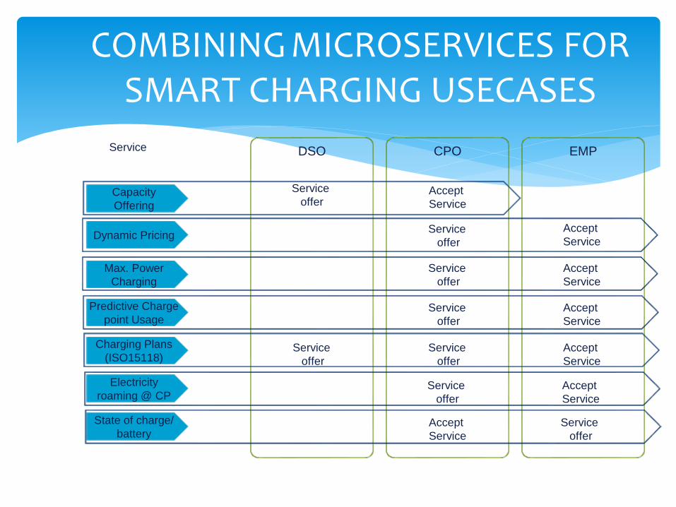
COMBINING MICROSERVICES FOR SMART CHARGING USECASES
Max. Power
Charging
Dynamic Pricing
Predictive Charge
point Usage
Charging Plans
(ISO15118)
Electricity
roaming @ CP
Capacity
Offering
State of charge/
battery
Service
Service
offerAccept
Service
Service
offer
Accept
Service
DSO EMPCPO
Service
offer
Accept
Service
Service
offer
Accept
Service
Service
offer
Accept
Service
Service
offer
Service
offer
Accept
Service
Service
offer
Accept
Service


#eMSF2016@eMobilityForum
4th E-MOBILITY STAKEHOLDER FORUM
EV Smart charging & enhancing energy management
Users and stakeholders design: co-creation is the key

EV Smart charging & enhancing energy management
OR HOW TO
Approach to real zero emissions vehicles ANDOPTIMISE electric grid and charging infrastructure

EV Smart charging & enhancing energy management
1. Reduce car energy consumption
• Car dessign (weight, size, dynamics, regeneration…)
[ kWh/100 km]• Reduction of periferics energy
consumption (aircon, lights…)
OEMs & TIER RANGE COMPETITION http://www.technologicvehicles.com/
• Less car use (rebound effect) • Driving style• Route planning considering energy• Peripherics usage• PHEVs behaviour in urban areas
USERS COACHING & ITC
Car efficiency
Users behaviour

EV Smart charging & enhancing energy management
2. Cleaner and more efficient charging
Stakeholders collaboration
Smart charging infraestructure • Mechanisms for load shifting(adjusting power to grid needs)
• Reservation and information• Intelligent load balancing for
multiplug stations• Bidirectional charging interface and
metersTECHNOLOGY CHALLENGE
• Attractive /dynamic tariffs for lowdemand charging
• Users behaviour• Increase renewable energy share• Car-infraestructure-operator
communications: reservation, information, operation
• Regulations

EV Smart charging & enhancing energy management
http://www.technologicvehicles.com/
Car efficiency
Users behaviour Stakeholders collaboration
Smart charging infraestructure

Our methodology

Some examples:
• Electric Vehicle Intelligent Charging innovationproject
• LIVE Platform for the promotion of sustainablemobility in Barcelona and Catalonia region

EVIC project:
• Control of the electric grid loading and EV use through energy demand management.
• Geographical distribution of EV fleets and their updated power needs.
• Maxim profit and minimum energetic impact
• New bussiness models associated
• Partners:
• Financed by:

EVIC project:
Project structure:

EVIC project:
Users requirements
1. Private EV user2. EV fleet manager3. Charging Operator4. Communications
manager

EVIC project:
Visualisation

LIVE Platform:
Excelent Public Administration
12
Disruptive technology Common public/privateinterests
Need for collaboration of all actors of the value chain
PUBLIC-PRIVATE PLATFORM (PPP)
Competitive green industry
Informed andparticipative citizens/users

LIVE Platform:
13
What is LIVE?
LIVE Platform is a public-private platform open to all those organisations related withsustainable and electric mobility with the common objective of developing cooperativeprojects, policies, new bussiness models and a knowledge network.
Objectives
1. Foster strategic and cooperative electromobility projects in Barcelona and Catalonia region.
2. Coordination between different governmental initiatives.
3. Support private sector transition to green economy, new bussinessmodels and job generation.
Director Members
oCollaborator Members

LIVE Platform: PLANNED ACTION 2016
Improvement of EV driving experience through ITS
• Analisis of EV users experience or “customer journey”
• Identify pain points.
• Open challenge to support digital services ideas development
Supported by SEAT


#eMSF2016@eMobilityForum
4th E-MOBILITY STAKEHOLDER FORUM
ENHANCING ENERGY MANAGEMENT
IN AN E-BUSJuhani Laurikko – VTT, Finland

Agenda
o Comparing Topologies for ICE and e-Busses
o Energy Balance of an e-Bus
o How to Save Energy?
o The Impact of HVAC
o Advanced Auxiliary Management
o Summary

Topology of Busses
On the outside, both ICE-driven and electric bussescan be quite similar, but…
ICE-BUS E-BUS

Topology of an ICE Bus
Auxiliaries are run by 24V or direct mechanical drive by the ICE
Heating is applied by waste heat from the ICE
TRANS-MISSION
DIESEL ENGINE
CHASSIS EL
WHEELS
WHEELS
BUS CHASSIS
CANBUS
AUX1
GPS
CO
MP
R1
PU
MP
ALTERNATOR
AUX224V
BATTERY
HEATEXH
DRIVERINTERFACE
AC COMPR2

Topology of an eBus (Basic)
All chassis auxiliaries are run by 24V electricity

Rolling resistance; 14,9 %
Air drag; 4,4 %
Inverter, electric motor and
driveline; 10,6 %Air compressor; 3,3 %
Steering pump; 1.8 %
Mechanical brakes; 1,9 %
24V auxiliaries; 0.7 %
Battery losses (on cycle); 3,5 %
Charger losses; 6,3 %
Battery losses (on charging); 1,7 %
Other charging losses (temp.
contr., BMS, etc.); 6,6 %
Distribution of Total Grid Energy (12.5 kWh)Braunschweig cycle, 12 400 kg
Data from a non-commercial, light-weight prototype bus
34%
16% 11%
29%

Improving Energy Efficiency (1)
Increase system & component efficiency of:
Mechanical driveline
Power electronics
Charger(s)
BMS

Improving Energy Efficiency (2)
Decrease driving energy needs: Decrease vehicle mass (lightweight chassis)
Decrease rolling resistance (tyres & bearings)
Decrease on-board auxiliary energy needs Decrease need to use mechanical brakes by maximising
regenerative braking
Decrease chassis auxiliary energy need & use, with intelligent management systems

Topology of an eBus (Advanced)
Auxiliaries are run by 24V electricity or with high voltage
All auxiliaries are run individually, according to the current need

Challenging Weather Conditions

Challenging Weather Conditions

We Need Lots of HVAC!

HVAC (10 kW); 32,2 %
Rolling resistance; 18,2 %Air drag; 5,4 %
Inverter, electric motor and driveline;
12,9 %
Air compressor; 4,1 %
Steering pump; 2,2 %
Mechanical brakes; 2.3 %
24V auxiliaries; 0,8 %
Battery losses (on cycle); 4,3 %
Charger losses; 7,6 %
Battery losses (on charging); 2,1 %
Other charging losses (temp. contr., BMS,
etc.); 8,0 %
Distribution of Total Grid Energy (18 kWh)Braunschweig cycle, 12 400 kg
Data from a non-commercial, light-weight prototype bus
Adding a 10 kWHVAC device, adds powerconsumptionby 44%

HVAC (10 kW); 32,2 %
Rolling resistance; 18,2 %Air drag; 5,4 %
Inverter, electric motor and driveline;
12,9 %
Air compressor; 4,1 %
Steering pump; 2,2 %
Mechanical brakes; 2.3 %
24V auxiliaries; 0,8 %
Battery losses (on cycle); 4,3 %
Charger losses; 7,6 %
Battery losses (on charging); 2,1 %
Other charging losses (temp. contr., BMS,
etc.); 8,0 %
Distribution of Total Grid Energy (18 kWh)Braunschweig cycle, 12 400 kg
Data from a non-commercial, light-weight prototype bus
23%
32%
13%
22%
9%
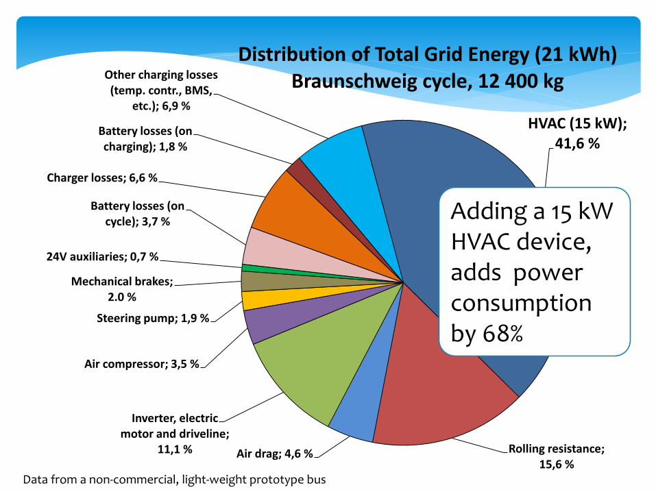
HVAC (15 kW); 41,6 %
Rolling resistance; 15,6 %
Air drag; 4,6 %
Inverter, electric motor and driveline;
11,1 %
Air compressor; 3,5 %
Steering pump; 1,9 %
Mechanical brakes; 2.0 %
24V auxiliaries; 0,7 %
Battery losses (on cycle); 3,7 %
Charger losses; 6,6 %
Battery losses (on charging); 1,8 %
Other charging losses (temp. contr., BMS,
etc.); 6,9 %
Distribution of Total Grid Energy (21 kWh)Braunschweig cycle, 12 400 kg
Data from a non-commercial, light-weight prototype bus
Adding a 15 kWHVAC device, adds powerconsumptionby 68%

HVAC (15 kW); 41,6 %
Rolling resistance; 15,6 %
Air drag; 4,6 %
Inverter, electric motor and driveline;
11,1 %
Air compressor; 3,5 %
Steering pump; 1,9 %
Mechanical brakes; 2.0 %
24V auxiliaries; 0,7 %
Battery losses (on cycle); 3,7 %
Charger losses; 6,6 %
Battery losses (on charging); 1,8 %
Other charging losses (temp. contr., BMS,
etc.); 6,9 %
Distribution of Total Grid Energy (21 kWh)Braunschweig cycle, 12 400 kg
Data from a non-commercial, light-weight prototype bus
20%
42%
11%
19%
8%

Decrease HVAC Energy Needs
Decrease HVAC needs by:
Using heat pump technology to enhance HVAC
Improving system efficiency of HVAC
Decreasing radiation influx by shades/tinting
Increasing air circulation in cabin
Decreasing air exhange while boarding/alighting(”air scarf” or cabin-type of bus stops with HVAC)

Improved low
floor isolation Improved temperature
distribution & air
circulation, human
experience of climate
Less glass
surface versus
good visibility
and appealing
exterior
Integrated
thermal energy
storages or
heat sinks
Controlled
door opening
vs. easy
access
Improved
door sealing
Optimised control
for auxiliaries,
including full
electrification
Improved efficiency
of HVAC devices
Auxiliaries, design & control
Thermal management, active
Thermal management, passive
Insulated and/or
tinted windows
Photovoltaic
panels on roof

https://www.alibaba.com/product-detail/air-conditioner-bus-shelter-prefab-bus_577903173.html
Bus stop with HVAC
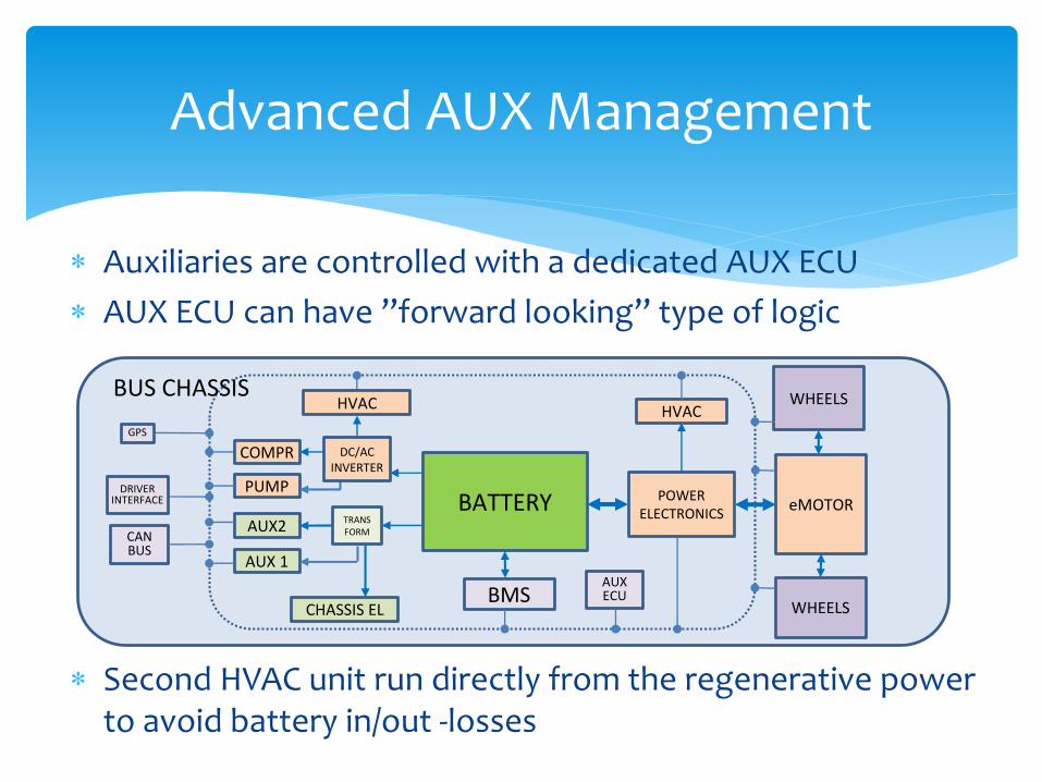
Advanced AUX Management
Auxiliaries are controlled with a dedicated AUX ECU
AUX ECU can have ”forward looking” type of logic
Second HVAC unit run directly from the regenerative powerto avoid battery in/out -losses
BATTERY eMOTORPOWER
ELECTRONICS
BMS
AUX2
AUX 1
CHASSIS EL
WHEELS
WHEELS
CANBUS
HVAC
AUX ECU
GPS
DRIVERINTERFACE
BUS CHASSIS
PUMP
COMPR
HVAC
TRANSFORM
DC/ACINVERTER

22
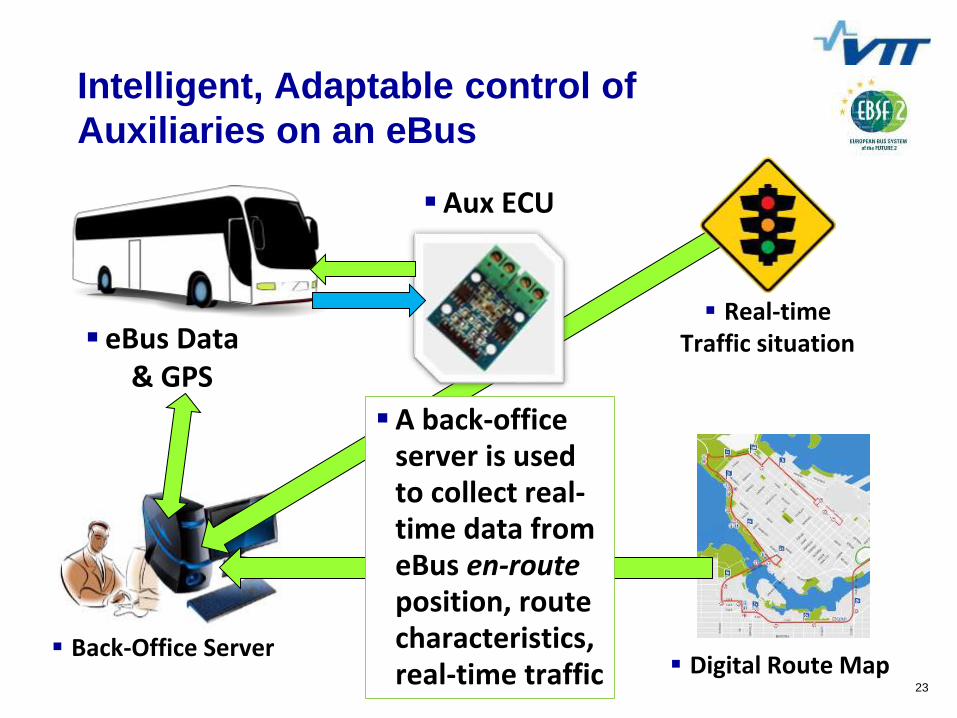
eBus Data & GPS
Intelligent, Adaptable control of
Auxiliaries on an eBus
Aux ECU
On-boardAuxiliaries
Running of the on-boardauxiliaries is controlled byAux ECU
Data is usedfrom buschasssis and aux status to decide runningstrategy, but…
23
eBus Data & GPS
Back-Office Server Digital Route Map
Real-timeTraffic situation
Aux ECU
A back-officeserver is usedto collect real-time data fromeBus en-routeposition, routecharacteristics, real-time traffic
Intelligent, Adaptable control of
Auxiliaries on an eBus

24
eBus Data & GPS
Back-Office Server Digital Route Map
Real-timeTraffic situation
Aux ECU
On-boardAuxiliaries
A back-officeserver calculatesthe optimisedrunning status for each auxsystem or itscomponent
Feeds Aux ECU with this info in real-time via data link
Intelligent, Adaptable control of
Auxiliaries on an eBus

25
eBus Data & GPS
Back-Office Server Digital Route Map
Real-timeTraffic situation
Aux ECU
On-boardAuxiliaries
Strategy is based on bothmomentaryand predictiveinformation, as the systemprovides alsoinfo about the ”foreseeablefuture”
Intelligent, Adaptable control of
Auxiliaries on an eBus

SMART ENERGY MANAGEMENT IS ESSENTIAL FOR e-BUSSES!
o Limited battery capacity (or high price & weight) is a great challenge to e-bus autonomy & energy balance
o Addressing all energy consuming systems is necessary
o Improvements can come either by using more efficient systems, or by …
o Decrease the need to use energy, and especially by …
o Employing an intelligent energy management system
