4sion.rs/download/gliki/manualgp400.docx · web viewtemperature controller operation manual before...
TRANSCRIPT

TEMPERATURE CONTROLLER
OPERATION MANUAL
Before using please check whether range, input and output match your requirement.
Thank you for using our microprocessor temperature controller. We have obtained CE certification (LDV: D/N EN61010-1; EMC EN 55 022 1994/A1: 1995/A2: 1997, EN 61 000-3-2: 1995/ -3-3: 1995, EN 61 000-4-2: 1995/ -4-3: 1996/ -4-5: 1995/ -4-6: 1996/ -4-8: 1993/ -4-11: 1996/ EN 50 204: 1995) for all our products since January 2002. We have also computerized our QC process and testing to provide high quality standard, low price and high functionality of our products.

1. Front Panel Instruction
1.1 DISPLAYPV:Process value,4 digit display (red color)SV:Setting value,4 digit display (green color)
1.2 LEDOUT1 :Output 1,green colorOUT2 :Output 2,green color
1

AT :Auto Tuning,yellow colorPRO :Program,yellow color --- Only available for PFP models.AL1 :Alarm 1,red colorAL2 :Alarm 2,red colorAL3 :Alarm 3,red colorMAN :Manual,yellow color
*Note: When error occurs, the MAN will light up, and will reset output percentage to zero.
1.3 KEYSET :MODE & SET key
:SHIFT key
:DOWN key (Setting value –1, -10, -100, -1000)
:UP key (Setting value +1, +10, +100, +1000)A/M :Auto/Manual key.
Automatic :The output percentage is determined by internalcalculation.
Manual _The output percentage is determined by setting OUTLmanually at User Level.
2 Auto tuning2.2 Once AT is set YES,auto tuning is to be performed.2.3 After auto tuning is finished, a new set of PID parameter is
generated internally to replace the existing PID parameter.Auto tuning allows the controller to automatically adjust the PID parameter. It is used when temperature control is not accurate enough.
2.4 ATVL=auto tuning offset,and it will be deduced from SV
(it can prevent over shoot during auto tuning)SV-ATVL=Auto-tuning value,ATVL=auto tuning offsetEx.SV=200℃,ATVL=5,Auto tuning point is at 195℃During auto tuning, PV value will oscillate around 195 .℃Hence PV will not go over 200 .℃* In programmable model,ATVL means Auto-tuning point
2

2.5 Auto tuning failure Possible Cause 1: ATVL is too big. (If not sure,set ATVL=0)
Possible Cause 2: System time is too long.(Set PID parameter individually)
3. Error information
DISPLAY DESCRIPTION
IN1E Open circuit of main control sensor.
* ADCF A/D converter failed.
* CJCE Cold junction compensation failed.IN2E Open circuit of sub control sensor.UUU1 PV exceeds USPL.NNN1 PV under LSPL.UUU2 Input signal of sub control exceeds the upper limit.NNN2 Input signal of sub control under the lower limit.
* RAMF RAM failed.INTF Interface failed.AUTF Auto tuning failed.
NOTE:If the “*” marked error comes up the controller needs repair.Please send it to the nearest sales office or retail dealer.
4. Operating flow4.1 LEVEL 1 (User Level)
3

4.1.1 Press the SHIFT KEY ( ) to change the parameters. If the SHIFT KEY is pressed,the first digit begins blinking. Press the UP KEY( ) or DOWN KEY( ) to increase or decrease the value of the digit,then press the SHIFT KEY( ) again to go to the next digit. As all the digit are written,press SET KEY to enter the value.
4.1.2 SET KEY also has the function of changing MODEs,if the SET KEY is pressed,the display shows the next MODE.
4.1.3 Press SET KEY for 5 sec. the display goes to LEVEL 2,and do the same to return LEVEL 1.
4.1.4 If any key were not pressed for 1 minute,the display would go to LEVEL 1.4.1.5 Press A/M KEY twice will go to LEVEL 1,no matter where it is.4.1.6 If OUTL set "0",it means the controller has no output,
4.2 LEVEL 2 (PID Level)press SET key for 5 seconds to enter Level 2
4

4.3 LEVEL 3 (INPUT Level)When LCK=0000 , press SET key and SHIFT KEY for 5 seconds to enter LEVEL
5

3
6

7

4.4 LEVEL 4 (SET Level)When LCK=1111 , press SET key and SHIFT KEY for 5 seconds to enter Level 4. There are SET 0.1 to SET 9.4 for use.
4.4.1 Display:
4.4.2 Function of SETs
SET Function SET Function1.1 OUTL 5.1 CLO2,CHO21.2 AT 5.2 CLO3,CHO31.3 AL1 5.3 RUCY,WAIT,SETA1.4 AL2 5.4 IDNO,BAUD2.1 AL3 6.1 SVOS2.2 ANL1,ANH1,DP 6.2 PVOS2.3 LSPL,USPL 6.3 UNIT2.4 ANL2,ANH2 6.4 SOFT3.1 ALD1 7.1 CASC3.2 ALT1 7.2 OUD3.3 ALD2 7.3 OPAD3.4 ALT2 7.4 HZ4.1 ALD34.2 ALT34.3 HYSA4.4 CLO1,CHO1
8

SET Function Remarks8.1 0=No repeat
Programmable Model Only1=Program repeat
8.2 0=No power failure1=With power failure
8.3 0=Start from 01=Start from PV
9.3 TRS SVAuxiliary Output Use
9.4 TRS PV0.3 0=No Remote SV
1=Remote SV When SET8.3=1 (The programmable controller will initiate the SV value to be the
current PV value.) The controller will be more energy efficient, and also decreases the time needed to achieve the desired SV value. The remaining time left to reach the SV value will be shown in the parameter “TIMR”. Hence the time of countdown is related to the PV value, not related to segment setting.
Please don't operate SET 8.4,otherwise the controller's process will be in confusion.
If SET8.4 is set to “1”, the controller will enter into “Single Display” mode, the PV LED will not display any values. The SV LED will display both the parameter value and the setting value alternately as shown in the diagram below.
To rectify the problem please press the SHIFT KEY ( ) and change the setting value to “XXX0”.
4.4.3 FUNCTION OF LCKLCK=0000,It can enter Level 3 ( press SET + for 5 sec.)LCK=1111,It can enter Level 4 ( press SET + for 5 sec.)LCK=0100,It can enter Level 1 & 2 and change their parameters.LCK=0110,It can enter Level 1 & 2 but change Level 1 parameters only.LCK=0001,It can enter Level 1 only and change SV only.
9

LCK=0101,It can't change any parameters except LCK.
4.5 PROGRAM LEVEL (to be ordered)
10

4.5.1 This program has 2 patterns,each pattern contains 8 segments.
11

4.5.2 TerminologiesPattern :A program consists of some steps.Step :A Ramp status + a Soak status.Ramp status:The status with changing SV.Soak status :The status with fixed SV.
4.5.3 Operating1. "KEY" function (no changing parameter)
(RUN) :To start program procedure,PRO in panel flicker.(HOLD) :To suspend program procedure,PRO in panel will stop
flicker but light. + SET(JUMP) :To jump segment.
+ SET (RESET):To reset program procedure,PRO in panel will be "off".
2. Alarm Function:If ALD1 to be set “07”(*refer to the selection,p.14~15),AL1 to be set “2”(AL1=2,it means alarm in segment 2 end),ALT1 to be set “00.10”(alarm time 10 sec.).* In this case,when program proceeds to segment 2 end,ALM1 relay will be on 10 sec.
3. END function:This controller doesn’t have END order, so if program procedure are less than 8 segments, please set segment’s out = 0, then this program will end in last set segment. Otherwise,it will proceed 8 or 16 segments.
4. Linking Function:PTN=1 proceed pattern 1,contains 8 segments.PTN=2 proceed pattern 2,contains 8 segments.PTN=0 linking proceed pattern 1 and 2 totally 16 segments.
(set PTN1 and PTN2 at first,then set PTN=0)5. Other function(*refer to LEVEL 4)
SET 8.1=1 program repeat.SET 8.2=0 No power fail function.SET 8.2=1 with power fail function
(if power suspend,the controller will keep memory)SET 8.3=0 program start from 0.SET 8.3=1 program start from PV.
12

5. INPUT5.1 Input selection (INP1)
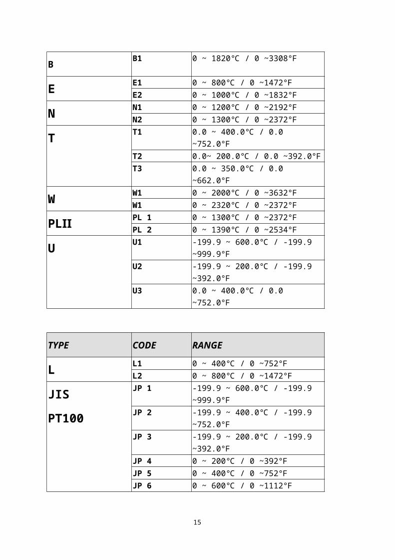
TYPE CODE RANGE
K
K1 0.0 ~ 200.0 / 0.0 ~392.0℃ ℉ K2 0.0 ~ 400.0 / 0.0 ~752.0℃ ℉ K3 0 ~ 600 / 0 ~1112℃ ℉ K4 0 ~ 800 / 0 ~1472℃ ℉ K5 0 ~ 1000 / 0 ~1832℃ ℉ K6 0 ~ 1200 / 0 ~2192℃ ℉
J
J1 0.0 ~ 200.0 / 0.0 ~392.0℃ ℉ J2 0.0 ~ 400.0 / 0.0 ~752.0℃ ℉ J3 0 ~ 600 / 0 ~1112℃ ℉ J4 0 ~ 800 / 0 ~1472℃ ℉ J5 0 ~ 1000 / 0 ~1832℃ ℉ J6 0 ~ 1200 / 0 ~2192℃ ℉
R R1 0 ~ 1600 / 0 ~2912℃ ℉ R2 0 ~ 1796 / 0 ~3216℃ ℉
S S1 0 ~ 1600 / 0 ~2912℃ ℉ S2 0 ~ 1796 / 0 ~3216℃ ℉
B B1 0 ~ 1820 / 0 ~3308℃ ℉
E E1 0 ~ 800 / 0 ~1472℃ ℉ E2 0 ~ 1000 / 0 ~1832℃ ℉
N N1 0 ~ 1200 / 0 ~2192℃ ℉ N2 0 ~ 1300 / 0 ~2372℃ ℉
T T1 0.0 ~ 400.0 / 0.0 ~752.0℃ ℉ T2 0.0~ 200.0 / 0.0 ~392.0℃ ℉T3 0.0 ~ 350.0 / 0.0 ~662.0℃ ℉
W W1 0 ~ 2000 / 0 ~3632℃ ℉ W1 0 ~ 2320 / 0 ~2372℃ ℉
PLⅡ PL 1 0 ~ 1300 / 0 ~2372℃ ℉ PL 2 0 ~ 1390 / 0 ~2534℃ ℉
U U1 -199.9 ~ 600.0 / -199.9 ~999.9℃ ℉ U2 -199.9 ~ 200.0 / -199.9 ~392.0℃ ℉U3 0.0 ~ 400.0 / 0.0 ~752.0℃ ℉
13

TYPE CODE RANGE
L L1 0 ~ 400 / 0 ~752℃ ℉ L2 0 ~ 800 / 0 ~1472℃ ℉
JIS
PT100
JP 1 -199.9 ~ 600.0 / -199.9 ~999.9℃ ℉ JP 2 -199.9 ~ 400.0 / -199.9 ~752.0℃ ℉JP 3 -199.9 ~ 200.0 / -199.9 ~392.0℃ ℉JP 4 0 ~ 200 / 0 ~392℃ ℉ JP 5 0 ~ 400 / 0 ~752℃ ℉ JP 6 0 ~ 600 / 0 ~1112℃ ℉
DIN
PT100
DP 1 -199.9 ~ 600.0 / -199.9 ~999.9℃ ℉ DP 2 -199.9 ~ 400.0 / -199.9 ~752.0℃ ℉DP 3 -199.9 ~ 200.0 / -199.9 ~392.0℃ ℉DP 4 0 ~ 200 / 0 ~392℃ ℉ DP 5 0 ~ 400 / 0 ~752℃ ℉ DP 6 0 ~ 600 / 0 ~1112℃ ℉
JIS
PT50
JP.1 -199.9 ~ 600.0 / -199.9 ~999.9℃ ℉ JP.2 -199.9 ~ 400.0 / -199.9 ~752.0℃ ℉JP.3 -199.9 ~ 200.0 / -199.9 ~392.0℃ ℉JP.4 0 ~ 200 / 0 ~392℃ ℉ JP.5 0 ~ 400 / 0 ~752℃ ℉ JP.6 0 ~ 600 / 0 ~1112℃ ℉
AN1 AN1 -10 ~ 10mV / -1999~9999AN2 AN2 0 ~ 10mV / -1999~9999AN3 AN3 0 ~ 20mV / -1999~9999AN4 AN4 0 ~ 50mV / -1999~9999AN5 AN5 10 ~ 50mV /-1999~9999
*The initial set in factory is “K2” without any certain requirement
14
6. ALARM6.1 Alarm function selectionCODE DESCRIPTION INHIBIT00 / 10 None 01 Deviation high limit alarm YES11 Deviation high limit alarm NO02 Deviation low limit alarm YES12 Deviation low limit alarm NO03 Deviation high / low limit alarm YES13 Deviation high / low limit alarm NO04 / 14 Deviation high / low limit range alarm NO05 Absolute value high limit alarm YES15 Absolute value high limit alarm NO06 Absolute value low limit alarm YES16 Absolute value low limit alarm NO07 Segment end alarm
(use for program model only)-
17 Program run alarm(use for program model only)
-
08 System error alarm-on -18 System error alarm-off -09 -19 On delay timer alarm -
Note:the word “INHIBIT” means that alarm does not work at the first
time.
15

6.2 Alarm action description
16

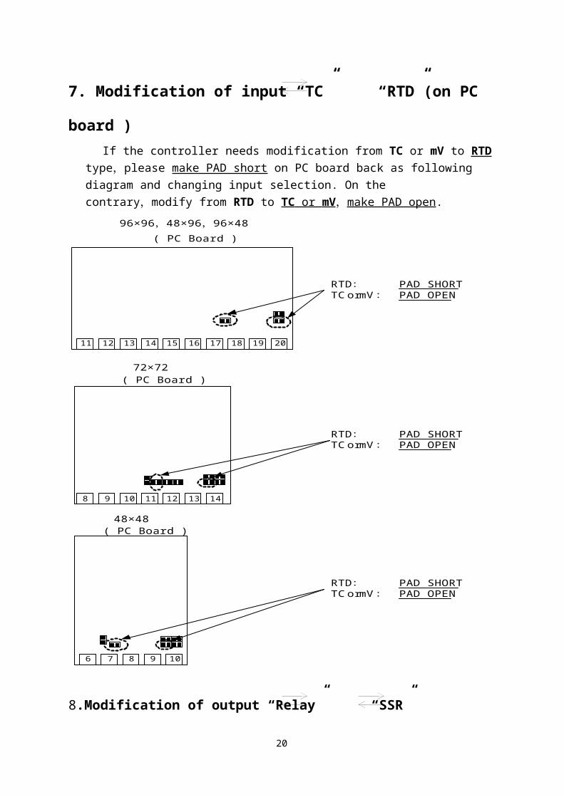
7. Modification of input “TC” “RTD”(on PC board )If the controller needs modification from TC or mV to RTD type,please make
PAD short on PC board back as following diagram and changing input selection. On the contrary,modify from RTD to TC or mV ,make PAD open.
8.Modification of output “Relay” “SSR” “4~20mA”It just needs to change a module at the same position,and modify parameter
CYT1 in LEVEL 2 .
12 13 14 15 16 17 18 19 20
( PC Board )96×96 48×96 96×48, ,
RTD: PAD SHORTTC or mV: PAD OPEN
8 9 10 11 12 13 14
11
( PC Board )72×72
RTD: PAD SHORTTC or mV: PAD OPEN
6 7 8 9 10
( PC Board )48×48
RTD: PAD SHORTTC or mV: PAD OPEN
17

9. Modification of output
“HEAT/ALARM” “HEAT/COOL” (on PC board)
18

10. Modification of INPUT:0~1V,0~5V,0~10V,mA
10.1 Hardware part:96×96,48×96,96×48 72×72 48×48
INPUT ( + ) PIN 17 PIN 11 PIN 7INPUT ( - ) PIN 20 PIN 14 PIN 10
0~20mA (INP1=AN4):(R3 use 100Ω,R5 use 2.4Ω, S3&S5 SHORT)4~20mA (INP1=AN5):(R3 use 100Ω,R5 use 2.4Ω, S3&S5 SHORT)0 ~ 1V (INP1=AN4):(R1 use 2KΩ,R4 use 100Ω,S1&S4 SHORT)0 ~ 5V (INP1=AN4):(R2 use 10KΩ,R4 use 100Ω,S2&S4 SHORT)1 ~ 5V (INP1=AN5):(R2 use 10KΩ,R4 use 100Ω,S2&S4 SHORT)0 ~ 10V (INP1=AN4):(R3 use 22KΩ,R4 use 100Ω,S3&S4 SHORT)2 ~ 10V (INP1=AN5):(R3 use 22KΩ,R4 use 100Ω,S3&S4 SHORT)
19
10.2 Software part (Calibrate input)
20

21

11. Special Function Description:11.1 LEVEL 4 (Set Level)
11.1.1 Second input mode (FP MODEL ONLY )INP2=0 None INP2=1 10~50mV / 4~20mA / 1~5V / 2~10VINP2=2 0~50mV / 0~20mA / 0~5V / 0~10V*Second Input is for Remove SV function, but the PFP model`s SV can only be controlled by the program, so INP2=0 is not applicable.
11.1.2 Output modeOUTY=0 Single OutputOUTY=1 Double OutputOUTY=2 NoneOUTY=3 Motor ValveOUTY=4 1φSCR (Single Phase Control)OUTY=5 3φSCR (Three Phase Control)
22

11.2 RAMP & SOAK (Only Applicable for FP MODEL)11.2.1 RAMP:I. Please set “SET2.1=1”(Display AL3),”SET4.1=1” (Display ALD3) II. ALD3=9 at INPUT Level III. RAMP menu will be displayed (replace AL3)
11.2.2 SOAK:I. ALD1 / ALD2=19II. AL1 / AL2 will be display
11.2.3 Example:SV=100℃,RAMP=10.00 ( /min)℃ ,AL1=00.10 min,PV=25℃
23

11.3 REMOTE SV (Only applicable for FP MODEL)11.3.1 Hardware must be mounted11.3.2 Set INP2 to1 or 2 (calibration use ANL2,ANH2)11.3.3 SET 0.3=0 means local SV11.3.4 SET 0.3=1 means remote SV from Input 2 channel 11.4 Alarm Time ALT1/ALT2/ALT3 description (FP MODEL ONLY)1. ALT1=0 means flicker if AL1 is on2. ALT1=99.59 means alarm if AL1 is on3. ALT1=00.01 ~ 99.58 means AL1 is on delay timer
(* use for large EMI affect controller)11.5 Renew function “HYSM” “SETA”
11.6 Function SET811.6.1 SET8.1=0 None
SET8.1=1 program repeat (PFP model ) 11.6.2 SET8.2=0 Non (PFP only)
SET8.2=1 Power failure access11.6.3 SET8.3=0 Zero start (PFP only)
SET8.3=1 PV start (PFP only)11.6.4 SET8.4=0 None
SET8.4=1 display will be transferred to single display (Don’t set this Bit) *SET8=0000 can return double display
24

11.7 Function SET911.7.1 SET9.1=0 None
SET9.1=1 PV / SV switching(use for single display so please don’t set this Bit.)
11.7.2 SET9.2=0 None SET9.2=1 PFP models :Timer change from H.M to M.S
11.7.3 SET9.3=0 NoneSET9.3=1 Transmission SV
11.7.4 SET9.4=0 None SET9.4=1 Transmission PV
11.8 SET011.8.1 SET0.1=0 None
SET0.1=1 TTL communication SV output11.8.2 SET0.2=0 None
SET0.2=1 Rate for AL3 (ALD3=0) (see Application 1,P.25)11.8.3 SET0.3=0 None
SET0.3=1 Remote SV11.8.4 SET0.4=0 Motor Valve close = “b” out
SET0.4=1 Motor Valve close = “a” out (Don’t care)11.9 WAIT at INPUT Level
WAIT=0 means “no wait”WAIT≠0 means “wait”
25

12.Panel cut & Outline Dimension:12.1 Panel Cut Dimension(Units:mm)
A B C DFP400 44.5+0.5 44.5+0.5 65 70FP600 90.5+0.5 44.5+0.5 111 70FP700 68.5+0.5 68.5+0.5 89 94FP800 44.5+0.5 90.5+0.5 65 116FP900 90.5+0.5 90.5+0.5 111 116
12.2 Outline Dimension (Units:mm)
E F G HFP400 50 50 17 80FP600 96 50 17 80FP700 74 74 17 80FP800 50 96 17 80
26

FP900 96 96 17 80
Application
App1. TTL communication:SV output & RATE function Open RATE function (use for slave)11.10 Open Rate :SET0.2=111.11 Open AL3 :SET2.1=111.12 Open ALD3:SET4.1=111.13 ALD3=0 at INPUT Level11.14 Slave SV = ( RATE ÷9999)×master SV Example:
27

App2. Single Phase Control (for SCR module) Available Models:FP900 / PFP900,FP700 / PFP700 Data Change: OUTY=4
CLO1=0,CHO1=4500 if use for resistance loadCLO1=0,CHO1=4000 if use for inductor load
28

App3. Single Phase Control (for TRIAC module) Available Models:FP900 / PFP900,FP700 / PFP700 Data Change: OUTY=4
CLO1=0,CHO1=4500 if use for resistance loadCLO1=0,CHO1=4000 if use for inductor load
29

App4. Three Phase Control Available Models:FP900 / PFP900 Data Change: OUTY=5
CLO1=0,CHO1=4500 only if use for resistance load
30

App5. Single Phase Zero Control Available Models: FP900 / PFP900,FP700 / PFP700
FP400 / PFP400 Data Change: OUTY=0
CYT1=1
31

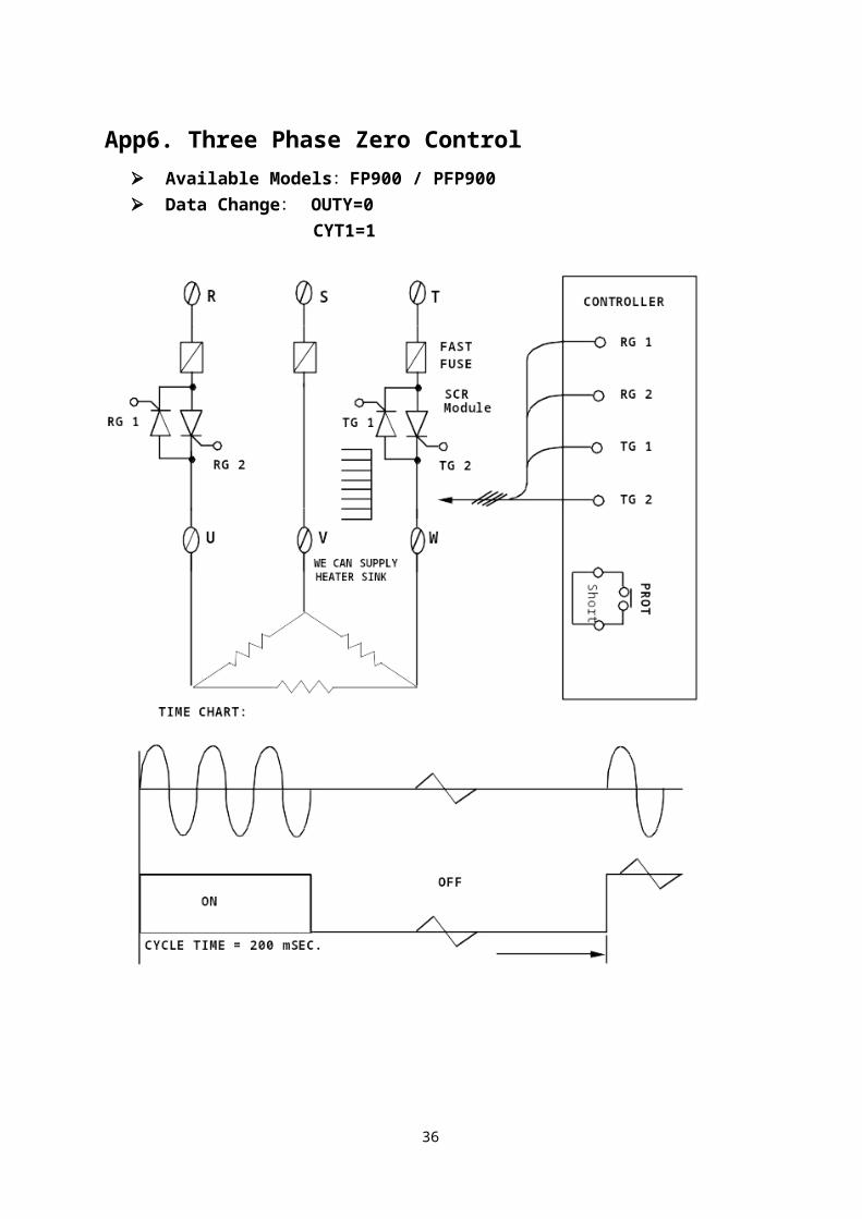
App6. Three Phase Zero Control Available Models:FP900 / PFP900 Data Change: OUTY=0
CYT1=1
32

App7. Motor Valve Control Available Models: FP900 / PFP900,FP700 / PFP700
FP800 / PFP800,FP600 / PFP600FP400 / PFP400
Data Change: OUTY=3CYT1=1 ~ 100sec.
33

( Manufacturing default setting “5” sec.)RUCY=5 ~ 200 sec.
1. CYT1 is the cycle time of Open / Close2. RUCY is the running time of motor valve 0 ~ 100%
App8. RS485 Communication
34

App9. RS232 Communication
35
36