4re vehicle installation instructions - watchguard...
TRANSCRIPT

4RE Vehicle Installation
Instructions
WatchGuard Video WGD00085 REV B1

Vehicle Installation Instructions
WGD00085 REV B1 Page 2
About this document This document is not meant as an exclusive blueprint for any particular vehicle, but general instructions for a 4RE DVR installation. This instruction manual errs on the side of more information for those persons/installers who may be new to the installation process. If there is an issue or question pertaining to a particular vehicle make and model, please direct your questions to the WatchGuard Video Customer Service Department at 1-800-605-MPEG (6734).
Contents 4RE Vehicle Installation Instructions ............................................................................................................ 1 About this document .................................................................................................................................... 2 Standard Parts included for a wireless installation ...................................................................................... 3 Optional parts for installation ....................................................................................................................... 3 Recommended Tools .................................................................................................................................... 4 Document Conventions: ............................................................................................................................... 4 Before installing the 4RE system in a vehicle................................................................................................ 5 Quick Overview of Installation ...................................................................................................................... 6 Starting Your Installation: ............................................................................................................................. 6
Mounting the Wireless Antenna to the Vehicle ................................................................................... 7 Mounting the Bullet Radio .......................................................................................................................... 10 Connecting the Power Cable to the Vehicle Battery .................................................................................. 11 Connecting the External Inputs Cable ......................................................................................................... 15
Ignition – White Wire .......................................................................................................................... 15 Emergency Lights – Blue with White Stripe ........................................................................................ 16 Siren – Pink and Green Wires ............................................................................................................. 17 Auxiliary – Solid Blue Wire .................................................................................................................. 18 Brake Input – Black Wire with White Stripe ....................................................................................... 19 Chassis Ground – Yellow Wire ............................................................................................................ 20 Power Over Ethernet (PoE) Adapter – Orange and Brown ................................................................. 21
PoE Ethernet Cable Connections ................................................................................................................ 21 MDC/MDT Configuration (Optional) ........................................................................................................... 22 PoE Switch ................................................................................................................................................... 22 Radar Interface Cable (Optional) – Purple/Black/Gray connector ............................................................. 23 GPS Antenna (Optional) .............................................................................................................................. 23 Display and Front Combo Camera – HDMI/HDMI mini .............................................................................. 23 Front HD camera HDMI/HDMI mini ............................................................................................................ 23 Rear analog camera HDMI/BNC and molex power..................................................................................... 23 Mounting the Remote Display Control Panel ............................................................................................. 24 Wireless Microphone .................................................................................................................................. 24 Cabin Microphone....................................................................................................................................... 25 Front HD Combination Camera ................................................................................................................... 27 Test Functions of DVR ................................................................................................................................. 30

Vehicle Installation Instructions
WGD00085 REV B1 Page 3
Standard Parts included for a wireless installation
Qty Part Number Description
1 WGA00480-100 4RE, HD DVR, (2nd Generation)
1 WGA00370 4RE, Remote Display Control Panel
1 WGA00437 Camera Assembly, 4RE, HD Front, Glass mount
1 WGP01760-100 Camera, Infrared Analog, WMv.1, 2-Pin Connector
1 WGA00475-KIT Hi-Fi Microphone Kit
Transmitter
Cradle
10 ‘Antenna Cable
Clips
1 WGA00428-001 4RE In-Car 802.11n Wireless Kit (Bullet, Antenna, PoE)
1 WGP01475 Bracket, HiFi Microphone, Universal
1 WGP01443-001-KIT Bracket Kit, 4RE, DVR, Universal
1 WGA00420 Bracket Kit, 4RE, Display, Standard RAM 2"
1 WGP362 GPS Antenna, Magnetic Mount
1 WGD00085-KIT Kit, 4RE DVR Installation Kit, Wireless
1 WGD00089-KIT Kit, 4RE In-Car Video System User Guide
1 WGP01394-001 Wi-Fi Vehicle Antenna Mount, NMO, Drill 3/4" Hole,
1 WGP01506-KIT Cable Assembly, DV-1C/4RE, Power/Input, R/A, 24'
1 WGP412 Cabin Microphone - 7'
1 WGP412-300 Cabin Microphone Extension Cable - 12'
1 WGP01832 4RE, Cable, HDMI, Port 2, Backseat Camera, 16’
1 WGP01829-004 4RE, Cable, HDMI, Front Cam, Straight, 15'
1 WGA00382 4RE, Cable, HDMI, Display/Combo Cam, Straight, 15'
Optional parts for installation
Qty Part Number Description
1 WGA480-600 4RE, HD DVR & Mezzanine, (2nd Generation)
1 WGA00475-CHARGEKIT Hi-Fi Microphone Desktop Charger Kit 1
1 WGP01507-004 4RE, Cable, HDMI, Display/Combo Cam, R/A, 15'
1 WGP01829-004 4RE, Cable, HDMI, Front Cam, Straight, 15'
1 WGP01688 4RE, Cable, Mezzanine, VGA to 4-Analog Cam, 7'
1 WGP01803 4RE, Cable, HDMI, Port 2, Backseat Camera, 2-Pin 16'
1 WGA00348 Camera Assembly, 4RE, HD Front/Cabin Combo, Glass Mount
1 WGA00391 4RE, Power Over Ethernet / Gigabit 4-port Switch
1 WGA00351-200 Dual Microphone Splitter, 3-Port, HiFi Mic and Trinus
1 N/A 4RE Display Bracket (varies on model of vehicle)
1 WGP01487-KIT Bracket Kit, 4RE, DVR, Console Faceplate, 2"

Vehicle Installation Instructions
WGD00085 REV B1 Page 4
Recommended Tools Drill and bits
o ¾ inch bit for antenna mounting o Philips bits
Coarse sandpaper 60 or 80 Grain
10-30 feet of 16-20 gauge primary wire for extending input cable connections if necessary
Wire strippers
Wire cutters
Various wrenches and sockets (one unusual open ended wrench needed is 24mm or 15/16’’)
Pliers
Utility Knife
Torx screwdrivers or bits sizes T20, T15, T10
1/16” hex screwdriver or Allen head wrench
Electrical Tape and/or heat shrink tubing
Zip ties
Document Conventions: The following conventions are used within this document.
Note: Notices provide useful supplemental information that is pertinent to the task or item being described.
Caution: Cautions describe very important information that, if ignored, could result in damage to the system, inoperability or degradation in function, or injury to personnel.
Warning: Warnings describe critical information that should not be ignored.

Vehicle Installation Instructions
WGD00085 REV B1 Page 5
Before installing the 4RE system in a vehicle Begin by ensuring that you have received all the parts for the 4RE system. If you have any missing or damaged parts please call WatchGuard Video Customer Service at 1-866-384-8567.
1. Ensure that the mounting brackets for the DVR, display screen, and wireless microphone bracket are the correct types for your specific vehicle(s).
2. Gather all necessary tools for the installation. 3. Use the 4RE installation poster as a reference guide for the overview of the installation
a. If you did not receive an installation poster, you can download a copy from our website: http://watchguardvideo.com/support/ or call 1-866-384-8567.
4. Determine if any of the cable lengths will be too short. If a cable is too short please contact customer service for a different cable length.
5. Prepare the vehicle for installation. a. Remove any old video equipment (if applicable) b. Determine installation locations for the 4RE DVR, Bullet wireless radio, wireless
antenna, GPS antenna, etc. c. Determine all wire connection points before starting the installation, i.e. vehicle battery
location, overhead input, brake input, auxiliary input, etc.

Vehicle Installation Instructions
WGD00085 REV B1 Page 6
Quick Overview of Installation 1. Gather all tools and materials 2. Mount Radio antenna and route cable 3. Configure and mount Radio Bullet 4. Install external inputs/power cable 5. Route cables for:
a. Camera(s) b. Wireless Microphone c. Cabin Microphone d. Touch display e. Ethernet
6. Install optional cables (GPS and Radar) 7. Install optional switch for MDC/MDT application 8. Mount PoE connector 9. Mount touch display bracket 10. Mount Wireless Microphone 11. Connect and mount camera(s) 12. Connect cables to DVR
13. Insert fuse 14. Turn on DVR and test functions (Also see Quick Reference Guide to test functions)
Note: If using a Mezzanine card (additional ports) the “WIRELESS MIC 2” and “AUX MIC” ports are not used. The firmware does not activate these ports. Instead use the Dual Mic splitter.

Vehicle Installation Instructions
WGD00085 REV B1 Page 7
Starting Your Installation:
Mounting the Wireless Antenna to the Vehicle Find a suitable location for the antenna and a route for the antenna cable. Typically the antenna is mounted on the roof or trunk of the vehicle. The antenna cable is then routed to where the Wireless Radio will be placed. WatchGuard Video recommends that you configure the Wireless Radio before mounting it into the vehicle.
Caution: There are 2 different types of antenna mounts – a thru-hole antenna (NMO mount) which requires drilling a ¾” hole in the metal of the vehicle OR a magnetic mount which does not require drilling a hole. WatchGuard Video recommends using the NMO mount antenna if possible for better signal strength.
Determine where you will mount the antenna. The following installation example demonstrates mounting procedure in a Chevrolet Tahoe Police Package Vehicle. If you have a different vehicle the installation may vary.
1. You can access the roof of the vehicle through a rear seat dome light or by removing the headliner. [Figure 1 and 2]
Figure 1 Figure 2

Vehicle Installation Instructions
WGD00085 REV B1 Page 8
2. Drill a ¾ inch hole for the antenna cable. [Figure 5]
Figure 3 Figure 4 Figure 5
3. After the hole is made, sand the paint off the interior metal around the hole to ensure a good ground. [Figure 6]
4. Remove the NMO exterior nut. 5. Ensure that the antenna mount ridges come in contact with the bare metal. [Figure 7]
Figure 6 Figure 7
6. Feed the antenna cable connector end first through the ¾ inch exterior hole in the roof of the vehicle. [Figure 8 and 9]
7. Tilt the antenna mount and guide it into the hole and center the flange in the drilled hole. [Figure 10]
Figure 8 Figure 9 Figure 10

Vehicle Installation Instructions
WGD00085 REV B1 Page 9
8. Re-attach the NMO nut with the o-ring facing down to create a seal. [Figure 11] 9. Tighten the nut with a 24mm or 15/16’’ open end wrench ensuring that the mount stays
centered in the hole and that the mount does not turn and kink the cable. [Figure 12]
Warning: Do not use a Channel lock pliers as it could damage the NMO nut. Instead use an open end wrench. Damaging the NMO nut could result in unreliable wireless signal.
Figure 11 Figure 12 Figure 13
10. Route the antenna connector to where the Bullet radio will be mounted – make sure to leave
enough slack to avoid kinks. 11. Attach the antenna connector to the Bullet radio. [Figure 14]
Figure 14
Warning: Never plug in the PoE connector (Ethernet connection) and power up the Bullet radio without an antenna attached as it can damage the radio.

Vehicle Installation Instructions
WGD00085 REV B1 Page 10
Mounting the Bullet Radio
For Instructions on how to configure the Bullet with the wireless network see the document: Evidence Library Administrative Guide
Warning: In order to configure the Bullet it must be attached to a POE power adapter and the antenna before connecting to your computer. Make sure you attach your Ethernet cable from your laptop to the port on the POE adapter labeled “DVR” or you may damage your laptop.
The Bullet should be mounted in a way that the LED lights can be easily viewed for diagnostic purposes. Common mounting locations are:
Glove compartment
On the front of the Cage
Inside the center console There is no mounting hardware included with the Bullet radio. It is typical to use zip ties to attach the radio to your desired location.
To see if the Bullet is working properly, check the LED lights on the side of the device.
1. Power LED: The power LED will be lit, if the Bullet has power. 2. Connectivity LED: This light will blink if it is communicating with the DVR 3. Signal LED’s: These 4 LED’s will light up if the Bullet is “Associated” with the Access
Point. In most cases the vehicle will not be near the Access Point during the time of installation. Red is low signal, and each LED to the right is a better strength.
To verify the Bullet is connected properly, see Page 29.

Vehicle Installation Instructions
WGD00085 REV B1 Page 11
Connecting the Power Cable to the Vehicle Battery The power/external inputs cable looks like the following:
Figure 15
1. Route the power cable to the vehicle battery.
Note: For the Chevrolet Tahoe with a dual battery configuration, use the passenger side battery if possible. The passenger battery is considered an auxiliary battery for electronics.
2. When routing the power cable, use factory firewall holes and grommets if possible.
There are usually several factory firewall ports giving access to the engine bay. Use the one that is the easiest to access. Ford Crown Victoria – factory grommet is on the front foot-well on the passenger side. Dodge Charger – battery is located in the trunk. The power cable can be routed down the passenger side rail and under the rear seat in the factory wiring channel that runs back to the battery. Chevrolet Impala – use the driver door grommet and go through to the inside of the fender to the front of the engine bay. Chevrolet Tahoe – the following example is from a Chevrolet Tahoe – a small grommet hole is behind the factory fuse block located on the driver’s side foot-well. Remove the rubber gasket, slit a small hole in the grommet and pass the power cable through to the engine bay. [Figure 16]

Vehicle Installation Instructions
WGD00085 REV B1 Page 12
Figure 16 Figure 17
3. Pull the power cable to the battery. 4. Pull excess cable out past the battery side of the firewall (leave some slack for a drip loop).
Figure 18
5. Also pull the Chassis ground extension wire to the vehicle battery at this time, if possible. It is easier to route the chassis ground cable with the rest of the cables. (The extension cable is not included, use an additional cable for this function)
6. You can either wind up and tie off the excess cable or cut off the excess cable where necessary. 7. Strip / remove approximately 3-5” of the external black sheathing and the foil Mylar shielding
from the power cable.
Grommet access through firewall

Vehicle Installation Instructions
WGD00085 REV B1 Page 13
8. Strip back ½ inch on the red, black and additional Chassis ground cable. [Figure 19]
Figure 19
9. Twist the black ground, the un-insulated silver drain wire, and chassis ground wires together [Figure 20] and crimp on a ring terminal to be attached to the battery negative ground post. [Figure 21]
Figure 20 Figure 21
10. Crimp the red positive wire to the inline fuse holder using a butt-splice connector and a ring terminal to the end of the inline fuse holder to be attached to the positive battery post. [Figure 22]
Figure 22

Vehicle Installation Instructions
WGD00085 REV B1 Page 14
11. Connect the positive and negative wires to the appropriate vehicle battery posts. [Figure 23]
Figure 23
12. Route the power harness inside the engine bay in such a manner that it will not interfere with the vehicle.
Note: Leave the 7.5 amp fuse out until the DVR is ready to be turned on.
Positive (+) side

Vehicle Installation Instructions
WGD00085 REV B1 Page 15
Connecting the External Inputs Cable Before connecting the input cable it is necessary to know the wiring scheme for connecting the external inputs cable. All the inputs generally require positive 8-12 volts of power to activate the corresponding device. When a particular input senses a positive voltage on its wire, the selected input will turn on or become active. Connect the wires from the input cable using butt splices where possible. This ensures a good connection and consistent voltage.
Ignition – White Wire The ignition wire senses whether the ignition is on or off. The white wire needs to connect to a feed that provides positive 12 volts when the vehicle is ON and 0 volts when the vehicle is OFF. There is a fuse link with a 1 amp fuse provided to connect the ignition feed and the ignition sense wire from the inputs cable. [Figure 24] Several common factory sources for ignition power are as follows: Crown Victoria – pink wire inside the gray rectangular police package wiring harness located under the passenger side dashboard. Dodge Charger – pink wire with purple stripe inside the white rectangular police package wiring harness inside the center console. Chevrolet Impala – pink or yellow wire in the factory police package wiring harness located under the passenger side carpeting. There are several options available for configuring how the system reacts to the vehicle ignition signal. To change these configurations refer to the document: Evidence Library Administrator Guide.
Figure 24

Vehicle Installation Instructions
WGD00085 REV B1 Page 16
Emergency Lights – Blue with White Stripe The Emergency Lights input should connect to a positive 12 volt switched power source that provides voltage when the overhead lights are activated. [Figure 25]
Note: Some emergency light manufacturers use negative 12 volt or ground triggers. In those cases an additional relay may need to be incorporated into the wiring scheme to provide positive 12 volt power to the input wire.
Figure 25

Vehicle Installation Instructions
WGD00085 REV B1 Page 17
Siren – Pink and Green Wires The siren input wire consists of two wire connections – the green wire is connected to the siren speaker ground feed and the pink wire is connected to the positive siren speaker feed. When the siren is activated then the siren input will sense voltage. [Figure 26]
Figure 26

Vehicle Installation Instructions
WGD00085 REV B1 Page 18
Auxiliary – Solid Blue Wire Depending on the installation this input wire may or may not be used. The input should be connected to a device that provides positive 12 volt switched power to be used as an alternate trigger. For example, the input can be connected to a shotgun mount electric release button or a K-9 electric kennel door release. [Figure 27]
Figure 27
Vehicle Installation Instructions
WGD00085 REV B1 Page 19
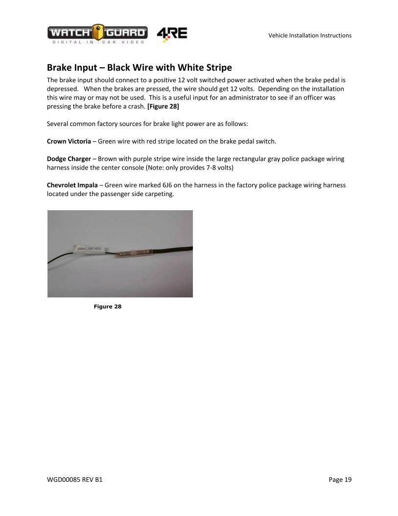
Brake Input – Black Wire with White Stripe The brake input should connect to a positive 12 volt switched power activated when the brake pedal is depressed. When the brakes are pressed, the wire should get 12 volts. Depending on the installation this wire may or may not be used. This is a useful input for an administrator to see if an officer was pressing the brake before a crash. [Figure 28] Several common factory sources for brake light power are as follows: Crown Victoria – Green wire with red stripe located on the brake pedal switch. Dodge Charger – Brown with purple stripe wire inside the large rectangular gray police package wiring harness inside the center console (Note: only provides 7-8 volts) Chevrolet Impala – Green wire marked 6J6 on the harness in the factory police package wiring harness located under the passenger side carpeting.
Figure 28

Vehicle Installation Instructions
WGD00085 REV B1 Page 20
Chassis Ground – Yellow Wire It is imperative that the chassis ground wire is grounded properly. The DVR is sensitive to ground loops and any stray voltage that may be running through the frame ground of the vehicle. Ensure that the chassis ground is connected to a good bare metal ground lug or bare metal screw/nut/bolt. Test the wire with a volt meter (or multi-meter) and ensure there is no stray voltage. The Chassis Ground cable should not have any more than +/- .025 volts. Anything more will cause the DVR to be unpredictable is operation. In Figure 29 the voltage reading is TOO HIGH. Figure 29
Warning: Improperly grounded chassis ground wire connections will result in unpredictable DVR operation and performance.
Note: WatchGuard Video recommends that the Chassis ground always be grounded to the Negative (ground) post on the vehicle battery.
External Ground
Chassis Ground

Vehicle Installation Instructions
WGD00085 REV B1 Page 21
Power Over Ethernet (PoE) Adapter – Orange and Brown The assembly consists of a POE adapter which provides power from the DVR to the Bullet Radio and two Ethernet cables that connect from the DVR to the Bullet radio. The orange wire is positive 12 volt power and the brown wire is ground. Strip back the insulation on both wires and insert the appropriate wires into the labeled holes on the POE adapter and tighten the screws down with a small flat or Philips screwdriver. [Figure 30a]
Figure 30a
PoE Ethernet Cable Connections There are 2 Ethernet cables included in the DVR installation kit. The first Ethernet cable connects from the DVR to the PoE Adapter (labeled “DVR” on the POE adapter). The second Ethernet cable connects from the PoE adapter to the Bullet radio (labeled “Radio” on the POE adapter). [Figure 31]
Warning: Be sure to plug the Ethernet cables into the correct ports on the PoE adapter. If the cables are plugged in backwards the Ethernet port on the DVR will be damaged!
Figure 31

Vehicle Installation Instructions
WGD00085 REV B1 Page 22
MDC/MDT Configuration (Optional)
Note: 1 additional Ethernet cables will be needed (this should be included with the MDC package).
PoE Switch When the configuration of the DVR uses a MDC/ MDT (Laptop connection to DVR), a PoE Switch is needed. The PoE switch allows additional connections to the DVR via Ethernet. Connect an Ethernet cable (CAT5E or CAT6) from the PoE switch to the Laptop Ethernet port (RJ45). [Figure 32] In the figure only the DVR and Wireless Radio are connected. Use any of the numbered ports for the Laptop connection.
Figure 32
Warning: Be sure to plug the Ethernet Cable into the correct ports on the PoE Switch. If the cables are plugged in backwards the Ethernet port on the switch will be damaged!
Note: If using a Docking Station, use the Ethernet port on the docking station, rather than the Ethernet port on the laptop. See docking station manufacture manual for further instructions.

Vehicle Installation Instructions
WGD00085 REV B1 Page 23
Radar Interface Cable (Optional) – Purple/Black/Gray connector The radar interface cable connects from the radar unit into the radar interface connector on the input cable. Please refer to the specific installation instructions included with the radar interface cable.
GPS Antenna (Optional) The GPS cable has a threaded antenna ferrule and should be attached to the GPS port on the back of the DVR. The antenna end has a magnetic base and may be mounted to the exterior roof, trunk, on the vehicle, or may be mounted to the dashboard of the car providing that sufficient view of the sky is available.
Display and Front Combo Camera cables – HDMI/HDMI mini
Warning: HDMI cables are very susceptible to damage and will not worked if kinked or pinched. Be very careful when installing and working around these cables.
Typically the front combo camera cable and the display cable will be run in the same vicinity. Mark one of the cables on both ends to distinguish it from the other. The standard (larger) HDMI connectors connect to the back of the DVR. Typically, the cables are run along the top of the headliner, down the A-pillar to wherever the DVR is mounted.
Note: If the HDMI cables are reversed the DVR will not be able to power up via the front panel on/off switch.
Front HD camera HDMI/HDMI mini In some installations a separate front and rear camera will be used (the DVR needs 2 cameras to function). A front HD camera can only be added to a DVR that has a REV 2 board. To see if the DVR has a REV 2 board, check the serial number for a DVR2-XXXXXX. If it has a BDVR, EDVR, then it is not compatible.
Rear analog camera HDMI/BNC The rear analog camera uses an HDMI (standard) to BNC connection to the rear camera. A rear camera can only be added to a DVR that has a REV 2 board or a Mezzanine card. If using a Mezzanine card, then there will be a VGA cable instead of the HDMI cable to the rear camera. Use the mezzanine card for installations that have more than 1 auxiliary analog camera.

Vehicle Installation Instructions
WGD00085 REV B1 Page 24
Mounting the Remote Display Control Panel Depending on the type of vehicle you have, mounting the Remote Display Control Panel will differ with each installation. Please refer to the display mounting documentation that came with your specific bracket.
Warning: Be careful when installing the back door on the display with the HDMI cable – make sure there is plenty of room for the cable and not getting pinched in the assembly. It will not work if so.
Wireless Microphone The wireless microphone can be mounted using one of two different brackets – a visor post bracket or a universal mounting bracket. Examples of mounting locations are:
Passenger visor post
Universal bracket can be mounted almost anywhere – side of the console, rear of the console, on the cage wall, etc.
The cable has a male 8 pin RJ45 on one end and a male 6 pin RJ11 on the other end. The RJ45 connects to the wireless microphone base, and the RJ11 connects into the DVR. If installing a HiFi Wireless Microphone, mount the antenna in the following orientation:
Mount the external windshield antenna(s) in the upper right hand corner of the windshield in a horizontal orientation with 2” of spacing between both the top and side of the antenna as shown below. Route the Antenna cables between the dashboard and windshield pillar.
Warning: If the Wireless Antenna is mounted vertically, then the Microphone will have VERY POOR SIGNAL STRENGTH
Mount the HiFi Base (cradle) in an area that is easily assessable to the officer.

Vehicle Installation Instructions
WGD00085 REV B1 Page 25
Cabin Microphone The cabin microphone utilizes a 3.5mm headphone style jack. The cabin microphone can be mounted anywhere in the vehicle cabin as necessary to record the audio inside the vehicle. The cabin microphone should not be mounted within 5-6 inches of the wireless microphone if possible as it can cause some interference.
Warning: Do not insert or remove the cabin microphone when the DVR is powered up. It may cause the display screen to go black and will damage the DVR. If this happens, turn off the system, fully plug in or unplug the microphone and then cycle power on the system to reset the display. This can also damage the cabin microphone port.
Front HD Camera The camera is mounted to the windshield using a rear-view mirror type windshield button. Glue the camera mounting button to the windshield using adhesive. Ensure that the button is mounted with the bevel towards the windshield and the curved edge pointing down. Route the Front Camera HDMI cable (WGP01829-004) from the DVR to the front camera (this cable has a thumb screw on each end of the cable- Figure 33e).
Note: Place the windshield button as high as possible on the windshield for a better viewing angle. See Figure 40
1. Scratch or score the mounting surface using sandpaper or similar (Fig. 6A). Clean the windshield
where the button will be attached. Glue the windshield button onto the windshield.
2. For best results let the adhesive cure for at least 1 hour mounting the camera 3. Connect the 15’ mini HDMI cable to the camera (round edge towards the back- Fig. 33b). 4. Screw down the thumb screw on the cable 5. Attach the camera to the mirror button with a Torx 20 screw driver. Ensure the screw is snug,
but not overly tight. This screw should be periodically checked to make sure it is hand tight.
Figure 33a Figure 33b
Front

Vehicle Installation Instructions
WGD00085 REV B1 Page 26
Figure 33c Figure 33d Figure 33e

Vehicle Installation Instructions
WGD00085 REV B1 Page 27
Front HD Combination Camera The combination camera is mounted on the windshield approximately one inch to the right of the rear view mirror. The camera uses a mirror button that is glued to the top of the windshield. Mount the button as high up on the windshield as possible to reduce blocked vision to the driver.
1. Scratch or light scoring the side of the button that glues to the windshield using sandpaper. [Figure 34]
No Scoring Scoring applied
Figure 34a Figure 34b
2. Clean the area where the button will be placed. 3. Place the activator solution on the windshield and on the button. 4. Allow the solution to dry for two minutes. 5. Apply the adhesive to the center of the button – usually one drop in the center of the button.
[Figure 35] Figure 35
6. Place button (round end down) on the windshield and press and hold firmly on the windshield
for one minute. 7. Let cure for at least 1 hour before installing the camera.

Vehicle Installation Instructions
WGD00085 REV B1 Page 28
Attach the camera to the Button 1. After the button has cured and set, connect the mini HDMI cable to the camera (round edge
towards the front of the camera [Figure 36-38].
Figure 36 Figure 37 Figure 38
2. Screw on the thumb screw that holds the cable in place [Figure 39]. Figure 39
3. Tighten the mounting screw with a T20 screw driver [Figure 40].
Figure 40
Note: The HDMI mini cable port on the camera has the round edge facing the front of the camera.
Front

Vehicle Installation Instructions
WGD00085 REV B1 Page 29
Rear Seat Camera – Below is an example of mounting the rear camera on a caged Crown Vic. Find the best place to install the camera in the specific vehicle (as it may vary vehicle to vehicle) In this scenario zip ties were used to secure the camera around the cage tubing ensuring that the ties are tight enough that the window frame of the cage will not close and rub against them.
Figure 41a Figure 41b
Note: Verify the correct camera orientation is set, as there is not a way to tell which side is up or down (the sticker normally is on the top, however it and the IR lights are not a proper indicator).

Vehicle Installation Instructions
WGD00085 REV B1 Page 30
Test Functions of DVR Ensure all components are connected properly by performing a few tests.
1. Connect 7.5 amp Fuse at the Battery 2. Start the vehicle and power on system by pressing the on ( ‘I’) button, if it does not start
automatically 3. Load Vehicle configuration on DVR from USB drive. 4. Ensure the display screen shows the camera feed. 5. Press MENU button on the front panel and select any button to check that the touchscreen is
working. 6. Press the Auto Zoom button on the camera to test front camera functionality. 7. Turn ON the wireless microphone, and insert the microphone in the permanent charging base.
Once the green LED light on the microphone stops flashing, the microphone has synced with the base. Pull out the microphone, and press the talk button. Ensure the wireless microphone icon appears on the screen. Go to the volume screen and under advanced menu turn up the wireless microphone volume in order to listen for the live feed through the display speakers. Press STOP to end the recording.
8. If equipped, connect and test secondary wireless microphone (see above) 9. Press the RECORD button on the front panel to start a recording. Record for at least 15 seconds.
Press STOP to stop the recording. 10. Check that all inputs are wired correctly by going to Menu>Status> Devices. Activate and verify
each input turns on: a. Emergency Lights b. Brakes c. Ignition d. Wireless Microphone
11. Turn on the secondary camera by selecting “CAMERAS” and toggling the secondary camera(s) on and off. Verify the view angle is set properly
12. Verify no connectors such as “Scotch Locks” were used. Only Crimp connections must be used 13. Test Wireless Connectivity and if available, upload video to server.
a. Check for at least 3 LED lights on the Bullet (Wireless Radio)
i. LED 1 Power – Green ii. LED 2 Connectivity – Green flashing
iii. LED 3 Low signal – Red iv. LED 4 Medium signal – Yellow v. LED 5 Good Signal – Green
vi. LED 6 High Signal – Green b. Check for Wireless Signal on the Display 1-4 bars c. If server is configured and ready, the upload icon will appear

Vehicle Installation Instructions
WGD00085 REV B1 Page 31
4RE Vehicle Installation Instructions WatchGuard Video 415 Century Parkway Allen, Texas 75013 1-800-605-6734 Toll Free Sales 1-866-384-8567 Toll Free Support [email protected]