4d systems - sparkfun electronics · 4d systems udrive-usd-g1 embedded dos micro-drive data sheet...
TRANSCRIPT
4D SYSTEMS
uDRIVE-uSD-G1Embedded “DOS micro-Drive” ModuleData Sheet
Document Date: 2nd April 2009Document Revision: 2.0
© 2009 4D Systems www.4dsystems.com.au Page 1 of 9
4D SYSTEMS
uDRIVE-uSD-G1Embedded DOS micro-Drive
Data Sheet
Description
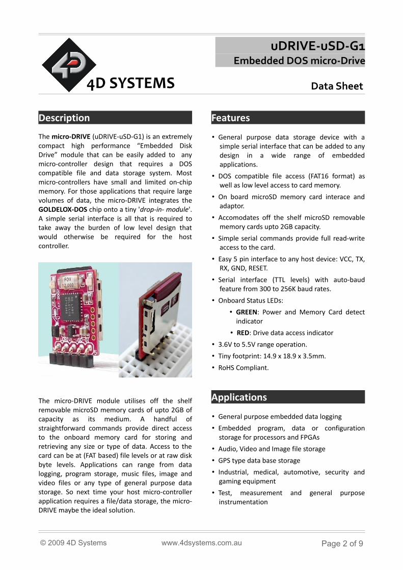
The micro-DRIVE (uDRIVE-uSD-G1) is an extremely compact high performance “Embedded Disk Drive” module that can be easily added to any micro-controller design that requires a DOS compatible file and data storage system. Most micro-controllers have small and limited on-chip memory. For those applications that require large volumes of data, the micro-DRIVE integrates the GOLDELOX-DOS chip onto a tiny 'drop-in- module'. A simple serial interface is all that is required to take away the burden of low level design that would otherwise be required for the host controller.
The micro-DRIVE module utilises off the shelf removable microSD memory cards of upto 2GB of capacity as its medium. A handful of straightforward commands provide direct access to the onboard memory card for storing and retrieving any size or type of data. Access to the card can be at (FAT based) file levels or at raw disk byte levels. Applications can range from data logging, program storage, music files, image and video files or any type of general purpose data storage. So next time your host micro-controller application requires a file/data storage, the micro-DRIVE maybe the ideal solution.
Features
• General purpose data storage device with a simple serial interface that can be added to any design in a wide range of embedded applications.
• DOS compatible file access (FAT16 format) as well as low level access to card memory.
• On board microSD memory card interace and adaptor.
• Accomodates off the shelf microSD removable memory cards upto 2GB capacity.
• Simple serial commands provide full read-write access to the card.
• Easy 5 pin interface to any host device: VCC, TX, RX, GND, RESET.
• Serial interface (TTL levels) with auto-baud feature from 300 to 256K baud rates.
• Onboard Status LEDs:
• GREEN: Power and Memory Card detect indicator
• RED: Drive data access indicator
• 3.6V to 5.5V range operation.
• Tiny footprint: 14.9 x 18.9 x 3.5mm.
• RoHS Compliant.
Applications
• General purpose embedded data logging
• Embedded program, data or configuration storage for processors and FPGAs
• Audio, Video and Image file storage
• GPS type data base storage
• Industrial, medical, automotive, security and gaming equipment
• Test, measurement and general purpose instrumentation
© 2009 4D Systems www.4dsystems.com.au Page 2 of 9
micro-DRIVE (uDRIVE-uSD-G1) Data Sheet
Table of Contents
1. Pin Configuration and Description..................................................................................................42. Host Interface...................................................................................................................................4
2.1 Physical Interface - UART..........................................................................................................42.2 Software Interface – Command Set..........................................................................................52.3 Auto-Baud Setup.......................................................................................................................52.4 Command Protocol – Flow Control...........................................................................................5
3. Powerup and Reset..........................................................................................................................54. microSD Cards – FAT16 Format........................................................................................................65. PmmC Programming - System Updates..........................................................................................66. Development and Support Tools.....................................................................................................7
6.1 PmmC Loader–Software Programming Tool ............................................................................76.2 microUSB – Hardware Programming Tool.................................................................................76.3 4D FAT Controller – Software Test Tool.....................................................................................8
7. Mechanical Details...........................................................................................................................88. Specifications and Ratings...............................................................................................................9Proprietory Information....................................................................................................................10Disclaimer of Warranties & Limitation of Liability...........................................................................10
© 2009 4D Systems www.4dsystems.com.au Page 3 of 9
micro-DRIVE (uDRIVE-uSD-G1) Data Sheet
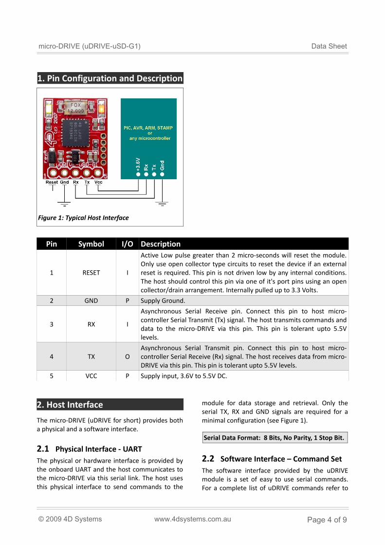
1. Pin Configuration and Description
Pin Symbol I/O Description
1 RESET I
Active Low pulse greater than 2 micro-seconds will reset the module. Only use open collector type circuits to reset the device if an external reset is required. This pin is not driven low by any internal conditions. The host should control this pin via one of it's port pins using an open collector/drain arrangement. Internally pulled up to 3.3 Volts.
2 GND P Supply Ground.
3 RX I
Asynchronous Serial Receive pin. Connect this pin to host micro-controller Serial Transmit (Tx) signal. The host transmits commands and data to the micro-DRIVE via this pin. This pin is tolerant upto 5.5V levels.
4 TX OAsynchronous Serial Transmit pin. Connect this pin to host micro-controller Serial Receive (Rx) signal. The host receives data from micro-DRIVE via this pin. This pin is tolerant upto 5.5V levels.
5 VCC P Supply input, 3.6V to 5.5V DC.
2. Host Interface
The micro-DRIVE (uDRIVE for short) provides both a physical and a software interface.
2.1 Physical Interface - UARTThe physical or hardware interface is provided by the onboard UART and the host communicates to the micro-DRIVE via this serial link. The host uses this physical interface to send commands to the
module for data storage and retrieval. Only the serial TX, RX and GND signals are required for a minimal configuration (see Figure 1).
Serial Data Format: 8 Bits, No Parity, 1 Stop Bit.
2.2 Software Interface – Command SetThe software interface provided by the uDRIVE module is a set of easy to use serial commands. For a complete list of uDRIVE commands refer to
© 2009 4D Systems www.4dsystems.com.au Page 4 of 9
Figure 1: Typical Host Interface
micro-DRIVE (uDRIVE-uSD-G1) Data Sheet
the sperate document titled 'GOLDELOX-DOS Command Set - Software Interface Specification'.
2.3 Auto-Baud SetupThe micro-DRIVE has an auto-baud feature which can automatically detect the host speed and can set its internal baud rate to operate from 300 to 256K baud. Prior to any commands being sent to the module, it must first be initialized by sending the auto-baud character ‘U’ (55hex) after any power-up or reset. This will allow the module to determine and lock on to the baud rate of the host automatically without needing any further setup. Once the uDRIVE has locked onto the host baud rate it wil respond with an ACK byte (06hex).
Auto-Bauding must be performed each time the uDRIVE is powered up or reset.
2.4 Command Protocol – Flow ControlThe Each command is made up of a sequence of data bytes. When a command is sent to the module and the operation is completed, the uDRIVE will always return a response. For a command that has no specific response the module will send back a single acknowledge byte called the ACK (06hex), in the case of success, or NAK (15hex), in the case of failure.
Commands having specific responses may send back varying numbers of bytes, depending upon the command and response. It will take the module a certain amount of time to respond, depending on the command type and the operation that has to be performed. If the uDRIVE receives a command that it does not understand it will reply back with a negative acknowledge called the NAK (15hex). Since a command is only identified by its position in the sequence of dataʻ ʼ bytes sending incorrect data can result in wildly incorrect operation.
No termination character is to be sent at the end of a command sequence, such as CR, Null, etc.
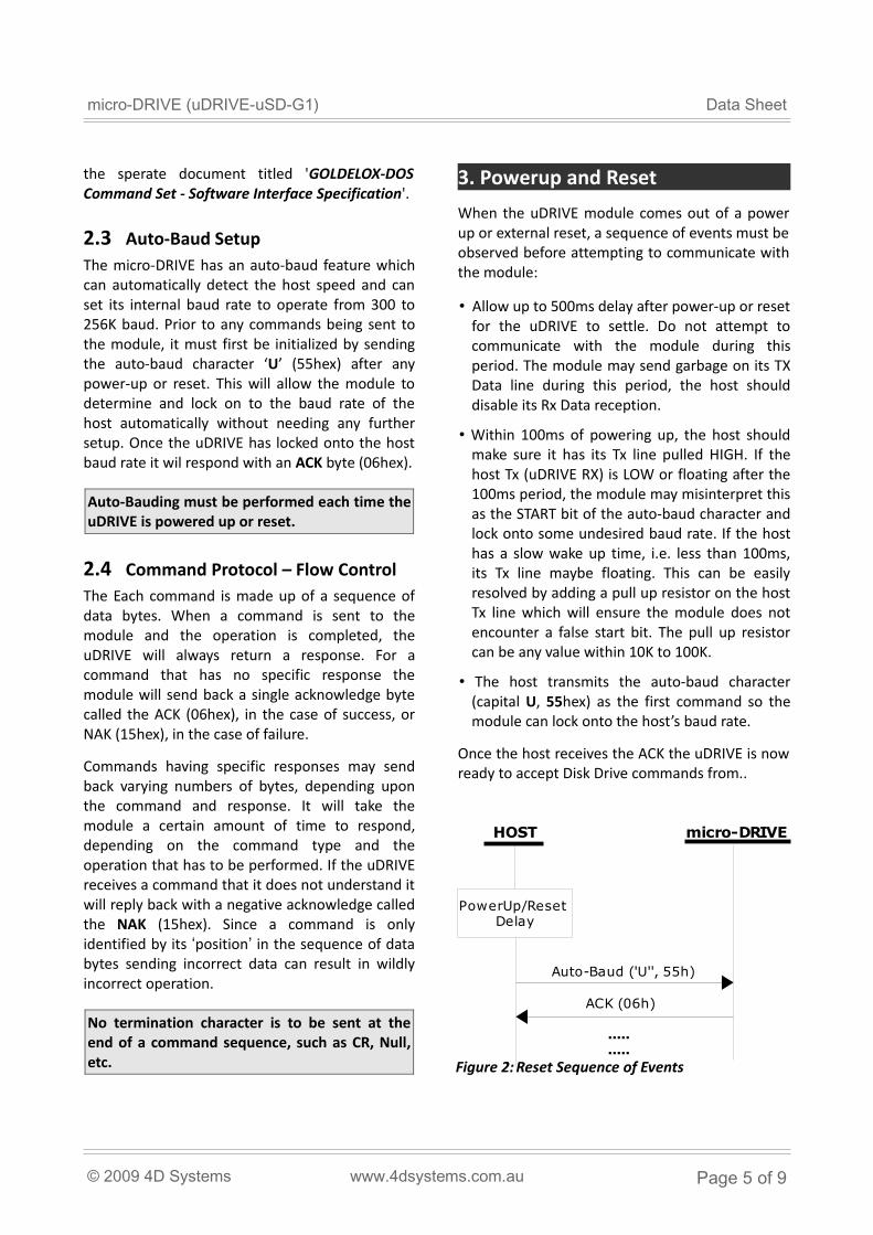
3. Powerup and Reset
When the uDRIVE module comes out of a power up or external reset, a sequence of events must be observed before attempting to communicate with the module:
• Allow up to 500ms delay after power-up or reset for the uDRIVE to settle. Do not attempt to communicate with the module during this period. The module may send garbage on its TX Data line during this period, the host should disable its Rx Data reception.
• Within 100ms of powering up, the host should make sure it has its Tx line pulled HIGH. If the host Tx (uDRIVE RX) is LOW or floating after the 100ms period, the module may misinterpret this as the START bit of the auto-baud character and lock onto some undesired baud rate. If the host has a slow wake up time, i.e. less than 100ms, its Tx line maybe floating. This can be easily resolved by adding a pull up resistor on the host Tx line which will ensure the module does not encounter a false start bit. The pull up resistor can be any value within 10K to 100K.
• The host transmits the auto-baud character (capital U, 55hex) as the first command so the module can lock onto the host’s baud rate.
Once the host receives the ACK the uDRIVE is now ready to accept Disk Drive commands from..
© 2009 4D Systems www.4dsystems.com.au Page 5 of 9
Figure 2: Reset Sequence of Events
HOST micro-DRIVE
Auto-Baud ('U'', 55h)
ACK (06h)
..... .....
PowerUp/Reset Delay
micro-DRIVE (uDRIVE-uSD-G1) Data Sheet
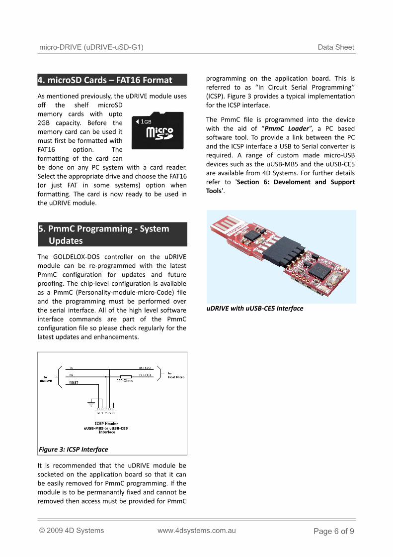
4. microSD Cards – FAT16 Format
As mentioned previously, the uDRIVE module uses off the shelf microSD memory cards with upto 2GB capacity. Before the memory card can be used it must first be formatted with FAT16 option. The formatting of the card can be done on any PC system with a card reader. Select the appropriate drive and choose the FAT16 (or just FAT in some systems) option when formatting. The card is now ready to be used in the uDRIVE module.
5. PmmC Programming - System Updates
The GOLDELOX-DOS controller on the uDRIVE module can be re-programmed with the latest PmmC configuration for updates and future proofing. The chip-level configuration is available as a PmmC (Personality-module-micro-Code) file and the programming must be performed over the serial interface. All of the high level software interface commands are part of the PmmC configuration file so please check regularly for the latest updates and enhancements.
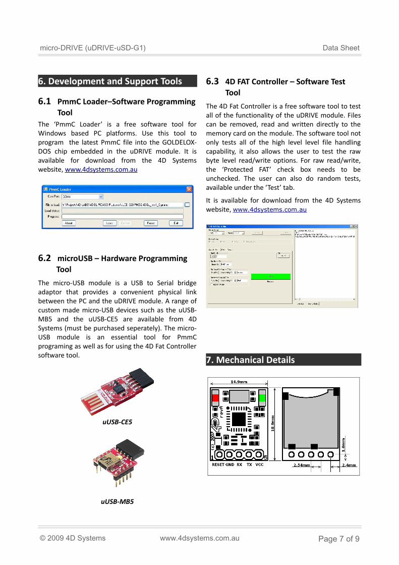
It is recommended that the uDRIVE module be socketed on the application board so that it can be easily removed for PmmC programming. If the module is to be permanantly fixed and cannot be removed then access must be provided for PmmC
programming on the application board. This is referred to as “In Circuit Serial Programming” (ICSP). Figure 3 provides a typical implementation for the ICSP interface.
The PmmC file is programmed into the device with the aid of “PmmC Loader”, a PC based software tool. To provide a link between the PC and the ICSP interface a USB to Serial converter is required. A range of custom made micro-USB devices such as the uUSB-MB5 and the uUSB-CE5 are available from 4D Systems. For further details refer to 'Section 6: Develoment and Support Tools'.
© 2009 4D Systems www.4dsystems.com.au Page 6 of 9
Figure 3: ICSP Interface
uDRIVE with uUSB-CE5 Interface
micro-DRIVE (uDRIVE-uSD-G1) Data Sheet
6. Development and Support Tools
6.1 PmmC Loader–Software Programming Tool
The ‘PmmC Loader’ is a free software tool for Windows based PC platforms. Use this tool to program the latest PmmC file into the GOLDELOX-DOS chip embedded in the uDRIVE module. It is available for download from the 4D Systems website, www.4dsystems.com.au
6.2 microUSB – Hardware Programming Tool
The micro-USB module is a USB to Serial bridge adaptor that provides a convenient physical link between the PC and the uDRIVE module. A range of custom made micro-USB devices such as the uUSB-MB5 and the uUSB-CE5 are available from 4D Systems (must be purchased seperately). The micro-USB module is an essential tool for PmmC programing as well as for using the 4D Fat Controller software tool.
6.3 4D FAT Controller – Software Test Tool
The 4D Fat Controller is a free software tool to test all of the functionality of the uDRIVE module. Files can be removed, read and written directly to the memory card on the module. The software tool not only tests all of the high level level file handling capability, it also allows the user to test the raw byte level read/write options. For raw read/write, the ‘Protected FAT’ check box needs to be unchecked. The user can also do random tests, available under the ‘Test’ tab.
It is available for download from the 4D Systems website, www.4dsystems.com.au
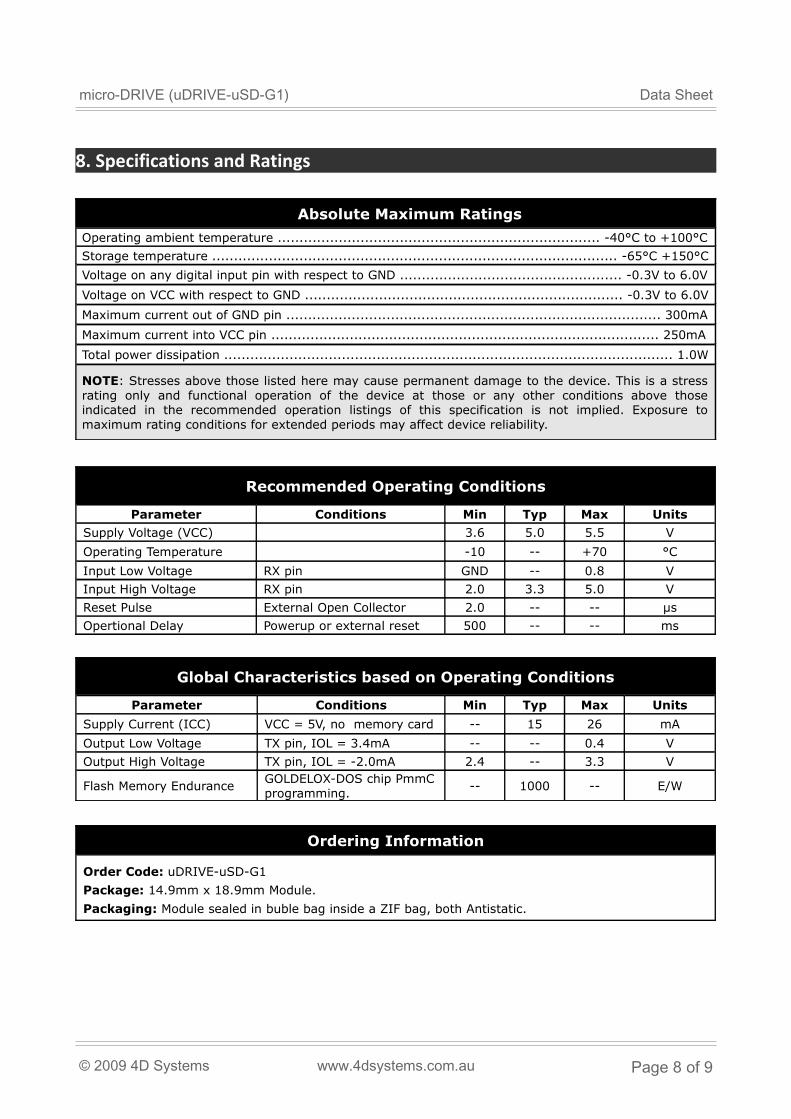
7. Mechanical Details
© 2009 4D Systems www.4dsystems.com.au Page 7 of 9
uUSB-MB5
uUSB-CE5
micro-DRIVE (uDRIVE-uSD-G1) Data Sheet
8. Specifications and Ratings
Absolute Maximum Ratings
Operating ambient temperature .......................................................................... -40°C to +100°C
Storage temperature ............................................................................................. -65°C +150°C
Voltage on any digital input pin with respect to GND ................................................... -0.3V to 6.0V
Voltage on VCC with respect to GND ......................................................................... -0.3V to 6.0V
Maximum current out of GND pin ...................................................................................... 300mA
Maximum current into VCC pin ......................................................................................... 250mA
Total power dissipation ....................................................................................................... 1.0W
NOTE: Stresses above those listed here may cause permanent damage to the device. This is a stress rating only and functional operation of the device at those or any other conditions above those indicated in the recommended operation listings of this specification is not implied. Exposure to maximum rating conditions for extended periods may affect device reliability.
Recommended Operating Conditions
Parameter Conditions Min Typ Max Units
Supply Voltage (VCC) 3.6 5.0 5.5 V
Operating Temperature -10 -- +70 °C
Input Low Voltage RX pin GND -- 0.8 V
Input High Voltage RX pin 2.0 3.3 5.0 V
Reset Pulse External Open Collector 2.0 -- -- µs
Opertional Delay Powerup or external reset 500 -- -- ms
Global Characteristics based on Operating Conditions
Parameter Conditions Min Typ Max Units
Supply Current (ICC) VCC = 5V, no memory card -- 15 26 mA
Output Low Voltage TX pin, IOL = 3.4mA -- -- 0.4 V
Output High Voltage TX pin, IOL = -2.0mA 2.4 -- 3.3 V
Flash Memory EnduranceGOLDELOX-DOS chip PmmC programming.
-- 1000 -- E/W
Ordering Information
Order Code: uDRIVE-uSD-G1
Package: 14.9mm x 18.9mm Module.
Packaging: Module sealed in buble bag inside a ZIF bag, both Antistatic.
© 2009 4D Systems www.4dsystems.com.au Page 8 of 9
micro-DRIVE (uDRIVE-uSD-G1) Data Sheet
Proprietory Information
The information contained in this document is the property of 4D Systems Pty. Ltd. and may be the subject of patents pending or granted, and must not be copied or disclosed with out prior written permission.
4D Systems endeavours to ensure that the information in this document is correct and fairly stated but does not accept liability for any error or omission. The development of 4D Systems products and services is continuous and published information may not be up to date. It is important to check the current position with 4D Systems.
All trademarks belong to their respective owners and are recognised and acknowledged.
Disclaimer of Warranties & Limitation of Liability
4D Systems makes no warranty, either express or implied with respect to any product, and specifically disclaims all other warranties, including, without limitation, warranties for merchantability, non-infringement and fitness for any particular purpose.
Information contained in this publication regarding device applications and the like is provided only for your convenience and may be superseded by updates. It is your responsibility to ensure that your application meets with your specifications.
In no event shall 4D Systems be liable to the buyer or to any third party for any indirect, incidental, special, consequential, punitive or exemplary damages (including without limitation lost profits, lost savings, or loss of business opportunity) arising out of or relating to any product or service provided or to be provided by 4D Systems, or the use or inability to use the same, even if 4D Systems has been advised of the possibility of such damages.
Use of 4D Systems’ devices in life support and/or safety applications is entirely at the buyer’s risk, and the buyer agrees to defend, indemnify and hold harmless 4D Systems from any and all damages, claims, suits, or expenses resulting from such use. No licenses are conveyed, implicitly or otherwise, under any 4D Systems intellectual property rights.
Copyright 4D Systems Pty. Ltd. 2000-2009.
© 2009 4D Systems www.4dsystems.com.au Page 9 of 9