49491102 how to draw drawing and detailing with solidworks
DESCRIPTION
How to Draw Drawing and Detailing With SolidworksTRANSCRIPT

Drawing and Detailing with SolidWorks A Workbook for SolidWorks 2001/2001Plus
by David C. Planchard and Marie P. Planchard
A Competency Based Approach Referencing the ASME Y14 Engineering
Drawing and Related Documentation Practices
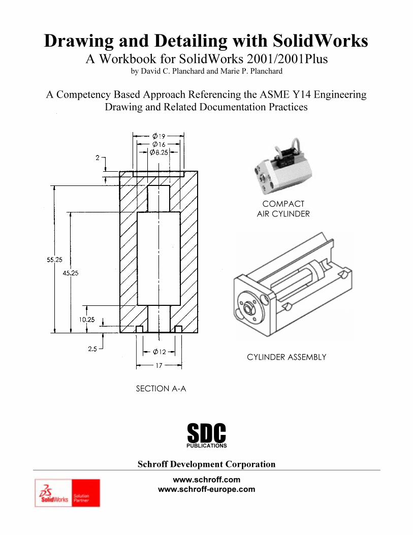
CYLINDER ASSEMBLY
COMPACT
AIR CYLINDER
SECTION A-A
PUBLICATIONS
Schroff Development Corporation
www.schroff.com
www.schroff-europe.com
SDC
Drawing and Detailing with SolidWorks 2001/2001Plus Drawing Template and Sheet Format
PAGE 1-1
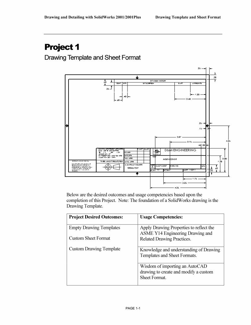
Project 1
Drawing Template and Sheet Format
Below are the desired outcomes and usage competencies based upon the completion of this Project. Note: The foundation of a SolidWorks drawing is the Drawing Template.
Project Desired Outcomes: Usage Competencies:
Apply Drawing Properties to reflect the ASME Y14 Engineering Drawing and Related Drawing Practices.
Knowledge and understanding of Drawing Templates and Sheet Formats.
Empty Drawing Templates
Custom Sheet Format
Custom Drawing Template
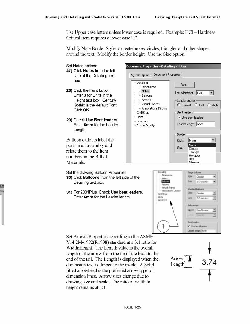
Wisdom of importing an AutoCAD drawing to create and modify a custom Sheet Format.

Drawing Template and Sheet Format Drawing and Detailing with SolidWorks 2001/2001Plus
PAGE 1-2
Notes
Drawing and Detailing with SolidWorks 2001/2001Plus Drawing Template and Sheet Format
PAGE 1-3
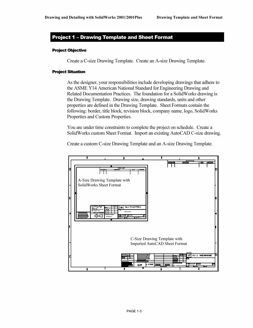
Project 1 – Drawing Template and Sheet Format
Project Objective
Create a C-size Drawing Template. Create an A-size Drawing Template.
Project Situation
As the designer, your responsibilities include developing drawings that adhere to the ASME Y14 American National Standard for Engineering Drawing and Related Documentation Practices. The foundation for a SolidWorks drawing is the Drawing Template. Drawing size, drawing standards, units and other properties are defined in the Drawing Template. Sheet Formats contain the following: border, title block, revision block, company name, logo, SolidWorks Properties and Custom Properties.
You are under time constraints to complete the project on schedule. Create a SolidWorks custom Sheet Format. Import an existing AutoCAD C-size drawing.
Create a custom C-size Drawing Template and an A-size Drawing Template.
C-Size Drawing Template with
Imported AutoCAD Sheet Format
A-Size Drawing Template with
SolidWorks Sheet Format
Drawing Template and Sheet Format Drawing and Detailing with SolidWorks 2001/2001Plus
PAGE 1-4
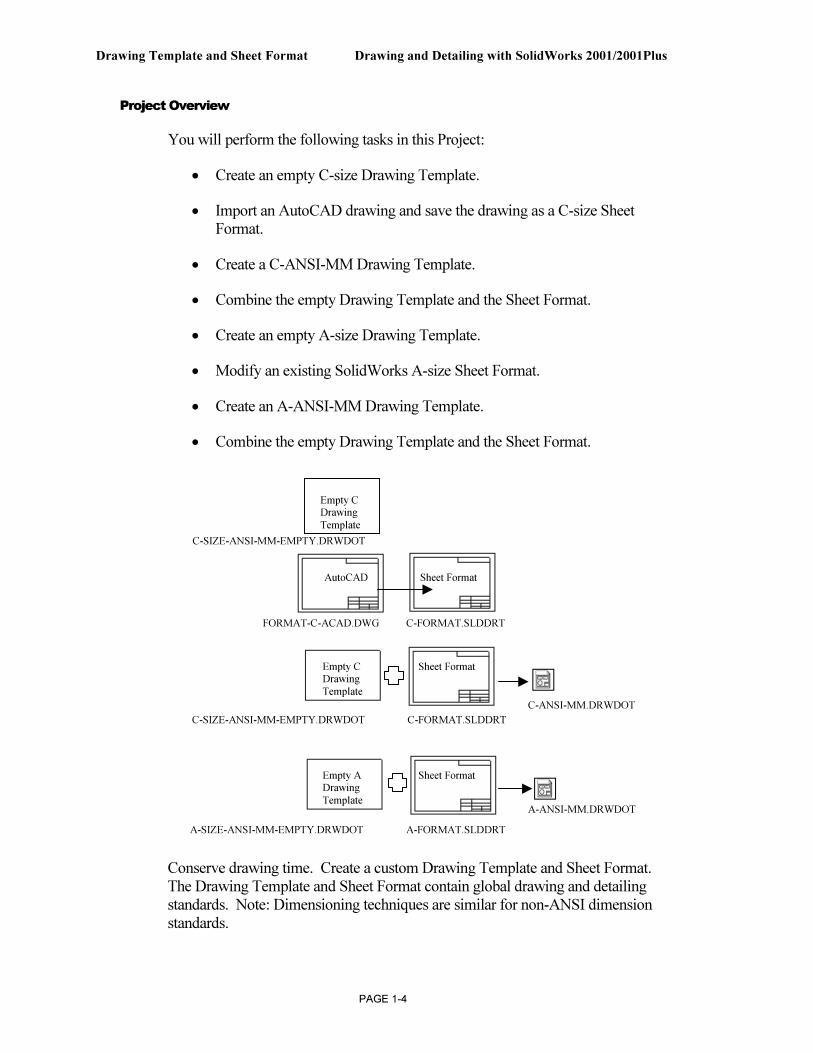
Project Overview
You will perform the following tasks in this Project:
• Create an empty C-size Drawing Template.
• Import an AutoCAD drawing and save the drawing as a C-size Sheet Format.
• Create a C-ANSI-MM Drawing Template.
• Combine the empty Drawing Template and the Sheet Format.
• Create an empty A-size Drawing Template.
• Modify an existing SolidWorks A-size Sheet Format.
• Create an A-ANSI-MM Drawing Template.
• Combine the empty Drawing Template and the Sheet Format.
Conserve drawing time. Create a custom Drawing Template and Sheet Format. The Drawing Template and Sheet Format contain global drawing and detailing standards. Note: Dimensioning techniques are similar for non-ANSI dimension standards.
FORMAT-C-ACAD.DWG C-FORMAT.SLDDRT
C-SIZE-ANSI-MM-EMPTY.DRWDOT C-FORMAT.SLDDRT
A-SIZE-ANSI-MM-EMPTY.DRWDOT A-FORMAT.SLDDRT
C-ANSI-MM.DRWDOT
A-ANSI-MM.DRWDOT
AutoCAD Sheet Format
Empty C Sheet Format
Drawing
Template
Empty A Sheet Format
Drawing
Template
Empty C
Drawing
Template C-SIZE-ANSI-MM-EMPTY.DRWDOT
Drawing and Detailing with SolidWorks 2001/2001Plus Drawing Template and Sheet Format
PAGE 1-5
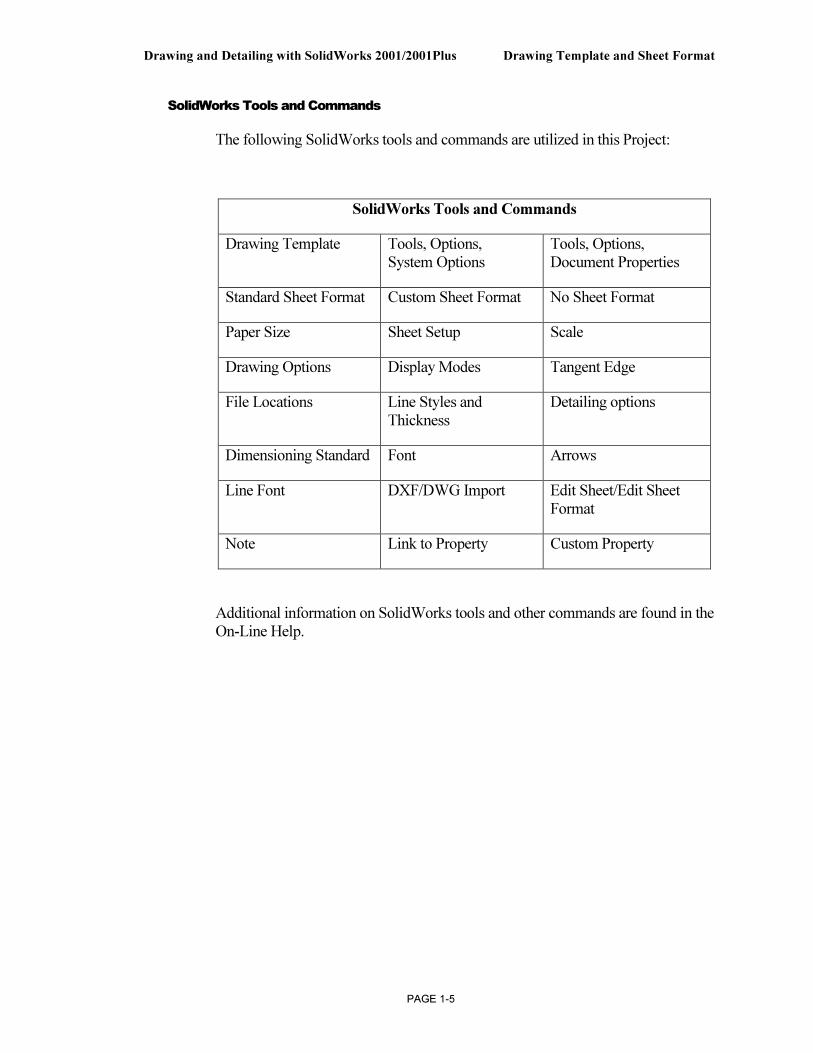
SolidWorks Tools and Commands
The following SolidWorks tools and commands are utilized in this Project:
SolidWorks Tools and Commands
Drawing Template Tools, Options, System Options
Tools, Options, Document Properties
Standard Sheet Format Custom Sheet Format No Sheet Format
Paper Size Sheet Setup Scale
Drawing Options Display Modes Tangent Edge
File Locations Line Styles and Thickness
Detailing options
Dimensioning Standard Font Arrows
Line Font DXF/DWG Import Edit Sheet/Edit Sheet Format
Note Link to Property Custom Property
Additional information on SolidWorks tools and other commands are found in the On-Line Help.
Drawing Template and Sheet Format Drawing and Detailing with SolidWorks 2001/2001Plus
PAGE 1-6
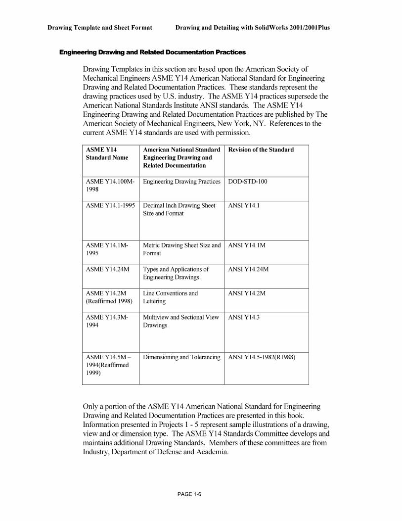
Engineering Drawing and Related Documentation Practices
Drawing Templates in this section are based upon the American Society of Mechanical Engineers ASME Y14 American National Standard for Engineering Drawing and Related Documentation Practices. These standards represent the drawing practices used by U.S. industry. The ASME Y14 practices supersede the American National Standards Institute ANSI standards. The ASME Y14 Engineering Drawing and Related Documentation Practices are published by The American Society of Mechanical Engineers, New York, NY. References to the current ASME Y14 standards are used with permission.
ASME Y14
Standard Name
American National Standard
Engineering Drawing and
Related Documentation
Revision of the Standard
ASME Y14.100M-
1998
Engineering Drawing Practices DOD-STD-100
ASME Y14.1-1995 Decimal Inch Drawing Sheet
Size and Format
ANSI Y14.1
ASME Y14.1M-
1995
Metric Drawing Sheet Size and
Format
ANSI Y14.1M
ASME Y14.24M Types and Applications of
Engineering Drawings
ANSI Y14.24M
ASME Y14.2M
(Reaffirmed 1998)
Line Conventions and
Lettering
ANSI Y14.2M
ASME Y14.3M-
1994
Multiview and Sectional View
Drawings
ANSI Y14.3
ASME Y14.5M –
1994(Reaffirmed
1999)
Dimensioning and Tolerancing ANSI Y14.5-1982(R1988)
Only a portion of the ASME Y14 American National Standard for Engineering Drawing and Related Documentation Practices are presented in this book. Information presented in Projects 1 - 5 represent sample illustrations of a drawing, view and or dimension type. The ASME Y14 Standards Committee develops and maintains additional Drawing Standards. Members of these committees are from Industry, Department of Defense and Academia.
Drawing and Detailing with SolidWorks 2001/2001Plus Drawing Template and Sheet Format
PAGE 1-7
Companies create their own drawing standards based upon one or more of the following:
• ASME Y14
• ISO or other International drawing standards
• Older ANSI standards
• Military standards
Of course there is also the “We’ve always done it this way” drawing standard or “Go ask the Drafting Supervisor” drawing standard.
Drawing Template and Sheet Format Drawing and Detailing with SolidWorks 2001/2001Plus
PAGE 1-8
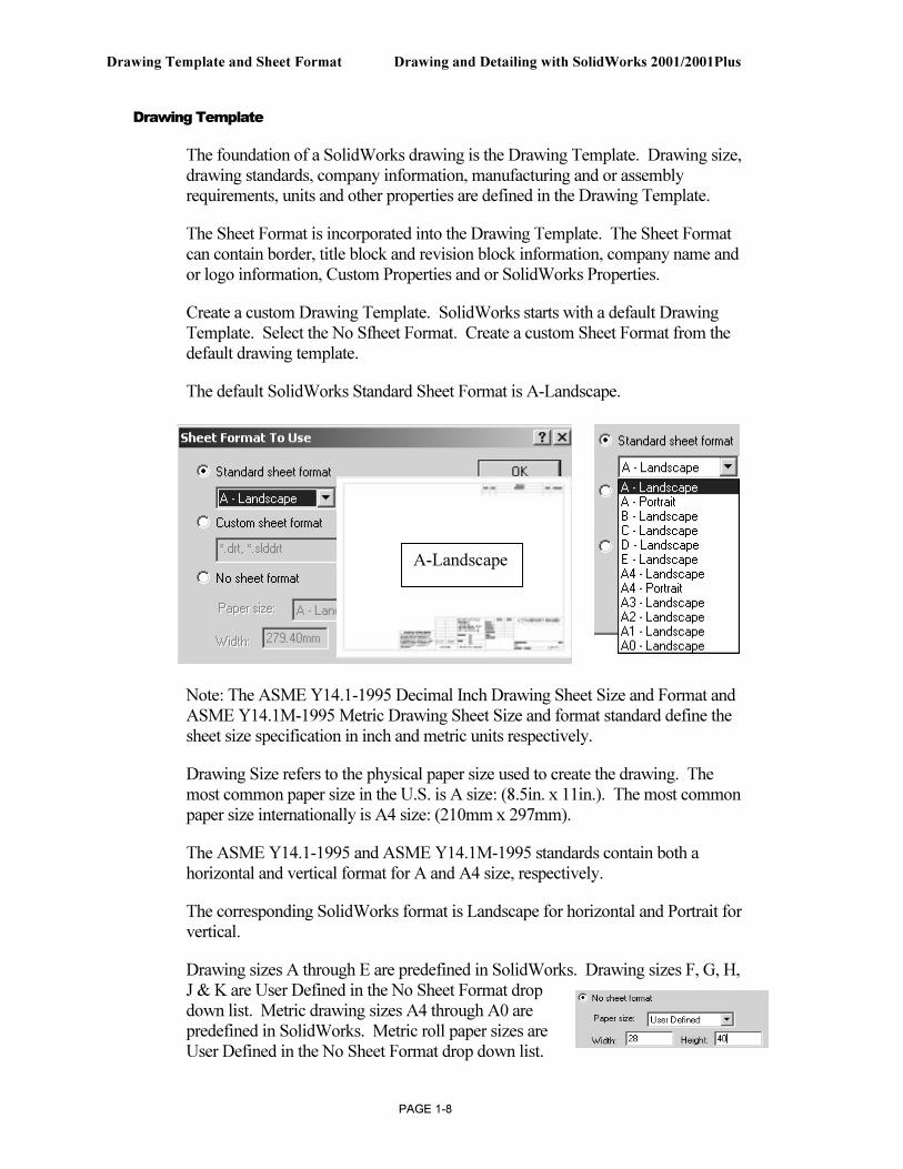
Drawing Template
The foundation of a SolidWorks drawing is the Drawing Template. Drawing size, drawing standards, company information, manufacturing and or assembly requirements, units and other properties are defined in the Drawing Template.
The Sheet Format is incorporated into the Drawing Template. The Sheet Format can contain border, title block and revision block information, company name and or logo information, Custom Properties and or SolidWorks Properties.
Create a custom Drawing Template. SolidWorks starts with a default Drawing Template. Select the No Sfheet Format. Create a custom Sheet Format from the default drawing template.
The default SolidWorks Standard Sheet Format is A-Landscape.
Note: The ASME Y14.1-1995 Decimal Inch Drawing Sheet Size and Format and ASME Y14.1M-1995 Metric Drawing Sheet Size and format standard define the sheet size specification in inch and metric units respectively.
Drawing Size refers to the physical paper size used to create the drawing. The most common paper size in the U.S. is A size: (8.5in. x 11in.). The most common paper size internationally is A4 size: (210mm x 297mm).
The ASME Y14.1-1995 and ASME Y14.1M-1995 standards contain both a horizontal and vertical format for A and A4 size, respectively.
The corresponding SolidWorks format is Landscape for horizontal and Portrait for vertical.
Drawing sizes A through E are predefined in SolidWorks. Drawing sizes F, G, H, J & K are User Defined in the No Sheet Format drop down list. Metric drawing sizes A4 through A0 are predefined in SolidWorks. Metric roll paper sizes are User Defined in the No Sheet Format drop down list.
A-Landscape
Drawing and Detailing with SolidWorks 2001/2001Plus Drawing Template and Sheet Format
PAGE 1-9
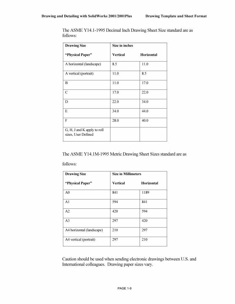
The ASME Y14.1-1995 Decimal Inch Drawing Sheet Size standard are as follows:
Drawing Size
“Physical Paper”
Size in inches
Vertical Horizontal
A horizontal (landscape) 8.5 11.0
A vertical (portrait) 11.0 8.5
B 11.0 17.0
C 17.0 22.0
D 22.0 34.0
E 34.0 44.0
F 28.0 40.0
G, H, J and K apply to roll
sizes, User Defined
The ASME Y14.1M-1995 Metric Drawing Sheet Sizes standard are as
follows:
Drawing Size
“Physical Paper”
Size in Millimeters
Vertical Horizontal
A0 841 1189
A1 594 841
A2 420 594
A3 297 420
A4 horizontal (landscape) 210 297
A4 vertical (portrait) 297 210
Caution should be used when sending electronic drawings between U.S. and International colleagues. Drawing paper sizes vary.
Drawing Template and Sheet Format Drawing and Detailing with SolidWorks 2001/2001Plus
PAGE 1-10
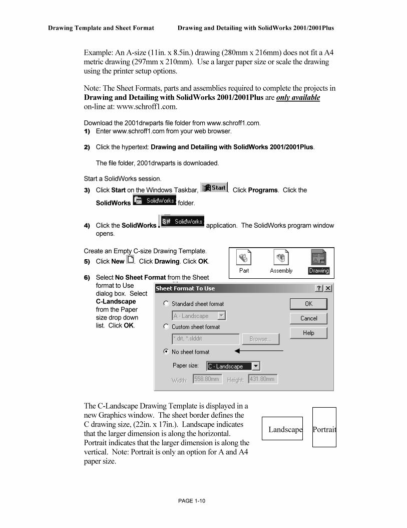
Example: An A-size (11in. x 8.5in.) drawing (280mm x 216mm) does not fit a A4 metric drawing (297mm x 210mm). Use a larger paper size or scale the drawing using the printer setup options.
Note: The Sheet Formats, parts and assemblies required to complete the projects in Drawing and Detailing with SolidWorks 2001/2001Plus are only available on-line at: www.schroff1.com.
Download the 2001drwparts file folder from www.schroff1.com. 1) Enter www.schroff1.com from your web browser.
2) Click the hypertext: Drawing and Detailing with SolidWorks 2001/2001Plus.
The file folder, 2001drwparts is downloaded.
Start a SolidWorks session.
3) Click Start on the Windows Taskbar, . Click Programs. Click the
SolidWorks folder.
4) Click the SolidWorks application. The SolidWorks program window opens.
Create an Empty C-size Drawing Template.
5) Click New . Click Drawing. Click OK.
6) Select No Sheet Format from the Sheet format to Use dialog box. Select C-Landscape from the Paper size drop down list. Click OK.
The C-Landscape Drawing Template is displayed in a new Graphics window. The sheet border defines the C drawing size, (22in. x 17in.). Landscape indicates that the larger dimension is along the horizontal. Portrait indicates that the larger dimension is along the vertical. Note: Portrait is only an option for A and A4 paper size.
Landscape Portrait
Drawing and Detailing with SolidWorks 2001/2001Plus Drawing Template and Sheet Format
PAGE 1-11
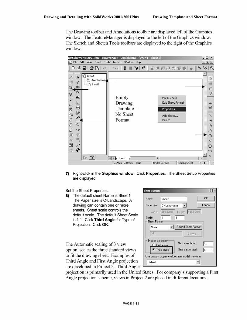
The Drawing toolbar and Annotations toolbar are displayed left of the Graphics window. The FeatureManager is displayed to the left of the Graphics window. The Sketch and Sketch Tools toolbars are displayed to the right of the Graphics window.
7) Right-click in the Graphics window. Click Properties. The Sheet Setup Properties are displayed.
Set the Sheet Properties. 8) The default sheet Name is Sheet1.
The Paper size is C-Landscape. A drawing can contain one or more sheets. Sheet scale controls the default scale. The default Sheet Scale is 1:1. Click Third Angle for Type of Projection. Click OK.
The Automatic scaling of 3 view option, scales the three standard views to fit the drawing sheet. Examples of Third Angle and First Angle projection are developed in Project 2. Third Angle projection is primarily used in the United States. For company’s supporting a First Angle projection scheme, views in Project 2 are placed in different locations.
Empty Drawing Template – No Sheet
Format
Drawing Template and Sheet Format Drawing and Detailing with SolidWorks 2001/2001Plus
PAGE 1-12
System Options and Document Properties
System Options are stored in the registry of the computer. System Options is not part of the document. Changes to the System Options affect all current and future documents.
ANSI or ISO Dimension Standard, Units and other Properties are set in Document Properties. Document Properties apply only to the current document. When you save the current document as a template, the current parameters are stored with the template. New documents that utilize the same template contain these set parameters.
Conserve drawing time. Set the System Options and Document Properties before you begin a drawing.
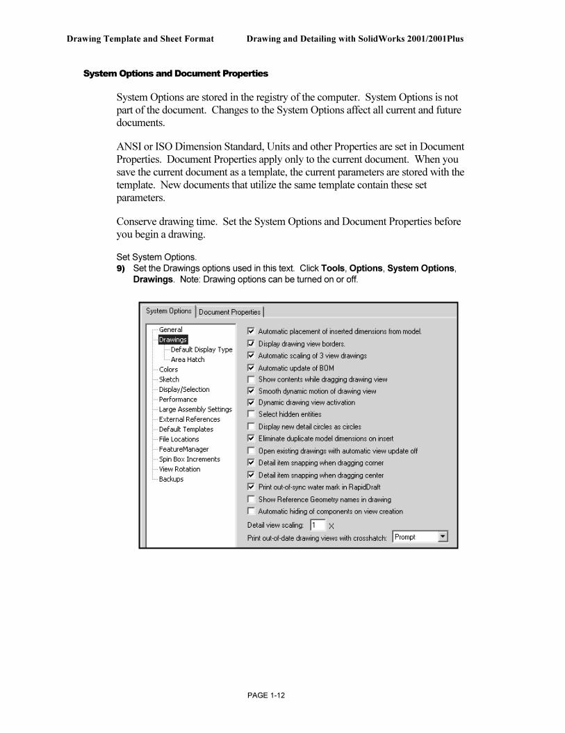
Set System Options. 9) Set the Drawings options used in this text. Click Tools, Options, System Options,
Drawings. Note: Drawing options can be turned on or off.
Drawing and Detailing with SolidWorks 2001/2001Plus Drawing Template and Sheet Format
PAGE 1-13
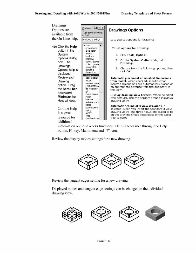
Drawings Options are available from the On-Line help.
10) Click the Help button in the System Options dialog box. The Drawings Options help is displayed. Review each Drawing option. Drag the Scroll bar downward. Minimize the Help window.
On-line Help is a great resource for additional information on SolidWorks functions. Help is accessible through the Help button, F1 key, Main menu and “?” icon.
Review the display modes settings for a new drawing.
Review the tangent edges setting for a new drawing.
Displayed modes and tangent edge settings can be changed in the individual drawing view.
Drawing Template and Sheet Format Drawing and Detailing with SolidWorks 2001/2001Plus
PAGE 1-14
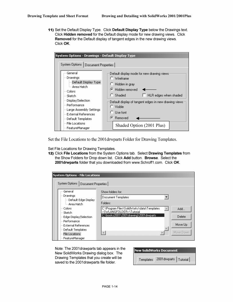
11) Set the Default Display Type. Click Default Display Type below the Drawings text. Click Hidden removed for the Default display mode for new drawing views. Click Removed for the Default display of tangent edges in the new drawing views. Click OK.
Set the File Locations to the 2001drwparts Folder for Drawing Templates.
Set File Locations for Drawing Templates. 12) Click File Locations from the System Options tab. Select Drawing Templates from
the Show Folders for Drop down list. Click Add button. Browse. Select the 2001drwparts folder that you downloaded from www.Schroff1.com. Click OK.
Note: The 2001drawparts tab appears in the New SolidWorks Drawing dialog box. The Drawing Templates that you create will be saved to the 2001drawparts file folder.
Shaded Option (2001 Plus)
Drawing and Detailing with SolidWorks 2001/2001Plus Drawing Template and Sheet Format
PAGE 1-15
The Drawing Properties Detailing options provide the ability to address: dimensioning standards, text style, center marks, witness lines, arrow styles, tolerance and precision. Drawing Properties are stored with the Drawing Template.
There are numerous text styles and sizes available in SolidWorks. Companies develop drawing format standards and use specific text height for Metric and English drawings. The ASME Y14.2M-1992(R1998) standard lists the lettering, arrowhead and line conventions and lettering conventions for engineering drawings and related documentation practices. Examples:
• Font: Utilize a single stroke, gothic lettering in all upper case letters. Use a single font. Century Gothic is the default SolidWorks font. Create a test page to insure that both Windows and your particular Printer/Plotter drivers support the selected font.
• Minimum letter height will vary depending upon usage on a drawing:
o Minimum letter height used for drawing title, drawing size, CAGE Code, drawing number and revision letter positioned inside the Title block is .12in. (3mm) for A, B and C inch sizes and A2, A3 and A4 metric drawing sizes: Text height is .24in. (6mm) for D and E inch drawing sizes and A0, A1 metric drawing sizes.
o Minimum letter height for Section views, Zone letters and numerals is .24in. (6mm) for all drawing sizes. Set Text size for Section, Detail and View font to 6mm.
o Minimum letter height for drawing block headings is .10in. (2.5mm) for all drawing sizes.
o Minimum letter height for all other characters is .12in. (3mm) for all drawing sizes. Set Text size for Dimension and Note Font to 3mm.
• Arrowheads: Utilize solid filled single style arrowhead, with a 3:1 ratio of arrow length to arrow width. The arrowhead width is proportionate to the line thickness. The Dimension line thickness is 0.3mm. In this project, the arrow length is 3mm. Arrow width is 1mm. SolidWorks defines arrow size with three options: Height, Width and Length. Height corresponds to arrow width. Width corresponds to arrow length. Length corresponds to the distance from the tip of the arrow to the end of the tail.
• The Section line thickness is 0.6mm. The arrow length is 6mm. The arrow width is 2mm.
• Line Widths: The ASME Y14.2M-1992(R1998) standard recommends two line widths with a 2:1 ratio. The minimum width of a thin line is 0.3mm. The minimum width of a thick, “normal” line is 0.6mm. Note: A single width
Drawing Template and Sheet Format Drawing and Detailing with SolidWorks 2001/2001Plus
PAGE 1-16
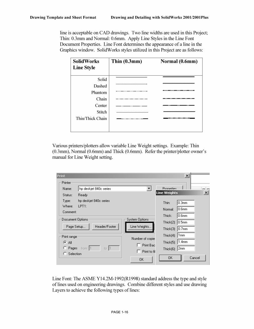
line is acceptable on CAD drawings. Two line widths are used in this Project; Thin: 0.3mm and Normal: 0.6mm. Apply Line Styles in the Line Font Document Properties. Line Font determines the appearance of a line in the Graphics window. SolidWorks styles utilized in this Project are as follows:
SolidWorks
Line Style
Thin (0.3mm) Normal (0.6mm)
Solid
Dashed
Phantom
Chain
Center
Stitch
Thin/Thick Chain
Various printers/plotters allow variable Line Weight settings. Example: Thin (0.3mm), Normal (0.6mm) and Thick (0.6mm). Refer the printer/plotter owner’s manual for Line Weight setting.
Line Font: The ASME Y14.2M-1992(R1998) standard address the type and style of lines used on engineering drawings. Combine different styles and use drawing Layers to achieve the following types of lines:
Drawing and Detailing with SolidWorks 2001/2001Plus Drawing Template and Sheet Format
PAGE 1-17
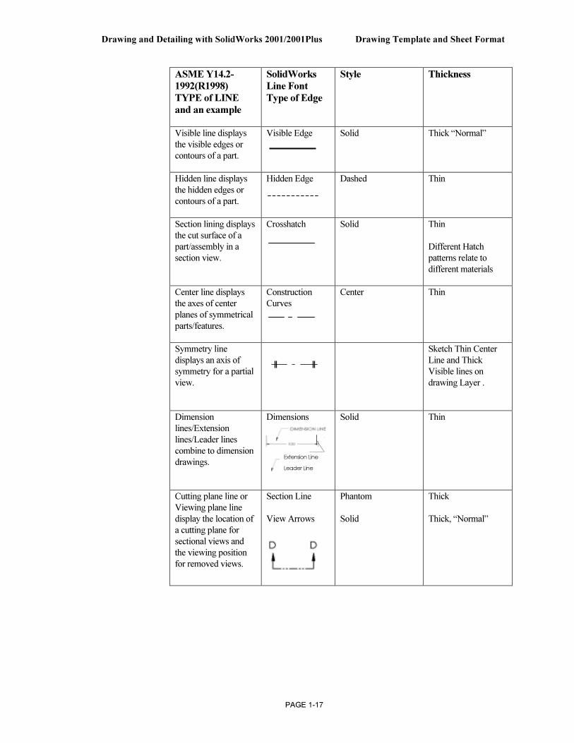
ASME Y14.2-
1992(R1998)
TYPE of LINE
and an example
SolidWorks
Line Font
Type of Edge
Style Thickness
Visible line displays
the visible edges or
contours of a part.
Visible Edge Solid Thick “Normal”
Hidden line displays
the hidden edges or
contours of a part.
Hidden Edge Dashed Thin
Section lining displays
the cut surface of a
part/assembly in a
section view.
Crosshatch Solid Thin
Different Hatch
patterns relate to
different materials
Center line displays
the axes of center
planes of symmetrical
parts/features.
Construction
Curves
Center Thin
Symmetry line
displays an axis of
symmetry for a partial
view.
Sketch Thin Center
Line and Thick
Visible lines on
drawing Layer .
Dimension
lines/Extension
lines/Leader lines
combine to dimension
drawings.
Dimensions
Solid
Thin
Cutting plane line or
Viewing plane line
display the location of
a cutting plane for
sectional views and
the viewing position
for removed views.
Section Line
View Arrows
Phantom
Solid
Thick
Thick, “Normal”
Extension Line
Leader Line
Drawing Template and Sheet Format Drawing and Detailing with SolidWorks 2001/2001Plus
PAGE 1-18
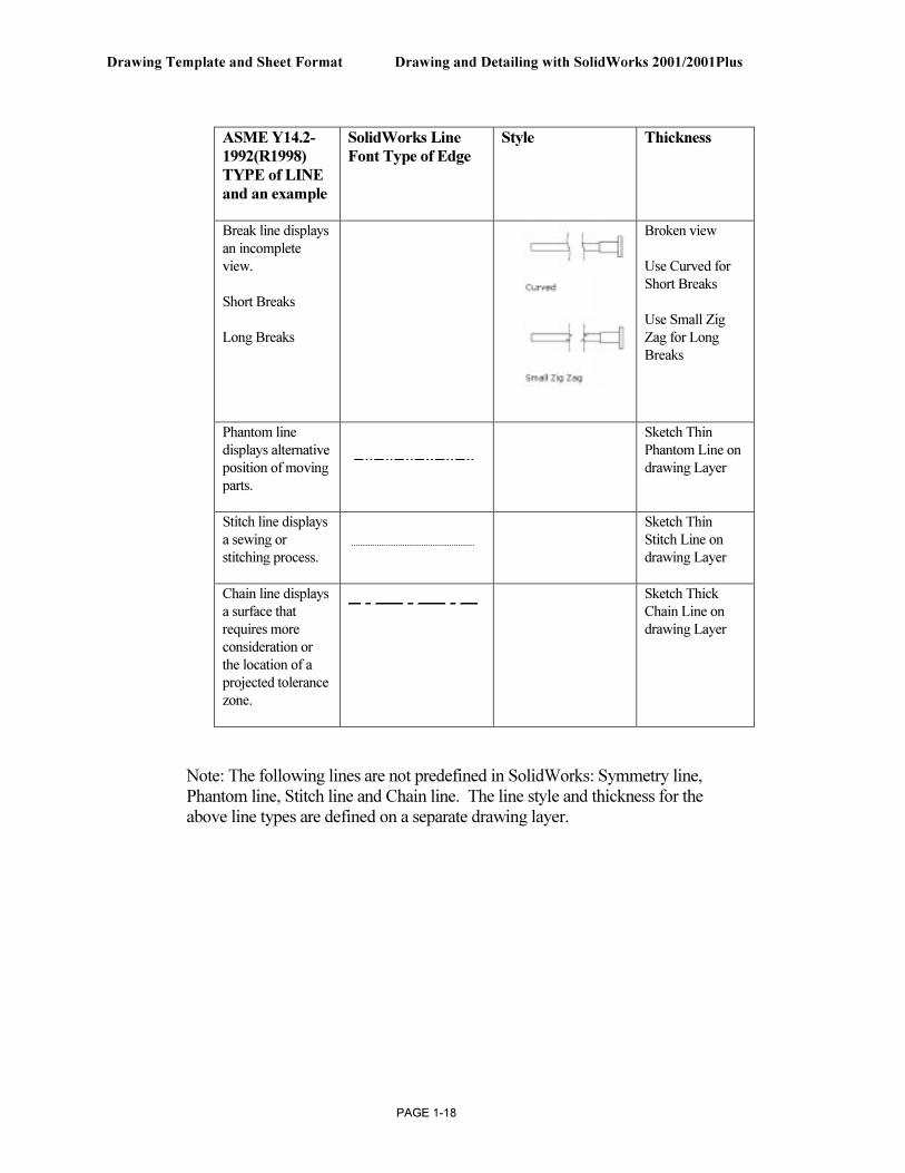
ASME Y14.2-
1992(R1998)
TYPE of LINE
and an example
SolidWorks Line
Font Type of Edge
Style Thickness
Break line displays
an incomplete
view.
Short Breaks
Long Breaks
Broken view
Use Curved for
Short Breaks
Use Small Zig
Zag for Long
Breaks
Phantom line
displays alternative
position of moving
parts.
Sketch Thin
Phantom Line on
drawing Layer
Stitch line displays
a sewing or
stitching process.
Sketch Thin
Stitch Line on
drawing Layer
Chain line displays
a surface that
requires more
consideration or
the location of a
projected tolerance
zone.
Sketch Thick
Chain Line on
drawing Layer
Note: The following lines are not predefined in SolidWorks: Symmetry line, Phantom line, Stitch line and Chain line. The line style and thickness for the above line types are defined on a separate drawing layer.
Drawing and Detailing with SolidWorks 2001/2001Plus Drawing Template and Sheet Format
PAGE 1-19
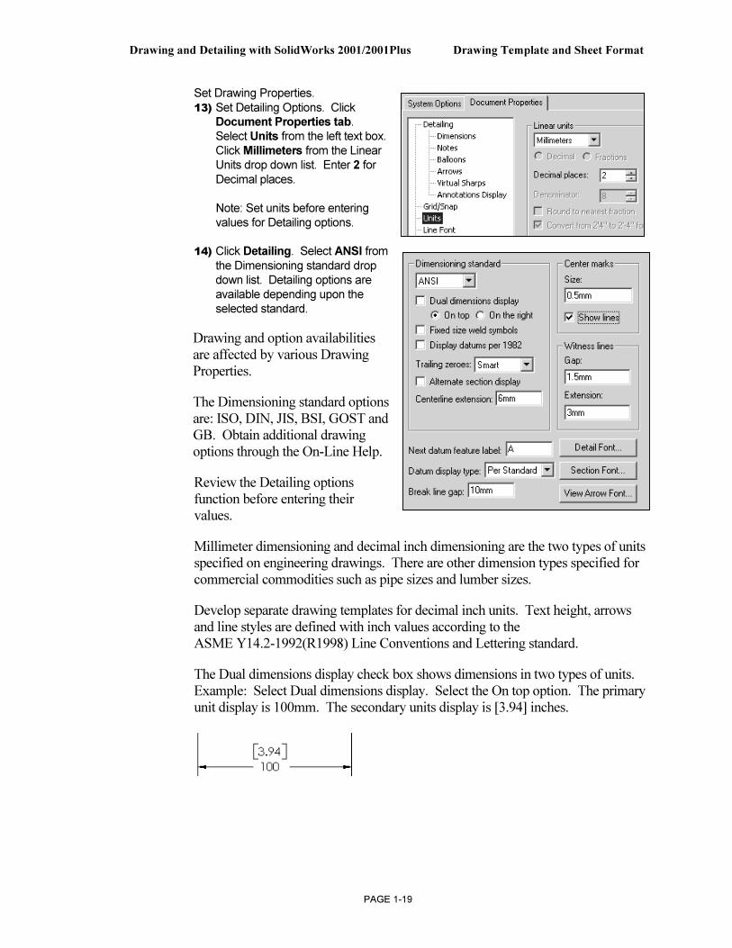
Set Drawing Properties. 13) Set Detailing Options. Click
Document Properties tab. Select Units from the left text box. Click Millimeters from the Linear Units drop down list. Enter 2 for Decimal places.
Note: Set units before entering values for Detailing options.
14) Click Detailing. Select ANSI from the Dimensioning standard drop down list. Detailing options are available depending upon the selected standard.
Drawing and option availabilities are affected by various Drawing Properties.
The Dimensioning standard options are: ISO, DIN, JIS, BSI, GOST and GB. Obtain additional drawing options through the On-Line Help.
Review the Detailing options function before entering their values.
Millimeter dimensioning and decimal inch dimensioning are the two types of units specified on engineering drawings. There are other dimension types specified for commercial commodities such as pipe sizes and lumber sizes.
Develop separate drawing templates for decimal inch units. Text height, arrows and line styles are defined with inch values according to the ASME Y14.2-1992(R1998) Line Conventions and Lettering standard.
The Dual dimensions display check box shows dimensions in two types of units. Example: Select Dual dimensions display. Select the On top option. The primary unit display is 100mm. The secondary units display is [3.94] inches.
Drawing Template and Sheet Format Drawing and Detailing with SolidWorks 2001/2001Plus
PAGE 1-20
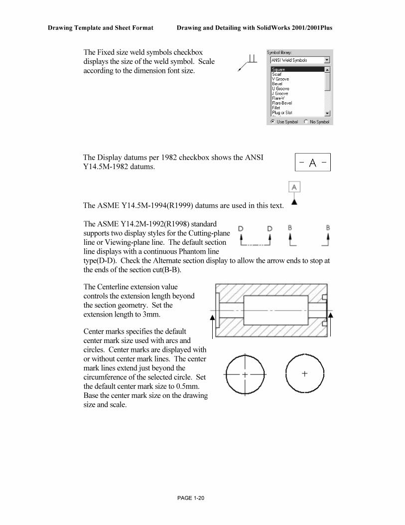
The Fixed size weld symbols checkbox displays the size of the weld symbol. Scale according to the dimension font size.
The Display datums per 1982 checkbox shows the ANSI Y14.5M-1982 datums.
The ASME Y14.5M-1994(R1999) datums are used in this text.
The ASME Y14.2M-1992(R1998) standard supports two display styles for the Cutting-plane line or Viewing-plane line. The default section line displays with a continuous Phantom line type(D-D). Check the Alternate section display to allow the arrow ends to stop at the ends of the section cut(B-B).
The Centerline extension value controls the extension length beyond the section geometry. Set the extension length to 3mm.
Center marks specifies the default center mark size used with arcs and circles. Center marks are displayed with or without center mark lines. The center mark lines extend just beyond the circumference of the selected circle. Set the default center mark size to 0.5mm. Base the center mark size on the drawing size and scale.
Drawing and Detailing with SolidWorks 2001/2001Plus Drawing Template and Sheet Format
PAGE 1-21
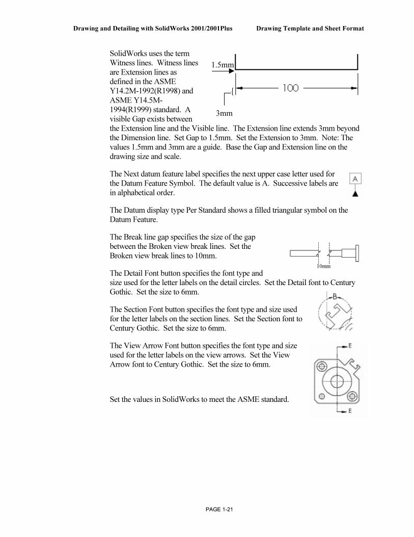
SolidWorks uses the term Witness lines. Witness lines are Extension lines as defined in the ASME Y14.2M-1992(R1998) and ASME Y14.5M-1994(R1999) standard. A visible Gap exists between the Extension line and the Visible line. The Extension line extends 3mm beyond the Dimension line. Set Gap to 1.5mm. Set the Extension to 3mm. Note: The values 1.5mm and 3mm are a guide. Base the Gap and Extension line on the drawing size and scale.
The Next datum feature label specifies the next upper case letter used for the Datum Feature Symbol. The default value is A. Successive labels are in alphabetical order.
The Datum display type Per Standard shows a filled triangular symbol on the Datum Feature.
The Break line gap specifies the size of the gap between the Broken view break lines. Set the Broken view break lines to 10mm.
The Detail Font button specifies the font type and size used for the letter labels on the detail circles. Set the Detail font to Century Gothic. Set the size to 6mm.
The Section Font button specifies the font type and size used for the letter labels on the section lines. Set the Section font to Century Gothic. Set the size to 6mm.
The View Arrow Font button specifies the font type and size used for the letter labels on the view arrows. Set the View Arrow font to Century Gothic. Set the size to 6mm.
Set the values in SolidWorks to meet the ASME standard.
3mm
1.5mm
10mm
Drawing Template and Sheet Format Drawing and Detailing with SolidWorks 2001/2001Plus
PAGE 1-22
Set Detail Options.
15) Enter 3mm for the Centerline extension.
16) Enter 0.5mm for the Center marks.
17) Modify the Witness lines (Extension line) values. Enter 1.5mm for Gap. Enter 3mm for Extension.
18) Enter 10mm for the Break line gap. Note: There is no set value for the Break line gap. Increase the value to accommodate a revolved section.
19) Set the Detail Font. Click the Detail Font button. Enter 6mm for text. Repeat for Section Font and View
Arrow Font. Accept all other defaults from the Detailing text box.
20) Review the Dimension options. Click Dimensions from the left side of the Detailing text box.
2001Plus
Drawing and Detailing with SolidWorks 2001/2001Plus Drawing Template and Sheet Format
PAGE 1-23
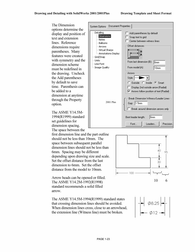
The Dimension options determine the display and position of text and extension lines. Reference dimensions require parentheses. Many features were created with symmetry and the dimension scheme must be redefined in the drawing. Uncheck the Add parentheses by default to save time. Parenthesis can be added to a dimension at anytime through the Property option.
The ASME Y14.5M-1994(R1999) standard set guidelines for dimension spacing. The space between the first dimension line and the part outline should not be less than 10mm. The space between subsequent parallel dimension lines should not be less than 6mm. Spacing may be different depending upon drawing size and scale. Set the offset distance from the last dimension to 6mm. Set the offset distance from the model to 10mm.
Arrow heads can be opened or filled. The ASME Y14.2M-1992(R1998) standard recommends a solid filled arrow.
The ASME Y14.5M-1994(R1999) standard states that crossing dimension lines should be avoided. When dimension lines cross, close to an arrowhead, the extension line (Witness line) must be broken.
10 6
2001 Plus
Drawing Template and Sheet Format Drawing and Detailing with SolidWorks 2001/2001Plus
PAGE 1-24
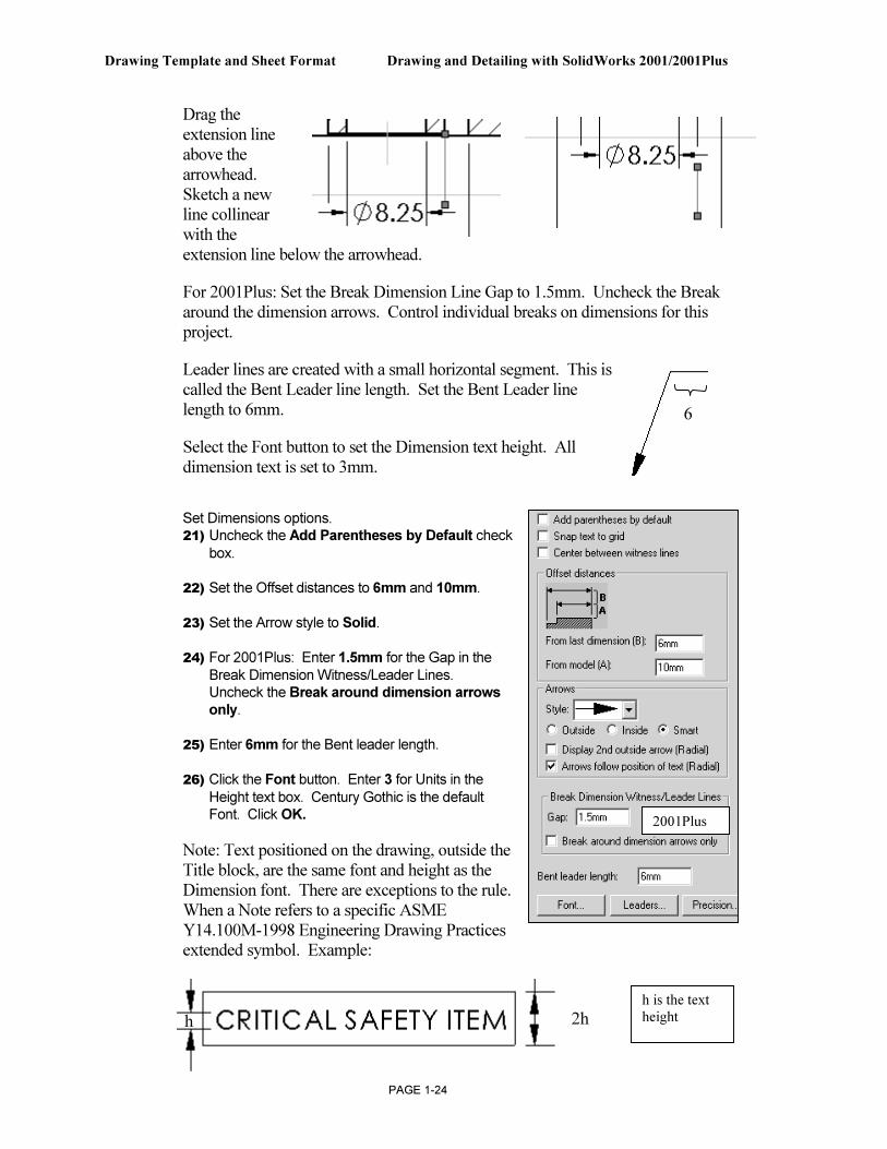
Drag the extension line above the arrowhead. Sketch a new line collinear with the extension line below the arrowhead.
For 2001Plus: Set the Break Dimension Line Gap to 1.5mm. Uncheck the Break around the dimension arrows. Control individual breaks on dimensions for this project.
Leader lines are created with a small horizontal segment. This is called the Bent Leader line length. Set the Bent Leader line length to 6mm.
Select the Font button to set the Dimension text height. All dimension text is set to 3mm.
Set Dimensions options. 21) Uncheck the Add Parentheses by Default check
box.
22) Set the Offset distances to 6mm and 10mm.
23) Set the Arrow style to Solid.
24) For 2001Plus: Enter 1.5mm for the Gap in the Break Dimension Witness/Leader Lines. Uncheck the Break around dimension arrows
only.
25) Enter 6mm for the Bent leader length.
26) Click the Font button. Enter 3 for Units in the
Height text box. Century Gothic is the default Font. Click OK.
Note: Text positioned on the drawing, outside the Title block, are the same font and height as the Dimension font. There are exceptions to the rule. When a Note refers to a specific ASME Y14.100M-1998 Engineering Drawing Practices extended symbol. Example:
6
2h h
h is the text
height
2001Plus
Drawing and Detailing with SolidWorks 2001/2001Plus Drawing Template and Sheet Format
PAGE 1-25
Use Upper case letters unless lower case is required. Example: HCl – Hardness Critical Item requires a lower case “l”.
Modify Note Border Style to create boxes, circles, triangles and other shapes around the text. Modify the border height. Use the Size option.
Set Notes options. 27) Click Notes from the left
side of the Detailing text box.
28) Click the Font button. Enter 3 for Units in the Height text box. Century Gothic is the default Font. Click OK.
29) Check Use Bent leaders. Enter 6mm for the Leader Length.
Balloon callouts label the parts in an assembly and relate them to the item numbers in the Bill of Materials.
Set the drawing Balloon Properties. 30) Click Balloons from the left side of the
Detailing text box.
31) For 2001Plus: Check Use bent leaders. Enter 6mm for the Leader length.
Set Arrows Properties according to the ASME Y14.2M-1992(R1998) standard at a 3:1 ratio for Width:Height. The Length value is the overall length of the arrow from the tip of the head to the end of the tail. The Length is displayed when the dimension text is flipped to the inside. A Solid filled arrowhead is the preferred arrow type for dimension lines. Arrow sizes change due to drawing size and scale. The ratio of width to height remains at 3:1.
Arrow
Length
Drawing Template and Sheet Format Drawing and Detailing with SolidWorks 2001/2001Plus
PAGE 1-26
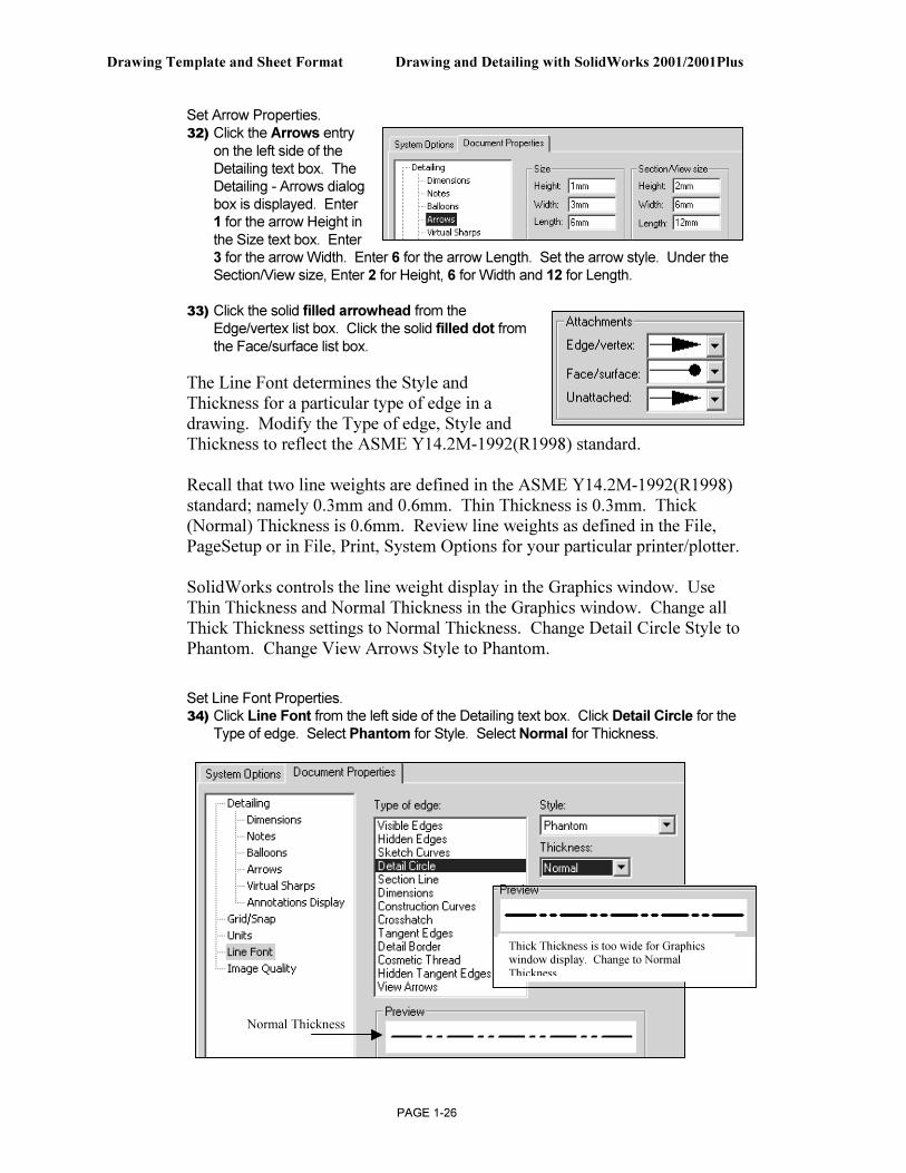
Set Arrow Properties. 32) Click the Arrows entry
on the left side of the Detailing text box. The Detailing - Arrows dialog box is displayed. Enter 1 for the arrow Height in the Size text box. Enter 3 for the arrow Width. Enter 6 for the arrow Length. Set the arrow style. Under the Section/View size, Enter 2 for Height, 6 for Width and 12 for Length.
33) Click the solid filled arrowhead from the Edge/vertex list box. Click the solid filled dot from the Face/surface list box.
The Line Font determines the Style and Thickness for a particular type of edge in a drawing. Modify the Type of edge, Style and Thickness to reflect the ASME Y14.2M-1992(R1998) standard. Recall that two line weights are defined in the ASME Y14.2M-1992(R1998) standard; namely 0.3mm and 0.6mm. Thin Thickness is 0.3mm. Thick (Normal) Thickness is 0.6mm. Review line weights as defined in the File, PageSetup or in File, Print, System Options for your particular printer/plotter. SolidWorks controls the line weight display in the Graphics window. Use Thin Thickness and Normal Thickness in the Graphics window. Change all Thick Thickness settings to Normal Thickness. Change Detail Circle Style to Phantom. Change View Arrows Style to Phantom.
Set Line Font Properties. 34) Click Line Font from the left side of the Detailing text box. Click Detail Circle for the
Type of edge. Select Phantom for Style. Select Normal for Thickness.
Thick Thickness is too wide for Graphics window display. Change to Normal
Thickness
Normal Thickness
Drawing and Detailing with SolidWorks 2001/2001Plus Drawing Template and Sheet Format
PAGE 1-27
35) Click Section line for the Type of edge. Click Normal for Thickness.
36) Click View Arrows for the Type of edge. Click Solid for Style. Click Normal for Thickness.
37) Exit Drawing Properties. Click OK.
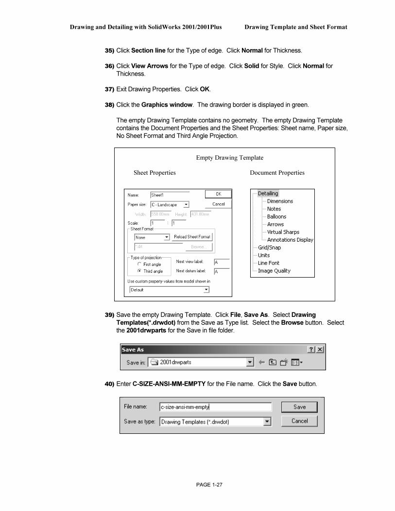
38) Click the Graphics window. The drawing border is displayed in green.
The empty Drawing Template contains no geometry. The empty Drawing Template contains the Document Properties and the Sheet Properties: Sheet name, Paper size, No Sheet Format and Third Angle Projection.
39) Save the empty Drawing Template. Click File, Save As. Select Drawing
Templates(*.drwdot) from the Save as Type list. Select the Browse button. Select the 2001drwparts for the Save in file folder.
40) Enter C-SIZE-ANSI-MM-EMPTY for the File name. Click the Save button.
Empty Drawing Template
Sheet Properties Document Properties
Drawing Template and Sheet Format Drawing and Detailing with SolidWorks 2001/2001Plus
PAGE 1-28
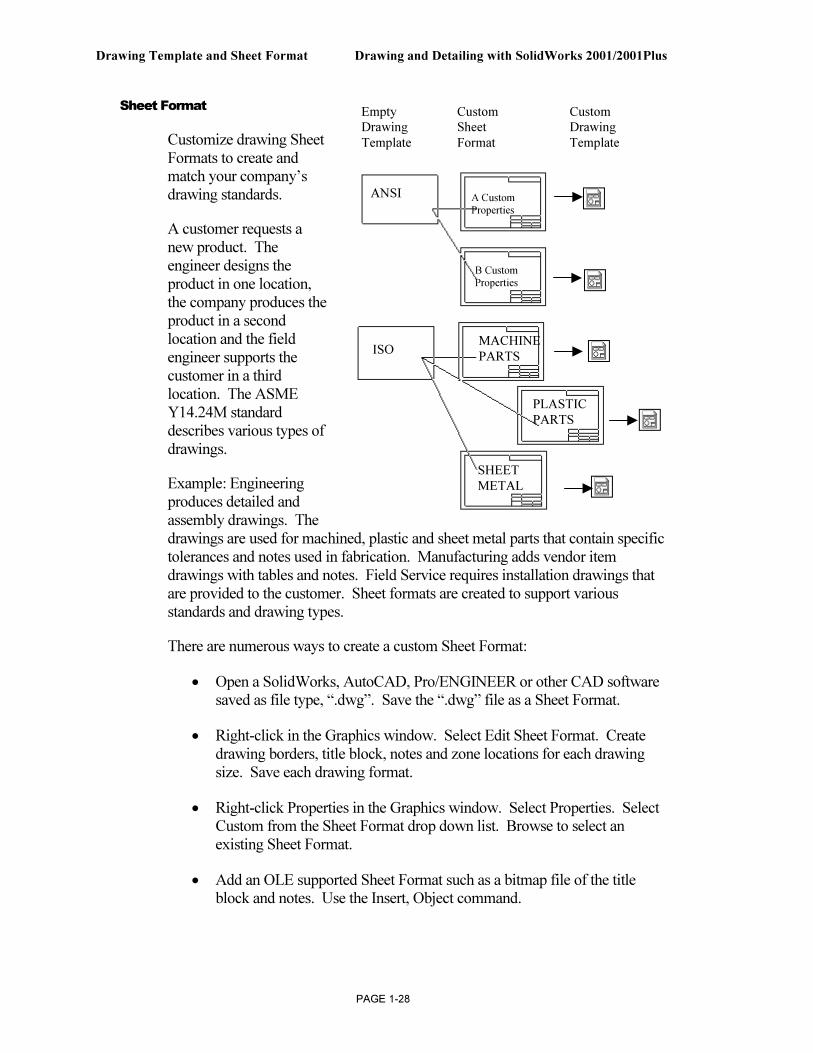
Sheet Format
Customize drawing Sheet Formats to create and match your company’s drawing standards.
A customer requests a new product. The engineer designs the product in one location, the company produces the product in a second location and the field engineer supports the customer in a third location. The ASME Y14.24M standard describes various types of drawings.
Example: Engineering produces detailed and assembly drawings. The drawings are used for machined, plastic and sheet metal parts that contain specific tolerances and notes used in fabrication. Manufacturing adds vendor item drawings with tables and notes. Field Service requires installation drawings that are provided to the customer. Sheet formats are created to support various standards and drawing types.
There are numerous ways to create a custom Sheet Format:
• Open a SolidWorks, AutoCAD, Pro/ENGINEER or other CAD software saved as file type, “.dwg”. Save the “.dwg” file as a Sheet Format.
• Right-click in the Graphics window. Select Edit Sheet Format. Create drawing borders, title block, notes and zone locations for each drawing size. Save each drawing format.
• Right-click Properties in the Graphics window. Select Properties. Select Custom from the Sheet Format drop down list. Browse to select an existing Sheet Format.
• Add an OLE supported Sheet Format such as a bitmap file of the title block and notes. Use the Insert, Object command.
ANSI
ISO
A Custom
Properties
B Custom
Properties
MACHINE
PARTS
PLASTIC
PARTS
SHEET
METAL
Empty Custom Custom
Drawing Sheet Drawing
Template Format Template
Drawing and Detailing with SolidWorks 2001/2001Plus Drawing Template and Sheet Format
PAGE 1-29
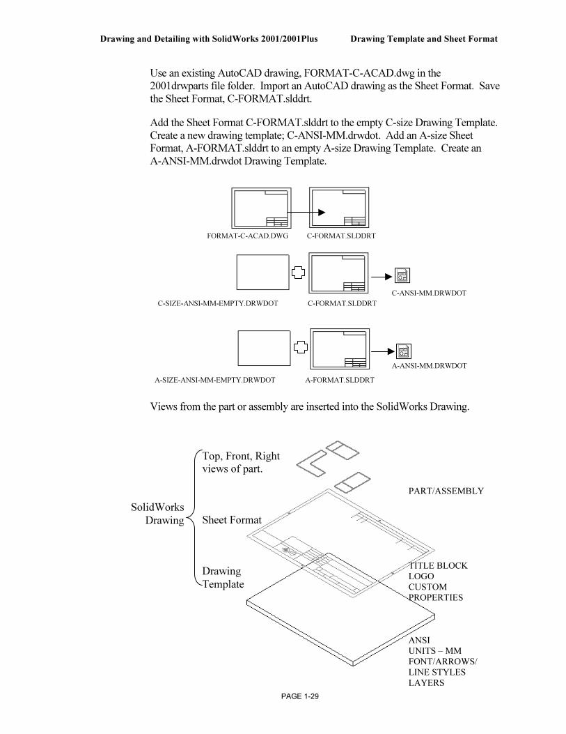
Use an existing AutoCAD drawing, FORMAT-C-ACAD.dwg in the 2001drwparts file folder. Import an AutoCAD drawing as the Sheet Format. Save the Sheet Format, C-FORMAT.slddrt.
Add the Sheet Format C-FORMAT.slddrt to the empty C-size Drawing Template. Create a new drawing template; C-ANSI-MM.drwdot. Add an A-size Sheet Format, A-FORMAT.slddrt to an empty A-size Drawing Template. Create an A-ANSI-MM.drwdot Drawing Template.
Views from the part or assembly are inserted into the SolidWorks Drawing.
FORMAT-C-ACAD.DWG C-FORMAT.SLDDRT
C-SIZE-ANSI-MM-EMPTY.DRWDOT C-FORMAT.SLDDRT
A-SIZE-ANSI-MM-EMPTY.DRWDOT A-FORMAT.SLDDRT
C-ANSI-MM.DRWDOT
A-ANSI-MM.DRWDOT
Top, Front, Right views of part.
Sheet Format
Drawing
Template
SolidWorks
Drawing
PART/ASSEMBLY
TITLE BLOCK
LOGO
CUSTOM PROPERTIES
ANSI UNITS – MM
FONT/ARROWS/
LINE STYLES
LAYERS
Drawing Template and Sheet Format Drawing and Detailing with SolidWorks 2001/2001Plus
PAGE 1-30
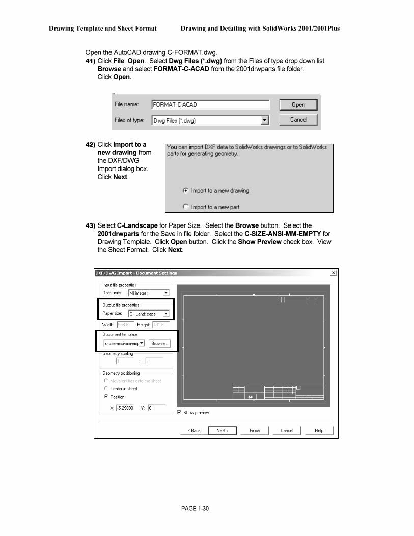
Open the AutoCAD drawing C-FORMAT.dwg. 41) Click File, Open. Select Dwg Files (*.dwg) from the Files of type drop down list.
Browse and select FORMAT-C-ACAD from the 2001drwparts file folder. Click Open.
42) Click Import to a new drawing from the DXF/DWG Import dialog box. Click Next.
43) Select C-Landscape for Paper Size. Select the Browse button. Select the 2001drwparts for the Save in file folder. Select the C-SIZE-ANSI-MM-EMPTY for Drawing Template. Click Open button. Click the Show Preview check box. View the Sheet Format. Click Next.
Drawing and Detailing with SolidWorks 2001/2001Plus Drawing Template and Sheet Format
PAGE 1-31
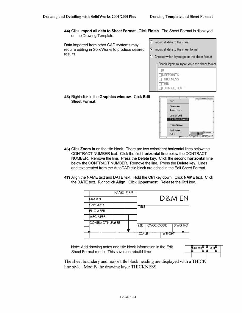
44) Click Import all data to Sheet Format. Click Finish. The Sheet Format is displayed on the Drawing Template.
Data imported from other CAD systems may require editing in SolidWorks to produce desired results.
45) Right-click in the Graphics window. Click Edit Sheet Format.
46) Click Zoom in on the title block. There are two coincident horizontal lines below the CONTRACT NUMBER text. Click the first horizontal line below the CONTRACT NUMBER. Remove the line. Press the Delete key. Click the second horizontal line below the CONTRACT NUMBER. Remove the line. Press the Delete key. Lines and text created from the AutoCAD title block are edited in the Edit Sheet Format.
47) Align the NAME text and DATE text. Hold the Ctrl key down. Click NAME text. Click the DATE text. Right-click Align. Click Uppermost. Release the Ctrl key.
Note: Add drawing notes and title block information in the Edit Sheet Format mode. This saves on rebuild time.
The sheet boundary and major title block heading are displayed with a THICK line style. Modify the drawing layer THICKNESS.
Drawing Template and Sheet Format Drawing and Detailing with SolidWorks 2001/2001Plus
PAGE 1-32
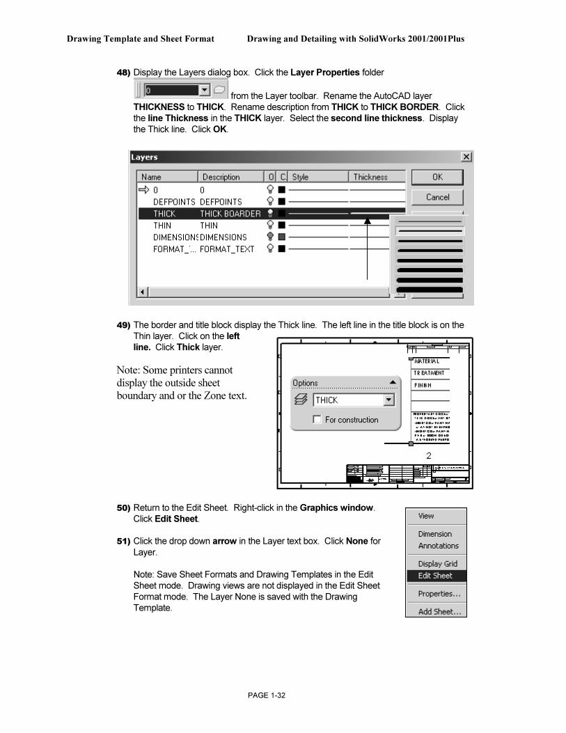
48) Display the Layers dialog box. Click the Layer Properties folder
from the Layer toolbar. Rename the AutoCAD layer THICKNESS to THICK. Rename description from THICK to THICK BORDER. Click the line Thickness in the THICK layer. Select the second line thickness. Display the Thick line. Click OK.
49) The border and title block display the Thick line. The left line in the title block is on the Thin layer. Click on the left line. Click Thick layer.
Note: Some printers cannot display the outside sheet boundary and or the Zone text.
50) Return to the Edit Sheet. Right-click in the Graphics window. Click Edit Sheet.
51) Click the drop down arrow in the Layer text box. Click None for Layer.
Note: Save Sheet Formats and Drawing Templates in the Edit Sheet mode. Drawing views are not displayed in the Edit Sheet Format mode. The Layer None is saved with the Drawing Template.
Drawing and Detailing with SolidWorks 2001/2001Plus Drawing Template and Sheet Format
PAGE 1-33
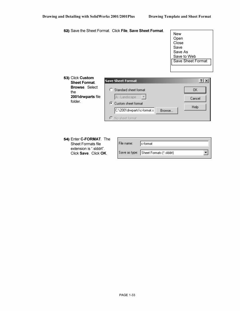
52) Save the Sheet Format. Click File, Save Sheet Format.
53) Click Custom
Sheet Format. Browse. Select the 2001drwparts file folder.
54) Enter C-FORMAT. The
Sheet Formats file extension is “.slddrt”. Click Save. Click OK.
New Open Close Save Save As Save to Web Save Sheet Format
Drawing Template and Sheet Format Drawing and Detailing with SolidWorks 2001/2001Plus
PAGE 1-34
Title Block Notes and Properties
Title blocks contain vital part and assembly information. Each company creates a unique version of a title block. Most title blocks contain the following type of information:
Company Name/Logo Part number
Part name Drawing number
Drawing description Revision number
Sheet number Material & finish
Tolerance Drawing scale
Sheet size Revision block
CAD file name Engineering Change Orders
Quantity required Drawn by
Checked by Approved by
A title block is normally located in the lower right hand corner of the drawing. You need to be in the Edit Sheet Format mode to modify the Sheet Format text, lines or title block information. You need to be in the Edit Sheet mode to insert model views. Edit Sheet and Edit Sheet Format are the two major design modes used to develop a drawing.
The Edit Sheet Format mode provides the ability to:
• Create or change the title block size and text headings
• Incorporate a logo
• Add drawing, design or company text, and Custom Properties
The Edit Sheet mode provides the ability to:
• Add or modify views
• Add or modify dimensions
• Add or modify text
Notes can be created or modified in a title block. Notes can also be linked to SolidWorks Properties and Custom Properties. Linked notes reflect information in a title block such as file name, sheet name and sheet number.
Drawing and Detailing with SolidWorks 2001/2001Plus Drawing Template and Sheet Format
PAGE 1-35
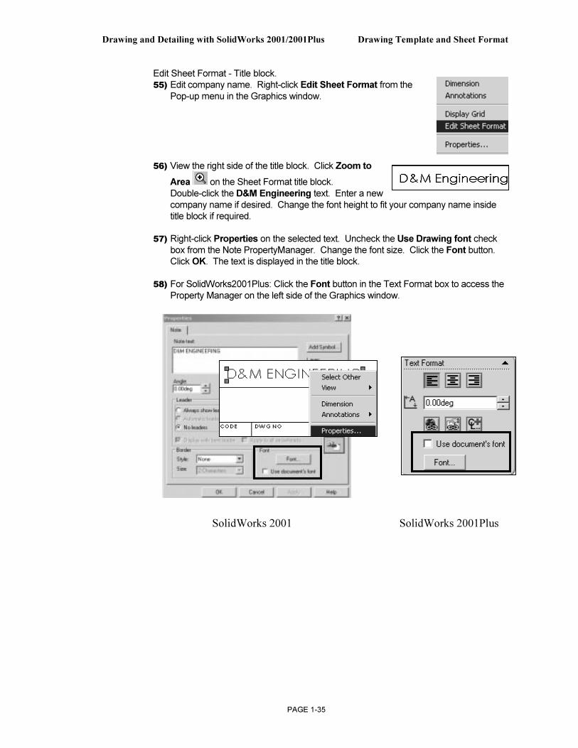
Edit Sheet Format - Title block. 55) Edit company name. Right-click Edit Sheet Format from the
Pop-up menu in the Graphics window.
56) View the right side of the title block. Click Zoom to
Area on the Sheet Format title block. Double-click the D&M Engineering text. Enter a new company name if desired. Change the font height to fit your company name inside title block if required.
57) Right-click Properties on the selected text. Uncheck the Use Drawing font check box from the Note PropertyManager. Change the font size. Click the Font button. Click OK. The text is displayed in the title block.
58) For SolidWorks2001Plus: Click the Font button in the Text Format box to access the Property Manager on the left side of the Graphics window.
SolidWorks 2001 SolidWorks 2001Plus
Drawing Template and Sheet Format Drawing and Detailing with SolidWorks 2001/2001Plus
PAGE 1-36
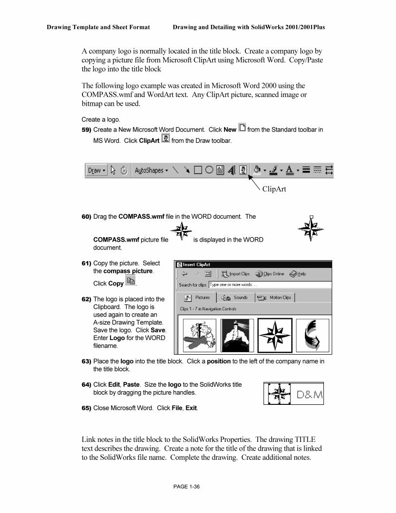
A company logo is normally located in the title block. Create a company logo by copying a picture file from Microsoft ClipArt using Microsoft Word. Copy/Paste the logo into the title block
The following logo example was created in Microsoft Word 2000 using the COMPASS.wmf and WordArt text. Any ClipArt picture, scanned image or bitmap can be used.
Create a logo.
59) Create a New Microsoft Word Document. Click New from the Standard toolbar in
MS Word. Click ClipArt from the Draw toolbar.
60) Drag the COMPASS.wmf file in the WORD document. The
COMPASS.wmf picture file is displayed in the WORD
document.
61) Copy the picture. Select the compass picture.
Click Copy .
62) The logo is placed into the Clipboard. The logo is used again to create an A-size Drawing Template. Save the logo. Click Save. Enter Logo for the WORD filename.
63) Place the logo into the title block. Click a position to the left of the company name in the title block.
64) Click Edit, Paste. Size the logo to the SolidWorks title
block by dragging the picture handles.
65) Close Microsoft Word. Click File, Exit.
Link notes in the title block to the SolidWorks Properties. The drawing TITLE text describes the drawing. Create a note for the title of the drawing that is linked to the SolidWorks file name. Complete the drawing. Create additional notes.
ClipArt
Drawing and Detailing with SolidWorks 2001/2001Plus Drawing Template and Sheet Format
PAGE 1-37
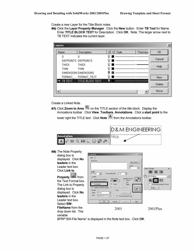
Create a new Layer for the Title Block notes. 66) Click the Layer Property Manager. Click the New button. Enter TB Text for Name.
Enter TITLE BLOCK TEXT for Description. Click OK. Note: The larger arrow next to TB TEXT indicates the current layer.
Create a Linked Note.
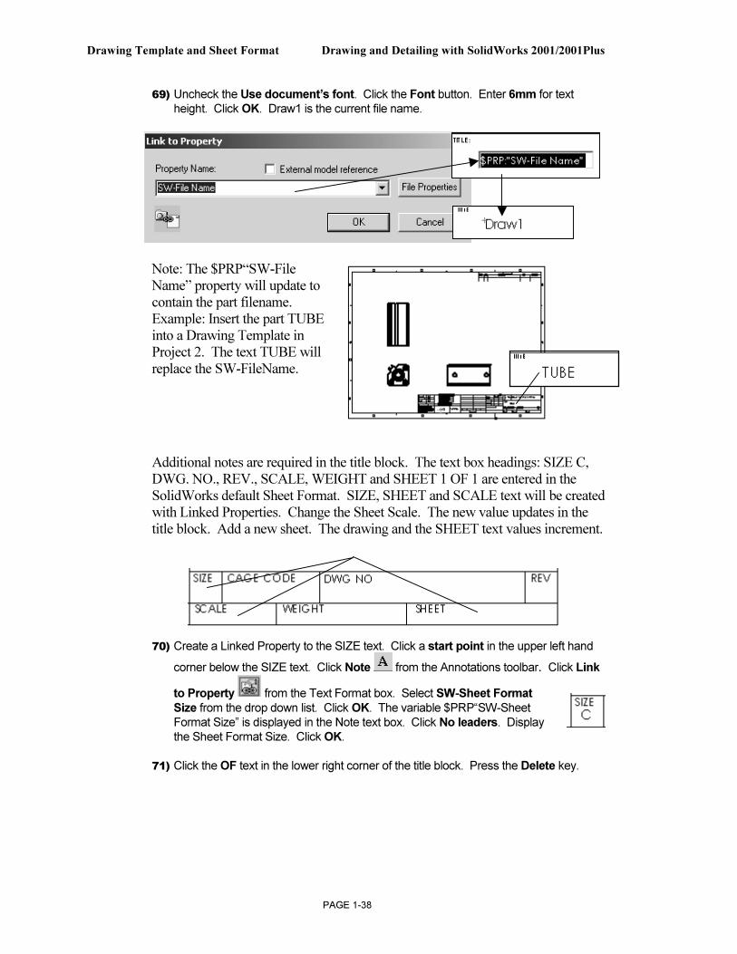
67) Click Zoom to Area on the TITLE section of the title block. Display the Annoations toolbar. Click View, Toolbars, Annotations. Click a start point to the
lower right the TITLE text. Click Note from the Annotations toolbar.
68) The Note Property dialog box is displayed. Click No leaders in the Leader text box. Click Link to
Property from
the Text Format box. The Link to Property dialog box is displayed. Click No leaders in the Leader text box. Select SW-
FileName from the drop down list. The variable $PRP“SW-File Name” is displayed in the Note text box. Click OK.
2001 2001Plus
Drawing Template and Sheet Format Drawing and Detailing with SolidWorks 2001/2001Plus
PAGE 1-38
69) Uncheck the Use document’s font. Click the Font button. Enter 6mm for text height. Click OK. Draw1 is the current file name.
Note: The $PRP“SW-File Name” property will update to contain the part filename. Example: Insert the part TUBE into a Drawing Template in Project 2. The text TUBE will replace the SW-FileName.
Additional notes are required in the title block. The text box headings: SIZE C, DWG. NO., REV., SCALE, WEIGHT and SHEET 1 OF 1 are entered in the SolidWorks default Sheet Format. SIZE, SHEET and SCALE text will be created with Linked Properties. Change the Sheet Scale. The new value updates in the title block. Add a new sheet. The drawing and the SHEET text values increment.
70) Create a Linked Property to the SIZE text. Click a start point in the upper left hand
corner below the SIZE text. Click Note from the Annotations toolbar. Click Link
to Property from the Text Format box. Select SW-Sheet Format
Size from the drop down list. Click OK. The variable $PRP“SW-Sheet Format Size” is displayed in the Note text box. Click No leaders. Display the Sheet Format Size. Click OK.
71) Click the OF text in the lower right corner of the title block. Press the Delete key.
Drawing and Detailing with SolidWorks 2001/2001Plus Drawing Template and Sheet Format
PAGE 1-39
72) Combine Link Properties for the SHEET text. Click a start point in the upper left
hand corner below the SHEET text. Click Note from the Annotations toolbar.
Click No leaders. Click Link to Property from the Text Format box. Select SW-Current Sheet from the drop down list. Click OK. Enter the text OF. Click Link
to Property from the Text Format box. Select SW-Total
Sheets from the drop down list. The variable $PRP”SW-Sheet Format Size” is displayed in the Note text box. Display the Sheet Format Size. Click OK. The Current Sheet value and Total Sheets value change as additional sheets are added to the drawing.
73) Create a Linked Property to SCALE. Click a start point in the upper left hand corner
below the SCALE text. Click Note from the Annotations toolbar. Click Link to
Property from the Text Format box. Select SW-Sheet
Scale from the drop down list. Click OK. The variable $PRP “SW-Sheet Scale” is displayed in the Note text box. Click OK. The Sheet Scale value changes to reflect the sheet scale properties in the drawing.
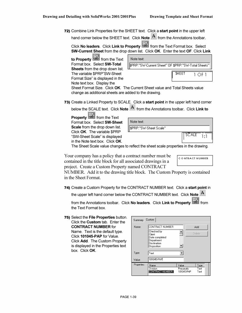
Your company has a policy that a contract number must be contained in the title block for all associated drawings in a project. Create a Custom Property named CONTRACT NUMBER. Add it to the drawing title block. The Custom Property is contained in the Sheet Format.
74) Create a Custom Property for the CONTRACT NUMBER text. Click a start point in
the upper left hand corner below the CONTRACT NUMBER text. Click Note
from the Annotations toolbar. Click No leaders. Click Link to Property from
the Text Format box.
75) Select the File Properties button. Click the Custom tab. Enter the CONTRACT NUMBER for Name. Text is the default type. Click 101045-PAP for Value. Click Add. The Custom Property is displayed in the Properties text box. Click OK.
Drawing Template and Sheet Format Drawing and Detailing with SolidWorks 2001/2001Plus
PAGE 1-40
76) Enter the CONTRACT
NUMBER in the Property Name text box. Click OK.
77) The Note text box displays: $PRP: “CONTRACT NUMBER”. Display 101045-PAP. Click OK.
78) Fit the drawing to the Graphics window. Press the f key.
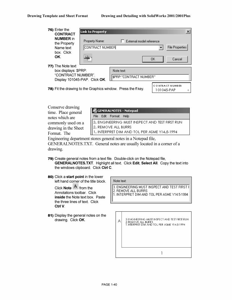
Conserve drawing time. Place general notes which are commonly used on a drawing in the Sheet Format. The Engineering department stores general notes in a Notepad file, GENERALNOTES.TXT. General notes are usually located in a corner of a drawing.
79) Create general notes from a text file. Double-click on the Notepad file, GENERALNOTES.TXT. Highlight all text. Click Edit, Select All. Copy the text into the windows clipboard. Click Ctrl C.
80) Click a start point in the lower left hand corner of the title block.
Click Note from the
Annotations toolbar. Click inside the Note text box. Paste the three lines of text. Click Ctrl V.
81) Display the general notes on the drawing. Click OK.
Drawing and Detailing with SolidWorks 2001/2001Plus Drawing Template and Sheet Format
PAGE 1-41
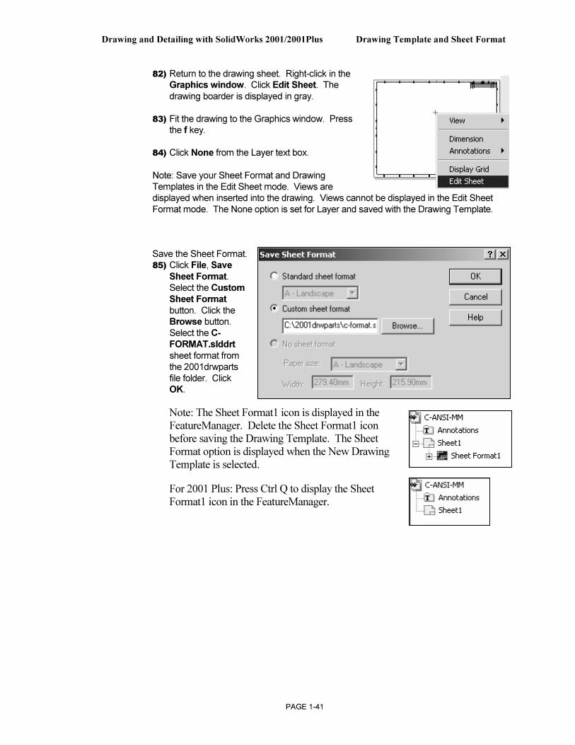
82) Return to the drawing sheet. Right-click in the Graphics window. Click Edit Sheet. The drawing boarder is displayed in gray.
83) Fit the drawing to the Graphics window. Press the f key.
84) Click None from the Layer text box.
Note: Save your Sheet Format and Drawing Templates in the Edit Sheet mode. Views are displayed when inserted into the drawing. Views cannot be displayed in the Edit Sheet Format mode. The None option is set for Layer and saved with the Drawing Template.
Save the Sheet Format. 85) Click File, Save
Sheet Format. Select the Custom
Sheet Format
button. Click the Browse button. Select the C-FORMAT.slddrt sheet format from the 2001drwparts file folder. Click OK.
Note: The Sheet Format1 icon is displayed in the FeatureManager. Delete the Sheet Format1 icon before saving the Drawing Template. The Sheet Format option is displayed when the New Drawing Template is selected.
For 2001 Plus: Press Ctrl Q to display the Sheet Format1 icon in the FeatureManager.
Drawing Template and Sheet Format Drawing and Detailing with SolidWorks 2001/2001Plus
PAGE 1-42
Create a new Drawing Template: C-ANSI-MM. Combine the Sheet Format and the empty Drawing Template.
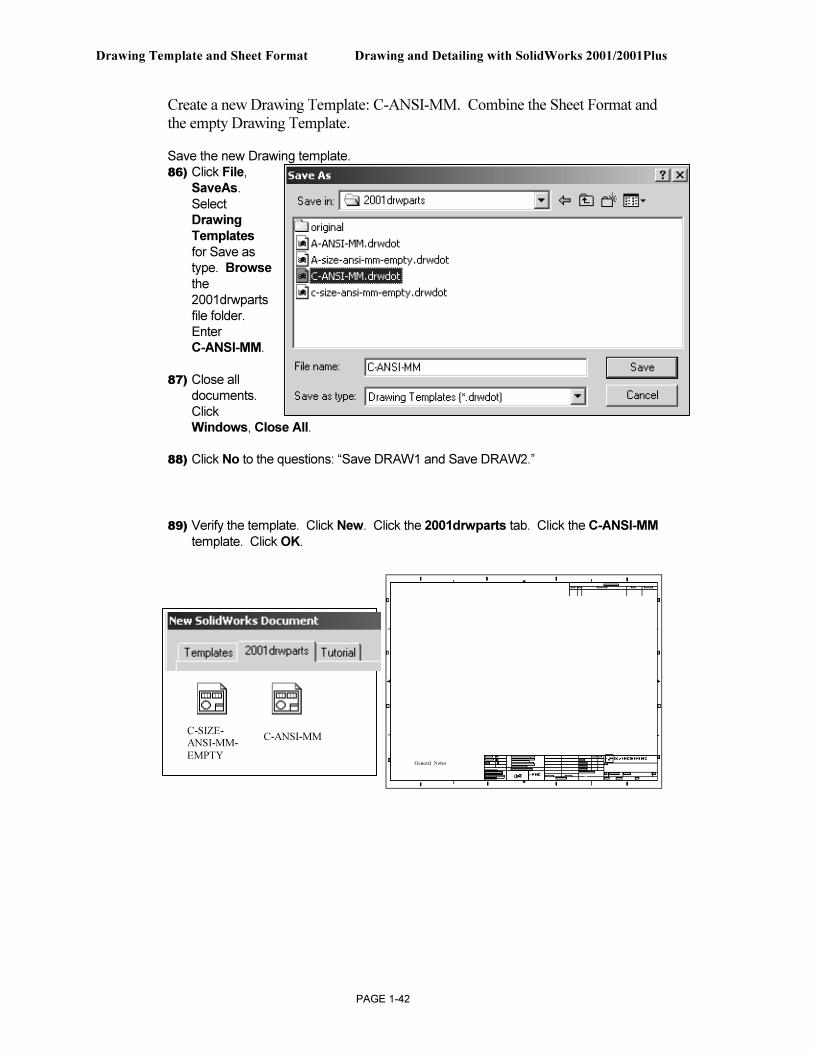
Save the new Drawing template. 86) Click File,
SaveAs. Select Drawing
Templates for Save as type. Browse the 2001drwparts file folder. Enter C-ANSI-MM.
87) Close all documents. Click Windows, Close All.
88) Click No to the questions: “Save DRAW1 and Save DRAW2.”
89) Verify the template. Click New. Click the 2001drwparts tab. Click the C-ANSI-MM template. Click OK.
C-SIZE-ANSI-MM-
EMPTY
C-ANSI-MM
General Notes
Drawing and Detailing with SolidWorks 2001/2001Plus Drawing Template and Sheet Format
PAGE 1-43
A - Size Drawing Template
Create an A size Drawing Template and an A size Sheet Format. Text size for an A-size drawing is the same as a C-size drawing. Create the A-size Drawing Template. Utilize the empty C-size Drawing Template. Create an A-ANSI-MM Drawing Template. Add an A-size Sheet Format.
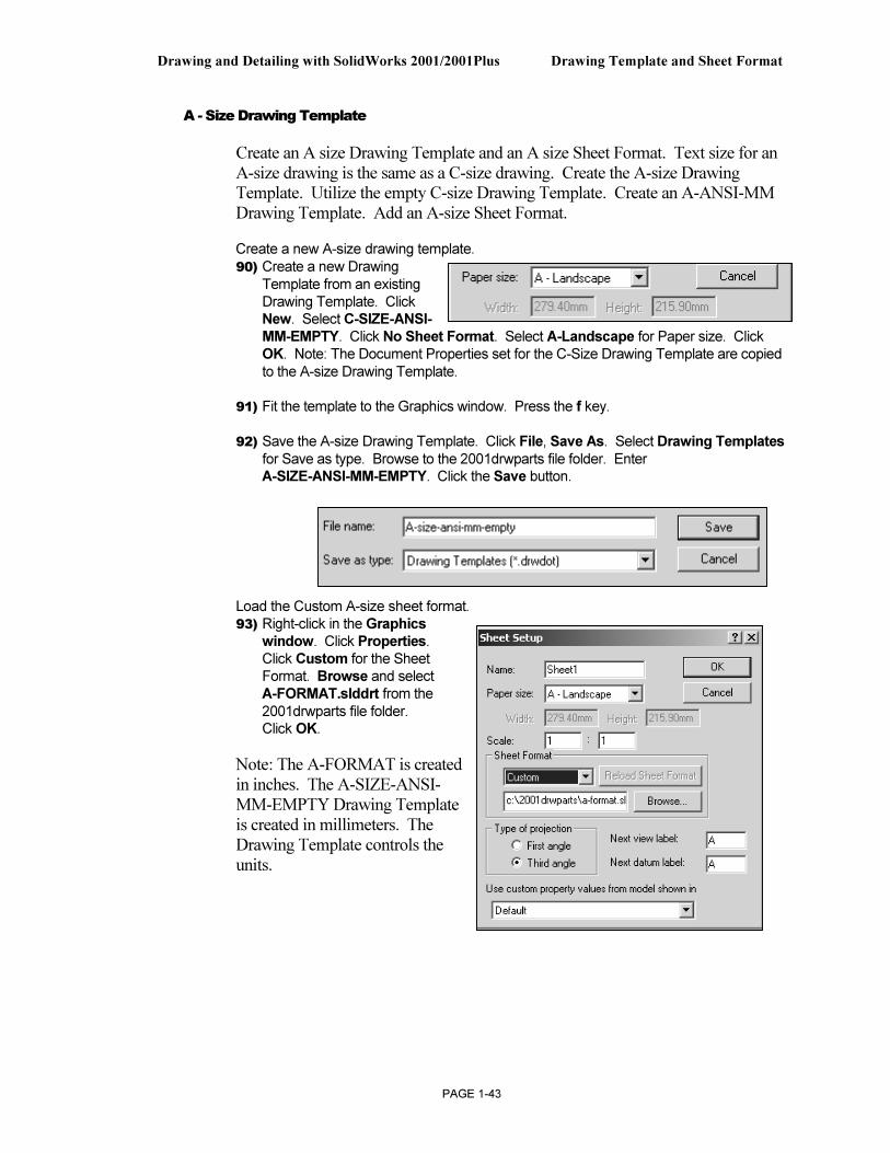
Create a new A-size drawing template. 90) Create a new Drawing
Template from an existing Drawing Template. Click New. Select C-SIZE-ANSI-MM-EMPTY. Click No Sheet Format. Select A-Landscape for Paper size. Click OK. Note: The Document Properties set for the C-Size Drawing Template are copied to the A-size Drawing Template.
91) Fit the template to the Graphics window. Press the f key.
92) Save the A-size Drawing Template. Click File, Save As. Select Drawing Templates for Save as type. Browse to the 2001drwparts file folder. Enter A-SIZE-ANSI-MM-EMPTY. Click the Save button.
Load the Custom A-size sheet format. 93) Right-click in the Graphics
window. Click Properties. Click Custom for the Sheet Format. Browse and select A-FORMAT.slddrt from the 2001drwparts file folder. Click OK.
Note: The A-FORMAT is created in inches. The A-SIZE-ANSI-MM-EMPTY Drawing Template is created in millimeters. The Drawing Template controls the units.
Drawing Template and Sheet Format Drawing and Detailing with SolidWorks 2001/2001Plus
PAGE 1-44
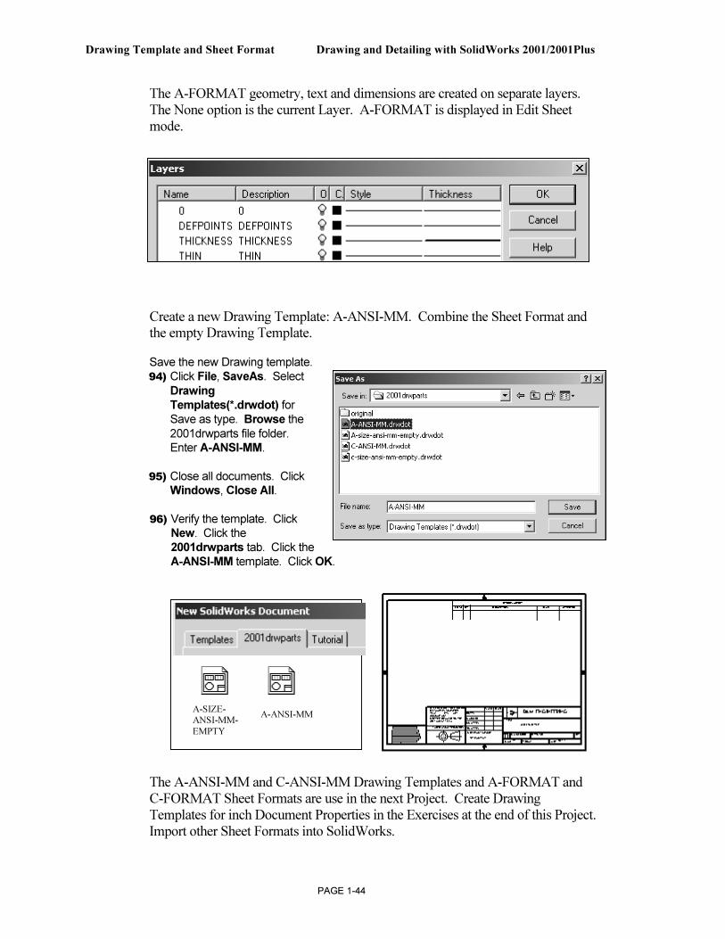
The A-FORMAT geometry, text and dimensions are created on separate layers. The None option is the current Layer. A-FORMAT is displayed in Edit Sheet mode.
Create a new Drawing Template: A-ANSI-MM. Combine the Sheet Format and the empty Drawing Template.
Save the new Drawing template. 94) Click File, SaveAs. Select
Drawing
Templates(*.drwdot) for Save as type. Browse the 2001drwparts file folder. Enter A-ANSI-MM.
95) Close all documents. Click Windows, Close All.
96) Verify the template. Click New. Click the 2001drwparts tab. Click the A-ANSI-MM template. Click OK.
The A-ANSI-MM and C-ANSI-MM Drawing Templates and A-FORMAT and C-FORMAT Sheet Formats are use in the next Project. Create Drawing Templates for inch Document Properties in the Exercises at the end of this Project. Import other Sheet Formats into SolidWorks.
A-SIZE-
ANSI-MM-
EMPTY
A-ANSI-MM
Drawing and Detailing with SolidWorks 2001/2001Plus Drawing Template and Sheet Format
PAGE 1-45
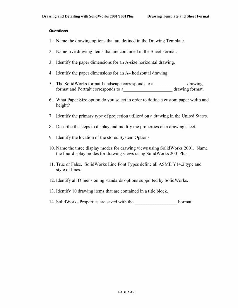
Questions
1. Name the drawing options that are defined in the Drawing Template.
2. Name five drawing items that are contained in the Sheet Format.
3. Identify the paper dimensions for an A-size horizontal drawing.
4. Identify the paper dimensions for an A4 horizontal drawing.
5. The SolidWorks format Landscape corresponds to a______________ drawing format and Portrait corresponds to a_____________________ drawing format.
6. What Paper Size option do you select in order to define a custom paper width and
height?
7. Identify the primary type of projection utilized on a drawing in the United States.
8. Describe the steps to display and modify the properties on a drawing sheet.
9. Identify the location of the stored System Options.
10. Name the three display modes for drawing views using SolidWorks 2001. Name the four display modes for drawing views using SolidWorks 2001Plus.
11. True or False. SolidWorks Line Font Types define all ASME Y14.2 type and style of lines.
12. Identify all Dimensioning standards options supported by SolidWorks.
13. Identify 10 drawing items that are contained in a title block.
14. SolidWorks Properties are saved with the __________________ Format.
Drawing Template and Sheet Format Drawing and Detailing with SolidWorks 2001/2001Plus
PAGE 1-46
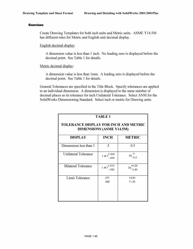
Exercises
Create Drawing Templates for both inch units and Metric units. ASME Y14.5M has different rules for Metric and English unit decimal display.
English decimal display:
A dimension value is less than 1 inch. No leading zero is displayed before the decimal point. See Table 1 for details.
Metric decimal display:
A dimension value is less than 1mm. A leading zero is displayed before the decimal point. See Table 1 for details.
General Tolerances are specified in the Title Block. Specify tolerances are applied to an individual dimension. A dimension is displayed to the same number of decimal places as its tolerance for inch Unilateral Tolerance. Select ANSI for the SolidWorks Dimensioning Standard. Select inch or metric for Drawing units.
TABLE 1
TOLERANCE DISPLAY FOR INCH AND METRIC
DIMENSIONS (ASME Y14.5M)
DISPLAY INCH METRIC
Dimensions less than 1 .5 0.5
Unilateral Tolerance
Bilateral Tolerance
Limit Tolerance
Drawing and Detailing with SolidWorks 2001/2001Plus Drawing Template and Sheet Format
PAGE 1-47
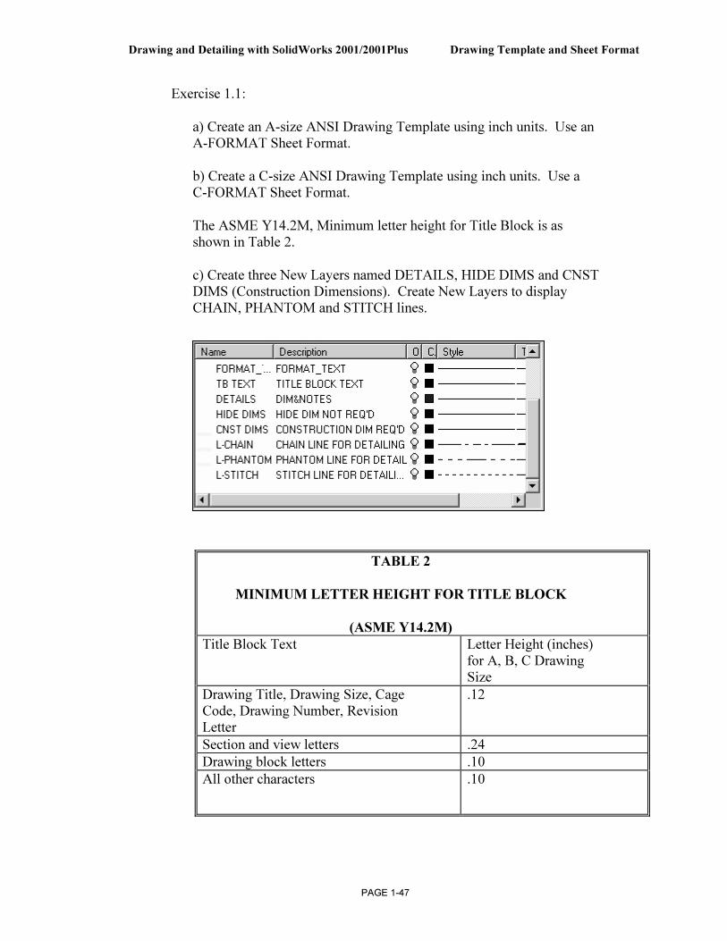
Exercise 1.1:
a) Create an A-size ANSI Drawing Template using inch units. Use an A-FORMAT Sheet Format.
b) Create a C-size ANSI Drawing Template using inch units. Use a C-FORMAT Sheet Format.
The ASME Y14.2M, Minimum letter height for Title Block is as shown in Table 2.
c) Create three New Layers named DETAILS, HIDE DIMS and CNST DIMS (Construction Dimensions). Create New Layers to display CHAIN, PHANTOM and STITCH lines.
TABLE 2
MINIMUM LETTER HEIGHT FOR TITLE BLOCK
(ASME Y14.2M)
Title Block Text Letter Height (inches) for A, B, C Drawing Size
Drawing Title, Drawing Size, Cage Code, Drawing Number, Revision Letter
.12
Section and view letters .24
Drawing block letters .10
All other characters .10
Drawing Template and Sheet Format Drawing and Detailing with SolidWorks 2001/2001Plus
PAGE 1-48
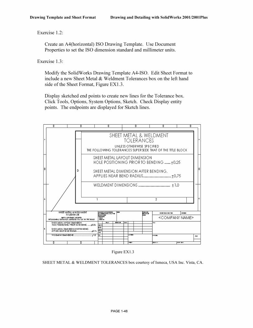
Exercise 1.2:
Create an A4(horizontal) ISO Drawing Template. Use Document Properties to set the ISO dimension standard and millimeter units.
Exercise 1.3:
Modify the SolidWorks Drawing Template A4-ISO. Edit Sheet Format to include a new Sheet Metal & Weldment Tolerances box on the left hand side of the Sheet Format, Figure EX1.3.
Display sketched end points to create new lines for the Tolerance box. Click Tools, Options, System Options, Sketch. Check Display entity points. The endpoints are displayed for Sketch lines.
Figure EX1.3
SHEET METAL & WELDMENT TOLERANCES box courtesy of Ismeca, USA Inc. Vista, CA.
Drawing and Detailing with SolidWorks 2001/2001Plus Drawing Template and Sheet Format
PAGE 1-49
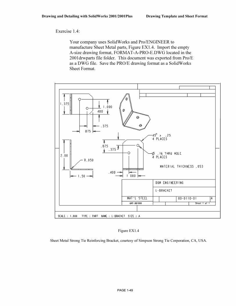
Exercise 1.4:
Your company uses SolidWorks and Pro/ENGINEER to manufacture Sheet Metal parts, Figure EX1.4. Import the empty A-size drawing format, FORMAT-A-PRO-E.DWG located in the 2001drwparts file folder. This document was exported from Pro/E as a DWG file. Save the PRO/E drawing format as a SolidWorks Sheet Format.
Figure EX1.4
Sheet Metal Strong Tie Reinforcing Bracket, courtesy of Simpson Strong Tie Corporation, CA, USA.
Drawing Template and Sheet Format Drawing and Detailing with SolidWorks 2001/2001Plus
PAGE 1-50
Exercise 1.5:
You require AutoCAD to perform Exercise 1.5. Your company uses SolidWorks and AutoCAD. Open an A-size drawing template from AutoCAD. Review the Dimension Variables (DIMVARS) in AutoCAD. Record the DIMSTATUS for the following variables:
DIMTXSTY Dimensioning Text Style
DIMASZ Arrow size
DIMCEN Center Mark size
DIMDEC Decimal Places
DIMTDEC Tolerance Decimal Places
DIMTXT Text Height
DIMDLI Space between dimension lines for Baseline dimensioning
Identify the corresponding values in SolidWorks Document Properties to contain the AutoCAD dimension variables.
For 2001Plus: Favorite dimension style settings are defined for a particular dimension. Favorite dimension styles are applied to other dimensions on the drawing, part and assembly documents. The styles are accessed through the Dimension PropertyManager.
Note: Early AutoCAD drawing formats contain fonts not supported in a Windows NT/2000 environment. These fonts imported into SolidWorks will be misaligned in the Sheet Format. Modify older AutoCAD formats to a True Type Font in SolidWorks.