47491c rkey k2200 user's guide -...
TRANSCRIPT

ENUser Guide
Readykey Controllers
K2200 Series

K2200 Series | User Guide | Contents EN | 2
Bosch Security Systems | 7/03 | 17376 v1.1 / 47491C
Contents1.0 Introduction................................................... 41.1 Manual Organization ..................................... 41.2 Other Literature Referenced ......................... 41.3 Documentation Conventions ........................ 41.3.1 Type Styles Used in this Manual .................. 41.3.2 Tips, Important Notes, Cautions and
Warnings.......................................................... 41.4 Abbreviations Used........................................ 51.5 Listings and Approval .................................... 61.5.1 FCC Notice ..................................................... 61.5.2 UL Listing........................................................ 61.5.3 HEALTH AND SAFETY ............................. 61.5.4 CABLING ....................................................... 62.0 System Overview ......................................... 72.1 Specifications................................................... 72.2 How the System Works ................................. 82.2.1 Readers ............................................................ 82.2.2 Door Controllers............................................. 82.2.1 Administration Software ................................ 93.0 Administering the System........................ 103.1 Using the Faceplate ...................................... 103.1.1 Editor Mode .................................................. 103.1.2 Editor Key Administration .......................... 103.1.3 Using Editor Mode....................................... 123.1.4 Entering Editor Mode .................................. 133.1.5 Command Prompt - CMD .......................... 133.1.6 Leaving Editor Mode ................................... 133.1.7 Panel Keyboard ............................................ 134.0 Key Administration/ Access Control .... 174.1 Key Administration ...................................... 174.1.1 Personnel Database ...................................... 174.1.2 Adding Keys – The A Command............... 184.1.3 Deleting (Voiding) Keys – The V Command
........................................................................ 184.1.4 Editing Keys – The E Command ............... 194.1.5 PIN Codes – The N Command.................. 204.2 Controlling Access........................................ 204.2.1 Access Code Overview................................ 214.2.2 Organizing Access Codes ............................ 214.2.3 How to Create Access Codes...................... 224.2.4 Access Levels – The AL Command........... 224.2.5 Time Profiles ................................................. 234.2.6 Access Codes – The AC Command .......... 234.2.7 Holidays – The HR and HP Commands .. 244.3 Time Profiles ................................................. 244.3.1 How Time Profiles Work ............................ 254.3.2 Examples ....................................................... 254.3.3 The PR Command ....................................... 264.3.4 Creating a Time Profile – The T Command
........................................................................ 26
4.4 System Administration................................. 274.4.1 Changing the Date and Time – The C
Command...................................................... 274.4.2 Manual Lock/Unlock – The L Command 275.0 Displays, Alarms, and Printing ............... 285.1 Normal Operation........................................ 285.1.1 Master Controller ......................................... 285.1.2 Slave Controller............................................ 285.1.3 Master and Slave .......................................... 285.2 Alarms............................................................ 285.2.1 Accepted Alarms .......................................... 285.2.2 Alarm Activations......................................... 285.2.3 Uncleared Alarms......................................... 315.2.4 Communication Errors ................................ 315.3 Other System Messages ............................... 315.3.1 Update Progress............................................ 315.3.2 Download Progress ...................................... 315.4 Using the Printer........................................... 315.4.1 Setting up the Printer ................................... 315.4.2 On-Line Transaction Printing ..................... 325.4.3 High-Priority Events..................................... 325.4.4 Printing Reports............................................ 325.5 Printer Reports.............................................. 325.5.1 Print Report – The P1 to P9 Commands .. 325.5.2 Header – The HE Command ..................... 406.0 Installer Commands .................................. 426.1 The D Command ......................................... 426.1.1 Lock Release Time....................................... 426.1.2 Door Open Time.......................................... 426.1.3 Door Monitoring .......................................... 426.1.4 Time Profile .................................................. 426.1.5 Door Name ................................................... 446.1.6 PIN Reader Time Profile............................. 446.1.7 Using the D Command................................ 456.2 Alarm Event Manager and Relay Outputs 466.2.1 Overview ....................................................... 466.2.2 Identiying Modules, Inputs and Relays ..... 466.2.3 Alarm Module Relays.................................. 476.2.4 Alarm Module Programming – The MR and
MS Commands............................................. 476.2.5 Relay Programming ..................................... 497.0 Troubleshooting ......................................... 517.1 End User Troubleshooting .......................... 517.1.1 Key Not Working......................................... 517.1.2 No Access to Editor ..................................... 537.1.3 Cannot Add/Delete Keys ............................ 54Appendix A: Transactions ..................................... 55A.1 List of Transactions ...................................... 55A.2 High Priority Transactions .......................... 58Index 59
K2200 Series | User Guide | Figures EN | 3
Bosch Security Systems | 7/03 | 17376 v1.1 / 47491C
FiguresFigure 1: Failsafe Lock Wiring ............................... 6Figure 2: Components of a Readykey Access
Control System ........................................ 8Figure 3: Connecting Door Controllers ................ 9Figure 4: K2200 Faceplate .................................... 13Figure 5: Editor Example...................................... 15Figure 6: Sample System Layout ......................... 21Figure 7: Unauthorized Access/Anit-Tamper
Alarms .................................................... 29Figure 8: Door Controller Override Alarm........ 29Figure 9: Zone Alarm............................................ 29Figure 10: Duress Alarm......................................... 30Figure 11: Case Tamper Alarm.............................. 30Figure 12: Alarm Module Tamper Alarm ............ 30Figure 13: Sample P1 – Personnel Printout .......... 34Figure 14: Sample P2 – Personnel Printout .......... 35Figure 15: Sample P3 – Access Data Printout ...... 36Figure 16: Sample P4 - System Status Printout .... 37Figure 17: Sample P5 - Transaction Printout........ 38Figure 18: Sample P6 - System Set Up Printout... 39Figure 19: Sample P7 - Alarm Data Printout........ 39Figure 20: Sample P8 - Time Profile Printout ...... 40Figure 21: Sample P9 - Holiday Profile Printout.. 40Figure 22: Windows Based System Sheet 1Error!
Bookmark not defined.Figure 23: Windows-Based System Sheet 2Error!
Bookmark not defined.Figure 24: Standalone System ................................ 52Figure 25: No Access to Editor .............................. 53Figure 26: Cannot Add/Delete Keys..................... 54
Table of TablesTable 1: K2200 Series User Guide Organization 4Table 2: Other Literature Referenced.................. 4Table 3: Type Styles Used in Manual .................. 4Table 4: K2200 Series Specifications.................... 7Table 5: Editor Level Assignments..................... 11Table 6: Editor Level Calculations ..................... 11Table 7: Master Key Commands........................ 11Table 8: Navigation Keys .................................... 14Table 9: Display Altering Keys........................... 15Table 10: Door to Door Controller Association . 22Table 11: Access Level Examples......................... 23Table 12: Time Profile Effect ................................ 25Table 13: Time Period Examples ......................... 26Table 14: : Display Key ......................................... 31Table 15: Print Report Commands ...................... 33Table 16: System Status – Doors and Alarm Zones
................................................................. 37
Table 17: Reader and Lock Operation Settings –Mode 1 ................................................... 43
Table 18: Reader and Lock Operation Settings -Mode 2 ................................................... 44
Table 19: Lock Mode Options.............................. 45Table 20: Lock Mode 2 Options........................... 45Table 21: Zone Number ........................................ 46Table 22: Relay Defaults........................................ 47Table 23: Relay Numbers...................................... 48Table 24: Event Types ........................................... 49Table 25: LED StatusError! Bookmark not
defined.Table 26: Transactions ........................................... 55

K2200 Series | User Guide | 1.0 Introduction EN | 4
Bosch Security Systems | 7/03 | 17376 v1.1 / 47491C
1.0 Introduction1.1 Manual OrganizationThis manual is divided into seven sections with anappendix. A summary of each section and appendixis detailed in the table below.
Table 1: K2200 Series User GuideOrganization
Section Description1 Introduction2 System Overview – Basic overview of the
K2200 Series.3 Administrating the System – Information
and procedures on administrating aK2200 Series system.
4 Key Administration and Access Control –Covers administration of the personneldatabase, including adding/deleting keysand specifying Access Control functions.
5 Displays, Alarms and Printing - describesthe various displays and also covers theprinting options which are available
6 Installer Commands - describes thecommands used to configure the doorcontroller.
7 Troubleshooting – Common solutionsand procedures to rectify troubleshootingcon
AppendixA
Transactions - shows all the transactionsgenerated by the door controllers
1.2 Other Literature ReferencedThroughout this manual, references will be made toother documentation. See the following table for amore complete and detailed description of the K2200Series Controllers.
Table 2: Other Literature Referenced
Part Number
Name of DocumentBosch/
RadionicsPAC
Readykey K2200 SeriesController Installation Guide
46513 17375
1.3 Documentation ConventionsThese conventions are intended to call out importantfeatures, items, notes, cautions, and warnings that thereader should be aware of in reading this document.
1.3.1 Type Styles Used in this Manual
To help identify important items in the text, thefollowing type styles are used:
Table 3: Type Styles Used in Manual
Bold Text Usually indicates selections thatyou may use while programmingyour panel. May also indicate animportant fact that you should note.
Bold ItalicizedText
Denotes notes, cautions and/orwarnings.
Italicized Text Refers you to a drawing, table, orother section of this document, orto another document. Also used tosymbolize names for records thatyou will create.
Courier Text Indicates what may appear on thecommand center/keypad, orinternal printer.
[CAPITALIZEDTEXT]
Indicates a specific key on thedevice to be pressed.
On-ScreenButtons
Indicates a specific button thatappears on screen
File � New This is used to describe the path ingetting to a specific sub-menu orcommand in a Windows-basedapplication.Example: …select File•New tocreate a new
1.3.2 Tips, Important Notes, Cautions andWarnings
Throughout this document, helpful tips, importantnotes, cautions and warnings will be presented for thereader to keep in mind. These appear different fromthe rest of the text as follows;
Important Notes - should be heeded forsuccessful operation and programming.Also tips and shortcuts may be includedhere.
Caution - These caution the operator thatphysical damage to the program and/orequipment may occur.
Warning - These warn of the possibility ofphysical damage to the operator, programand/or equipment.

K2200 Series | User Guide | 1.0 Introduction EN | 5
Bosch Security Systems | 7/03 | 17376 v1.1 / 47491C
1.4 Abbreviations UsedThe following list of abbreviations are used throughout this manual.AC Access CodeAEM Alarm Event ManagerAVR Automatic Vehicle RecognitionBAT BatteryCH ChannelCLK ClockCMD CommandCNC Central Network ControllerCOM CommonCTS Clear To SendD/C Door ControllerDC Door ContactDL Down LoadDOS Disk Operating SystemDTR Delay Transmit/ReceiveDR DoorEMF Electro-Motive ForceFIFO First In First OutGND GroundHBC High Breaking CapacityID IdentityIP Input or Internet ProtocolLED Light Emitting DiodeLK LockLRT Lock Release TimeMOV Metal Oxide VaristorMS Alarm Module SensorsMS-DOS Microsoft Disk Operating SystemOVRD OverridePAL Primary Access LevelPB Pass BackPB-TIM Pass Back TimeoutPBC Pass Back ControllerPC Personnel ComputerPIN Personal Identity NumberPINTP PIN Reader Time ProfileRDR ReaderRTE Request To ExitRTS Request To SendRX ReceiveSIG SignalTAMP TamperTP Time ProfileTX TransmitVCA Valid Code Accepted

K2200 Series | User Guide | 1.0 Introduction EN | 6
Bosch Security Systems | 7/03 | 17376 v1.1 / 47491C
1.5 Listings and Approval1.5.1 FCC Notice
This equipment generates and uses radio frequencyenergy. If not installed and used in accordance withthe manufacturer's instructions, it may causeinterference to radio and television reception. It hasbeen tested and found to comply with thespecifications Subpart F of Part 15 of FCC rules forField Disturbance Sensors. If this equipment causesinterference to radio or television reception - whichcan be determined by turning the equipment on andoff - the installer is encouraged to correct theinterference by one or more of the followingmeasures:
• Reorient the antenna of the radio/television,
• Connect the AC power cord to a different outletso the control panel and radio/television are ondifferent branch circuits,
• Relocate the control panel with respect to theradio/television.
If necessary, the installer should consult anexperienced radio/television technician for additionalsuggestions, or send for the "Interference Handbook"prepared by the Federal CommunicationsCommission. This booklet is available from the
U.S. Government Printing Office,Washington D.C. 20402,stock no. 004-000-00450-7.
FCC Registration Number: IDHM32Y6K2000
1.5.2 UL Listing
UL 294 - Access Control System Units
When installing the K2200 seriescontrollers the following should be noted:
1.5.3 HEALTH AND SAFETY
It must also comply with any local Fire, Health andSafety regulations. A secured door that may be partof an escape route from an area must be installedwith:
• A fail-safe lock (A). So that the door will bereleased if the power fails. Ideally a magneticlock should be used as these are less likely to jamor seize.
• A normally-closed break-glass or manual pull (B)in the lock supply wiring. So that in anemergency the fail-safe lock can be immediatelypowered down.
Figure 1: Failsafe Lock Wiring
BA
• The controller must be grounded.
• Disconnect both ac and battery power supplybefore working on the controller.
1.5.4 CABLING
The cabling used in the Readykey access controlsystems (six wire bus, reader cables, etc.) are notprone to electrical interference. However, you shouldavoid routing cable close to heavy load switchingcables and equipment. If this is unavoidable, crossthe cable at right angles every 3.3 to 6.6 ft (1 to 2 m)to reduce the interference.

K2200 Series | User Guide | 2.0 System Overview EN | 7
Bosch Security Systems | 7/03 | 17376 v1.1 / 47491C
2.0 System OverviewThis section briefly describes how a Readykey AccessControl System works and covers the basic systemcomponents:
• Readers.
• Door controllers.
• Administration system.
• Connecting door controllers to make a basicaccess system.
2.1 SpecificationsThis section details the system specification for astandalone system.
Table 4: K2200 Series Specifications
Access Points 16One master 4-door Readykey K2200or 2-door Readykey K1200controlling up to three slaves, a slavemay be 4-door Readykey K2200 or2-door Readykey K1200 controller.
Personnel 4000Editor Keys Master key plus 32 editor keys, each
with optional password and editorlevel.
Access Codes 128, comprising two access levels,each with a time profile.
Access Levels 128Time Profiles 128, each comprising 3 time periods
(max. 32 time periods).Holiday Profiles 24, each comprising 20 holiday
periods (max. 254 holiday periods).System Holidays 20, for controlling access on public
holidays.Transactions 2500 most recent transactions
stored in non-volatile memory.Zone Alarms 128, up to 32 per door controller
using alarm modules.Relay Outputs 4 on each door controller, plus 8 on
each alarm module. These may becontrolled by time profile or systemevent.
Alarms Unauthorized access, anti-tamper(on reader, alarm module and doorcontroller), door override, zone, PINreader duress.
Warning Door left openPrinter Output Continuous printing of system
events.9 different reports available ondemand.

K2200 Series | User Guide | 2.0 System Overview EN | 8
Bosch Security Systems | 7/03 | 17376 v1.1 / 47491C
2.2 How the System WorksAny Readykey access control system consists of threecomponents: readers, door controllers and anadministration system.
The readers will detect the unique code in a key andpass it directly to the door controller. The doorcontroller compares the code to the informationstored in its memory and, if the key is valid, willoperate the lock and send a report to theadministration system. The administration system isthe means by which the user programs the system(who is allowed where and when, etc.) and alsowhere events are reported.
In the case of the Readykey K2200 and ReadykeyK1200, the administration system is built in to thedoor controller and uses the keypad, display andreader on the front panel. As an option a printer canbe connected to the system that reports events asthey happen, and can also produce listings ofpersonnel, system setup, past events, etc.
Figure 2: Components of a Readykey Access Control System
Administration System
Door Controller
Reader
Lock
Key
< Key Code
Lock Output >
< Transactions
Updates >
Key Code
Access Decision
2.2.1 Readers
A reader is a device, usually mounted close to thedoor, that detects the unique code in a key or cardand passes it to the door controller where the accessdecision is made. There are several types of readersuitable for different purposes and environments.Below are some of the special types of readingdevices.
Request to Exit Switch
Sometimes a reader is used on both sides of a door,controlling both entry and exit from an area.Normally, however, a Request to Exit motion orbutton is used to open a door from the secure side.This switch, mounted close to the door, when pressedsends a signal to the door controller to release thelock. Of course, anyone can press the switch to openthe door when leaving, therefore no identity of theperson can be recorded.
2.2.2 Door Controllers
The door controller is the heart of the access controlsystem; its main functions are to:
• Decide whether a person has access at aparticular door and at a particular time.
• Provide power to operate the lock.
• Monitor doors for unauthorized access or leftopen conditions.
• Automatically lock and unlock doors at certaintimes.
• Detect tamper conditions at the reader or at thecontroller.
• Monitor any alarm modules for extra alarminputs.
• Operate relays on the door controller itself or onan alarm module.
The Readykey K2200 may have 4 readers connected,the Readykey K1200 may have 2 readers connected.In all other respects, both door controllers areidentical.
K2200 Series | User Guide | 2.0 System Overview EN | 9
Bosch Security Systems | 7/03 | 17376 v1.1 / 47491C
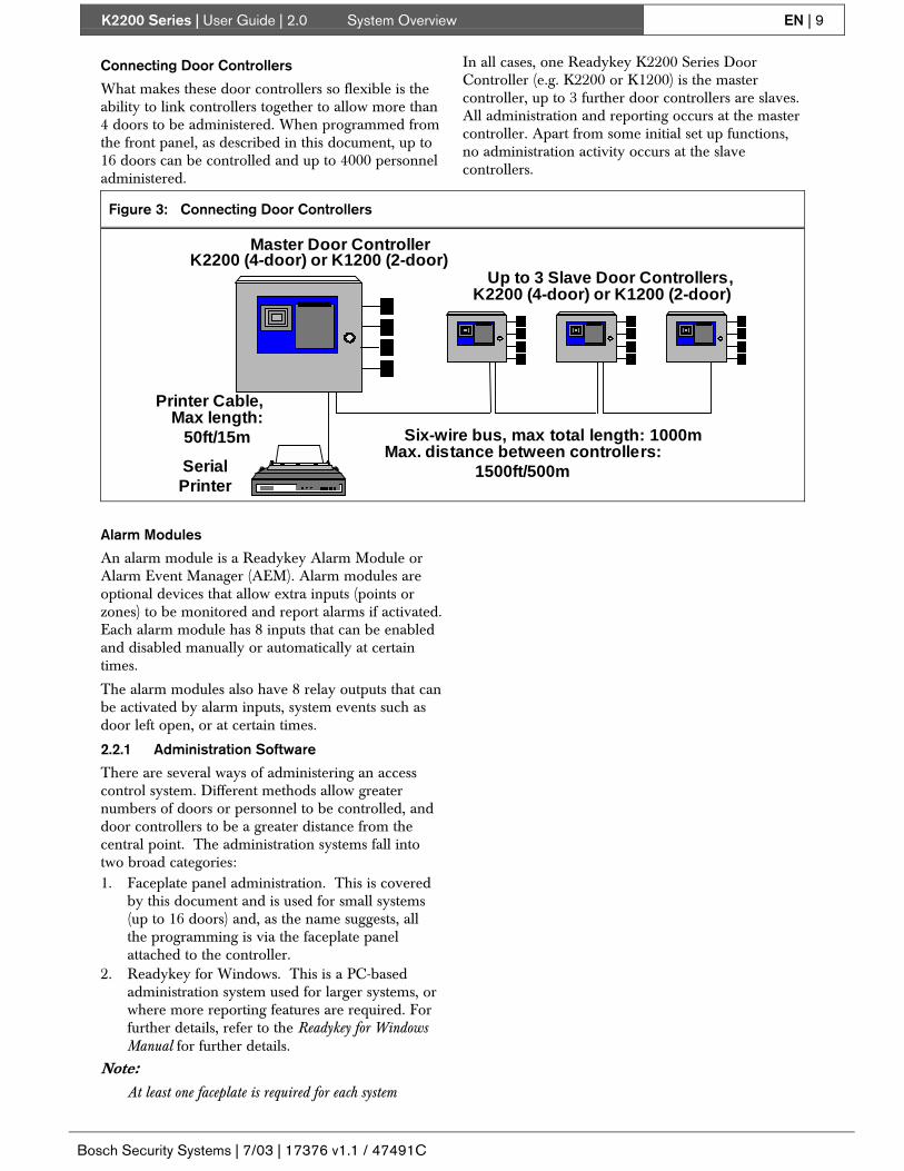
Connecting Door Controllers
What makes these door controllers so flexible is theability to link controllers together to allow more than4 doors to be administered. When programmed fromthe front panel, as described in this document, up to16 doors can be controlled and up to 4000 personneladministered.
In all cases, one Readykey K2200 Series DoorController (e.g. K2200 or K1200) is the mastercontroller, up to 3 further door controllers are slaves.All administration and reporting occurs at the mastercontroller. Apart from some initial set up functions,no administration activity occurs at the slavecontrollers.
Figure 3: Connecting Door Controllers
Master Door Controller
Up to 3 Slave Door Controllers,
Serial Printer
Printer Cable,
K2200 (4-door) or K1200 (2-door)
Max length: 50ft/15m Six-wire bus, max total length: 1000m
Max. distance between controllers: 1500ft/500m
K2200 (4-door) or K1200 (2-door)
Alarm Modules
An alarm module is a Readykey Alarm Module orAlarm Event Manager (AEM). Alarm modules areoptional devices that allow extra inputs (points orzones) to be monitored and report alarms if activated.Each alarm module has 8 inputs that can be enabledand disabled manually or automatically at certaintimes.
The alarm modules also have 8 relay outputs that canbe activated by alarm inputs, system events such asdoor left open, or at certain times.
2.2.1 Administration Software
There are several ways of administering an accesscontrol system. Different methods allow greaternumbers of doors or personnel to be controlled, anddoor controllers to be a greater distance from thecentral point. The administration systems fall intotwo broad categories:1. Faceplate panel administration. This is covered
by this document and is used for small systems(up to 16 doors) and, as the name suggests, allthe programming is via the faceplate panelattached to the controller.
2. Readykey for Windows. This is a PC-basedadministration system used for larger systems, orwhere more reporting features are required. Forfurther details, refer to the Readykey for WindowsManual for further details.
Note:At least one faceplate is required for each system
K2200 Series | User Guide | 3.0 Administering the System EN | 10
Bosch Security Systems | 7/03 | 17376 v1.1 / 47491C
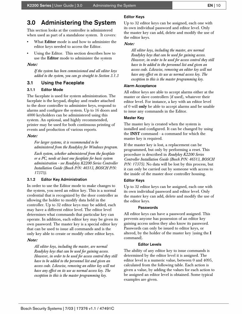
3.0 Administering the SystemThis section looks at the controller is administeredwhen used as part of a standalone system. It covers:
• What Editor mode is and how to administer theeditor keys needed to access the Editor.
• Using the Editor. This section describes how touse the Editor mode to administer the system
Note:If the system has been commissioned and all editor keysadded to the system, you can go straight to Section 3.1.3
3.1 Using the Faceplate3.1.1 Editor Mode
The faceplate is used for system administration. Thefaceplate is the keypad, display and reader attachedto the door controller to administer keys, respond toalarms and configure the system. Up to 16 doors and4000 keyholders can be administered using thissystem. An optional, and highly recommended,printer may be used for both continuous printing ofevents and production of various reports.
Note:For larger systems, it is recommended to beadministered from the Readykey for Windows program.
Each system, whether administered from the faceplateor a PC, needs at least one faceplate for basic systemadministration - see Readykey K2200 Series ControllerInstallation Guide (Bosch P/N: 46513, BOSCH P/N:17375).
3.1.2 Editor Key Administration
In order to use the Editor mode to make changes tothe system, you need an editor key. This is a normalcredential that is recognized by the door controller asallowing the holder to modify data held in thecontroller. Up to 32 editor keys may be added, eachmay have a different editor level. The editor leveldetermines what commands that particular key canoperate. In addition, each editor key may be given itsown password. The master key is a special editor keythat can be used to issue all commands and is theonly key able to create or modify other editor keys.
Note:All editor keys, including the master, are normalReadykey keys that can be used for gaining access.However, in order to be used for access control they stillhave to be added to the personnel list and given anaccess code. Likewise, removing an editor key will nothave any effect on its use as normal access key. Theexception to this is the master programming key.
Editor Keys
Up to 32 editor keys can be assigned, each one withits own individual password and editor level. Onlythe master key can add, delete and modify the use ofthe editor keys.
Note:All editor keys, including the master, are normalReadykey keys that can be used for gaining access.However, in order to be used for access control they stillhave to be added to the personnel list and given anaccess code. Likewise, removing an editor key will nothave any effect on its use as normal access key. Theexception to this is the master programming key.
Alarm Acceptance
All editor keys are able to accept alarms either at themaster or slave controllers (if used), whatever theireditor level. For instance, a key with an editor levelof 0 will only be able to accept alarms and be unableto issue any commands in the Editor.
Master Key
The master key is created when the system isinstalled and configured. It can be changed by usingthe INST command - a command for which themaster key is required.
If the master key is lost, a replacement can beprogrammed, but only by performing a reset. Thisprocedure is described in Readykey K2200 SeriesController Installation Guide (Bosch P/N: 46513, BOSCHP/N: 17375). No data will be lost by this process, butit can only be carried out by someone with access tothe inside of the master door controller housing.
Editor Keys
Up to 32 editor keys can be assigned, each one withits own individual password and editor level. Onlythe master key can add, delete and modify the use ofthe editor keys.
Passwords
All editor keys can have a password assigned. Thisprevents anyone has possession of an editor keygaining access unless they also know its password.Passwords can only be issued to editor keys, oraltered, by the holder of the master key (using the Icommand).
Editor Levels
The ability of any editor key to issue commands isdetermined by the editor level it is assigned. Theeditor level is a numeric value, between 0 and 4095,calculated from the following table. Each action isgiven a value, by adding the values for each action tobe assigned an editor level is obtained. Some typicalexamples are given.

K2200 Series | User Guide | 3.0 Administering the System EN | 11
Bosch Security Systems | 7/03 | 17376 v1.1 / 47491C
Table 5: Editor Level Assignments
Value Command Actions0 none Accept alarms only1 P1-P9(exc P6) HE,
KPrinter functions
2 L Manual lock and unlock4 AC, AL
EAccess codes andaccess levelsEdit personnel
8 D Set door data16 T, PR Time profile functions32 C Change date and time64 V Void (delete) a
personnel key128 A
NAdd a personnel keyView a PIN
256 MR, MS, RE Alarm moduleprogramming
512 DC Passback and doorinterlock
1024 HR, HP Holiday functions2048 DP Data protection
Editor Level Examples
This table gives some examples of how to calculateeditor levels. The names used refer to typical types ofoperator or user.
Note:The Installer cannot add or delete personnel, or theAdministrator modify door programming
Table 6: Editor Level Calculations
Value Commands Sup
ervi
sor
Adm
inis
trat
or
Inst
alle
r
0 none Yes Yes Yes1 P1-P9,HE, K Yes Yes2 L Yes Yes Yes4 AC, AL, E Yes Yes8 D Yes Yes
16 T, PR Yes Yes Yes32 C Yes Yes Yes64 V Yes Yes
128 A,N Yes Yes256 MR, MS, RE Yes Yes512 DC Yes Yes
1024 HR, HP Yes Yes Yes2048 DP Yes
Total 4095 1271 1850
Master Key Commands
The following commands can only be issued whenthe master key is used:
Table 7: Master Key Commands
Command ActionsI Administer editor keysINST Installer functionsP6 Print set up detailsINIT, INITn Initialize a door controllerDL Download to door controllers
SYSTEMSTART
Initialize a door controller
The INST and SYSTEM START commands arefully described in Readykey Series ControllersInstallation Manual (Bosch P/N: 46513, PAC P/N:17235), the P6 command is described in the Section5.5.3.6, the INIT, DL, and UL commands aredescribed in Installer Functions.
Assigning Editor Commands – The ICommand
Up to 32 editor keys can be assigned. Editor keys aremaintained by modifying a database using the Icommand. Before adding each key, you should firstdetermine the editor level that key will be assigned,see Editor Keys.

K2200 Series | User Guide | 3.0 Administering the System EN | 12
Bosch Security Systems | 7/03 | 17376 v1.1 / 47491C
Adding, Modifying or Deleting an EditorKey
Note:Only the master key is able to issue the I command.
1. Present the master key to the faceplate reader.2. Enter the password and press [ENT], if required.3. You will now see the CMD prompt.4. Type [I] and press [ENT].
CMD I_
5. The display will now show the first unassignededitor. An unassigned editor key is one with akey code of 00000000.
E3 KEY 00000000
6. To add a new editor key, present a key to thefaceplate reader.If the key is already assigned, a REPEATEDKEY message is displayed for about 2 seconds
REPEATED KEY
If the key is valid, its 8-character code willappear.
E3 KEY 8824A474
7. Press [NXT] to go to the Editor Level Field.8. To modify an existing editor key:
At the KEY prompt,
E3 KEY 00000000
you can either use the up and down arrow keysto select a key, or press the FastFind button (*).
- If you are in possession of the key itself,present the key to the faceplate reader.
- If the key is not in the database, youwill get a message (left) for about 2seconds before returning to the IDprompt.
NOT IN DATABASE
- Type the editor key number (1-32) andpress [ENT].
You can now change the key, if required, bypresenting a new key to the faceplate reader.Press [NXT] to go to the Editor Level field.
9. To delete an editor key.Select the key to delete as described above.When the key code is displayed,
E9 KEY 28851408
press [CLR] - the key code will be replaced withzeroes.
E9 KEY 00000000
Press the [ENT] key.Press [ESC] to return to the CMD prompt.
10. Enter the editor level to be assigned to the key,(see Editor Keys for editor level values).
E3 LEVEL 0
The value must be between 0 and 4095. 0 meansthe key can only accept alarms, 4095 gives accessto all but the master key only commands.Press the [ENT] key.Press [NXT] to go to the next field.
11. The name you enter here will appear on printedreports of editor use and alarm acceptance whenthis editor key is used.
ID
Type a name of up to 12 characters (A-Z, 0-9 andSPC). Press [ENT].Press [NXT] to go to the next field.
12. Whatever method you use to find a key you willbe presented with the ID number and accesscode.
ID 27 AC 0
Note:If you use 12-character IDs, press NXT to view thename assigned to the key (left).
WHO SMITH AB
At this point you can use the up and down arrowkeys to move through the database to find thekey you want to edit.You can also press the FastFind button (*) toreturn to the ID prompt.
3.1.3 Using Editor Mode
New Users
Please read this section if you are unfamiliar withprogramming a door controller. It contains importantinformation that will help you understand how theEditor mode works, what the different keys do, andhow to make changes to different items. By readingthis section you will find it easier to follow the moredetailed descriptions of commands in later sections.
All programming of the access control system aremade using the Editor mode. The Editor modeconsists of a set of commands issued by the user.Each command allows the user to enter or modifyvarious items, depending on the command. To gainaccess to the Editor mode and issue commands,present an editor key to the reader on the faceplate.
A full description of editor keys, editor levels,passwords and administration is given in see Section3.1.2 Editor Key Administration.

K2200 Series | User Guide | 3.0 Administering the System EN | 13
Bosch Security Systems | 7/03 | 17376 v1.1 / 47491C
Figure 4: K2200 Faceplate
1
2
3
1 - Reader2 - 16 Character Display3 - 48 Key Keypad
3.1.4 Entering Editor Mode
Present the editor key to the faceplate reader. If thekey is a valid editor key or the master key:
• You may be prompted to enter a password,
PASSWD _
In which case, use the keypad to enter thepassword (maximum 8 characters) and press[ENT]. If the password is valid, you will see theCMD prompt - see Section 3.1.5 Command Prompt -CMD.If the password you enter is not valid, you willget:
INVALID PASSWORD
and be returned to a blank screen. Present thekey and try again. If it still does not work, ask theperson responsible for the system to check yourpassword.
• If no password has been assigned to the key, youwill immediately have the CMD prompt - seeSection 3.1.5 Command Prompt - CMD.
Note:If the key you present is not an editor key, you will see
T
This indicates that a key has been presented, but is notrecognized as an editor key.
Note:No alarm conditions will be reported while you are inEditor mode, nor will any transactions be printed.When you leave Editor mode, any alarms that occurredwill be reported and all the transactions will beprinted. Door controller or alarm module relays willoperate during Editor mode.
3.1.5 Command Prompt - CMD
The starting point for any operation within theEditor mode is the CMD prompt:
CMD _
Here you are being prompted to enter one of thecommands that either alters the information stored inthe door controller, such as adding or deletingpersonnel, or initiates an action, such as a manualunlock.
Editor Levels
The commands you can perform are determined byyour editor level. This is set by the personresponsible for issuing editor keys. If you try to entera command that is not available to you, you will see:
INVALID ID LEVEL
and be returned to the CMD prompt.
Editor Time Out
Once in Editor mode, if you do not press any keysfor more than 3 minutes, the mode will time-out. Youwill then have to present your editor key again toreturn to the Editor mode. This means you cannotinadvertently walk away from the system leaving it inthe Editor mode.
3.1.6 Leaving Editor Mode
Once you are in the Editor mode, you can press the[ESC] key at the CMD prompt to leave and return thedoor controller to its normal operation. Any alarmconditions that occurred while you were in theEditor mode will now be reported. Also, if you havea printer connected, any transactions that haveoccurred while the Editor mode was being used willnow be printed.
3.1.7 Panel Keyboard
In the Editor mode the ? key provides extra help.For instance, at the CMD prompt, if you press ? youwill see:
ENTER COMMAND
This display lasts about 3 seconds before returning tothe CMD prompt or the prompt at which youpressed the key. You should press [?] at any time ifyou are not sure what is required.

K2200 Series | User Guide | 3.0 Administering the System EN | 14
Bosch Security Systems | 7/03 | 17376 v1.1 / 47491C
ESC Key
The [ESC] key is used to leave the current operationand go back to the previous step. For instance,pressing [ESC] while editing data will take you backto the CMD prompt.
Navigation Keys
Moving within a database
Most commands allow you to edit a database, ortable. Each database has several rows, or records,consisting of several columns, or fields. When youfirst issue a command, you will be placed in the firstfield of the first record or, if you prefer, the top left-hand corner of the table. You use the navigation keyson the keyboard to move this 'window' around thetable.
Table 8: Navigation Keys
Key Name Description
Up and DownArrow Keys
Use the up and down keys to move from one record to another. Usually there will be anindication of which record you are in; however, some fields may not have room to displaya record number as well as their value.When you are on record 1, the up arrow will have no action; on the last record, thenumber will vary from one database to another, the down arrow will have no action.
Minus and NextKeys
Use the minus and Next keys to move from field to field across a record. When you areon the leftmost field the minus key has no action; on the rightmost field, the [NXT] keyhas no action. If you move up or down using the arrow keys, you remain in the same fieldbut move to the record above or below.
FastFind The dot on the center of the arrow keys is the FastFind button. In most commands, if youpress this you will receive the prompt
FIND _
Here you can enter a record number and press [ENT], to move directly to that record. Ifyou enter a number larger than the number of records, you will go to the last record in thedatabase.The Void Personnel (V) and Edit Personnel (E) commands give the prompt:
ID _
In this case, you have three choices for searching:1. Enter the record number and press [ENT].2. Type the exact 12-character ID (if used) and press [ENT]
If the ID is not known, you will get the message:
UNKNOWN NAME
and be returned to the ID prompt.3. Present a key to the faceplate reader.
If the key is not known you will get the message:
NOT IN DATABASE
and be returned to the ID prompt.FastFind in printer commands. In the printer commands (P1-P9), the FastFind button isused to initiate printing. see Section 5.5.1 Print Report – The P1 to P9 Commands.
Editor Example
The following example (see Figure 5) shows thePersonnel database as seen when the Edit (E)command is used. The highlighted box shows thefirst item that will appear in the screen. Use the keysshown to move the 'window' around the database.Use the FastFind button (• ) to go directly to aparticular record.

K2200 Series | User Guide | 3.0 Administering the System EN | 15
Bosch Security Systems | 7/03 | 17376 v1.1 / 47491C
Figure 5: Editor Example
ID 1 AC 1
ID 2 AC 0
ID 3 AC 0
ID 4 AC 0
ID 3999 AC 0
ID 4000 AC 0
WHO _
WHO _
WHO _
WHO _
WHO _
WHO _
ID 1 HOLS 0
ID 2 HOLS 0
ID 3 HOLS 0
ID 4 HOLS 0
ID 3999 HOLS 0
ID 4000 HOLS 0
(Up)
(Down)
(Left) (Right)
Alphanumeric Keys
These are the keys [A]-[Z], [0]-[9] and [SPC], whichtake up most of the keyboard. You use these forentering names or values when prompted. Normallyyou will not be allowed to enter characters ([A]-[Z] or[SPC]) when a numeric value, such as an access codeor lock release time is required.
When you enter any name or value, youshould always press [ENT] before movingon to the next prompt. If you do not press[ENT], the name or value you entered willbe lost and the contents of the field willrevert to their previous value
Making Changes
When a field is visible on the screen, the flashingunderline cursor will appear on the first character.The cursor is always positioned on the next characterto be changed. You can use the following keys tomove and alter the display (see Table 9).
Table 9: Display Altering Keys
Key Name Description
Left andRightArrows
The left and right arrow keysmove the cursor to the leftand right within the field. Thecursor always starts on theleftmost character of the fieldand returns to that positionwhen you press ENT
Clear The CLR (clear) key will blankout the existing value. This isconvenient especially whenchanging long names. If youpress CLR followed by ENT,numeric values will be set to 0and alphabetic values set toall spaces.
The next example shows how to make changes toitems. Most data items fall into 3 different categories:
• Alphanumeric
• Numeric
• Options
Alphanumeric
These are names given to personnel, editors, doorsetc. You may use any of the alphanumeric characters(A-Z, 0-9) including SPC (space.)1. Once you have selected a field to change, use the
alphanumeric keys to enter a new value.

K2200 Series | User Guide | 3.0 Administering the System EN | 16
Bosch Security Systems | 7/03 | 17376 v1.1 / 47491C
ID DOOR 1
The cursor, a flashing underline, marks thecharacter that will be overwritten by the next keypress.
2. When a valid key is pressed, the new characterwill appear on the screen and the cursor willmove to the next position.
ID FOOR 1
3. Continue entering characters, until you havecompleted the entry.
ID FRONT DOOR_
Use the left and right keys to move the cursorwithin the field. Press [ENT]
You must press [ENT] to save your newentry. If you do not, when you move to thenext field or press [ESC], your entry willbe lost.
Numeric
These are values or codes such as lock release time,access code, etc. In this case, you can only enternumbers (0-9). Each type of entry will have amaximum and minimum value. If you enter a valueoutside the range allowed, the value you entered willbe adjusted to the nearest allowed, e.g. the maximumvalue for a lock release time is 255 seconds, if youenter 300, the value will change to 255 when youpress [ENT].1. Once you have selected a field to change, use the
alphanumeric keys to enter a new value.
DR1 LRT 5
The cursor, a flashing underline, marks thecharacter that will be overwritten by the next keypress.
2. When a valid key is pressed, the new characterwill appear on the screen and the cursor willmove to the next position.
DR1 LRT 1°3. Continue entering characters, until you have
completed the entry.
DR1 LRT 10°Use the left and right keys to move the cursorwithin the field. Press [ENT]
You must press [ENT] to save your newentry. If you do not, when you move to thenext field or press [ESC], your entry willbe lost.
Options
These are special fields that allow various options tobe set, such as days of the week, etc.
1. No cursor appears in this type of field. In orderto make changes, press the numbercorresponding to the option you wish to change.In this example, time period days (PR command)are shown.
F1 DAY --------
2. In this example, to select a day press thecorresponding number to the day of the week,Mon=1, Tue=2, etc. To deselect an option, pressthe number again.
F1 DAY MTWTF---
When you have made your selections, press[ENT].
You must press [ENT] to save your newentry. If you do not, when you move to thenext field or press [ESC], your entry willbe lost.
There are other types of entry, such as date, time,manually locking/unlocking doors etc. These will bedescribed in detail in the relevant sections.
K2200 Series | User Guide | 4.0 Key Administration/ Access Control EN | 17
Bosch Security Systems | 7/03 | 17376 v1.1 / 47491C
4.0 Key Administration/Access Control
This section deals with the Personnel database andcovers the following:
• Adding new keys to the database.
• Deleting keys (voiding) from the database.
• Editing key parameters (access rights etc).
• The use of PIN codes.
• Controlling access - who goes where and when.
Also covered in this section are the followingassociated topics:
• Manual lock/unlock facility.
• Setting the system date and time.
4.1 Key AdministrationEach key that is issued will allow the keyholderaccess through certain doors at certain times. Thissection describes how to add, delete (or void), andedit keys.
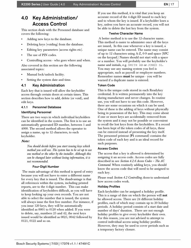
4.1.1 Personnel Database
Identifying Personnel
There are two ways in which individual keyholderscan be identified in the system. The first is to use anautomatically generated ID number, between 1 and4000. The second method allows the operator toassign a name, up to 12 characters, to eachkeyholder.
Note:You should decide before you start issuing keys whichmethod you will use. The system has to be set up to useone method or the other by the installer. Although thiscan be changed later without losing information, it isnot recommended.
Four-Digit Number
The main advantage of this method is speed of entrybecause you will not have to enter a different namefor every key that is issued. The disadvantage is thatall references within the system, including printedreports, are to the 4-digit number. This can makeidentification of keyholders difficult, as you will haveto keep looking up your own records. You are notable to select the number that is issued, the systemwill always issue the first free number. For instance, ifyou issue 120 keys, they will be automaticallyidentified as 0001 to 0120 when added. If you wereto delete, say, numbers 25 and 42, the next keysissued would be identified as 0025, 0042 followed by0121, 0122 and so on.
If you use this method, it is vital that you keep anaccurate record of the 4-digit ID issued to each keyand to whom the key is issued. If a keyholder loses akey, unless you have an accurate record, you will notbe able to delete the lost key from the system.
Twelve Character Name
A better method is to use the 12-character name.This method is easier to administer once all the keysare issued, In this case whenever a key is issued, aunique name can be entered. The name may consistof up to 12 characters using A-Z, 0-9 and space (SPCon the keypad.) Names should not start with a spaceor a number. You will probably use the keyholder'sname and initials, e.g. SMITH AB or JONES SL.You may use any naming system you feel isappropriate, such as payroll or employee numbers.Remember names must be unique - you will bewarned if a duplicate name is entered.
Token Code
This is the unique code stored in each Readykeycredential. It is written permanently into the keyduring manufacture and never changes. In routineuse, you will not have to use this code. However,there are some occasions on which it can be used.One of these is the adding of keys without physicallybeing in possession of the key. This may come aboutif one or more keys are accidentally removed fromthe system and it may not be possible or convenientto recall the lost keys from the keyholders. If a recordhas been kept of the token codes of all keys, thesecan be entered instead of presenting the key itself.The personnel printout (P1 command) contains thetoken code of each key and is an ideal record forsuch purposes.
Access Codes
The access that a key is allowed is determined byassigning it an access code. Access codes are fullydescribed in see Section 4.2.6 Access Codes – The ACCommand. When routinely adding keys, you shouldknow the access code that will need to be assigned toeach key.
Please read Section 4.2 Controlling Access to understandhow access codes work.
Holiday Profiles
Each keyholder can be assigned a holiday profile.This is a range of date on which the person will notbe allowed access. There are 24 different holidayprofiles, each of which may contain up to 20 holidayperiods. A holiday period consists of a start date andnumber of days’ duration. There are not enoughholiday profiles to give every keyholder their own.For this reason, you are not advised to attempt tocontrol individual access using holiday profiles.However, they may be used to cover periods such asa temporary factory closure.
K2200 Series | User Guide | 4.0 Key Administration/ Access Control EN | 18
Bosch Security Systems | 7/03 | 17376 v1.1 / 47491C
Holiday periods and profiles are defined using theHR and HP commands (see Section 4.2.7 Holidays –The HR and HP Commands) and are applied to a keyusing the Edit (E) command (see Section 4.1.4 EditingKeys – The E Command).
4.1.2 Adding Keys – The A Command
This procedure describes how to add a key to adatabase. Before you start you should have or knowthe following:
• An editor key with an editor level that allowsadding of keys
• One or more keys to add
• The names of each keyholder (not required ifusing 4-digit identification)
• The access code to be assigned to eachkeyholder
To Add a Key:1. Present an editor key to the faceplate reader.2. Enter the password and press [ENT], if required.3. You will now see the CMD prompt.4. Type [A] and press [ENT].
CMD A_
5. The next available unused ID number will nowappear along with a prompt to enter the accesscode.
ID 27 AC 0
Type the access code (0 to 128) and press [ENT].Press [NXT] to go on to the next prompt.
6. Enter an identification name for this key whichmay be a name, a payroll number or aflat/residence name.
WHO _
Note:This prompt will only appear when you are using 12-character IDs.
You may use any of the characters on thekeyboard (A-Z, 0-9, SPC). Do not start a namewith a space or a numberIf you enter an ID that is already being used, themessage DUPLICATE NAME will appear forabout 2 seconds before returning to the WHOprompt.
DUPLICATE NAME
Press [NXT] to go on to the next prompt.7. At this prompt
KEY 00000000
you can either:
- Present the key to be added to thefaceplate reader. If the key is valid, theaddition of this key is complete and youwill move directly to a prompt for the
next key. There is no need to press[ENT] or [NXT].
- Type the 8-character key code.
If for some reason you are not inpossession of the key, provided youknow its 8-character code, you can enterit here. Use only the characters A-F and0-9.
When complete press [ENT].
If the key is valid, the addition of thiskey is complete and you will movedirectly to a prompt for the next key.There is no need to press [NXT].
If, using either of these two methods,you enter a key that is already storedyou will get a message
REPEATED KEY
for about 2 seconds before returning tothe KEY prompt.
8. If you have no more keys to add, press [ESC] toreturn to the CMD prompt.If not, you can now continue adding keys
ID 28 AC 0
Note:The access code remains the same as the previous keyyou entered. If adding a large number of keys, bygrouping them by access code you will speed up entry aswell as reducing the risk of error.
Once a key has been added, it will be recognized byall the readers in the system. However, this will notbe the case if:
Slave door controllers are disconnected or notcommunicating with the master.
A download is in progress to a slave door controller,in which case the new information will not reach theslave until completion of the download.
4.1.3 Deleting (Voiding) Keys – The V Command
Removing keys from the system is a very simpleprocess. Several options are available for selectingthe key to be removed. They are:
• When prompted, present the key to the faceplatereader.
• Enter the 4-digit ID number.
• Enter the 12-character ID, if used.
• Use the up and down arrow keys to search forthe key in the database.
K2200 Series | User Guide | 4.0 Key Administration/ Access Control EN | 19
Bosch Security Systems | 7/03 | 17376 v1.1 / 47491C
•
010101010101
Instead of voiding a key from the system,consider changing its access code to 0(zero). By doing this you will prevent useof the key (any attempt will result in a NoAccess: Locked Out transaction beinggenerated) but you will also have a recordof a 'lost' key being used unsuccessfully
To Void a Key:1. Present an editor key to the faceplate reader.2. Enter the password and press [ENT], if required.3. You will now see the CMD prompt.4. Type [V] and press [ENT].
CMD V_
5. At the ID Prompt,
ID _
you can select the key to be deleted using one ofthese methods:
- If you are in possession of the key itself,present the key to the faceplate reader.
If the key is not in the database, youwill get a message for about 2seconds
NOT IN DATABASE
before returning to the ID prompt.
- Type the 4-digit ID of the key and press[ENT]. Any number between 1 and 4000will be accepted.
- If you are using 12-character IDs, youcan type the ID and press [ENT]. Youmust type the name exactly as it wasoriginally entered. If no match is found,you will get a message
UNKNOWN NAME
for about 2 seconds before returningto the ID prompt.
6. Whatever method you use to find a key, you willbe presented with the ID number and accesscode.
ID 27 AC 7
7. At this point, you can use the up and downarrow keys to move through the database to findthe key you want to delete. You can also pressthe FastFind (*) button to return to the IDprompt.
WHO SMITH AB
8. Once you have selected the key you want todelete, press [ENT].
9. At the CONFIRM VOID prompt,
CONFIRM VOID
press [Y] to confirm and you will be returned tothe CMD prompt. Any other key will return youto the CMD prompt without voiding the key.
When a key has been voided, it will be rejected byall the readers on the system and aNo Access: Unknown ID transaction will beproduced. This will not be the case if:
• Slave door controllers are disconnected or notcommunicating with the master.
• A download is in progress to a slave doorcontroller, in which case the new informationwill not reach the slave until completion of thedownload.
4.1.4 Editing Keys – The E Command
You can change the access code of a key as well asthe 12-character name (if used) at any time. You canalso assign a holiday profile to a keyholder. Theaccess code and holiday profile must already bedefined (see Section 4.2.6 Access Codes – The ACCommand and Section 4.2.7 Holidays – The HR and HPCommands).1. Present an editor key to the faceplate reader.2. Enter the password and press [ENT], if required.3. You will now see the CMD prompt.4. Type [E] and press [ENT].
CMD E_
5. At the ID prompt,
ID _
you can either use the up and down arrow keysto select a key, or press the FastFind (*) button.
- If you are in possession of the key itself,present the key to the faceplate reader.
If the key is not in the database, youwill get a message for about 2seconds
NOT IN DATABASE
before returning to the ID prompt.
- Type the 4-digit ID of the key and press[ENT]. Any number between 1 and 4000will be accepted.
- If you are using 12-character IDs, youcan type the ID and press [ENT]. Youmust type the name exactly as it wasoriginally entered. If no match is found,you will get a message
UNKNOWN NAME
for about 2 seconds before returningto the ID prompt.
6. Whatever method you use to find a key, you willbe presented with the ID number and accesscode.
ID 27 AC 7
K2200 Series | User Guide | 4.0 Key Administration/ Access Control EN | 20
Bosch Security Systems | 7/03 | 17376 v1.1 / 47491C
7. At this point, you can use the up and downarrow keys to move through the database to findthe key you want to delete. You can also pressthe FastFind (*) button to return to the IDprompt.
WHO SMITH AB
8. Once you have selected the key you want to edit,press [ENT].
9. You can change the access code by typing thenew value and pressing [ENT].
ID 27 AC 7
Press [NXT] to go to the next field.10. If using the 12-character ID only, you can enter a
new name. Either type over the existing name orpress [CLR] to clear the field before typing a newname.
WHO SMITH AB
Press [ENT] when you have finished.Press [NXT] to go to the next field.
11. You can enter a holiday profile. Enter a valuebetween 0 and 24 and press ENT.
ID 27 HOLS 0
12. Either press [ESC] to return to the CMD prompt,or use the up and down arrow keys, or FastFind(*) button to search for another key to edit.
When a key has been edited, the changes to accesscode and/or holiday profiles will be observed by allthe readers in the system. This will not be the case if:
• Slave door controllers are disconnected or notcommunicating with the master.
• A download is in progress to a slave doorcontroller, in which case the new informationwill not reach the slave until completion of thedownload.
4.1.5 PIN Codes – The N Command
You may have a special type of Readykey reader onyour system that requires a Personal IdentificationNumber (PIN) to be entered in addition to a keybeing presented. Readykey PIN readers work bycalculating a 4-digit (0000-9999) number from theunique token code embedded in the Readykey key.The keyholder must then enter this PIN codecorrectly before the key will be allowed access by thedoor controller.
An additional feature of the door controllers is thatthey allow a time profile (see Section 4.2.5 TimeProfiles) to control when a reader requires a PIN withthe key or just the key:
• When the time profile is active, the PIN readeroperates like a conventional key reader,requiring no PIN.
• When the time profile is inactive, a key plus thePIN is required to gain access.
This feature must be set using the Doors (D)command, although the time profile is set using theTime Profile (T) and Time Periods (PR) commands
PIN Reader Duress
Another feature of the PIN reader is the ability togenerate a duress alarm. If a keyholder is beingforced to open a door, by adding one to their PIN,the door will open as normal. However, a duressalarm will be reported at the master controller.
Example
If a keyholder has a PIN of 1234 and they enter 1235(PIN plus 1), the door will open as normal but aduress alarm will be generated. You should add oneto the code numerically, e.g. a PIN of 1239 gives1240 as the duress code.
How to Find a Key’s PIN
N Command
To find out the PIN of any Readykey key (it does nothave to be in the database):1. Present an editor key to the faceplate reader.2. Enter the password and press [ENT], if required.
Note:The editor key must have an editor level that allows theviewing of PIN codes.
3. You will now see the CMD prompt.4. Type [N] and press [ENT].
CMD N_
5. Present a key to the faceplate reader.
* PRESENT KEY *
6. The 4-digit PIN will be displayed for about 2seconds.
PIN NO IS 1234
7. Either present other keys to determine their PINcodes, or press [ESC] to return to the CMDprompt.
4.2 Controlling AccessThis section describes how you control the access ofindividual keyholders. This is achieved by assigningeach keyholder an access code. This code is createdby combining access levels (where a person hasaccess) and time profiles (when a person hasaccess).
An additional feature allows you to apply a holidayprofile to a keyholder. This is a range of datesduring which they will be denied access at times theiraccess code would normally allow.
K2200 Series | User Guide | 4.0 Key Administration/ Access Control EN | 21
Bosch Security Systems | 7/03 | 17376 v1.1 / 47491C
In order to administer the systemefficiently, it is essential that you maintaincareful records of access codes, accesslevels, time profiles and time periods. Ifyou do, maintaining the system will bemuch easier and you will be less likely tomake mistakes.
Time profiles, which can be used to control otherfunctions in the system as well as keyholder access,are described in detail in next section.
4.2.1 Access Code Overview
An access code determines through which doors andat what times a key is allowed access.
Each access code has two sets of doors (access levels)both of which may have a time profile attached.
Example
An access code may be set up that allows keyholdersthrough certain doors 24 hours a day, but into otherareas only during normal working hours, say 9:00amto 5:00pm, Monday to Friday.
In this case, you will create an access level consistingof all the doors with no time restriction, and anotheraccess level containing the doors where access isrestricted to working hours. A time profile will thenbe needed covering the time restriction, in thisexample 9:00 to 5:00, Monday to Friday.
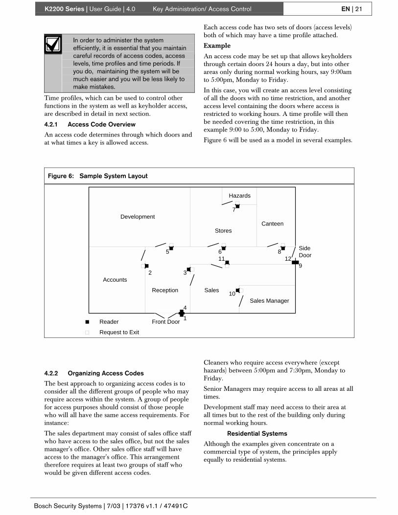
Figure 6 will be used as a model in several examples.
Figure 6: Sample System Layout
SalesReception
Sales Manager
Accounts
Stores
Hazards
CanteenDevelopment
Reader
Request to Exit
Front Door
SideDoor
1
2 3
5 6 8
911 12
10
4
7
4.2.2 Organizing Access Codes
The best approach to organizing access codes is toconsider all the different groups of people who mayrequire access within the system. A group of peoplefor access purposes should consist of those peoplewho will all have the same access requirements. Forinstance:
The sales department may consist of sales office staffwho have access to the sales office, but not the salesmanager's office. Other sales office staff will haveaccess to the manager's office. This arrangementtherefore requires at least two groups of staff whowould be given different access codes.
Cleaners who require access everywhere (excepthazards) between 5:00pm and 7:30pm, Monday toFriday.
Senior Managers may require access to all areas at alltimes.
Development staff may need access to their area atall times but to the rest of the building only duringnormal working hours.
Residential Systems
Although the examples given concentrate on acommercial type of system, the principles applyequally to residential systems.

K2200 Series | User Guide | 4.0 Key Administration/ Access Control EN | 22
Bosch Security Systems | 7/03 | 17376 v1.1 / 47491C
Generally speaking, residential systems have lesscomplex access requirements. Residents will usuallybe given an access code that allows them access totheir dwelling only, with no time restriction. Separateaccess codes will therefore be created for each blockor landing, depending on where the readers arelocated.
Other non-residents will probably need access, forinstance, deliveries, cleaners, maintenance etc. either24 hours a day, or at restricted times.
4.2.3 How to Create Access Codes
To create access codes for a group of people youshould follow these steps:
1. Decide which doors the group will be allowedthrough.
2. Decide at what times they will have accessthrough these doors. If necessary you can havetwo lists of doors (access levels) in one accesscode, one allowing access on one Time Profile,the second allowing access at a different TimeProfile.
3. Check to see if you already have appropriateaccess levels and time profiles already set up. Ifnot, create new ones (The A, PR and Tcommands).
4.2.4 Access Levels – The AL Command
Very simply, an access level is a list of doors. Thereis a maximum of 16 doors that may be controlled bythe Readykey K2200 system. You use an access levelto define which of those 16 doors different people, orgroups of people, will be allowed to use.
There are 128 possible access levels that you can setup.
Note:In a new system, you should find that access level 1 hasbeen automatically set to all doors. That is, an accesscode which contains access level 1 will allow thekeyholder through all the doors in the system.
Before you attempt to use this command, you should beaware of the numbers assigned to each door. In theexample above for instance, door 1 is the front door,door 3 is the sales office (from reception), door 11 is thesales office from the corridor, door 4 and door 12 areexit doors.
The table to the right shows which doors are associatedwith which door controller.
Table 10: Door to Door Controller Association
DoorController
Door Numbers
Master 1 2 3* 4*Slave 2* 5 6 7* 8*Slave 3* 9 10 11* 12*Slave 4* 13 14 15* 16*
* Not available on Readykey K1200
In order to show all the settings for 16 doors in eachaccess level, the display has to be split into twohalves. You should use the [NXT] and [-] keys tomove between the two displays
To create or alter an access level1. Present an editor key to the faceplate reader.2. Enter the password and press [ENT], if required.3. You will now see the CMD prompt.4. Type [A][L] and press [ENT].
CMD AL_
5. What you see displayed are the first 8 doors ofaccess level 1. The 1 in the center of the displayindicates this is the first half of the display (doors1-8).
L 1 1 12345678
Press [NXT] to see the second set of 8 doors.6. The 2 indicates this is the second set of 8 doors
(9-16). In this example, access level 1 allowsaccess through all the possible doors in thesystem.
L 1 2 12345678
Use the up and down arrow keys to select theaccess level you want to change.
7. Once you have selected the access level youwant to change, you select or deselect doors bytyping the numbers 1-8. If a door is selected, itsnumber will appear on the list; if it is deselected,a dash (-) will replace the number.
L 17 1 12----78
Press [ENT] to save any changes you have made.Press [NXT] to see the second set of 8 doors (9-16). Press [ENT] again to save any changes youhave made to the second set.
L 17 2 ----56--
The example shows an access level (number 17)that allows keyholders through doors 1, 2, 7, 8,13 and 14
8. Select another access level to change or press[ESC] to return to the CMD prompt.

K2200 Series | User Guide | 4.0 Key Administration/ Access Control EN | 23
Bosch Security Systems | 7/03 | 17376 v1.1 / 47491C
4.2.5 Time Profiles
Note:Time profiles are used to control several features of thesystem as well as controlling keyholder access. They arefully described in Section 4.3 Time Profiles.
There are up to 128 time profiles available within thesystem. It is recommended that you set up individualtime profiles specifically for controlling keyholderaccess. For instance, you may have a time profile thatautomatically unlocks the front door between 9:00amand 5:00pm, Monday to Friday, for public access.You may be tempted to use the same time profilewhen limiting access of keyholders to an area for thesame time period. However, if in the future youdecide to alter the keyholder access times, you wouldalso alter the door opening times.
Note:If you have no intention of placing time restrictions onkeyholder access, there is no need to use time profiles atall. If no time profiles are used, keyholders will beallowed 24 hour, 7 day access through doors that theiraccess code allows
4.2.6 Access Codes – The AC Command
Access codes are used to combine where a personhas access (access levels) and when (time profiles).
Each code has a primary access level and time profileplus a secondary access level and time profile. (Set inthe AL command). This allows access to be given toone set of doors at one time, and another set of doorsat another time. If no time profiles are assigned, thekeyholders will have access at all times.
Table 11: Access Level Examples
Primary Access Level: 1 Access Level 1: 12345678 12345678
Primary Time Profile: 0
Secondary Access Level: 0
The simplest example allowskeyholders with this code accesseverywhere at all times. In asystem that has just beeninitialized, this is the case foraccess code 1.
Secondary Time Profile: 0
Primary Access Level: 7 Access Level 7: 1--4---- 1--4----
Primary Time Profile: 0
Secondary Access Level: 8 Access Level 8: -23----8 --3-----
The next example allowskeyholders through the front andside doors at all times, but onlyinto the sales office, accountsand the canteen between8:30am and 6:00pm Mon-Fri,8:30am and 1:00pm Sat.
Secondary Time Profile: 3 Time Profile 3: 08:30-18:00 MTWTF—H08:30-13:00 -----S-H
Primary Access Level: 9 Access Level 9: 123456-8 1234----
Primary Time Profile: 5 Time Profile 5: 07:00-09:30 MTWTF--H
Secondary Access Level: 0
This example may be used toallow cleaners access early in themorning.
Secondary Time Profile: 0Primary Access Level: 11 Access Level 11: 1--4-678 1--4----
Primary Time Profile: 0Secondary Access Level: 12 Access Level 12: 12345678 1-34----
The Stores Manager needsaccess to the building andStores, but is only allowed intoother areas during office hours. Secondary Time Profile: 3 Time Profile 3 08:30-18:00 MTWTF—H
08:30-13:00 -----S-H
Note:Quite often access levels or time profiles will overlap.For instance, the primary access level may not allowaccess, but the secondary access level will. In these cases,if either access level allows the keyholder access, thedoor will open.
Using the AC Command
To set access codes use the AC command. At thispoint, you should know what access levels are set andwhat time profiles, if any, you are going to use.1. Present an editor key to the faceplate reader.2. Enter the password and press [ENT], if required.3. You will now see the CMD prompt.4. Type [A][C] and press [ENT].
CMD AC_
5. What you see displayed is the Primary accesslevel for access code 1.
AC 1 PAL 1
Use the up and down arrow keys or FastFind (*)to select the access code you want to change.
6. Primary Access Level- Once you have selectedthe access code you want to use, type theprimary access level (0-128) and press [ENT].
AC 3 PTP 0
Press [NXT] to go to the next field.7. Primary Time Profile - Enter the time profile you
want to apply to the primary access level. If youwant no time restriction, enter 0. Press [ENT].

K2200 Series | User Guide | 4.0 Key Administration/ Access Control EN | 24
Bosch Security Systems | 7/03 | 17376 v1.1 / 47491C
AC 3 PTP 0
Press [NXT] to go to the next field.8. Secondary Access Level- Type the secondary
access level (0-128) and press [ENT].
AC 3 PTP 0
Press [NXT] to go to the next field.9. Secondary Time Profile - Enter the time profile
you want to apply to the secondary access level.If you want no time restriction, enter 0. Press[ENT].
AC 3 PTP 0
Press [NXT] to go to the next field.
4.2.7 Holidays – The HR and HP Commands
The door controllers allow the setting up of 24different holiday profiles. Each holiday profileconsists of up to 20 holiday periods, a holiday periodbeing a start date and duration. Up to 254 holidayperiods can be defined on a standalone system.
Once a holiday period been defined, it can beapplied to any keyholder using the E command (seeSection 4.1.4 Editing Keys – The E Command). When aholiday profile is active, any keyholder assigned theholiday profile will not gain access and aNo Access: Holiday event will be recorded.
System Holidays
Holiday profile 1 is a special case. It contains all theholiday periods that can be used to override timeprofiles. This means that, for instance a door thatautomatically opens during office hours, Monday toFriday, will not open on holidays that may fallduring the week, such as public holidays, ChristmasDay. Likewise, a person allowed into a buildingduring the week can be prevented from gainingaccess on such days.
For this reason, you should refrain from usingholiday profile 1 for keyholder use and reserve it forsystem holiday use only.
One technique for maintaining system holidays is toassign holiday periods 1 to 20 to holiday profile 1.Assign known dates and durations to those holidayperiods. Once a year, you should enter all the knownholidays for the following year or so. Using thismethod you only need to replace holiday periodsthat have passed with future holidays.
Holiday Periods – The HR Command
There are 24 possible holiday periods. Each consistsof a start date and duration. The duration includesthe start date itself. For instance, if you want aholiday period to cover Christmas Eve andChristmas Day, you would enter a start date of12/24/00 and a duration of 2 days. For example, ifyou want just a single day, enter the start date12/25/00 and duration 1 day.1. Present an editor key to the faceplate reader.
2. Enter the password and press [ENT], if required.3. You will now see the CMD prompt.4. Type [H][R] and press [ENT].
CMD HR_
5. At this display,
ST 1 00-00-00
Use the up and down arrow keys or FastFind (*)to select the holiday period you want to change
6. Holiday Period Start Date - Once you haveselected the holiday period you want to use, typethe start date. The cursor will 'jump' over theseparator characters as you enter the date.
ST 5 00-00-00
Press [ENT].Press [NXT] to go to the next field.
7. Holiday Period Duration - Enter the numbers ofdays the period will last.
DURATION 1 0
Press [ENT].Press [ESC] to return to the CMD prompt.
Holiday Profiles – The HP Command
Up to 20 holiday periods can be assigned to aholiday profile. A total of 24 holiday profiles areavailable. Holiday profile1 has a special purpose, seeSystem Holidays.
Using the HP Command1. Present an editor key to the faceplate reader.2. Enter the password and press [ENT], if required.3. You will now see the CMD prompt.4. Type [H][P] and press [ENT].
CMD HP_
5. Use the up and down arrow keys or FastFind (*)to select the holiday profile you want to change.
HOL 1 ON/OFF N
6. Holiday Profile Active - Type [Y] to make theprofile active, [N] to deactivate it. If youdeactivate an active profile, any restrictions thatwere in force will be removed.
HOL 1 ON/OFF N
Press [ENT]Press [NXT] to go to the next field.
7. Holiday Period - Enter the holiday period andpress [ENT].There are 20 fields that you can enter here, press[NXT] to go to the next period.
HOL 1 ON/OFF N
Press [ESC] to return to the CMD prompt.
4.3 Time ProfilesTime profiles are a powerful tool that have severalfunctions within the access control system:
K2200 Series | User Guide | 4.0 Key Administration/ Access Control EN | 25
Bosch Security Systems | 7/03 | 17376 v1.1 / 47491C
• Restricting the access of personnel as part oftheir access code.
• Automatically locking and unlocking doors.
• Automatically enabling an additional alarm point(alarm module).
• Automatically switching a relay on the doorcontroller or an alarm module relay.
• Switching a PIN reader between key plus PINand key only.
Examples1. A public access door through which anybody
can pass between 9:00am and 5:00pm, Mondayto Friday, but outside these hours a key isrequired.
2. Some staff are only allowed access between8:30am and 5:30pm, Monday to Friday; 8:30amto 12:00pm Saturday.
3. Cleaners are allowed access only between7:00am and 9:00am Monday to Saturday.
4. Shift workers can gain access between 8:00pmand 6:00am Monday to Friday.
Note:If you are never going to use time controls of any type,there is no need to set up any time profiles at all, justuse a time profile of 0 where required.
4.3.1 How Time Profiles Work
There are 128 different time profiles. Each timeprofile consists of up to three time periods. A timeperiod consists of a start time, an end time and thedays of the week to which it applies. For instance,example 1 requires just one time period, 9:00am(start time) to 5:00pm (end time), Monday to Friday(days of the week); example 2 requires two timeperiods, 8:30am to 5:30pm Monday to Friday plus8:30am to 12:00pm Saturday only.
You can define up to 32 different time periods, andup to three of these time periods can be used tocreate one of 128 time profiles. A time period mayappear in more than one time profile.
The time profile is active from thebeginning of the first minute of each timeperiod until the end of the final minute ofeach time period on the days of the weekto which it applies. In addition, if theholiday option is set for a time profile, thetime profile will not be active on any dayscontained in holiday profile 1.
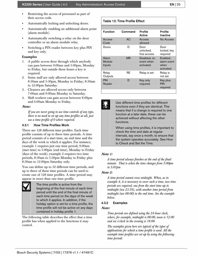
The following table describes the effect that a timeprofile has when applied to the functions it maycontrol.
Table 12: Time Profile Effect
Function Command ProfileActive
ProfileInactive
AccessCode
AC Accessallowed
No Access
Doors D Doorunlocked,free access.
Doorlocked, keyrequired
AlarmModuleInputs
MR Disabled, noevent whenactivated.
Enabled,alarm eventwhenactivated.
RelayOutputs
RE Relay is set Relay isnot set
PINReader
D Key onlyrequired.
Key plusPINrequired
010101010101
Use different time profiles for differentfunctions even if they are identical. Thismeans that if a change is required to onefunction at a later date, these can beachieved without affecting the otherfunctions.
When using time profiles, it is important tocheck the time and date at regularintervals, say once a month, to ensure thatthe system operates accurately. See Howto Check and Set the Time.
Note 1:A time period always finishes at the end of the finalminute. That is when the time changes from 5:00pmto 5:01pm
Note 2:A time period cannot cross midnight. When, as inexample 4, it is necessary to cover such a time, two timeperiods are required, one from the start time up tomidnight (use 23:59), with another time period frommidnight (use 00:00) to the end time. See the examplebelow.
4.3.2 Examples
Note:Time periods are defined using the 24-hour clock,where, for example, midnight is 00:00, noon is 12:00and six o'clock in the evening is 18:00.
The examples given here are typical of the types ofapplications for which a time profile is used. All theexample time profiles are set up by using the followingtime periods

K2200 Series | User Guide | 4.0 Key Administration/ Access Control EN | 26
Bosch Security Systems | 7/03 | 17376 v1.1 / 47491C
Table 13: Time Period Examples
Start Time End Time Days1 08:45 17:30 MTWTF--H
2 08:45 13:30 -----S-H
3 18:00 23:59 MTWTF--H
4 00:00 06:00 -TWTFS--
5 00:00 00:00 --------
6 00:00 00:00 --------
7 09:00 17:00 MTWTF--H
8 00:00 23:59 -----SS-
1. A group of people requires access to an areaduring working hours only. In this case workinghours are 9:00am to 5:00pm Monday to Fridayand 9:00am to 1:00pm Saturday. They will notbe allowed access on public holidays if these fallon weekdays. Notice that some extra time isallowed at the start and end of the period toallow people to arrive early and leave late.
Period1: 1 08:45 17:30 MTWTF--H
2: 2 08:45 13:30 -----S-H
3: 02. A public entrance door needs to be unlocked
during office hours, but not on public holidays.Unlike the example 1, there is no 'spare' time atthe start and end of the period.
Period1: 7 09:00 12:00 MTWTF--H
2: 03: 0
3. Shift workers need access to an area between6:00pm and 6:00am Monday to Friday.
Period1: 3 18:00 23:59 MTWTF---
2: 4 00:00 06:00 -TWTFS--
3: 0
Note:In this case, because they work over midnight, they needaccess on the following day, i.e. they arrive for work onFriday evening but leave on Saturday morning. Youneed to use caution when restricting access on publicholidays in these cases. A 'normal' working day maystart or finish on a holiday.
4.3.3 The PR Command1. Present an editor key to the faceplate reader.2. Enter the password and press [ENT], if required.3. You will now see the CMD prompt.4. Type [P][R] and press [ENT].
CMD PR_
5. Use the up and down arrow keys or FastFind (*)to select the time period you want to change.
P1 START 00-00
6. Period Start - Using the 24-hour clock, enter thestart time of the period and press [ENT].
P1 START 00-00
Press [NXT] to go to the next field.7. Days of the Week - This is an option field. To
make the time period active on a particular dayof the week, type a number as follows:1 Mon, 2 Tue, 3 Wed, 4 Thu, 5 Fri, 6 Sat, 7 Sun,8 Hol
P1 --------
When you press a number, the initial letter of theday will appear. To deselect a day press itsnumber again, a dash will appear at that day.The holiday option 8 indicates that this timeperiod will not be active on a system holiday.Press [ESC] to return to the CMD prompt.
4.3.4 Creating a Time Profile – The T Command
Before creating a time profile, ensure that the timeperiods you require have already been set, see Section4.3.3 The PR Command.
Using the T Command1. Present an editor key to the faceplate reader.2. Enter the password and press [ENT], if required.3. You will now see the CMD prompt.4. Type [T] and press [ENT].
CMD T_
5. Use the up and down arrow keys or FastFind (*)to select the time profile you want to change.
TP 1 ON Y
6. Time Profile Status - See the description in seeSection 4.3.1 How Time Profiles Work, tounderstand the significance of this setting.
TP 1 ON N
Type [Y] to switch the time profile ON, Type [N]to switch the time profile OFF.Press [ENT].Press [NXT] to go to the next field.
7. First Time Period - Enter the first time periodnumber (0-32). Enter [0] if you do not need thistime period.Press [ENT].
TP 1 PER 1 0
Press [NXT] to go to the next field.8. Second Time Period - Enter the second time
period number (0-32). Enter [0] if you do notneed this time period.Press [ENT].
TP 1 PER 2 0
Press [NXT] to go to the next field.

K2200 Series | User Guide | 4.0 Key Administration/ Access Control EN | 27
Bosch Security Systems | 7/03 | 17376 v1.1 / 47491C
9. Third Time Period - Enter the third time periodnumber (0-32). Enter [0] if you do not need thistime period.Press [ENT].
TP 1 PER 3 0
Press [ESC] to return to the CMD prompt.
4.4 System Administration4.4.1 Changing the Date and Time – The C
Command
Once set at installation, the door controller willmaintain its time using a battery backed real-timeclock. You should check the clock regularly to ensureaccuracy. This is particularly important if you usetime profiles for controlling system functions andaccess.
Summertime (or Daylight Saving Time)
You will need to adjust the clock twice a year whenthe clocks go back (Autumn) and forward (Spring).
How to Check and Set the Time
To check the date and time use the C Command:1. Present an editor key to the faceplate reader.2. Enter the password and press [ENT], if required.3. You will now see the CMD prompt.4. Type [C] and press [ENT].
CMD C_
5. Type the new date over the existing date, or usethe left and right arrow keys to move the cursorto the figures you want to change.
DATE 10-11-93
If you press [CLR], you should re-enter the timewith a space between the hours and minutes.
Note:The cursor moves over the separator character (-) to thenext digit.
Press [ENT] when complete.If the date you enter is invalid, it will be adjustedto the nearest valid date.Press [NXT] to go to the next field.
6. Type MON, TUE, WED, THU, FRI, SAT or SUN andpress [ENT].
ENTER DAY TUE
If you do not type one of the above 3-characternames, the display will default to MON.Press [NXT] to go to the next field.
7. Type the new time over the existing time, or usethe left and right arrow keys to move the cursorto the figures you want to change.
ENTER TIME 16-01
Note:The cursor moves over the separator character (-) to thenext digit.
If you press [CLR], you should re-enter the timewith a space between the hours and minutes.Press [ENT] when complete.If the time you enter is invalid, it will be adjustedto the nearest valid time.
8. Press [ESC] to return to the CMD prompt.
4.4.2 Manual Lock/Unlock – The L Command
It is possible to manually lock and unlock a doorfrom the master controller. It may be necessary to dothis, for instance when a door needs to be kept openwhile contractors are working in an area orequipment is being moved around. Also, a doornormally unlocked on a time profile may need to belocked while a receptionist or guard is not available.
Manual lock will lock the door. Keys will then berequired to gain access. If no further action is taken,the door will still unlock at its next automaticopening time.
If the door is manually unlocked, it will lock at itsnext automatic closing time.
Note:The door will remain unlocked unless another action isperformed. (Automatic lock or manual lock).
Using the L Command1. Present an editor key to the faceplate reader.2. Enter the password and press [ENT], if required.3. You will now see the CMD prompt.4. Type [L] and press [ENT].
CMD L_
5. You now see displayed the state of door 1. N(Normal) means that no manual override is inoperation - the door IS locked.
DOOR 1 STATE N
To select the door you want locked or unlocked,you can either use the up and down arrow keysto select an access level, or press the FastFind (*).If you use FastFind type the door number yourequire and press ENT.
FIND _
6. Once you have selected the door you require:
DOOR 10 STATE N
Type [L] and press [ENT] to lock the door.Type [U] and press [ENT] to unlock the door.
7. Press [ESC] to return to the CMD prompt.

K2200 Series | User Guide | 5.0 Displays, Alarms, and Printing EN | 28
Bosch Security Systems | 7/03 | 17376 v1.1 / 47491C
5.0 Displays, Alarms, andPrinting
Each controller with a faceplate displays informationabout the status of doors and communications. Themaster controller will, in addition, show informationsuch as alarms reports and communication errorsbetween the master and any slave controllers.
This section describes the various displays and alsocovers the printing options which are available. Thesection is split into the following sections:
• Normal Operation. This describes what toexpect on the display when the system isoperating normally.
• Alarms. This describes the how alarms arehandled by the controller and includesAccepting Alarms, Uncleared Alarms, and soon
• Communication Errors. This describes thevarious communication errors that can occur.
• Other System Messages. This provides adescription of other displays that may appear onthe front panel.
• Printing. This describes the printing optionsavailable and includes details of the variousreports that can be printed.
5.1 Normal OperationThe following displays show what to expect when thesystem is operating normally, with no errors oralarms.
5.1.1 Master Controller
The display will be blank when no doors are openand everything is operating normally.
5.1.2 Slave Controller
A number, the address of the door controller (2, 3 or4), will flash at the right of the display. This indicatesthat the slave controller is being 'polled' by themaster.
2
5.1.3 Master and Slave
This display indicates one or more doors beingunlocked on the door controller. This may be due to:
• A valid key being presented to a reader.
• A Request to Exit button being pressed.
• The door being automatically open due to a timeprofile.
• The door being opened by a Manual Unlockcommand.
Examples
DOORS OPEN 1234
DOORS OPEN 1 4
5.2 AlarmsThe door controller is capable of reporting severaltypes of alarm condition. These are described belowalong with the screen display and printer transaction.
All alarm conditions, wherever they occur, arereported at the master controller. If communicationsare broken between a slave and the master, the slaveitself will report the alarm. When communicationsare restored, the alarm will be transferred to themaster - even if the alarm was accepted at theslave.
When a printer is attached, you will have a record ofthe alarm along with its time, date and location.When the alarm condition clears, another report willbe generated with the date and time of the event.
5.2.1 Accepted Alarms
All alarm conditions must be accepted at the master.This is done by presenting an editor key to thefaceplate reader. All editor keys will accept alarms.The printer, if attached, will show the date, time andidentity of the editor that accepted the alarm.
5.2.2 Alarm Activations
Below are shown examples of alarm activations. Ineach case, the display shown will appear indicatingthe type of alarm and its location. At the same time apulsing beep will be generated. The display and beepwill continue until the alarm is accepted by an editorkey.
If more than one alarm occurs, the next alarm willappear on the display only once the first is cleared.All alarms however will be printed as they occur.
Unauthorized Access / Anti-Tamper Alarm
A door has opened (may be 2 readers/door) withouta key being presented or a Request to Exit buttonpressed.
Anti-Tamper Alarm A reader cable has been cutor a reader has been removed.
READER 1 ALARM
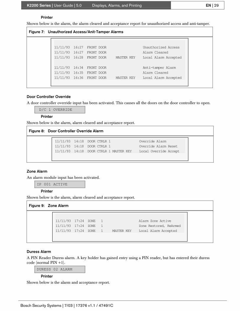
K2200 Series | User Guide | 5.0 Displays, Alarms, and Printing EN | 29
Bosch Security Systems | 7/03 | 17376 v1.1 / 47491C
Printer
Shown below is the alarm, the alarm cleared and acceptance report for unauthorized access and anti-tamper.
Figure 7: Unauthorized Access/Anit-Tamper Alarms
11/11/93 16:27 FRONT DOOR Unauthorized Access
11/11/93 16:27 FRONT DOOR Alarm Cleared
11/11/93 16:28 FRONT DOOR MASTER KEY Local Alarm Accepted
11/11/93 16:34 FRONT DOOR Anti-tamper Alarm
11/11/93 16:35 FRONT DOOR Alarm Cleared
11/11/93 16:36 FRONT DOOR MASTER KEY Local Alarm Accepted
Door Controller Override
A door controller override input has been activated. This causes all the doors on the door controller to open.
D/C 1 OVERRIDE
Printer
Shown below is the alarm, alarm cleared and acceptance report.
Figure 8: Door Controller Override Alarm
11/11/93 14:18 DOOR CTRLR 1 Override Alarm
11/11/93 14:18 DOOR CTRLR 1 Override Alarm Reset
11/11/93 14:18 DOOR CTRLR 1 MASTER KEY Local Override Accept
Zone Alarm
An alarm module input has been activated.
IP 001 ACTIVE
Printer
Shown below is the alarm, alarm cleared and acceptance report.
Figure 9: Zone Alarm
11/11/93 17:24 ZONE 1 Alarm Zone Active
11/11/93 17:24 ZONE 1 Zone Restored, ReArmed
11/11/93 17:24 ZONE 1 MASTER KEY Local Alarm Accepted
Duress Alarm
A PIN Reader Duress alarm. A key holder has gained entry using a PIN reader, but has entered their duresscode (normal PIN +1).
DURESS 02 ALARM
Printer
Shown below is the alarm and acceptance report.

K2200 Series | User Guide | 5.0 Displays, Alarms, and Printing EN | 30
Bosch Security Systems | 7/03 | 17376 v1.1 / 47491C
Figure 10: Duress Alarm
11/11/93 16:17 SALES OFFICE SMITH AB PIN Reader Duress Alarm11/11/93 16:17 SALES OFFICE MASTER KEY Local Duress Accepted
Case Tamper
A door controller cabinet has been opened.
DC 1 TAMPER
Printer
Shown below is the alarm, alarm cleared and acceptance report.
Figure 11: Case Tamper Alarm
11/11/93 17:49 DOOR CTRLR 1 Anti-tamper Alarm
11/11/93 17:50 DOOR CTRLR 1 Alarm Cleared
11/11/93 17:50 DOOR CTRLR 1 MASTER KEY Local Alarm Accepted
Alarm Module Tamper
An alarm module case has been opened.
MODULE 01 ALARM
Printer
Shown below is the alarm, alarm cleared and acceptance report.
Figure 12: Alarm Module Tamper Alarm
11/11/93 14:16 Alarm Module 01 Anti-tamper Alarm
11/11/93 14:16 Alarm Module 01 Alarm Cleared
11/11/93 14:16 Alarm Module MASTER KEY Local Alarm Accepted

K2200 Series | User Guide | 5.0 Displays, Alarms, and Printing EN | 31
Bosch Security Systems | 7/03 | 17376 v1.1 / 47491C
5.2.3 Uncleared Alarms
Once one or more alarms have been accepted, thedoor controller will display the status of anyuncleared alarms. Also shown will be the states ofany Alarm Module inputs.
CHn- d iiiiiiii
Table 14: : Display Key
Variable Description Options
CHn The readerchannelnumber
n = 1-4
= A alarm condition= 0 door left open
d Door state
= C closed= not used= I isolated (manual or
auto)= A active
I AlarmInputs
= N normal
5.2.4 Communication Errors
When a master controller has one or more slavecontrollers attached, there is always the possibility ofa break in communications. If this occurs, the masterdoor controller will report this on its display.
If there is more than one error, that is more than oneslave door controller is not communicating, eachmessage will be displayed in turn for about 5seconds.
Comms Error 1
A comms error 1 indicates that the master doorcontroller is trying to communicate with a slave but isgetting no response.
D/C 2 ERROR-1
This may be because:
• The slave is not powered.
• The address of the slave is not set correctly.
• The cable between the master and slave isbroken or disconnected.
Comms Error 2
D/C 2 ERROR-2
These errors indicate corrupt replies from a slavedoor controller are corrupt. This may indicate poorwiring, or strong interference.
Comms Error 3
D/C 2 ERROR-3
These errors indicate corrupt replies from a slavedoor controller are corrupt. This may indicate poorwiring, or strong interference.
5.3 Other System MessagesOther displays that you may see on the faceplatedisplay are:
5.3.1 Update Progress
If changes are made that affect a slave doorcontroller, these will automatically be sent. Howeverif a large number of changes are made or the slave isnot connected, the changes will be stored. Thisdisplay indicates how many updates are currentlystored for each door controller. Once the doorcontroller communications are restored you shouldsee the number decrease to 0.
D/C 2 UPDATE-01
5.3.2 Download Progress
You will see this message on the screen when youleave the editor after initiating a download to all theslave door controllers. It indicates the progress of thedownload, in this example 26.9%. The download willbe complete when it reaches 100%.
DOWNLOAD 26-9
5.4 Using the PrinterFar more information about the system can beobtained if you have a printer attached to yourmaster door controller. Full details for connecting aprinter are included in Readykey K2200 SeriesControllers Installation Guide (Bosch P/N: 46513, PACP/N: 17375).
5.4.1 Setting up the Printer
The recommended type of printer is a dot-matrixprinter using continuous (fan-fold with sprocketholes) printer paper. You should consult thedocumentation supplied with your printer for fulldetails on its correct operation. If you have problemsprinting properly, make sure of the following:
• Make sure that the printer is plugged in, switchedon and 'on-line'.
• For neatness, make sure the printer's ‘top ofform’ is set. Do this by manually setting thepaper so that the next line will print just belowthe perforation. Either press a Top of Formbutton or switch off the printer for 10 seconds.
• Ensure that the paper feeds into and out of theprinter with no obstructions. Be particularlycareful that power and signal cables do notobstruct the paper.
• Switch off the printer when it is left unattendedfor a long time, for instance overnight or

K2200 Series | User Guide | 5.0 Displays, Alarms, and Printing EN | 32
Bosch Security Systems | 7/03 | 17376 v1.1 / 47491C
weekends. All unprinted events will be printedwhen the printer is switched on again.
5.4.2 On-Line Transaction Printing
If the printer is connected to the master doorcontroller and is powered and 'on-line', each eventshould be printed as it happens. This will result in apermanent record of all events that occur on thesystem. The master door controller will store about2500 events in its non-volatile memory. These eventscan be recalled over a chosen date range using theP5 command (see P5 – Transaction Printout).
If the printer is not connected or switched off for aperiod of time, all the unprinted events will bestored. When the printer is connected again, theseevents will be printed.
No events will be printed while you are in Editormode. They will all be printed when you leaveEditor mode, but see Section 5.4.3 High-Priority Events.
5.4.3 High-Priority Events
Some events, alarms, alarm acceptance, etc. areconsidered high priority events by each doorcontroller. These will always be reported before anylow priority events. This will not be noticed if theprinter is permanently connected and reportingevents as they happen. If, however, the printer isreconnected after a period of time, all the highpriority events will be printed first. This will result inthe events appearing on the printer, apparently in thewrong order.
This effect will also be observed if any high priorityevents occur while you are in Editor mode.
5.4.4 Printing Reports
Nine different reports can be produced from withinEditor mode. These include a list of keyholders, pastevents, and system status. Full details of these reportscan be found in see Section 5.5 Printer Reports.
5.5 Printer ReportsThere are several reports that can be printed. Theseinclude a list of keyholders, most of the data stored inthe system, past transactions and system status. Thesereports are produced by entering one of the printercommands, P1 to P9. The P6 command, which printsinstallation details, is only available to the holder ofthe master key.
5.5.1 Print Report – The P1 to P9 Commands
Most of these reports allow you to select a range toprint, such as personnel numbers, date range fortransactions, etc. Each report that requires a rangeprompts for a From and To value. In all cases, thedefault values are the top and bottom of the list, e.g.1 and 4000 for personnel, 1 and 128 for time profiles.Where a range is required, you start the printout withthe FastFind button (• ).1. Present an editor key to the faceplate reader.
2. Enter the password and press [ENT], if required.3. You will now see the CMD prompt.4. Type one of the following commands from
Table 15 and press [ENT].
CMD L_
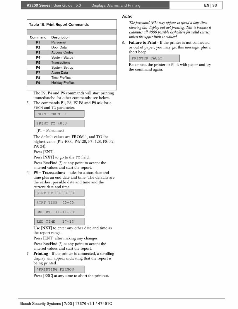
K2200 Series | User Guide | 5.0 Displays, Alarms, and Printing EN | 33
Bosch Security Systems | 7/03 | 17376 v1.1 / 47491C
Table 15: Print Report Commands
Command DescriptionP1 PersonnelP2 Door DataP3 Access CodesP4 System StatusP5 TransactionsP6 System Set upP7 Alarm DataP8 Time ProfilesP9 Holiday Profiles
The P2, P4 and P6 commands will start printingimmediately; for other commands, see below.
5. The commands P1, P3, P7 P8 and P9 ask for aFROM and TO parameter.
PRINT FROM 1
PRINT TO 4000
(P1 – Personnel)
The default values are FROM 1, and TO thehighest value (P1: 4000, P3:128, P7: 128, P8: 32,P9: 24).Press [ENT].Press [NXT] to go to the TO field.Press FastFind (*) at any point to accept theentered values and start the report.
6. P5 – Transactions - asks for a start date andtime plus an end date and time. The defaults arethe earliest possible date and time and thecurrent date and time.
STRT DT 00-00-00
STRT TIME 00-00
END DT 11-11-93
END TIME 17-13
Use [NXT] to enter any other date and time asthe report range.Press [ENT] after making any changes.Press FastFind (*) at any point to accept theentered values and start the report.
7. Printing - If the printer is connected, a scrollingdisplay will appear indicating that the report isbeing printed.
*PRINTING PERSON
Press [ESC] at any time to abort the printout.
Note:The personnel (P1) may appear to spend a long timeshowing this display but not printing. This is because itexamines all 4000 possible keyholders for valid entries,unless the upper limit is reduced
8. Failure to Print - If the printer is not connectedor out of paper, you may get this message, plus ashort beep.
PRINTER FAULT
Reconnect the printer or fill it with paper and trythe command again.

K2200 Series | User Guide | 5.0 Displays, Alarms, and Printing EN | 34
Bosch Security Systems | 7/03 | 17376 v1.1 / 47491C
P1 – Personnel
This report produces a list of all keyholders in the system. The PIN code will only be printer if your editorlevel allows.
Figure 13: Sample P1 – Personnel Printout
Readykey K2200 PERSONNEL REPORT
DATE: 11-11-93 TIME: 16:53 REQUESTED BY MASTER KEY PAGE 1
PERS. ID NAME TOKEN CODE ACCESS CODE PIN NO
0001 MASTER KEY D3062425 1 1609
0002 JONES A 8824A474 1 5613
0003 SMITH J 3A33642A 1 3446
0004 BROWN IM C824B4BC 3 8249
0005 BAXTER OT 5503E480 3 4854
0006 TAYLOR TB 8C25D403 3 1524
0007 ROYLE TS 6903F4F4 3 9099
0008 LEE SA 230314F3 3 9030
0009 LIDDY BP C824942B 3 2941
0010 BORRELL LA 4E02C491 3 54350011 WALKER STM 74665451 3 6736
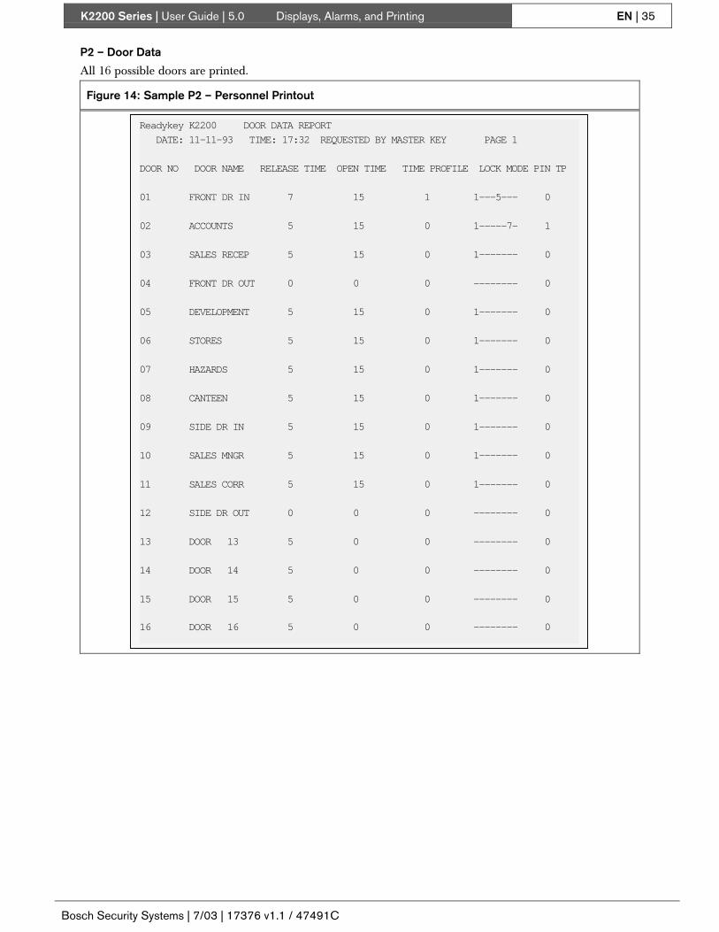
K2200 Series | User Guide | 5.0 Displays, Alarms, and Printing EN | 35
Bosch Security Systems | 7/03 | 17376 v1.1 / 47491C
P2 – Door Data
All 16 possible doors are printed.
Figure 14: Sample P2 – Personnel Printout
Readykey K2200 DOOR DATA REPORT
DATE: 11-11-93 TIME: 17:32 REQUESTED BY MASTER KEY PAGE 1
DOOR NO DOOR NAME RELEASE TIME OPEN TIME TIME PROFILE LOCK MODE PIN TP
01 FRONT DR IN 7 15 1 1---5--- 0
02 ACCOUNTS 5 15 0 1-----7- 1
03 SALES RECEP 5 15 0 1------- 0
04 FRONT DR OUT 0 0 0 -------- 0
05 DEVELOPMENT 5 15 0 1------- 0
06 STORES 5 15 0 1------- 0
07 HAZARDS 5 15 0 1------- 0
08 CANTEEN 5 15 0 1------- 0
09 SIDE DR IN 5 15 0 1------- 0
10 SALES MNGR 5 15 0 1------- 0
11 SALES CORR 5 15 0 1------- 0
12 SIDE DR OUT 0 0 0 -------- 0
13 DOOR 13 5 0 0 -------- 0
14 DOOR 14 5 0 0 -------- 0
15 DOOR 15 5 0 0 -------- 0
16 DOOR 16 5 0 0 -------- 0

K2200 Series | User Guide | 5.0 Displays, Alarms, and Printing EN | 36
Bosch Security Systems | 7/03 | 17376 v1.1 / 47491C
P3 – Access Data
This report lists all the access codes, broken down into the primary access level and time profile, andsecondary access level and time profile.
Figure 15: Sample P3 – Access Data Printout
Readykey K2200 ACCESS DATA REPORT
DATE: 11-11-93 TIME: 10:21 REQUESTED BY MASTER KEY PAGE 1
ACC CODE DOORS ACCESSED TIME PROFILE TIME PERIODS
001 1-12 Primary : 000 Period - not assigned
Period - not assigned
Period - not assigned
Secondary : 000 Period - not assigned
Period - not assigned
Period - not assigned
002 1,4,8,9,12 Primary : 001 Period 01 08-45 - 17-30 on MTWTF--H
Period 02 08-45 - 13-00 on -----SSH
Period - not assigned
Secondary : 000 Period - not assigned
Period - not assigned
Period - not assigned
003 1-12 Primary : 001 Period 01 08-45 - 17-30 on MTWTF--H
Period 02 08-45 - 13-00 on -----SSH
Period - not assigned
3,11 Secondary : 001 Period 01 08-45 - 17-30 on MTWTF--H
Period 02 08-45 - 13-00 on -----SSH Period - not assigned
P4 – System Status
This report shows the state of doors and alarm zones within the system. The doors and alarm zones are shownfor each door controller in turn.

K2200 Series | User Guide | 5.0 Displays, Alarms, and Printing EN | 37
Bosch Security Systems | 7/03 | 17376 v1.1 / 47491C
Table 16: System Status – Doors and Alarm Zones
System Parameter Display Message DescriptionUNLOCKED Door is manually or automatically unlocked, see OverrideLOCKED The door requires a valid key
Doors Door States
OPEN The door is physically openNO ALARM No alarm conditions presentTAMPER/FORCED A Tamper or Unauthorized Access
Door Alarm States
LEFT OPEN Door left openYES If doors all doors opened,Emergency Override?NO Normal condition.NORMAL No override activeUNLOCK Door manually unlocked (L Command)
Manual Override?
LOCKED Door manually locked (L Command)YES Door opened on a time profileTimed Override?NO No active time profile
Alarm Zone States - Only alarm module Inputs that have been assigned responses are shown.YES Isolated, either manually or by a time profileIsolated?NO Zone is activeCLEAR Input is in its normal conditionStateALARM Input is in alarm state
Figure 16: Sample P4 - System Status Printout
Readykey K2200 DOOR AND ALARM STATUS REPORT
DATE: 11-11-93 TIME: 10:24 REQUESTED BY MASTER KEY PAGE 1
DOOR CONTROLLER : 01
DOOR DOOR NAME STATE ALARM STATE EMERGENCY MANUAL TIMED
OVERRIDE? OVERRIDE? OVERRIDE?
01 FRONT DR IN UNLOCKED NO ALARM NO NORMAL YES
02 ACCOUNTS OPEN FORCED/TAMPER NO NORMAL NO
03 SALES RECEP LOCKED NO ALARM NO NORMAL NO
04 FRONT DR OUT UNLOCKED NO ALARM NO NORMAL NO
ALARM ZONE STATUS
ZONE NO ISOLATED? STATE
1 YES INPUT CLEAR2 YES INPUT CLEAR
P5 – Transaction Printout
The P5 command prompts you for a date and time range.
Note:The printout will give all the high priority transactions that have occurred in the date range first, followed by the rest ofthe transactions. This may result in a pause between the two parts of the report.
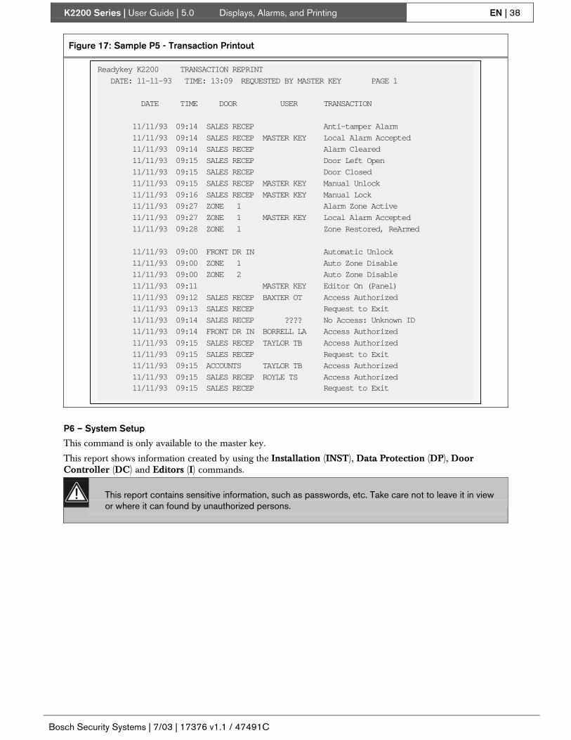
K2200 Series | User Guide | 5.0 Displays, Alarms, and Printing EN | 38
Bosch Security Systems | 7/03 | 17376 v1.1 / 47491C
Figure 17: Sample P5 - Transaction Printout
Readykey K2200 TRANSACTION REPRINT
DATE: 11-11-93 TIME: 13:09 REQUESTED BY MASTER KEY PAGE 1
DATE TIME DOOR USER TRANSACTION
11/11/93 09:14 SALES RECEP Anti-tamper Alarm
11/11/93 09:14 SALES RECEP MASTER KEY Local Alarm Accepted
11/11/93 09:14 SALES RECEP Alarm Cleared
11/11/93 09:15 SALES RECEP Door Left Open
11/11/93 09:15 SALES RECEP Door Closed
11/11/93 09:15 SALES RECEP MASTER KEY Manual Unlock
11/11/93 09:16 SALES RECEP MASTER KEY Manual Lock
11/11/93 09:27 ZONE 1 Alarm Zone Active
11/11/93 09:27 ZONE 1 MASTER KEY Local Alarm Accepted
11/11/93 09:28 ZONE 1 Zone Restored, ReArmed
11/11/93 09:00 FRONT DR IN Automatic Unlock
11/11/93 09:00 ZONE 1 Auto Zone Disable
11/11/93 09:00 ZONE 2 Auto Zone Disable
11/11/93 09:11 MASTER KEY Editor On (Panel)
11/11/93 09:12 SALES RECEP BAXTER OT Access Authorized
11/11/93 09:13 SALES RECEP Request to Exit
11/11/93 09:14 SALES RECEP ???? No Access: Unknown ID
11/11/93 09:14 FRONT DR IN BORRELL LA Access Authorized
11/11/93 09:15 SALES RECEP TAYLOR TB Access Authorized
11/11/93 09:15 SALES RECEP Request to Exit
11/11/93 09:15 ACCOUNTS TAYLOR TB Access Authorized
11/11/93 09:15 SALES RECEP ROYLE TS Access Authorized 11/11/93 09:15 SALES RECEP Request to Exit
P6 – System Setup
This command is only available to the master key.
This report shows information created by using the Installation (INST), Data Protection (DP), DoorController (DC) and Editors (I) commands.
This report contains sensitive information, such as passwords, etc. Take care not to leave it in viewor where it can found by unauthorized persons.
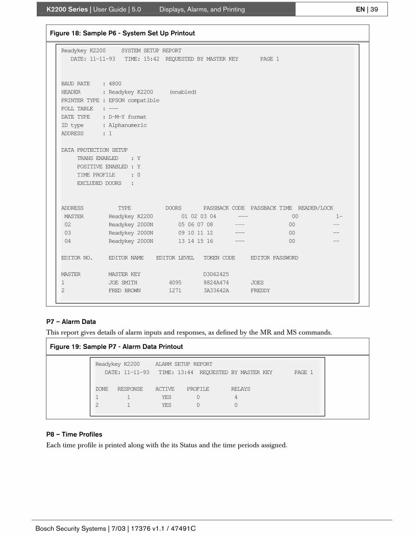
K2200 Series | User Guide | 5.0 Displays, Alarms, and Printing EN | 39
Bosch Security Systems | 7/03 | 17376 v1.1 / 47491C
Figure 18: Sample P6 - System Set Up Printout
Readykey K2200 SYSTEM SETUP REPORT
DATE: 11-11-93 TIME: 15:42 REQUESTED BY MASTER KEY PAGE 1
BAUD RATE : 4800
HEADER : Readykey K2200 (enabled)
PRINTER TYPE : EPSON compatible
POLL TABLE : ---
DATE TYPE : D-M-Y format
ID type : Alphanumeric
ADDRESS : 1
DATA PROTECTION SETUP
TRANS ENABLED : Y
POSITIVE ENABLED : Y
TIME PROFILE : 0
EXCLUDED DOORS :
ADDRESS TYPE DOORS PASSBACK CODE PASSBACK TIME READER/LOCK
MASTER Readykey K2200 01 02 03 04 --- 00 1-
02 Readykey 2000N 05 06 07 08 --- 00 --
03 Readykey 2000N 09 10 11 12 --- 00 --
04 Readykey 2000N 13 14 15 16 --- 00 --
EDITOR NO. EDITOR NAME EDITOR LEVEL TOKEN CODE EDITOR PASSWORD
MASTER MASTER KEY D3062425
1 JOE SMITH 4095 8824A474 JOES2 FRED BROWN 1271 3A33642A FREDDY
P7 – Alarm Data
This report gives details of alarm inputs and responses, as defined by the MR and MS commands.
Figure 19: Sample P7 - Alarm Data Printout
Readykey K2200 ALARM SETUP REPORT
DATE: 11-11-93 TIME: 13:44 REQUESTED BY MASTER KEY PAGE 1
ZONE RESPONSE ACTIVE PROFILE RELAYS
1 1 YES 0 42 1 YES 0 0
P8 – Time Profiles
Each time profile is printed along with the its Status and the time periods assigned.

K2200 Series | User Guide | 5.0 Displays, Alarms, and Printing EN | 40
Bosch Security Systems | 7/03 | 17376 v1.1 / 47491C
Figure 20: Sample P8 - Time Profile Printout
Readykey K2200 TIME PROFILE REPORT
DATE: 11-11-93 TIME: 16:01 REQUESTED BY MASTER KEY PAGE 1
PROFILE ACTIVE PROFILE DETAILS
1 YES Period 01 08:45 - 17:30 on MTWTF--H
Period 02 08:45 - 13:00 on -----SSH
Period - not assigned
2 NO Period 03 18:00 : 23:59 on MTWTF---
Period 04 00:00 - 06:00 on -TWTFS--
Period - not assigned
P9 – Holiday Profiles
Holiday profiles are printed with all the assigned holiday periods. Holiday profile 1 contains the systemholidays.
Figure 21: Sample P9 - Holiday Profile Printout
Readykey K2200 HOLIDAY REPORT
DATE: 30-11-93 TIME: 16:05 REQUESTED BY MASTER KEY PAGE 1
PROFILE ACTIVE START DURATION START DURATION START DURATION START DURATION
1 YES 25/12/93 2 01/01/94 1 00/00/00 0 00/00/00 0
00/00/00 0 00/00/00 0 00/00/00 0 00/00/00 0
00/00/00 0 00/00/00 0 00/00/00 0 00/00/00 0
00/00/00 0 00/00/00 0 00/00/00 0 00/00/00 0
00/00/00 0 00/00/00 0 00/00/00 0 00/00/00 0
2 NO 00/00/00 0 00/00/00 0 00/00/00 0 00/00/00 0
00/00/00 0 00/00/00 0 00/00/00 0 00/00/00 0
00/00/00 0 00/00/00 0 00/00/00 0 00/00/00 0
00/00/00 0 00/00/00 0 00/00/00 0 00/00/00 0
00/00/00 0 00/00/00 0 00/00/00 0 00/00/00 0
5.5.2 Header – The HE Command
Two features are provided, the header text thatappears at the top of each page and whether or not anew page is started and a header printed at the endof each page of on-line transactions.
Header Text
The text that appears at the top of every report canbe changed to reflect the site name or any othersuitable text. Up to 30 characters can be entered,which are split into 3 'strings' of 10 characters each.
Header used in On-line Tranactions
When on-line transactions are printed they willnormally print continuously without interruption.You can, however, set the transactions to leave a gapat the end of each page and print the header at thetop of the next page.1. Present an editor key to the faceplate reader.2. Enter the password and press [ENT], if required.
3. You will now see the CMD prompt.4. Type [H][E] and press [ENT].
CMD HE_
5. Header Text 1 - Type the first 10 characters ofthe header text. Press [ENT].STR1 ReadykeyINTERN
Press [NXT] to go to the second 10 characters.6. Header Text 2 - Type the second 10 characters
of the header text. Press [ENT].
STR2 ATIONAL PA
Press [NXT] to go to the final 10 characters.7. Header Text 3 - Type the final 10 characters of
the header text. Press [ENT]
STR3 C 2244
Press [NXT] to go to the next field.8. Enable Header in On-Line Transactions

K2200 Series | User Guide | 5.0 Displays, Alarms, and Printing EN | 41
Bosch Security Systems | 7/03 | 17376 v1.1 / 47491C
HEADER ENABLE N
Type [Y] for on-line transactions to start a newpage and print the header. Press [ENT].Type [N] for continuous transaction printing,without break. Press [ENT].Press [ESC] to go back to CMD prompt.

K2200 Series | User Guide | 6.0 Installer Commands EN | 42
Bosch Security Systems | 7/03 | 17376 v1.1 / 47491C
6.0 Installer CommandsThis section describes the commands used toconfigure the door controller. Care should be takenwhen using these commands as they can change theway the whole system works. Only users andInstallers who are fully aware of the implications ofmaking changes to the system should have access tothese commands. Ideally they should be used onlyby the installer when commissioning the system.
6.1 The D CommandThe D command allows the setting of several featureson each door or reader. Each of these features isdescribed in detail below, followed by a descriptionof the D command itself.
The features are described in the order in which theyappear, and the heading for each command alsoincludes the prompt displayed when using the Dcommand.
When a door controller is first installed, if theSYSTEM START command is used (see Master KeyCommands), some values will already be set. Thesewill be indicated in the descriptions below.
6.1.1 Lock Release Time
Prompt: LRT
Range: 0 – 255 seconds
Default: 5
The amount of time, in seconds, that a lock willoperate when a valid key is presented or a Request toExit button is pressed. When setting this value,consideration should be given to the way in whichthe door operates, its location and the people whowill be using it. For instance, elderly or disabledpeople may require a longer time to open the doorafter presenting their keys.
Note:If door monitoring is enabled, the lock release time willbe cancelled when the door controller detects the doorhas closed.
6.1.2 Door Open Time
Prompt: DOT
Range: 0 – 255 seconds
Default: 0
The value entered here performs two functions,enabling door monitoring and the length of time adoor can be left open before a warning.
6.1.3 Door Monitoring
The fitting of a door monitoring switch is describedin Readykey K2200 Series Controllers Installation Guide(Bosch P/N: 46513, PAC P/N: 17375).
• If the value is non-zero (i.e. between 1 and 255),door monitoring is enabled. This means that thedoor controller expects a switch to open whenthe door is opened and to close when the door isclosed.
• If no door monitoring switch is fitted, this valueshould be set to 0.
• If a door monitoring switch is fitted and thisvalue is set to 0 and the switch will be ignored.
• If no door contact is fitted but you wish tomonitor the reader and its cable for tamperevents, a non-zero value should be entered here.The DR1 terminal of the reader channel mustalso be connected to ground at the reader.
Once door monitoring is enabled, the door controllerwill respond to alarm events and warnings. Theseare:
• Unauthorized Access The door has openedwithout a valid key being presented or aRequest to Exit switch being pressed. This eventmust be accepted by an editor key.
• Anti-Tamper The cable between the doorcontroller and reader has been broken. Thisevent must be accepted by an editor key.
• Door Left Open A warning event generatedwhen a door is left open for a period longer thanthe lock release time plus the door open time.
6.1.4 Time Profile
Prompt: TP
Range: 0 – 128
Default: 0
See Section 4.3 Time Profiles for details on creatingtime profiles.
A time profile can be used to automatically lock andunlock a door at set times of the day and days of theweek. A typical example would be a public accessdoor that is unlocked during office hours to allownon-keyholders to enter but requires a key at allother times. The time profile could also preventunlocking on public holidays, such as Christmas, etc.
If you have no intention of automatically unlocking adoor, set the value to 0.
The value entered is the number of the time profilethat will control automatic locking and unlocking. Itis recommended that time profiles used forcontrolling doors are not used for any other purpose.This allows changes to be made to door control,without inadvertently disturbing other timecontrolled functions, such as access codes, alarmzones, etc.
Automatic Lock and Automatic Unlocktransactions are generated on each occasion.

K2200 Series | User Guide | 6.0 Installer Commands EN | 43
Bosch Security Systems | 7/03 | 17376 v1.1 / 47491C
• If a value of 0 is used, a key will be required atall times.
• If a time profile is disabled, the door it isassigned to will lock (if it is unlocked) and a key
will be required at all times until the time profileis enabled again.
Mode 1
Prompt: M
Range: 8 options
Default: All unset
This option field controls 8 different settingscontrolling the operation of the reader and lock.They are:
Table 17: Reader and Lock Operation Settings – Mode 1
Option Type DescriptionUnset: Power to unlock, fail-secure
Power to lock, fail-safe1 Lock Type
If you using a power to lock (or fail-safe) locking device, this option should be set. Inthis case, power will be provided continuously and removed to release the lock. Ifunset, power will be provided to operate the lockUnset: Normal OperationSet: Emergency Override/Free ExitThe operation of this option is described in detail in the Readykey K2200 SeriesControllers Installation Guide (Bosch P/N: 46513, PAC P/N: 17375).
When unset the DR1 inputs operate normally:DR1 the door contact switch, if fitted, monitors the door positionDR2 the Request to Exit switchWhen this option is set, the operation of the DR1 and DR2 inputs is altered:DR1 the door contact switch, produces a Free Exit transaction. It may also
operate as a Request to Exit switch, in that if it is opened the lock willalso operate. A door open time must be set to allow this feature tooperate. Door left open reports will also be generated if it is used asa door monitoring switch.
2 EmergencyOverride/Free Exit
DR2 when opened produces an Emergency Override On transaction,when closed produces an Emergency Override Offtransaction. This allows the monitoring of an emergency switch suchas a break-glass.
Unset: Normal OperationSet: Request for Entry
3 Request for Entry
When set, a Request to Exit switch will produce a Request for Entry transaction. Thisis a useful feature, for instance, when the switch is operated from inside an area tounlock a door once a person outside has been recognized. This may the case whenusing audio or video entry systems.Unset: No AVR attachedSet: AVR
4 Readykey AVR(Automatic VehicleRecognition) Only set this option when a Readykey AVR reader module is attached to the reader
channel.Unset: No Readykey Alarm Module/Readykey Alarm Event Manager
attached.Set: Readykey Alarm Module/Readykey Alarm Event Manager
5 Readykey AlarmModule/ReadykeyAlarm Event Manager
Only set this option when an alarm module is fitted to the reader channel. If you setthis option when an alarm module is not attached the reader LED will flicker. Youcannot have both option 7 (PIN reader with time profiles) and a Readykey AlarmModule set on the same channel.Unset Normal Operation6 Exit Out of HoursSet Exit Out Of Hours

K2200 Series | User Guide | 6.0 Installer Commands EN | 44
Bosch Security Systems | 7/03 | 17376 v1.1 / 47491C
Table 17: Reader and Lock Operation Settings – Mode 1
Option Type DescriptionWhen set, this option allows people to use a door when their time profile hasexpired. This would normally be the case for an exit door, where people would belocked in they failed to leave before their time profile expired. An Exit out ofHours report is generated when set.Unset No Readykey PIN reader with time profiles fittedSet Readykey PIN reader with time profiles fitted.
7 PIN Reader with TimeProfiles
Only use this option if a Readykey PIN reader with time profiles is fitted to the readerchannel. Do not set this option if any other type of PIN reader is fitted. You cannothave both option 5 (alarm module) and a PIN reader with time profiles set on thesame channel.
8 Not Used Leave Unset
Mode 2
Prompt: M2
Range: 8 options
Default: All unset
This option field controls an additional 8 differentsettings of which only three are currently used,controlling the operation of the reader and lock.They are:
Table 18: Reader and Lock Operation Settings - Mode 2
Option Type DescriptionUnset RTE with Lock Output (normal operation)Set E with no Lock Output
1 Request to ExitWithout LockActivation This option is designed for use on the secure side of a door where exit is via a handle
etc. Pressing the Request to Exit switch simply informs the system that someone hasleft the areaUnset Lock release time operates normally2 Lock as Soon as
Possible Set Lock de-activated a maximum of 2 seconds after the door is opened.Unset All events are loggedSet Events only logged if the door is opened
3 Log on Door EntryOnly
When set, if a key is presented to a door but the door isn’t opened, the event will notbe logged.
4 - 8 Not currently used.
6.1.5 Door Name
Prompt: ID
Default: DOOR nn = 1 to 16
Use this field to give the door a useful name. Thisname, which may contain up to 12 letters (A-Z),numbers (0-9) and spaces (SPC), will appear on allprinted reports.
6.1.6 PIN Reader Time Profile
Prompt: PINTP
Range: 0 – 128
Default: 0
A PIN reader with time profiles provides two levelsof security. When the time profile is active, a validkey alone will allow access, when the time profile isinactive, a valid key plus the correct PIN is required.If a time profile of 0 is used, a valid key plus PIN willalways be required.
An example may be a door that only requires a keyduring normal office hours but requires a key plusPIN at any other time.

K2200 Series | User Guide | 6.0 Installer Commands EN | 45
Bosch Security Systems | 7/03 | 17376 v1.1 / 47491C
6.1.7 Using the D Command
Each of the settings in the D command is fullydescribed above.1. Present an editor key to the faceplate reader.2. Enter the password and press [ENT], if required.3. You will now see the CMD prompt.4. Type [D] and press [ENT].
CMD D_
5. Use the up and down arrow keys to select thedoor.Enter a value, in seconds, between 0 and 255 forthe amount of time the lock will operate. Press[ENT].
DR 1 LRT 5
Press [NXT] to go to the next field.6. A value greater than zero enables door
monitoring. The value entered is the time inseconds that, when added to the lock releasetime, a door left open warning will be generated.Press [ENT]
DR 1 TP 0
Press [NXT] to go to the next field.7. Lock Mode Options - This is an option field. To
change a setting press the number correspondingto the option you want to change. If an option isset, its number will be displayed, if not set, a -(dash) will be displayed.
Table 19: Lock Mode Options
Option DescriptionUnset Fail-secure lock1Set Fail-safe lockUnset Normal RTE, door contact2Set Emergency override, free exitUnset Normal RTE report3Set Request for entry reportUnset No AVR module4Set AVR module attachedUnset No alarm module5Set Alarm module attachedUnset Normal operation6Set Exit out of hours allowedUnset No PIN reader with time profiles7Set PIN reader with time profiles
attached8 Not Used, leave Unset
Press [ENT] when all required options are set.Press [NXT] to go to the next field.
8. Door 1, Lock Mode 2 (Options) - This displayconsists of 8 more option settings representedeither by a number or a - (dash). Each setting ischanged by pressing a number between 1 and 8.When set, the number will appear: when not set,a - (dash) will replace the number. At startup, allsettings will be off.
DR 1 M2--------
Table 20: Lock Mode 2 Options
Options DescriptionSet: RTE with no lock output. This is
designed for use on the secureside of a door where exit is via amechanical handle, etc. Pressingthe Request to Exit switch shuntsthe door contact but does notactivate the lock.
1
Unset: RTE with lock output. This is thedefault setting. When the Requestto Exit switch is pressed, the lockstate is changed and the door canbe opened.
Set: Early lock release time. When set,the lock is de-activated a maximumof two seconds after the door isopened.
Unset: lock release time operates normally
2
Lock is de-activated when the lock releasetime expires or the door closes.Set: Log authorized event only when
door opened. When set,authorized events are only reportedif the door is opened.
3
Unset: All events are logged whether ornot the door is opened
4 ElevatorControl:
This option is not userconfigurable and is set usingReadykey for Windows
5 – 8 These settings are not currently used.
Press [NXT] to go to the next field. (Rememberto press [ENT] to save changes).
9. PIN Reader Time Profile - Only used when aReadykey PIN reader with time profiles isattached. When the time profile is active, only avalid key is required; when inactive, a valid keyplus PIN is required for access. A time profile of0 requires a valid key plus PIN at all times. Press[ENT].
DR 1 PINTP 0
Press [ESC] to return to the CMD prompt.

K2200 Series | User Guide | 6.0 Installer Commands EN | 46
Bosch Security Systems | 7/03 | 17376 v1.1 / 47491C
6.2 Alarm Event Manager and RelayOutputs
6.2.1 Overview
The Alarm Event Manager is an optional alarmmodule that can be attached to any reader channel. Itcan be attached at any point in the cable between thedoor controller and reader. The alarm module has 8inputs and 8 relay outputs but relays 5 to 8 can onlyadministrated by Readykey for Windows.
8 Monitored Inputs
Each alarm module can monitor up to 8 inputs andgenerate an alarm if any enabled input is activated.
Each input may be:
• Normally Open or Normally Closed (set on themodule itself)
• Enabled/Disabled Manually
• Enabled/Disabled using a time profile
• Programmed to activate a relay.
8 Relay Outputs
The 8 relay outputs on the module may be activatedby:
• An monitored input being activated.
• A system event.
• A time profile.
6.2.2 Identiying Modules, Inputs and Relays
Each reader channel on a door controller may havean alarm module connected. This means a maximumof 16 modules per system (four on each doorcontroller, although only two on a Readykey K1200).
Each alarm module has 8 possible inputs. These arenumbered 1 to 8 on each alarm module. Whenreporting, however, the zone number, 1 to 128, isused. The zone number is as shown in the followingtable.
Table 21: Zone Number
Zone NumbersInput Number:
Location
1 2 3 4 5 6 7 8Door Controller 1Alarm Module 1 1 2 3 4 5 6 7 8Alarm Module 2 9 10 11 12 13 14 15 16Alarm Module 3 * 17 18 19 20 21 22 23 24Alarm Module 4 * 25 26 27 28 29 30 31 32Door Controller 2Alarm Module 5 33 34 35 36 37 38 39 40Alarm Module 6 41 42 43 44 45 46 47 48Alarm Module 7 * 49 50 51 52 53 54 55 56Alarm Module 8 * 57 58 59 60 61 62 63 64Door Controller 3Alarm Module 9 65 66 67 68 69 70 71 72Alarm Module 10 73 74 75 76 77 78 79 80Alarm Module 11 * 81 82 83 84 85 86 87 88Alarm Module 12 * 89 90 91 92 93 94 95 96Door Controller 4Alarm Module 13 97 98 99 100 101 102 103 104Alarm Module 14 105 106 107 108 109 110 111 112Alarm Module 15 * 113 114 115 116 117 118 119 120Alarm Module 16 * 121 122 123 124 125 126 127 128
* Not available on Readykey K1200

K2200 Series | User Guide | 6.0 Installer Commands EN | 47
Bosch Security Systems | 7/03 | 17376 v1.1 / 47491C
On a standalone system, each alarm module has 4usable relay outputs, giving a maximum number of16 on each door controller, or 64 on the wholesystem (assuming all door controllers areReadykey K2200s.) In addition, the 4 relays on eachdoor controller can be programmed in the same wayas an alarm module relay but only if reader channel4 does not have an alarm module connected.
6.2.3 Alarm Module Relays
There are three ways an output relay may beactivated:
• By a monitored input being activated using theMS command (see Alarm Module Sensors).Each monitored input may be programmed toactivate a relay on any alarm module connectedto the same door controller.
• By a system event using the RE command (seeSection 6.2.5 Relay Programming).System events include UnauthorizedAccess, Door Left Open, Door Open, etc.
• By a time profile using the RE command (seeSection 6.2.5 Relay Programming).Each relay can be activated by a time profile.
Door Controller Relays
The 8 relays on each door controller each have adefault action. The relays will operate according tothese defaults, unless programmed to do otherwise.
Table 22: Relay Defaults
Relay Description1 Activated by invalid access on door 12 Activated by invalid access on door 23 Activated by invalid access on door 34 Activated by invalid access on door 45 Activated by an Unauthorized Access or
Anti-Tamper alarms at any door on thedoor controller.
6 Activated by time profile 17 Activated by a Door Left Open event at
any door.8 Activated by Case Tamper (T+, T-)
alarm.
Door controller relays are programmed as if theywere on alarm module 4, therefore you cannotprogram relays on the door controller if an alarmmodule is present on channel 4 of the doorcontroller.
6.2.4 Alarm Module Programming – The MR andMS Commands
There are three stages to programming an alarmmodule.
• Indicate the presence of the alarm module on areader channel by setting option 5 of the lockmode using the D command (see Section 6.1.7Using the D Command).
• Define one or more input responses using theMR command (see Alarm Module Responses – TheMR Command). A response consists of two items,a manual switch (see Alarm Module Responses – TheMR Command, Time Profile) and a time profile (seeSection 4.3 Time Profiles).
• Assign a response and/or a relay activation toone or more of the alarm module inputs usingthe MS command (see Alarm Module Sensors).
Alarm Module Responses – The MR Command
There are 255 possible alarm module responses, eachconsisting of two items, a manual switch and a timeprofile. By assigning one response to several alarminputs, several inputs can be enabled and disabled atonce. For instance, if you had 10 fire doors allmonitored by alarm module inputs, by assigning thesame response they can all be enabled/disabledtogether. Alternatively if you need to control inputsindividually, you should define responses for eachinput.
Manual Switch
The manual switch allows an operator to manuallyenable/disable all inputs that are assigned theresponse.
• Transactions
Inputs that are enabled manually will produce aManual Engage transaction. Inputs that aredisabled manually will produce a ManualIsolate transaction.
Time Profile
If a time profile is part or a response, any alarminputs that are assigned that response will bedisabled while the time profile is active. Forinstance, a time profile set to 9:00am to 5:00pm,Monday to Friday, assigned to a response, willdisable all inputs with that response between thosehours.
For an alarm input to automatically enable/disablewith a time profile, it must be manually enabled first.
• Transactions
Inputs that are enabled automatically willproduce an Auto Zone Enable transaction.Inputs that are disabled automatically willproduce an Auto Zone Disable transaction.
Using the MR Command
Use the MR command to define alarm moduleresponses. These responses can then be assigned toindividual inputs using the MS command (see AlarmModule Sensors).

K2200 Series | User Guide | 6.0 Installer Commands EN | 48
Bosch Security Systems | 7/03 | 17376 v1.1 / 47491C
1. Present an editor key to the faceplate reader.2. Enter the password and press [ENT], if required.3. You will now see the CMD prompt.4. Type [M][R] and press [ENT].
CMD MR_
5. Use the up and down arrow keys to select aresponse. There are a maximum of 255responses.Manual Switch
REC 1 ON N
Type [Y] to switch on the response. Press [ENT].Type [N] to switch off the response. Press [ENT].
Note:Any points that have been assigned this response will bedisabled if you select [N], or enabled if you select [Y].
Press [NXT] to go to the next field.6. Time Profile - Enter the time profile number
used to control the response. When the timeprofile is active, any points assigned this responsewill be disabled.
REC 1 TP 0
A time profile of 0 means any points assignedthis response will be controlled only by themanual switch. Press [ENT].Press [ESC] to return to the CMD prompt..
Alarm Module Sensors
The MS Command: Each alarm module input isenabled by giving it a response number using theMR command (see Alarm Module Responses – The MRCommand) In addition, each input may beprogrammed to operate a relay on any alarm moduleon the same door controller.
Response Number
By giving one or more inputs the same responsenumber, several points can be controlled together.The number you enter is the record number of theresponse you create using the MR command.
Alarm Module Relay
Any alarm module relay on the same door controllercan be set when a point is activated. The number youenter is the number of the relay according to thetable.
Table 23: Relay Numbers
Module Location RelaysChannel 1 1 2 3 4Channel 2 5 6 7 8Channel 3* 9 10 11 12Channel 4* 13 14 15 n/a
* Not available on Readykey K1200 doorcontrollers
Note:The fourth relay on alarm module 4 is not available foralarm input activation
Using the MS Command
Use the MS command to assign responses to alarmmodule inputs. Each record contains responses for all8 inputs on each alarm module.1. Present an editor key to the faceplate reader.2. Enter the password and press [ENT], if required.3. You will now see the CMD prompt.4. Type [M][S] and press [ENT].
CMD MS_
5. Use the up and down arrow keys to select analarm module. There are a maximum of 16alarm modules.
6. Input 1 Response Number - Enter the responsenumber for this input. If you enter [0], the inputwill not be monitored at all. Press [ENT].
DR 1 IP 1 R 0
Press [NXT] to go to the next field.7. Input 1 Module Relay - Enter a relay number,
see the table above, that will be set if the input isactivated. Enter [0] for no relay activation. Press[ENT].
MODULE RELAY 0
Press [NXT] to go to the next field.8. Input 2 Response Number - Enter the response
number for this input. If you enter [0], the inputwill not be monitored at all. Press [ENT].
DR 1 IP 2 R 0
Press [NXT] to go to the next field.9. Input 2 Module Relay - Enter a relay number,
see the table above, that will be set if the input isactivated. Enter [0] for no relay activation. Press[ENT].
MODULE RELAY 0
Press [NXT] to go to the next field.Press [ESC] when you have finished.
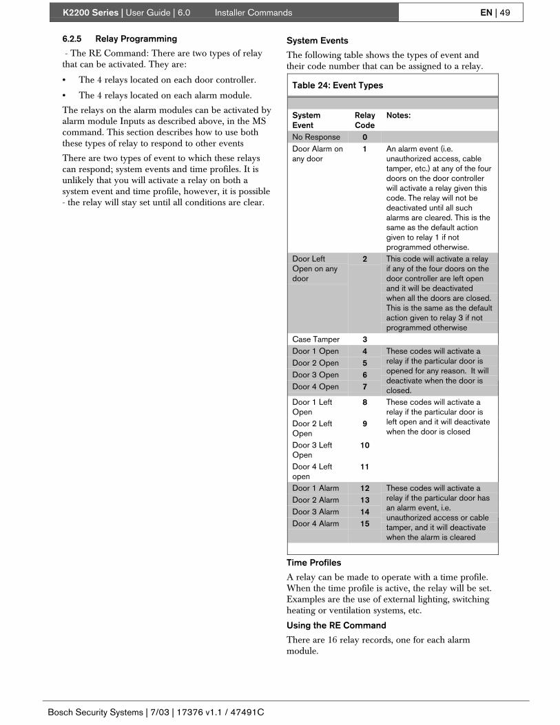
K2200 Series | User Guide | 6.0 Installer Commands EN | 49
Bosch Security Systems | 7/03 | 17376 v1.1 / 47491C
6.2.5 Relay Programming
- The RE Command: There are two types of relaythat can be activated. They are:
• The 4 relays located on each door controller.
• The 4 relays located on each alarm module.
The relays on the alarm modules can be activated byalarm module Inputs as described above, in the MScommand. This section describes how to use boththese types of relay to respond to other events
There are two types of event to which these relayscan respond; system events and time profiles. It isunlikely that you will activate a relay on both asystem event and time profile, however, it is possible- the relay will stay set until all conditions are clear.
System Events
The following table shows the types of event andtheir code number that can be assigned to a relay.
Table 24: Event Types
SystemEvent
RelayCode
Notes:
No Response 0Door Alarm onany door
1 An alarm event (i.e.unauthorized access, cabletamper, etc.) at any of the fourdoors on the door controllerwill activate a relay given thiscode. The relay will not bedeactivated until all suchalarms are cleared. This is thesame as the default actiongiven to relay 1 if notprogrammed otherwise.
Door LeftOpen on anydoor
2 This code will activate a relayif any of the four doors on thedoor controller are left openand it will be deactivatedwhen all the doors are closed.This is the same as the defaultaction given to relay 3 if notprogrammed otherwise
Case Tamper 3Door 1 Open 4Door 2 Open 5Door 3 Open 6Door 4 Open 7
These codes will activate arelay if the particular door isopened for any reason. It willdeactivate when the door isclosed.
Door 1 LeftOpen
8
Door 2 LeftOpen
9
Door 3 LeftOpen
10
Door 4 Leftopen
11
These codes will activate arelay if the particular door isleft open and it will deactivatewhen the door is closed
Door 1 Alarm 12Door 2 Alarm 13Door 3 Alarm 14Door 4 Alarm 15
These codes will activate arelay if the particular door hasan alarm event, i.e.unauthorized access or cabletamper, and it will deactivatewhen the alarm is cleared
Time Profiles
A relay can be made to operate with a time profile.When the time profile is active, the relay will be set.Examples are the use of external lighting, switchingheating or ventilation systems, etc.
Using the RE Command
There are 16 relay records, one for each alarmmodule.

K2200 Series | User Guide | 6.0 Installer Commands EN | 50
Bosch Security Systems | 7/03 | 17376 v1.1 / 47491C
To program the door controller relays, select DR 4,DR 8, DR 12, DR 16 for door controllers 1, 2, 3 and4 respectively, provided no alarm modules areinstalled on these channels.1. Present an editor key to the faceplate reader.2. Enter the password and press [ENT], if required.3. You will now see the CMD prompt.4. Type [R][E] and press [ENT].
CMD RE_
5. Door 1, Relay 1 Time Profile Number - Entera time profile number (1-128). When the timeprofile is activated, the relay will activate; whenthe time profile finishes, the relay will deactivate.A time profile of 0 will remove any timedactivation.
DR 1 RLY 1 TP 0
Press the [ENT] key.Press [NXT] to go to the next field.
6. Door 1, Relay 1 System Event - Enter a systemevent (0-15) as shown in the table above.
DR 1 RLY 1 SYS 0
Press the [ENT] key.Press [NXT] to go to the next relay.There are a total of 4 relays, each with a timeprofile and system event value.Press [ESC] to return to the CMD prompt.
Examples
To have each door controller use its four on-boardrelays to indicate Door Left Open for its ownindividual doors:1. Use the RE command and select the DR 4
record for door controller 1.2. For RLY1 SYS enter a value of 4 and press
[ENT].3. For RLY2 SYS enter a value of 5 and press
[ENT].4. For RLY3 SYS enter a value of 6 and press
[ENT].5. For RLY4 SYS enter a value of 7 and press
[ENT].If door 2 is left open relay 2 will activate and stayactivated until the door is closed.

K2200 Series | User Guide | 7.0 Troubleshooting EN | 51
Bosch Security Systems | 7/03 | 17376 v1.1 / 47491C
7.0 TroubleshootingThis section is designed to help you “troubleshoot”problems that may occur. Once the system has beeninstalled and commissioned, the majority of theproblems that are likely to occur will be due toincorrect programming of the system. Any hardwareproblems that may arise (broken cable, faulty reader,etc.) have already been dealt with in the ReadykeyK2200 Series Controllers Installation Guide (Bosch P/N:46513, PAC P/N: 17375).
Many common problems involve programming thesystem. A flowchart is provided for each problem,which takes you through a series of checks thatshould resolve the problem. The note “installer”means that it may be a hardware fault and youshould refer to Readykey K2200 Series ControllersInstallation Guide (Bosch P/N: 46513, PAC P/N: 17375).Where instructions are given (e.g. add access group),refer to the appropriate section of this document fordetails.
The following problems are covered:
• Key not working - access not allowed throughone of the doors in the system.
• No access to Editor mode.
• User cannot add/delete keys etc.
Note:It is assumed that the system has been commissionedand tested and all installation problems resolved.
7.1 End User Troubleshooting7.1.1 Key Not Working
Note:This section is primarily for use with standalonesystems. Troubleshooting for networked systems isprimarily via Readykey for Windows. However, forcompleteness, troubleshooting for the Windows system isalso included here
. When a key is presented within range of the reader theLED will flash green momentarily to indicate the codein the key has been read. If the key is valid for that doorat that time, the LED will turn green and the lock willoperate. The LED will stay green while the lock isreleased.
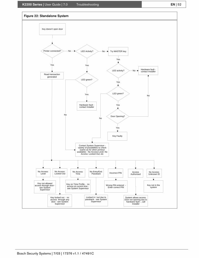
K2200 Series | User Guide | 7.0 Troubleshooting EN | 52
Bosch Security Systems | 7/03 | 17376 v1.1 / 47491C
Figure 22: Standalone System
Key doesn't open door
No Try MASTER key
LED activity? Hardware fault -contact Installer
Yes
Printer connected?
No Access:Level
Key not allowedaccess through door -
see SystemSupervisor
Key locked out - noaccess through anydoor - see System
Supervisor
Key on Time Profile - noaccess at current time -see System Supervisor
Locked in / out due topassback - see System
Supervisor
Wrong PIN entered -Enter correct PIN
Read transactiongenerated
LED Activity?
No Access:Locked Out
No Access:Time
No Entry/Exit:Passback Incorrect PIN Access
Authorised
System allows access.Door not opening due to
hardware fault -, callInstaller
No
Yes
No Access:Unknown ID
Key not in thesystem
Yes
LED green?
Yes
Door Opening?
Yes
No
Hardware fault -contact Installer
No
Contact System Supervisor -variety of possibilities to check
(same as for when printoutavailable) - No Access:Level; No
Access: Locked Out; etc
LED green?
No
Yes
Yes
No
Key Faulty

K2200 Series | User Guide | 7.0 Troubleshooting EN | 53
Bosch Security Systems | 7/03 | 17376 v1.1 / 47491C
7.1.2 No Access to Editor
This will basically happen if:
• Key is not an editor key.
• Editor key does not have the required privileges.
• Editor key is faulty.
• Editor is faulty.
Figure 23: No Access to Editor
Present Key to the Editor
T displayed?
Yes
Key not an Editor or doesnot have privileges toaccess Editor - see
System Administrator
NoPresent another known(valid) key to the Editor
T displayed? NoFault with Editor - contact
Installer
Yes
Fault with Editor - contactInstaller
Faulty key

K2200 Series | User Guide | 7.0 Troubleshooting EN | 54
Bosch Security Systems | 7/03 | 17376 v1.1 / 47491C
7.1.3 Cannot Add/Delete Keys
Figure 24: Cannot Add/Delete Keys
Present Key to the Editor
CMD displayed?
Yes
Press A to add a key (or Vto delete a key) and press
ENT
NoNot a valid Editor Key -
contact SystemAdministrator
Yes
Editor Key does not haveprivileges to Add keys
Invalid Ed Leveldisplayed?
No Add (Delete) Key
This is for caption text
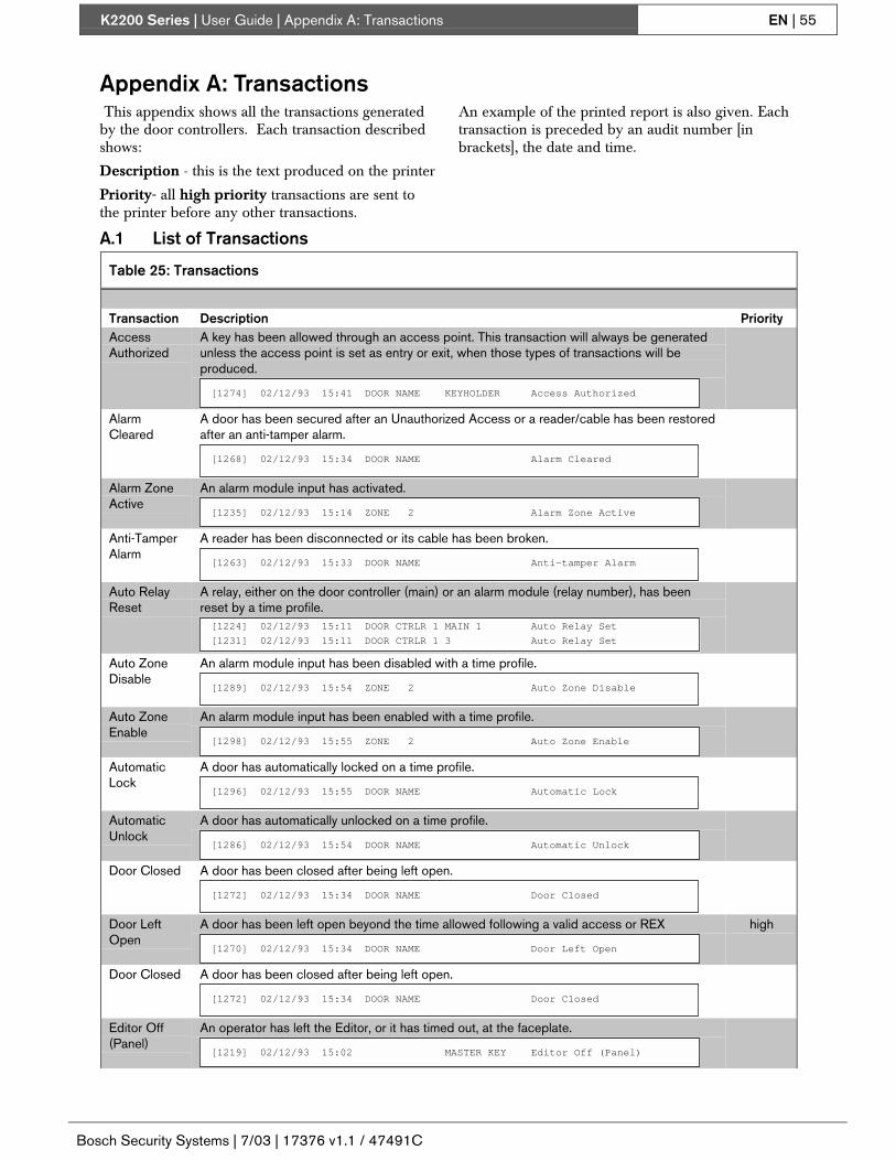
K2200 Series | User Guide | Appendix A: Transactions EN | 55
Bosch Security Systems | 7/03 | 17376 v1.1 / 47491C
Appendix A: Transactions This appendix shows all the transactions generatedby the door controllers. Each transaction describedshows:
Description - this is the text produced on the printer
Priority- all high priority transactions are sent tothe printer before any other transactions.
An example of the printed report is also given. Eachtransaction is preceded by an audit number [inbrackets], the date and time.
A.1 List of Transactions
Table 25: Transactions
Transaction Description PriorityAccessAuthorized
A key has been allowed through an access point. This transaction will always be generatedunless the access point is set as entry or exit, when those types of transactions will beproduced.
[1274] 02/12/93 15:41 DOOR NAME KEYHOLDER Access Authorized
AlarmCleared
A door has been secured after an Unauthorized Access or a reader/cable has been restoredafter an anti-tamper alarm.
[1268] 02/12/93 15:34 DOOR NAME Alarm Cleared
Alarm ZoneActive
An alarm module input has activated.
[1235] 02/12/93 15:14 ZONE 2 Alarm Zone Active
Anti-TamperAlarm
A reader has been disconnected or its cable has been broken.
[1263] 02/12/93 15:33 DOOR NAME Anti-tamper Alarm
Auto RelayReset
A relay, either on the door controller (main) or an alarm module (relay number), has beenreset by a time profile.[1224] 02/12/93 15:11 DOOR CTRLR 1 MAIN 1 Auto Relay Set
[1231] 02/12/93 15:11 DOOR CTRLR 1 3 Auto Relay Set
Auto ZoneDisable
An alarm module input has been disabled with a time profile.
[1289] 02/12/93 15:54 ZONE 2 Auto Zone Disable
Auto ZoneEnable
An alarm module input has been enabled with a time profile.
[1298] 02/12/93 15:55 ZONE 2 Auto Zone Enable
AutomaticLock
A door has automatically locked on a time profile.
[1296] 02/12/93 15:55 DOOR NAME Automatic Lock
AutomaticUnlock
A door has automatically unlocked on a time profile.
[1286] 02/12/93 15:54 DOOR NAME Automatic Unlock
Door Closed A door has been closed after being left open.
[1272] 02/12/93 15:34 DOOR NAME Door Closed
Door LeftOpen
A door has been left open beyond the time allowed following a valid access or REX
[1270] 02/12/93 15:34 DOOR NAME Door Left Open
high
Door Closed A door has been closed after being left open.
[1272] 02/12/93 15:34 DOOR NAME Door Closed
Editor Off(Panel)
An operator has left the Editor, or it has timed out, at the faceplate.
[1219] 02/12/93 15:02 MASTER KEY Editor Off (Panel)

K2200 Series | User Guide | Appendix A: Transactions EN | 56
Bosch Security Systems | 7/03 | 17376 v1.1 / 47491C
Table 25: Transactions
Transaction Description PriorityEditor On(Panel)
An operator has entered the Editor at the faceplate.
[1218] 02/12/93 15:02 MASTER KEY Editor On (Panel)
EmergencyOverride Off
Using a special lock mode option, the request to exit input can be used to monitor anemergency break-glass (manual pull station.) This transaction occurs when the switch isrestored.
[1326] 02/12/93 16:10 DOOR NAME Emergency Override Off
EmergencyOverride On
Using a special lock mode option, the request to exit input can be used to monitor anemergency break-glass (manual pull station.) This transaction occurs when the switch isbroken.
[1325] 02/12/93 16:10 DOOR NAME Emergency Override On
EntryAuthorized
A key has been allowed through an access point that was set as an entry point. This wouldbe channel 1 or 2 on a Readykey K2200 or channel 1 on a Readykey K1200. Entry and exitpoints are only used when Lock Sharing or Passback features are used.
[1321] 02/12/93 16:06 DOOR NAME KEYHOLDER Entry Authorized
ExitAuthorized
A key has been allowed through an access point that was set as an exit point. This would bechannel 3 or 4 on a Readykey K2200 or channel 2 on a Readykey K1200. Entry and exitpoints are only used when Lock Sharing or Passback features are used.
[1322] 02/12/93 16:06 DOOR NAME KEYHOLDER Exit Authorized
Exit Out ofHours
A key has been allowed to pass through an exit door, although a time profile would notnormally let the key through. A special lock mode option needs to be set on the door to allowthis feature.
[1342] 02/12/93 16:06 DOOR NAME KEYHOLDER Exit Out of Hours
Free Exit This is a special condition where a door contact is fitted but no request to exit button isused. Every time the door opens without a key being used this transaction will be generated.A special lock mode option is required.
[1327] 02/12/93 16:10 DOOR NAME Free Exit
Incorrect PINEntry
A keyholder has made 5 attempts to enter a PIN at a K2001-P reader without success. Thatkey will not be accepted for 2 hours.
[1306] 02/12/93 15:59 DOOR NAME KEYHOLDER Incorrect PIN Entry
Local AlarmAccepted
An alarm has been accepted at the door controller by presenting an Editor key.
[1237] 02/12/93 15:14 DOOR NAME MASTER KEY Local Alarm Accepted
Local DuressAccepted
A PIN Duress Alarm has been accepted by an operator at the door controller
[1320] 02/12/93 16:03 DOOR NAME MASTER KEY Local Duress Accepted
LocalOverrideAccept
An Override Alarm has been accepted by an operator at the door controller.
[1365] 02/12/93 16:20 DOOR CTRLR 1 MASTER KEY Local Override Accept
ManualEngage
An alarm module input has been switched on by an operator.
[1359] 02/12/93 16:16 ZONE 2 Manual Engage
ManualIsolate
An alarm module input has been disabled by an operator.
[1357] 02/12/93 16:16 ZONE 2 Manual Isolate
Manual Lock An operator has manually locked a door unlocked by a time profile, or previously unlockedmanually.
[1343] 02/12/93 16:14 DOOR NAME MASTER KEY Manual Lock

K2200 Series | User Guide | Appendix A: Transactions EN | 57
Bosch Security Systems | 7/03 | 17376 v1.1 / 47491C
Table 25: Transactions
Transaction Description PriorityManualUnlock
An operator has manually unlocked a door (see above.)
[1342] 02/12/93 16:14 DOOR NAME MASTER KEY Manual Unlock
No Access:Holiday
A key has been presented, but a holiday period has been assigned to this keyholder’s timeprofile.
[1444] 02/12/93 16:02 DOOR NAME KEYHOLDER No Access: Holiday
high
No Access:Level
A key has been presented, but the access level assigned to the access code does notinclude this door.
[1451] 02/12/93 16:03 DOOR NAME KEYHOLDER No Access: Level
high
No Access:Locked Out
A key has been presented, but it is not been assigned any access code.
[1217] 02/12/93 15:02 DOOR NAME KEYHOLDER No Access: Locked Out
high
No Access:Time
A key has been presented, but is not allowed through this door at this time.
[1456] 02/12/93 17:04 DOOR NAME KEYHOLDER No Access: Time
high
No Access:Unknown ID
A key has been presented, but its passcode is unknown to the door controller.
[1362] 02/12/93 16:19 DOOR NAME ???? No Access: Unknown ID
high
No Entry:Passback
A key has been presented, but will not be allowed through this door until it has left the pass-back area.
[1466] 02/12/93 17:06 DOOR NAME KEYHOLDER No Entry: Pass Back
high
No Exit:Passback
A key has been presented, but will not be allowed through this door until it has entered thepass-back area.
[1475] 02/12/93 17:08 DOOR NAME KEYHOLDER No Exit: Passback
high
OverrideAlarm
An override alarm input has opened all the doors attached to the door controller.
[1363] 02/12/93 16:20 DOOR CTRLR 1 Override Alarm
high
OverrideAlarm Reset
The override input has been cleared, all the doors will close again.
[1364] 02/12/93 16:20 DOOR CTRLR 1 Override Alarm Reset
high
PIN ReaderDuressAlarm
A PIN duress code has been entered on a K2001-P(PIN +1) and the door has opened.
[1319] 02/12/93 16:03 DOOR NAME KEYHOLDER PIN Reader Duress Alarm
high
Power Off The door controller has had its power removed, or the Reset button has been pressed.
[1222] 02/12/93 15:11 DOOR CTRLR 1 Power Off
high
Power On The door controller has been powered up, or the Reset button has been released.
[1223] 02/12/93 15:11 DOOR CTRLR 1 Power On
high
RepeatedKey Use
The same key has been presented continuously to a reader for 5 lock operations and thedoor has closed.
[1252] 02/12/93 15:20 DOOR NAME KEYHOLDER Repeated Token Use
Request forEntry
A special lock mode option can be used to allow a Request for Entry transaction. This maybe used when a button is used from inside an area to allow a person access.
[1481] 02/12/93 17:09 DOOR NAME Request for Entry
Request toExit
The Request to Exit switch has been used to open a door.
[1240] 02/12/93 15:19 DOOR NAME Request to Exit
high
RTE ButtonHeld Down
A Request to Exit button has been continuously operated 5 times and the door has closed
[1246] 02/12/93 15:20 DOOR NAME RTE Button Held Down
high

K2200 Series | User Guide | Appendix A: Transactions EN | 58
Bosch Security Systems | 7/03 | 17376 v1.1 / 47491C
Table 25: Transactions
Transaction Description PriorityUnauthorizedAccess
A door has been opened without a key being presented or the Request to Exit beingpressed.
[1258] 02/12/93 15:21 DOOR NAME Unauthorized Access
high
ZoneRestored &ReArmed
An alarm module input has been restored, and if reactivated will cause another alarm.
[1239] 02/12/93 15:14 ZONE 2 Zone Restored, ReArmed
high
A.2 High Priority TransactionsThese transactions are always sent to the printer before any other transactions.
• Alarm Cleared
• Alarm Zone Active
• Anti-Tamper Alarm
• Door Closed
• Door Left Open
• Emergency Override Off
• Emergency Override On
• Incorrect PIN Entry
• Local Alarm Accepted
• Local Duress Accepted
• Local Override Accept
• Manual Lock
• Manual Unlock
• No Access: Holiday
• No Access: Level
• No Access: Locked Out
• No Access: Time
• No Access: Unknown ID
• No Entry: Passback
• No Exit: Passback
• Override Alarm
• Override Alarm Reset
• PIN Reader Duress Alarm
• Power Off
• Power On
• Repeated Key Use
• RTE Button Held Down
• Unauthorized Access
• Zone Restored & ReArmed

K2200 Series | User Guide | Index EN | 59
Bosch Security Systems | 7/03 | 17376 v1.1 / 47491C
Index
?? Key
Inside the Editor .............................................................13
AA Command........................................................................18AC Command .....................................................................23Accept Alarms ....................................................................10Access Code
Overview ........................................................................21Access Codes ......................................................................17
Creating ..........................................................................22Organizing......................................................................21Residential Systems........................................................21Setting ............................................................................23The AC Command..........................................................23
Access LevelCreate/Amend.................................................................22
Access Levels .....................................................................22Access System
Components......................................................................8Add Editor Key...................................................................12Adding Keys
A Command ...................................................................18Administering the System...................................................10Administration Systems........................................................9AL Command .....................................................................22Alarm Acceptance...............................................................10Alarm Activations...............................................................28Alarm Event Manager (AEM) ..............................................9Alarm Event Manager and Relay Outputs ..........................46Alarm Module Programming..............................................47Alarm Module Relay ..........................................................48Alarm Module Relays.........................................................47Alarm Module Sensors .......................................................48Alarm Modules .....................................................................9Alarms ................................................................................28
Accepting Alarms...........................................................28Alarm Activations ..........................................................28Uncleared Alarms...........................................................31
Alphanumeric Keys ............................................................15Assigning Editor Commands ..............................................11
BBOSCH Alarm Event Manager (AEM) ................................9BOSCH Alarm Module ........................................................9
CCannot Add/Delete Keys ....................................................54Changing Data Fields..........................................................15Changing Date and Time
C Command....................................................................27CLR Key.............................................................................15CMD
Command Prompt...........................................................13Command Prompt - CMD...................................................13Commands
A Command ...................................................................18AC Command
Access Codes .............................................................23
C CommandDate and Time........................................................... 27
D CommandDoor/Reader features ................................................ 42
E CommandEditing Keys.............................................................. 19
HP CommandHoliday Profiles ........................................................ 24
HR CommandHoliday Periods......................................................... 24
I Command .................................................................... 11Installer .......................................................................... 42L Command
Manual Lock/Unlock ................................................ 27N Command
PIN Codes ................................................................. 20PR Command................................................................. 26T Command
creating a Time Profile.............................................. 26Creating a Time Profile ............................................. 26
V CommandDeleting Keys............................................................ 18
Communication Errors....................................................... 31Controlling Access............................................................. 20Creating Access Codes ...................................................... 22
DD Command
Door Name .................................................................... 44Door Open Time............................................................ 42Lock Mode Options ....................................................... 43Lock Release TIme........................................................ 42PIN Reader Time Profile ............................................... 44Time Profile................................................................... 42Using the D Command .................................................. 45
DataAlphabetic ..................................................................... 15Numeric ......................................................................... 16Options .......................................................................... 16
Date and TimeChanging
C Command .............................................................. 27Daylight Saving ................................................................. 27Delete Editor Key .............................................................. 12Deleting Keys .................................................................... 18Displays ............................................................................. 28
Accepting Alarms.......................................................... 28Alarms ........................................................................... 28Doors Unlocked............................................................. 28Master Controller........................................................... 28Normal Operation.......................................................... 28Slave Controller............................................................. 28
Door Controller Relays ...................................................... 47Door Controllers .................................................................. 8Door features
Door Open Time............................................................ 42Door Features
Door Left Open.............................................................. 42Door Monitoring............................................................ 42Lock Mode Options ....................................................... 43Lock Release Time ........................................................ 42
Door Left Open .................................................................. 42Door Monitoring ................................................................ 42Door Name......................................................................... 44Door Open Time ................................................................ 42
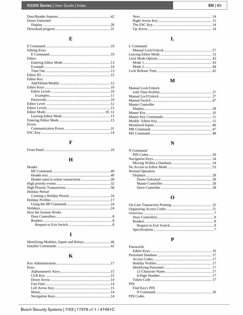
K2200 Series | User Guide | Index EN | 60
Bosch Security Systems | 7/03 | 17376 v1.1 / 47491C
Door/Reader features ..........................................................42Doors Unlocked
Display ...........................................................................28Download progress .............................................................31
EE Command ........................................................................19Editing Keys
E Command....................................................................19Editor
Entering Editor Mode.....................................................13Example..........................................................................14Time Out ........................................................................13
Editor ID .............................................................................12Editor Key
Add/Delete/Modify ........................................................12Editor Keys .........................................................................10
Editor Levels ..................................................................10Examples....................................................................11
Passwords .......................................................................10Editor Level ........................................................................12Editor Levels.......................................................................13Editor Mode ..................................................................10, 12
Leaving Editor Mode......................................................13Entering Editor Mode .........................................................13Errors
Communication Errors ...................................................31ESC Key .............................................................................14
FFront Panel..........................................................................10
HHeader
HE Command.................................................................40Header text .....................................................................40Header used in online transactions .................................40
High priority events ............................................................32High Priority Transactions..................................................58Holiday Period
Creating a Holiday Period ..............................................24Holiday Profiles ..................................................................17
Using the HP Command.................................................24Holidays..............................................................................24How the System Works
Door Controllers...............................................................8Readers .............................................................................8
Request to Exit Switch.................................................8
IIdentifying Modules, Inputs and Relays .............................46Installer Commands ............................................................42
KKey Administration.............................................................17Keys
Alphanumeric Keys........................................................15CLR Key ........................................................................15Down Arrow...................................................................14Fast Find.........................................................................14Left Arrow Key ..............................................................15Minus..............................................................................14Navigation Keys .............................................................14
Next ............................................................................... 14Right Arrow Key ........................................................... 15The ESC Key................................................................. 14Up Arrow....................................................................... 14
LL Command
Manual Lock/Unlock..................................................... 27Leaving Editor Mode ......................................................... 13Lock Mode Options ........................................................... 43
Mode 1........................................................................... 43Mode 2........................................................................... 44
Lock Release Time ............................................................ 42
MManual Lock/Unlock
with Time Profiles ......................................................... 27Manual Locl/Unlock .......................................................... 27Manual Switch ................................................................... 47Master Controller
Display........................................................................... 28Master Key......................................................................... 10Master Key Commands...................................................... 11Modify Editor Key............................................................ 12Monitored Inputs................................................................ 46MR Command.................................................................... 47MS Command .................................................................... 48
NN Command
PIN Codes...................................................................... 20Navigation Keys................................................................. 14
Moving Within a Database ............................................ 14No Access to Editor Mode ................................................. 53Normal Operation
Displays ......................................................................... 28Doors Unlocked ........................................................ 28Master Controller ...................................................... 28Slave Controller ........................................................ 28
OOn-Line Transaction Printing ............................................ 32Organizing Access Codes .................................................. 21Overview.............................................................................. 7
Door Controllers .............................................................. 8Readers ............................................................................ 8
Request to Exit Switch ................................................ 8Specifications .................................................................. 7
PPasswords
Editor Keys.................................................................... 10Personnel Database ............................................................ 17
Access Codes................................................................. 17Holiday Profiles............................................................. 17Identifying Personnel..................................................... 17
12-Character Name ................................................... 174-Digit Number ......................................................... 17
Token Code ................................................................... 17PIN
Find Key's PINN Command .............................................................. 20
PIN Codes
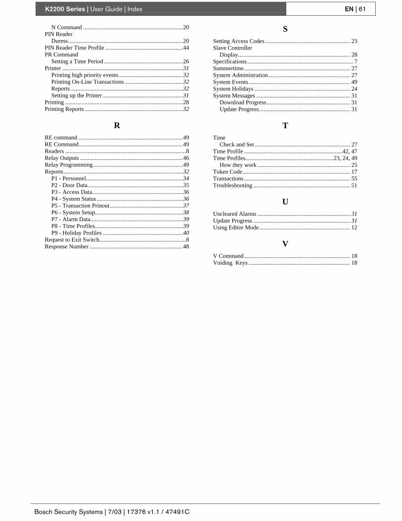
K2200 Series | User Guide | Index EN | 61
Bosch Security Systems | 7/03 | 17376 v1.1 / 47491C
N Command ...................................................................20PIN Reader
Duress.............................................................................20PIN Reader Time Profile ....................................................44PR Command
Setting a Time Period .....................................................26Printer .................................................................................31
Printing high priority events...........................................32Printing On-Line Transactions .......................................32Reports ...........................................................................32Setting up the Printer ......................................................31
Printing ...............................................................................28Printing Reports ..................................................................32
RRE command ......................................................................49RE Command......................................................................49Readers .................................................................................8Relay Outputs .....................................................................46Relay Programming ............................................................49Reports................................................................................32
P1 - Personnel.................................................................34P2 - Door Data................................................................35P3 - Access Data.............................................................36P4 - System Status..........................................................36P5 - Transaction Prinout.................................................37P6 - System Setup...........................................................38P7 - Alarm Data..............................................................39P8 - Time Profiles...........................................................39P9 - Holiday Profiles ......................................................40
Request to Exit Switch..........................................................8Response Number ...............................................................48
SSetting Access Codes ......................................................... 23Slave Controller
Display........................................................................... 28Specifications....................................................................... 7Summertime....................................................................... 27System Administration....................................................... 27System Events.................................................................... 49System Holidays ................................................................ 24System Messages ............................................................... 31
Download Progress........................................................ 31Update Progress............................................................. 31
TTime
Check and Set ................................................................ 27Time Profile ..................................................................42, 47Time Profiles...........................................................23, 24, 49
How they work .............................................................. 25Token Code........................................................................ 17Transactions ....................................................................... 55Troubleshooting ................................................................. 51
UUncleared Alarms .............................................................. 31Update Progress ................................................................. 31Using Editor Mode............................................................. 12
VV Command....................................................................... 18Voiding Keys .................................................................... 18

© 2003 Bosch Security Systems17376 v1.1 / 47491C
Bosch Security Systems130 Perinton ParkwayFairport, NY 14450-9199Customer Service: (800) 289-0096Technical Support: (888) 886-6189