4739a intrepid hc
TRANSCRIPT
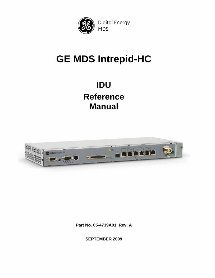
GE MDS Intrepid-HC
IDU
Reference Manual
Part No. 05-4739A01, Rev. A
SEPTEMBER 2009

Notice
This document contains information that is proprietary to GE MDS, LLC.
No part of this publication may be reproduced, modified, or distributed without prior written authorization of GE MDS, LLC. GE MDS reserves the right to correct any errors and omissions in this document without obligation to any party.
Registered Trademarks Other trade names referenced in this publication are owned by their respective holders.
Statement of Conditions
The information contained in this document is subject to change without notice.
GE MDS, LLC shall not be liable for errors contained herein or for incidental or consequential damage in connection with the furnishing, performance, or use of this document or equipment supplied with it.
Information to User
Any changes or modifications of equipment not expressly approved by the manufacturer could void the user’s authority to operate the equipment and the warranty for such equipment.
Copyright © 2009 by GE MDS, LLC. All rights reserved.
Corporate Headquarters: GE MDS, LLC 175 Science Parkway Rochester, NY USA Tel: 585-241-5510 Fax: 585-242-8369 Email: [email protected]
www.gemds.com
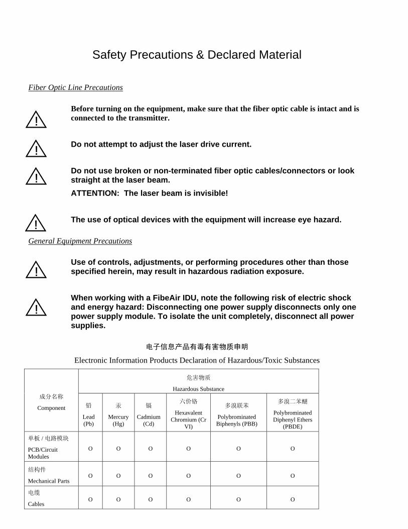
Safety Precautions & Declared Material
Fiber Optic Line Precautions
Before turning on the equipment, make sure that the fiber optic cable is intact and is connected to the transmitter.
Do not attempt to adjust the laser drive current.
Do not use broken or non-terminated fiber optic cables/connectors or look straight at the laser beam.
ATTENTION: The laser beam is invisible!
The use of optical devices with the equipment will increase eye hazard.
General Equipment Precautions
Use of controls, adjustments, or performing procedures other than those specified herein, may result in hazardous radiation exposure.
When working with a FibeAir IDU, note the following risk of electric shock and energy hazard: Disconnecting one power supply disconnects only one power supply module. To isolate the unit completely, disconnect all power supplies.
电子信息产品有毒有害物质申明
Electronic Information Products Declaration of Hazardous/Toxic Substances
危害物质
Hazardous Substance 成分名称
Component 铅
Lead (Pb)
汞
Mercury (Hg)
镉
Cadmium (Cd)
六价铬
Hexavalent Chromium (Cr
VI)
多溴联苯
Polybrominated Biphenyls (PBB)
多溴二苯醚
Polybrominated Diphenyl Ethers
(PBDE)
单板 / 电路模块
PCB/Circuit Modules
O O O O O O
结构件
Mechanical Parts O O O O O O
电缆
Cables O O O O O O
!!
!!
!!
!!
!!
!!


Contents
Chapter 1: Installation................................................................................... 1-1
General.................................................................................................................. 1-1
Site Requirements................................................................................................ 1-1
Pre-Installation ..................................................................................................... 1-1
Unpacking Equipment at the Site ....................................................................... 1-2
Installation Requirements ................................................................................... 1-2
FibeAir IP-10 Description .................................................................................... 1-4
Installing the IDU in a 19"/ETSI Rack ................................................................. 1-5
Grounding the IDU ............................................................................................... 1-7
Connecting the IDU.............................................................................................. 1-9
Configuring the IDU ........................................................................................... 1-10
Chapter 2: System Configurations............................................................... 2-1
General.................................................................................................................. 2-1
Ethernet-Only ....................................................................................................... 2-1
Ethernet + E1s/T1s............................................................................................... 2-2
Metro + E1/T1 Illustrations & Accessories ........................................................ 2-5
Metro 1+1 HSB, with E1s/T1s.............................................................................. 2-6
Metro 1+0, with E1s/T1s, 75 ohm........................................................................ 2-7
Metro 1+1 HSB, with E1s/T1s, 75 ohm ............................................................... 2-8
Chapter 3: Acceptance & Commissioning Procedures.............................. 3-1
General.................................................................................................................. 3-1
Site Acceptance Procedure................................................................................. 3-2
1+0 Commissioning Procedure .......................................................................... 3-7
1+1 Commissioning Procedure .......................................................................... 3-9
FibeAir IP-10 Commissioning Log.................................................................... 3-11
Appendix A: Line Interfaces .........................................................................A-1
Appendix B: Connector Pin-Outs.................................................................B-1
Appendix C: Protection Information ............................................................C-1

Appendix D: Accessories .............................................................................D-1
Appendix E: Fan Tray Replacement ............................................................E-1
Intrepid-HC Installation Guide 1-1
Chapter 1: Installation
General
This chapter provides instructions for the installation of the Intrepid-HC IDU at the customer site.
Note: For full functionality and feature availability, software upgrades are often available for GE MDS products. You can obtain the latest software version and release notes at the GE MDS website under the “Resources” tab at the top of the opening page.
Site Requirements
Unit must be located indoors.
The environment temperature must be between -5 C and +55 C.
Easily accessible, but only by authorized personnel.
Available power source of -48 VDC, and the site must comply with National Electric Code (NEC) standards.
Available management connection (Ethernet or dial-up).
No more than 300 meters from RFU location.
In addition, since the IDU will be connected to the RFU, when considering a site, it is important to check for current and future obstacles on the roof or tower. Possible future obstacles may include trees, new buildings, window cleaners on the roof, snow that may accumulate in front of the antenna, etc. The site should be accessible to certified personnel only.
Note about Heat Dissipation: The Intrepid-HC IDU overall heat dissipation is 25W max (~85 BTU/h).
Note about Antenna Location: As with any type of construction, a local permit may be required before installing an antenna. It is the owner’s responsibility to obtain any and all permits.
Pre-Installation
Packing
The equipment is packed at the factory, and sealed moisture-absorbing bags are inserted.
Intrepid-HC Installation Guide 1-2
Transportation
The equipment is prepared for public transportation. The cargo must be kept dry during transportation, in accordance with ETS 300 019-1-2, Class 2.3.
It is recommended to transport the equipment to the installation site in its original packing case.
If intermediate storage is required, the packed equipment must be stored in dry and cool conditions and out of direct sunlight, in accordance with ETS 300 019-1-1, Class 1.2.
Inspection
Check the packing lists, and ensure that the correct part numbers and quantities of components arrived.
Unpacking Equipment at the Site
A single system (1+0) is shipped in 5 crates. Upon delivery, make sure that the following items are included:
Two indoor units and accessories
Two outdoor units
For 13-38 GHz systems, verify that there is a high RFU and low RFU.
One CD with a management user guide.
Unpack the contents and check for damaged or missing parts. If any part is damaged or missing, contact your local distributor.
Installation Requirements
Required Tools
The following tools are required to install the IDU:
Philips screwdriver (for mounting the IDU to the rack and grounding screw)
Flathead small screwdriver (for PSU connector)
Wire Cutter/Stripper (or Sharp cutting knife)
Crimping tool for ground cable lug crimping (optional: if alternative grounding cable is used).
Intrepid-HC Installation Guide 1-3
Cables
In addition to the tools mentioned above, the interface connectors and their pin-outs, can be found in the following sections in this guide:
Appendix A: Line Interfaces
Appendix B: Connector Pin-Outs
Requirements for North America
Restricted Access Area: DC powered equipment should only be installed in a Restricted Access Area.
Installation Codes: The equipment must be installed according to country national electrical codes. For North America, equipment must be installed in accordance to the US National Electrical Code, Articles 110-16, 110-17 and 110-18, and the Canadian Electrical Code, Section 12.
Overcurrent Protection: A readily accessible Listed branch circuit overcurrent protective device, rated 15 A, must be incorporated in the building wiring.
CAUTION: This equipment is designed to permit connection between the grounded (earthed) conductor of the DC supply circuit and the grounding conductor at the equipment.
Grounded Supply System: The equipment shall be connected to a properly grounded supply system. All equipment in the immediate vicinity shall be grounded the same way, and shall not be grounded elsewhere.
Local Supply System: The DC supply system is to be local, i.e. within the same premises as the equipment.
Disconnect Device: A disconnect device is not allowed in the grounded circuit between the DC supply source and the frame/grounded circuit connection.
Intrepid-HC Description
Intrepid-HC is A GE MDS comprehensive high capacity migration-to-IP network solution. It is designed as a native Ethernet microwave radio platform that can integrate smoothly in any network, while providing a broad range of software-configurable licensed channel schemes.
Intrepid-HC follows in the tradition of GE MDS Native2, which allows your network to benefit from both native TDM and native Ethernet using the same radio. Flexible bandwidth sharing between the TDM and Ethernet traffic ensures optimal throughput for all your media transfer needs.
Intrepid-HC features a flexible design capable of addressing all network migration scenarios. With its Native2 capability for optimal traffic delivery, and modular architecture for all sites (Tail, Chain, Agg3, Agg2), this state-of-the-art radio platform offers the best approach to IP migration for advanced networks.
Intrepid-HC Installation Guide 1-4
With the widest capacity range (10-500 Mbps) for all capacity needs, advanced Adaptive Code Modulation for the best spectrum utilization, and a scalable system that ensures future-proof network expansion, Intrepid-HC is the ideal solution for risk-free migration.
Some of the important points that place Intrepid-HC at the top of the wireless IP market include:
Supports all licensed bands, from 6 to 38 GHz
Supports channel bandwidths of from 7 MHz to 56 MHz
Supports throughputs of from 10 to 500 Mbps per radio carrier (QPSK to 256 QAM)
Incorporates advanced integrated Ethernet switching capabilities
In addition, using unique Adaptive Code & Modulation (ACM), your network benefits from non-stop, dependable capacity delivery.
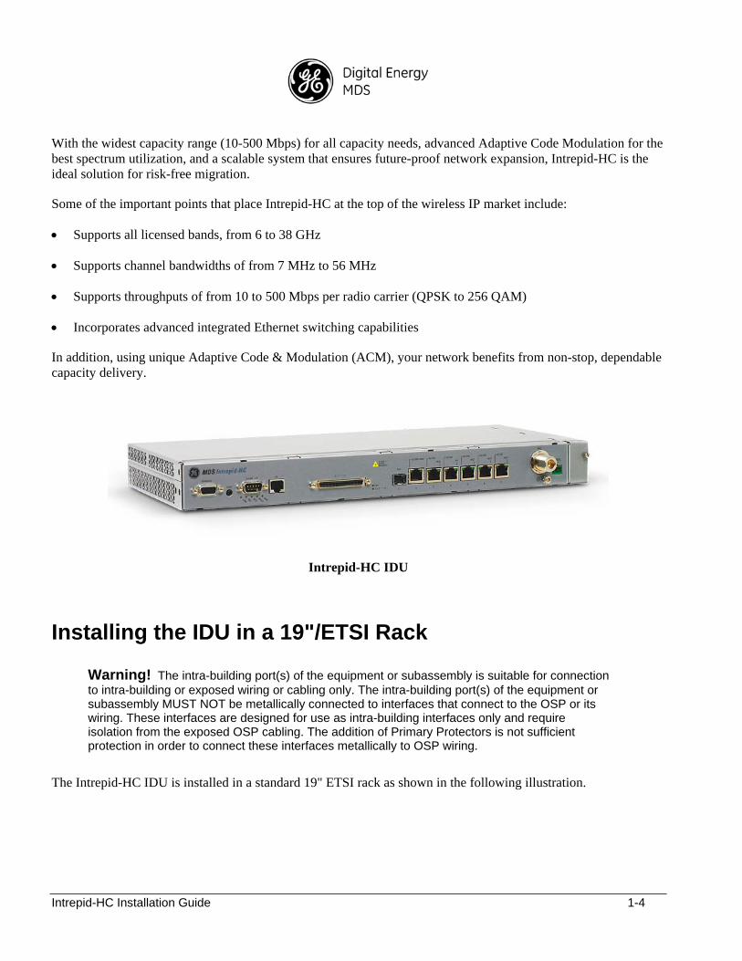
Intrepid-HC IDU
Installing the IDU in a 19"/ETSI Rack
Warning! The intra-building port(s) of the equipment or subassembly is suitable for connection to intra-building or exposed wiring or cabling only. The intra-building port(s) of the equipment or subassembly MUST NOT be metallically connected to interfaces that connect to the OSP or its wiring. These interfaces are designed for use as intra-building interfaces only and require isolation from the exposed OSP cabling. The addition of Primary Protectors is not sufficient protection in order to connect these interfaces metallically to OSP wiring.
The Intrepid-HC IDU is installed in a standard 19" ETSI rack as shown in the following illustration.

Intrepid-HC Installation Guide 1-5
As shown in the illustration, four screws, supplied with the installation kit, are used to secure the IDU to the rack.
Intrepid-HC Installation Guide 1-6
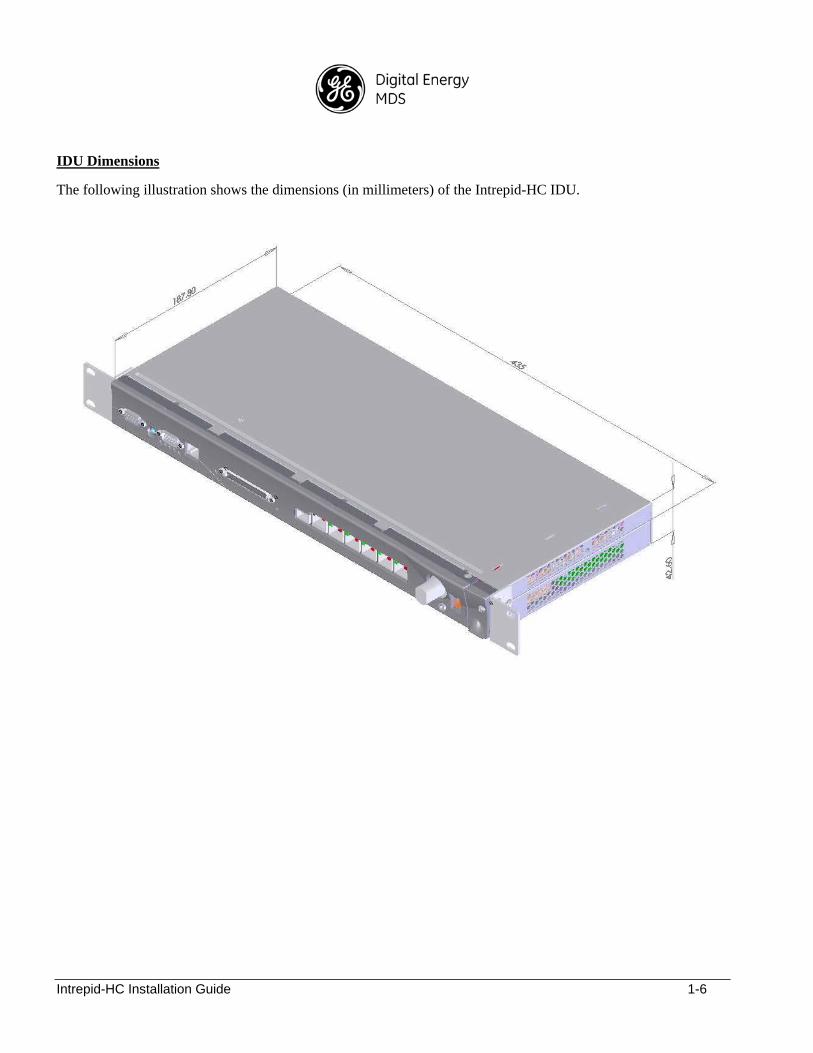
IDU Dimensions
The following illustration shows the dimensions (in millimeters) of the Intrepid-HC IDU.
Intrepid-HC Installation Guide 1-7
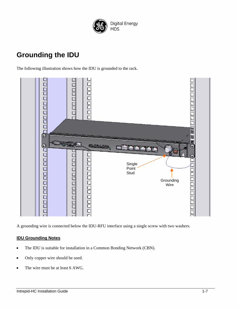
Grounding the IDU
The following illustration shows how the IDU is grounded to the rack.
A grounding wire is connected below the IDU-RFU interface using a single screw with two washers.
IDU Grounding Notes
The IDU is suitable for installation in a Common Bonding Network (CBN).
Only copper wire should be used.
The wire must be at least 6 AWG.
Single Point Stud
Grounding Wire
Intrepid-HC Installation Guide 1-8
Connector and connection surfaces must be plated. Bare conductors must be coated with antioxidant before crimp connections are made to the screws.
The unit provides a ground for each IDU, via a one-hole mounted lug onto a single-point stud. The stud must be installed using a UL-listed ring tongue terminal, and two star washers for anti-rotation.
For antenna ports, lightning protection is used that does not permit transients of a greater magnitude than the following:
Open Circuit: 1.2-50us 600V
Short Circuit: 8-20us 300A
The current carrying “ampacity” of the conductor connecting the IDU frame to the DC return conductor is equal to, or greater than, the ampacity of the associated DC return conductor.
Power Supply Notes
When selecting a power source, the following must be considered:
DC power can be from -40.5 VDC to -60 VDC.
Recommended: Availability of a UPS (Uninterrupted Power Source), battery backup, and emergency power generator.
Whether or not the power source provides constant power (i.e., power is secured on weekends or is shut off frequently and consistently).
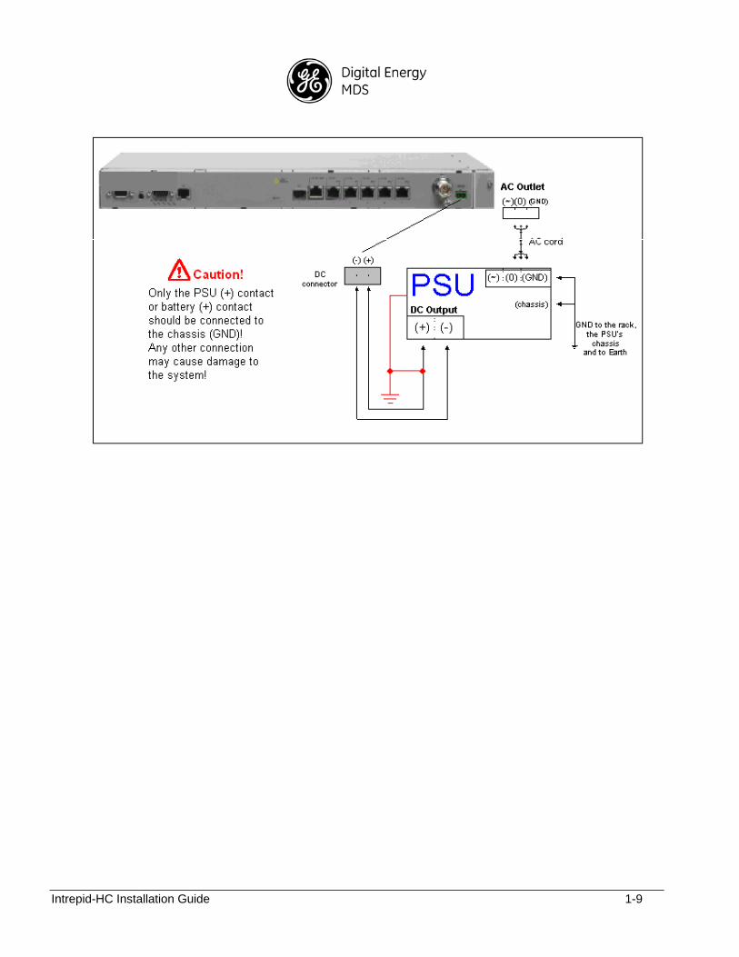
The power supply must have grounding points on the AC and DC sides.
Caution!
The user power supply GND must be connected to the positive pole in the IDU power supply. Any other connection may cause damage to the system!
Power supply grounding should be in accordance with the following illustration:
Intrepid-HC Installation Guide 1-9
Intrepid-HC Installation Guide 1-10
Connecting the IDU
This section describes how the IDU interfaces are connected for a 1+0 system. The interfaces include line, system (IDU-RFU), and management ports.
For interface specifications, see Appendix A - Line Interfaces and Cables.
For connector pin-outs, see Appendix B - Connector Pin-Outs.
For a list of accessories, see Appendix D - Accessories.
Note: For a 1+1 system, a protection panel is used, as described in Appendix C - Protection Information.
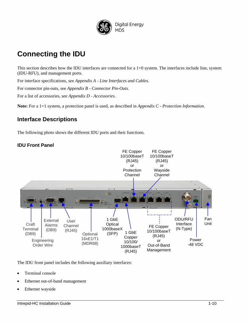
Interface Descriptions
The following photo shows the different IDU ports and their functions.
IDU Front Panel
The IDU front panel includes the following auxiliary interfaces:
Terminal console
Ethernet out-of-band management
Ethernet wayside
Craft Terminal
(DB9)
Engineering Order Wire
External Alarms (DB9)
Optional 16xE1/T1 (MDR68)
User Channel (RJ45)
1 GbE Optical
1000baseX (SFP) 1 GbE
Copper 10/100/
1000baseT(RJ45)
FE Copper 10/100baseT
(RJ45) or
Protection Channel
ODU/RFU Interface (N-Type)
Power -48 VDC
FE Copper 10/100baseT
(RJ45) or
Wayside Channel
FE Copper 10/100baseT
(RJ45) or
Out-of-Band Management
FanUnit
Intrepid-HC Installation Guide 1-11
Optional:
Engineering Order Wire (EOW)
User channel (V11, RS232)
External alarms
Note: The Fast Ethernet interface channels can be logically configured for either Fast Ethernet traffic, or protection, wayside, or management traffic.
IDU-ODU/RFU Coax Cable
The Coax Cable that connects between the IDU and the ODU/RFU should be terminated with N-type male connectors.
Important! Make sure that the inner pin of the connector does not exceed the edge of the connector.
The cable should have a maximum attenuation of 30 dB at 350 MHz.
Configuring the IDU
After the system is installed and tested, and antenna alignment is performed, the next step is IDU setup and configuration.
Setup procedures are performed using the Intrepid-HC CLI (Command Line Interface) or Web Based Management.
For an explanation of the CLI, see the Intrepid-HC CLI Guide.
For an explanation of the Web Based Management, see the Intrepid-HC Web Based Management Guide.

Intrepid-HC Installation Guide 1-12
Intrepid-HC Installation Guide 2-1
Chapter 2: System Configurations
General
This chapter describes basic configurations and their required accessories.
The unit operates as an Ethernet-Only or Ethernet + E1/T1 system.
Ethernet-Only
Note: Ethernet only configurations use Y and H cable splitters.
Examples
The following are examples of Ethernet-Only configurations:
Tail/PtP
1+0 (1 unit)
1+1 (2 units + 1 protection panel)
Chain node with local traffic
1+0:1+0 (2 units)
1+0:1+1 (3 units + 1 protection panel)
1+1:1+1 (4 units + 2 protection panels)
Aggregation node
4 x 1+0 : 1+1 (6 units + 1 protection panel)
2 x 1+1 : 1+1 (6 units + 3 protection panels)
Additional Features/Components
The following features and components can be included with the configurations listed above:
- Optical GbE (SFP)
- Switch/pipe mode (license-specific)
- External switch (for aggregation node only)
- Auxiliary interfaces (EOW, alarms, user channel)
Intrepid-HC Installation Guide 2-2
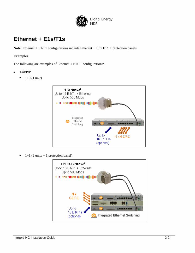
Ethernet + E1s/T1s
Note: Ethernet + E1/T1 configurations include Ethernet + 16 x E1/T1 protection panels.
Examples
The following are examples of Ethernet + E1/T1 configurations:
Tail/PtP
1+0 (1 unit)
1+1 (2 units + 1 protection panel)
Integrated Ethernet SwitchingIntegrated Ethernet Switching
Intrepid-HC Installation Guide 2-3
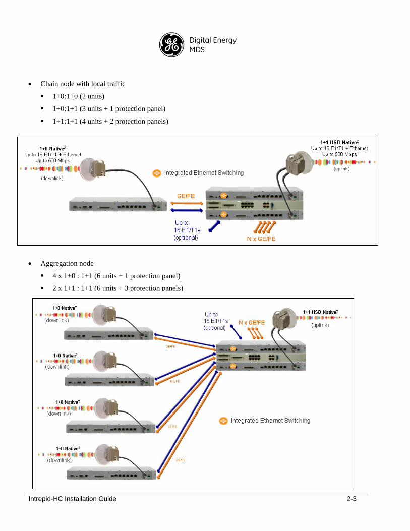
Chain node with local traffic
1+0:1+0 (2 units)
1+0:1+1 (3 units + 1 protection panel)
1+1:1+1 (4 units + 2 protection panels)
Aggregation node
4 x 1+0 : 1+1 (6 units + 1 protection panel)
2 x 1+1 : 1+1 (6 units + 3 protection panels)
Intrepid-HC Installation Guide 2-4
Additional Features/Components
The following features and components can be included with the configurations listed above:
- Optical GbE (SFP)
- Switch/pipe mode
- External switch (for aggregation node only)
- Auxiliary interfaces (EOW, alarms, user channel)
- T1s/E1s (120 ohm/75 ohm)
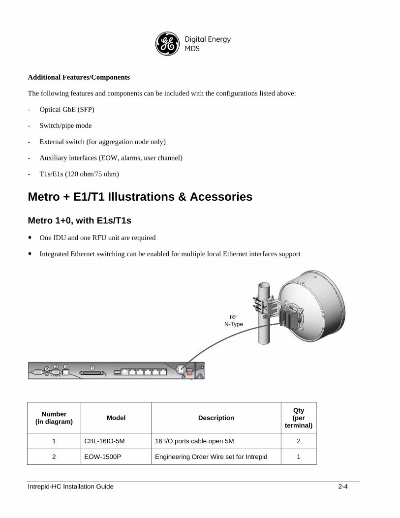
Metro + E1/T1 Illustrations & Acessories
Metro 1+0, with E1s/T1s
One IDU and one RFU unit are required
Integrated Ethernet switching can be enabled for multiple local Ethernet interfaces support
Number (in diagram)
Model Description Qty (per
terminal)
1 CBL-16IO-5M 16 I/O ports cable open 5M 2
2 EOW-1500P Engineering Order Wire set for Intrepid 1
Intrepid-HC Installation Guide 2-5
3 IDU-EXT-ALARMS-CBL-2.5m
IDU external alarms open cable 2.5m 1
4 IDU-UC-CBL-2m User channel cable 2m D-type 9-pin male 1
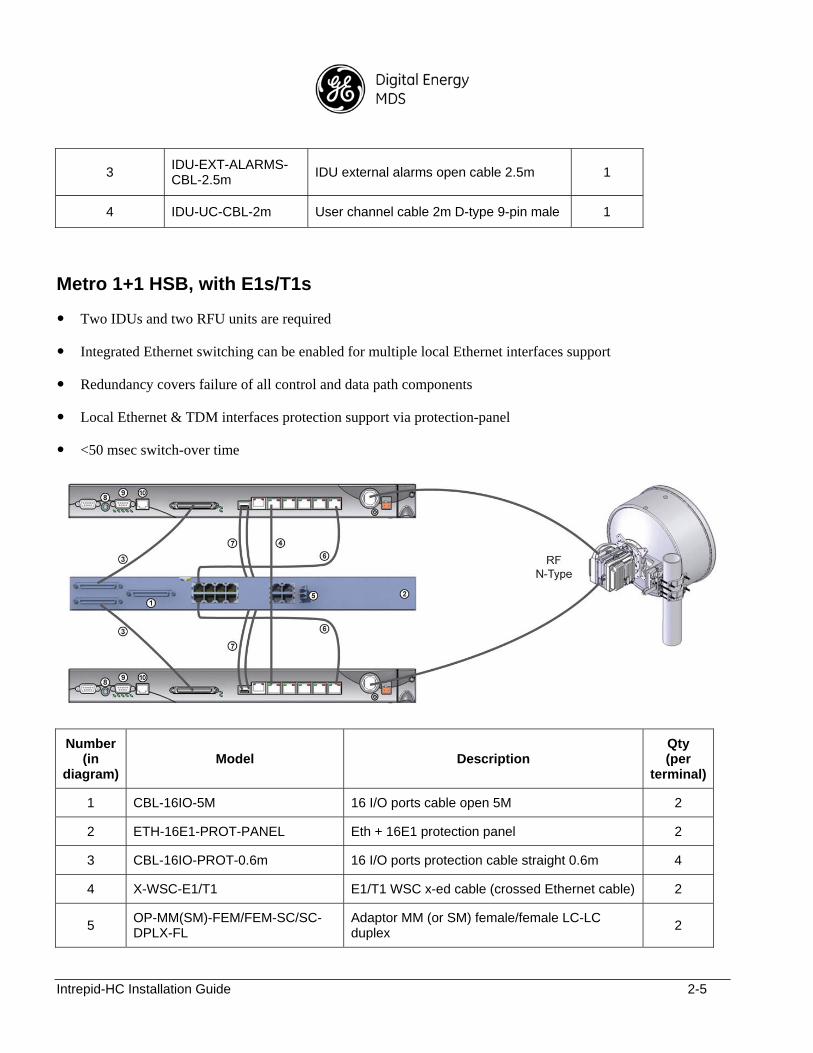
Metro 1+1 HSB, with E1s/T1s
Two IDUs and two RFU units are required
Integrated Ethernet switching can be enabled for multiple local Ethernet interfaces support
Redundancy covers failure of all control and data path components
Local Ethernet & TDM interfaces protection support via protection-panel
<50 msec switch-over time
Number (in
diagram) Model Description
Qty (per
terminal)
1 CBL-16IO-5M 16 I/O ports cable open 5M 2
2 ETH-16E1-PROT-PANEL Eth + 16E1 protection panel 2
3 CBL-16IO-PROT-0.6m 16 I/O ports protection cable straight 0.6m 4
4 X-WSC-E1/T1 E1/T1 WSC x-ed cable (crossed Ethernet cable) 2
5 OP-MM(SM)-FEM/FEM-SC/SC- DPLX-FL
Adaptor MM (or SM) female/female LC-LC duplex
2
Intrepid-HC Installation Guide 2-6
6 CBL-FE-0.5M FE protection cable straight 0.5m 8
7 GBE-SPL-MM(SM) Optical splitter MM (or SM) 4
8 EOW-1500P Engineering Order Wire set for Intrepid products 2
9 IDU-EXT-ALARMS-CBL-2.5m-PROT
External alarms cable 2.5m, with protection 2
10 IDU-UC-CBL-2m User channel cable 2m D-type 9-pin male 2
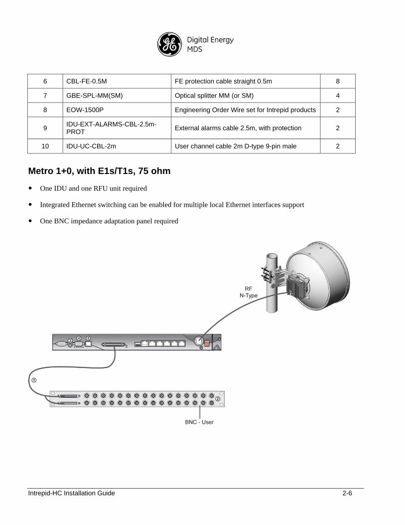
Metro 1+0, with E1s/T1s, 75 ohm
One IDU and one RFU unit required
Integrated Ethernet switching can be enabled for multiple local Ethernet interfaces support
One BNC impedance adaptation panel required

Intrepid-HC Installation Guide 2-7
Number (in
diagram) Model Description
Qty (per
terminal)
1 CBL-16E1-CB-120-75 16E1 cable MDR to 2xDB44 5m 2
2 CB 120-75-BNC-GEN Impedance adaptation panel BNC - generic 2
3 EOW-1500P Engineering Order Wire set for Intrepid products
1
4 IDU-EXT-ALARMS-CBL-2.5m
IDU external alarms open cable 2.5m 1
5 IDU-UC-CBL-2m User channel cable 2m D-type 9-pin male 1
Metro 1+1 HSB, with E1s/T1s, 75 ohm
Two IDUs and two RFU units are required
Integrated Ethernet switching can be enabled for multiple local Ethernet interfaces support
Redundancy covers failure of all control and data path components
Local Ethernet & TDM interfaces protection support via protection-panel
<50 msec switch-over time
One BNC impedance adaptation panel required

Intrepid-HC Installation Guide 2-8
Number (in
diagram) Model Description
Qty (per
terminal)
1 CBL-16E1-CB-120-75 16E1 cable MDR to 2xDB44 5m 2
2 CB 120-75-BNC-GEN Impedance adaptation panel BNC - generic 2
3 ETH-16E1-PROT-PANEL Eth + 16E1 protection panel 2
4 CBL-16IO-PROT-0.6m 16 I/O ports protection cable straight 0.6m 4
5 X-WSC-E1/T1 E1/T1 WSC x-ed cable (crossed Ethernet cable) 2
6 OP-MM(SM)-FEM/FEM-SC/SC-DPLX-FL
Adaptor MM/SM female/female LC-LC duplex 2
7 CBL-FE-0.5M FE Prot cable straight 0.5m 8
8 GBE-SPL-MM(SM) Optical splitter MM (or SM) 4
9 EOW-1500P Engineering Order Wire set for Intrepid products 2
10 IDU-EXT-ALARMS-CBL-2.5m-PROT
External alarms cable 2.5m, with protection 2
11 IDU-UC-CBL-2m User channel cable 2m D-type 9-pin male 2

Intrepid-HC Installation Guide 3-1
Chapter 3: Acceptance & Commissioning Procedures
General
This chapter provides recommended Acceptance and Commissioning Procedure for the Intrepid-HC. Acceptance and commissioning should be performed after initial setup is complete.
The purpose of this procedure is to verify correct installation and operation of the installed link and the interoperability with customer end equipment.
Acceptance and Commissioning procedure includes the following stages:
Site Acceptance Procedure
Commissioning of radio link in a 1+0 configuration
Commissioning of radio link in a 1+1 configuration
The Site Acceptance Procedure is a checklist that summarizes the installation requirements of the site at which the products were installed.
The commissioning tests cover the required configuration information that should be recorded, and the tests that should be performed on the radio link in 1+0 and 1+1 configurations.
Site Acceptance Procedure
The purpose of the following procedures is to verify that all installation requirements were noted and checked. Following this procedure will ensure proper, long-lasting, and safe operation of the product.
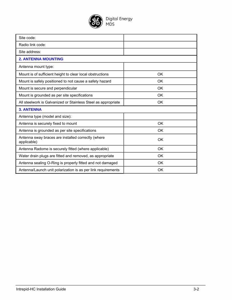
The checklist below summarizes the installation requirements of the site.
SITE ACCEPTANCE CHECKLIST
1. SITE INFORMATION
Customer:
Radio model:
Site name:
Intrepid-HC Installation Guide 3-2
Site code:
Radio link code:
Site address:
2. ANTENNA MOUNTING
Antenna mount type:
Mount is of sufficient height to clear local obstructions OK
Mount is safely positioned to not cause a safety hazard OK
Mount is secure and perpendicular OK
Mount is grounded as per site specifications OK
All steelwork is Galvanized or Stainless Steel as appropriate OK
3. ANTENNA
Antenna type (model and size):
Antenna is securely fixed to mount OK
Antenna is grounded as per site specifications OK
Antenna sway braces are installed correctly (where applicable)
OK
Antenna Radome is securely fitted (where applicable) OK
Water drain plugs are fitted and removed, as appropriate OK
Antenna sealing O-Ring is properly fitted and not damaged OK
Antenna/Launch unit polarization is as per link requirements OK
Intrepid-HC Installation Guide 3-3
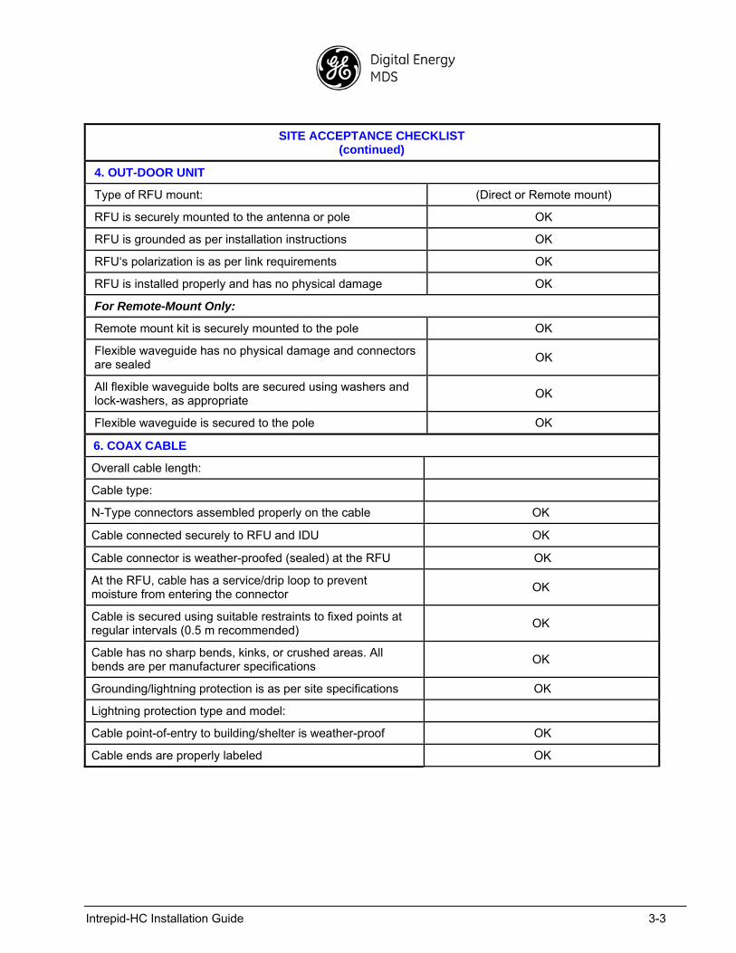
SITE ACCEPTANCE CHECKLIST (continued)
4. OUT-DOOR UNIT
Type of RFU mount: (Direct or Remote mount)
RFU is securely mounted to the antenna or pole OK
RFU is grounded as per installation instructions OK
RFU‘s polarization is as per link requirements OK
RFU is installed properly and has no physical damage OK
For Remote-Mount Only:
Remote mount kit is securely mounted to the pole OK
Flexible waveguide has no physical damage and connectors are sealed
OK
All flexible waveguide bolts are secured using washers and lock-washers, as appropriate
OK
Flexible waveguide is secured to the pole OK
6. COAX CABLE
Overall cable length:
Cable type:
N-Type connectors assembled properly on the cable OK
Cable connected securely to RFU and IDU OK
Cable connector is weather-proofed (sealed) at the RFU OK
At the RFU, cable has a service/drip loop to prevent moisture from entering the connector
OK
Cable is secured using suitable restraints to fixed points at regular intervals (0.5 m recommended)
OK
Cable has no sharp bends, kinks, or crushed areas. All bends are per manufacturer specifications
OK
Grounding/lightning protection is as per site specifications OK
Lightning protection type and model:
Cable point-of-entry to building/shelter is weather-proof OK
Cable ends are properly labeled OK
Intrepid-HC Installation Guide 3-4
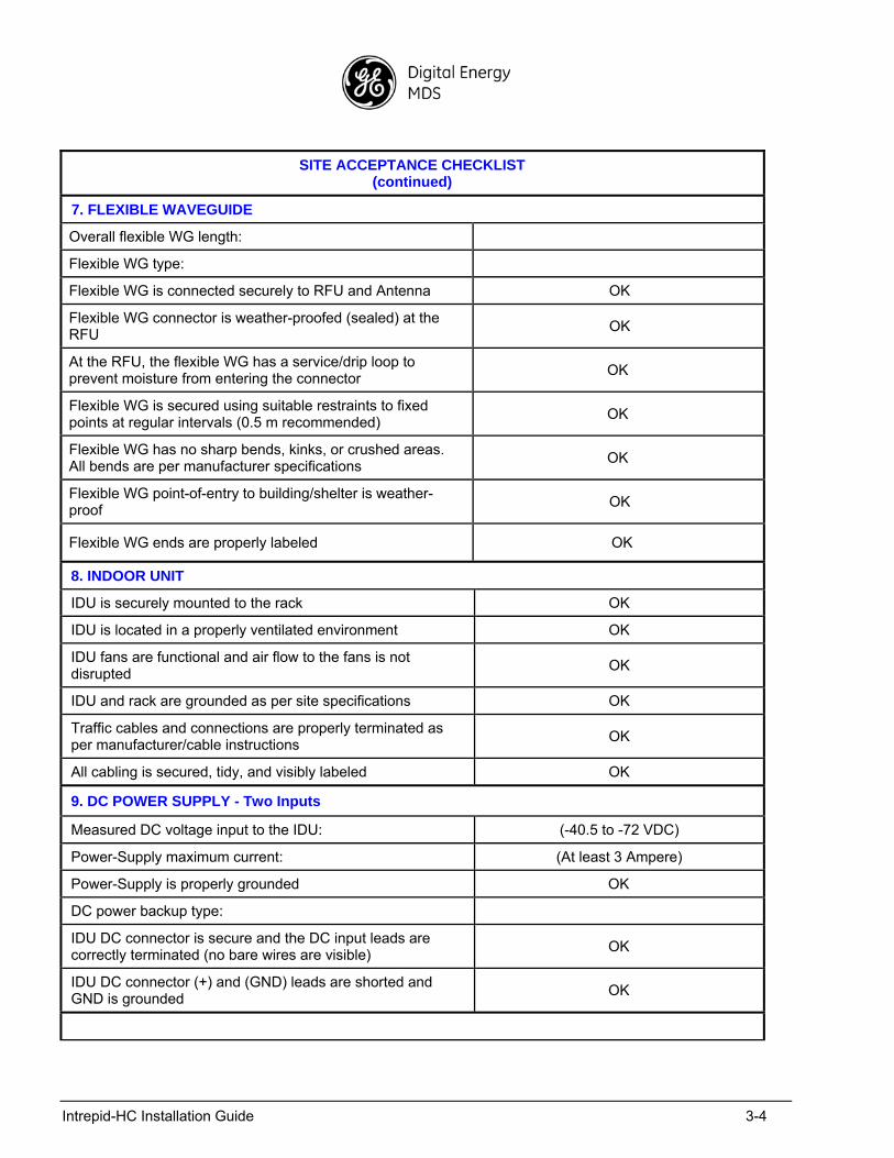
SITE ACCEPTANCE CHECKLIST (continued)
7. FLEXIBLE WAVEGUIDE
Overall flexible WG length:
Flexible WG type:
Flexible WG is connected securely to RFU and Antenna OK
Flexible WG connector is weather-proofed (sealed) at the RFU
OK
At the RFU, the flexible WG has a service/drip loop to prevent moisture from entering the connector
OK
Flexible WG is secured using suitable restraints to fixed points at regular intervals (0.5 m recommended)
OK
Flexible WG has no sharp bends, kinks, or crushed areas. All bends are per manufacturer specifications
OK
Flexible WG point-of-entry to building/shelter is weather-proof
OK
Flexible WG ends are properly labeled OK
8. INDOOR UNIT
IDU is securely mounted to the rack OK
IDU is located in a properly ventilated environment OK
IDU fans are functional and air flow to the fans is not disrupted
OK
IDU and rack are grounded as per site specifications OK
Traffic cables and connections are properly terminated as per manufacturer/cable instructions
OK
All cabling is secured, tidy, and visibly labeled OK
9. DC POWER SUPPLY - Two Inputs
Measured DC voltage input to the IDU: (-40.5 to -72 VDC)
Power-Supply maximum current: (At least 3 Ampere)
Power-Supply is properly grounded OK
DC power backup type:
IDU DC connector is secure and the DC input leads are correctly terminated (no bare wires are visible)
OK
IDU DC connector (+) and (GND) leads are shorted and GND is grounded
OK
Intrepid-HC Installation Guide 3-5
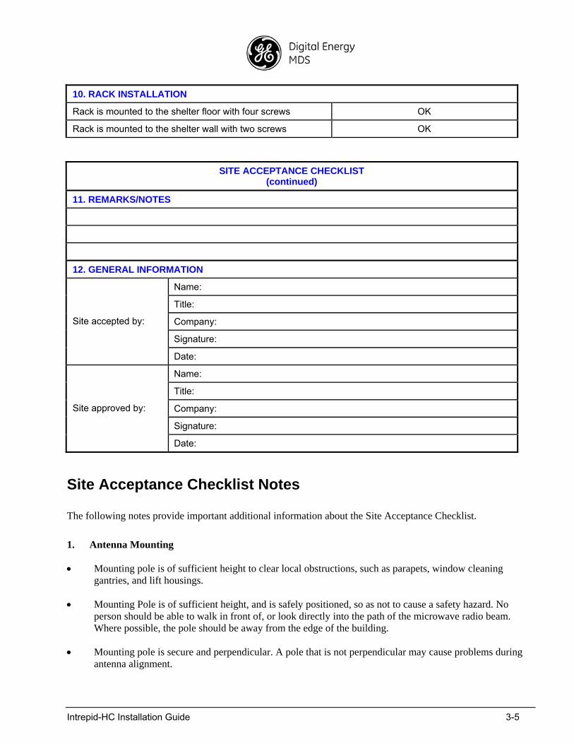
10. RACK INSTALLATION
Rack is mounted to the shelter floor with four screws OK
Rack is mounted to the shelter wall with two screws OK
SITE ACCEPTANCE CHECKLIST (continued)
11. REMARKS/NOTES
12. GENERAL INFORMATION
Name:
Title:
Company:
Signature:
Site accepted by:
Date:
Name:
Title:
Company:
Signature:
Site approved by:
Date:
Site Acceptance Checklist Notes
The following notes provide important additional information about the Site Acceptance Checklist.
1. Antenna Mounting
Mounting pole is of sufficient height to clear local obstructions, such as parapets, window cleaning gantries, and lift housings.
Mounting Pole is of sufficient height, and is safely positioned, so as not to cause a safety hazard. No person should be able to walk in front of, or look directly into the path of the microwave radio beam. Where possible, the pole should be away from the edge of the building.
Mounting pole is secure and perpendicular. A pole that is not perpendicular may cause problems during antenna alignment.

Intrepid-HC Installation Guide 3-6
Mounting pole is grounded as per site specifications. All operators and site owners have specific requirements regarding the grounding of installations. As a minimum, typical requirements are such that any metal structure must be connected to the existing lightning protection ground of the building. Where it extends beyond the 45-degree cone of protection of existing lightning conductors, additional lightning protectors should be installed.
All steelwork is Galvanized or Stainless Steel, as appropriate to prevent corrosion.
2. Antenna
Antenna is grounded as per site specifications. See the third point in the Antenna Mounting section above.
Antenna sway braces are fitted and installed correctly, where applicable. Typically, for an antenna of 1.2 m or larger, an extra sway brace is fitted to the mounting frame of the antenna. This sway brace should not be mounted to the same pole as the antenna, but should be installed directly back to the tower or an alternative point.
Antenna Water Drain Plugs are fitted and removed, where appropriate. Some antennas have moisture drain plugs installed at various points around the antenna. The purpose of these plugs is to allow any moisture that forms on the inside of the antenna or radome to drip out and prevent a pool within the antenna. Only the plugs at the bottom of the antenna, after installation, should be removed. All other plugs should be left in position.
3. RFU (Radio Frequency Unit)
The RFU is grounded as per installation instructions. See the third point in the Antenna Mounting section above.
The RFU polarization is as per link requirements and matches the polarization of the antenna.
4. IDU (Indoor Unit)
The main traffic connections are correctly terminated and crimped as per cable and connector manufacturer instructions. All fiber optic patch leads should be routed carefully and efficiently, using conduits to prevent damage to the cables.
All other user terminations are secure and correctly terminated.
All labeling is complete as per site requirements. Labeling is specific to each customer. At a site with only one installation, labeling may be unnecessary. However, at sites with multiple installations, correct and adequate labeling is essential for future maintenance operations.
Typical labeling requirements include:
Antenna labels - for link identity and bearing
RFU labels - for link identity, frequency, and polarization
Coax cable labels - for link identity, close to the RFU, IDU, and either end of any joint
IDU labels - for link identity
Intrepid-HC Installation Guide 3-7
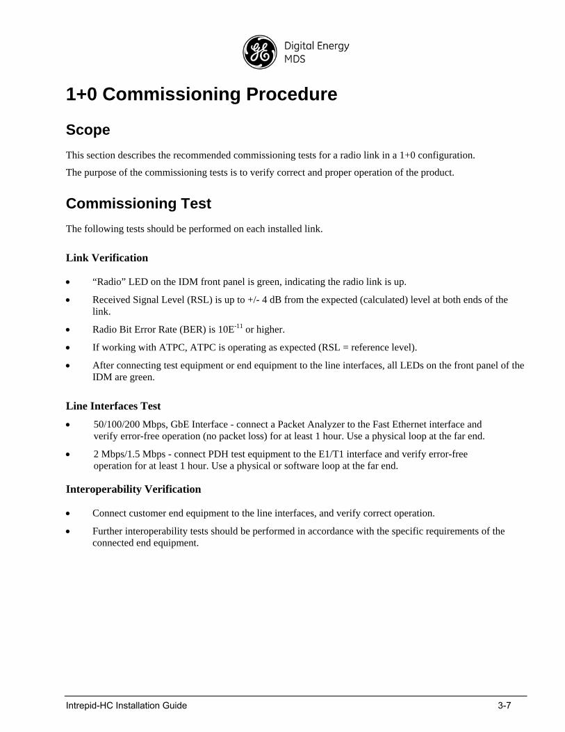
1+0 Commissioning Procedure
Scope
This section describes the recommended commissioning tests for a radio link in a 1+0 configuration.
The purpose of the commissioning tests is to verify correct and proper operation of the product.
Commissioning Test
The following tests should be performed on each installed link.
Link Verification
“Radio” LED on the IDM front panel is green, indicating the radio link is up.
Received Signal Level (RSL) is up to +/- 4 dB from the expected (calculated) level at both ends of the link.
Radio Bit Error Rate (BER) is 10E-11 or higher.
If working with ATPC, ATPC is operating as expected (RSL = reference level).
After connecting test equipment or end equipment to the line interfaces, all LEDs on the front panel of the IDM are green.
Line Interfaces Test
50/100/200 Mbps, GbE Interface - connect a Packet Analyzer to the Fast Ethernet interface and verify error-free operation (no packet loss) for at least 1 hour. Use a physical loop at the far end.
2 Mbps/1.5 Mbps - connect PDH test equipment to the E1/T1 interface and verify error-free operation for at least 1 hour. Use a physical or software loop at the far end.
Interoperability Verification
Connect customer end equipment to the line interfaces, and verify correct operation.
Further interoperability tests should be performed in accordance with the specific requirements of the connected end equipment.
Intrepid-HC Installation Guide 3-8
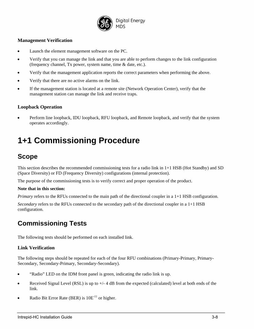
Management Verification
Launch the element management software on the PC.
Verify that you can manage the link and that you are able to perform changes to the link configuration (frequency channel, Tx power, system name, time & date, etc.).
Verify that the management application reports the correct parameters when performing the above.
Verify that there are no active alarms on the link.
If the management station is located at a remote site (Network Operation Center), verify that the management station can manage the link and receive traps.
Loopback Operation
Perform line loopback, IDU loopback, RFU loopback, and Remote loopback, and verify that the system operates accordingly.
1+1 Commissioning Procedure
Scope
This section describes the recommended commissioning tests for a radio link in 1+1 HSB (Hot Standby) and SD (Space Diversity) or FD (Frequency Diversity) configurations (internal protection).
The purpose of the commissioning tests is to verify correct and proper operation of the product.
Note that in this section:
Primary refers to the RFUs connected to the main path of the directional coupler in a 1+1 HSB configuration.
Secondary refers to the RFUs connected to the secondary path of the directional coupler in a 1+1 HSB configuration.
Commissioning Tests
The following tests should be performed on each installed link.
Link Verification
The following steps should be repeated for each of the four RFU combinations (Primary-Primary, Primary-Secondary, Secondary-Primary, Secondary-Secondary).
“Radio” LED on the IDM front panel is green, indicating the radio link is up.
Received Signal Level (RSL) is up to +/- 4 dB from the expected (calculated) level at both ends of the link.
Radio Bit Error Rate (BER) is 10E-11 or higher.
Intrepid-HC Installation Guide 3-9
If working with ATPC, ATPC is operating as expected (RSL = reference level).
After connecting test equipment or end equipment to the line interfaces, all LEDs on the front panel of the IDM are green.
Line Interfaces Test
50/100/200 Mbps, GbE interface - connect a Packet Analyzer to the Fast Ethernet interfaces using an FE splitter, and verify error-free operation (no packet loss) for at least 1 hour. Use a physical loop at the far end.
2 Mbps/1.5 Mbps - connect PDH test equipment to the E1/T1 interfaces using splitters, and verify error-free operation for at least 1 hour. Use a physical loop between the splitters at the far end.
Switching Tests
Define each of the N channels as preferred (one at a time) for errorless switching to the +1 channel. The regular channel supports hitless switching to the +1 channel.
50/100/200 Mbps, GbE Interface
Connect a Packet Analyzer to the Fast Ethernet interfaces using splitters. Use a physical loop between the splitters at the far end. Verify no alarms exist.
Perform the following switching tests from one IDM to the other, and verify the system switches automatically.
- Power: power off the active IDM
- Radio: disconnect the coax cable of the active IDM
- Management: force a switch using the management software
1.5/2 Mbps Interface
Connect PDH test equipment to the interfaces using splitters. Use a physical loop between the splitters at the far end. Verify no alarms exist.
Perform the following switching tests from one IDM to the other, and verify the system switches automatically.
- Power: power off the active IDM
- Radio: disconnect the coax cable of the active IDM
- Management: force a switch using the management application
Interoperability Verification
Connect the customer end equipment to the line interfaces and verify correct operation.
Further interoperability tests should be performed in accordance with the specific requirements of the connected end equipment.
Intrepid-HC Installation Guide 3-10
Management Verification
Launch the management application.
Verify that you can manage the link and that you are able to perform changes to the link configuration (frequency channel, TX power, system name, time & date, etc.).
Verify that the application reports the correct parameters when performing the above.
Verify that there are no active alarms on the link.
If the management station is located a t a remote site (Network Operation Center), verify that the management station can manage the link and receive traps.
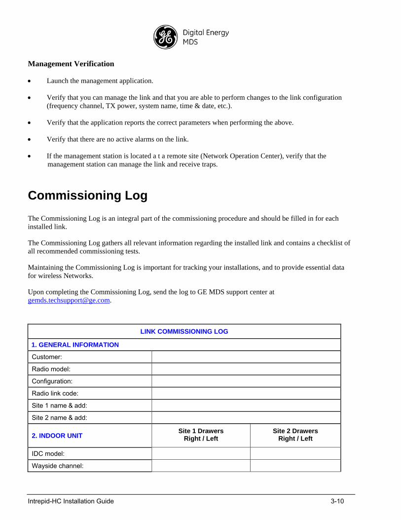
Commissioning Log
The Commissioning Log is an integral part of the commissioning procedure and should be filled in for each installed link.
The Commissioning Log gathers all relevant information regarding the installed link and contains a checklist of all recommended commissioning tests.
Maintaining the Commissioning Log is important for tracking your installations, and to provide essential data for wireless Networks.
Upon completing the Commissioning Log, send the log to GE MDS support center at [email protected].
LINK COMMISSIONING LOG
1. GENERAL INFORMATION
Customer:
Radio model:
Configuration:
Radio link code:
Site 1 name & add:
Site 2 name & add:
2. INDOOR UNIT Site 1 Drawers
Right / Left Site 2 Drawers
Right / Left
IDC model:
Wayside channel:
Intrepid-HC Installation Guide 3-11
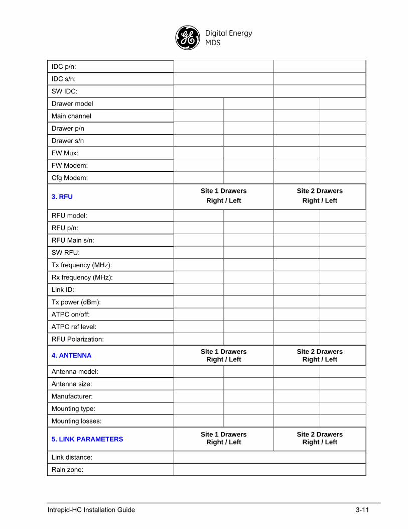
IDC p/n:
IDC s/n:
SW IDC:
Drawer model
Main channel
Drawer p/n
Drawer s/n
FW Mux:
FW Modem:
Cfg Modem:
3. RFU Site 1 Drawers
Right / Left
Site 2 Drawers
Right / Left
RFU model:
RFU p/n:
RFU Main s/n:
SW RFU:
Tx frequency (MHz):
Rx frequency (MHz):
Link ID:
Tx power (dBm):
ATPC on/off:
ATPC ref level:
RFU Polarization:
4. ANTENNA Site 1 Drawers
Right / Left Site 2 Drawers
Right / Left
Antenna model:
Antenna size:
Manufacturer:
Mounting type:
Mounting losses:
5. LINK PARAMETERS Site 1 Drawers
Right / Left Site 2 Drawers
Right / Left
Link distance:
Rain zone:
Intrepid-HC Installation Guide 3-12
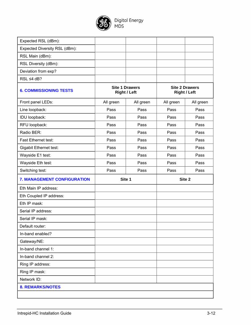
Expected RSL (dBm):
Expected Diversity RSL (dBm):
RSL Main (dBm):
RSL Diversity (dBm):
Deviation from exp?
RSL ≤4 dB?
6. COMMISSIONING TESTS Site 1 Drawers
Right / Left Site 2 Drawers
Right / Left
Front panel LEDs: All green All green All green All green
Line loopback: Pass Pass Pass Pass
IDU loopback: Pass Pass Pass Pass
RFU loopback: Pass Pass Pass Pass
Radio BER: Pass Pass Pass Pass
Fast Ethernet test: Pass Pass Pass Pass
Gigabit Ethernet test: Pass Pass Pass Pass
Wayside E1 test: Pass Pass Pass Pass
Wayside Eth test: Pass Pass Pass Pass
Switching test: Pass Pass Pass Pass
7. MANAGEMENT CONFIGURATION Site 1 Site 2
Eth Main IP address:
Eth Coupled IP address:
Eth IP mask:
Serial IP address:
Serial IP mask:
Default router:
In-band enabled?
Gateway/NE:
In-band channel 1:
In-band channel 2:
Ring IP address:
Ring IP mask:
Network ID:
8. REMARKS/NOTES
Intrepid-HC Installation Guide 3-13
LINK COMMISSIONING LOG
(continued)
9. INSTALLATION INFORMATION
Name:
Company:
Date: Installed by:
Signature:
Name:
Company:
Date: Commissioned by:
Signature:

Intrepid-HC Installation Guide 3-14
Intrepid-HC Installation Guide A-1
Appendix A: Line Interfaces
This section provides a description of the main channel, wayside channel, and order wire channel interfaces.
The interfaces are located on the IDU front panel.
The following interface terms should be noted:
For connectors or signals labeled TX, the signals are sent from Intrepid-HC.
For connectors or signals labeled RX, the signals are sent to Intrepid-HC.
Main Channel Interfaces
Main channel interfaces include the following:
Gigabit Ethernet (Optical)
1000Base-SX (Multi Mode)
Wavelength: 850 nm
Receptacle: MSA compliant, SFP (Small Form Factor Pluggable Ports)
Connector: LC
Max Segment Length: 220 m (1351 ft), 500 m (1650 ft)
Cable Type: For Max Segment = 220 m: 62.5 µm MMF
For Max Segment = 500 m: 50 µm MMF
1000Base-LX (Single Mode)
Wavelength: 1350 nm
Receptacle: MSA compliant, SFP (Small Form Factor Pluggable Ports)
Connector: LC
Max Segment Length: 550 m (1805 ft), 5000 m (16404 ft)
Cable Type: For Max Segment = 550 m: 62.5 µm MMF, 50 µm MMF
For Max Segment = 5000 m: 10 µm SMF
Intrepid-HC Installation Guide A-2
Gigabit Ethernet / Fast Ethernet (Electrical)
100/1000BaseT (Twisted Pair Cable)
Connector: RJ-45
Max Segment Length: Up to 100 m (328 ft) per IEEE802.3
Cable Type: Compatible with shielded and unshielded twisted pair category 5 cables.
Supports MDI (Medium Dependent Interface)
Optional 16xE1/T1
Connector MDR 69-pin
Used with: Twisted pair
Interface Type E1/T1
Number of ports 16 per unit (optional)
Timing mode: Retimed
Framing Unframed (full transparency)
Coding E1: HDB3
T1: AMI/B8ZS
Range: 5 m
Line Impedance 120 /100 balanced. Optional module for 75 unbalanced
Compatible Standards ITU-T G.703, G.736, G.775, G.823, G.824, G.828, ITU-T I.432, ETSI ETS 300 147, ETS 300 417, ANSI T1.105, T1.102-1993, T1.231, Bellcore GR-253-core, TR-NWT-000499
Wayside Channel Interface
The wayside channel is used as an auxiliary audio or data channel.
10/100BaseT (Ethernet)
Connector: Shielded RJ-45
Used with: UTP Cat 5
Protocols supported: Ethernet (10/100BaseT), half or full duplex
Timing mode: Retimed
Range: 100 m
Impedance: 100
Intrepid-HC Installation Guide A-3
Protection Channel Interface
Protection
Connector: Shielded RJ-45
Used with: UTP Cat 5
Protocols supported: Ethernet (10/100BaseT), half or full duplex
Timing mode: Retimed
Range: 100 m
Impedance: 100
Management Channel Interface
Out-of-Band Management
Connector: Shielded RJ-45
Used with: UTP Cat 5
Protocols supported: Ethernet (10/100BaseT), half or full duplex
Timing mode: Retimed
Range: 100 m
Impedance: 100
Order Wire Channel Interface
The Order Wire is used for audio transmission for testing or maintenance purposes.
The specifications for this channel are as follows:
Termination Type: Headset stereo plug, 2.5 mm
Frequency band (KHz) 0.3-3.4
Input impedance (ohms) ~2000
Output impedance (ohms) 32
Intrepid-HC Installation Guide A-4
User Channel Interface
The user channel is a CVSD audio channel that delivers 64 Kbps, via an RJ-45 connector.
The interface can be used for one of the following:
Asynchronous RS-232
Asynchronous V-11
Co and Contra Directional
Intrepid-HC Installation Guide B-1
Appendix B: Connector Pin-Outs
General
This appendix provides pin-outs for IDU connectors, including the following:
External Alarms Connector
Protection/Wayside/Management Connector
Power Connector
16 x E1/T1 Connector
Ethernet 10/100/1000 Connector
Ethernet 10/100 Connector
User Channel Connector
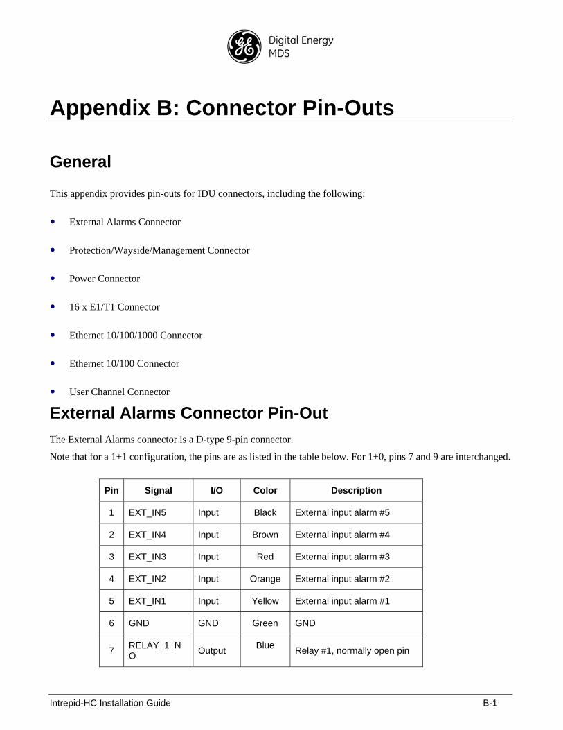
External Alarms Connector Pin-Out
The External Alarms connector is a D-type 9-pin connector.
Note that for a 1+1 configuration, the pins are as listed in the table below. For 1+0, pins 7 and 9 are interchanged.
Pin Signal I/O Color Description
1 EXT_IN5 Input Black External input alarm #5
2 EXT_IN4 Input Brown External input alarm #4
3 EXT_IN3 Input Red External input alarm #3
4 EXT_IN2 Input Orange External input alarm #2
5 EXT_IN1 Input Yellow External input alarm #1
6 GND GND Green GND
7 RELAY_1_NO
Output Blue
Relay #1, normally open pin
Intrepid-HC Installation Guide B-2
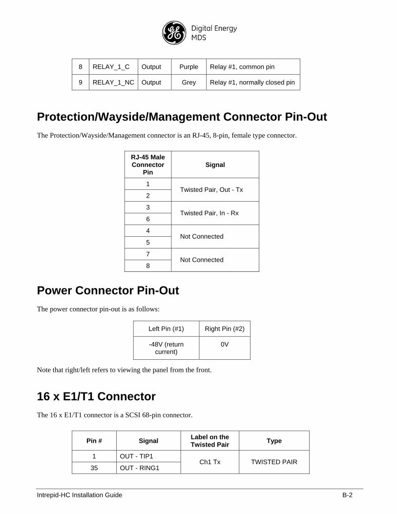
8 RELAY_1_C Output Purple Relay #1, common pin
9 RELAY_1_NC Output Grey Relay #1, normally closed pin
Protection/Wayside/Management Connector Pin-Out
The Protection/Wayside/Management connector is an RJ-45, 8-pin, female type connector.
RJ-45 Male Connector
Pin Signal
1
2 Twisted Pair, Out - Tx
3
6 Twisted Pair, In - Rx
4
5 Not Connected
7
8 Not Connected
Power Connector Pin-Out
The power connector pin-out is as follows:
Left Pin (#1) Right Pin (#2)
-48V (return current)
0V
Note that right/left refers to viewing the panel from the front.
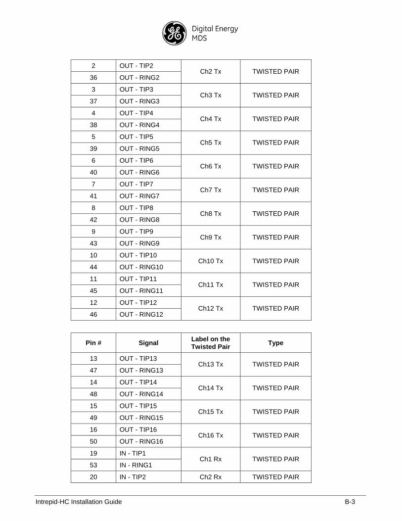
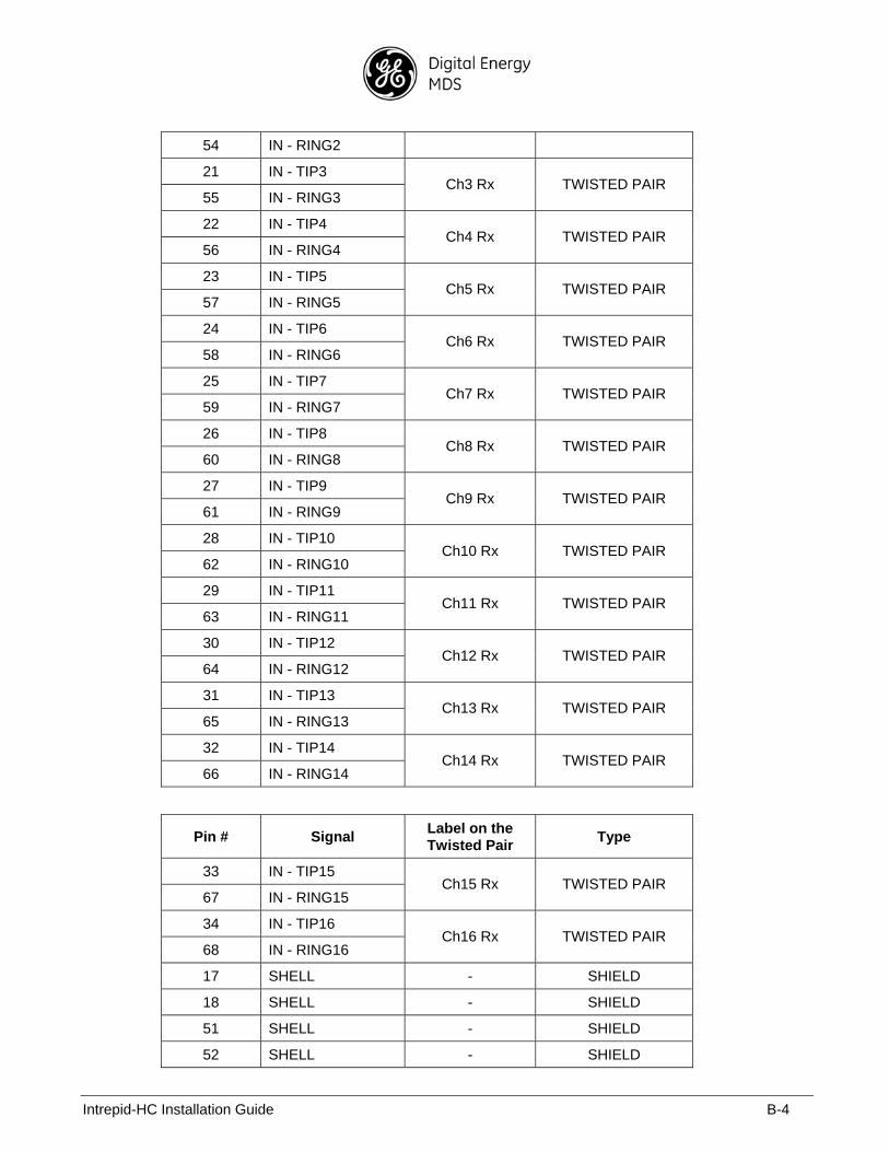
16 x E1/T1 Connector
The 16 x E1/T1 connector is a SCSI 68-pin connector.
Pin # Signal Label on the Twisted Pair
Type
1 OUT - TIP1
35 OUT - RING1 Ch1 Tx TWISTED PAIR
Intrepid-HC Installation Guide B-3
2 OUT - TIP2
36 OUT - RING2 Ch2 Tx TWISTED PAIR
3 OUT - TIP3
37 OUT - RING3 Ch3 Tx TWISTED PAIR
4 OUT - TIP4
38 OUT - RING4 Ch4 Tx TWISTED PAIR
5 OUT - TIP5
39 OUT - RING5 Ch5 Tx TWISTED PAIR
6 OUT - TIP6
40 OUT - RING6 Ch6 Tx TWISTED PAIR
7 OUT - TIP7
41 OUT - RING7 Ch7 Tx TWISTED PAIR
8 OUT - TIP8
42 OUT - RING8 Ch8 Tx TWISTED PAIR
9 OUT - TIP9
43 OUT - RING9 Ch9 Tx TWISTED PAIR
10 OUT - TIP10
44 OUT - RING10 Ch10 Tx TWISTED PAIR
11 OUT - TIP11
45 OUT - RING11 Ch11 Tx TWISTED PAIR
12 OUT - TIP12
46 OUT - RING12 Ch12 Tx TWISTED PAIR
Pin # Signal Label on the Twisted Pair
Type
13 OUT - TIP13
47 OUT - RING13 Ch13 Tx TWISTED PAIR
14 OUT - TIP14
48 OUT - RING14 Ch14 Tx TWISTED PAIR
15 OUT - TIP15
49 OUT - RING15 Ch15 Tx TWISTED PAIR
16 OUT - TIP16
50 OUT - RING16 Ch16 Tx TWISTED PAIR
19 IN - TIP1
53 IN - RING1 Ch1 Rx TWISTED PAIR
20 IN - TIP2 Ch2 Rx TWISTED PAIR
Intrepid-HC Installation Guide B-4
54 IN - RING2
21 IN - TIP3
55 IN - RING3 Ch3 Rx TWISTED PAIR
22 IN - TIP4
56 IN - RING4 Ch4 Rx TWISTED PAIR
23 IN - TIP5
57 IN - RING5 Ch5 Rx TWISTED PAIR
24 IN - TIP6
58 IN - RING6 Ch6 Rx TWISTED PAIR
25 IN - TIP7
59 IN - RING7 Ch7 Rx TWISTED PAIR
26 IN - TIP8
60 IN - RING8 Ch8 Rx TWISTED PAIR
27 IN - TIP9
61 IN - RING9 Ch9 Rx TWISTED PAIR
28 IN - TIP10
62 IN - RING10 Ch10 Rx TWISTED PAIR
29 IN - TIP11
63 IN - RING11 Ch11 Rx TWISTED PAIR
30 IN - TIP12
64 IN - RING12 Ch12 Rx TWISTED PAIR
31 IN - TIP13
65 IN - RING13 Ch13 Rx TWISTED PAIR
32 IN - TIP14
66 IN - RING14 Ch14 Rx TWISTED PAIR
Pin # Signal Label on the Twisted Pair
Type
33 IN - TIP15
67 IN - RING15 Ch15 Rx TWISTED PAIR
34 IN - TIP16
68 IN - RING16 Ch16 Rx TWISTED PAIR
17 SHELL - SHIELD
18 SHELL - SHIELD
51 SHELL - SHIELD
52 SHELL - SHIELD
Intrepid-HC Installation Guide B-5
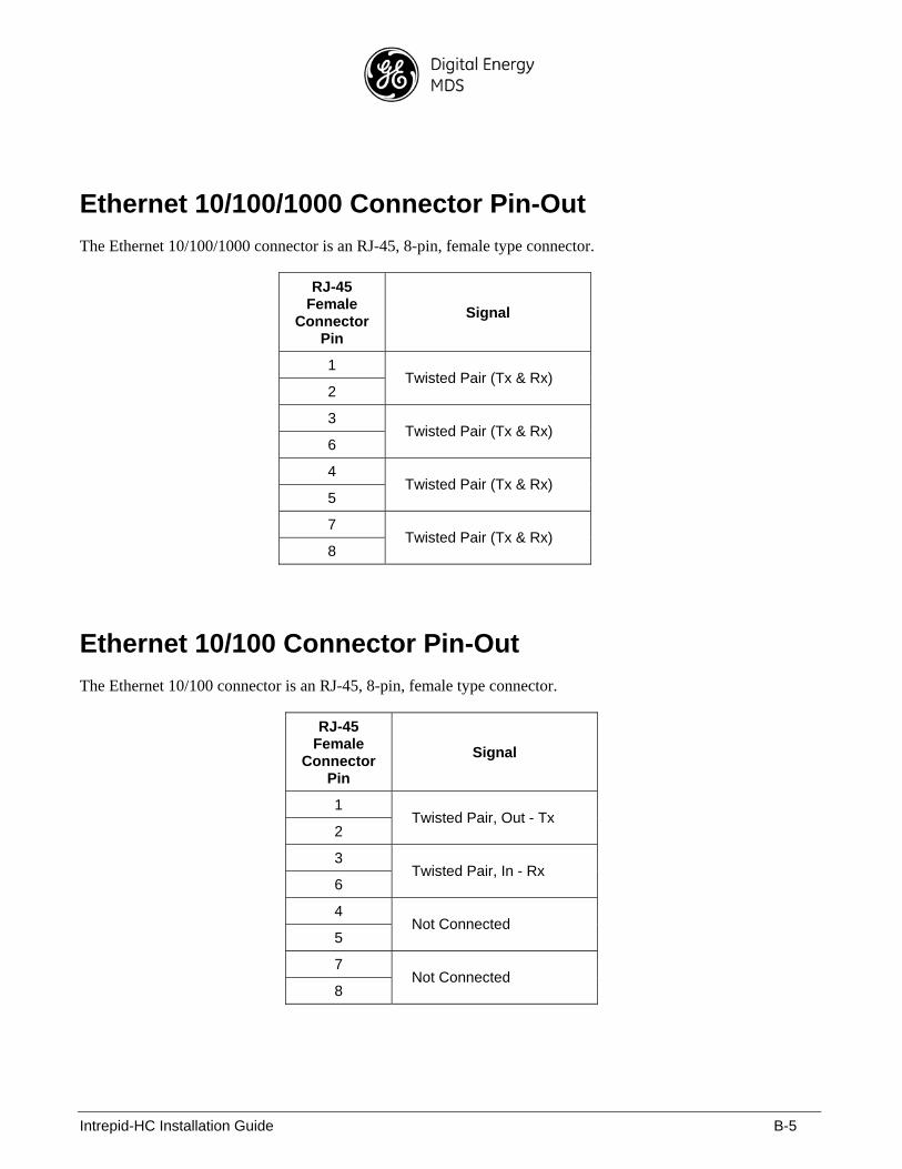
Ethernet 10/100/1000 Connector Pin-Out
The Ethernet 10/100/1000 connector is an RJ-45, 8-pin, female type connector.
RJ-45 Female
Connector Pin
Signal
1
2 Twisted Pair (Tx & Rx)
3
6 Twisted Pair (Tx & Rx)
4
5 Twisted Pair (Tx & Rx)
7
8 Twisted Pair (Tx & Rx)
Ethernet 10/100 Connector Pin-Out
The Ethernet 10/100 connector is an RJ-45, 8-pin, female type connector.
RJ-45 Female
Connector Pin
Signal
1
2 Twisted Pair, Out - Tx
3
6 Twisted Pair, In - Rx
4
5 Not Connected
7
8 Not Connected
Intrepid-HC Installation Guide B-6
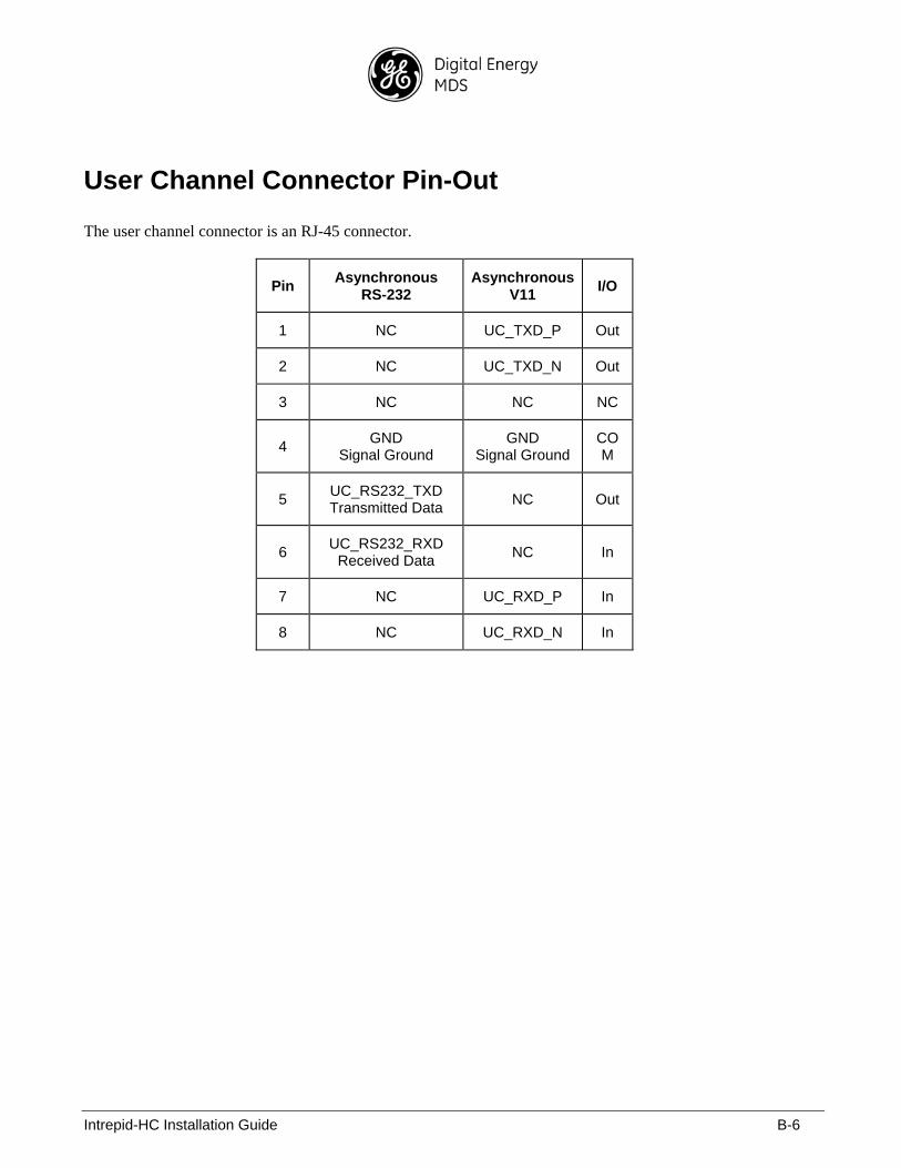
User Channel Connector Pin-Out
The user channel connector is an RJ-45 connector.
Pin Asynchronous
RS-232 Asynchronous
V11 I/O
1 NC UC_TXD_P Out
2 NC UC_TXD_N Out
3 NC NC NC
4 GND
Signal Ground GND
Signal Ground COM
5 UC_RS232_TXD Transmitted Data
NC Out
6 UC_RS232_RXD
Received Data NC In
7 NC UC_RXD_P In
8 NC UC_RXD_N In
Intrepid-HC Installation Guide C-1
Appendix C: Protection Information
General
This appendix provides information about the Intrepid-HC protection equipment.
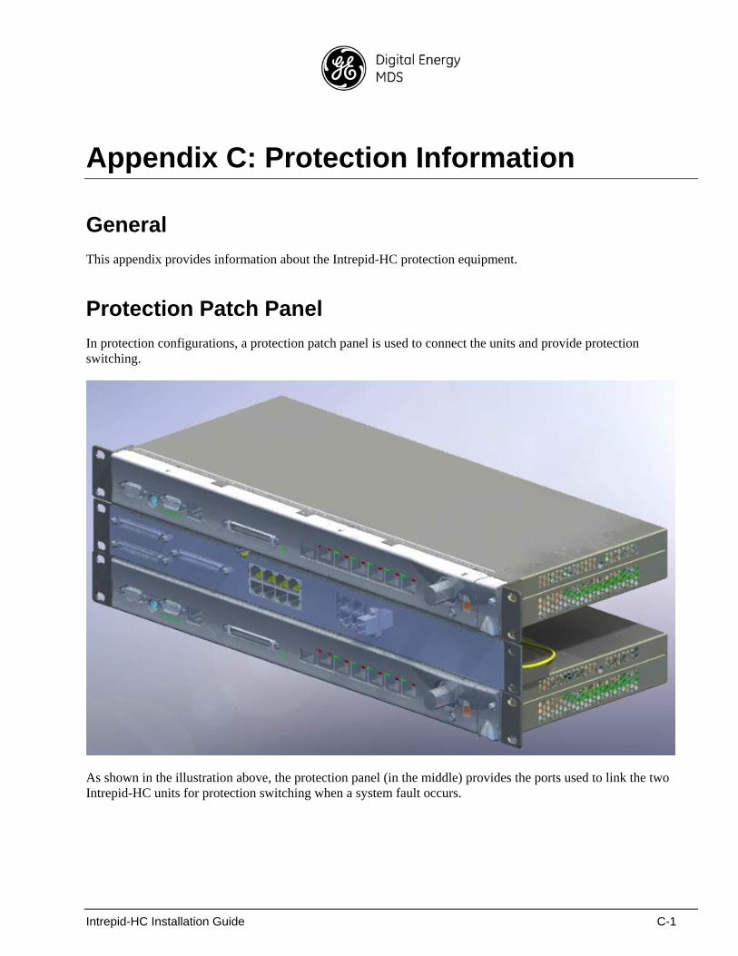
Protection Patch Panel
In protection configurations, a protection patch panel is used to connect the units and provide protection switching.
As shown in the illustration above, the protection panel (in the middle) provides the ports used to link the two Intrepid-HC units for protection switching when a system fault occurs.
Intrepid-HC Installation Guide C-2
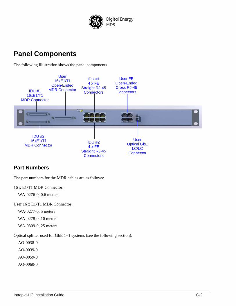
Panel Components
The following illustration shows the panel components.
Part Numbers
The part numbers for the MDR cables are as follows:
16 x E1/T1 MDR Connector:
WA-0276-0, 0.6 meters
User 16 x E1/T1 MDR Connector:
WA-0277-0, 5 meters
WA-0278-0, 10 meters
WA-0309-0, 25 meters
Optical splitter used for GbE 1+1 systems (see the following section):
AO-0038-0
AO-0039-0
AO-0059-0
AO-0060-0
IDU #2 16xE1/T1
MDR Connector
IDU #1 16xE1/T1
MDR Connector
User 16xE1/T1
Open-Ended MDR Connector
User Optical GbE
LC/LC Connector
IDU #1 4 x FE
Straight RJ-45Connectors
User FE Open-EndedCross RJ-45Connectors
IDU #2 4 x FE
Straight RJ-45Connectors
Intrepid-HC Installation Guide C-3
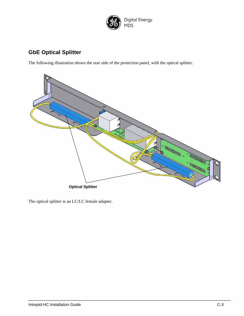
GbE Optical Splitter
The following illustration shows the rear side of the protection panel, with the optical splitter.
The optical splitter is an LC/LC female adapter.
Optical Splitter

Intrepid-HC Installation Guide C-4
Intrepid-HC Installation Guide D-1
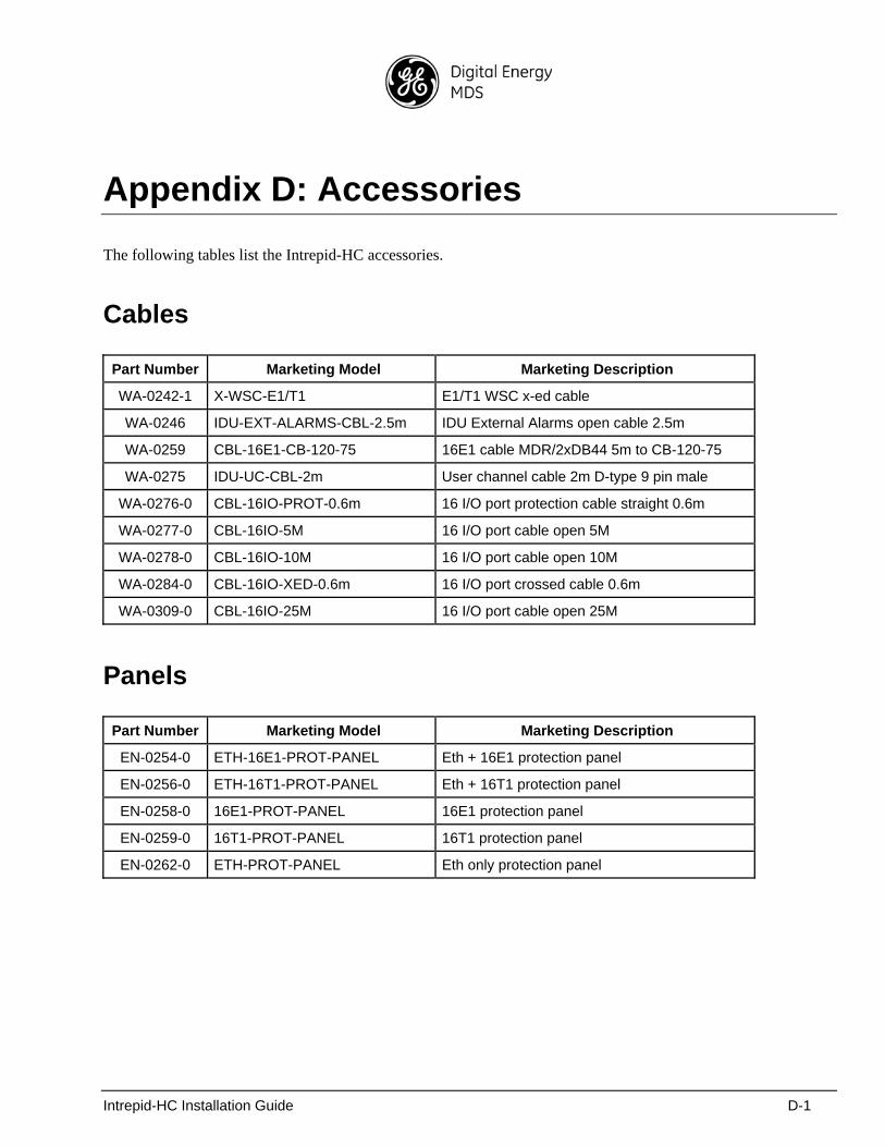
Appendix D: Accessories
The following tables list the Intrepid-HC accessories.
Cables
Part Number Marketing Model Marketing Description
WA-0242-1 X-WSC-E1/T1 E1/T1 WSC x-ed cable
WA-0246 IDU-EXT-ALARMS-CBL-2.5m IDU External Alarms open cable 2.5m
WA-0259 CBL-16E1-CB-120-75 16E1 cable MDR/2xDB44 5m to CB-120-75
WA-0275 IDU-UC-CBL-2m User channel cable 2m D-type 9 pin male
WA-0276-0 CBL-16IO-PROT-0.6m 16 I/O port protection cable straight 0.6m
WA-0277-0 CBL-16IO-5M 16 I/O port cable open 5M
WA-0278-0 CBL-16IO-10M 16 I/O port cable open 10M
WA-0284-0 CBL-16IO-XED-0.6m 16 I/O port crossed cable 0.6m
WA-0309-0 CBL-16IO-25M 16 I/O port cable open 25M
Panels
Part Number Marketing Model Marketing Description
EN-0254-0 ETH-16E1-PROT-PANEL Eth + 16E1 protection panel
EN-0256-0 ETH-16T1-PROT-PANEL Eth + 16T1 protection panel
EN-0258-0 16E1-PROT-PANEL 16E1 protection panel
EN-0259-0 16T1-PROT-PANEL 16T1 protection panel
EN-0262-0 ETH-PROT-PANEL Eth only protection panel
Intrepid-HC Installation Guide D-2
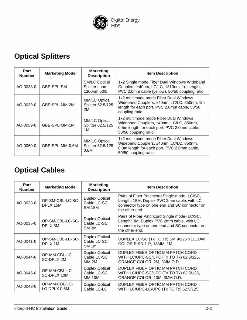
Optical Splitters
Part Number
Marketing Model Marketing
Description Item Description
AO-0038-0 GBE-SPL-SM SM/LC Optical Splitter conn. 1300nm 50/5
1x2 Single mode Fiber Dual Windows Wideband Couplers, ±40nm, LC/LC, 1310nm, 1m length, PVC 2.0mm cable (yellow), 50/50 coupling ratio.
AO-0039-0 GBE-SPL-MM-2M MM/LC Optical Splitter 62.5/125 2M
1x2 multimode mode Fiber Dual Windows Wideband Couplers, ±40nm, LC/LC, 850nm, 1m length for each port, PVC 2.0mm cable, 50/50 coupling ratio
AO-0059-0 GBE-SPL-MM-1M MM/LC Optical Splitter 62.5/125 1M
1x2 multimode mode Fiber Dual Windows Wideband Couplers, ±40nm, LC/LC, 850nm, 0.5m length for each port, PVC 2.0mm cable, 50/50 coupling ratio
AO-0060-0 GBE-SPL-MM-0.6M MM/LC Optical Splitter 62.5/125 0.6M
1x2 multimode mode Fiber Dual Windows Wideband Couplers, ±40nm, LC/LC, 850nm, 0.3m length for each port, PVC 2.0mm cable, 50/50 coupling ratio
Optical Cables
Part Number
Marketing Model Marketing
Description Item Description
AO-0033-0 OP-SM-CBL-LC-SC-DPLX 15M
Duplex Optical Cable LC-SC SM 15M
Pairs of Fiber Patchcord Single mode- LC/SC, Length: 15M, Duplex PVC 2mm cable, with LC connector type on one end and SC connector on the other end.
AO-0035-0 OP-SM-CBL-LC-SC-DPLX 3M
Duplex Optical Cable LC-SC SM 3M
Pairs of Fiber Patchcord Single mode- LC/SC, Length: 3M, Duplex PVC 2mm cable, with LC connector type on one end and SC connector on the other end.
AO-0041-0 OP-SM-CBL-LC-SC-DPLX 1M
Duplex Optical Cable LC-SC SM 1m
DUPLEX LC-SC (Tx TO Tx) SM 9/125 YELLOW COLOR R-9D-1-P, 13MM, 1M
AO-0044-0 OP-MM-CBL-LC-SC-DPLX 2M
Duplex Optical Cable LC-SC MM 2M
DUPLEX FIBER OPTIC MM PATCH CORD WITH LC/UPC-SC/UPC (Tx TO Tx) 62.5/125, ORANGE COLOR, 2M, 3MM O.D.
AO-0045-0 OP-MM-CBL-LC-SC-DPLX 10M
Duplex Optical Cable LC-SC MM 10M
DUPLEX FIBER OPTIC MM PATCH CORD WITH LC/UPC-SC/UPC (Tx TO Tx) 62.5/125, ORANGE COLOR, 10M, 3MM O.D.
AO-0048-0 OP-MM-CBL-LC-LC-DPLX 0.5M
Duplex Optical Cable LC-LC
DUPLEX FIBER OPTIC MM PATCH CORD WITH LC/UPC-LC/UPC (Tx TO Tx) 62.5/125
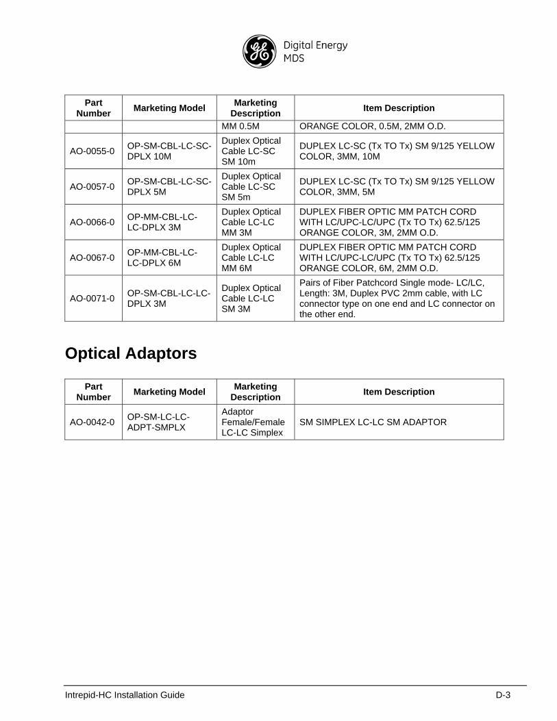
Intrepid-HC Installation Guide D-3
Part Number
Marketing Model Marketing
Description Item Description
MM 0.5M ORANGE COLOR, 0.5M, 2MM O.D.
AO-0055-0 OP-SM-CBL-LC-SC-DPLX 10M
Duplex Optical Cable LC-SC SM 10m
DUPLEX LC-SC (Tx TO Tx) SM 9/125 YELLOW COLOR, 3MM, 10M
AO-0057-0 OP-SM-CBL-LC-SC-DPLX 5M
Duplex Optical Cable LC-SC SM 5m
DUPLEX LC-SC (Tx TO Tx) SM 9/125 YELLOW COLOR, 3MM, 5M
AO-0066-0 OP-MM-CBL-LC-LC-DPLX 3M
Duplex Optical Cable LC-LC MM 3M
DUPLEX FIBER OPTIC MM PATCH CORD WITH LC/UPC-LC/UPC (Tx TO Tx) 62.5/125 ORANGE COLOR, 3M, 2MM O.D.
AO-0067-0 OP-MM-CBL-LC-LC-DPLX 6M
Duplex Optical Cable LC-LC MM 6M
DUPLEX FIBER OPTIC MM PATCH CORD WITH LC/UPC-LC/UPC (Tx TO Tx) 62.5/125 ORANGE COLOR, 6M, 2MM O.D.
AO-0071-0 OP-SM-CBL-LC-LC-DPLX 3M
Duplex Optical Cable LC-LC SM 3M
Pairs of Fiber Patchcord Single mode- LC/LC, Length: 3M, Duplex PVC 2mm cable, with LC connector type on one end and LC connector on the other end.
Optical Adaptors
Part Number
Marketing Model Marketing
Description Item Description
AO-0042-0 OP-SM-LC-LC-ADPT-SMPLX
Adaptor Female/Female LC-LC Simplex
SM SIMPLEX LC-LC SM ADAPTOR

Intrepid-HC Installation Guide D-4
Intrepid-HC Installation Guide E-1
Appendix E: Fan Tray Replacement
Fan Tray Replacement Procedure
If it becomes necessary to replace the fan tray in the IDU, proceed as follows:
1. Remove the current fan tray by releasing the safety screw and removing the tray.
2. Insert the new fan tray entirely in its place and tighten the safety screw.

Intrepid-HC Installation Guide E-2
IN CASE OF DIFFICULTY...
GE MDS products are designed for long life and trouble-free operation. However, this equipment, as with all electronic equipment, may have an occasional component failure. The following information will assist you in the event that servicing becomes necessary.
TECHNICAL ASSISTANCE
Technical assistance for GE MDS products is available from our Technical Support Department during business hours (8:30 A.M.–6:00 P.M. Eastern Time). When calling, please give the complete model number of the radio, along with a description of the trouble/symptom(s) that you are experiencing. In many cases, problems can be resolved over the telephone, without the need for returning the unit to the factory. Please use one of the following means for product assistance:
Phone: 585 241-5510 E-Mail: [email protected]
FAX: 585 242-8369 Web: www.gemds.com
FACTORY SERVICE
Component level repair of this equipment is not recommended in the field. Many components are installed using surface mount technology, which requires specialized training and equipment for proper servicing. For this reason, the equipment should be returned to the factory for any PC board repairs. The factory is best equipped to diagnose, repair and align your radio to its proper operating specifications.
If return of the equipment is necessary, you must obtain a Service Request Order (SRO) number. This number helps expedite the repair so that the equipment can be repaired and returned to you as quickly as possible. Please be sure to include the SRO number on the outside of the shipping box, and on any corre-spondence relating to the repair. No equipment will be accepted for repair without an SRO number.
SRO numbers are issued online at www.GEmds.com/support/product/sro/. Your number will be issued immediately after the required information is entered. Please be sure to have the model number(s), serial number(s), detailed reason for return, "ship to" address, "bill to" address, and contact name, phone number, and fax number available when requesting an SRO number. A purchase order number or pre-payment will be required for any units that are out of warranty, or for product conversion.
If you prefer, you may contact our Product Services department to obtain an SRO number:
Phone Number: 585-241-5540Fax Number: 585-242-8400E-mail Address: [email protected]
The radio must be properly packed for return to the factory. The original shipping container and packaging materials should be used whenever possible. All factory returns should be addressed to:
GE MDS, LLCProduct Services Department(SRO No. XXXX)175 Science ParkwayRochester, NY 14620 USA
When repairs have been completed, the equipment will be returned to you by the same shipping method used to send it to the factory. Please specify if you wish to make different shipping arrangements. To inquire about an in-process repair, you may contact our Product Services Group using the telephone, Fax, or E-mail information given above.

GE MDS, LLC
Rochester, NY 14620General Business: +1 585 242-9600
FAX: +1 585 242-9620Web: www.gemds.com
175 Science Parkway