4.7 permeable pavement - credit valley conservation · 4.7 permeable pavement 4.7.1 overview ......
TRANSCRIPT
Low Impact Development Stormwater Management Planning and Design Guide
4-111 Version 1.0
4.7 Permeable Pavement
4.7.1 Overview Description Permeable pavements, an alternative to traditional impervious pavement, allow stormwater to drain through them and into a stone reservoir where it is infiltrated into the underlying native soil or temporarily detained. They can be used for low traffic roads, parking lots, driveways, pedestrian plazas and walkways. Permeable pavement is ideal for sites with limited space for other surface stormwater BMPs. The following permeable pavement types are illustrated in Figure 4.7.1:
• permeable interlocking concrete pavers (i.e., block pavers); • plastic or concrete grid systems (i.e., grid pavers); • pervious concrete; and • porous asphalt.
Depending on the native soils and physical constraints, the system may be designed with no underdrain for full infiltration, with an underdrain for partial infiltration, or with an impermeable liner and underdrain for a no infiltration or detention and filtration only practice (Figure 4.7.3). Permeable paving allows for filtration, storage, or infiltration of runoff, and can reduce or eliminate surface stormwater flows compared to traditional impervious paving surfaces like concrete and asphalt. Common Concerns Common concerns about permeable paving include the following:
� Risk of Groundwater Contamination: Most pollutants in urban runoff are well retained by infiltration practices and soils and therefore, have a low to moderate potential for groundwater contamination (Pitt et al., 1999). Chloride and sodium from de-icing salts applied to roads and parking areas during winter are not well attenuated in soil and can easily travel to shallow groundwater. Infiltration of de-icing salt constituents is also known to increase the mobility of certain heavy metals in soil (e.g., lead, copper and cadmium), thereby raising the potential for elevated concentrations in underlying groundwater (Amrhein et al., 1992; Bauske and Goetz, 1993). However, very few studies that have sampled groundwater below infiltration facilities or roadside ditches receiving de-icing salt laden runoff have found concentrations of heavy metals that exceed drinking water standards (e.g., Howard and Beck, 1993; Granato et al., 1995). To minimize risk of groundwater contamination the following management approaches are recommended (Pitt et al., 1999; TRCA, 2009b):
o stormwater infiltration practices should not receive runoff from high traffic areas where large amounts of de-icing salts are applied (e.g., busy highways), nor from pollution hot spots (e.g., source areas where land uses or activities have the potential to generate highly contaminated runoff such as vehicle fuelling, servicing or demolition areas, outdoor storage or handling areas for hazardous materials and some heavy industry sites);

Low Impact Development Stormwater Management Planning and Design Guide
4-112 Version 1.0
o prioritize infiltration of runoff from source areas that are comparatively less contaminated such as roofs, low traffic roads and parking areas; and,
o apply sedimentation pretreatment practices (e.g., oil and grit separators) before infiltration of road or parking area runoff.
� Risk of Soil Contamination: Available evidence from monitoring studies indicates
that small distributed stormwater infiltration practices do not contaminate underlying soils, even after more than 10 years of operation (TRCA, 2008).
� Winter Operation: For cold climates, well-designed mixes can meet strength,
permeability, and freeze-thaw resistance requirements. In addition, experience suggests that snow melts faster on a porous surface because of rapid drainage below the snow surface. Also, a well draining surface will reduce the occurrence of black ice or frozen puddles (Cahill Associates, 1993; Roseen, 2007). Systems installed in the Greater Toronto Area have generally not suffered from heaving or slumping (TRCA, 2008b). Permeable pavement is typically designed to drain within 48 hours. If freezing should occur before the pavement structure has drained, then the large void spaces in the open graded aggregate base creates a capillary barrier to freeze-thaw. Permeable pavers have the added benefit of having enough flexibility to handle minor heaving without being damaged. Permeable pavement can be plowed, although raising the blade height 25 mm may be helpful to avoid catching pavers or scraping the rough surface of the porous pavement. Sand should not be applied for winter traction on permeable pavement as this can quickly clog the system.
� On Private Property: If permeable pavement systems are installed on private lots, property owners or managers will need to be educated on their routine maintenance needs, understand the long-term maintenance plan, and may be subject to a legally binding maintenance agreement. An incentive program such as a storm sewer user fee based on the area of impervious cover on a property that is directly connected to a storm sewer (i.e., does not first drain to a pervious area or LID practice) could be used to encourage property owners or managers to maintain existing practices.
� Clogging: Susceptibility to clogging is the main concern for permeable paving systems. The bedding layer and joint filler should consist of 2.5 mm clear stone or gravel rather than sand. Key strategies to prevent clogging are to ensure that adjacent pervious areas have adequate vegetation cover and a winter maintenance plan that does not include sanding. For concrete and asphalt designs, regular maintenance that includes vacuum-assisted street sweeping is necessary. Isolated areas of clogging can be remedied by drilling small holes in the pavement or by replacing the media between permeable pavers.

Low Impact Development Stormwater Management Planning and Design Guide
4-113 Version 1.0
Figure 4.7.1 Permeable pavement types
Permeable interlocking concrete pavers (block paver s): Concrete pavers are designed with gaps between them that allow stormwater to infiltrate into the aggregate reservoir. The gaps are approximately 10% of the surface area and are filled with small stone.
Permeable paver parking lot in Mississauga, ON (Source: CVC)
Plastic or concrete grid systems are concrete or durable plastic grids filled with gravel or a pervious planting mix for grass or low ground cover. The grids provide support for vehicles or foot traffic while preventing compaction and rutting of the fill material. Grid systems are appropriate for applications such as walkways, overflow parking, firelanes, maintenance and utility acccess lanes, or driveways.
Residential driveway (Source: R. Bannerman); Plastic grid filled with gravel (Source: Gravelpave©)
Pervious Concrete and Porous Asphalt have pavement mixes with reduced or no fines which creates stable void spaces. The void spaces allow stormwater to drain through to the underlying stone reservoir. They require different pouring and setting procedures than their impervious versions.
Pervious concrete(Source: Hunt and Collins, 2008); Porous asphalt parking lot (Source: University of New
Hampshire Stormwater Center)

Low Impact Development Stormwater Management Planning and Design Guide
4-114 Version 1.0
� Road Salt: Care needs to be taken when applying road salt to permeable pavement surfaces since dissolved constituents from the road salt will migrate through the bedding and into the groundwater system. A well draining surface will reduce the occurrence of black ice or frozen puddles and requires less salt than is applied to impervious pavement (Roseen, 2007).
� Structural Stability: Adherence to design guidelines for pavement design and
base courses will ensure structural stability. In most cases, the depth of aggregate material required for the stormwater storage reservoir will exceed the depth necessary for structural stability. Reinforcing grids can be installed in the bedding for applications that will be subject to very heavy loads.
� Heavy Vehicle Traffic: Permeable pavement is not typically used in locations
subject to heavy loads. Some permeable pavers are designed for heavy loads and have been used in commercial port loading and storage areas.
Physical Suitability and Constraints In general, permeable pavement systems can be used almost anywhere a traditionally paved system might have been installed. However, these systems have the same site constraints of any infiltration practice and should meet the following criteria:
� Wellhead Protection: Permeable pavement should not be used for road or parking surfaces within two (2) year time-of-travel wellhead protection areas.
� Winter Operations: Sand or other granular materials should not be applied as
anti-skid agents during winter operation because they can quickly clog the system. Winter maintenance practices should be limited to plowing, with de-icing salts applied sparingly (i.e., not as a preventative measure).
� Site Topography: The slope of the permeable pavement surface should be at
least one percent and no greater than five percent. The impervious land surrounding and draining into the pavement should not exceed 20% slope (Smith, 2006). Pervious surfaces should not drain onto the pavement.
� Water Table: The base of permeable pavement stone reservoir should be at least
one (1) metre above the seasonally high water table or bedrock elevation.
� Soils: Systems located in low permeability soils with an infiltration rate of less than 15 mm/hr (i.e., hydraulic conductivity of less than 1x10 -6 cm/s), require incorporation of a perforated pipe underdrain. Native soil infiltration rate at the proposed location and depth should be confirmed through measurement of hydraulic conductivity under field saturated conditions using methods described in Appendix C.
� Drainage Area and Runoff Volume: In general, the impervious area treated
should not exceed 1.2 times the area of permeable pavement which receives the runoff (GVRD, 2005). The storage layer under the permeable pavement must be
Low Impact Development Stormwater Management Planning and Design Guide
4-115 Version 1.0
sized to accommodate runoff from the pavement itself and any impermeable areas draining to it.
• Pollution Hot Spot Runoff: To protect groundwater from possible contamination,
source areas where land uses or human activities have the potential to generate highly contaminated runoff (e.g., vehicle fueling, servicing and demolition areas, outdoor storage and handling areas for hazardous materials and some heavy industry sites) should not be treated by permeable pavement.
� Setbacks from Buildings: Permeable pavement should be located downslope
from building foundations. If the pavement does not receive runoff from other surfaces, no setback is required from building foundations. Otherwise, a minimum setback of four (4) metres down-gradient from building foundations is recommended.
� Proximity to Underground Utilities: Local utility design guidance should be
consulted to define the horizontal and vertical offsets. Generally, requirements for underground utilities passing under or near permeable pavement will be no different than for utilities in other pervious areas. However, permeable pavement has a deeper base than conventional pavement which may impact shallow utilities.
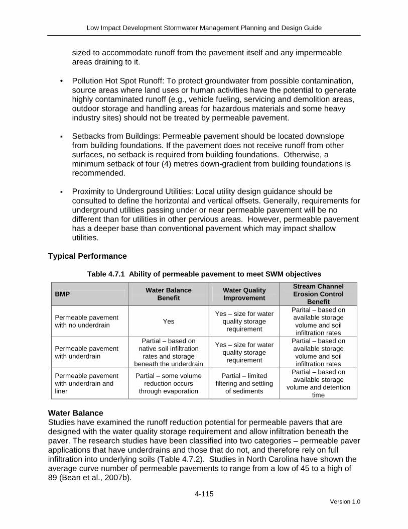
Typical Performance
Table 4.7.1 Ability of permeable pavement to meet SWM objectives
BMP Water Balance Benefit
Water Quality Improvement
Stream Channel Erosion Control
Benefit
Permeable pavement with no underdrain Yes
Yes – size for water quality storage
requirement
Parital – based on available storage volume and soil infiltration rates
Permeable pavement with underdrain
Partial – based on native soil infiltration
rates and storage beneath the underdrain
Yes – size for water quality storage
requirement
Partial – based on available storage volume and soil infiltration rates
Permeable pavement with underdrain and liner
Partial – some volume reduction occurs
through evaporation
Partial – limited filtering and settling
of sediments
Partial – based on available storage
volume and detention time
Water Balance Studies have examined the runoff reduction potential for permeable pavers that are designed with the water quality storage requirement and allow infiltration beneath the paver. The research studies have been classified into two categories – permeable paver applications that have underdrains and those that do not, and therefore rely on full infiltration into underlying soils (Table 4.7.2). Studies in North Carolina have shown the average curve number of permeable pavements to range from a low of 45 to a high of 89 (Bean et al., 2007b).

Low Impact Development Stormwater Management Planning and Design Guide
4-116 Version 1.0
Table 4.7.2 Volumetric runoff reduction 1 from permeable pavement
LID Practice Location Runoff Reduction 1 Reference
Guelph, Ontario 90% James (2002)
Pennsylvania 90% Kwiatkowski et al. (2007)
France 97% Legret and Colandini (1999)
Washington 97 to 100% Brattebo and Booth (2003)
Permeable pavement without underdrain
Connecticut 72%2 Gilbert and Clausen (2006)
King City, Ontario 99%4 TRCA (2008b)
North Carolina 98 to 99% Collins et al. (2008)
United Kingdom 50% Jefferies (2004)
United Kingdom 53 to 66% Pratt et al., 1995
Permeable pavement with underdrain
Maryland 45 to 60% Schueler et al. (1987)
Runoff Reduction Estimate 3 85% without underdrain; 45% with underdrain
Notes: 1. Runoff reduction estimates are based on differences between runoff volume from the practice and total
precipitation over the period of monitoring unless otherwise noted. 2. Runoff reduction estimates are based on differences in runoff volume between the practice and a
conventional impervious surface over the period of monitoring. 3. This estimate is provided only for the purpose of initial screening of LID practices suitable for achieving
stormwater management objectives and targets. Performance of individual facilities will vary depending on site specific contexts and facility design parameters and should be estimated as part of the design process and submitted with other documentation for review by the approval authority.
4. In this study, there was no underdrain in the pavement base, but an underdrain was located 1 m below the native soils to allow for sampling of infiltrated water.
Water Quality - Pollutant Removal Capacity Like other infiltration practices, the capacity of permeable pavements to remove pollutants is closely associated with their ability to infiltrate runoff. Full infiltration designs are more effective because little if any of the pollutants generated on the impermeable surfaces leave the site as surface runoff. Partial infiltration designs with underdrains generate more runoff, and as a result, are often used in studies investigating the water quality impact of permeable pavements on surface waters. These studies show load reductions above 50% for total suspended solids, most metals, and hydrocarbons (Legret and Collandini, 1999); Pratt et al., 1995); Pagotto et al., 2000). A substantial portion of the pollutants are captured in the surface pores and underlying granular base of the permeable pavements (Pratt et al., 1995). Another group of studies of permeable pavements examines the quality of water infiltrated through soils beneath the installations. In these studies the quality of infiltrated water is used as a measure of the potential for contamination of groundwater. One such study of a permeable interlocking concrete pavement installed in a college parking lot in King City, Ontario, showed that stormwater infiltrated through a 60 cm granular reservoir and 1 metre of native soil had significantly lower concentrations of several typical parking lot contaminants relative to runoff from an adjacent asphalt surface (TRCA, 2008b). These results are consistent with research on the quality of infiltrated water from permeable pavements in Washington (Brattebo and Booth, 2003) and Pennsylvannia (Kwiatkowski et al., 2007). As with all stormwater infiltration practices, risk of groundwater contamination from infiltration of runoff laden with road

Low Impact Development Stormwater Management Planning and Design Guide
4-117 Version 1.0
de-icing salt constituents (typically sodium and chloride) is a significant concern. Chloride ions are extremely mobile in the soil and are readily transported by percolating water to aquifers. Stream Channel Erosion Control The storage capacity of a specific system should be compared to the channel erosion control detention requirement. Limits to the depth of the stone base are discussed in the Design Template part of Section 4.7.2. Other Benefits
• Winter Performance: Snow plow and deicing costs are reduced due to rapid snow and ice melt drainage. Puddling and flooding on parking lots is also reduced.
• Urban Heat Island Effect Reduction: Porous materials have less thermal conductivity and thermal capacity than traditional impervious pavement, thereby reducing the urban heat island effect (Ferguson, 2005).
• Quiet Streets: Porous surfaces absorb sound energy and dissipate air pressure around tires before any noise is generated. Tire noise is lower in loudness and pitch for a porous surface than a corresponding dense pavement (Ferguson, 2005).
• LEED Credits: Permeable pavement has the potential for earning Canadian
Green Building Council LEED sustainable sites credits for reducing stormwater pollution and runoff, urban heat island mitigation, and conservation of materials and resources.
4.7.2 Design Template Applications Permeable pavements are designed to provide treatment for the rain that falls directly onto their surface, but can also be designed to receive runoff from adjacent conventional paving and building roof downspouts. They are particularly useful in high density areas with limited space for other stormwater BMPs. Treatment of runoff from pervious areas is discouraged due to clogging potential. Permeable pavement may be applied on residential lots, school grounds, parks, shopping centres, and around commercial, institutional or municipal buildings (Figure 4.7.2). Permeable pavement practices should not be applied in pollution hot spots such as vehicle fuelling, service or demolition areas, outdoor storage and handling areas for hazardous materials and some heavy industry sites.

Low Impact Development Stormwater Management Planning and Design Guide
4-118 Version 1.0
Figure 4.7.2 Examples of permeable pavement applic ations
Pervious Concrete
Pervious concrete walkway plaza (Source: Villanova Urban Stormwater Partnership)
Pervious concrete applied to an alleyway in
Chicago (Source: City of Chicago) Porous Asphalt
Porous asphalt parking lot (Source: Villanova
Urban Stormwater Partnership)
Porous asphalt installed curb to curb on a residential street (Source: City of Portland,
Bureau of Environmental Services) Permeable Interlocking Concrete Pavers
Permeable pavers used in combination with bioretention in a parking lot in Elmhurst, IL
(Source: ICPI).
Permeable pavers in Hoboken, NJ used around
trees which allow air and water to reach the roots (Source: Bruce Ferguson).
Low Impact Development Stormwater Management Planning and Design Guide
4-119 Version 1.0
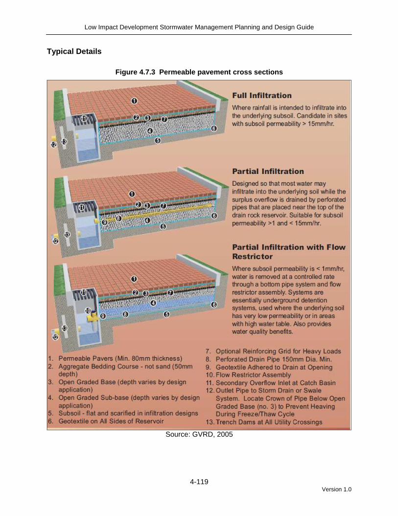
Typical Details
Figure 4.7.3 Permeable pavement cross sections
Source: GVRD, 2005

Low Impact Development Stormwater Management Planning and Design Guide
4-120 Version 1.0
Figure 4.7.4 Close up cross section of permeable p avement full infiltration design
Source: Smith, 2006
*Note the detail above, along with most specifications for permeable pavement, use the US ASTM
reference numbers to refer to aggregate mixes. Generally, ASTM #8 = 5 mm clear crush open graded bedding course; ASTM #57 = 20 mm clear crush open-graded aggregate; and ASTM #2 = 63 mm clear crush open-graded aggregate (commonly referred to as rail ballast).
** The structure for pervious concrete and porous asphalt will have the same base and subbase but no bedding layer. If grid systems are used, then the manufacturer design specifications should be followed.
Design Guidance Geometry and Site Layout Permeable pavement systems can be used for entire parking lot areas or driveways or can be designed to receive runoff from adjacent impervious paved surfaces. For example, the parking spaces of a parking lot can be permeable pavers while the drive lanes are impervious asphalt or vice versa depending on the drainage pattern. In general, the impervious area should not exceed 1.2 times the area of the permeable pavement which receives the runoff. A hybrid permeable pavement/soakaway design can feature connection of a roof downspout directly to the stone reservoir of the permeable pavement system, which is sized to store runoff from both the pavement surface and the roof drainage area. Pretreatment In most permeable pavement designs, the surface acts as pretreatment to the stone reservoir below. Periodic vacuum sweeping and preventative measures like not storing snow or other materials on the pavement are critical to prevent clogging (see Maintenance Section). Another pretreatment element is a pea gravel choking layer above the coarse gravel storage reservoir.

Low Impact Development Stormwater Management Planning and Design Guide
4-121 Version 1.0
Conveyance and Overflow All pavement designs require an overflow outlet connected to a storm sewer with capacity to convey larger storms. One option is to set storm drain inlets slightly above the surface elevation of the pavement, which allows for temporary shallow ponding above the surface. If the surface is overloaded or clogged, then flows that are too large to be treated by the system can be bypassed through the storm drain inlets. Another design option intended as a backup water removal mechanism is an overflow edge (Figure 4.7.5). An overflow edge is a gravel trench along the downgradient edge of the pavement surface that drains to the stone reservoir below. If the pavement surface is overloaded or clogs, stormwater will flow over the surface and into the overflow edge and underlying stone reservoir, where infiltration and treatment can still occur. On smaller sites, overflow can simply sheet flow onto the traditional paving and drain into the storm sewer system. Figure 4.7.5 Permeable pavement system featuring a n overflow edge
OVERFLOW EDGEDRAINING TO STONE RESERVOIR
Source: Cahill Associates Ltd.
Low Impact Development Stormwater Management Planning and Design Guide
4-122 Version 1.0
Pavements designed for full infiltration, where native soil infiltration rate is 15 mm/hr or greater, do not require incorporation of a perforated pipe underdrain. Pavements designed for partial infiltration, where native soil infiltration rate is less than 15 mm/hr (i.e., hydraulic conductivity less than 1x10⁻⁶ cm/s) should incorporate a perforated pipe underdrain placed near the top of the granular stone reservoir. Partial infiltration designs can also include a flow restrictor assembly on the underdrain to optimize infiltration with desired drawdown time between storm events (Figure 4.7.3). Monitoring Wells A capped vertical standpipe consisting of an anchored 100 to 150 millimetre diameter perforated pipe with a lockable cap installed to the bottom of the facility is recommended for monitoring the length of time required to fully drain the facility between storms. Stone Reservoir The stone reservoir must be designed to meet both runoff storage and structural support requirements. Clean washed stone is recommended as any fines in the aggregate material will migrate to the bottom and may prematurely clog the native soil (Smith, 2006). The bottom of the reservoir should be flat so that runoff will be able to infiltrate evenly through the entire surface. If the system is not designed for infiltration, the bottom should be sloped at 1 to 5% toward the underdrain. A hybrid permeable pavement/soakaway design can feature connection of a roof downspout directly to the stone reservoir of the permeable pavement system, which is sized to store runoff from both the pavement surface and the roof drainage area. Geotextile A non-woven needle punched, or woven monofilament geotextile fabric should be installed between the stone reservoir and native soil. Woven slit film and non-woven heat bonded fabrics should not be used as they are prone to clogging. The primary function of the geotextile is separation between two dissimilar soils. When a finer grained soil or aggregate bedding layer overlies a coarser grained soil or aggregate layer (e.g., stone reservoir), the geotextile prevents clogging of the void spaces from downward migration of soil particles. When a coarser grained aggregate layer (e.g., stone reservoir) overlies a finer grained native soil, the geotextile prevents slumping from downward migration of the aggregate into the underlying soil. Geotextile may also enhance the capacity of the facility to reduce petroleum hydrocarbons in runoff, as microbial communities responsible for their decomposition tend to concentrate in geotextile fabrics (Newman et al., 2006a). Specification of geotextile fabrics in permeable pavement systems should consider the apparent opening size (AOS) for non-woven fabrics, or percent open area (POA) for woven fabrics, which affect the long term ability to maintain water flow. Other factors that need consideration include maximum forces to be exerted on the fabric, the load bearing ratio and permeability of the underlying native soil, and the texture (i.e., grain size distribution) of the overlying pavement bedding material. Table 4.7.5 provides further detail regarding geotextile specifications.

Low Impact Development Stormwater Management Planning and Design Guide
4-123 Version 1.0
Pavement The costs and benefits vary for each of the permeable pavement types. Review the design specifications in Table 4.7.5 and consult the other design resources to determine which pavement type is appropriate for your application. Edge Restraints The provision of suitable edge restraints is critical to the satisfactory performance of permeable pavements. Pavers must abut tightly against the restraints to prevent rotation under load and any consequent spreading of joints. The restraints must be sufficiently stable that, in addition to providing suitable edge support for the paver units, they are able to withstand the impact of temperature changes, vehicular traffic and/or snow removal equipment. Metal or plastic stripping is acceptable in some cases, but concrete edges are preferred (Figure 4.7.6). Edge restraints should be used for pervious concrete and porous asphalt to prevent pavement unravelling at the edges.
Curbs, gutters, or curbed gutter, constructed to the dimensions of municipal standards (these standards generally refer to cast-in-place concrete sections), are considered to be acceptable edge restraints for heavy duty installations. Where extremely heavy industrial equipment is involved such as container handling equipment, the flexural strength of the edge restraint should be carefully reviewed, particularly if a section that is flush with the surface is used and may be subjected to high point loading. Concrete edge restraints should be supported on a minimum base of 150 mm of aggregate.
Figure 4.7.6 Examples of edge restraints
Metal stripping edge restraint for permeable
pavement. (Source: CVC)
Curb and at grade concrete edge restraints
around a permeable paver parking lane. (Source: City of Portland, Bureau of
Environmental Services) Landscaping Landscaping plans should reflect the permeable pavement application. Landscaping areas should drain away from permeable pavement to prevent sediments from running onto the surface. Urban trees also benefit from being surrounded by permeable pavement rather than impervious cover, because their roots receive more air and water. Permeable pavers used around the base of a tree can be removed as the tree grows.

Low Impact Development Stormwater Management Planning and Design Guide
4-124 Version 1.0
Other Design Resources Several resources that provide useful design guidance for permeable pavement techniques are:
City of Toronto Green Development Standards – Design Guidelines for ‘Greening’ Surface Parking Lots Ferguson, B. 2005. Porous Pavements. CRC Press. Taylor and Francis Group. Boca Raton, FL.
National Asphalt Pavement Association http://www.hotmix.org/images/stories/better_water_quality.pdf
National Concrete Pavement Technology Center. Mix Design Development for Pervious Concrete for Cold Weather Climates, http://www.ctre.iastate.edu/reports/mix_design_pervious.pdf National Ready Mixed Concrete Association http://www.perviouspavement.org/
Pennsylvania Stormwater Best Management Practices Manual. http://164.156.71.80/WXOD.aspx?fs=2087d8407c0e00008000071900000719&ft=1
Smith, D. 2006. Permeable Interlocking Concrete Pavements; Selection, Design, Construction, Maintenance. 3rd Edition. Interlocking Concrete Pavement Institute. Burlington, ON.
University of New Hampshire Stormwater Center. Design Specifications for Porous Asphalt Pavement and Infiltration Beds, http://www.unh.edu/erg/cstev/pubs_specs_info/unhsc_pa_spec_09_09.pdf Villanova Urban Stormwater Partnership. Lessons Learned – Porous Concrete Demonstration Site http://egrfaculty.villanova.edu/public/Civil_Environmental/WREE/VUSP_Web_Folder/PC_web_folder/PC_Research.htm
BMP Sizing Permeable pavement systems are typically sized to treat the water quality storage requirement. In some cases, the aggregate base depth required for load bearing capacity or to be below the local maximum frost penetration depth may exceed the depth required for stormwater management. Permeable pavement techniques can also be used as part of a treatment train, where overflows from the pavement drain to another BMP.
Low Impact Development Stormwater Management Planning and Design Guide
4-125 Version 1.0
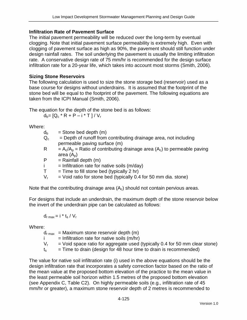
Infiltration Rate of Pavement Surface The initial pavement permeability will be reduced over the long-term by eventual clogging. Note that initial pavement surface permeability is extremely high. Even with clogging of pavement surface as high as 90%, the pavement should still function under design rainfall rates. The soil underlying the pavement is usually the limiting infiltration rate. A conservative design rate of 75 mm/hr is recommended for the design surface infiltration rate for a 20-year life, which takes into account most storms (Smith, 2006). Sizing Stone Reservoirs The following calculation is used to size the stone storage bed (reservoir) used as a base course for designs without underdrains. It is assumed that the footprint of the stone bed will be equal to the footprint of the pavement. The following equations are taken from the ICPI Manual (Smith, 2006). The equation for the depth of the stone bed is as follows:
db= [Qc * R + P – i * T ] / Vr Where:
db = Stone bed depth (m) Qc = Depth of runoff from contributing drainage area, not including
permeable paving surface (m) R = Ac/Ap = Ratio of contributing drainage area (Ac) to permeable paving
area (Ap) P = Rainfall depth (m) i = Infiltration rate for native soils (m/day) T = Time to fill stone bed (typically 2 hr) Vr = Void ratio for stone bed (typically 0.4 for 50 mm dia. stone)
Note that the contributing drainage area (Ac) should not contain pervious areas. For designs that include an underdrain, the maximum depth of the stone reservoir below the invert of the underdrain pipe can be calculated as follows:
dr max = i * ts / Vr
Where:
dr max = Maximum stone reservoir depth (m) i = Infiltration rate for native soils (m/hr) Vr = Void space ratio for aggregate used (typically 0.4 for 50 mm clear stone) ts = Time to drain (design for 48 hour time to drain is recommended)
The value for native soil infiltration rate (i) used in the above equations should be the design infiltration rate that incorporates a safety correction factor based on the ratio of the mean value at the proposed bottom elevation of the practice to the mean value in the least permeable soil horizon within 1.5 metres of the proposed bottom elevation (see Appendix C, Table C2). On highly permeable soils (e.g., infiltration rate of 45 mm/hr or greater), a maximum stone reservoir depth of 2 metres is recommended to

Low Impact Development Stormwater Management Planning and Design Guide
4-126 Version 1.0
prevent soil compaction and loss of permeability from the mass of overlying stone and stored water. If trying to size the area of permeable paving based on the contributing drainage area, the following equation may be used:
Ap = Qc * Ac / [Vr * dp – P + i * T] Alternatively, there is permeable pavement design software available on the market or from product manufacturers. Design Specifications Table 4.7.3 below gives specifications for pervious concrete, porous asphalt, and permeable pavers. Grid systems are not included due to the wide range in types and designs. For example, products using turf may specify a sand layer or no gravel storage area at all in order to maintain the vegetation health. The manufacturer should be consulted for the design specifications of their product. In pervious concrete and porous asphalt systems, the concrete or asphalt mix specifications and construction procedure are key to proper functioning. These systems require well trained and experienced contractors for installation.
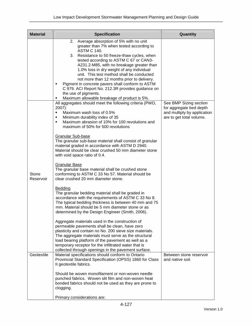
Table 4.7.3 Permeable pavement specifications
Material Specification Quantity
Pervious Concrete
� Schaefer et al. (2006) found that mix NO4-RG-S7 with air entrainment showed the best freeze-thaw durability after 300 freeze-thaw cycles.
� 28 day compressive strength = 5.5 to 20 MPa � Void ratio = 14% - 31% � Permeability = 900 to 21,500 mm/hr
Thickness will range from 100mm – 150 mm depending on the expected loads (NCPTC, 2006).
Porous Asphalt
� Open-graded asphalt mix with a minimum of 16% air voids
� Polymers can be added to provide additional strength for heavy loads
� The University of New Hampshire Stormwater Center has detailed design specifications for porous asphalt on their webpage: http://www.unh.edu/erg/cstev/pubs_specs_info
Thickness will range from 50 mm to 100 mm depending on the expected loads (NAPA 2008).
Permeable Pavers
� Permeable pavers should conform to manufacturer specifications.
� ASTM No. 8 (5 mm dia.) crushed aggregate is recommended for fill material in the paver openings. For narrow joints between interlocking shapes, a smaller sized aggregate may be used (Smith, 2006).
� Pavers shall meet the minimum material and physical properties set forth in CAN 3-A231.2, Standard Specification for Precast Concrete Pavers.
1. Average compressive strength 8000 psi (55MPa) with no individual unit under 7,250 psi (50MPa) in accordance with ASTM C396 or CAN3-A231.2-M85.
For vehicular applications, the minimum paver thickness is 80 mm and for pedestrian applications is 60 mm. Joint widths should be no greater than 15 mm for pedestrian applications.
Low Impact Development Stormwater Management Planning and Design Guide
4-127 Version 1.0
Material Specification Quantity
2. Average absorption of 5% with no unit greater than 7% when tested according to ASTM C 140.
3. Resistance to 50 freeze-thaw cycles, when tested according to ASTM C 67 or CAN3-A231.2-M85, with no breakage greater than 1.0% loss in dry weight of any individual unit. This test method shall be conducted not more than 12 months prior to delivery.
� Pigment in concrete pavers shall conform to ASTM C 979. ACI Report No. 212.3R provides guidance on the use of pigments.
� Maximum allowable breakage of product is 5%.
Stone Reservoir
All aggregates should meet the following criteria (PWD, 2007): � Maximum wash loss of 0.5% � Minimum durability index of 35 � Maximum abrasion of 10% for 100 revolutions and
maximum of 50% for 500 revolutions Granular Sub-base The granular sub-base material shall consist of granular material graded in accordance with ASTM D 2940. Material should be clear crushed 50 mm diameter stone with void space ratio of 0.4. Granular Base The granular base material shall be crushed stone conforming to ASTM C 33 No 57. Material should be clear crushed 20 mm diameter stone. Bedding The granular bedding material shall be graded in accordance with the requirements of ASTM C 33 No 8. The typical bedding thickness is between 40 mm and 75 mm. Material should be 5 mm diameter stone or as determined by the Design Engineer (Smith, 2006). Aggregate materials used in the construction of permeable pavements shall be clean, have zero plasticity and contain no No. 200 sieve size materials. The aggregate materials must serve as the structural load bearing platform of the pavement as well as a temporary receptor for the infiltrated water that is collected through openings in the pavement surface.
See BMP Sizing section for aggregate bed depth and multiply by application are to get total volume.
Geotextile Material specifications should conform to Ontario Provincial Standard Specification (OPSS) 1860 for Class II geotextile fabrics. Should be woven monofilament or non-woven needle punched fabrics. Woven slit film and non-woven heat bonded fabrics should not be used as they are prone to clogging. Primary considerations are:
Between stone reservoir and native soil.
Low Impact Development Stormwater Management Planning and Design Guide
4-128 Version 1.0
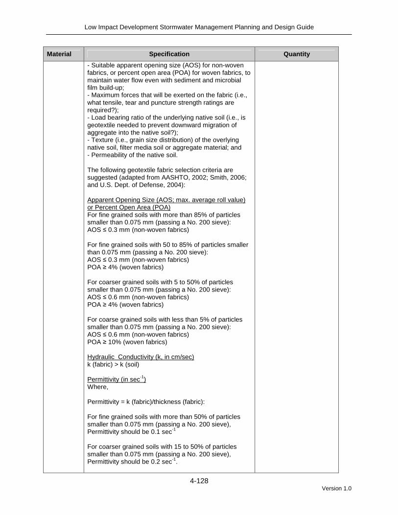
Material Specification Quantity
- Suitable apparent opening size (AOS) for non-woven fabrics, or percent open area (POA) for woven fabrics, to maintain water flow even with sediment and microbial film build-up; - Maximum forces that will be exerted on the fabric (i.e., what tensile, tear and puncture strength ratings are required?); - Load bearing ratio of the underlying native soil (i.e., is geotextile needed to prevent downward migration of aggregate into the native soil?); - Texture (i.e., grain size distribution) of the overlying native soil, filter media soil or aggregate material; and - Permeability of the native soil. The following geotextile fabric selection criteria are suggested (adapted from AASHTO, 2002; Smith, 2006; and U.S. Dept. of Defense, 2004): Apparent Opening Size (AOS; max. average roll value) or Percent Open Area (POA) For fine grained soils with more than 85% of particles smaller than 0.075 mm (passing a No. 200 sieve): AOS ≤ 0.3 mm (non-woven fabrics) For fine grained soils with 50 to 85% of particles smaller than 0.075 mm (passing a No. 200 sieve): AOS ≤ 0.3 mm (non-woven fabrics) POA ≥ 4% (woven fabrics) For coarser grained soils with 5 to 50% of particles smaller than 0.075 mm (passing a No. 200 sieve): AOS ≤ 0.6 mm (non-woven fabrics) POA ≥ 4% (woven fabrics) For coarse grained soils with less than 5% of particles smaller than 0.075 mm (passing a No. 200 sieve): AOS ≤ 0.6 mm (non-woven fabrics) POA ≥ 10% (woven fabrics) Hydraulic Conductivity (k, in cm/sec) k (fabric) > k (soil) Permittivity (in sec-1) Where, Permittivity = k (fabric)/thickness (fabric): For fine grained soils with more than 50% of particles smaller than 0.075 mm (passing a No. 200 sieve), Permittivity should be 0.1 sec-1 For coarser grained soils with 15 to 50% of particles smaller than 0.075 mm (passing a No. 200 sieve), Permittivity should be 0.2 sec-1.

Low Impact Development Stormwater Management Planning and Design Guide
4-129 Version 1.0
Material Specification Quantity
For coarse grained soil with less than 15% of particles smaller than 0.075 mm (passing a No. 200 sieve), Permittivity should be 0.5 sec-1.
Underdrain (optional)
� These pipes should be HDPE or equivalent material, continuously perforated and have a smooth interior with a minimum inside diameter of 100 mm.
� Perforations in pipes should be 10 mm in diameter (Smith, 2006).
� A standpipe from the underdrain to the pavement surface can be used for monitoring and maintenance of the underdrain. The top of the standpipe should be covered with a screw cap and vandal proof lock.
Pipes should terminate 0.3 m short from the sides of the base (Smith, 2006).
Construction Considerations Construction of permeable pavement is a specialized project and should involve experienced contractors. The following general recommendations apply:
� Sediment Control: The treatment area should be fully protected during construction so that no sediment reaches the permeable pavement system. Construction traffic should be blocked from the permeable pavement and its drainage areas once the pavement has been installed, and proper erosion and sediment controls must be maintained on site.
� Base Construction: For structural applications in parking lots, the stone
aggregate should be placed in 100 mm to 150 mm lifts and compacted with a minimum 9,070 kilograms (10 ton) steel drum roller. Stone materials should be moist during compaction. Equipment drivers are advised to avoid rapid acceleration, hard braking, and sharp turning on the compacted layers so that the base surfaces are not disturbed (Smith, 2006).
� Weather: Porous asphalt and pervious concrete will not properly pour and set in extremely high and low temperatures (City of Portland, 2004; U.S. EPA, 1999). One benefit to using permeable pavers is that their installation is not weather dependent.
� Pavement mix: Industry reps familiar with the porous pavement specifications
should be consulted for specifications on batching. Testing of concrete and asphalt materials on site is critical. Deviations from specified proportions and additives can result in an early failure of the pavement.
� Pavement placement: Properly installed permeable pavement requires trained
and experienced producers and construction contractors.
o Porous Asphalt uses the same equipment for mixing and laying as conventional asphalt (Figure 4.7.6). To avoid closing the pore spaces, compaction will use minimal pressure and the surface should not be smoothed or finished. The porous pavement will have a slightly rougher surface than conventional asphalt. The pavement should be allowed to set

Low Impact Development Stormwater Management Planning and Design Guide
4-130 Version 1.0
for 24 to 48 hours before vehicle or foot traffic is permitted (NAPA, 2008). o Pervious concrete has a low initial slump and fast set-times; meaning the
pavement will rapidly harden and mistakes are not easily corrected. Pervious concrete needs to be poured within one hour of mixing, but that time can be extended with the use of admixtures. Once poured, the concrete is leveled using a manual or mechanical screed set 13 mm above the finished height. To avoid closing off pore spaces, do not use floating and troweling. The concrete should be consolidated, typically with a steel roller, within 15 minutes of placement. Pervious concrete also requires a longer time to cure. The concrete requires a minimum of 7 days to cure and should be covered by plastic sheeting (NRMCA, 2008).
o Permeable Pavers can be placed by hand or some are designed to be
placed mechanically in segments to reduce labour costs (Figure 4.7.7). The main difference between laying conventional pavers and permeable pavers is the addition of the stone filler in the pore spaces. Most pavers are designed with the pore spaces built into their design or with nubs which provide an even spacing from the adjacent paver. The filler stone is swept over the pavement until all of the spaces are filled (Smith, 2006).
Figure 4.7.7 Examples of permeable pavement instal lations
Permeable pavers being mechanically placed in
sections (Source: CVC)
Porous asphalt installation (Source: Villanova
Urban Stormwater Partnership)
4.7.3 Maintenance and Construction Costs Inspection and Maintenance Like all other stormwater practices, permeable pavement requires regular inspection and maintenance to ensure that it functions properly. Well maintained permeable pavers are expected to last at least 20 years (e.g., Applied Research Associates, 2008). The limiting factor for permeable pavers is clogging within the aggregate layers, filler, or underdrain. The pavers themselves can be reused. Legally binding maintenance

Low Impact Development Stormwater Management Planning and Design Guide
4-131 Version 1.0
agreement which clearly specifies how to conduct routine maintenance tasks are essential for permeable pavement installed on private property. Ideally, signs should be posted on the site identifying permeable paver and porous pavement areas. This can also serve as a public awareness and education opportunity. The following maintenance procedures and preventative measures should be incorporated into a maintenance plan:
� Surface Sweeping: Sweeping should occur once or twice a year with a commercial vacuum sweeping unit to mitigate sediment accumulation and ensure continued porosity. Permeable pavement should not be washed with high pressure water systems or compressed air units, because they will push particles deeper into the pavement (PWD, 2007).
� Inlet Structures: Drainage pipes and structures within or draining to the subsurface bedding beneath porous pavement should be cleaned out on regular intervals (PWD, 2007).
� Heavy Vehicles: Trucks and other heavy vehicles can ground dirt into the porous surface and lead to clogging. These vehicles should be prevented from tracking or spilling dirt onto the pavement (PWD, 2007). Signage and training of facilities personnel is suggested.
� Construction and Hazardous Materials: Due to the potential for groundwater
contamination, all construction or hazardous material carriers should be prohibited from entering a permeable pavement site (PWD, 2007).
� Drainage Areas: Impervious areas contributing to the permeable pavement should be regularly swept and kept clear of litter and debris. Flows from any landscaped areas should be diverted away from the pavement or at least be well stabilized with vegetation.
� Grid Pavers: Paver or grid systems that have been planted with grass should be mowed regularly and the clippings should be removed (PWD, 2007). Water and fertilize as needed.
� Seal Coating: Seal coats should never be applied to permeable pavements.
Current and future owners and operations staff must be aware of permeable pavement areas and the importance of not applying any sealants. Porous asphalt and pervious concrete look very similar to their impervious versions and could be inadvertently sealed over.
� Potholes: For porous asphalt or pervious concrete, isolated potholes can be
patched with standard patching mixes. Patching can continue until the structural integrity of the pavement has been compromised or stormwater can no longer drain to the aggregate base. Then the surface will need to be torn up and replaced.
� Uneven Pavers: An uneven paver surface can be repaired by pulling up the

Low Impact Development Stormwater Management Planning and Design Guide
4-132 Version 1.0
pavers, redistributing the bedding layer, and then placing the pavers back. New filler stone will need to be swept into the replaced pavers. Typically the pavers are packed very tightly, and breaking one or more pavers will be necessary to pull up a group of pavers. Keeping a set of replacement pavers after construction will be useful for making future repairs.
� Weeds: Over time, weed growth may become a problem, particularly on surfaces
with infrequent traffic. Weeds can be an aesthetic issue and may also reduce the infiltration through the pavement. Keeping the pavement surface free of organic material through regular sweeping and vacuuming can impede weeds from taking root. Pulling weeds when they are small will limit damage to the pavement and loss of filler material between pavers. Ontario has banned the use of cosmetic herbicides.
� Winter Maintenance: Sand should not be spread on permeable pavement as it
can quickly lead to clogging. Deicers should only be used in moderation and only when needed because dissolved constituents are not removed by the pavement system. Pilot studies at the University of New Hampshire Stormwater Center have found that permeable pavement requires 75% less salt than conventional pavement over the course of a typical winter season (UNHSC, 2007).
� Snow Plowing: Permeable pavement is plowed for snow removal like any other
pavement (Figure 4.7.8). When groundwater contamination from chlorides is a concern, plowed snow piles and snow melt should not be directed to permeable paver and porous pavement systems (Smith, 2006).
Figure 4.7.8 Permeable pavement is plowed like any other pavement.
Source: ICPI
Annual inspections of permeable pavement should be conducted in the spring to ensure continued infiltration performance. These inspections should check for spilling or deterioration and test to whether water is draining between storms. The pavement reservoir should drain completely within 72 hours of the end of the storm event.

Low Impact Development Stormwater Management Planning and Design Guide
4-133 Version 1.0
Installation and Operation Costs Initial construction costs for permeable pavements are typically higher than conventional asphalt pavement surfaces, largely due to thicker aggregate base needed for stormwater storage. However, the cost difference is reduced or eliminated when total life-cycle costs, or the total cost to construct and maintain the pavement over its lifespan, are considered. Other savings and benefits may also be realized, including reduced need for storm sewer pipes and other stormwater practices, less developable land consumed for stormwater treatment, and ancillary benefits such as improved aesthetics and reduced urban heat island effect. These systems are especially cost effective in existing urban development where parking lot expansion is needed, but there is not sufficient space for other types of BMPs. They combine parking, stormwater infiltration, retention, and detention into one facility.
4.7.4 References American Association of State Highway and Transportation Officials (AASHTO). 2002. Geotextile Specification for Highway Applications. AASHTO M 288-00. Washington DC. Amrhein, C., Strong, J.E., and Mosher, P.A. 1992. Effect of de-icing salts on metal and organic matter mobilization in roadside soils. Environmental Science and Technology. Vol. 26, No. 4, pp. 703-709. Bauske, B., Goetz, D. 1993. Effects of de-icing salts on heavy metal mobility. Acta Hydrochimica Hydrobiologica. Vol. 21. pp. 38-42. Bean, E.Z., Hunt, W, F., Bidelspach, D.A. 2007a. Evaluation of Four Permeable Pavement Sites in Eastern North Carolina for Runoff Reduction and Water Quality Impacts. Journal of Irrigation and Drainage Engineering. Vol. 133. No. 6. pp. 583-592. Bean, E.Z., Hunt, W.F., Bidelspach, D.A. 2007b. Field survey of permeable pavement surface infiltration rates. Journal of Irrigation and Drainage Engineering. Vol. 133. No. 3. pp.249-255. Brattebo, B. and D. Booth. 2003. Long term stormwater quantity and quality performance of permeable pavement systems. Water Research 37(18): 4369-4376 Cahill Associates. 1993. Stormwater Management Systems: Porous Pavement with Underground Recharge Beds. West Chester, PA Center for Watershed Protection (CWP). 2007a. National Pollutant Removal Database – Version 3. September 2007. Ellicott City, MD. Center for Watershed Protection (CWP). 2007b. Urban Stormwater Retrofit Practices. Manual 3 in the Urban Subwatershed Restoration Manual Series. Ellicott City, MD.
Low Impact Development Stormwater Management Planning and Design Guide
4-134 Version 1.0
City of Portland. 2004. Portland Stormwater Management Manual. Prepared by the Bureau of Environmental Services (BES). Portland, OR. Collins, K., W. Hunt and J. Hathaway. 2008. Hydrologic comparison of four types of permeable pavement and standard asphalt in eastern North Carolina. Journal of Hydrologic Engineering. Ferguson, B.K. 2005. Porous Pavements. Integrative Studies in Water Management and Land Development. Taylor and Francis: New York. Gilbert, J. and J. Clausen. 2006. Stormwater runoff quality and quantity from asphalt, paver and crushed stone driveways in Connecticut. Water Research 40: 826-832. Granato, G.E., Church, P.E., Stone, V.J. 1995. Mobilization of Major and Trace Constituents of Highway Runoff in Groundwater Potentially Caused by De-icing Chemical Migration. Transportation Research Record. No. 1483. Greater Vancouver Regional District. 2005. Stormwater Source Control Design Guidelines 2005. Prepared by Lanarc Consultants Limited, Kerr Wood Leidal Associates Limited and Goya Ngan. Howard, K.W.F. and Beck, P.J. 1993. Hydrogeochemical implications of groundwater contamination by road de-icing chemicals. Journal of Contaminant Hydrology. Vol. 12. pp. 245-268. Hunt, W.F., Collins, K.A. 2008. Permeable Pavement: Research Update and Design Implications. North Carolina Cooperative Extension Service Bulletin. Urban Waterways Series. AGW-588-14. North Carolina State University. Raleigh, NC. James, W. 2002. Green Roads: Research into Permeable Pavers. Stormwater. March/April. Jefferies, C. 2004. Sustainable drainage systems in Scotland: the monitoring programme. Scottish Universities SUDS Monitoring Project. Dundee, Scotland Kwiatkowski, M., Welker, A.L., Traver, R.G., Vanacore, M., Ladd. T. 2007. Evaluation of an infiltration best management practice utilizing pervious concrete. Journal of the American Water Resources Association. Vol. 43. No. 5. pp. 1208-1222. Legret, M and V. Colandani. 1999. Effects of a porous pavement structure with a reservoir structure on runoff water: water quality and fate of metals. Water Science and Technology. 39(2): 111-117 Newman, A.P., S.J. Coupe, H.G. Smith, T. Puehmeier, and P. Bond. 2006. The Microbiology of Permeable Pavements. 8th International Conference on Concrete Block Paving, November 6-8, 2006, San Francisco, CA.

Low Impact Development Stormwater Management Planning and Design Guide
4-135 Version 1.0
National Asphalt Pavement Association (NAPA). 2008. Porous Asphalt Pavements for Stormwater Management: Design, Construction, and Maintenance Guide (IS-131). Lanham, MD. National Concrete Pavement Technology Center (NCPTC). 2006. Mix Design Developments for Pervious Concrete in Cold Weather Climates. Iowa State University. National Ready Mix Concrete Association (NRMCA). 2004. Freeze Thaw Resistance of Pervious Concrete. National Ready Mixed Concrete Association. Silver Spring, MD. National Ready Mix Concrete Association (NRMCA). 2008. Pervious Concrete: When it rains… it drains (website). Silver Spring, MD. http://www.perviouspavement.org/ Philadelphia Water Department (PWD). 2007. Philadelphia Stormwater Management Guidance Manual. Philadelphia, PA. Pitt, R., Clark, S. and Field, R. 1999. Groundwater contamination potential from stormwater infiltration. Urban Water. Vol. 1., pp. 217-236. Pratt, C.J., Mantle, J.D.G., Schofield, P.A. 1995. UK research into the performance of permeable pavement reservoir structures in controlling stormwater discharge quantity and quality. Water Science Technology. Vol. 32. No. 1. pp. 63-69. Roseen, R. 2007. LID Systems are Less Prone to Seasonal Performance Variations than Conventional Stormwater Management Systems. University of New Hampshire Stormwater Center. Schaefer, V.R., M.T. Sulleiman, K. Wang, J.T. Kevern, and P. Wiegand. 2006. An Overview of Pervious Concrete Applications in Stormwater Management and Pavement Systems. National Ready Mixed Concrete Association. 2006 Concrete Technology Forum. Schueler, T. 1987. Controlling urban runoff: a practical manual for planning and designing urban BMPs. Metropolitan Washington Council of Governments. Washington, DC. Smith, D. 2006. Permeable Interlocking Concrete Pavements; Selection, Design, Construction, Maintenance. 3rd Edition. Interlocking Concrete Pavement Institute. Burlington, ON. United States Environmental Protection Agency (U.S. EPA). 1999. Storm Water Technology Fact Sheet: Porous Pavement. EPA 832-F-99-023. University of New Hampshire Stormwater Center (UNHSC). 2009. UNHSC Design Specifications for Porous Asphalt Pavement and Infiltration Beds. Durham, NH.
Low Impact Development Stormwater Management Planning and Design Guide
4-136 Version 1.0
University of New Hampshire Stormwater Center (UNHSC). 2007. 2007 Annual Report. Durham, NH. Toronto and Region Conservation (TRCA). 2008b. Performance Evaluation of Permeable Pavement and a Bioretention Swale, Seneca College, King City, Ontario. Prepared under the Sustainable Technologies Evaluation Program (STEP). Toronto, Ontario. Toronto and Region Conservation (TRCA). 2009. Review of the Science and Practice of Stormwater Infiltration in Cold Climates. Prepared under the Sustainable Technologies Evaluation Program (STEP). Toronto, Ontario. United States Department of Defense. 2004. Unified Facilities Criteria: Engineering Use of Geotextiles.