46 class electric locomotives - sydney … description. the 46 class electric locomotives of which...
TRANSCRIPT
DEPARTMENT OF RAILWAYS : MECHANICALBRANCH
46 CLASSELECTRIC LOCOMOTIVES
Operating Instructions
F. P. HEARDCHIEF MECHANICAL ENGINEER
August, 1957.

Reprinted August 2003
HB 46OPER57.DOC

DEPARTMENT OF RAILWAYS : MECHANICALBRANCH
46 CLASSELECTRIC LOCOMOTIVES
Operating Instructions
F. P. HEARDCHIEF MECHANICAL ENGINEER
August, 1957.

FIG.1. SIDE VIEW.
C O N T E N T S.
PAGE:General Description:
General particulars .. .. .. .. 1 Cab .. .. .. .. .. .. .. .. 1 Bogies .. .. .. .. .. .. .. 2 Traction Motors .. .. .. .. .. 3 Control Equipment. .. .. .. .. 3 Brake Equipment .. .. .. .. .. 4 Performance .. .. .. .. .. .. 4
Equipment Details:
Wiring diagrams .. .. .. .. .. 5 Motor combinations .. .. .. .. 5 Master controller. .. .. .. .. 6 Main Isolating Switch. .. .. .. 7 Control Key Switch .. .. .. .. 8 Overload relays .. .. .. .. .. 8 Overvoltage relay. .. .. .. .. 9 Motor Generator control .. .. .. 9 Air compressor control .. .. .. 10 Pantograph control .. .. .. .. 10 Resistance fan control .. .. .. 12 Heaters .. .. .. .. .. .. .. 12 Motor cut out switch.. .. .. .. 13 Isolating cocks .. .. .. .. .. 13 Switches & circuit breakers .. .. 13
Preparation .. .. .. .. .. .. .. 16-22
Operation procedure:
Acceleration.. .. .. .. .. .. 22 Transition .. .. .. .. .. .. 23 Weak field .. .. .. .. .. .. 24 Running notches .. .. .. .. .. 24 Reversing. .. .. .. .. .. .. 24 Slipping.. .. .. .. .. .. .. 24 Reduction of speed .. .. .. .. 25 Section insulators .. .. .. .. 25

Page:
Regenerative Braking:
Speeds. .. .. .. .. .. .. .. 26 Loads.. .. .. .. .. .. .. .. 26 When to be used .. .. .. .. .. 27 Controller operation .. .. .. .. 27 Switching off.. .. .. .. .. .. 28 Change of combination.. .. .. .. 28 Connection with air brake.. .. .. 28 Wheel sliding.. .. .. .. .. .. 29 Loss of power.. .. .. .. .. .. 29 Over voltage protection .. .. .. 29 Start in series .. .. .. .. .. 30 Resistance in series .. .. .. .. 30
Pantographs. .. .. .. .. .. .. .. 31
Double heading.. .. .. .. .. .. .. 31
Amalgamation .. .. .. .. .. .. .. 32
Division .. .. .. .. .. .. .. .. 33
Stabling .. .. .. .. .. .. .. .. 35
Spare & emergency equipment. .. .. .. 36
Defects in operation:
Faults during preparation.. .. .. 38
Faults in running.. .. .. .. .. 40 Fan and M.G. Indicator light .. .. 41 Resistance fan inoperative. .. .. 42 Supply M.G. inoperative .. .. .. 42 Exciter M.G. inoperative .. .. .. 43 Compressor inoperative. .. .. .. 43 Overload relay tripping .. .. .. 43 Interruption of overhead supply .. 44
LOCATION OF ILLUSTRATIONS.
FacingFigure: Title: Page:
1 Side view Frontis piece 2 End view 1 3 Driving position 4 4 Driver’s switch panel 5 5 Pantograph valves and door interlocking 6 6 Door interlock bolt 7 7 H.T. Compartment No.1 end 8 8 Low tension panel No.2 end 9 9 Circuit breaker panel No.1 end 10 10 Compressor and governor 11 11 Pantograph & control and timing reservoirs 12 12 Pantograph three way cock, service position. 13 13 Pantograph three way cock, raising from storage reservoir. 14 14 Pantograph three way cock, charging position. 15 15 Machine compartment 16 16 Motor cut out switch and spare H.T. fuses. 17 17 Power connections End of book. 18 Sequence of contactors. " 19 Control circuits part I " 20 Control circuits part II " 21 Auxiliary control circuits " 22 Lighting and power point circuit. " 23 Brake piping " 24 Locomotive diagram "
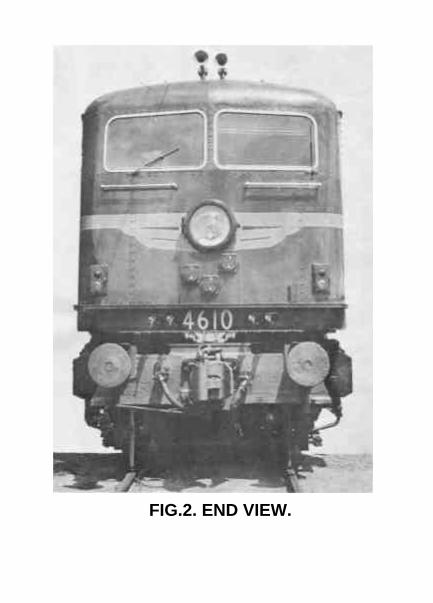
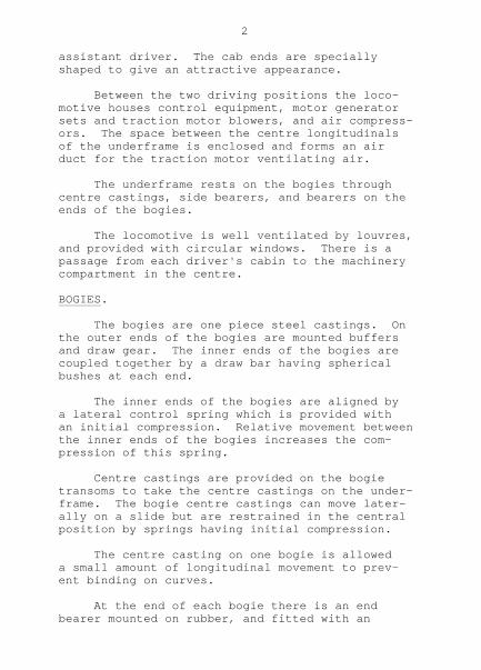
FIG.2. END VIEW.

GENERAL DESCRIPTION.
The 46 Class electric locomotives of which40 are on order in Great Britain are a develop-ment from 4501 which was built as a prototype.Both types of locomotives have the same wheelarrangement and maximum tractive effort, but the46 class has more powerful motors than the 45class, and can maintain its maximum tractiveeffort at higher speeds.
The locomotive is illustrated in figures 1and 2.
The driving position is illustrated infigure 3.
The 46 class electric locomotives will beused for hauling passenger and goods trains be-tween Sydney and Lithgow when the electrificationto Lithgow is completed in 1957.
General particulars are as follows:-
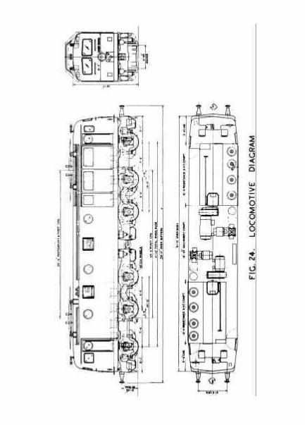
Voltage 1500 D.C.Wheel arrangement C + C.Mass 111 tons.Axle load 18.5 tonsWheel diameter 45 inchesBogie wheel base 14'0"Total wheel base 41'0"Length over buffers 54'0"Overall width 9'9"Height from rail level to pantograph, closed 14'6"Tractive effort at 25% adhesion 62,000 lbsTractive effort at the one hour rating 40,800 lbsSpeed at the one hour rating 34.5 mph.One hour rated horse power 3840Continuous horse power 3480Maximum speed 70 mph.Low tension supply 120 volts D.C.
CAB.
The cab has a driving position at each endwith comfortable accommodation for driver and
2
assistant driver. The cab ends are speciallyshaped to give an attractive appearance.
Between the two driving positions the loco-motive houses control equipment, motor generatorsets and traction motor blowers, and air compress-ors. The space between the centre longitudinalsof the underframe is enclosed and forms an airduct for the traction motor ventilating air.
The underframe rests on the bogies throughcentre castings, side bearers, and bearers on theends of the bogies.
The locomotive is well ventilated by louvres,and provided with circular windows. There is apassage from each driver's cabin to the machinerycompartment in the centre.
BOGIES.
The bogies are one piece steel castings. Onthe outer ends of the bogies are mounted buffersand draw gear. The inner ends of the bogies arecoupled together by a draw bar having sphericalbushes at each end.
The inner ends of the bogies are aligned bya lateral control spring which is provided withan initial compression. Relative movement betweenthe inner ends of the bogies increases the com-pression of this spring.
Centre castings are provided on the bogietransoms to take the centre castings on the under-frame. The bogie centre castings can move later-ally on a slide but are restrained in the centralposition by springs having initial compression.
The centre casting on one bogie is alloweda small amount of longitudinal movement to prev-ent binding on curves.
At the end of each bogie there is an endbearer mounted on rubber, and fitted with an
3
initial compression of the rubber. They alignthe bogies with the underframe and take the re-action caused by the tractive effort on thebogies. The springing on each side of each bogieis fully compensated. Each axle box is providedwith a laminated spring and two helical auxiliarysprings.
Axle boxes are of the single bearing selfaligning SKF roller type.
TRACTION MOTORS.
There are six traction motors per locomotive,each rated at 640 h.p. at the one hour rating, and580 h.p. continuously, at 725 volts. The motorshave six poles, and are lap wound.
Armature bearings are of the roller type andaxle suspension bearings are of the sleeve type.Pinions are of nickel chrome case hardening steel,and the gear wheel rims are of nickel chrome oilhardening steel. The gear wheel rims are mountedon the gear wheel centre through rubber bushes.
The traction motors are located laterally inthe bogies by rubber bushed links. This relievesthe ends of the suspension bearings of thrust.
The traction motor nose is mounted betweenrubber pads.
CONTROL EQUIPMENT.
The control equipment is arranged for themotors to be connected either six in series, twoparallel circuits each of 3 motors in series, orthree parallel circuits each of two motors inseries. Five weak field positions are providedin each combination. Contactors are of the elec-tro-pneumatic type.
Resistances are of strip metal type. Theyare provided with blowers which come into operat-ion when the resistances are in circuit for overa prescribed time.

FIG.3. DRIVING POSITION.

4
Provision is made for regenerative brakingin series and series-parallel.
The control voltage is 120 D.C.
There are two motor generator sets eachdriven by 1500 volt motors. One set includes a120 volts D.C. generator which provides power forlighting and control and for battery charging. Theother set includes a variable voltage generatorwhich is used for separately exciting the tractionmotor fields during regeneration.
Each motor generator set also drives a fanwhich discharges into the air duct between centrelongitudinals of the underframe and passes thenceto the traction motors. Each motor is blown with2500 cubic feet per minute.
The battery consists of 54 cells of the leadacid type with a capacity of 50 amp hours.
The two pantographs are of the double pantype. They are raised by air pressure controlledby electro-pneumatic valves operated from thedriver's position. A hand pump is provided for usein the absence of air pressure.
BRAKE EQUIPMENT.
There are two air compressors, each having adisplacement of 75 cubic feet per minute. Each isdriven by a 1500 volt motor.
Brake equipment is of the Australian Westing-house A-7-EL type. A diagram of the piping isshown in figure 23.
PERFORMANCE.
The locomotives are designed to haul 1100tons at 35 mph on the rising 1/90 grades betweenZig Zag and Newnes Junction, and 400 tons at 35mph on the rising 1/33 grades between ValleyHeights and Katoomba. Where grades and curvespermit they can haul passenger trains at 70 mph.

FIG.4. DRIVER'S SWITCH PANEL.

5
EQUIPMENT DETAILS.
WIRING DIAGRAMS.
Figure 17 shows the power connections.
Figure 18 shows the sequence of contactors.
Figure 19 shows part 1 of the control cir- cuits schematically.
Figure 20 shows part 2 of the control cir- cuits schematically.
Figure 21 shows the auxiliary control cir- cuits schematically.
Figure 22 shows the lighting and power point circuits schematically.
Figure 24 is a locomotive diagram, showing the leading dimensions.
MOTOR COMBINATIONS.
Each locomotive is equipped with six M.V.272traction motors which are axle mounted. MotorsNos. 1, 2 and 3 are on one bogie and motors Nos. 4,5 and 6 on the other bogie.
The motors can be connected in any of threespeed combinations by electro-pneumatic unitswitches:
(1) Series - six motors in series.
(2) Series-Parallel - two parallel circuits each of three motors in series.
(3) Parallel - three parallel circuits each of two motors in series.
In each combination resistance is first in-cluded in circuit with the motors. It is cut outby moving the accelerating handle of the mastercontroller from the off position to position No.20.

FIG.5. PANTOGRAPH VALVES & DOOR INTERLOCKING.
6
After all resistance has been cut out ineach combination there are five stages of weakfield.
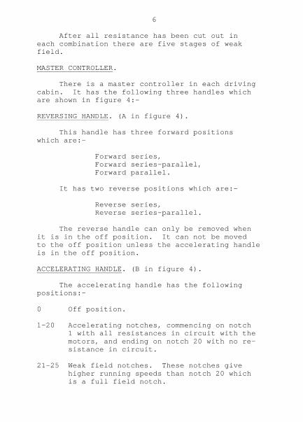
MASTER CONTROLLER.
There is a master controller in each drivingcabin. It has the following three handles whichare shown in figure 4:-
REVERSING HANDLE. (A in figure 4).
This handle has three forward positionswhich are:-
Forward series, Forward series-parallel, Forward parallel.
It has two reverse positions which are:-
Reverse series, Reverse series-parallel.
The reverse handle can only be removed whenit is in the off position. It can not be movedto the off position unless the accelerating handleis in the off position.
ACCELERATING HANDLE. (B in figure 4).
The accelerating handle has the followingpositions:-
0 Off position.
1-20 Accelerating notches, commencing on notch 1 with all resistances in circuit with the motors, and ending on notch 20 with no re- sistance in circuit.
21-25 Weak field notches. These notches give higher running speeds than notch 20 which is a full field notch.

FIG.6. DOOR INTERLOCK BOLT.
7
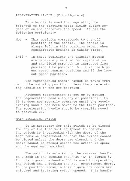
REGENERATING HANDLE. (C in figure 4).
This handle is used for regulating thestrength of the traction motor fields during re-generation and therefore the speed. It has thefollowing positions:-
Mot - This position corresponds to the off position of the handle. The handle is always left in this position except when regenerative braking is taking place.
1-15 - In these positions the traction motors are separately excited for regeneration and the field strength is increased from position 1 to position 15. 1 is the high- est speed running position and 15 the low- est speed position.
The regenerating handle cannot be moved fromor to the motoring position unless the accelerat-ing handle is in the off position.
Although regeneration is set up by movingthe regeneration handle to any of positions 1 to15 it does not actually commence until the accel-erating handle has been moved to the first position.The accelerating handle should be steadily movedto position 20.
MAIN ISOLATING SWITCH.
It is necessary for this switch to be closedfor any of the 1500 volt equipment to operate.The switch is interlocked with the doors of thehigh tension compartment so that the switch cannotbe closed unless the doors are closed, and thedoors cannot be opened unless the switch is open,and the equipment earthed.
The switch is unlocked by the reverser handleon a knob in the opening shown at "A" in figure 5.In this figure the handle "B" is used for operatingthe switch and unlocking the H.T. compartment doors.In the position shown in this figure the doors areunlocked and isolating switch opened. This handle

FIG.7. H.T. COMPARTMENT NO.1. END.
8
cannot be moved until the H.T. door interlock hasbeen freed by lowering the pantographs.
The projecting bolt shown at "A" in figure 6is operated by the handle "B" of figure 5.
CONTROL KEY SWITCH.
In order to obtain control current for thepantograph raise circuit, compressor control, andmaster controller it is necessary that the controlkey switch be closed. This switch is operated bythe same key that operates the driver's cabin door.It is important that when locomotives are coupledtogether, with the jumpers inserted, only one keyswitch should be closed on all locomotives.
The switch is illustrated in the "On" positionat "D" in figure 4.
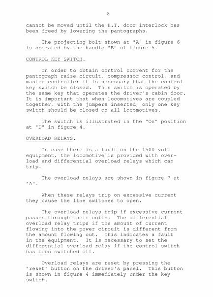
OVERLOAD RELAYS.
In case there is a fault on the 1500 voltequipment, the locomotive is provided with over-load and differential overload relays which cantrip.
The overload relays are shown in figure 7 at"A".
When these relays trip on excessive currentthey cause the line switches to open.
The overload relays trip if excessive currentpasses through their coils. The differentialoverload relay trips if the amount of currentflowing into the power circuit is different fromthe amount flowing out. This indicates a faultin the equipment. It is necessary to set thedifferential overload relay if the control switchhas been switched off.
Overload relays are reset by pressing the"reset" button on the driver's panel. This buttonis shown in figure 4 immediately under the keyswitch.

FIG.8. LOW TENSION PANEL NO.2. END.

9
They should not be reset more than twice insuccession. Repeated resetting would damage theequipment and might start a fire.
OVERVOLTAGE RELAY.
This relay is required during regenerationand opens the line switches if the voltage whichis being generated greatly exceeds the nominalline voltage. It is reset by pressing a pushbutton on the driver's switch panel. This button isshown in figure 4 below the overload reset button.
Neither the overload relays nor the over-voltage relays can be reset unless the accelerat-ing handle of the master controller is in the offposition.
MOTOR GENERATOR CONTROL SWITCHES.
While the locomotive is in service it isnecessary for both the motor generators to berunning to provide ventilating air for the tract-ion motors. Also the supply motor generator setmust be running to provide 120 volt control currentand keep the battery charged.
Each motor generator set is provided with ano current relay which makes contact if themachine is not running, and lights a yellow lampin each driver's cabin, as a warning to the driver.This lamp is shown at "E" in figure 4.
For the supply motor generator to be runningit is necessary that the miniature circuit breakerin the low tension switch board and the motor gen-erator two-way tumbler switch on one of the driv-er's desk panels should be closed.
The supply M.G. circuit breaker is No.1 infigure 8. The M.G. Tumbler switch is that labell-ed "motor generators" in figure 4.
For the exciter motor generator to be runn-ing it is necessary that its circuit breaker on

FIG.9. CIRCUIT BREAKER PANELNO.1. END.

10
the low tension switch panel should be closed andthe supply motor generator to be running.
The exciter M.G. circuit breaker is No.7 infigure 8.
AIR COMPRESSOR CONTROL.
For the air compressors to be running it isnecessary that the control key switch be "On",the circuit breaker controlling them on the lowtension switch panel and the compressor controlswitches on the same panel be closed. There is aseparate control switch for each compressor sothat either may be switched on while the other isidle. The normal operating condition is for bothcompressors to be switched on.
The compressor control circuit breaker isthat numbered 3 in figure 9 and the two switchesin the centre of this figure are the compressorcontrol switches.
There is a compressor governor in the com-pressor control circuit. When main reservoir airpressure is built up to the pressure at which thegovernor is set, normally 125 pounds per squareinch, the governor stops the operation of thecompressors. When the pressure has fallen to 105pounds per square inch the operation starts again.
The compressor governor is shown at "A" infigure 10.
PANTOGRAPH CONTROL.
The pantographs are raised by air pressureat 70 pounds per square inch from the pantographand control reservoir. After the locomotive hasbeen shut down for some time they are raised byair from the pantograph storage reservoir, or bya hand pump.
In the air supply from the pantograph andcontrol reservoir there is an isolating cockwhich is connected to the interlocking mechanism
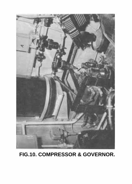
FIG.10. COMPRESSOR & GOVERNOR.

11
for the doors of the high tension compartments.This cock is enclosed in the H.T. Door interlockbox illustrated in figure 5. This prevents thepantographs being raised until the doors areclosed and locked. The air supply to the panto-graph also passes through a three-way cock,illustrated at "A" in figure 11. The threepositions of this cock are as follows:-
(1) In this position the handle is horizontal and the pantographs are connected via their electro-pneumatic pantograph valves to the pantograph air supply. This is the normal position of the cock while a locomotive is in service. See figure 12.
(2) In this position the handle points upwards and the pantographs are connected via their electro-pneumatic pantograph valves to the storage reservoir. In this position one of the pantographs can be raised from the storage reservoir by opening the storage reservoir wheel valve. See figure 13. The storage reservoir is shown at "A" in figure 15. This figure also shows the pantograph hand pump which must be used if the storage reservoir is depleted. The wheel valve is not shown in the figure but is to the right of the reservoir.
(3) In this position the handle is vertical pointing downwards. The storage reservoir is connected to the air supply so that it can be charged by opening its wheel valve. After charging, the wheel valve should be tightly closed to prevent loss of air. In this position the pantographs are lowered and isolated. See figure 14.
There are two pantograph electro-pneumaticvalves, one for the control of each pantograph.Each valve is operated by two push buttons, "up"and "down" in each driving cabin. All front orall rear pantographs can be operated together iflocomotives are coupled in multiple unit.

FIG.11. PANTOGRAPH & CONTROL ANDTIMING RESERVOIRS.
12
These pantograph valves are shown in figure5. This figure also shows the pantograph isolatingcocks. In this figure the cock for No.1 pantographis open, and that for No.2 pantograph is closed.The normal position is for both cocks to be open.
The pantograph push buttons are clearly shownto the left of the switch panel in figure 4.
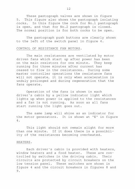
CONTROL OF RESISTANCE FAN MOTORS.
The main resistances are ventilated by motordriven fans which start up after power has beenon the main resistors for one minute. They keeprunning for three minutes after current hasceased to flow in the resistances. During somemaster controller operations the resistance fanswill not operate, it is only when acceleration isunduly prolonged and during regeneration that thefans operate.
Operation of the fans is shown in eachdriver's cabin by a yellow indicator light whichlights up when power is applied to the resistancesand a fan is not running. As soon as all fansstart running the light goes out.
The same lamp will shine as an indicator forthe motor generators. It is shown at "E" in figure4.
This light should not remain alight for morethan one minute. If it does there is a possibil-ity of the resistances becoming overheated.
HEATERS.
Each driver's cabin is provided with heaters,window heaters and a food heater. These are con-trolled by switches in the driving cabin. Theircircuits are protected by circuit breakers on thelow tension panel. These switches are shown infigure 4 and the circuit breakers in figures 8 and9.
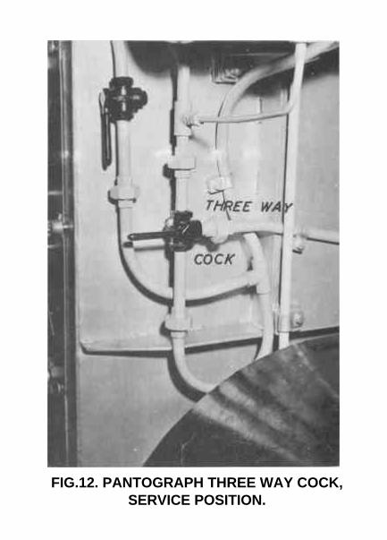
FIG.12. PANTOGRAPH THREE WAY COCK,SERVICE POSITION.

13
MOTOR CUT OUT SWITCH.
In case it is necessary to isolate a defect-ive motor a motor cut out switch is provided. Itis operated by the reverse handle of the mastercontroller. Either 1, 2 and 3 motors can be cutout together, or 4, 5 and 6 motors together, orall motors on the locomotive can be cut out. Thisswitch is shown in figure 16. It is in No.1H.T. Compartment.
ISOLATING COCKS.
The isolating cocks provided in each locomo-tive are listed below together with the correctrunning position of each cock.
Brake valve isolating cock at driving end openBrake valve isolating cock at non driving end closed.One compressor governor isolating cock open &) sealed)One main reservoir isolating cock openTwo pantograph isolating cocks openTwo pantograph & control reservoir isolating cocks inlet and outlet openThree-way pantograph cock handle horizontal (towards Corridor).One switchgroup isolating cock openOne time-delay reservoir isolating cock openOne sander isolating cock openOne distributing valve isolating cock open & sealed.One dead engine cock closedTwo brake cylinder isolating cocks openAll drain cocks closedHose coupling cocks not connected to adjacent locomotive closed.
SWITCHES AND CIRCUIT BREAKERS.
The various switches and miniature circuitbreakers are located as follows:-
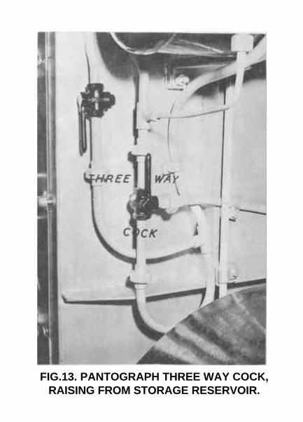
FIG.13. PANTOGRAPH THREE WAY COCK,RAISING FROM STORAGE RESERVOIR.

14
In No.1 H.T. Compartment.
Motor cut out switch. Main H.T. isolating switch. Compartment light switch.
In No.2 H.T. Compartment.
Compartment light switch.
In L.T. Cubicle (Back of No.2 Cab). (See figure 8.)
Battery isolating switch. 9 - Miniature circuit breakers (M.C.B's) for:- Voltage Regulator. Supply M.G. Head & Marker lights. Cab & Compartment lights. Corridor lights. Sanding. Locomotive Brake. Exciter M.G. Cab heaters.
In each driving cab.
Control key switch. ) Motor generator switch ) Headlight switch ) Pilot light switch. ) On driver's Instrument light switch ) switch panel. Food heater switch ) See figure 4. Cab heater switch ) Window heater switch ) Cab light switch ) Marker light switches )
In No.1 Cab only. (In cupboard on back wall). See figure 9.
Compressor switches. 6 - Miniature circuit breakers for:- Control main. Head and Marker lights. Compressor Control

FIG.14. PANTOGRAPH THREE WAY COCK,CHARGING POSITION.

15
Food heater Cab heater.
In Corridor. (Adjacent to each cab door).
Corridor light switch.
In Machinery Compartment. See figure 11.
8 - Resistance Fan M.C.B's (4 in each of two cupboards on H.T. Compt. walls).
Outside of locomotive.
4 - Handlamp socket switches (2 each side on underframe). 2 - Pantograph isolating switches (1 each end of roof).
To operate locomotive lights the battery iso-lating switch must be closed, together with thelighting M.C.B's. Individual groups of lights arethen controlled by their respective switches asrequired.

FIG.15. MACHINE COMPARTMENT.

16
PREPARATION AND STABLING.
1. In the event of any equipment being found "Cut out" unless labelled "Not to be used", or in the absence of a relevant entry in the Log Book, such equipment must be "Cut In".
2. If any authorised employee be at work on an electric locomotive at the time when the driver arrives to commence testing operat- ions, and if such work is likely to affect the electrical or air equipment, the driver must not proceed with the testing operations on the locomotive concerned, or cause the locomotive to be moved, until the work has been completed and all danger tablets removed from the departure end of the locomotive.
3. When an electric locomotive is stabled at a depot, the procedure outlined for stabling must be carried out by the stabling driver, unless instructed not to do so by the Shed Chargeman.
PREPARATION.
1. Obtain Driver's Daily Report Sheet, Reverser Key and Control Key. On arrival at Locomotive observe that both pantograph isolating switch- es are closed. Peruse Depot Officers Certi- ficate and commence preparation at No.2 end.
2. Enter cab and see that Hand Brake is "On" and locked. Check that all L.T. Circuit breakers are closed and place battery switch to "In" position. Switch on light to prove Battery fuses. Battery switch to be placed to "Out" position before L.T. fuses are renewed. See all switches on Driver's switch panel are up and "Off". Switch Cab and Corridor lights "On" if requi- red. See that Driver's Brake Valve Isolating Cock is closed. See that No.2 H.T. Compartment door is closed.

FIG.16. MOTOR CUT-OUT SWITCH ANDSPARE H.T. FUSES.

17
3. Pass through locomotive to No.1 end and unlock it. Check that all L.T. circuit breakers are closed and compressor switches are up and "Off". See all switches on Driver's switch panel are up and "Off". See Driver's Brake Valve isolating cock is closed. Open door of H.T. Compartment. See motor "Cut Out" switch in No.1 H.T. Com- partment is in "All in" or relative position as shown in Log Book. Check spare H.T. fuses and check that required H.T. fuses are in circuit. Close No.1 H.T. Compartment door.
4. Return to Machine (centre) compartment. Check that Fan resistance circuit breakers are Down and closed. Check spare equipment in compartment:- 3 Control Jumpers - A. B. & C. 2 Air hoses - brake pipe, main reservoir. 3 Bogie Hoses - Main reservoir, Brake cylinder, Sanding. 2 1/2" hose couplings. 1 Fire extinguisher. 1 Hook stick. Spare light globes:- 1 Head Light Globe 120V, 250 watt. 2 Interior " " 120V, 60 watt. 2 Marker " " 120V, 40 watt. 2 Pilot " " 120V, 15 watt. Check that seal is on the spare equipment locker. See that Main Reservoir, pantograph and con- trol reservoir, fan time delay reservoir, switch group, sanding relay, and pantograph isolating cocks are open and, that Main Res- ervoir to Distributing Valve Isolating Cock and Compressor Governor Isolating Cocks are both open and sealed. The Dead Engine cock must be closed, the handle pointing to the brake pipe connection on the distributing valve. Place the door locking lever down and lock H.T. switch with reverser key (two movements).

18
Enter No.l end cabin, insert control key in switch and switch "On". Press pantograph button to raise panto- graph and press button to lower leading pantograph. If main reservoir gauge shows 50 lbs. the pantograph can be raised with the three-way cock in "Horizontal" position. If main reservoir is less than 50 lbs place the three-way cock in "Up" position and open wheel valve of storage reservoir. If after opening wheel valve pantograph gauge shows less than 50 lbs and pantograph does not rise, close wheel valve and operate hand pump until pantograph makes good contact with the overhead wire. Proceed to No.1 end and note line voltage on volt meter and then switch on both compress- ors. Return to centre compartment and keep pump- ing until main reservoir pressure is 70 lbs. Then move three way cock to horizontal position and close wheel valve if not already closed.
5. Go to departure end. Then switch "On" supply generator. (Exciter Generator will start up automatically when Supply Generator is up to Speed). Check all spare equipment in departure end cabin including, fire extinguisher, hand lamp, red flags, detonators and "Tail Disc No.l end", "Spare L.T. fuses No.2 end". Test head, pilot, marker, gauge and interior lights and set required Head and Marker lights. Test whistle, windscreen wipers and raising and lowering operation of both pantographs. NOTE: Before lowering or raising pantographs the motor generators and compressors must be switched off.
Open Driver's Brake Valve isolating cock and test independent and automatic brake valves in the following manner:-
19
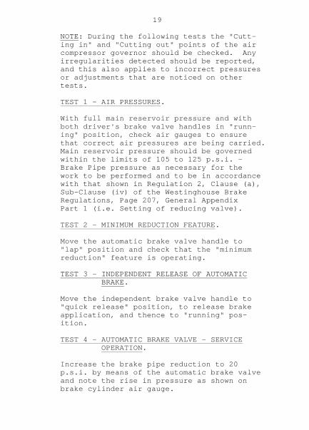
NOTE: During the following tests the "Cutt- ing in" and "Cutting out" points of the air compressor governor should be checked. Any irregularities detected should be reported, and this also applies to incorrect pressures or adjustments that are noticed on other tests.
TEST 1 - AIR PRESSURES.
With full main reservoir pressure and with both driver's brake valve handles in "runn- ing" position, check air gauges to ensure that correct air pressures are being carried. Main reservoir pressure should be governed within the limits of 105 to 125 p.s.i. - Brake Pipe pressure as necessary for the work to be performed and to be in accordance with that shown in Regulation 2, Clause (a), Sub-Clause (iv) of the Westinghouse Brake Regulations, Page 207, General Appendix Part 1 (i.e. Setting of reducing valve).
TEST 2 - MINIMUM REDUCTION FEATURE.
Move the automatic brake valve handle to "lap" position and check that the "minimum reduction" feature is operating.
TEST 3 - INDEPENDENT RELEASE OF AUTOMATIC BRAKE.
Move the independent brake valve handle to "quick release" position, to release brake application, and thence to "running" pos- ition.
TEST 4 - AUTOMATIC BRAKE VALVE - SERVICE OPERATION.
Increase the brake pipe reduction to 20 p.s.i. by means of the automatic brake valve and note the rise in pressure as shown on brake cylinder air gauge.

20
TEST 5 - REGENERATIVE INTERLOCK (a).
Before making the regenerative interlock test place the reverser key in forward series, press overload and overvoltage reset buttons, then place the accelerating handle in the first notch noting that a current reading is recorded on the ammeter. Return the accelerating handle and reverser key to the off position. With the auxiliary generator and the regenerative exciter runn- ing, reverser handle in forward series, place the regenerative handle in first pos- ition and with the accelerating handle also in the first notch, note that the air brake application releases.
TEST 6 - REGENERATIVE INTERLOCK (b).
Reduce the brake pipe pressure to zero, and check that the automatic control switch operates to cut out regenerative brake and that the air brake re-applies on the loco- motive. Return the accelerating handle to the "Off" position.
TEST 7 - FLOWMETER TEST.
Return the automatic brake valve handle to "running" position and note that one hand of the Flow Indicator Gauge momentarily drops towards zero and then returns to the normal fully charged position, overlapping other hand.
TEST 8 - INDEPENDENT APPLICATION WITH REGEN- ERATION.
Place the accelerating handle in the first notch. Move the independent brake valve handle to "slow" application position and check that a brake application is obtained and that the setting of the reducing valve (45 p.s.i.) is correct and leave handle in this position.

21
Move the accelerating handle to the "Off" position, the regenerative handle to "MOT", and reverser key to "Off" position.
TEST 9 - DISTRIBUTING VALVE SAFETY VALVE.
Reduce brake pipe pressure by 20 lbs. with the automatic brake valve handle in "service" Position and check that the distributing valve safety valve lifts when 55 p.s.i. brake cylinder pressure has been obtained. Release brakes by returning both brake valves to "running" position.
6. Move reverser key to either Forward or Rever- se Series position. Test Sanding device. Move Reverser key to "Off" position and remove key. Make application of the brakes in slow application position with Independent Driver's Brake Valve, close D.B.V. Isolating Cock and remove both D.B.V. handles. See that Hand Brake is applied and alight from cabin. Examine front of locomotive, checking all air cocks are closed and dummy couplers in correct position. See auto. coupler is in good order and jum- per receptacle lids properly closed.
7. Pass along "Off" side of locomotive. Examine brake shoes and riggings, springs etc. and see that Resistance Compartment doors are closed and securely fastened. Check that Air Brake Cut Out cocks are open, sand boxes full and working correct- ly and Brake piston travel between 3-1/2" and 5".
8. Enter rear end cabin and carry out instruc- tions as previously outlined in Clause 5. Note that air pressures indicated on the air gauges do not materially differ from those indicated at the other driving compartment.

22
Set required Tail lights and release Hand Brake if applied.
9. Examine rear and "On" side of Locomotive as outlined in clause 6 and 7.
10. Enter departure end cab. Open Driver's Brake Valve Isolating cock, release Hand Brake and lower leading Panto- graph if not required. Insert Reverser Key in Master Controller in readiness to depart.
11. Apply power in first notch "Forward" and "Reverse" and see that operation is correct.
NOTE: Blown H.T. fuses are to be placed in box provided in No.1 H.T. Compartment and blown L.T. fuses left in bottom of Battery Switch cupboard, No.2 cabin.
OPERATION PROCEDURE.
ACCELERATION IN SERIES.
To start a train or light engine the follow-ing actions are necessary:-
(1) The control key switch must be in the "On" position.(2) Place the reverser handle on the Master Con- troller and move it to series forward or reverse as required.(3) Press the overload reset button.(4) Release the brakes.
The accelerating handle can then be moved tothe first position and after a pause to the secondposition and so on.
If the locomotive is light it should move inthe first position. If on the other hand a heavytrain is attached it may be necessary to go to the6th or 7th position to get the train moving.
23
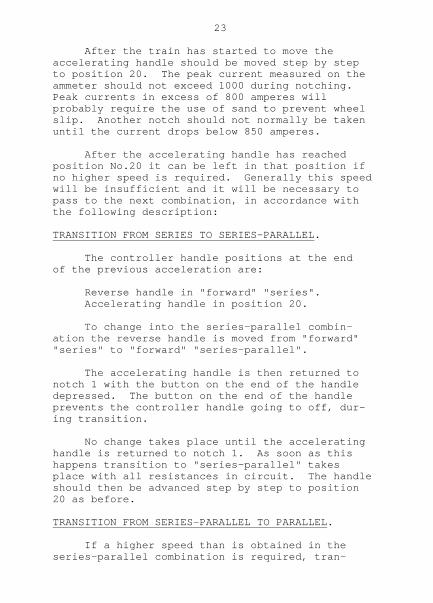
After the train has started to move theaccelerating handle should be moved step by stepto position 20. The peak current measured on theammeter should not exceed 1000 during notching.Peak currents in excess of 800 amperes willprobably require the use of sand to prevent wheelslip. Another notch should not normally be takenuntil the current drops below 850 amperes.
After the accelerating handle has reachedposition No.20 it can be left in that position ifno higher speed is required. Generally this speedwill be insufficient and it will be necessary topass to the next combination, in accordance withthe following description:
TRANSITION FROM SERIES TO SERIES-PARALLEL.
The controller handle positions at the endof the previous acceleration are:
Reverse handle in "forward" "series". Accelerating handle in position 20.
To change into the series-parallel combin-ation the reverse handle is moved from "forward""series" to "forward" "series-parallel".
The accelerating handle is then returned tonotch 1 with the button on the end of the handledepressed. The button on the end of the handleprevents the controller handle going to off, dur-ing transition.
No change takes place until the acceleratinghandle is returned to notch 1. As soon as thishappens transition to "series-parallel" takesplace with all resistances in circuit. The handleshould then be advanced step by step to position20 as before.
TRANSITION FROM SERIES-PARALLEL TO PARALLEL.
If a higher speed than is obtained in theseries-parallel combination is required, tran-

24
sition to parallel should be made. The reversehandle should be moved to "Forward" "parallel"position and the accelerating handle returned toNo.1 position. This will make the transition toparallel with all resistances in circuit. Theaccelerating handle should then be moved step bystep up to notch 20 as before.
WEAK FIELD NOTCHES.
There are five (5) positions of the accel-erating handle after notch 20. In these positionsthe fields of the traction motors are weakenedwhich increases the locomotive speed.
These notches should be used if a higherspeed than can be obtained in full field is re-quired, and if the next higher motor combinationwill give too high a speed.
Weak field notches should not be used at lessthan the speeds shown below:-
Combination: W.F.Notch. Minimum Speed.
Series 1 to 5 12 m.p.h.Series-parallel 1 to 3 22 m.p.h.Series-parallel 4 and 5 30 m.p.h.Parallel 1 to 3 35 m.p.h.Parallel 4 and 5 50 m.p.h.
RUNNING NOTCHES.
Positions 20 to 25 of the accelerating handleare running notches, and the handle may be leftcontinuously in any of these positions. It shouldnot be left continuously on any of positions 1to 19, as in these positions resistances are incircuit with the traction motors and they arenot designed for continuous operation. (Anexception to this instruction is given underseries regeneration).

25
REVERSING.
The reverser handle should never be thrownto reverse while the locomotive is moving forward,nor to forward while the locomotive is moving inreverse. The locomotive should be stopped beforea change in the direction of the reverser handleis made.
WHEELS SLIPPING.
Wheel slip relays operate a lamp and buzzer ineach driver's cabin if a wheel slip of over 7 m.p.h.occurs. The lamp and buzzer also operate duringtransition from series-parallel to parallel.
Wheel slips should be quickly corrected by theuse of sand and by the accelerating handle beingmoved back until the slip stops.
In weak field a slipping speed high enough toburst an armature can be attained if these notchesare used below a speed prescribed on page 24.
REDUCTION OF SPEED.
If on a rising grade it is necessary to re-duce speed, the accelerating handle should be re-turned slowly to the off position, the reversehandle should be moved to a lower speed combin-ation and the accelerating handle advanced tonotch 20.
SECTION INSULATIONS IN OVERHEAD WIRE.
Section insulators in the overhead wireseparate sections of the wire and there can bea difference of voltage between the two sides.
To reduce sparking at section insulatorswhenever practicable the locomotive should becoasted under them. Drivers should make a habitof switching off power while the pantographs arepassing under section insulators.

26
REGENERATIVE BRAKING.
During regeneration the power generated bythe motors is fed back to the overhead wire foruse by other trains.
Regenerative braking is available in theseries combination at speeds of approximately15 m.p.h. and upwards.
Maximum retardation is available at 15m.p.h., but above this speed the maximum amountof braking effort obtained falls off in inverseratio to the speed. For instance at 30 m.p.h.the maximum braking effort obtainable is onlyhalf that obtainable at 15 m.p.h.
Regenerative braking is also available inthe series-parallel combination at speeds of 30m.p.h. and upwards. In this case full brakingcan be obtained at 30 m.p.h. and the maximumbraking falls off in inverse ratio to the speed.
It should be noted that full brakingeffort can be obtained at only two speeds, name-ly 15 m.p.h. in series and 30 m.p.h. in series-parallel.
Operation at other speeds means a reductionin the amount of braking obtainable.
The maximum loads which can be braked at asteady speed on different grades without over-heating the traction motors, or danger of wheelsliding are as follows:-
Grade. Load which can be braked in series at 15 mph or series-parallel at 30 mph.
1/33 580 tons.1/40 760 tons.1/60 1250 tons.1/80 1850 tons.1/90 2150 tons.
27
WHEN REGENERATIVE BRAKING SHOULD BE USED.
The regenerative brake is designed to main-tain an approximately constant speed when descend-ing grades and it should be used for this purpose.If rapid deceleration or a stop is required theautomatic air brake should be used.
As the regenerative brake is applied onlyon the locomotive care must be taken to avoidsudden application or release which would imparta shock on the train.
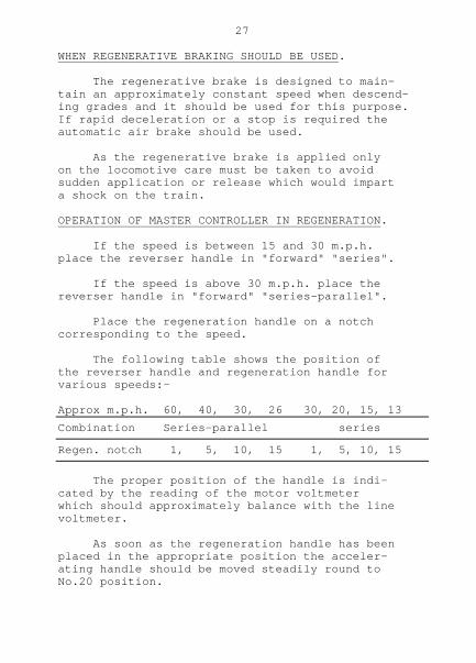
OPERATION OF MASTER CONTROLLER IN REGENERATION.
If the speed is between 15 and 30 m.p.h.place the reverser handle in "forward" "series".
If the speed is above 30 m.p.h. place thereverser handle in "forward" "series-parallel".
Place the regeneration handle on a notchcorresponding to the speed.
The following table shows the position ofthe reverser handle and regeneration handle forvarious speeds:-
Approx m.p.h. 60, 40, 30, 26 30, 20, 15, 13Combination Series-parallel series
Regen. notch 1, 5, 10, 15 1, 5, 10, 15
The proper position of the handle is indi-cated by the reading of the motor voltmeterwhich should approximately balance with the linevoltmeter.
As soon as the regeneration handle has beenplaced in the appropriate position the acceler-ating handle should be moved steadily round toNo.20 position.

28
The regeneration handle should then bemoved to suit the speed and braking effort re-quired. Movement of this handle should alwaysbe effected slowly.
Movement towards notch 15 increases brak-ing effort and movement in the opposite directiondecreases it.
TO SWITCH OFF.
When it is desired to switch off regener-ation the regeneration handle should be movedslowly until the armature current is zero. Theaccelerating handle should then be returned tothe off position. The regeneration handleshould then be returned to the motoring position.
If while regeneration is in operation it isnecessary to make a rapid decrease in speed, theautomatic air brake should be applied on the train.It is important that as soon as the armaturecurrent reads zero the accelerating handle shouldbe returned to the off position. Otherwise thelocomotive may take a motoring current.
CHANGE OF COMBINATION.
To change from series to series-parallel orvice versa in regeneration it is necessary toswitch off, adjust the speed of the train withthe air brake and commence regeneration again inthe new combination.
CONNECTION OF REGENERATION WITH AIR BRAKE.
As soon as the accelerating handle ismoved from the off position to commence regen-eration, a regeneration interlock magnet valve onthe distributing valve is energised. This enablesan automatic air brake application to be made onthe train without taking effect on the locomotive.
If, however, an emergency application ofthe automatic brake is made, the heavy reduction

29
of brake pipe pressure thus caused operates apneumatic switch which cuts off regeneration, andthereby, switches off the regeneration interlockmagnet valve, so that an emergency brake applicationis effective on the locomotive as well as on thetrain.
WHEEL SLIDING DURING REGENERATION.
The motor armature current should generallybe kept at less than 700 amperes to prevent wheelsliding during regeneration. If wheel slidingoccurs it is possible for the speed of the trainto increase rapidly, so a close watch on the speedshould be kept.
If wheel sliding occurs an immediate appli-cation of the automatic air brake should be madeto check the speed. This will reduce the brakingeffort being exerted by the locomotive and stopthe wheel sliding. At the same time the regener-ation handle should be moved to reduce the amountof braking.
LOSS OF OVERHEAD POWER.
If overhead power is lost while a train isdescending a steep grade an immediate applicationof the automatic air brake, sufficient to stopthe train, should be made, and this applicationmust not be released until power is restored andmain reservoir pressure exceeds 105 lbs persquare inch.
This instruction must be observed whetheror not regeneration is in operation, as it isessential that the brakes be applied before mainreservoir pressure has been depleted. The in-structions on page 259 of the General AppendixPart I apply.
OVER VOLTAGE PROTECTION.
If the voltage generated by the tractionmotors exceeds 2050 volts the overvoltage relaywill trip and cut off regeneration. Care should

30
be exercised in setting up regeneration not toallow the motor volts to greatly exceed the linevolts before connection is made to the line bymovement of the accelerating handle to notch 20.
If the overvoltage relay trips during regen-eration an automatic air brake application shouldbe made. The accelerating handle should be re-turned to the "off" position and the regeneratinghandle to the motoring position. The overvoltreset button should then be pressed after whichregeneration may be commenced again.
The line voltage should not be allowed toexceed 2000 volts. It can be reduced by reducingthe current regenerated, and if necessary usingthe automatic air brake to give the braking re-quired.
START IN SERIES REGENERATION.
A train may be started in series regenerationfrom rest if on a falling grade.
The regeneration handle should be placed innotch 2, and the accelerating handle advancednotch by notch to position 20, and the regener-ation handle adjusted as required.
The locomotive will take a motoring currentto start after which on a falling grade a brakingcurrent will be generated.
A start in series-parallel regeneration fromrest must not be made.
RESISTANCE IN SERIES REGENERATION.
In series regeneration the accelerating han-dle may be moved back as far as notch 12 to in-sert resistance in the motor circuit, this willallow of a slight increase in speed in this com-bination. This working does not apply to series-parallel regeneration.

31
PANTOGRAPHS.
Most wear on the overhead wire is caused bypassage of current to the pantograph stripsrather than by friction between wire and strips.It is therefore desirable at all times when haul-ing a train to operate with both pantographsraised. The current density at the pantographstrips is thereby kept as low as possible andthe rate of wear on the overhead wire kept aslow as possible.
When running light only the rear pantographshould be raised.
PANTOGRAPHS WHEN DOUBLE HEADED.
The overhead wire for the suburban area tothe east of Westmead is too light to allow forfour (4) pantographs being raised on two locomo-tives coupled together. Excessive lift of thecontact wire would occur and there would be poss-ible damage to pantographs at cross spans.
The overhead wire to the west of Westmeadis of heavier construction and allows four ad-jacent pantographs to be raised.
Double headed up trains passing throughWestmead must have the leading pantograph oneach locomotive lowered. The driver should dothis by first switching off power, then pressingthe pantograph "front" "Lower" button on the panelon the driver's desk.
DOUBLE HEADING.
When double heading it is the normal prac-tice for two locomotives to have jumpers insert-ed between them and for both machines to be con-trolled from the leading driving cabin.
Each locomotive is prepared as described inpreparation instructions.

32
Each locomotive carries three jumpers andtwo 1/2" hose couplings. One set of these fittingsshould be inserted at the point of coupling. Thecouplings for the 1/2" hose are duplicated on eachside, but a pair of hoses should be fitted on oneside only. The brake pipe and main reservoirhose pipes should be coupled. The hose pipecocks at each end of each hose pipe should beopened.
When uncoupling two locomotives the jump-ers and the 1/2" hose pipes removed from the pointof coupling should be placed in the locomotivenot equipped with these parts.
CONTROL AND BRAKE VALVE HANDLES.
When double heading the control key switch,reverser handle, automatic brake valve handle,and the independent brake valve handle should bein position on the appropriate equipment in theleading driver's cabin.
In the rear locomotive, the control key,and reverser handle should be removed from theequipment and placed on the bottom of the lowtension panel at No.2 End.
AMALGAMATION: DUTIES OF DRIVER & OBSERVER.
1. Observer: Secure the stationary locomotive or locomotives by applying the hand brakes un- less the stationary locomotive is attached to a train standing with brakes applied. Open the automatic coupler, signal the driver to ease up, and, when coupled, couple the main reservoir and train pipe hoses and open the four air cocks.
2. Driver: Obtain the three jumpers and two half inch air hoses from the hook in the passage- way of the locomotive, hand them down to the observer on the ground, and alight from the locomotive. Hand the jumpers ('B' jumper first) and the air hoses to the observer at
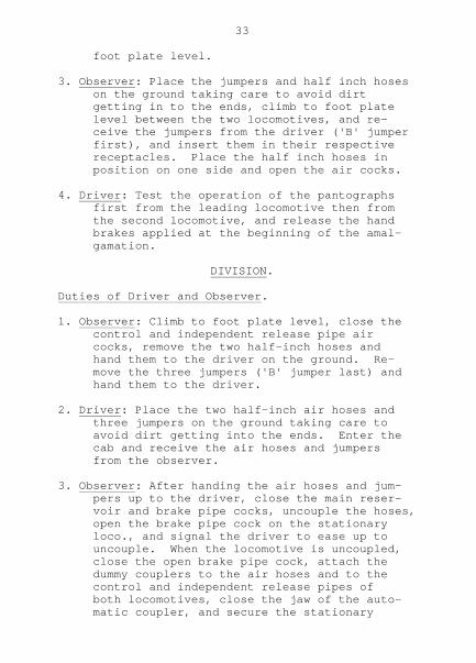
33
foot plate level.
3. Observer: Place the jumpers and half inch hoses on the ground taking care to avoid dirt getting in to the ends, climb to foot plate level between the two locomotives, and re- ceive the jumpers from the driver ('B' jumper first), and insert them in their respective receptacles. Place the half inch hoses in position on one side and open the air cocks.
4. Driver: Test the operation of the pantographs first from the leading locomotive then from the second locomotive, and release the hand brakes applied at the beginning of the amal- gamation.
DIVISION.
Duties of Driver and Observer.
l. Observer: Climb to foot plate level, close the control and independent release pipe air cocks, remove the two half-inch hoses and hand them to the driver on the ground. Re- move the three jumpers ('B' jumper last) and hand them to the driver.
2. Driver: Place the two half-inch air hoses and three jumpers on the ground taking care to avoid dirt getting into the ends. Enter the cab and receive the air hoses and jumpers from the observer.
3. Observer: After handing the air hoses and jum- pers up to the driver, close the main reser- voir and brake pipe cocks, uncouple the hoses, open the brake pipe cock on the stationary loco., and signal the driver to ease up to uncouple. When the locomotive is uncoupled, close the open brake pipe cock, attach the dummy couplers to the air hoses and to the control and independent release pipes of both locomotives, close the jaw of the auto- matic coupler, and secure the stationary

34
locomotive by applying the hand brakes.
4. Driver: When the locomotive is uncoupled, place the jumpers and air hoses on the hook in the passage-way of the locomotive not already equipped with these parts.

35
STABLING.
When the locomotive has been brought to astand at the point of stabling the followingduties should be carried out.
Close the driver's brake valve isolatingcock. Leave the automatic brake valve handle inthe running position and the independent brakevalve handle in the lap position.
Apply the leading hand brake hard on andlock it.
Switch off the supply motor generator atthe tumbler switch on the driver's desk.
Switch off compressors, heaters and lights.
Press both pantograph down buttons and lowerpantographs.
Check that the pantographs are down byvisual observation.
Turn pantograph three-way cock to the downposition, opening the storage reservoir wheelvalve and charging the storage reservoir. Closewheel valve tightly. Close the P & C reservoirinlet and outlet cocks.
Remove the control switch key and the rever-ser handle, walk around the locomotive and makesure there are no defective parts. Enter anydefects in the Log Book.
When leaving locomotive open battery switch,make sure that all doors are locked and windowsclosed.

36
DRIVERS, SPARE AND EMERGENCY EQUIPMENT.
The following equipment shall be carried ineach 46 class electric locomotive:-
DRIVER'S EQUIPMENT.
2 Hand lamps. One in each driver's cabin. 1 Tail disc. In No.1 cabin. 2 cases of 12 detonators. One in each cabin. 2 red flags (in flag cases). One in each cabin.
FOR COUPLING TO ANOTHER LOCOMOTIVE.
2 1/2" hose couplings. In No.2 End Corridor 3 Jumper couplings. In No.2 End Corridor.
TOOLS.
1 Spanner, hose M.R.& T.L. ) 1 " " Bogie M.R. ) 1 " " " B.Cyl.) 1 " " " Sand )In sealed box in 1 Pin punch 3/8" )No.1 end corridor. 1 Chisel ) 1 Hammer ) 1 Spanner, fuse. ) 1 Inspection light & lead )
SPARE AND EMERGENCY EQUIPMENT.
1 Air hose M.R. 3/4" ) 1 " " T.L. 1" ) 1 " " B.Cyl 1" ) 1 " " Sand 1/2" )In open box in 1 Rope 40 ft. )No.1 end 1 Light globe, headlight 250W.)corridor. 1 " " interior 60W.) 1 " " marker 40W.) 1 " " pilot 15W.) 2 Fuses, Main Aux. H.T. 150A In rack in No.1 H.T. Compt. 2 " Gen H.T. 50A In rack in No.1 H.T. Compt.

37
2 Fuses, Comp. H.T. 18A In rack in No.1 H.T. Compt. 1 " Voltmeter 9.5A In rack in No.1 H.T. Compt. 2 " L.T. Gen & Battery 100A On bottom of L.T. Panel No.2 end.
Spent H.T. fuses to be placed in box in No.1 H.T. Compartment.
Spent L.T. fuses to be placed in bottom of No.2 L.T. Panel.
1 Hook stick. In No.1 end corridor. 3 Fire Extinguishers. One in each cabin and centre compartment.

38
DEFECTS IN OPERATION.
The following are hints to assist in over-coming operating troubles which may be experienced.
FAULTS DURING PREPARATION.
1. Lights will not go on when M.G. is not running.
a) Check that Battery isolating switch is closed. b) Check that miniature circuit breakers (MCB) are "On". c) Check Battery Fuses.
2. Pantograph will not go up.
a) Check that H.T. doors are closed and com- pletely locked. b) Check Control key switch is "On". c) Check that amber light on desk is showing.
If not - Check that the lights work (See 1). Check that "Control Main" M.C.B. is on. Check that "Control" M.C.B. is on. d) Check that correct air pressure is avail- able. e) Check that pantograph isolating cocks are open.
3. Line Voltmeters do not register.
a) Check that pantograph is up (See 2). b) Check that roof switches are closed. c) Check voltmeter fuses (9.5 amps).
4. Compressors will not start.
a) Check control key switch is "On". b) Check Voltmeter is reading (See 3).
If motor generators are not running, and amber light is not showing, then:-

39
c) Check ( i) that lights work (See 1). ( ii) "Control Main" M.C.B. is "On". (iii) "Control" M.C.B. is "On" d) Check "Compressors" M.C.B. is "On". e) Check 18 Amp. Compressor fuses. f) Check 160 Amp. Main H.T. Auxiliaries fuse. If one compressor only will not start, (i) Check 18 Amp Compressor fuses.
NOTE: The Compressors will not start if main Reservoir pressure is above 105 p.s.i. gauge.
5. Motor Generators will not start.
a) Check that Compressors will start (See 4). b) Check that ( i) "Supply M.G." M.C.B. is "On". (ii) "Exciter M.G." M.C.B. is "On". c) Check Switchgroup isolating cock is open. d) Check 50 Amp Supply M.G. H.T. Fuse.
6. Exciter M.G. set only will not start.
a) Check that "Exciter M.G." M.C.B. is "On".
7. Cab, Food and Window Heaters.
a) Check that M.G. Sets are running, as other- wise heaters are not available. b) Check the appropriate M.C.B.s.
8. Sanders will not operate.
a) Check that "Sander" M.C.B. is "On". b) Check that Sander Isolating Cock is open.
9. Horns will not operate.
If main reservoir pressure is available, horns are defective.
40
FAULTS IN RUNNING.
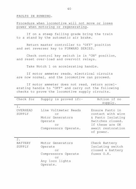
Procedure when locomotive will not move or losespower when motoring or regenerating.
If on a steep falling grade bring the trainto a stand by the automatic air brake.
Return master controller to "Off" positionand set reverser key to FORWARD SERIES.
Check control key switch is in "ON" position,and reset over-load and overvolt relays.
Take Notch 1 on accelerating handle.
If motor ammeter reads, electrical circuitsare now normal, and the locomotive can proceed.
If motor ammeter does not read, return accel-erating handle to "OFF" and carry out the followingchecks to prove the locomotive supply circuits.
Check for Supply is proved if:- Action if nosupply.
1.OVERHEADSUPPLY
Line Voltmeter Reads orMotor GeneratorsOperate orCompressors Operate.
Ensure Panto incontact with wire& Panto IsolatingSwitches closed.If these are OKawait restorationof power.
2.BATTERYSUPPLY
Motor GeneratorsOperate orCompressors Operate orAny loco lightsOperate.
Check BatteryIsolating switchclosed & batteryfuses O.K.

41
Check for Supply is proved if:- Action if nosupply.
3.CONTROLCIRCUITSUPPLY
Compressors Operate orUnit switchesOperate orIndicator Lamps Light.
Check Main andControl M.C.B's.
4.CONTROLAIRSUPPLY
Motor GeneratorsOperate orAny Unit switchOperates.
Check all Isol-ating cocks onP & C Reservoirand Switch-group.
RESISTANCE FANS AND MOTOR GENERATORS INDICATORLIGHTS.
There is an indicator lamp on each driver'spanel for the resistance fan motors and for themotor generators. If this lamp is alight it in-dicates either that one of the motor generatorshas stopped, or that one of the resistance fanshas stopped. If the lamp is alight when theaccelerating handle is in the off position theindication is that one of the motor generatorshas stopped.
When double headed the indicator light showswhether a resistance fan or a motor generator oneither locomotive is not operating.
When the accelerating handle is on notches1 to 19 the lamp will normally light and stayalight for approximately one minute.
If it remains alight for more than oneminute there is indication of trouble with theresistance fan motors or one of the motor gener-ators. In this case:-

42
Check that both motor generators are running.Check that all eight fan circuits breakers onthe low tension panels in the centre compartmentare closed.
RESISTANCE FAN INOPERATIVE.
If both motor generators are running it isprobable that one or more of the fan motors hasstopped, and repeated accelerations will over-heat the resistances.
Resistance should not be inserted duringseries regeneration.
The resistances are designed to stand twosuccessive starts each taking five minutes with-out the fans operating.
If the fans are not operating and additionalstarts are required it may be necessary to waitfor the resistances to cool down.
SUPPLY M.G. INOPERATIVE.
If the supply motor generator is inoperative,the ventilating air to the traction motors isgreatly reduced and care must be taken to avoidoverheating the motors. In such conditions theaverage motor currents must not exceed the follow-ing values:
700 amps for 30 minutes. 550 amps for 60 minutes. 450 amps for continuously.
If the load is such that the current exceedsthese values the train must be placed in the firstsiding to avoid damage to the motors, and thelocomotive worked light to a depot.
The regenerative brake and the resistance fansare inoperative.
43
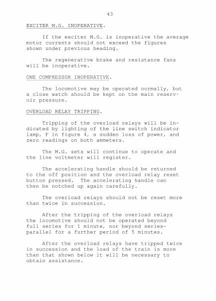
EXCITER M.G. INOPERATIVE.
If the exciter M.G. is inoperative the averagemotor currents should not exceed the figuresshown under previous heading.
The regenerative brake and resistance fanswill be inoperative.
ONE COMPRESSOR INOPERATIVE.
The locomotive may be operated normally, buta close watch should be kept on the main reserv-oir pressure.
OVERLOAD RELAY TRIPPING.
Tripping of the overload relays will be in-dicated by lighting of the line switch indicatorlamp, F in figure 4, a sudden loss of power, andzero readings on both ammeters.
The M.G. sets will continue to operate andthe line voltmeter will register.
The accelerating handle should be returnedto the off position and the overload relay resetbutton pressed. The accelerating handle canthen be notched up again carefully.
The overload relays should not be reset morethan twice in succession.
After the tripping of the overload relaysthe locomotive should not be operated beyondfull series for 1 minute, nor beyond series-parallel for a further period of 5 minutes.
After the overload relays have tripped twicein succession and the load of the train is morethan that shown below it will be necessary toobtain assistance.
44
GRADE. LOAD.
1/33 175 tons 1/40 250 tons 1/60 350 tons 1/90 550 tons
If the load is less than that shown, Nos.12 and 3 motors should be cut out by setting themotor cut out switch to "1, 2 & 3 OUT". The over-load relays should be reset, the reverser handlemoved to series-parallel, and an attempt made toproceed in this combination.
Only the series-parallel position is effectivewith motors cut out. Regenerative braking isinoperative. The line switch indicator lamp isinoperative with motors cut out.
If the overload relays trip again, Nos.1, 2and 3 motors should be cut in and 4, 5 and 6motors cut out. The overload relays should bereset again and an attempt made to proceed inseries-parallel.
If the overload relays trip again the loco-motive is a total failure.
When double headed the line switch indicatorlamp shows whether the overload relays have tripp-ed on either locomotive.
INTERRUPTION OF OVERHEAD SUPPLY.
This will be shown by loss of indication onthe line voltmeter. The line switches will openthrough the action of the no current relay whichis de-energised on loss of line voltage.
Return the accelerating handle to the "OFF"position and when power is restored, as indicatedby the line voltmeter, and main reservoir airpressure has been restored, notch up again in thenormal manner.