4.5k upper cold box shear key calculations · a separate analysis by hdr verifies the ucb anchor...
TRANSCRIPT

Engineering Calculation
Document Title: 4.5K Upper Cold Box Shear Key Calculations
Document Number: 79221-A0002 R- Page 1 of 18
4.5K Upper Cold Box
Shear Key Calculations
Document Approval: Date Approved
Originator: Scott Kaminski, Mechanical Engineer LCLS-II 02/01/17
Checker: Chase Dubbe, JLab Mechanical Design Engineer 02/01/17
Approver: Michael Bevins, JLab Cryogenics Plant Deputy Control Account Manager 02/01/17
Issued for Project Use
History
Revision Date Released Description of Change
- February 01, 2017 Original release, Issued for Project use
Approved: 2/1/2017; E-Sign ID : 336975; signed by: DCG: T. Fuell; Re. 1: C. Dubbe; Re. 2: M. Bevins |

Engineering Calculation
Document Title: 4.5K Upper Cold Box Shear Key Calculations
Document Number: 79221-A0002 R- Page 2 of 18
1.0 Introduction .................................................................................................................................. 3
2.0 Shear Key Design ......................................................................................................................... 4
3.0 Design Basis ................................................................................................................................. 6
4.0 Concrete Bearing .......................................................................................................................... 9
5.0 Shear Key ................................................................................................................................... 10
6.0 Attachment Weld ........................................................................................................................ 11
7.0 Summary / Conclusions .............................................................................................................. 13
8.0 References .................................................................................................................................. 13
Appendix A – UCB Reaction Shear Forces ...................................................................................... 14
Approved: 2/1/2017; E-Sign ID : 336975; signed by: DCG: T. Fuell; Re. 1: C. Dubbe; Re. 2: M. Bevins |
Engineering Calculation
Document Title: 4.5K Upper Cold Box Shear Key Calculations
Document Number: 79221-A0002 R- Page 3 of 18
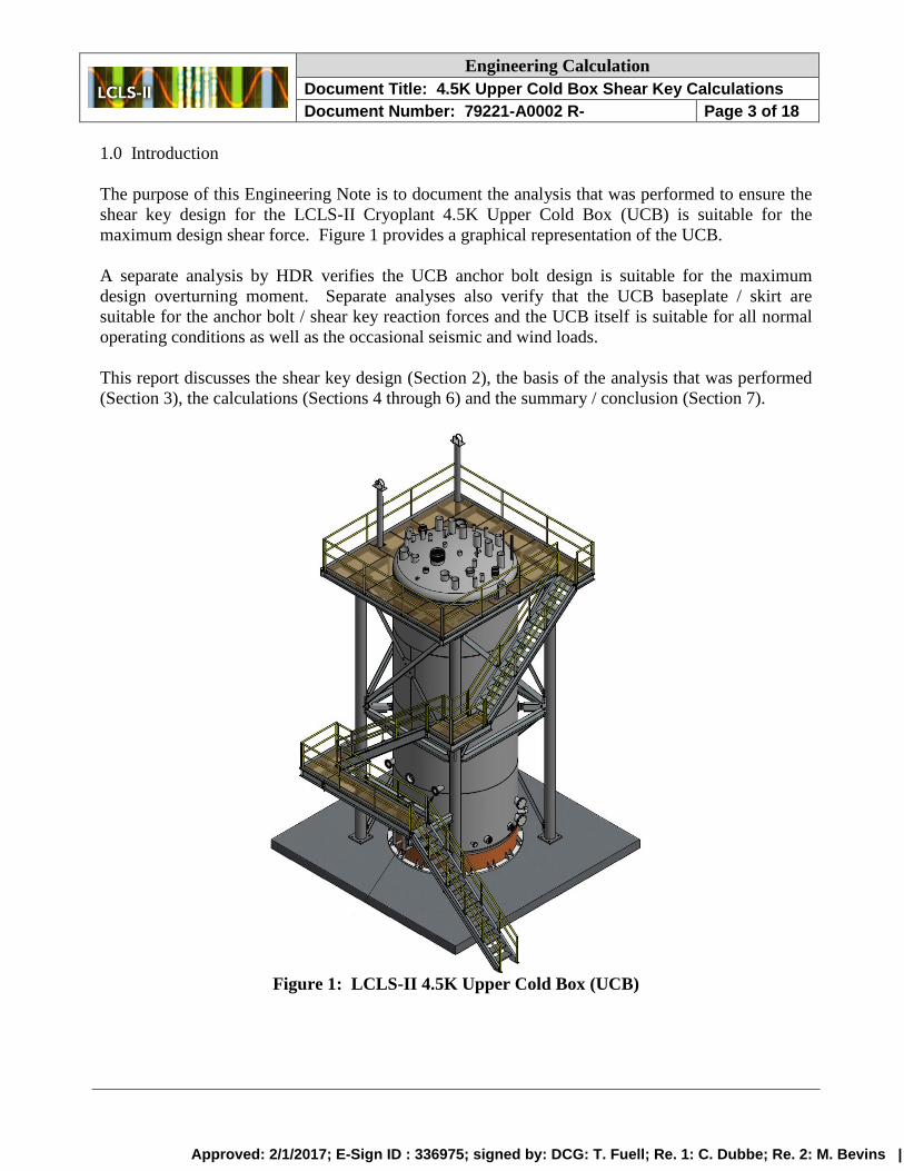
1.0 Introduction
The purpose of this Engineering Note is to document the analysis that was performed to ensure the
shear key design for the LCLS-II Cryoplant 4.5K Upper Cold Box (UCB) is suitable for the
maximum design shear force. Figure 1 provides a graphical representation of the UCB.
A separate analysis by HDR verifies the UCB anchor bolt design is suitable for the maximum
design overturning moment. Separate analyses also verify that the UCB baseplate / skirt are
suitable for the anchor bolt / shear key reaction forces and the UCB itself is suitable for all normal
operating conditions as well as the occasional seismic and wind loads.
This report discusses the shear key design (Section 2), the basis of the analysis that was performed
(Section 3), the calculations (Sections 4 through 6) and the summary / conclusion (Section 7).
Figure 1: LCLS-II 4.5K Upper Cold Box (UCB)
Approved: 2/1/2017; E-Sign ID : 336975; signed by: DCG: T. Fuell; Re. 1: C. Dubbe; Re. 2: M. Bevins |
Engineering Calculation
Document Title: 4.5K Upper Cold Box Shear Key Calculations
Document Number: 79221-A0002 R- Page 4 of 18
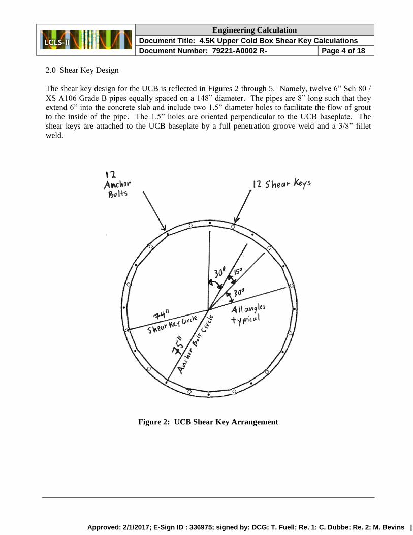
2.0 Shear Key Design
The shear key design for the UCB is reflected in Figures 2 through 5. Namely, twelve 6” Sch 80 /
XS A106 Grade B pipes equally spaced on a 148” diameter. The pipes are 8” long such that they
extend 6” into the concrete slab and include two 1.5” diameter holes to facilitate the flow of grout
to the inside of the pipe. The 1.5” holes are oriented perpendicular to the UCB baseplate. The
shear keys are attached to the UCB baseplate by a full penetration groove weld and a 3/8” fillet
weld.
Figure 2: UCB Shear Key Arrangement
Approved: 2/1/2017; E-Sign ID : 336975; signed by: DCG: T. Fuell; Re. 1: C. Dubbe; Re. 2: M. Bevins |

Engineering Calculation
Document Title: 4.5K Upper Cold Box Shear Key Calculations
Document Number: 79221-A0002 R- Page 5 of 18
Figure 3: UCB Shear Key Design
Figure 4: Shear Key in Concrete Top View
Approved: 2/1/2017; E-Sign ID : 336975; signed by: DCG: T. Fuell; Re. 1: C. Dubbe; Re. 2: M. Bevins |

Engineering Calculation
Document Title: 4.5K Upper Cold Box Shear Key Calculations
Document Number: 79221-A0002 R- Page 6 of 18
Figure 5: Shear Key in Concrete Section View
3.0 Design Basis
The applied seismic loads and load combinations are specified in the 2013 California Building
Code (CBC) [1] and its reference standard ASCE 7-10 [2].
Per the LCLS-II Cryogenic Building Geotechnical Report [3] and the Cryogenic Plant Seismic
Design Criteria [4], the site seismic design parameters include Site Class C, SD1 = 1.012 and SDS =
1.968.
The substances used in the LCLS-II Cryoplant and the UCB (namely inert cryogenics, gaseous /
liquid helium and gaseous / liquid nitrogen) are not hazardous (highly toxic or explosive /
flammable) in accordance with CBC Table 307.1 and the Cryogenic Plant Seismic Design Criteria.
Thus, per ASCE 7-10 Table 1.5-1 and the Cryogenic Plant Seismic Design Criteria, the Risk
Category for the Cryogenic Building and its associated components is II. Per ASCE 7-10 Table
1.5-2 and the Cryogenic Plant Seismic Design Criteria, the Seismic Importance Factor for the
Cryogenic Building and its associated components is Ie = 1.0. Per ASCE 7-10 11.6 and the site
seismic design parameters (S1 = 1.168), the Seismic Design Category for the Cryogenic Building
and its associated components is E.
Approved: 2/1/2017; E-Sign ID : 336975; signed by: DCG: T. Fuell; Re. 1: C. Dubbe; Re. 2: M. Bevins |

Engineering Calculation
Document Title: 4.5K Upper Cold Box Shear Key Calculations
Document Number: 79221-A0002 R- Page 7 of 18
As the UCB is a self-supporting structure that carries gravity loads and is required to resist the
effects of an earthquake, it is classified as a non-building structure in ASCE 7-10. As the structural
assessment of the UCB includes confirmation that the maximum buckling stress with Ie/R = 1.0 is
less than the critical buckling stress, the UCB is considered a welded steel skirt-supported vertical
vessel with special detailing in accordance with ASCE 7-10 Table 15.4-2. Since Option 2 in the
Cryogenic Plant Seismic Design Criteria applies to the UCB, the Response Modification Factor in
ASCE 7-10 is reduced by a factor two. Thus R = 3 / 2 = 1.5 for design of the UCB shear keys.
The seismic base shear applied to the UCB shear keys is determined in accordance with ASCE 7-10
12.8 and 15.4.1 as demonstrated below.
• 𝑉 =𝑆𝐷𝑆
𝑅
𝐼𝑒
𝑊 =1.968
1.5
1
𝑊 = 1.312 𝑊 (12.8-1, 2)
• 𝑉𝑚𝑎𝑥 =𝑆𝐷𝑆
𝑇𝑅
𝐼𝑒
𝑊 =1.968
0.27 1.5
1
𝑊 = 4.860 𝑊 (12.8-3)
• where 𝑇 = 𝑇𝑎~0.02 (388/12).75 = .27 (12.8.2, 12.8-7)
• 𝑉𝑚𝑖𝑛 = 0.044 𝑆𝐷𝑆𝐼𝑒 𝑊 = .044(1.968)(1)𝑊 = .087 𝑊 (15.4-1)
• 𝑉𝑚𝑖𝑛 = 0.8 𝑆1/(𝑅/𝐼𝑒) 𝑊 = 0.8 (1.168)
1.5
1
𝑊 = .623 𝑊 (15.4-2)
• So, 𝑉 = 1.312 𝑊
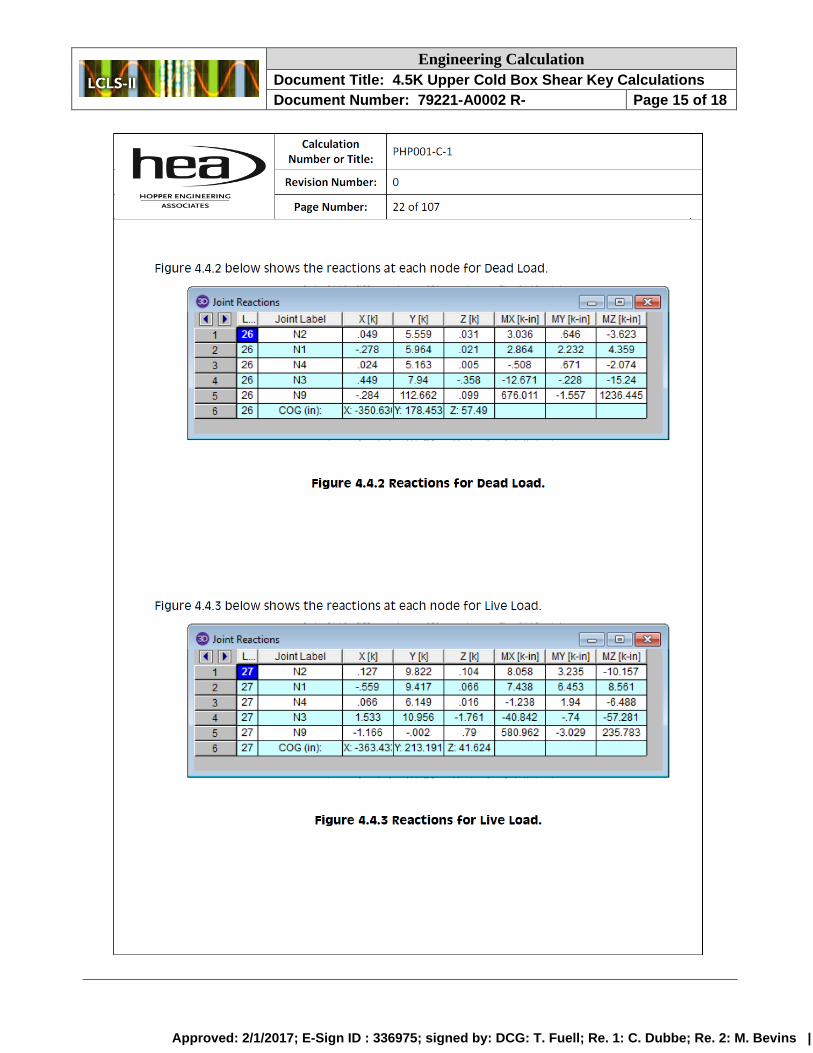
The structural height of the UCB, hn = 388” in 12.8-7 above, is in accordance with the FEA analysis
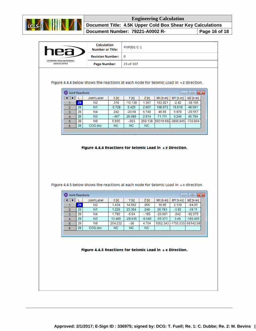
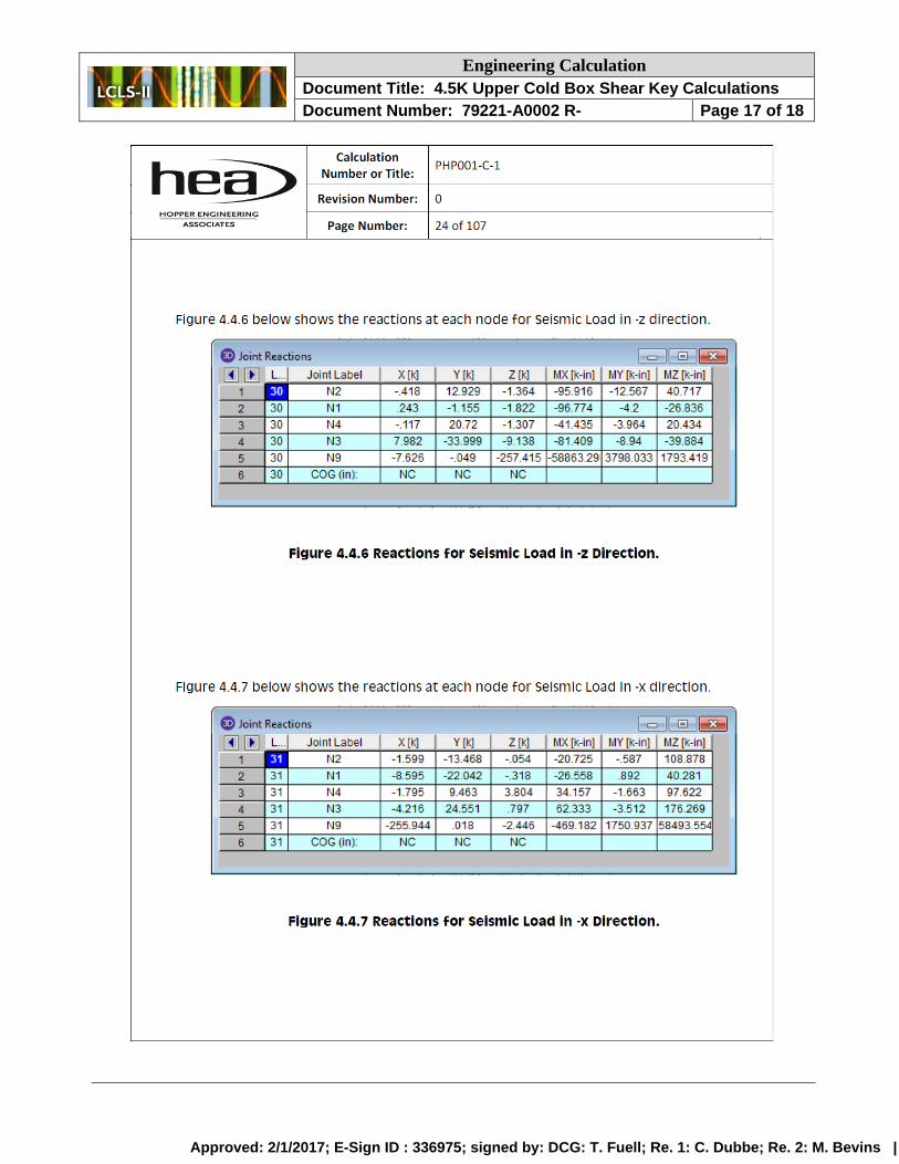
of the UCB itself [5]. This report also includes the reaction shear forces at the base of the UCB for
the dead, live and seismic loads (see Appendix A). To accurately reflect the influence of the
attached platform / stairs and cryoduct, the UCB shear design shear force is based on these reaction
forces. As the seismic reaction forces are based on a seismic base shear of V = 1.968 W, the
seismic reaction forces are factored by 2/3. To ensure the shear keys are designed for the most
critical load effect, the seismic shear reaction force is calculated from the maximum X and Z
components from a Z seismic acceleration and 30% of the maximum X and Z components from a X
seismic acceleration, in accordance with ASCE 7-10 12.5.3.1. In this way, the UCB shear forces
are
Dead = 300 lbs
Live = 1,200 lbs
Seismic = 193,000 lbs
The seismic shear force is ~6% higher than calculated from the reaction shear forces in Appendix A
as this force was determined from a preliminary draft version of the report.
The design load combinations are specified in ASCE 7-10 2.3.2. Considering the shear loads
applied to the shear keys, the two potential determining load combinations are, in accordance with
ASCE 7-10 12.4.2.3,
Approved: 2/1/2017; E-Sign ID : 336975; signed by: DCG: T. Fuell; Re. 1: C. Dubbe; Re. 2: M. Bevins |

Engineering Calculation
Document Title: 4.5K Upper Cold Box Shear Key Calculations
Document Number: 79221-A0002 R- Page 8 of 18
5. (1.2 + 0.2 SDS) D + ρQE + L + 0.2S
7. (0.9 - 0.2 SDS) D + ρQE
The snow load, S, is zero for the UCB and ρ = 1 per ASCE 7-10 15.6.
The shear key embedment is in accordance with ACI 318-2011 [6] and, because this standard does
not address shear keys, ACI 349-13 [7]. The shear keys are designed using option (a) in D.3.3.5.3
of ACI 318-11. Namely, the shear keys are designed for the maximum shear that can be
transmitted to them based on the development of a ductile yield mechanism. In this case, yielding
of the anchor bolts limits the shear force that can be applied to shear keys. In accordance with the
anchor bolt design calculations [8], the anchor bolts are designed to yield with application of a
4,246,000 ft-lb moment (due to a 193,000 lb shear force at a center of gravity 22 feet above the
vessel base) and a 60,400 lb effective vessel weight. This application corresponds to ASCE 7-10
load combination 7. As the effective vessel weight increases, a greater moment is required to yield
the anchor bolts. Thus, load combination 5 is the design combination for the shear keys.
The shear force that will cause the anchor bolts to yield with a dead load of 179,600, where D =
112,662 lbs per the Upper Cold Box General Arrangement [9], is calculated to be
4,246,000 −75
12(60,400) = 𝑄𝐸 (22) −
75
12(179,600)
𝑄𝐸 = 226,900 𝑙𝑏𝑠
where 75” is the radius of the anchor bolt circle. Thus, the load combination shear force is
5. (1.2 + 0.2 SDS) D + ρQE + L + 0.2S
5. (1.2 + 0.2 (1.968)) 300 + 226,900 + 1,200 + 0.2 (0)
5. V = 228,600 lbs
Considering material overstrength in the ductile yield mechanism (in accordance with ACI 318-11
D.3.3.5.3(a)), the shear key design force is taken as 1.2 times this load combination shear force (the
overstrength factor used in ACI 318-11 D.3.3.4.3(a)). Consequently, the UCB design shear force is
V = 274,300 lbs
To ensure the shear keys are suitable for the UCB design shear force,
- The resistance from friction to the applied seismic force is conservatively assumed to be
negligible (as required by ACI 349-13 D.4.6.1).
- The resistance to the applied seismic force due to confinement provided by the anchor
bolts in tension (see ACI 349-13 D.4.6.1 and D.11) is conservatively assumed to be
negligible
- The resistance to the applied seismic force at the moment the ductile yield mechanism
develops in the anchor bolts is conservatively assumed to be resisted by 4 of the 12 shear
keys
Approved: 2/1/2017; E-Sign ID : 336975; signed by: DCG: T. Fuell; Re. 1: C. Dubbe; Re. 2: M. Bevins |

Engineering Calculation
Document Title: 4.5K Upper Cold Box Shear Key Calculations
Document Number: 79221-A0002 R- Page 9 of 18
Additional parameters used in analyzing the shear keys include
- The shear lug separation (38.8”) is sufficient for the shear lugs to be analyzed as single
lugs
- As the shear stiffness of each lug is the same, the magnitude of shear applied to each lug
is equivalent (ACI 349-13 D.11).
- The distance to the nearest edge (in excess of five feet) is such that shear concrete
breakout is not a concern
- The grout compressive strength exceeds the concrete compressive strength
- The ASCE 7-10 load combinations are analogous to the ACI 349-13 9.2 load
combinations
- A shear key is suitable for the UCB design shear force if the bearing strength of the
concrete exceeds the applied bearing load, the reaction shear load does not yield the
shear key in shear, the resulting moment does not yield the shear key in bending and the
attachment weld is sufficient for the shear / moment applied at the shear key-baseplate
connection
4.0 Concrete Bearing
First, it is determined if the bearing strength of the concrete exceeds the bearing load applied by the
shear keys.
Per ACI 349-13 RD11.1, the shear key “bearing area should be limited to the contact area below the
plane defined by the concrete surface.” Per ACI 349-13 D.4.6.2, the concrete design bearing
strength is 1.3 times the concrete compressive strength modified by the strength reduction factor
(1.3 φ fc’).
The concrete bearing strength is compared to the bearing load, where the Concrete Compressive
Strength is 4,000 PSI per Revision A0 of S-001 (ID-905-300-00) in HDR IFC Cryoplant Building
drawings [9].
• 𝜎𝐷𝐶 = 𝐷𝑒𝑠𝑖𝑔𝑛 𝐶𝑜𝑛𝑐𝑟𝑒𝑡𝑒 𝐵𝑒𝑎𝑟𝑖𝑛𝑔 𝑆𝑡𝑟𝑒𝑛𝑔𝑡ℎ
• 𝜎𝑆𝐶 = 𝑆ℎ𝑒𝑎𝑟 𝐾𝑒𝑦 𝐶𝑜𝑛𝑐𝑟𝑒𝑡𝑒 𝐵𝑒𝑎𝑟𝑖𝑛𝑔 𝑆𝑡𝑟𝑒𝑠𝑠
• 𝐴𝑆 = 𝑆ℎ𝑒𝑎𝑟 𝐾𝑒𝑦 𝐵𝑒𝑎𝑟𝑖𝑛𝑔 𝐴𝑟𝑒𝑎
• 𝐷𝑆𝑂 = 𝑆ℎ𝑒𝑎𝑟 𝐾𝑒𝑦 𝑂𝑢𝑡𝑒𝑟 𝐷𝑖𝑎𝑚𝑒𝑡𝑒𝑟 = 6.625"
• 𝐻 = 𝑆ℎ𝑒𝑎𝑟 𝐾𝑒𝑦 𝐺𝑟𝑜𝑢𝑡 𝐻𝑜𝑙𝑒 𝐷𝑖𝑎𝑚𝑒𝑡𝑒𝑟 = 1.5"
• 𝐿𝑆 = 𝑆ℎ𝑒𝑎𝑟 𝐾𝑒𝑦 𝐿𝑒𝑛𝑔𝑡ℎ = 8"
• 𝐺 = 𝐺𝑟𝑜𝑢𝑡 𝐻𝑒𝑖𝑔ℎ𝑡 = 2"
• 𝐴𝑆 = 𝐷𝑆𝑂(𝐿𝑆 − 𝐺) − 𝜋(
𝐻
2)
2
2= 6.625 (8 − 2) −
𝜋(1.5
2)
2
2
Approved: 2/1/2017; E-Sign ID : 336975; signed by: DCG: T. Fuell; Re. 1: C. Dubbe; Re. 2: M. Bevins |

Engineering Calculation
Document Title: 4.5K Upper Cold Box Shear Key Calculations
Document Number: 79221-A0002 R- Page 10 of 18
• 𝐴𝑆 = 38.86 𝑖𝑛2
• φ = 𝑆𝑡𝑟𝑒𝑔𝑛𝑡ℎ 𝑅𝑒𝑑𝑢𝑐𝑡𝑖𝑜𝑛 𝐹𝑎𝑐𝑡𝑜𝑟 = 0.65 (D.4.4, RD.4.6.2)
• 𝑓𝑐′ = 𝐶𝑜𝑛𝑐𝑟𝑒𝑡𝑒 𝐶𝑜𝑚𝑝𝑟𝑒𝑠𝑠𝑖𝑣𝑒 𝑆𝑡𝑟𝑒𝑛𝑔𝑡ℎ = 4,000 𝑝𝑠𝑖
• 𝜎𝐷𝐶 > 𝜎𝑆𝐶
• 1.3φ𝑓𝑐′ >
(𝑉/4)
𝐴𝑆
• 1.3 (0.65)4,000 >(274,300/4)
38.86
• 𝟑, 𝟑𝟖𝟎 𝒑𝒔𝒊 > 𝟏, 𝟕𝟔𝟓 𝒑𝒔𝒊
Thus, the design concrete bearing strength exceeds the bearing load applied by the shear keys.
5.0 Shear Key
Second, it is determined if the reaction load yields the shear keys in either shear or bending.
Combined shear and bending need not be considered as maximum shear and bending occur 90°
apart. This evaluation is in accordance with ACI 349-13 D.10 and the requirement that the design
strength of shear lugs shall be based on the specified yield strength instead of the specified tensile
strength.
The maximum shear stress in the pipe is compared to the design shear stress. The shear stress
varies around the circumference of the pipe in accordance with the sine of the angle from the
direction of force, (V sinθ)/(π Rm T) [10]. As such, the maximum stress occurs 90° from the
direction of force. As the hole in the shear key is not oriented at the point of maximum stress it is
not included in the comparison.
• 𝜎𝐷𝑆 = 𝐷𝑒𝑠𝑖𝑔𝑛 𝑆ℎ𝑒𝑎𝑟 𝐾𝑒𝑦 𝑆ℎ𝑒𝑎𝑟 𝑆𝑡𝑟𝑒𝑠𝑠
• 𝜎𝑆𝑆 = 𝑀𝑎𝑥𝑖𝑚𝑢𝑚 𝑆ℎ𝑒𝑎𝑟 𝐾𝑒𝑦 𝑆ℎ𝑒𝑎𝑟 𝑆𝑡𝑟𝑒𝑠𝑠
• 𝑅𝑚 = 𝑆ℎ𝑒𝑎𝑟 𝐾𝑒𝑦 𝑀𝑒𝑑𝑖𝑎𝑛 𝑅𝑎𝑑𝑖𝑢𝑠 = (𝐷𝑆𝑂 − 𝑇)/2
• 𝐷𝑆𝑂 = 𝑆ℎ𝑒𝑎𝑟 𝐾𝑒𝑦 𝑂𝑢𝑡𝑒𝑟 𝐷𝑖𝑎𝑚𝑒𝑡𝑒𝑟 = 6.625"
• 𝑇 = 𝑆ℎ𝑒𝑎𝑟 𝐾𝑒𝑦 𝑊𝑎𝑙𝑙 𝑇ℎ𝑖𝑐𝑘𝑛𝑒𝑠𝑠 = 0.432”
• 𝐹𝑌 = 𝑆ℎ𝑒𝑎𝑟 𝐾𝑒𝑦 𝑀𝑖𝑛 𝑌𝑖𝑒𝑙𝑑 𝑆𝑡𝑟𝑒𝑛𝑔𝑡ℎ = 35,000 𝑝𝑠𝑖
• φ = 𝑆𝑡𝑟𝑒𝑔𝑛𝑡ℎ 𝑅𝑒𝑑𝑢𝑐𝑡𝑖𝑜𝑛 𝐹𝑎𝑐𝑡𝑜𝑟 = 0.55 (D.4.4, RD.10)
• 𝜎𝐷𝑆 > 𝜎𝑆𝑆
Approved: 2/1/2017; E-Sign ID : 336975; signed by: DCG: T. Fuell; Re. 1: C. Dubbe; Re. 2: M. Bevins |

Engineering Calculation
Document Title: 4.5K Upper Cold Box Shear Key Calculations
Document Number: 79221-A0002 R- Page 11 of 18
• φ𝐹𝑌 >(𝑉/4) sin(90°)
𝜋𝑅𝑚𝑇
• (0.55)35,000 >(274,300/4)(1)
𝜋((6.625−0.432)/2)0.432
• 𝟏𝟗, 𝟐𝟓𝟎 𝒑𝒔𝒊 > 𝟏𝟔, 𝟑𝟏𝟖 𝒑𝒔𝒊
The maximum bending stress in the pipe is compared to the design bending stress. The maximum
stress occurs in line with the direction of force at the connection to the UCB baseplate. As the hole
in the shear key is away from the point of maximum stress (in orientation and elevation), it is not
included in the comparison.
• 𝜎𝐷𝐵 = 𝐷𝑒𝑠𝑖𝑔𝑛 𝑆ℎ𝑒𝑎𝑟 𝐾𝑒𝑦 𝐵𝑒𝑛𝑑𝑖𝑛𝑔 𝑆𝑡𝑟𝑒𝑠𝑠
• 𝜎𝑆𝐵 = 𝑀𝑎𝑥𝑖𝑚𝑢𝑚 𝑆ℎ𝑒𝑎𝑟 𝐾𝑒𝑦 𝐵𝑒𝑛𝑑𝑖𝑛𝑔 𝑆𝑡𝑟𝑒𝑠𝑠
• 𝑆𝑆 = 𝑆ℎ𝑒𝑎𝑟 𝐾𝑒𝑦 𝑆𝑒𝑐𝑡𝑖𝑜𝑛 𝑀𝑜𝑑𝑢𝑙𝑢𝑠
• 𝐷𝑆𝑂 = 𝑆ℎ𝑒𝑎𝑟 𝐾𝑒𝑦 𝑂𝑢𝑡𝑒𝑟 𝐷𝑖𝑎𝑚𝑒𝑡𝑒𝑟 = 6.625"
• 𝑇 = 𝑆ℎ𝑒𝑎𝑟 𝐾𝑒𝑦 𝑊𝑎𝑙𝑙 𝑇ℎ𝑖𝑐𝑘𝑛𝑒𝑠𝑠 = 0.432”
• 𝑆𝑆 =𝜋
32
(𝐷𝑆𝑂4−(𝐷𝑆𝑂−2𝑇)4)
𝐷𝑆𝑂= 12.22 𝑖𝑛3
• 𝐿𝑆 = 𝑆ℎ𝑒𝑎𝑟 𝐾𝑒𝑦 𝐿𝑒𝑛𝑔𝑡ℎ = 8"
• 𝐺 = 𝐺𝑟𝑜𝑢𝑡 𝐻𝑒𝑖𝑔ℎ𝑡 = 2"
• 𝐹𝑌 = 𝑆ℎ𝑒𝑎𝑟 𝐾𝑒𝑦 𝑀𝑖𝑛 𝑌𝑖𝑒𝑙𝑑 𝑆𝑡𝑟𝑒𝑛𝑔𝑡ℎ = 35,000 𝑝𝑠𝑖
• φ = 𝑆𝑡𝑟𝑒𝑔𝑛𝑡ℎ 𝑅𝑒𝑑𝑢𝑐𝑡𝑖𝑜𝑛 𝐹𝑎𝑐𝑡𝑜𝑟 = 0.90 (D.4.4, RD.10)
• 𝜎𝐷𝐵 > 𝜎𝑆𝐵
• φ𝐹𝑌 >(𝑉/4)(𝐺+
𝐿𝑆−𝐺
2)
𝑆𝑆
• (0.9)35,000 >(274,300/4)(2+(8−2)/2)
12.22
• 𝟑𝟏, 𝟓𝟎𝟎 𝒑𝒔𝒊 > 𝟐𝟖, 𝟎𝟓𝟗 𝒑𝒔𝒊
Thus, the design shear key strength exceeds the reaction load applied on the shear keys.
6.0 Attachment Weld
Approved: 2/1/2017; E-Sign ID : 336975; signed by: DCG: T. Fuell; Re. 1: C. Dubbe; Re. 2: M. Bevins |
Engineering Calculation
Document Title: 4.5K Upper Cold Box Shear Key Calculations
Document Number: 79221-A0002 R- Page 12 of 18
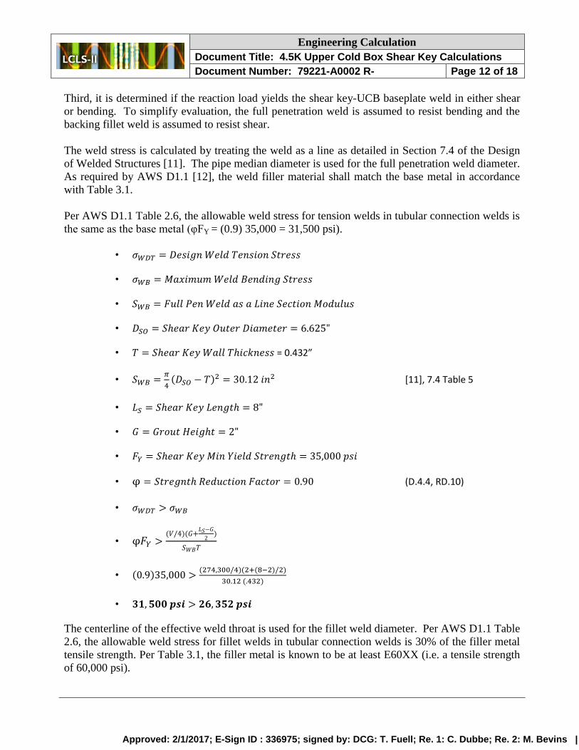
Third, it is determined if the reaction load yields the shear key-UCB baseplate weld in either shear
or bending. To simplify evaluation, the full penetration weld is assumed to resist bending and the
backing fillet weld is assumed to resist shear.
The weld stress is calculated by treating the weld as a line as detailed in Section 7.4 of the Design
of Welded Structures [11]. The pipe median diameter is used for the full penetration weld diameter.
As required by AWS D1.1 [12], the weld filler material shall match the base metal in accordance
with Table 3.1.
Per AWS D1.1 Table 2.6, the allowable weld stress for tension welds in tubular connection welds is
the same as the base metal (φFY = (0.9) 35,000 = 31,500 psi).
• 𝜎𝑊𝐷𝑇 = 𝐷𝑒𝑠𝑖𝑔𝑛 𝑊𝑒𝑙𝑑 𝑇𝑒𝑛𝑠𝑖𝑜𝑛 𝑆𝑡𝑟𝑒𝑠𝑠
• 𝜎𝑊𝐵 = 𝑀𝑎𝑥𝑖𝑚𝑢𝑚 𝑊𝑒𝑙𝑑 𝐵𝑒𝑛𝑑𝑖𝑛𝑔 𝑆𝑡𝑟𝑒𝑠𝑠
• 𝑆𝑊𝐵 = 𝐹𝑢𝑙𝑙 𝑃𝑒𝑛 𝑊𝑒𝑙𝑑 𝑎𝑠 𝑎 𝐿𝑖𝑛𝑒 𝑆𝑒𝑐𝑡𝑖𝑜𝑛 𝑀𝑜𝑑𝑢𝑙𝑢𝑠
• 𝐷𝑆𝑂 = 𝑆ℎ𝑒𝑎𝑟 𝐾𝑒𝑦 𝑂𝑢𝑡𝑒𝑟 𝐷𝑖𝑎𝑚𝑒𝑡𝑒𝑟 = 6.625"
• 𝑇 = 𝑆ℎ𝑒𝑎𝑟 𝐾𝑒𝑦 𝑊𝑎𝑙𝑙 𝑇ℎ𝑖𝑐𝑘𝑛𝑒𝑠𝑠 = 0.432”
• 𝑆𝑊𝐵 =𝜋
4(𝐷𝑆𝑂 − 𝑇)2 = 30.12 𝑖𝑛2 [11], 7.4 Table 5
• 𝐿𝑆 = 𝑆ℎ𝑒𝑎𝑟 𝐾𝑒𝑦 𝐿𝑒𝑛𝑔𝑡ℎ = 8"
• 𝐺 = 𝐺𝑟𝑜𝑢𝑡 𝐻𝑒𝑖𝑔ℎ𝑡 = 2"
• 𝐹𝑌 = 𝑆ℎ𝑒𝑎𝑟 𝐾𝑒𝑦 𝑀𝑖𝑛 𝑌𝑖𝑒𝑙𝑑 𝑆𝑡𝑟𝑒𝑛𝑔𝑡ℎ = 35,000 𝑝𝑠𝑖
• φ = 𝑆𝑡𝑟𝑒𝑔𝑛𝑡ℎ 𝑅𝑒𝑑𝑢𝑐𝑡𝑖𝑜𝑛 𝐹𝑎𝑐𝑡𝑜𝑟 = 0.90 (D.4.4, RD.10)
• 𝜎𝑊𝐷𝑇 > 𝜎𝑊𝐵
• φ𝐹𝑌 >(𝑉/4)(𝐺+
𝐿𝑆−𝐺
2)
𝑆𝑊𝐵𝑇
• (0.9)35,000 >(274,300/4)(2+(8−2)/2)
30.12 (.432)
• 𝟑𝟏, 𝟓𝟎𝟎 𝒑𝒔𝒊 > 𝟐𝟔, 𝟑𝟓𝟐 𝒑𝒔𝒊
The centerline of the effective weld throat is used for the fillet weld diameter. Per AWS D1.1 Table
2.6, the allowable weld stress for fillet welds in tubular connection welds is 30% of the filler metal
tensile strength. Per Table 3.1, the filler metal is known to be at least E60XX (i.e. a tensile strength
of 60,000 psi).
Approved: 2/1/2017; E-Sign ID : 336975; signed by: DCG: T. Fuell; Re. 1: C. Dubbe; Re. 2: M. Bevins |

Engineering Calculation
Document Title: 4.5K Upper Cold Box Shear Key Calculations
Document Number: 79221-A0002 R- Page 13 of 18
• 𝜎𝑊𝐷𝑆 = 𝐷𝑒𝑠𝑖𝑔𝑛 𝑊𝑒𝑙𝑑 𝑆ℎ𝑒𝑎𝑟 𝑆𝑡𝑟𝑒𝑠𝑠 = 18,000 𝑝𝑠𝑖
• 𝜎𝑊𝑆 = 𝑀𝑎𝑥𝑖𝑚𝑢𝑚 𝑊𝑒𝑙𝑑 𝑆ℎ𝑒𝑎𝑟 𝑆𝑡𝑟𝑒𝑠𝑠
• 𝐿𝑊𝐹 = 𝐹𝑖𝑙𝑙𝑒𝑡 𝑊𝑒𝑙𝑑 𝐿𝑒𝑛𝑔𝑡ℎ
• 𝑇𝑊𝐹 = 𝐹𝑖𝑙𝑙𝑒𝑡 𝑊𝑒𝑙𝑑 𝐸𝑓𝑓𝑒𝑐𝑡𝑖𝑣𝑒 𝑇ℎ𝑟𝑜𝑎𝑡 = .265"
• 𝐷𝑊𝐹 = 𝐹𝑖𝑙𝑙𝑒𝑡 𝑇ℎ𝑟𝑜𝑎𝑡 𝐶𝑒𝑛𝑡𝑒𝑟𝑙𝑖𝑛𝑒 𝐷𝑖𝑎𝑚𝑒𝑡𝑒𝑟 = 6.8125"
• 𝐿𝑊𝐹 = 𝜋(𝐷𝑊𝐹) = 𝜋(6.8125) = 21.4 𝑖𝑛
• 𝜎𝑊𝐷𝑆 > 𝜎𝑊𝑆
• 18,000 >(𝑉/4)
𝑆𝑊𝐹𝑇𝑊𝐹
• 18,000 >(274,300/4)
21.4 (.265)
• 𝟏𝟖, 𝟎𝟎𝟎 𝒑𝒔𝒊 > 𝟏𝟐, 𝟎𝟗𝟑 𝒑𝒔𝒊
7.0 Summary / Conclusions
The bearing strength of the concrete exceeds the applied bearing load. The reaction shear load does
not yield the shear key in shear and the resulting moment does not yield the shear key in bending.
The attachment weld is sufficient for the shear / moment applied at the shear key-baseplate
connection. Thus, the UCB shear key design is acceptable.
8.0 References
[1] California Building Code, 2013
[2] Minimum Design Loads for Buildings and Other Structures. ASCE/SEI 7-10, 2010
[3] Final Report Geotechnical Investigation LCLS II Cryogenic Building and Infrastructure
SLAC National Accelerator Laboratory, Rutherford+Chekene #2014-106G
[4] Cryogenic Plant Seismic Design Criteria, LCLSII-4.8-EN-0227-R2
[5] Hopper Report – Component Seismic Design (PHP001-C1), Air Liquide C1303-NT-300 Rev0
[6] Building Code Requirements for Structural Concrete, ACI 318-11
[7] Code Requirements for Nuclear Safety-Related Concrete Structures, ACI 349-13
[8] Upper Cold Box Base Conn Calcs, Rutherford+Chekene CB1-CB14 12/6/2016
[9] LCLS-II Cryogenic Building and Infrastructure IFC Submittal, ID-905-000-00
[10] Mechanics of Materials, Beer, Johnston Jr and DeWolf – 3rd
Ed, p. 400, 781
[11] Design of Welded Structures, Blodgett, 1966
[12] Structural Welding Code—Steel, AWS D1.1/D1.1M 2015
Approved: 2/1/2017; E-Sign ID : 336975; signed by: DCG: T. Fuell; Re. 1: C. Dubbe; Re. 2: M. Bevins |

Engineering Calculation
Document Title: 4.5K Upper Cold Box Shear Key Calculations
Document Number: 79221-A0002 R- Page 14 of 18
Appendix A – UCB Reaction Shear Forces
Approved: 2/1/2017; E-Sign ID : 336975; signed by: DCG: T. Fuell; Re. 1: C. Dubbe; Re. 2: M. Bevins |
Engineering Calculation
Document Title: 4.5K Upper Cold Box Shear Key Calculations
Document Number: 79221-A0002 R- Page 15 of 18
Approved: 2/1/2017; E-Sign ID : 336975; signed by: DCG: T. Fuell; Re. 1: C. Dubbe; Re. 2: M. Bevins |
Engineering Calculation
Document Title: 4.5K Upper Cold Box Shear Key Calculations
Document Number: 79221-A0002 R- Page 16 of 18
Approved: 2/1/2017; E-Sign ID : 336975; signed by: DCG: T. Fuell; Re. 1: C. Dubbe; Re. 2: M. Bevins |
Engineering Calculation
Document Title: 4.5K Upper Cold Box Shear Key Calculations
Document Number: 79221-A0002 R- Page 17 of 18
Approved: 2/1/2017; E-Sign ID : 336975; signed by: DCG: T. Fuell; Re. 1: C. Dubbe; Re. 2: M. Bevins |

Engineering Calculation
Document Title: 4.5K Upper Cold Box Shear Key Calculations
Document Number: 79221-A0002 R- Page 18 of 18
Approved: 2/1/2017; E-Sign ID : 336975; signed by: DCG: T. Fuell; Re. 1: C. Dubbe; Re. 2: M. Bevins |