44 1 passive components and circuits - ccp lecture 2 introduction
TRANSCRIPT

/441
Passive components and circuits - CCP
Lecture 2
Introduction

/442
Index
Electrical quantities Ideal and real sources Electrical signals Electrical circuits topology Transmittances Ohm’s law

/443
Electrical quantities Electrical voltage is equal with the differences between
electrical potential of two points. Is measured in Volts [V]. It is denoted with u or v. The voltage appears between component terminals.
The electrical current represents an electrical charge flow. It is measured in Amps [A]. A current equal with 1A represents the flow of a 1 Coulomb charge through a conductor on a 1s period. The current is denoted with i.
The electrical current appears only in conductors.
The current appears in a circuit only if we have a conductive loop.

/444
Electrical quantities The multiplying of voltage and current represents
the electrical power. It is measured in Watts [W]. The power distributed or absorbed by a circuit in
time unit is called electrical energy. It is measured in Joules [J]. In measuring of energy distributed by power grid we use [kWh].
For additional information:
http://scienceworld.wolfram.com/
http://www.megaconverter.com/Mega2/

/445
Conventional directions for voltages and currents The conventional direction for electrical
voltage between two points is from higher to lower potential.
The conventional (positive) direction of the electrical current is the direction of positive-charged particles flow, producing the same effect as a flow of negatively charged particles (electrons), representing the actual current flow.

/446
Conventional directions for voltages and currents
Prior to the analysis of an electric circuit, the conventional directions of the currents in the circuit are not known.
So, before writing the equations (Kirchhoff’s laws) for each loop, a positive arbitrary direction is selected for each branch of the circuit.
After performing the analysis of the circuit, if the value of the current is positive, the arbitrary and conventional directions of the current flow are identical. If the value of the current is negative, the conventional direction is opposite to the arbitrary selected direction.
elem ent de circuitA B
vAB
elem ent de circuitA B
i
Circuit element
Circuit element
/447
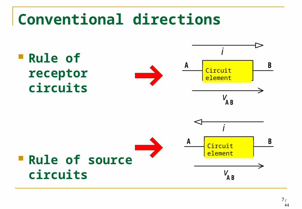
Conventional directions
Rule of receptor circuits
Rule of source circuits
elem ent de circuitA B
vAB
i
elem ent de circuitA B
vAB
i
Circuit element
Circuit element

/448
Generators and loads
If the current and voltage arrows point into the opposite direction (corresponding to the real situation-the calculated power is positive) the power is generated (delivered). For example, it is obvious that in the case of resistors the power is only consumed.
)()()( titvtp
T
med dttitvT
P )()(1
Instantaneous power
Average power

/449
Ideal sources Applying some electrical quantities in the circuit can
be symbolized using some circuit elements called voltage or current sources. An ideal voltage source will always maintain the
voltage across its terminals at the voltage indicated, regardless of the value of the current at its terminals.
An ideal current source will always pass the indicated current out of the positive terminal and this current will return to the source at the negative terminal, regardless of the value of the voltage across its terminals.
/4410
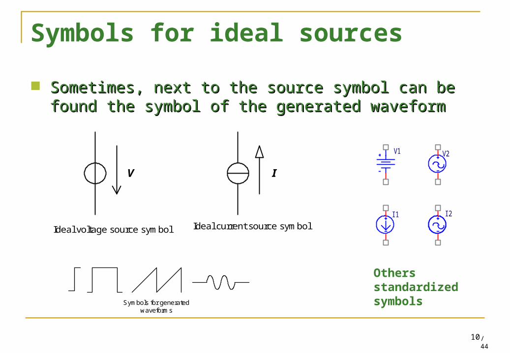
Symbols for ideal sources
Sometimes, next to the source symbol can be found the Sometimes, next to the source symbol can be found the symbol of the generated waveformsymbol of the generated waveform
Symbols for generated waveforms
I2
V1
I1
V2
V I
Ideal voltage source symbol Ideal current source symbol
Others standardized symbols

/4411
Important remarks! It is forbidden to connect in parallel ideal voltage sources. It is forbidden to connect in series ideal current sources. It is forbidden to connect in short-circuit an ideal voltage
source. The term short-circuit means that the impedance between the terminals is zero. If we connect in short-circuit an ideal voltage source, the current flowing would be infinite.
It is forbidden to let the ideal current source in open circuit. The term open circuit means that the impedance between the terminals is infinite. If the terminals of an ideal current source are in open circuit, the voltage across its terminals would be infinite.

/4412
Real sources model A real (practical) voltage source has an internal resistance,
Ro, in series, desirable to be very small (aiming to zero). A real (practical) current source has an internal resistance,
Ro, in parallel, desirable to be very high (aiming to infinite). AB port is output port and Ro is internal resistance.
V
Model of real voltage source
I
Model of real current source
AA
BB
RO
RO

/4413
Electrical voltage generators
Battery
Electrical plant
Laboratory sources
Nerves
1.5 V
9 V
13,500 V13,500 V
Few volts
Photovoltaic cells
Some milivolts

/4414
Laboratory voltage source
Important: The voltage is measured between two points
Voltage up to 10 V
Red (+) andBlack (-) Are equivalent with a batteryterminals
Voltage regulation
Earth-protection

/4415
Voltage measurementThe voltages are measured with a multimeter
I COM V
volts
The red terminal is connected to V
The black terminal is connected to COM (common)
Read the voltage
The voltage range will be set
+2.62

/4416
Exercise
We set the voltage source at 3.2 V. What will be displayed on the multimeter?
I COM V
–3.2 V
Answer: –3.2 V

/4417
Electrical signal
A variable quantity, that carries information is called signal.
If the variable physical quantity does not carry information it is called noise.
In electric circuits, two types of electrical signals are presented: voltage current

/4418
Symbols for electrical signals Any signal is denoted by letter symbol and one or
more indices. Letters and indices have a double significance:
By name of the letter By letter character (capital or low case letter)
vo .... ? Vo .... ?
vO .... ? VO ... ?

/4419
Significance of letter name The signals are symbolized with the corresponding
letters: i or I for the intensity of the current and v or V for voltages
The letters are accompanied by indices (subscript letters) suggesting the measuring conditions or position in the circuit for those measurements (average value, maximum etc).
Example: I or i indices means input, and o or O means output.
/4420
Significance of letter type
Capital letter symbols, such as I, U, P indicate a constant value in time (direct current regime) or a characteristic value of the variable signal (maximum, medium, effective).
Low case letters used as symbols u, i, p denote an instantaneous value of an electrical magnitude, variable in time.

/4421
Significance of indices letter type Capital letter at indices means a total value. Low case letter at indices means a value of a
variable component of signals.
In case of editing text, italic, bold, roman have standardized signification. For more information visit:
http://physics.nist.gov/cuu/Units/

/4422
Examples
vO – Total instantaneous value: combination of low case
letter and capital indices is generic for any type of signal
VO – Total constant value (also called static value or
average value);
vo – instantaneous value of variable components of output
voltage; is equal with difference between total instantaneous value and static value.
Vo – effective value (root mean square value ) of variable
components of output voltage

/4423
Medium, instantaneous and rms Medium, instantaneous and rms valuesvalues
Ov
dttvT
VT )(
1OO
OOo Vvv
T
dttvT
V )(1 2
oo
Its medium value in a period T
An output voltage
Instantaneous value of variable component
The rms (root mean square) value (effective value) of variable component
/4424
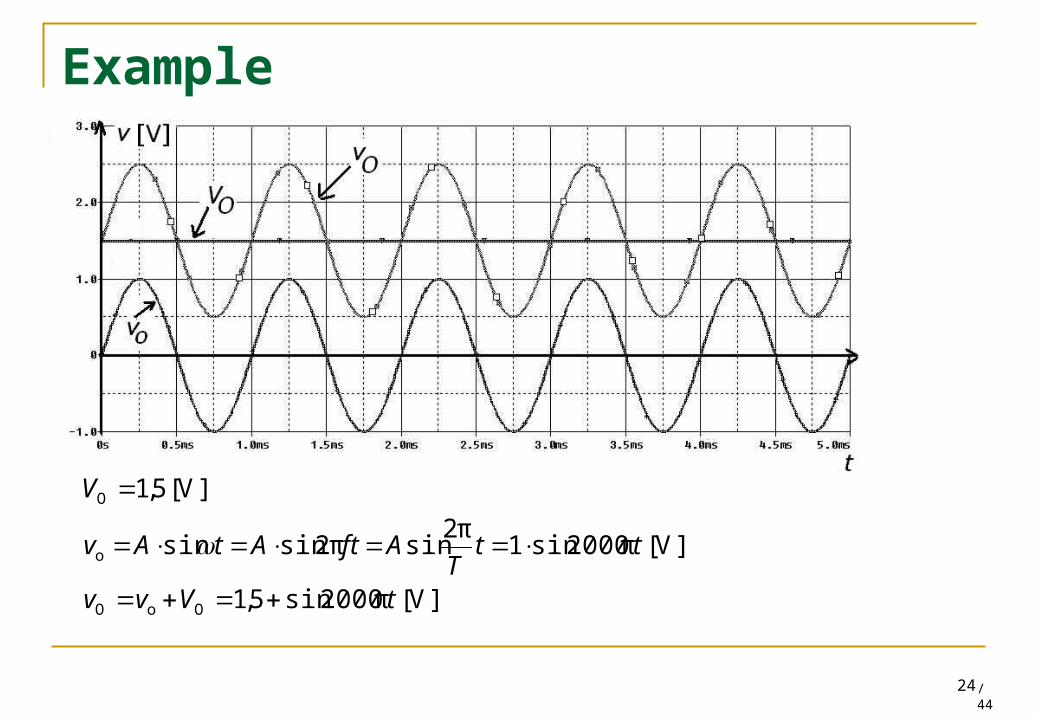
Example
]V[π2000sin5,1
]V[π2000sin1π2
sinπ2sinsin
]V[5,1
OoO
o
O
tVvv
ttT
AftAtAv
V

/4425
Typical signals for electronics systems
ZpTpkTpTtA
kTpTpTtBtv
])1(;[;
];[;)(
t
v
0
A
B
TkT
AkkBVmed )1(
Rectangular signal

/4426
Other signal shapes
Trapezoidal signal
Triangular signal
Saw-tooth signal
t
v
0
A
B
t0
v
A
B
t0
v
A
B

/4427
Topology of electrical circuits The interconnection of a set of electrical/electronics components is called
network or an electrical/electronics diagram. By replacing of components with circuit elements (that describe the electrical
properties of components) we obtain the equivalent electrical/electronic circuit. Each element type is characterized by its function between voltage and current.
Battery
Lamp
SwitchR R
L
B AT L
LvB AT
Electrical diagram Equivalent electrical circuit

/4428
Topology of electrical circuits In practice, the electrical components are interconnected with
wires, conductors, tracks on PCB etc.
The circuit elements from equivalent circuits are interconnected with nodes. Nodes can be simple (when only 2 elements are interconnected) or multiple (when more than 2 elements are interconnected).
The route of current between 2 nodes is called circuit branch.
If each component has a single circuit element as model, then the electrical diagram and the equivalent circuit are identical.

/4429
Components interconnected by wires
Correspondence between electrical diagram-equivalent circuit
branch
nodes
Circuit elements
Multiple node
Multiple node
Simple node

/4430
What is “ground”? The ground of any circuit is a
common reference point, from which all the circuit voltages are measured.
Theoretically, the choosing of the ground point is relative. The position of the ground point doesn’t influence the circuit operation.
The ground point is chosen in the node where the greatest number of branches are convergent.
Practically, it is important where the ground point is positioned.

/4431
Circuit ground
In a circuit, there can be defined a number of ground points: analog ground, digital ground, power ground etc.
The different ground points can be galvanic isolated or not.
Symbols for ground ?

/4432
What is “earth ground”?
Connections of equipment to the earth serve for protection.
Theoretically, the current through the earth conductor is not zero only in a fault case.
The earth connection doesn’t affect the circuit operation.
R1
R2VI
/4433
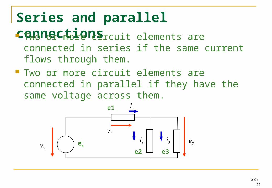
Series and parallel connections Two or more circuit elements are connected in
series if the same current flows through them. Two or more circuit elements are connected in
parallel if they have the same voltage across them.
i1
i2 i3
v1
vs
v2es
e1
e2 e3

/4434
Uniport, diport, multiport Terminals -The access
points of a circuit; Port (gate) – a pair of
terminals (the input current must be equal with the output current);
Uniport – a circuit with a single port;
Diport, triport, multiport - ....
Electronic circuit
T erm in a l
In p u t p o r t O tp u t P o rt
T es t P o rt
S u p p ly P o rt
iI
iI
iO
iO
vI
vO

/4435
Limit operating situations for a gate (port) Open circuit - the impedance between the terminals
is infinite, the current is zero and the voltage reaches the maximum value;
Short-circuit - the impedance between the terminals is zero, the voltage is zero and the current reaches the maximum value.
The two extreme situations are dual.

/4436
Transmittances Transmittance – the ratio between two electrical
signals Non-dimensional – the signals are the same type; Dimensional (immittance) – one signal is voltage and
other signal is current Impedance – voltage/current (are denoted with R and
are measured in ohms – ) Admitance – current/tvoltage (are denoted with G and
are measured in siemens – S) Immittances defined in DC are called:
impedance resistance admittance conductance
/4437
Transfer transmittances Are transmittances defined between signals from different
gates.
If these two gates are one input and the second one output, then: Direct transmittance output signal/input signal Reverse transmittance input signal/output signal
Important: Reverse transmittance does not represent the mathematical inverse function of direct transmittance!

/4438
Ohm’s law
The voltage across a resistor is equal with resistance multiplied with the value of a current through resistor.
RAB iRv R
A B
vAB
iR

/4439
Ohm’s law – equivalent forms
From the mathematical point of view, the Ohm’s law can be written under other two forms.
R
ABABRRAB i
vR
R
viiRv
R
A B
vAB
iR

/4440
Series connection of resistances By a series connection of two resistances it is
obtained an equivalent resistance equal with the sum of those two resistances.
R 1 R 2 R echA AB B
2;1
21
RRRR
RRR
echech
ech
/4441
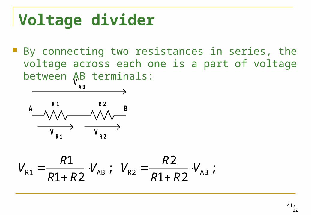
Voltage divider
By connecting two resistances in series, the voltage across each one is a part of voltage between AB terminals:
R 1 R 2A B
VAB
VR1
VR2
;21
2;
21
1ABR2ABR1 V
RR
RVV
RR
RV
/4442
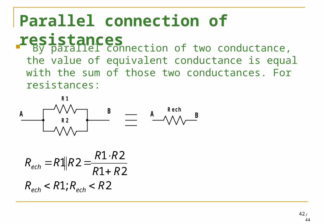
Parallel connection of resistances By parallel connection of two conductance, the value of
equivalent conductance is equal with the sum of those two conductances. For resistances:
2;121
2121
RRRRRR
RRRRR
echech
ech
R echA B
R 1
R 2A B

/4443
Current divider By connecting two resistances in parallel between AB
terminals, the current through each resistance is a part of current that flows between AB terminals:
;21
1;
21
221 ABRABR I
RR
RII
RR
RI
R 1
R 2A B
IAB
IR1
IR2

/4444
Homework
Write the mathematical form of signals presented in slide 26.
For each signal, determine the average value on a period.
For the following circuit, determine the elements connected in series and elements connected in parallel.
e2
e1
e3
e4
e6
e7e5
R1
R2
R3C2C1V1
R1
C2
C1V1
R3
R1 R3C2C1V1
R2
R2C3
e1 e6e4e2 e5e3 e1 e6e4
e2 e5
e3
C2C1
V1
R1 R2
C3 C5V1
R3 R4
R1 R2
C1
C2
C3
C4