41hz audio ai amp 1b
DESCRIPTION
Really hard to find assembly instructions for 41hz audio amp 1b (No longer madeTRANSCRIPT

10/9/13 41Hz Audio - AI-AMP-1B
www.41hz.com/forums/content.php?28-AI-AMP__1-B 1/13
AMP1B Assembly Instructions
Related SubForum: AMP1.
DISCLAIMER! It is assumed that you have thorough knowledge about electronics and building electrical and electronic devices.41Hz.com assumes no responsibility or liability for any injury, loss or damage incurred as a result of any use orreliance upon the information and material contained within or downloaded from its website.
Introduction
The AMP1B is not an AMP1Basic, it is a much improved AMP1, still SMD + inductorcoils. It has thesame specs but also an autoDCoffset circuit and a speakerrelay.

10/9/13 41Hz Audio - AI-AMP-1B
www.41hz.com/forums/content.php?28-AI-AMP__1-B 2/13
Thanks for ordering the AMP!This document will help you build the kit. It has been updated for revision 4.0 boards.
The boards (PCB) for AMP1B are doubleweight, doublesided copper and fully throughmetallized. Thissometimes requires quite a powerful soldering iron to heat.Some components and pads connected to the ground plane require substantial heating.
Needed documents, available under the Downloads tab in your Shop account.
The schematicsBOM (Bill Of Materals)The Tripath chip datasheet for your kit (TA2022)
Considerations before buildingSignal Input CapacitorCin can be calculated once a value for Rin has been determined. Cin and Rin determine the input lowfrequency pole. Typically this pole is set below 10Hz to give a full audio range. Cin is calculated accordingto:
Cin =1/ (2pi * F * Rin)
Rin = Input resistor value in ohms. This is determined by your choice of the input gain, see below.F = Input low frequency pole (typically 10Hz or below).
Normally, a 1 to 3uF capacitor will do, but you can change it: Cin (with Rin) basically forms a highpassfilter, 3dB dropoff at 'F' and more below that. So, if you use a subwoofer, you could set 'F' to 200Hz, forinstance.The supplied caps should suffice.
Selecting the gainThe amplification, or gain, of the amplifier is set in two stages: Input stage gain and power stage gain.Optimally you should match the input gain to your signal source signal level and the power stage gain to yoursupply rail voltage. Just remember that music signals are very dynamic by nature, signal levels areapproximate and impossible to predict accurately.
Input stage gainIn table 1 you can see some typical input signal sources and gains you can set with the supplied components.

10/9/13 41Hz Audio - AI-AMP-1B
www.41hz.com/forums/content.php?28-AI-AMP__1-B 3/13
In table 1 you can see some typical input signal sources and gains you can set with the supplied components.The maximum recommended voltage out of the input stage is +/2V peak to peak (4Vpp = 1.41 Vrms),including some margin. At higher output signals, the input stage may clip.The amplifier input stage in the Tripath chip is of the inverted operational amplifier type. The gain iscalculated as:
Gain = 1 * Rfeedback/Rin
(the 'minus' implies the signal is inverted, not of any consequence here) On the board, R51+R32 are Rin and R43+R44 are Rfeedback.With the kit, there are four 20 kΩ resistors and two 36 kΩ supplied. With these resistor values, you canchoose one of three different input gains/sensitivities as shown in table 1. If you use other input resistor values, they should be of a low noise type and of the 0805 size.
Table 1. Input stage gain setting recommendationsRin, R51+R32 Rfeedback, R43+R44 Input Gain Suitable signal source
20 kΩ 36 kΩ 1.8 Direct connection of portable MP3/CD player with built involume control or via a passive volume pot.
20 kΩ 20 kΩ 1 General use36 kΩ 20 kΩ 0.56 Preamplifier with fairly high output signal
Modulator gainThe “modulator gain” is the power stage voltage gain. You can select this to match your power supply voltage, by selecting the value of the modulator feedbackresistors R31 and R52. Table 2 gives the values for modulator feedback resistors and the rail voltages they are suitable for.
Table 2. Modulator / power stage gainRmfb, R31+R52 Gain [V/V] Suitable rail voltage8.2 kΩ 16 +/24V to +/ 30V10 kΩ 19.3 +/28V to +/ 35V
The total gain is the input stage gain multiplied by the modulator gain. If we assume you have selected theinput stage gain, as you normally should, for a maximum of +/2Vrms output, then the maximum outputvoltage to the speakers will be 2x the modulator gain. For example with 10kΩ feedback resistors, and +/2V from the input stage, you would have +/ 38.6V outmaximum. You can see that the calculated maximum output can be higher than the rail voltage. In reality, theoutput voltage can only be as high as close to the rail voltage.

10/9/13 41Hz Audio - AI-AMP-1B
www.41hz.com/forums/content.php?28-AI-AMP__1-B 4/13
output voltage can only be as high as close to the rail voltage.
Therefore there will be some clipping of the highest peaks at the maximum input signal. This is quite OK and assures you can reach maximum output power at near the maximum input volumesetting.If you decrease the modulator gain, you will not reach maximumpower/clipping even at maximum input signal.
Table 3. Gain setting; summaryInput stage gain ResultInput Gain too low Maximum output is to low. Power stage not fully used.Input Gain correct Output from input stage is +/2V peak to peak at full input volumeInput gain too high Input stage clips before maximum output power is reachedPower stage gainModulator gain toolow Output never reaches maximum power, even with maximum input signal
Modulator gaincorrect Output clips slightly with maximum input signal
Modulator gain toohigh
Output clips excessively at full volume. Input stage is operating at low voltage; increased THD+Nat low power
You might want to change the gain settings differently than what it will be with the supplied components. Inthe data sheet for the Tripath TA2022 chip there are more details on how to calculate the gain, but thespreadsheet in this post will be very convenient to help out: Input and modulator gain
Building/Assembly instructionsIMPORTANTComponents packaged in a shielded, aluminized bag should be considered ESD sensitive and should be handled withESD care. The Tripath chips use MOSFET outputs which by nature are sensitive to ESD (Electro Static Discharge).Use ESD precautions. Preferably work on a conductive, grounded “ESD mat”, and avoid touching the chip leads withyour fingers. Discharge yourself before working with the components.
1. First, solder all surface mount components. They are all placed on the “bottom” side of the board. A component layout is included with yourdelivery and below.TIP/OPTIONyou might want to delay assembly of the smdparts on the edge behind the TA2022 chip (C4143,C4649,R50, make sure to label those well!); this will give you more space to solder the TA2022 in place.
10/9/13 41Hz Audio - AI-AMP-1B
www.41hz.com/forums/content.php?28-AI-AMP__1-B 5/13
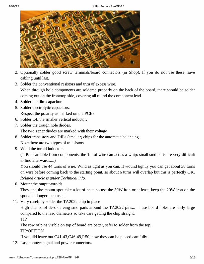
2. Optionally solder good screw terminals/board connectors (in Shop). If you do not use these, savecabling until last.
3. Solder the conventional resistors and trim of excess wire.When through hole components are soldered properly on the back of the board, there should be soldercoming out on the front/top side, covering all round the component lead.
4. Solder the film capacitors5. Solder electrolytic capacitors.
Respect the polarity as marked on the PCBs.6. Solder L4, the smaller vertical inductor.7. Solder the trough hole diodes.
The two zener diodes are marked with their voltage8. Solder transistors and DILs (smaller) chips for the automatic balancing.
Note there are two types of transistors9. Wind the toroid inductors.
(TIP: clear table from components; the 1m of wire can act as a whip: small smd parts are very difficultto find afterwards....) You should use 44 turns of wire. Wind as tight as you can. If wound tightly you can get about 38 turnson wire before coming back to the starting point, so about 6 turns will overlap but this is perfectly OK.Related article is under Technical info.
10. Mount the outputtoroids.They and the mountspot take a lot of heat, so use the 50W iron or at least, keep the 20W iron on thespot a lot longer then usual.
11. Very carefully solder the TA2022 chip in placeHigh chance of desoldereing smd parts around the TA2022 pins... These board holes are fairly largecompared to the lead diameters so take care getting the chip straight. TIPThe row of pins visible on top of board are better, safer to solder from the top.TIP/OPTIONIf you did leave out C4143,C4649,R50, now they can be placed carefully.
12. Last connect signal and power connectors.

10/9/13 41Hz Audio - AI-AMP-1B
www.41hz.com/forums/content.php?28-AI-AMP__1-B 6/13
13. The J1 jumper or wires with a toggling switch are used to mute and turn on the amplifier.If you do not use an external switch, you can permanently put a jumper from the middle hole of J1 tothe Awake side of J1, or use some wire.
Component placement
Components to be placed on TOP of PCB.

10/9/13 41Hz Audio - AI-AMP-1B
www.41hz.com/forums/content.php?28-AI-AMP__1-B 7/13
Components on BOTTOM of PCB. These are very small smd, surface mount devices.

10/9/13 41Hz Audio - AI-AMP-1B
www.41hz.com/forums/content.php?28-AI-AMP__1-B 8/13
Components on BOTTOM of PCB with values.The light green is for resistors, the brown/tan/orange is for different values of capacitors.
Note 1There are 2x 100nF (104) Caps which are 100V (colored in pink), while the rest are only 50V.Note 2For inputgain, this amp is using the default 20kΩ resistors for Rin & Rfeedback R51, 32 & R43, 44respectively, as per Table 1 in the AI (above).For modulator gain, it is also set to use 10kΩ for Rmfb R31 & 52, as per Table 2 in the AI.
Additional componentsThe following will at some stage be needed to complete the amplifier, but is not included in the kit:
HEAT SINK.Screws and heat conductive paste to mount the heat sink. The main source of heat on the board is theTripath chip. In most cases, if you mount the board and chip to an aluminum amplifier casing, it issufficient to cool the chip. However, for high power applications the heat dissipated increases and you must ensure this hasadequate cooling. The Tripath chip does not need to be insulated, as the back of the chip is internallyconnected to ground.HOOKUP WIRE.I recommend soldering connection wires to the board. Optionally you can fit screw/solder terminalswith 2.5mm spacing for the inputs and 5 mm spacing for power and outputs.MUTE/UNMUTE SWITCH or jumper.

10/9/13 41Hz Audio - AI-AMP-1B
www.41hz.com/forums/content.php?28-AI-AMP__1-B 9/13
MUTE/UNMUTE SWITCH or jumper.Preferably wire this to a switch on your panel. Optionally use a 2.54 mm jumper (50 mil) on the board.Muting the amp before power on minimizes the turn on thump and is recommended.POWER SUPPLYSMPS/transformer/battery, power switch and fuse.THE BOARDS Are double weight, double sided copper. Even if the PCB and components are small, quite a powerfulsoldering iron is helpful. Especially components and pads connected to the ground plane requiresignificant heating. A temperature controlled 50W soldering iron is recommended. At the same time, applying excessiveheat may damage the board, causing the copper leads to come off. Preheating the board to around100ºC will make work easier and allows using a lower solder iron temperature which decreases thedamage risk. Some information on how to solder both SMT and holemounted components is available under TechInfo
Your power supply voltage(just an example)
The power supply voltage will influence the voltage sensing. The default components will work from+/20Vdc upto +/35Vdc.This implies a transformer voltage of around 2x15Vac upto 2x25Vac.Above voltages are double, i.e. amp needs a symmetric powersupply as seen in PSexample above. (+/

10/9/13 41Hz Audio - AI-AMP-1B
www.41hz.com/forums/content.php?28-AI-AMP__1-B 10/13
Above voltages are double, i.e. amp needs a symmetric powersupply as seen in PSexample above. (+/is not 'about', but plus and minus)Transformer about 300VA for rated max.power, but depends on your needs.
Hookup and shielding.Switched mode amplifiers are a bit noisy by nature, in the sense that they emit EMI that is generated by thehigh power, high frequency output transistors. This can be transmitted via cabling or as radiated in the atmosphere and picked up by other equipment likeradios, preamplifiers etc or by the amplifier inputs. It is therefore recommended that some precautions aretaken. The most important is that the amp is housed in a metal/shielded casing.
Proper grounding is also important. NOTEInput ground should be taken to the board J2 connector ground, NOT to the housing or power supply ground.The speaker returns should lead to J3 ground, NOT to the casing or power supply ground.
It is recommended that hookup cable for the signal input and +5V is shielded and as short as possible so that itdoes not pick up noise from the outputs. Input cables and +5V cables should lead away from the outputs asfar as possible.
Speaker cable and power cables can be twisted. All cables should lead the shortest way out of the casing.
For most users, using shielded cables and a metal housing provides sufficient EMI damping. If this is not thecase for you, for example if you get disturbances on radio receivers, damping can be used on the cables.Typically, the amplifier inputs can be decoupled with 100pF capacitors on the RCA connectors, between“ground and live” or using two 100pF capacitors, from each leader to the housing. On the speaker outputs, capacitors of 4700pF can be placed between ground and live on the speakerconnectors or from each lead connector to the metal housing. There are some Tripath application notesavailable on the download page of the 41Hz Audio web site dealing with EMI and how to deal with it.
Power supplyAMP1B requires a dual rail power supply plus a stabilized +5V 100 mA supply. In the “toolbox” section ofthe web site, there are some recommendations for power supplies but below is a summary.
The rail voltages can be +/20Vdc to +/35Vdc. Higher voltage gives a higher possible maximum poweroutput. With 4 ohm speakers or 8 ohm bridged mono, +/ 31Vdc is the maximum recommended, to avoidovercurrent shutdown at high power. The VA rating depends on your application. It could range from 100VA for a +/24V supply connected to an8 ohm speaker upto 300VA or more for a bridged 8 ohms subwoofer.
10/9/13 41Hz Audio - AI-AMP-1B
www.41hz.com/forums/content.php?28-AI-AMP__1-B 11/13
8 ohm speaker upto 300VA or more for a bridged 8 ohms subwoofer.
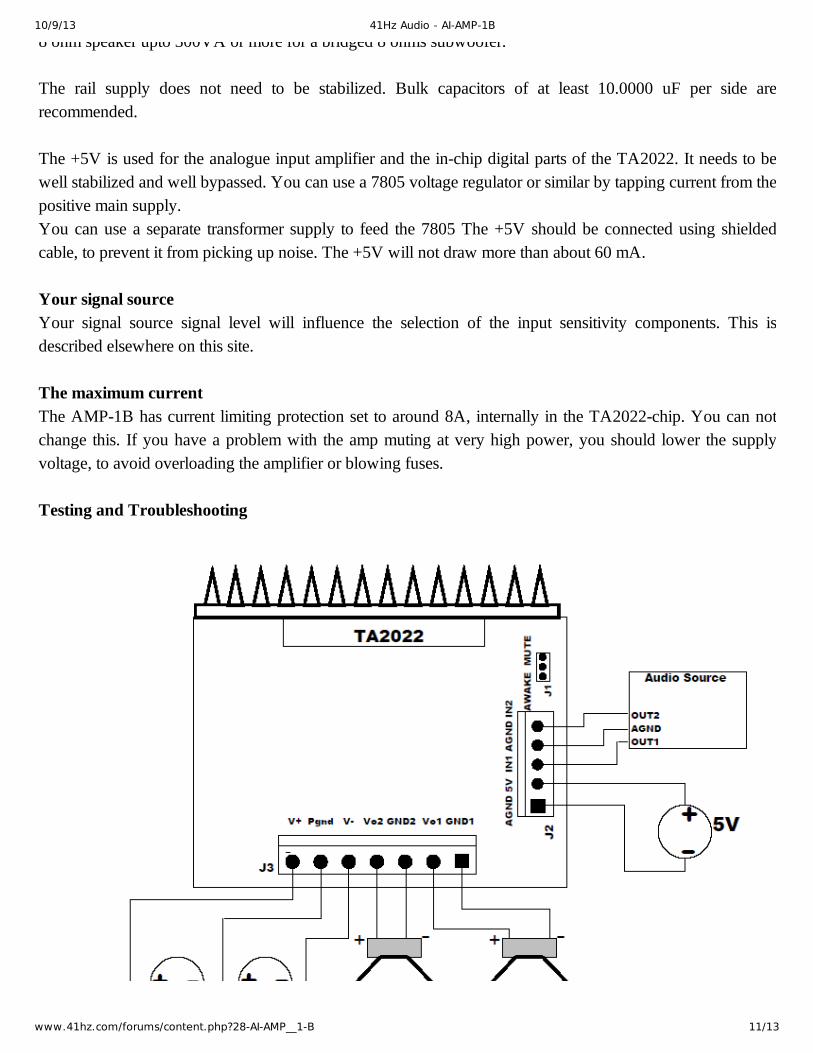
The rail supply does not need to be stabilized. Bulk capacitors of at least 10.0000 uF per side arerecommended.
The +5V is used for the analogue input amplifier and the inchip digital parts of the TA2022. It needs to bewell stabilized and well bypassed. You can use a 7805 voltage regulator or similar by tapping current from thepositive main supply. You can use a separate transformer supply to feed the 7805 The +5V should be connected using shieldedcable, to prevent it from picking up noise. The +5V will not draw more than about 60 mA.
Your signal sourceYour signal source signal level will influence the selection of the input sensitivity components. This isdescribed elsewhere on this site.
The maximum currentThe AMP1B has current limiting protection set to around 8A, internally in the TA2022chip. You can notchange this. If you have a problem with the amp muting at very high power, you should lower the supplyvoltage, to avoid overloading the amplifier or blowing fuses.
Testing and Troubleshooting
10/9/13 41Hz Audio - AI-AMP-1B
www.41hz.com/forums/content.php?28-AI-AMP__1-B 12/13
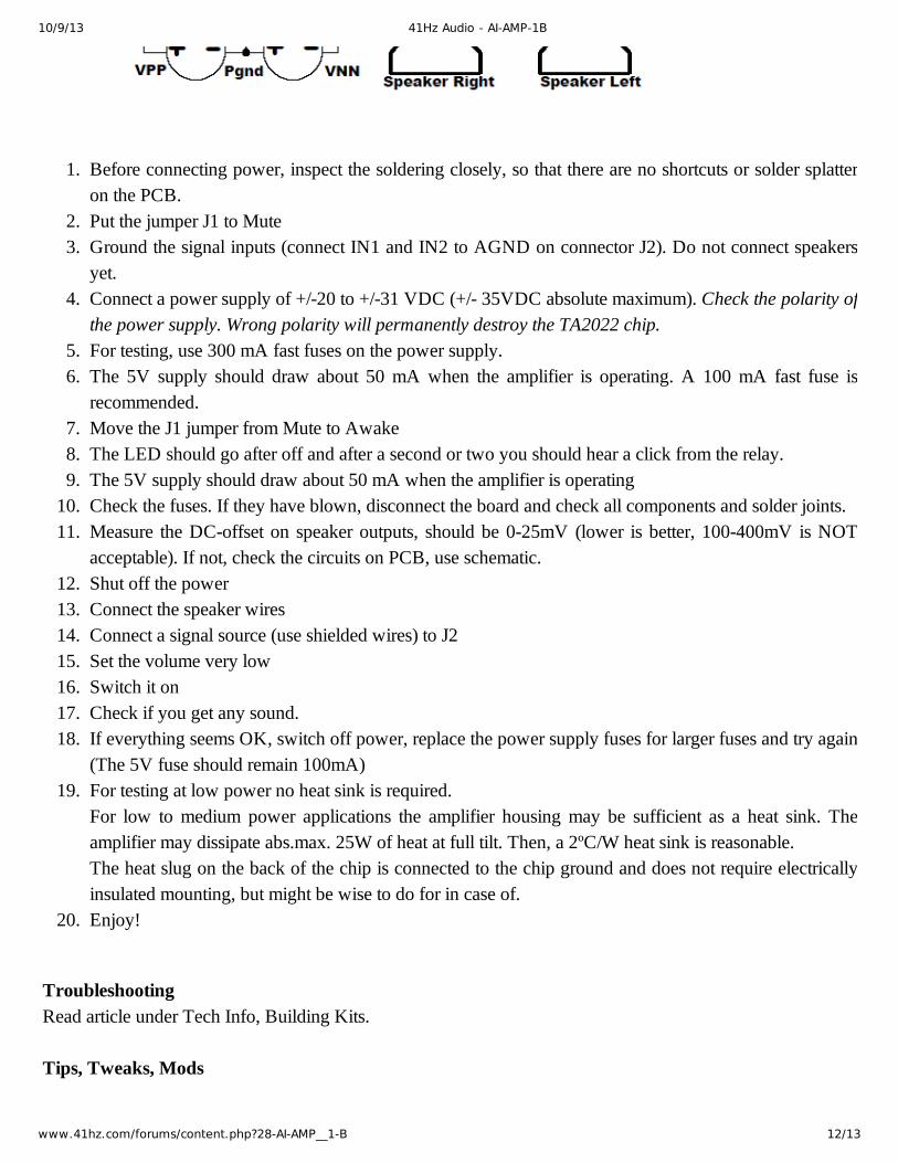
1. Before connecting power, inspect the soldering closely, so that there are no shortcuts or solder splatteron the PCB.
2. Put the jumper J1 to Mute3. Ground the signal inputs (connect IN1 and IN2 to AGND on connector J2). Do not connect speakers
yet.4. Connect a power supply of +/20 to +/31 VDC (+/ 35VDC absolute maximum). Check the polarity ofthe power supply. Wrong polarity will permanently destroy the TA2022 chip.
5. For testing, use 300 mA fast fuses on the power supply.6. The 5V supply should draw about 50 mA when the amplifier is operating. A 100 mA fast fuse is
recommended.7. Move the J1 jumper from Mute to Awake8. The LED should go after off and after a second or two you should hear a click from the relay.9. The 5V supply should draw about 50 mA when the amplifier is operating10. Check the fuses. If they have blown, disconnect the board and check all components and solder joints.11. Measure the DCoffset on speaker outputs, should be 025mV (lower is better, 100400mV is NOT
acceptable). If not, check the circuits on PCB, use schematic.12. Shut off the power13. Connect the speaker wires14. Connect a signal source (use shielded wires) to J215. Set the volume very low16. Switch it on17. Check if you get any sound.18. If everything seems OK, switch off power, replace the power supply fuses for larger fuses and try again
(The 5V fuse should remain 100mA)19. For testing at low power no heat sink is required.
For low to medium power applications the amplifier housing may be sufficient as a heat sink. Theamplifier may dissipate abs.max. 25W of heat at full tilt. Then, a 2ºC/W heat sink is reasonable. The heat slug on the back of the chip is connected to the chip ground and does not require electricallyinsulated mounting, but might be wise to do for in case of.
20. Enjoy!
TroubleshootingRead article under Tech Info, Building Kits.
Tips, Tweaks, Mods

10/9/13 41Hz Audio - AI-AMP-1B
www.41hz.com/forums/content.php?28-AI-AMP__1-B 13/13
Please be advised that this amplifier module is a 'core' module. So secondary circuits should be added, like apowersupply, input protection, volume control, etc.
AMP1x BridgingUnder Tech Info, Building Kits, read article about how to bridge the amp for MAX MONO POWER.
AMP1B revision history
1.02.03.04.0
AMP1 views (NOT AMP1B)Read article under Tech Info, Misc. for some buildpictures..
www.41hz.com
http://www.41hz.com/forums/content.php?28-AI-AMP__1-B
http://goo.gl/ffgS