4100900-30 - installation instructions - case 23xx hyd
TRANSCRIPT

8/6/2019 4100900-30 - Installation Instructions - CASE 23xx HYD
http://slidepdf.com/reader/full/4100900-30-installation-instructions-case-23xx-hyd 1/116
GPS AutoSteer System
Installation Manual
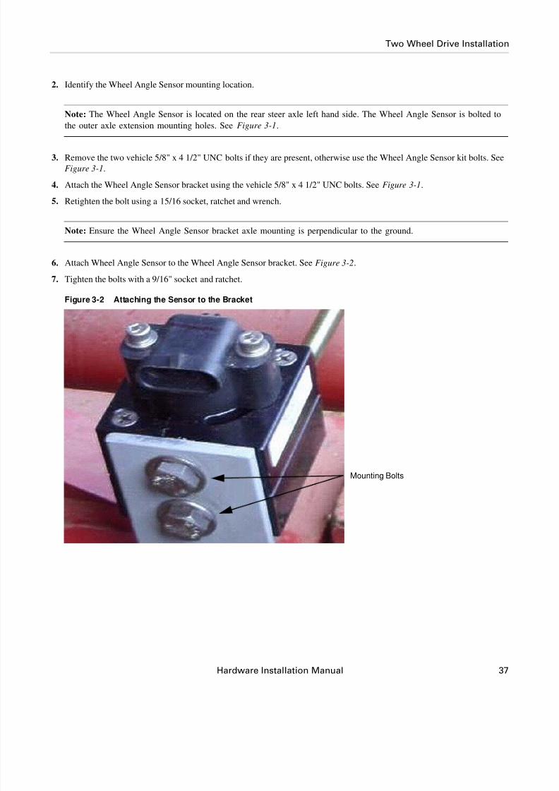
Supported Vehicles
Case 2166 Combines
Case 2366 Combines
Case 2188 Combines
Case 2388 Combines
PN: 602-0225-01-A

8/6/2019 4100900-30 - Installation Instructions - CASE 23xx HYD
http://slidepdf.com/reader/full/4100900-30-installation-instructions-case-23xx-hyd 2/116
ii GPS AutoSteer System
LEGAL DISCLAIMER
Note: Read and follow ALL instructions in this manual carefully before installing or operating the AutoSteer system.
Note: Take careful note of the safety information in the Safety Information section and throughout this manual.
The manufacturer disclaims any liability for damage or injury that results from failure to follow the instructions and warnings
set forth herein.
Please take special note of the following warnings:
1. There is NO obstacle avoidance system included in the manufacturer’s product. Therefore, users must always have an
operator on the equipment when the AutoSteer system is in use to look for any obstacles including people, animals, trees,
ditches, buildings, etc.
2. During installation of the AutoSteer system and during the Calibration and Tuning processes the vehicle AutoSteer systemturns the wheel automatically and the vehicle wheels or tracks move. Be sure that all people and obstacles are clear of the
vehicle before engine startup, calibration, tuning or use of the AutoSteer system.
3. Use of the AutoSteer system is NOT permitted while the vehicle is on public roads or in public areas. Ensure that the sys-
tem is OFF before driving on roads or in public areas.
8/6/2019 4100900-30 - Installation Instructions - CASE 23xx HYD
http://slidepdf.com/reader/full/4100900-30-installation-instructions-case-23xx-hyd 3/116
Hardware Installation Manual iii
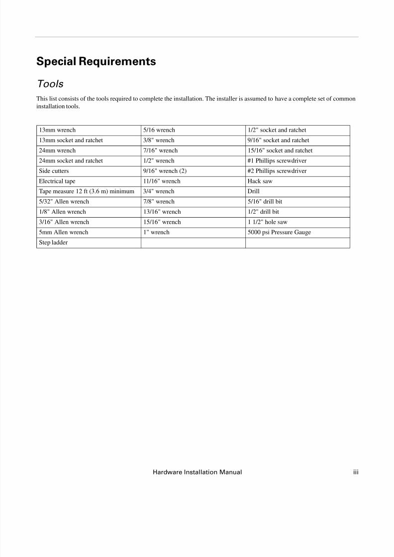
Special Requirements
Tools
This list consists of the tools required to complete the installation. The installer is assumed to have a complete set of commoninstallation tools.
13mm wrench 5/16 wrench 1/2" socket and ratchet
13mm socket and ratchet 3/8" wrench 9/16" socket and ratchet
24mm wrench 7/16" wrench 15/16" socket and ratchet
24mm socket and ratchet 1/2" wrench #1 Phillips screwdriver
Side cutters 9/16" wrench (2) #2 Phillips screwdriver
Electrical tape 11/16" wrench Hack saw
Tape measure 12 ft (3.6 m) minimum 3/4" wrench Drill
5/32" Allen wrench 7/8" wrench 5/16" drill bit
1/8" Allen wrench 13/16" wrench 1/2" drill bit
3/16" Allen wrench 15/16" wrench 1 1/2" hole saw
5mm Allen wrench 1" wrench 5000 psi Pressure Gauge
Step ladder
8/6/2019 4100900-30 - Installation Instructions - CASE 23xx HYD
http://slidepdf.com/reader/full/4100900-30-installation-instructions-case-23xx-hyd 4/116
iv GPS AutoSteer System
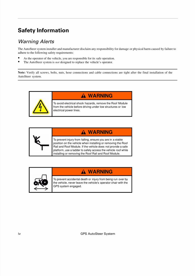
Safety Information
Warning Alerts
The AutoSteer system installer and manufacturer disclaim any responsibility for damage or physical harm caused by failure toadhere to the following safety requirements:
• As the operator of the vehicle, you are responsible for its safe operation.
• The AutoSteer system is not designed to replace the vehicle’s operator.
Note: Verify all screws, bolts, nuts, hose connections and cable connections are tight after the final installation of the
AutoSteer system.
WARNINGTo avoid electrical shock hazards, remove the Roof Module
from the vehicle before driving under low structures or low
electrical power lines.
WARNING
To prevent injury from falling, ensure you are in a stable
position on the vehicle when installing or removing the Roof
Rail and Roof Module. If the vehicle does not provide a safe
platform, use a ladder to safely access the vehicle roof while
installing or removing the Roof Rail and Roof Module.
WARNING
To prevent accidental death or injury from being run over by
the vehicle, never leave the vehicle's operator chair with the
GPS system engaged.

8/6/2019 4100900-30 - Installation Instructions - CASE 23xx HYD
http://slidepdf.com/reader/full/4100900-30-installation-instructions-case-23xx-hyd 5/116
Hardware Installation Manual v
WARNING
High-Pressure Fluid Hazard
Read the Owner’s Manual before installation. Wear handand eye protection while performing hydraulic system
maintenance. Relieve hydraulic system pressure before
servicing the hydraulic system.
WARNING
To understand the potential hazards associated with the
operation of AutoSteer equipment read the provided
documentation before installing the AutoSteer system on a
vehicle.
WARNING
To prevent the accidental engagement of AutoSteer system
and loss of vehicle control while driving on roads, shut down
the AutoSteer system (exit the program). Never drive on
roads or in public areas with the AutoSteer system turned
on.

8/6/2019 4100900-30 - Installation Instructions - CASE 23xx HYD
http://slidepdf.com/reader/full/4100900-30-installation-instructions-case-23xx-hyd 6/116
vi GPS AutoSteer System
Caution Alerts
The AutoSteer system installer and manufacturer disclaim any responsibility for damage or physical harm caused by failure to
adhere to the following safety requirements:
CAUTION
The Roof Module must be removed when transporting or
driving the vehicle at speeds above 30 mph (50 km/h). The
Roof Module can possibly detach due to wind loads at
higher speeds.
CAUTION
The AutoSteer system does not detect obstacles in the
vehicle’s path. The operator must observe the path being
driven in order to avoid obstacles.
CAUTION
When engaged, the AutoSteer controls only the steering of
the vehicle. The operator must control the speed of the
vehicle.
CAUTION
The AutoSteer must be powered OFF when installing or
removing the Roof Module.

8/6/2019 4100900-30 - Installation Instructions - CASE 23xx HYD
http://slidepdf.com/reader/full/4100900-30-installation-instructions-case-23xx-hyd 7/116
Hardware Installation Manual vii
Vehicle RequirementsThe vehicle steering and hydraulic systems must be in good working order before installing the AutoSteer system. Check for
loose or worn parts. Before installing the AutoSteer system drive the vehicle and confirm that it steers straight and the wheels
can be turned from lock to lock. Check the steering system hydraulic hoses and connections to ensure there are no oil leaks.
The vehicle electrical system and battery must be in good working order.
The vehicle should be fully cleaned before installing the AutoSteer system. A clean vehicle improves overall installation and
cable routing and reduces the chance for oil contamination when the hydraulic connections are opened.
CAUTION
The Roof Module must always be firmly secured to the Roof
Rail using the provided hardware whenever the vehicle is inoperation to prevent the Roof Module from releasing from its
bracket and falling.

8/6/2019 4100900-30 - Installation Instructions - CASE 23xx HYD
http://slidepdf.com/reader/full/4100900-30-installation-instructions-case-23xx-hyd 8/116
viii GPS AutoSteer System
Important Information
Note: Verify that all screws, bolts, nuts, cable and hose connections are tight after the AutoSteer system installation.
Technical SupportRefer to your owner's manual for technical support information.
Contact InformationRefer to your owner's manual for contact information.
Copyright © 2009 All Rights Reserved.

8/6/2019 4100900-30 - Installation Instructions - CASE 23xx HYD
http://slidepdf.com/reader/full/4100900-30-installation-instructions-case-23xx-hyd 9/116
Hardware Installation Manual ix
Table of Contents
Chapter 1 Installation Overview.......................................................................................................1
Vehicle Inspection . . . . . . . . . . . . . . . . . . . . . . . . . . . . . . . . . . . . . . . . . . . . . . . . . . . . . . . . . . . 1Installation Procedure Outline . . . . . . . . . . . . . . . . . . . . . . . . . . . . . . . . . . . . . . . . . . . . . . . . . . 2
Kit Overview . . . . . . . . . . . . . . . . . . . . . . . . . . . . . . . . . . . . . . . . . . . . . . . . . . . . . . . . . . . . . . . 3
Assemblies. . . . . . . . . . . . . . . . . . . . . . . . . . . . . . . . . . . . . . . . . . . . . . . . . . . . . . . . . . . . . . . 3
Cable Diagram . . . . . . . . . . . . . . . . . . . . . . . . . . . . . . . . . . . . . . . . . . . . . . . . . . . . . . . . . . . . . 8
Chapter 2 Steering Valve Installation ..............................................................................................9Steering Valve Installation Procedure Overview. . . . . . . . . . . . . . . . . . . . . . . . . . . . . . . . . . . . 9
Hose Kit . . . . . . . . . . . . . . . . . . . . . . . . . . . . . . . . . . . . . . . . . . . . . . . . . . . . . . . . . . . . . . . . . . 10
Steering Valve Configuration . . . . . . . . . . . . . . . . . . . . . . . . . . . . . . . . . . . . . . . . . . . . . . . . . 11
AutoSteer Valve Configuration . . . . . . . . . . . . . . . . . . . . . . . . . . . . . . . . . . . . . . . . . . . . . . 12
Install the Valve Bracket . . . . . . . . . . . . . . . . . . . . . . . . . . . . . . . . . . . . . . . . . . . . . . . . . . . . . 14
Location One Bracket Mounting Procedure . . . . . . . . . . . . . . . . . . . . . . . . . . . . . . . . . . . . 16
Location Two Bracket Mounting Procedure . . . . . . . . . . . . . . . . . . . . . . . . . . . . . . . . . . . . 18Location Three Bracket Mounting Procedure . . . . . . . . . . . . . . . . . . . . . . . . . . . . . . . . . . . 22
Connecting the Hydraulic Hoses . . . . . . . . . . . . . . . . . . . . . . . . . . . . . . . . . . . . . . . . . . . . . . . 25
Steering Valve Installation Checklist . . . . . . . . . . . . . . . . . . . . . . . . . . . . . . . . . . . . . . . . . . . 34
Chapter 3 Wheel Angle Sensor (WAS) Installation.......................................................................35Wheel Angle Sensor Installation Procedures. . . . . . . . . . . . . . . . . . . . . . . . . . . . . . . . . . . . . . 35
Two Wheel Drive Installation . . . . . . . . . . . . . . . . . . . . . . . . . . . . . . . . . . . . . . . . . . . . . . . 35
Four Wheel Drive Installation . . . . . . . . . . . . . . . . . . . . . . . . . . . . . . . . . . . . . . . . . . . . . . . 51
Chapter 4 SA Module Installation ..................................................................................................71Installation Procedure . . . . . . . . . . . . . . . . . . . . . . . . . . . . . . . . . . . . . . . . . . . . . . . . . . . . . . . 71
Chapter 5 Roof Module Installation................................................................................................75Safety Notes . . . . . . . . . . . . . . . . . . . . . . . . . . . . . . . . . . . . . . . . . . . . . . . . . . . . . . . . . . . . . . . 75
Installation Procedure . . . . . . . . . . . . . . . . . . . . . . . . . . . . . . . . . . . . . . . . . . . . . . . . . . . . . . . 76
Chapter 6 Display Installation.........................................................................................................81
Chapter 7 Connecting System Cables............................................................................................85SA Module Harness . . . . . . . . . . . . . . . . . . . . . . . . . . . . . . . . . . . . . . . . . . . . . . . . . . . . . . . . . 85
SA Module Connection . . . . . . . . . . . . . . . . . . . . . . . . . . . . . . . . . . . . . . . . . . . . . . . . . . . . 86
AutoSteer Wheel Angle Sensor Connection . . . . . . . . . . . . . . . . . . . . . . . . . . . . . . . . . . . . 88
Steering Valve Connection . . . . . . . . . . . . . . . . . . . . . . . . . . . . . . . . . . . . . . . . . . . . . . . . . 90
Main Cable Harness . . . . . . . . . . . . . . . . . . . . . . . . . . . . . . . . . . . . . . . . . . . . . . . . . . . . . . . . 92
Roof Module . . . . . . . . . . . . . . . . . . . . . . . . . . . . . . . . . . . . . . . . . . . . . . . . . . . . . . . . . . . . 92
Display. . . . . . . . . . . . . . . . . . . . . . . . . . . . . . . . . . . . . . . . . . . . . . . . . . . . . . . . . . . . . . . . . 95Power Supply Connection . . . . . . . . . . . . . . . . . . . . . . . . . . . . . . . . . . . . . . . . . . . . . . . . . . . . 95
12V Cab Power Outlet. . . . . . . . . . . . . . . . . . . . . . . . . . . . . . . . . . . . . . . . . . . . . . . . . . . . . 96
Battery Power Connection. . . . . . . . . . . . . . . . . . . . . . . . . . . . . . . . . . . . . . . . . . . . . . . . . . 98
Install Warning Label. . . . . . . . . . . . . . . . . . . . . . . . . . . . . . . . . . . . . . . . . . . . . . . . . . . . . . . . 98
Chapter 8 Post-Installation Procedures and Information...........................................................101Verify the Vehicle is Ready for AutoSteer . . . . . . . . . . . . . . . . . . . . . . . . . . . . . . . . . . . . . . 101

8/6/2019 4100900-30 - Installation Instructions - CASE 23xx HYD
http://slidepdf.com/reader/full/4100900-30-installation-instructions-case-23xx-hyd 10/116
x GPS AutoSteer System
Calibration and Tuning Notes . . . . . . . . . . . . . . . . . . . . . . . . . . . . . . . . . . . . . . . . . . . . . . . . 101
Adjusting the AutoSteer Relief Valve . . . . . . . . . . . . . . . . . . . . . . . . . . . . . . . . . . . . . . . . . . 102
Chapter 9 Final Hardware Installation Checklist.........................................................................105

8/6/2019 4100900-30 - Installation Instructions - CASE 23xx HYD
http://slidepdf.com/reader/full/4100900-30-installation-instructions-case-23xx-hyd 11/116
Hardware Installation Manual 1
1
Installation Overview
This Installation Overview chapter contains part numbers, kit overview diagram, cabling diagram and the installation
procedure for the Case Combine AutoSteer Kit.
• Vehicle Inspection
• Installation Procedure Outline
• Kit Overview
• Assemblies
• Bracket Kit Components
• AutoSteer Common K it Components
• Hose Kit Components
• Cable Diagram
This installation guide describes the AutoSteer system installation on several models as shown on the front cover of this
manual. The AutoSteer installation kit PN: 188-0036-01 is used on these vehicle series.
Note: If you are installing an electric steering wheel actuator such as OnTrac II, skip the SA Module, AutoSteer Valve
connection and System Cable connection installation procedures provided in this manual. Refer to your electric steering
product manual for additional instructions.
Vehicle InspectionBefore beginning the AutoSteer system installation confirm the vehicle steering system is in good working order. Drive the
vehicle and verify the vehicle is in correct working order. Also, ensure the following system operations and components:
• Verify you can turn the vehicle.
• Ensure the vehicle steers straight.
• Check for loose or worn steering components.
• Check for hydraulic fluid leaks throughout the system.
• Ensure the hydraulic fluid level is correct.
• Service the vehicle if the steering is not in good working order.
8/6/2019 4100900-30 - Installation Instructions - CASE 23xx HYD
http://slidepdf.com/reader/full/4100900-30-installation-instructions-case-23xx-hyd 12/116
2 GPS AutoSteer System
Installation Procedure Outline
Installation Procedure Outline1. Verify shipped components.
2. Install the Hydraulic Valve Assembly.
3. Install the Hydraulic Hoses.
4. Install the Wheel Angle Sensor.
5. Install the SA Module.
6. Install the Roof module.
7. Install the User Terminal.
8. Install the Main Cable Harness and SA Module Harness.
9. Ensure all connectors are properly coupled.
10. Power ON the system.
11. Calibrate the tractor.
12. Tune the tractor.
13. Verify installation and system operation.

8/6/2019 4100900-30 - Installation Instructions - CASE 23xx HYD
http://slidepdf.com/reader/full/4100900-30-installation-instructions-case-23xx-hyd 13/116
Hardware Installation Manual 3
Kit Overview
Kit Overview
Figure 1-1 Installation Kit Components (PN: 188-0036-01)
Table 1-1 Installation Kit Components (PN: 188-0036-01)
Assemblies
• Bracket Kit Components
• AutoSteer Common K it Components
• Hose Kit Components
Item Component Part Number
1. Bracket Kit 152-0029-01
2. Common Kit 153-0001-01
3. Hose Kit 500-0351-01
8/6/2019 4100900-30 - Installation Instructions - CASE 23xx HYD
http://slidepdf.com/reader/full/4100900-30-installation-instructions-case-23xx-hyd 14/116
4 GPS AutoSteer System
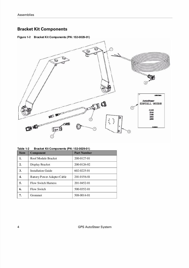
Assemblies
Bracket Kit Components
Figure 1-2 Bracket Kit Components (PN: 152-0029-01)
Table 1-2 Bracket Kit Components (PN: 152-0029-01)
Item Component Part Number
1. Roof Module Bracket 200-0127-01
2. Display Bracket 200-0126-02
3. Installation Guide 602-0225-01
4. Battery Power Adapter Cable 201-0156-01
5. Flow Switch Harness 201-0452-01
6. Flow Switch 500-0352-01
7. Grommet 508-0014-01
8/6/2019 4100900-30 - Installation Instructions - CASE 23xx HYD
http://slidepdf.com/reader/full/4100900-30-installation-instructions-case-23xx-hyd 15/116
Hardware Installation Manual 5
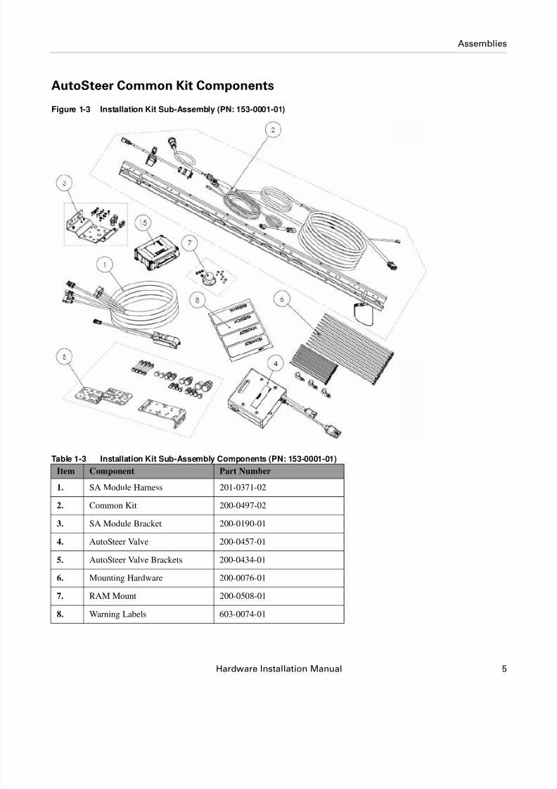
Assemblies
AutoSteer Common Kit Components
Figure 1-3 Installation Kit Sub-Assembly (PN: 153-0001-01)
Table 1-3 Installation Kit Sub-Assembly Components (PN: 153-0001-01)
Item Component Part Number
1. SA Module Harness 201-0371-02
2. Common Kit 200-0497-02
3. SA Module Bracket 200-0190-01
4. AutoSteer Valve 200-0457-01
5. AutoSteer Valve Brackets 200-0434-01
6. Mounting Hardware 200-0076-01
7. RAM Mount 200-0508-01
8. Warning Labels 603-0074-01

8/6/2019 4100900-30 - Installation Instructions - CASE 23xx HYD
http://slidepdf.com/reader/full/4100900-30-installation-instructions-case-23xx-hyd 16/116
6 GPS AutoSteer System
Assemblies
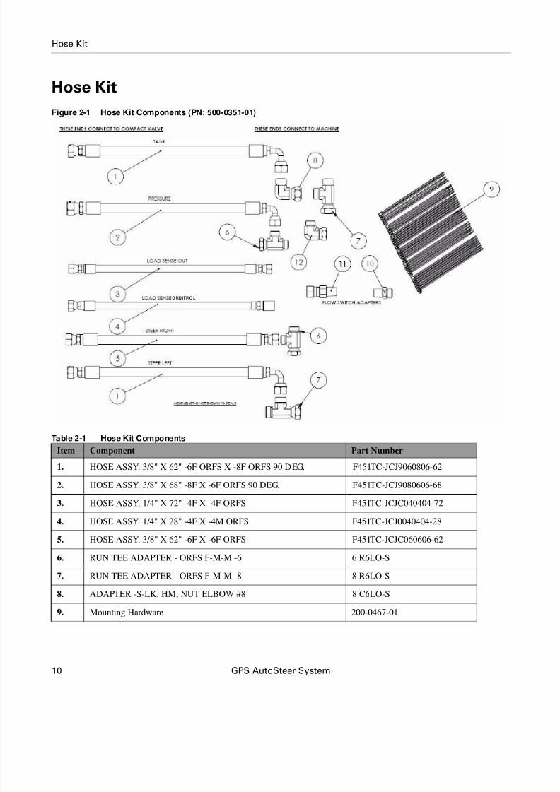
Hose Kit Components
Figure 1-4 Hose Kit Components (PN: 500-0351-01)
Table 1-4 Hose Kit Components
15. SA Module Assembly 200-0206-01
Item Component Part Number
1. HOSE ASSY. 3/8" X 62" -6F ORFS X -8F ORFS 90 DEG. F451TC-JCJ9060806-62
2. HOSE ASSY. 3/8" X 68" -8F X -6F ORFS 90 DEG. F451TC-JCJ9080606-68
3. HOSE ASSY. 1/4" X 72" -4F X -4F ORFS F451TC-JCJC040404-72
4. HOSE ASSY. 1/4" X 28" -4F X -4M ORFS F451TC-JCJ0040404-28
5. HOSE ASSY. 3/8" X 62" -6F X -6F ORFS F451TC-JCJC060606-62
6. RUN TEE ADAPTER - ORFS F-M-M -6 6 R6LO-S
7. RUN TEE ADAPTER - ORFS F-M-M -8 8 R6LO-S
Item Component Part Number

8/6/2019 4100900-30 - Installation Instructions - CASE 23xx HYD
http://slidepdf.com/reader/full/4100900-30-installation-instructions-case-23xx-hyd 17/116
Hardware Installation Manual 7
Assemblies
8. ADAPTER -S-LK, HM, NUT ELBOW #8 8 C6LO-S
9. Mounting Hardware 200-0467-01
10. STRAIGHT ADAPTER 3/8"M NPT X -6M ORFS 6-6 FLO-S
11. SWIVEL ADAPTER 3/8"M NPT -6F ORFS 6-6 F6L-S
12. Elbow Adapter 6 C6LO-S
Item Component Part Number

8/6/2019 4100900-30 - Installation Instructions - CASE 23xx HYD
http://slidepdf.com/reader/full/4100900-30-installation-instructions-case-23xx-hyd 18/116
8 GPS AutoSteer System
Cable Diagram
Cable Diagram

8/6/2019 4100900-30 - Installation Instructions - CASE 23xx HYD
http://slidepdf.com/reader/full/4100900-30-installation-instructions-case-23xx-hyd 19/116
Hardware Installation Manual 9
2
Steering Valve Installation
This Steering Valve Installation chapter information is provided in the following sections:
• Steering Valve Installation Procedure Overview
• Hose Kit
• Steering Valve Configuration
• AutoSteer Valve Con figuration
• Install the Valve Bracket
• Connecting the Hydraulic Hoses
• Steering Valve Installation Checklist
Steering Valve Installation Procedure Overview
Note: You can use a fiberglass cable puller to make it easier to pull the hydraulic hoses and electrical cables through and
around the vehicle.
1. Ensure the valve plug and orifice configuration is correct before installing the AutoSteer valve.
Note: See the AutoSteer Valve Configurationsection for valve plug and orifice configuration information.
2. Install the AutoSteer valve bracket and valve on the vehicle.
3. Connect the six hoses between the valve and the vehicle steering system.
4. Check for oil leaks.
5. Adjust the AutoSteer pressure relief valve.
6. Perform a functional test to confirm correct valve operation.
WARNINGHigh-Pressure Fluid Hazard
Read the Owner’s Manual before installation. Wear hand
and eye protection while performing hydraulic system
maintenance. Relieve hydraulic system pressure before
servicing the hydraulic system.
8/6/2019 4100900-30 - Installation Instructions - CASE 23xx HYD
http://slidepdf.com/reader/full/4100900-30-installation-instructions-case-23xx-hyd 20/116
10 GPS AutoSteer System
Hose Kit
Hose Kit
Figure 2-1 Hose Kit Components (PN: 500-0351-01)
Table 2-1 Hose Kit Components
Item Component Part Number
1. HOSE ASSY. 3/8" X 62" -6F ORFS X -8F ORFS 90 DEG. F451TC-JCJ9060806-62
2. HOSE ASSY. 3/8" X 68" -8F X -6F ORFS 90 DEG. F451TC-JCJ9080606-68
3. HOSE ASSY. 1/4" X 72" -4F X -4F ORFS F451TC-JCJC040404-72
4. HOSE ASSY. 1/4" X 28" -4F X -4M ORFS F451TC-JCJ0040404-28
5. HOSE ASSY. 3/8" X 62" -6F X -6F ORFS F451TC-JCJC060606-62
6. RUN TEE ADAPTER - ORFS F-M-M -6 6 R6LO-S
7. RUN TEE ADAPTER - ORFS F-M-M -8 8 R6LO-S
8. ADAPTER -S-LK, HM, NUT ELBOW #8 8 C6LO-S
9. Mounting Hardware 200-0467-01

8/6/2019 4100900-30 - Installation Instructions - CASE 23xx HYD
http://slidepdf.com/reader/full/4100900-30-installation-instructions-case-23xx-hyd 21/116
Hardware Installation Manual 11
Steering Valve Configuration
Steering Valve Configuration1. Use a 3/16” Allen key to remove the four cover screws. See Figure 2-2.
2. Remove the front cover to access the hose connections, pressure transducer and relief valve. See Figure 2-2.
Figure 2-2 Steering Valve Assembly
Note: Figure 2-3 shows the Steering Valve assembly hydraulic connection functions.
10. STRAIGHT ADAPTER 3/8"M NPT X -6M ORFS 6-6 FLO-S
11. SWIVEL ADAPTER 3/8"M NPT -6F ORFS 6-6 F6L-S
12. Elbow Adapter 6 C6LO-S
Item Component Part Number

8/6/2019 4100900-30 - Installation Instructions - CASE 23xx HYD
http://slidepdf.com/reader/full/4100900-30-installation-instructions-case-23xx-hyd 22/116
8/6/2019 4100900-30 - Installation Instructions - CASE 23xx HYD
http://slidepdf.com/reader/full/4100900-30-installation-instructions-case-23xx-hyd 23/116
Hardware Installation Manual 13
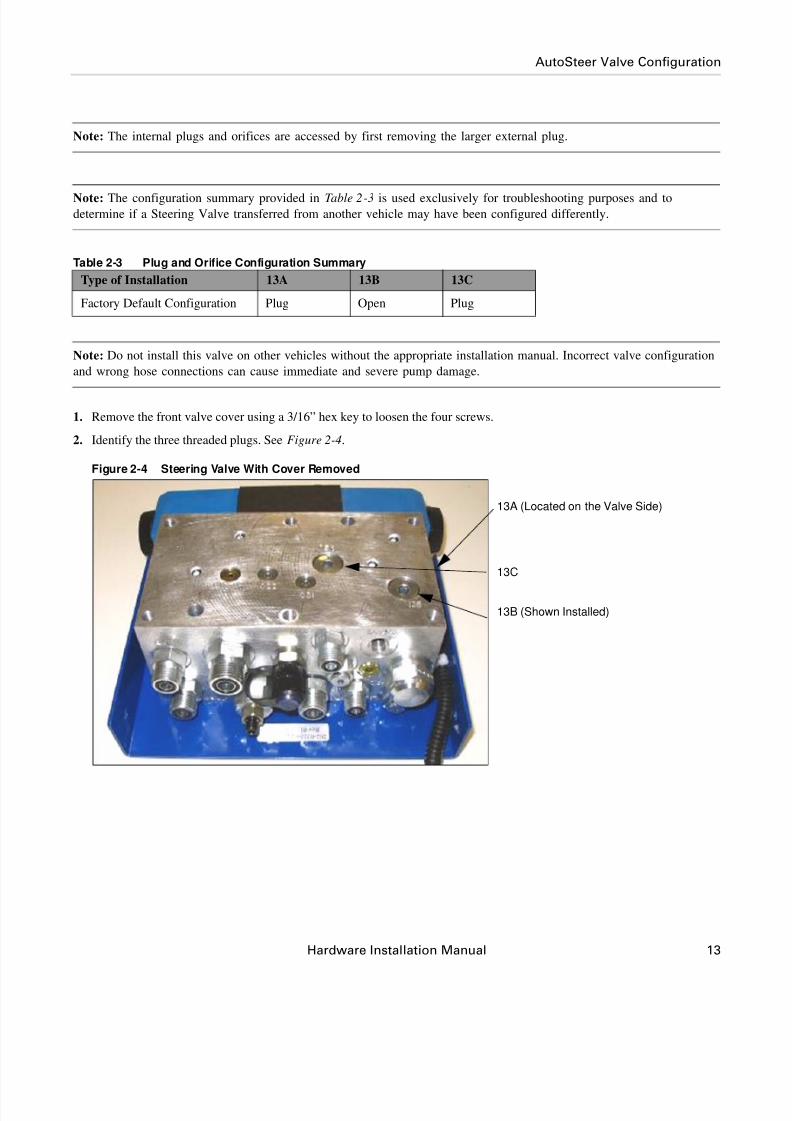
AutoSteer Valve Configuration
Note: The internal plugs and orifices are accessed by first removing the larger external plug.
Note: The configuration summary provided in Table 2-3 is used exclusively for troubleshooting purposes and todetermine if a Steering Valve transferred from another vehicle may have been configured differently.
Table 2-3 Plug and Orifice Configuration Summary
Note: Do not install this valve on other vehicles without the appropriate installation manual. Incorrect valve configuration
and wrong hose connections can cause immediate and severe pump damage.
1. Remove the front valve cover using a 3/16” hex key to loosen the four screws.
2. Identify the three threaded plugs. See Figure 2-4.
Figure 2-4 Steering Valve With Cover Removed
Type of Installation 13A 13B 13C
Factory Default Configuration Plug Open Plug
13A (Located on the Valve Side)
13C
13B (Shown Installed)

8/6/2019 4100900-30 - Installation Instructions - CASE 23xx HYD
http://slidepdf.com/reader/full/4100900-30-installation-instructions-case-23xx-hyd 24/116
14 GPS AutoSteer System
Install the Valve Bracket
3. Identify the large external access plug identified in position 13B.
4. Remove the external plug in position 13B using a 1/4” hex key. See Figure 2-5.
Figure 2-5 Removing External Plug
5. Confirm there is no internal plug installed in position 13B.
6. If present, remove the internal plug in the 13B position using a 1/8” hex key.
7. Re-install the large external plug in position 13B.
8. Repeat Step 3. through Step 7. for the 13A and 13C plug and orifice positions.
9. This concludes the plug and orifice verification. The valve is now ready for vehicle installation.
Install the Valve BracketThe AutoSteer valve can be installed in different vehicle frame locations. Figure 2-6 shows one location for valve installation.
You should choose a protected location which enables short hose routing to the vehicle connection points and is readily
accessible for installation and maintenance purposes.
Note: Figure 2-6 through Figure 2-8 show various valve bracket mounting locations.
Use the bracket installation procedure for the specific combine and vehicle installation location shown below.
• AutoSteer Valve Location 1 (2166 combines)
• AutoSteer Valve Location 2 (2388 and (2166 without accumulator) combines)
• AutoSteer Valve Location 3 (2166 - 2388 combines)
External Plug

8/6/2019 4100900-30 - Installation Instructions - CASE 23xx HYD
http://slidepdf.com/reader/full/4100900-30-installation-instructions-case-23xx-hyd 25/116
Hardware Installation Manual 15
Install the Valve Bracket
Figure 2-6 AutoSteer Valve Location 1 (2166 combines)
Figure 2-7 AutoSteer Valve Location 2 (2388 and (2166 without accumulator) combines)
Bracket Location 1
Bracket Location 2

8/6/2019 4100900-30 - Installation Instructions - CASE 23xx HYD
http://slidepdf.com/reader/full/4100900-30-installation-instructions-case-23xx-hyd 26/116
16 GPS AutoSteer System
Location One Bracket Mounting Procedure
Figure 2-8 AutoSteer Valve Location 3 (2166 - 2388 combines)
Location One Bracket Mounting Procedure
1. Remove nuts shown in Figure 2-9 using 3/4”socket and ratchet.
Figure 2-9 Valve Bracket Mounting Bolts
Drilled Hole
Existing Hole
Bracket Location
Bracket Bolts

8/6/2019 4100900-30 - Installation Instructions - CASE 23xx HYD
http://slidepdf.com/reader/full/4100900-30-installation-instructions-case-23xx-hyd 27/116
Hardware Installation Manual 17
Location One Bracket Mounting Procedure
2. Mount the L bracket on the bolts. See Figure 2-10.
3. Replace and tighten the nuts.
Figure 2-10 Mounting the Valve Bracket
4. Mount the steering valve to L bracket. See Figure 2-11.
5. Insert the four valve bracket bolts and tighten using 1/2" wrench. See Figure 2-11.
Figure 2-11 Mounted Valve Bracket
Mounting Bolts
Mounting Bolts

8/6/2019 4100900-30 - Installation Instructions - CASE 23xx HYD
http://slidepdf.com/reader/full/4100900-30-installation-instructions-case-23xx-hyd 28/116
18 GPS AutoSteer System
Location Two Bracket Mounting Procedure
Location Two Bracket Mounting Procedure
1. Remove bolts and nuts above feeder house using a 3/4”socket and ratchet.
Figure 2-12 Mounting Bolt Location
Mounting Bolt Locations

8/6/2019 4100900-30 - Installation Instructions - CASE 23xx HYD
http://slidepdf.com/reader/full/4100900-30-installation-instructions-case-23xx-hyd 29/116
Hardware Installation Manual 19
Location Two Bracket Mounting Procedure
2. Mount the L bracket to valve before installing on the combine using a 1/2" wrench. See Figure 2-13.
Note: Use the bolts supplied in the kit to mount the valve to the bracket. Due to the position required, some of the
L bracket large holes may need to be used. Large washers can be used to ensure proper mounting.
Figure 2-13 Mounting the Bracket to the Valve

8/6/2019 4100900-30 - Installation Instructions - CASE 23xx HYD
http://slidepdf.com/reader/full/4100900-30-installation-instructions-case-23xx-hyd 30/116
20 GPS AutoSteer System
Location Two Bracket Mounting Procedure
3. Mount the L bracket reusing the existing nuts and bolts. See Figure 2-14.
4. Tighten the bolts using a 3/4” socket and ratchet.
Note: The bracket is shown without the valve mounted for ease of viewing the mounting placement.
Figure 2-14 Mounting Valve Bracket

8/6/2019 4100900-30 - Installation Instructions - CASE 23xx HYD
http://slidepdf.com/reader/full/4100900-30-installation-instructions-case-23xx-hyd 31/116
Hardware Installation Manual 21
Location Two Bracket Mounting Procedure
5. The valve is now mounted. See Figure 2-15.
Figure 2-15 Steering Valve Mounted (shown with hoses connected)
8/6/2019 4100900-30 - Installation Instructions - CASE 23xx HYD
http://slidepdf.com/reader/full/4100900-30-installation-instructions-case-23xx-hyd 32/116
22 GPS AutoSteer System
Location Three Bracket Mounting Procedure
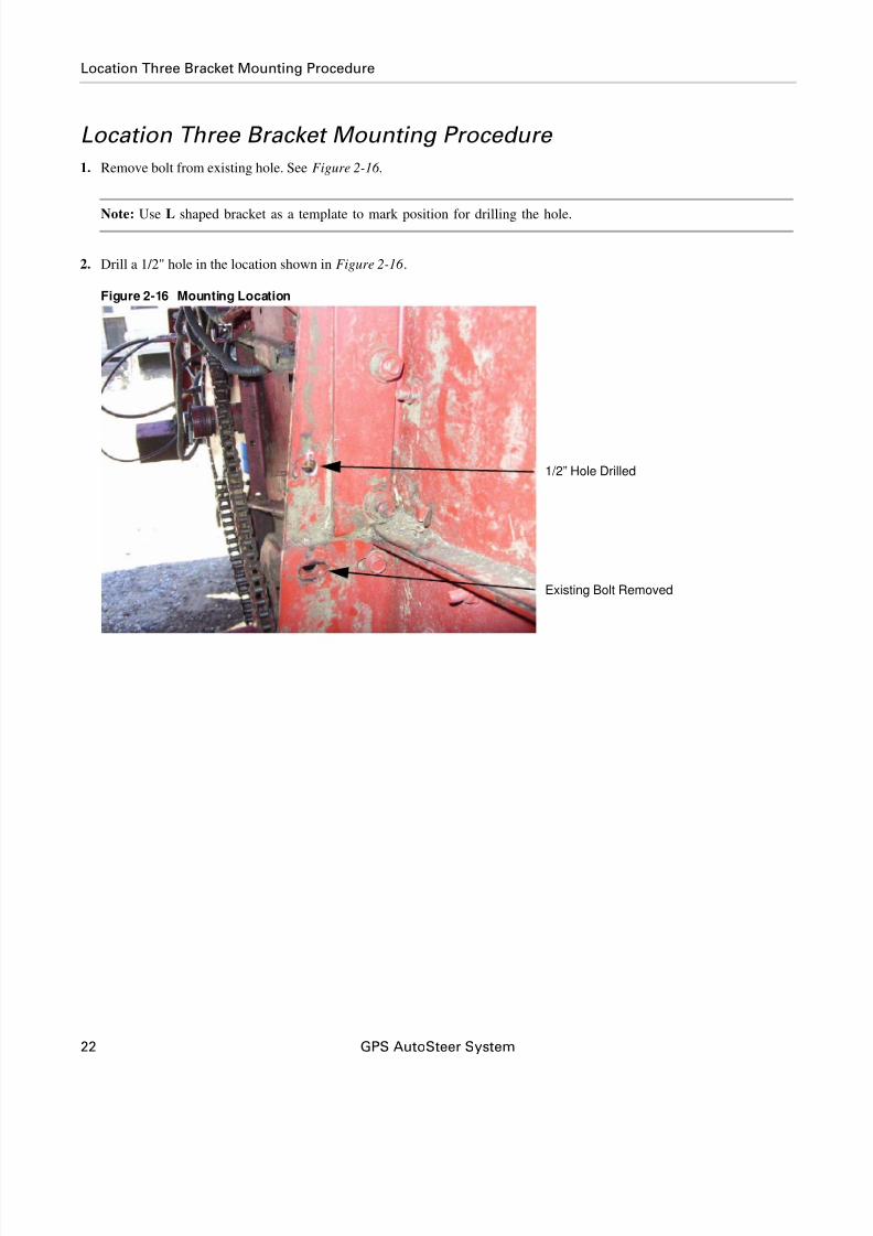
Location Three Bracket Mounting Procedure
1. Remove bolt from existing hole. See Figure 2-16 .
Note: Use L shaped bracket as a template to mark position for drilling the hole.
2. Drill a 1/2" hole in the location shown in Figure 2-16 .
Figure 2-16 Mounting Location
Existing Bolt Removed
1/2” Hole Drilled
8/6/2019 4100900-30 - Installation Instructions - CASE 23xx HYD
http://slidepdf.com/reader/full/4100900-30-installation-instructions-case-23xx-hyd 33/116
Hardware Installation Manual 23
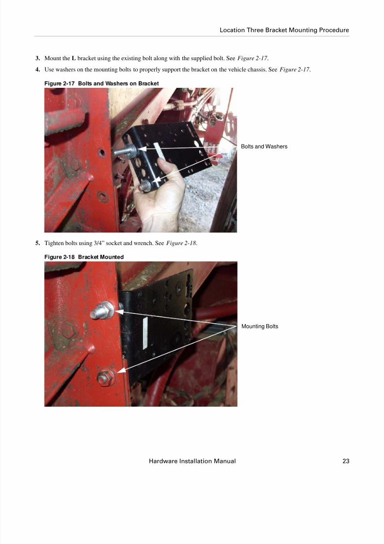
Location Three Bracket Mounting Procedure
3. Mount the L bracket using the existing bolt along with the supplied bolt. See Figure 2-17 .
4. Use washers on the mounting bolts to properly support the bracket on the vehicle chassis. See Figure 2-17 .
Figure 2-17 Bolts and Washers on Bracket
5. Tighten bolts using 3/4” socket and wrench. See Figure 2-18.
Figure 2-18 Bracket Mounted
Bolts and Washers
Mounting Bolts
8/6/2019 4100900-30 - Installation Instructions - CASE 23xx HYD
http://slidepdf.com/reader/full/4100900-30-installation-instructions-case-23xx-hyd 34/116
24 GPS AutoSteer System
Location Three Bracket Mounting Procedure
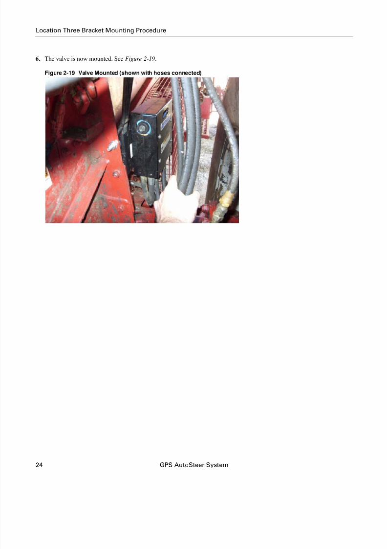
6. The valve is now mounted. See Figure 2-19.
Figure 2-19 Valve Mounted (shown with hoses connected)

8/6/2019 4100900-30 - Installation Instructions - CASE 23xx HYD
http://slidepdf.com/reader/full/4100900-30-installation-instructions-case-23xx-hyd 35/116
Hardware Installation Manual 25
Connecting the Hydraulic Hoses
Connecting the Hydraulic HosesFigure 2-20 shows the combine hydraulic connections before installing the AutoSteer system. Figure 2-21 shows the combine
hydraulic connections after installing the AutoSteer system.
Figure 2-20 Hydraulic Hose Connection Schematic Before AutoSteer Installation

8/6/2019 4100900-30 - Installation Instructions - CASE 23xx HYD
http://slidepdf.com/reader/full/4100900-30-installation-instructions-case-23xx-hyd 36/116
26 GPS AutoSteer System
Connecting the Hydraulic Hoses
Figure 2-21 Hydraulic Hose Connection Schematic After AutoSteer Installation
8/6/2019 4100900-30 - Installation Instructions - CASE 23xx HYD
http://slidepdf.com/reader/full/4100900-30-installation-instructions-case-23xx-hyd 37/116
Hardware Installation Manual 27
Connecting the Hydraulic Hoses
Note: The hoses must be connected in the correct order for best fit and ease of installation.
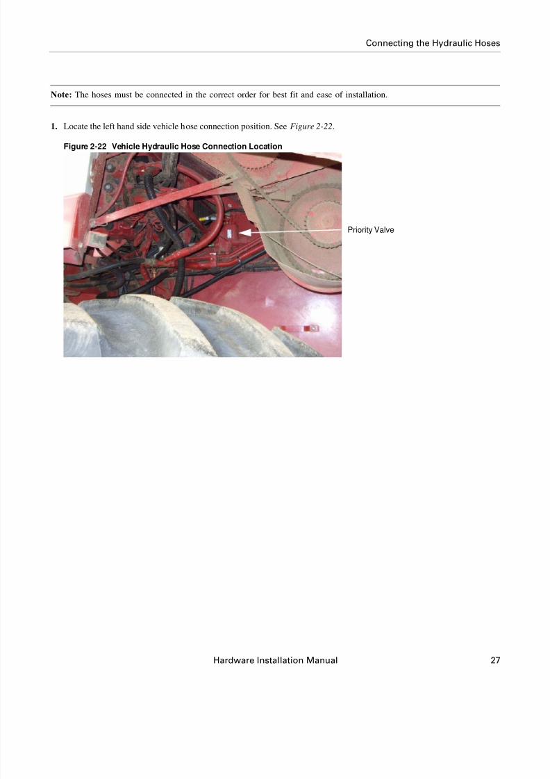
1. Locate the left hand side vehicle hose connection position. See Figure 2-22.
Figure 2-22 Vehicle Hydraulic Hose Connection Location
Priority Valve

8/6/2019 4100900-30 - Installation Instructions - CASE 23xx HYD
http://slidepdf.com/reader/full/4100900-30-installation-instructions-case-23xx-hyd 38/116
28 GPS AutoSteer System
Connecting the Hydraulic Hoses
Note: The pressure and load sense lines are connected to the steering Priority valve. The Pressure line is connected to
the existing pressure line using a 90 degree adapter and a Tee adapter. The 90 degree adapter screws onto the CF port
on the Priority valve. The pressure Tee adapter then screws onto the 90 degree adapter.The Load Sense Out is
connected to the steering Priority valve.
2. Install a 90 degree adapter on the Priority Valve CF port. See Figure 2-23.
3. Install run Tee onto the 90 degree adapter. See Figure 2-23.
4. Connect the end of the AutoSteer Pressure hose to the side of the run Tee. See Figure 2-23.
5. Tighten all the Pressure Port hydraulic hose fittings.
Figure 2-23 Priority Valve Pressure Port Connection
Flow Switch
Run Tee
CF Port
90 Degree Adapter

8/6/2019 4100900-30 - Installation Instructions - CASE 23xx HYD
http://slidepdf.com/reader/full/4100900-30-installation-instructions-case-23xx-hyd 39/116
Hardware Installation Manual 29
Connecting the Hydraulic Hoses
6. Disconnect the Load Sense line from the combine Priority Valve. See Figure 2-24.
7. Connect the combine Load Sense line to the AutoSteer Valve Load Sense Orbitrol Port.
8. Connect the AutoSteer Valve Load Sense Out port to the combine Priority Valve Load Sense port. See Figure 2-24.
Figure 2-24 Priority Valve Load Sense Port
Load Sense Connection

8/6/2019 4100900-30 - Installation Instructions - CASE 23xx HYD
http://slidepdf.com/reader/full/4100900-30-installation-instructions-case-23xx-hyd 40/116
30 GPS AutoSteer System
Connecting the Hydraulic Hoses
9. Connect the other end of the AutoSteer Pressure hose to the PRESS port on the AutoSteer valve.
Note: Only hand tighten the hose fitting on the AutoSteer valve now. You may need to temporarily disconnect the
fitting later in the procedure to make other hydraulic connections to the AutoSteer valve easier.
10. Assemble the in-line pressure flow switch. See Figure 2-25.
Note: The flow switch connects in-line to the Orbitrol Pressure line. Ensure the flow (see arrow on pressure switch) is
going towards the Orbitrol. See Figure 2-25.
Figure 2-25 Orbitrol Pressure Hose In-Line Flow Switch
Flow Switch
Flow Switch Direction Arrow

8/6/2019 4100900-30 - Installation Instructions - CASE 23xx HYD
http://slidepdf.com/reader/full/4100900-30-installation-instructions-case-23xx-hyd 41/116

8/6/2019 4100900-30 - Installation Instructions - CASE 23xx HYD
http://slidepdf.com/reader/full/4100900-30-installation-instructions-case-23xx-hyd 42/116
32 GPS AutoSteer System
Connecting the Hydraulic Hoses
12. Locate the steering line connection points. See Figure 2-27 .
Note: The steering line connection points are located on the combine left hand side behind the drive wheel.
Figure 2-27 Steering Line Connection Points
13. Connect the AutoSteer steering lines to the existing vehicle steering lines using Tee adapters. See Figure 2-28.
Figure 2-28 Steering Lines Tee Adapter Connections
Steering Line Connection Points

8/6/2019 4100900-30 - Installation Instructions - CASE 23xx HYD
http://slidepdf.com/reader/full/4100900-30-installation-instructions-case-23xx-hyd 43/116
Hardware Installation Manual 33
Connecting the Hydraulic Hoses
14. Route the hoses neatly to the AutoSteer valve and secure them using cable ties.
Note: Ensure the hoses are not rubbing on any sharp surfaces or touching any hot vehicle surfaces.
Figure 2-29 Hose Routing Example
15. Remove valve cover by removing four screws using a 3/16 allen wrench.
16. Connect each hose to its correct port.
17. Tighten all the hydraulic hose fittings on each hose end.
18. Install the threaded pressure transducer into the port identified as TRANS.
19. Tighten the pressure transducer using a 3/4 inch wrench.
20. Replace the AutoSteer Valve cover.
21. Insert and tighten the cover screws.
Wire Tie

8/6/2019 4100900-30 - Installation Instructions - CASE 23xx HYD
http://slidepdf.com/reader/full/4100900-30-installation-instructions-case-23xx-hyd 44/116
34 GPS AutoSteer System
Steering Valve Installation Checklist
Steering Valve Installation Checklist1. Valve bracket bolts are tight.
2. Steering valve mounting screws are tight.
3. Pressure hose is connected to the correct port on AutoSteer Valve and Priority Valve.
4. Tank hose is connected to the correct port on AutoSteer Valve and existing vehicle Return line.
5. LS-OUT hose connected to the correct port on AutoSteer Valve and Priority Valve LS port.
6. LS ORBITROL hose is connected to the correct ports at both ends.
7. Right steer hose is connected correctly at both ends.
8. Left steer hose is connected correctly at both ends.
9. Pressure transducer is installed and tight.
10. All hydraulic hose fittings are tight.
11. Hose routing is correct and cable ties are on all hoses.
12. 5000psi pressure gauge is installed on the valve test port.

8/6/2019 4100900-30 - Installation Instructions - CASE 23xx HYD
http://slidepdf.com/reader/full/4100900-30-installation-instructions-case-23xx-hyd 45/116
Hardware Installation Manual 35
3
Wheel Angle Sensor (WAS) Installation
This Wheel Angle Sensor Installation chapter information is provided in the following sections:
• Wheel Angle Sensor Installation Procedures
• Two Wheel Drive Installation
• Mounting Wheel Angle Sensor Hardware
• Cutting Linkage Rods to Length
• Assembling Linkage Rod Hardware
• Attaching and Adjusting Wheel Angle Sensor Linkage Rods
• Four Wheel Drive Installation
• Mounting Wheel Angle Sensor Hardware
• Cutting Linkage Rods to Length
• Assembling Linkage Rod Hardware
• Attaching and Adjusting Wheel Angle Sensor Linkage Rods
Note: The Wheel Angle Sensor is optional equipment and is not provided with the installation kit. The Wheel Angle
Sensor installation instructions are provided for special installations, when required. If additional line acquisition
performance is required, an AutoSteer Wheel Angle Sensor kit is available.
Wheel Angle Sensor Installation ProceduresThere are two distinct installation procedures based upon the type of combine drive train:
• Two Wheel Drive Installation
• Four Wheel Drive Installation
Two Wheel Drive Installation
The Two Wheel Drive AutoSteer Wheel Angle Sensor installation procedure is provided in the following sub-sections:
• Mounting Wheel Angle Sensor Hardware
• Cutting Linkage Rods to Length
• Assembling Linkage Rod Hardware • Attaching and Adjusting Wheel Angle Sensor Linkage Rods
8/6/2019 4100900-30 - Installation Instructions - CASE 23xx HYD
http://slidepdf.com/reader/full/4100900-30-installation-instructions-case-23xx-hyd 46/116
36 GPS AutoSteer System
Two Wheel Drive Installation
Mounting Wheel Angle Sensor Hardware
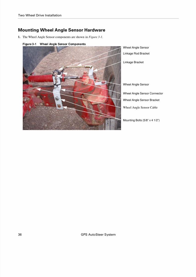
1. The Wheel Angle Sensor components are shown in Figure 3-1.
Figure 3-1 Wheel Angle Sensor Components
Linkage Rod Bracket
Linkage Bracket
Wheel Angle Sensor
Wheel Angle Sensor
Wheel Angle Sensor Bracket
Wheel Angle Sensor Cable
Wheel Angle Sensor Connector
Mounting Bolts (5/8” x 4 1/2”)
8/6/2019 4100900-30 - Installation Instructions - CASE 23xx HYD
http://slidepdf.com/reader/full/4100900-30-installation-instructions-case-23xx-hyd 47/116

8/6/2019 4100900-30 - Installation Instructions - CASE 23xx HYD
http://slidepdf.com/reader/full/4100900-30-installation-instructions-case-23xx-hyd 48/116
38 GPS AutoSteer System
Two Wheel Drive Installation
8. Remove the nuts and bolts holding the drag link assembly to the axle using a 15/16” socket, ratchet and a 15/16” wrench.
Note: Caution must be taken when removing the bolts to ensure the drag link assembly does not fall off.
Note: A breaker bar may be necessary to loosen the bolts.
9. Attach the linkage bracket to the axle using the previously removed bolts. See Figure 3-3.
Figure 3-3 Wheel Angle Sensor Axle Bracket Mounted
Mounting Bolts
8/6/2019 4100900-30 - Installation Instructions - CASE 23xx HYD
http://slidepdf.com/reader/full/4100900-30-installation-instructions-case-23xx-hyd 49/116
Hardware Installation Manual 39
Two Wheel Drive Installation
Cutting Linkage Rods to Length
Note: Before cutting the linkage rods, verify the Wheel Angle Sensor brackets will attach to the vehicle as shown in
this manual and they are attached the correct distance from any reference points shown. If this is not possible, do not
cut the rods until it is determined if these lengths will work for your installation. Due to possible variations in the
mounting positions, these measurements could be different. These measurements are provided as a reference only. The
installer is responsible for ensuring the rods are cut to the proper length.
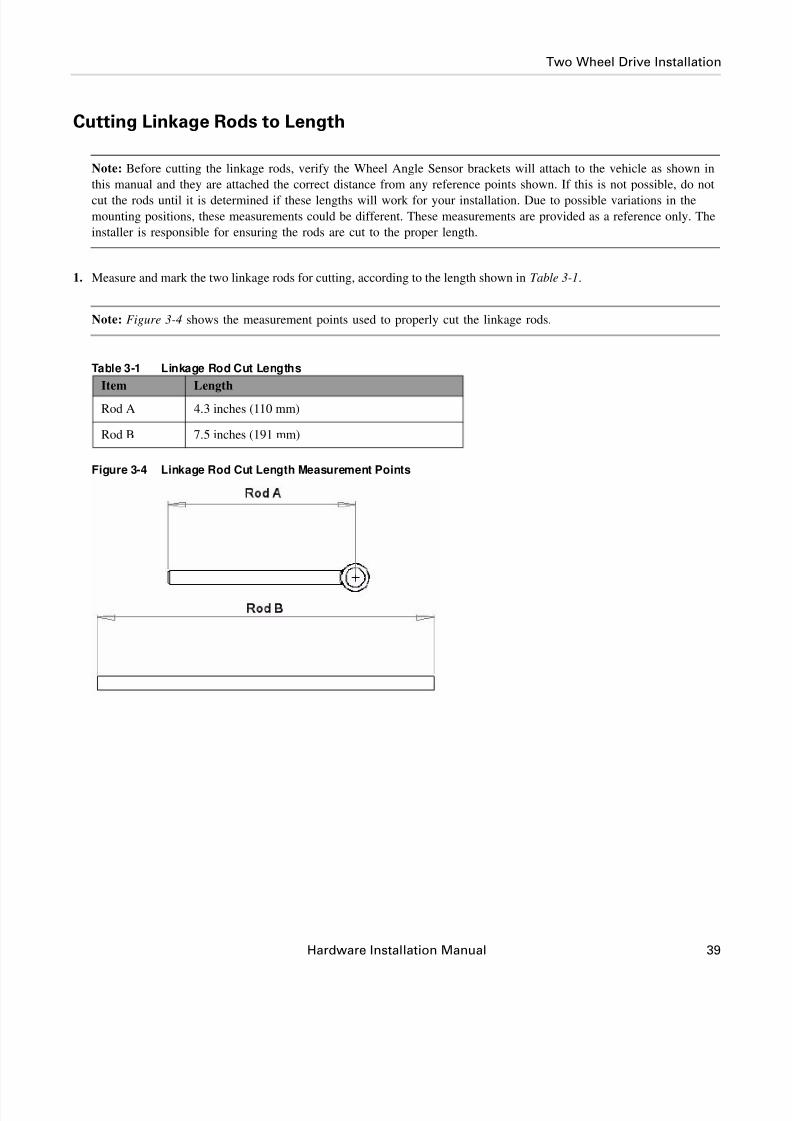
1. Measure and mark the two linkage rods for cutting, according to the length shown in Table 3-1.
Note: Figure 3-4 shows the measurement points used to properly cut the linkage rods.
Table 3-1 Linkage Rod Cut Lengths
Figure 3-4 Linkage Rod Cut Length Measurement Points
Item Length
Rod A 4.3 inches (110 mm)
Rod B 7.5 inches (191 mm)

8/6/2019 4100900-30 - Installation Instructions - CASE 23xx HYD
http://slidepdf.com/reader/full/4100900-30-installation-instructions-case-23xx-hyd 50/116
40 GPS AutoSteer System
Two Wheel Drive Installation
2. Use a hack saw to cut the linkage rod to length while it is held in a bench vise. See Figure 3-5.
Figure 3-5 Linkage Rod Cutting

8/6/2019 4100900-30 - Installation Instructions - CASE 23xx HYD
http://slidepdf.com/reader/full/4100900-30-installation-instructions-case-23xx-hyd 51/116
Hardware Installation Manual 41
Two Wheel Drive Installation
Assembling Linkage Rod Hardware
1. Attach a jam nut to the end of Rod A. See Figure 3-6 .
2. Connect the eye connector to the Wheel Angle Sensor rod end, as shown in Figure 3-6 .
Note: The threaded rods must be cut to the correct lengths before final assembly.
Figure 3-6 Rod A Assembled
3. Attach the jam nuts to each end of linkage Rod B
4. Attach the ball joints to both ends of the linkage arm as shown in Figure 3-7 .
Note: The bolts for the ball joints should be facing the same direction as shown in Figure 3-7 .
Figure 3-7 Linkage Rod Assembled
Eye Connector
Jam Nut

8/6/2019 4100900-30 - Installation Instructions - CASE 23xx HYD
http://slidepdf.com/reader/full/4100900-30-installation-instructions-case-23xx-hyd 52/116
42 GPS AutoSteer System
Two Wheel Drive Installation
Note: The linkage rod after-assembly center-to-center lengths are shown in Table 3-2. Figure 3-8 shows the measurement
points for the assembled linkage rods.
Table 3-2 Assembled Linkage Rod Length
Figure 3-8 Linkage Rod Measurement Points (Assembled)
Item Length
Rod A 5.5" (140mm)
Rod B 9.0" (229mm)
Rod A Measurement
Rod B Measurement

8/6/2019 4100900-30 - Installation Instructions - CASE 23xx HYD
http://slidepdf.com/reader/full/4100900-30-installation-instructions-case-23xx-hyd 53/116
Hardware Installation Manual 43
Two Wheel Drive Installation
Attaching and Adjusting Wheel Angle Sensor Linkage Rods
1. Install the short linkage arm on the Wheel Angle Sensor shaft.
2. Attach the Wheel Angle Sensor linkage rod to the Wheel Angle Sensor. See Figure 3-9.
Note: Leave the Wheel Angle Sensor mounting bolts loose so the sensor can be rotated after installation on the
vehicle.
Figure 3-9 Attaching the Linkage Arm to Sensor (shown on bench)
Wheel Angle Sensor Mounting Bolt
Allen Head Bolt
Washer
Wheel Angle Sensor Mounting Bolt
Nut
8/6/2019 4100900-30 - Installation Instructions - CASE 23xx HYD
http://slidepdf.com/reader/full/4100900-30-installation-instructions-case-23xx-hyd 54/116
44 GPS AutoSteer System
Two Wheel Drive Installation
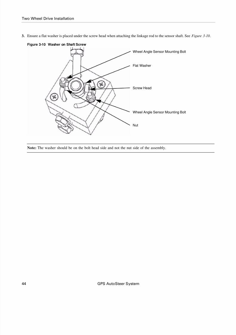
3. Ensure a flat washer is placed under the screw head when attaching the linkage rod to the sensor shaft. See Figure 3-10.
Figure 3-10 Washer on Shaft Screw
Note: The washer should be on the bolt head side and not the nut side of the assembly.
Flat Washer
Screw Head
Nut
Wheel Angle Sensor Mounting Bolt
Wheel Angle Sensor Mounting Bolt

8/6/2019 4100900-30 - Installation Instructions - CASE 23xx HYD
http://slidepdf.com/reader/full/4100900-30-installation-instructions-case-23xx-hyd 55/116
Hardware Installation Manual 45
Two Wheel Drive Installation
Note: Do not turn the steering system or drive the vehicle before the Wheel Angle Sensor has been adjusted using the
AutoSteer Calibration screens. The potentiometer can only rotate a maximum of 180 degrees and if it is rotated
beyond its mechanical stops, it will be permanently damaged.
Note: Do not attach the remaining linkage arm.
4. Install the long threaded linkage on the tie rod bracket using a ball joint. See Figure 3-11.
5. Tighten the ball joint to the bracket with a 1/2" and 9/16" wrench.
Note: Do not attach linkage rod to Wheel Angle Sensor rod at this time.
Figure 3-11 Linkage Rod Connected to Axle Bracket
6. With the linkage rods disconnected, turn the steering wheel so the wheels are centered (the vehicle will travel straight
ahead when moving).
7. Temporarily attach the linkage rods.
Note: Never attach the linkage rods to Wheel Angle Sensor rod and turn the steering system manually or
automatically until the fit has been verified. The linkage rods must remain apart while the steering system is turned to
the maximum right and left positions and then temporarily attached at these positions. Failure to leave the rods
detached may cause the Wheel Angle Sensor or vehicle to become damaged.
Axle Bracket Linkage Rod Attached

8/6/2019 4100900-30 - Installation Instructions - CASE 23xx HYD
http://slidepdf.com/reader/full/4100900-30-installation-instructions-case-23xx-hyd 56/116
46 GPS AutoSteer System
Two Wheel Drive Installation
Note: After the linkage rods are assembled in the following steps, they should move freely without touching any other
parts and without overextending. Make any necessary adjustments to the linkage rods if there is an interference
problem.
8. Rotate the Wheel Angle Sensor potentiometer on top of the mounting block so that the wire connector is parallel to the
Wheel Angle Sensor rod. See Figure 3-12.
Note: The vehicle should be parked in a straight ahead position when adjusting the potentiometer angle.
9. Tighten the potentiometer bolts with a 3/8" wrench and 5/32" Allen wrench.
Figure 3-12 Adjusting Potentiometer Angle
WARNING
Always shut down the vehicle when working around the
steering axle and checking or adjusting the Wheel Angle
Sensor rod lengths. The steering axle could move suddenly
and cause severe injury or death.
Wheel Angle Sensor Connector
Wheel Angle Sensor Rod

8/6/2019 4100900-30 - Installation Instructions - CASE 23xx HYD
http://slidepdf.com/reader/full/4100900-30-installation-instructions-case-23xx-hyd 57/116
Hardware Installation Manual 47
Two Wheel Drive Installation
10. Disconnect the linkage rods and turn the steering wheel manually to the full left position.
11. Reattach the linkage assembly and verify that the sensor will not be damaged. See Figure 3-13,
12. Adjust the rod lengths as necessary.
Figure 3-13 Full Left Wheel Angle Sensor Test
13. Disconnect the linkage rods and turn the steering wheel manually to the full right position.
14. Reattach the linkage assembly and verify the sensor will not be damaged. See Figure 3-14.
15. Adjust the linkage rod lengths as necessary.
Figure 3-14 Full Right Wheel Angle Sensor Test

8/6/2019 4100900-30 - Installation Instructions - CASE 23xx HYD
http://slidepdf.com/reader/full/4100900-30-installation-instructions-case-23xx-hyd 58/116
48 GPS AutoSteer System
Two Wheel Drive Installation
16. Rotate the sensor, adjust the length of either linkage arm and/or reposition the sensor mounting bracket on the vehicle
frame (if necessary) to get the maximum sensor movement.
17. Test the remaining linkage arm for length at hard left and hard right to ensure sensor travel is not exceeded.
Note: The maximum movement is reached when the Wheel Angle Sensor rod sweeps from approximately 3/16 inch
(5mm) from both stop bolts when the steering system is turned to the maximum right and left positions. See
Figure 3-15.
Figure 3-15 Maximum Sensor Movement (as seen from bottom)
Potentiometer Screw Stops
Full Left
Range of Movement
Full Right

8/6/2019 4100900-30 - Installation Instructions - CASE 23xx HYD
http://slidepdf.com/reader/full/4100900-30-installation-instructions-case-23xx-hyd 59/116
8/6/2019 4100900-30 - Installation Instructions - CASE 23xx HYD
http://slidepdf.com/reader/full/4100900-30-installation-instructions-case-23xx-hyd 60/116
50 GPS AutoSteer System
Two Wheel Drive Installation
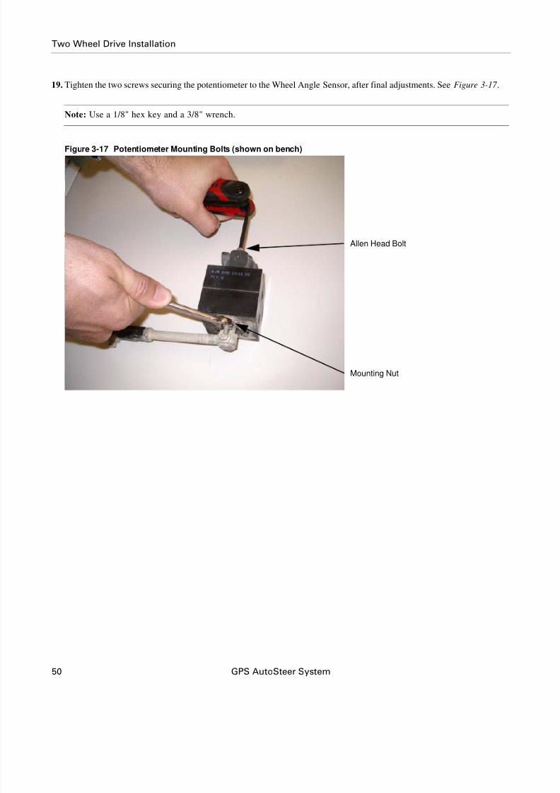
19. Tighten the two screws securing the potentiometer to the Wheel Angle Sensor, after final adjustments. See Figure 3-17 .
Note: Use a 1/8" hex key and a 3/8" wrench.
Figure 3-17 Potentiometer Mounting Bolts (shown on bench)
Allen Head Bolt
Mounting Nut

8/6/2019 4100900-30 - Installation Instructions - CASE 23xx HYD
http://slidepdf.com/reader/full/4100900-30-installation-instructions-case-23xx-hyd 61/116
Hardware Installation Manual 51
Four Wheel Drive Installation
20. The Wheel Angle Sensor installation in now complete. See Figure 3-18.
Figure 3-18 Wheel Angle Sensor Installed
Four Wheel Drive Installation
The Four Wheel Drive AutoSteer Wheel Angle Sensor installation procedure is provided in the following sub-sections:
• Mounting Wheel Angle Sensor Hardware
• Cutting Linkage Rods to Length
• Assembling Linkage Rod Hardware
• Attaching and Adjusting Wheel Angle Sensor Linkage Rods

8/6/2019 4100900-30 - Installation Instructions - CASE 23xx HYD
http://slidepdf.com/reader/full/4100900-30-installation-instructions-case-23xx-hyd 62/116
52 GPS AutoSteer System
Four Wheel Drive Installation
Mounting Wheel Angle Sensor Hardware
1. The Wheel Angle Sensor components are shown in Figure 3-19.
Figure 3-19 Wheel Angle Sensor Components
Linkage Rods
Wheel Angle Sensor
Wheel Angle Sensor Bracket
Wheel Angle Sensor Cable
Wheel Angle Sensor Connector
Linkage Rod Bracket
8/6/2019 4100900-30 - Installation Instructions - CASE 23xx HYD
http://slidepdf.com/reader/full/4100900-30-installation-instructions-case-23xx-hyd 63/116
Hardware Installation Manual 53
Four Wheel Drive Installation
2. Identify the Wheel Angle Sensor mounting location.
Note: The Wheel Angle Sensor is located on the rear steer axle on the left hand side. It is bolted to the outer axle
extension mounting holes See Figure 3-19.
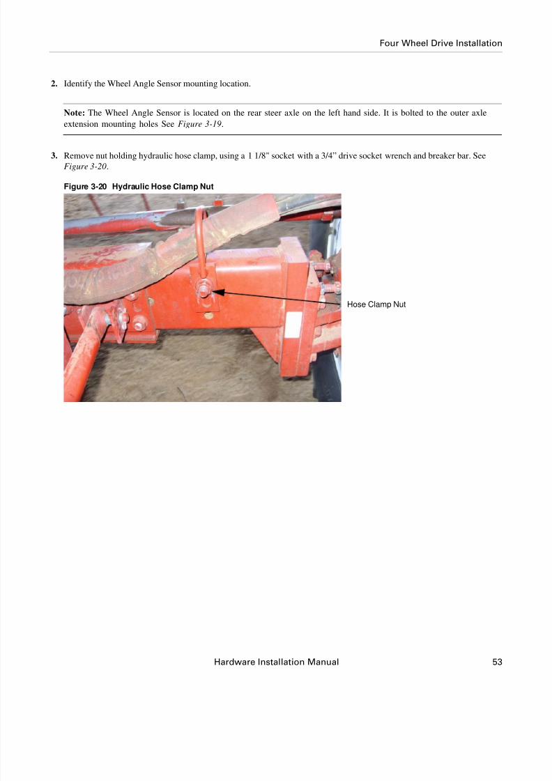
3. Remove nut holding hydraulic hose clamp, using a 1 1/8" socket with a 3/4” drive socket wrench and breaker bar. See
Figure 3-20.
Figure 3-20 Hydraulic Hose Clamp Nut
Hose Clamp Nut

8/6/2019 4100900-30 - Installation Instructions - CASE 23xx HYD
http://slidepdf.com/reader/full/4100900-30-installation-instructions-case-23xx-hyd 64/116
54 GPS AutoSteer System
Four Wheel Drive Installation
4. Place the bracket over the bolt. Use a 5/8 " x 4 ½ " UNC bolt, washer and nut supplied, in bottom hole so that the bracket is
perpendicular to the ground. See Figure 3-21.
Figure 3-21 Mounting Wheel Angle Sensor Bracket
5. Place three large washers over bolt between the WAS bracket and the hose bracket. See Figure 3-22.
Figure 3-22 Placing Washers on Wheel Angle Sensor Bracket

8/6/2019 4100900-30 - Installation Instructions - CASE 23xx HYD
http://slidepdf.com/reader/full/4100900-30-installation-instructions-case-23xx-hyd 65/116
Hardware Installation Manual 55
Four Wheel Drive Installation
6. Fit hose bracket in the best possible position so the hoses will not rub on the WAS bracket.
7. Tighten the bolt using a 1 1/8" socket, 3/4” rachet drive and breaker bar.
8. Tighten bottom bolt using a 15/16 socket, ratchet and wrench. See Figure 3-23.
Figure 3-23 Hose Bracket Reinstalled
9. Attach the Wheel Angle Sensor to the Wheel Angle Sensor bracket. See Figure 3-24.
10. Tighten bolts with a 9/16" wrench.
Figure 3-24 Attaching the Wheel Angle Sensor to the Bracket
Top Mounting Bolt

8/6/2019 4100900-30 - Installation Instructions - CASE 23xx HYD
http://slidepdf.com/reader/full/4100900-30-installation-instructions-case-23xx-hyd 66/116
56 GPS AutoSteer System
Four Wheel Drive Installation
11. Attach the linkage bracket to the drag link by using the 1 1/2" muffler clamp assembly. See Figure 3-25.
12. Position bracket horizontally approximately 1 inch (25mm) from the drag link lock nut.
13. Tighten the nuts using a 1/2" wrench. See Figure 3-25.
Figure 3-25 Attaching Linkage Bracket
Cutting Linkage Rods to Length
Note: Before cutting the linkage rods, verify the Wheel Angle Sensor brackets will attach to the vehicle as shown in
this manual and they are attached the correct distance from any reference points shown. If this is not possible, do not
cut the rods until it is determined if these lengths will work for your installation. Due to possible variations in the
mounting positions, these measurements could be different. These measurements are provided as a reference only. The
installer is responsible for ensuring the rods are cut to the proper length.

8/6/2019 4100900-30 - Installation Instructions - CASE 23xx HYD
http://slidepdf.com/reader/full/4100900-30-installation-instructions-case-23xx-hyd 67/116
Hardware Installation Manual 57
Four Wheel Drive Installation
1. Measure and mark the two linkage rods for cutting, according to the length shown in Figure 3-26 .
Note: Figure 3-26 shows the measurement points used to properly cut the linkage rods.
Table 3-3 Linkage Rod Cut Lengths
Figure 3-26 Linkage Rod Cut Length Measurement Points
Item Length
Rod A 3.7 inches (94 mm)
Rod B 8.3 inches (211 mm)

8/6/2019 4100900-30 - Installation Instructions - CASE 23xx HYD
http://slidepdf.com/reader/full/4100900-30-installation-instructions-case-23xx-hyd 68/116
58 GPS AutoSteer System
Four Wheel Drive Installation
2. Use a hack saw to cut the linkage rod to length while it is held in a bench vise. See Figure 3-27 .
Figure 3-27 Linkage Rod Cutting

8/6/2019 4100900-30 - Installation Instructions - CASE 23xx HYD
http://slidepdf.com/reader/full/4100900-30-installation-instructions-case-23xx-hyd 69/116
Hardware Installation Manual 59
Four Wheel Drive Installation
Assembling Linkage Rod Hardware
1. Attach a jam nut to the end of Rod A. See Figure 3-28.
2. Connect the eye connector to the end of the Wheel Angle Sensor rod. As shown in Figure 3-28.
Note: The threaded rods must be cut to the correct lengths before final assembly.
Figure 3-28 Rod A Assembled
3. Attach the jam nuts to each end of linkage Rod B
4. Attach the ball joints to both ends of the linkage arm as shown in Figure 3-29.
Note: The bolts for the ball joints should be facing the same direction as shown in Figure 3-29.
Figure 3-29 Linkage Rod Assembled
Eye Connector
Jam Nut

8/6/2019 4100900-30 - Installation Instructions - CASE 23xx HYD
http://slidepdf.com/reader/full/4100900-30-installation-instructions-case-23xx-hyd 70/116
60 GPS AutoSteer System
Four Wheel Drive Installation
Note: The linkage rod after-assembly center-to-center lengths are shown in Table 3-2. Figure 3-30 shows the
measurement points for the assembled linkage rods.
Table 3-4 Assembled Linkage Rod Length
Figure 3-30 Linkage Rod Measurement Points (Assembled)
Item Length
Rod A 4.7" (120mm)
Rod B 10.2" (259mm)
Rod A
Measurement
Rod B
Measurement

8/6/2019 4100900-30 - Installation Instructions - CASE 23xx HYD
http://slidepdf.com/reader/full/4100900-30-installation-instructions-case-23xx-hyd 71/116
Hardware Installation Manual 61
Four Wheel Drive Installation
Attaching and Adjusting Wheel Angle Sensor Linkage Rods
1. Install the short linkage arm on the Wheel Angle Sensor shaft.
2. Attach the Wheel Angle Sensor linkage rod to the Wheel Angle Sensor. See Figure 3-31.
Note: Leave the Wheel Angle Sensor mounting bolts loose so the sensor can be rotated after installation on the
vehicle.
Figure 3-31 Attaching the Linkage Arm to Sensor (shown on bench)
Wheel Angle Sensor Mounting Bolt
Allen Head Bolt
Washer
Wheel Angle Sensor Mounting Bolt
Nut

8/6/2019 4100900-30 - Installation Instructions - CASE 23xx HYD
http://slidepdf.com/reader/full/4100900-30-installation-instructions-case-23xx-hyd 72/116
62 GPS AutoSteer System
Four Wheel Drive Installation
3. Ensure a flat washer is placed under the screw head when attaching the linkage rod to the sensor shaft. See Figure 3-32.
Figure 3-32 Washer on Shaft Screw
Note: The washer should be on the bolt head side and not the nut side of the assembly.
Flat Washer
Screw Head
Nut
Wheel Angle Sensor Mounting Bolt
Wheel Angle Sensor Mounting Bolt

8/6/2019 4100900-30 - Installation Instructions - CASE 23xx HYD
http://slidepdf.com/reader/full/4100900-30-installation-instructions-case-23xx-hyd 73/116
Hardware Installation Manual 63
Four Wheel Drive Installation
4. Tighten the connection with a 3/8" wrench and 1/8" Allen wrench. See Figure 3-33.
Note: The rod should point towards the vehicle rear.
Figure 3-33 Tightening Wheel Angle Sensor Linkage Rod Connection
Note: Do not turn the steering system or drive the vehicle before the Wheel Angle Sensor has been adjusted using the
AutoSteer Calibration screens. The potentiometer can only rotate a maximum of 180 degrees and if it is rotated
beyond its mechanical stops, it will be permanently damaged.
8/6/2019 4100900-30 - Installation Instructions - CASE 23xx HYD
http://slidepdf.com/reader/full/4100900-30-installation-instructions-case-23xx-hyd 74/116
64 GPS AutoSteer System
Four Wheel Drive Installation
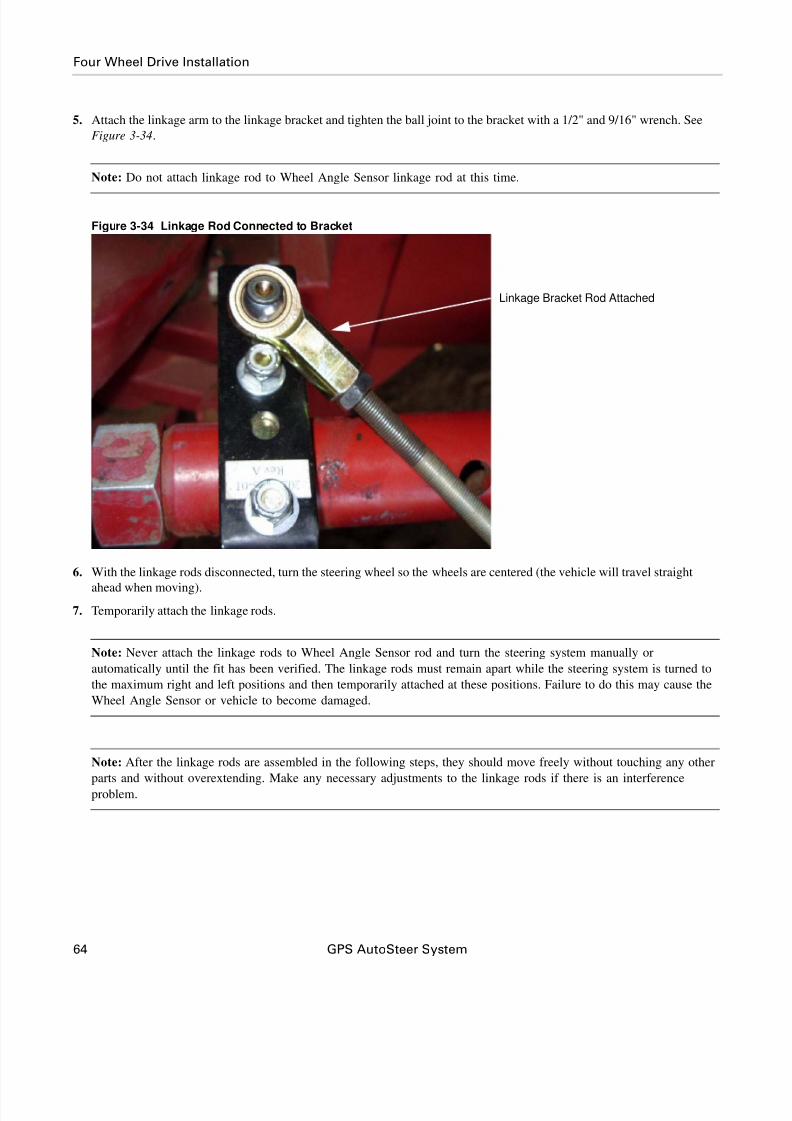
5. Attach the linkage arm to the linkage bracket and tighten the ball joint to the bracket with a 1/2" and 9/16" wrench. See
Figure 3-34.
Note: Do not attach linkage rod to Wheel Angle Sensor linkage rod at this time.
Figure 3-34 Linkage Rod Connected to Bracket
6. With the linkage rods disconnected, turn the steering wheel so the wheels are centered (the vehicle will travel straight
ahead when moving).
7. Temporarily attach the linkage rods.
Note: Never attach the linkage rods to Wheel Angle Sensor rod and turn the steering system manually or
automatically until the fit has been verified. The linkage rods must remain apart while the steering system is turned to
the maximum right and left positions and then temporarily attached at these positions. Failure to do this may cause the
Wheel Angle Sensor or vehicle to become damaged.
Note: After the linkage rods are assembled in the following steps, they should move freely without touching any other
parts and without overextending. Make any necessary adjustments to the linkage rods if there is an interference
problem.
Linkage Bracket Rod Attached

8/6/2019 4100900-30 - Installation Instructions - CASE 23xx HYD
http://slidepdf.com/reader/full/4100900-30-installation-instructions-case-23xx-hyd 75/116
Hardware Installation Manual 65
Four Wheel Drive Installation
8. Rotate the Wheel Angle Sensor potentiometer on top of the mounting block so that the wire connector is parallel to the
Wheel Angle Sensor rod. See Figure 3-35.
Note: The vehicle should be parked in a straight ahead position when adjusting the potentiometer angle.
9. Tighten the potentiometer bolts with a 3/8" wrench and 5/32" Allen wrench.
Figure 3-35 Adjusting Potentiometer Angle
WARNING
Always shut down the vehicle when working around the
steering axle and checking and adjusting the Wheel AngleSensor rod lengths. The steering axle could move suddenly
and cause severe injury or death.
Wheel Angle Sensor Connector
Wheel Angle Sensor Rod
8/6/2019 4100900-30 - Installation Instructions - CASE 23xx HYD
http://slidepdf.com/reader/full/4100900-30-installation-instructions-case-23xx-hyd 76/116
66 GPS AutoSteer System
Four Wheel Drive Installation
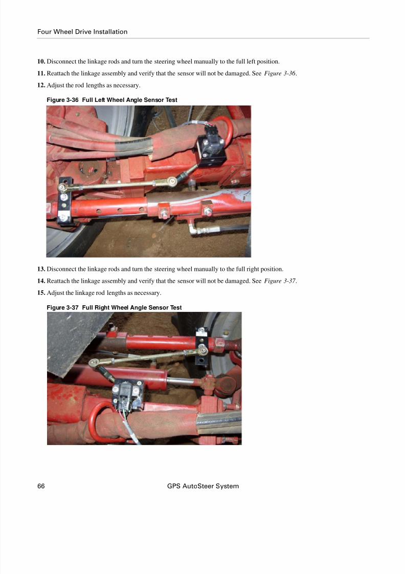
10. Disconnect the linkage rods and turn the steering wheel manually to the full left position.
11. Reattach the linkage assembly and verify that the sensor will not be damaged. See Figure 3-36 .
12. Adjust the rod lengths as necessary.
Figure 3-36 Full Left Wheel Angle Sensor Test
13. Disconnect the linkage rods and turn the steering wheel manually to the full right position.
14. Reattach the linkage assembly and verify that the sensor will not be damaged. See Figure 3-37 .
15. Adjust the linkage rod lengths as necessary.
Figure 3-37 Full Right Wheel Angle Sensor Test

8/6/2019 4100900-30 - Installation Instructions - CASE 23xx HYD
http://slidepdf.com/reader/full/4100900-30-installation-instructions-case-23xx-hyd 77/116
Hardware Installation Manual 67
Four Wheel Drive Installation
16. Rotate the sensor, adjust the length of either linkage arm and/or reposition the sensor mounting bracket on the vehicle
frame (if necessary) to get the maximum sensor movement.
17. Test the remaining linkage arm for length at hard left and hard right to ensure sensor travel is not exceeded.
Note: The maximum movement is reached when the Wheel Angle Sensor rod sweeps from approximately 3/16 inch
(5mm) from both stop bolts when the steering system is turned to the maximum right and left positions. See
Figure 3-38.
Figure 3-38 Maximum Sensor Movement (as seen from bottom)
Potentiometer Screw Stops
Full Left
Range of Movement
Full Right

8/6/2019 4100900-30 - Installation Instructions - CASE 23xx HYD
http://slidepdf.com/reader/full/4100900-30-installation-instructions-case-23xx-hyd 78/116
68 GPS AutoSteer System
Four Wheel Drive Installation
Note: An Ohm meter can also be used to determine if there is enough sensor movement. Connect the Ohm meter to
pins A and B of the Wheel Angle Sensor. Measure the Ohm reading at the maximum left and right position. After
subtracting the smaller number from the larger number, there should be at least a 3.75 kilohms change. The reading
should also never go below 1.6 kilohms or higher than 6.6 kilohms as this is reaching the limits of the potentiometer
and could damage the sensor.
18. When all the adjustments are complete, tighten all linkage rod lock nuts and bolts and the Wheel Angle Sensor rod. See
Figure 3-39.
Note: A 1/2" and two 9/16" wrenches are required to tighten the connections.
Figure 3-39 Linkage Rod Ball Joint Bolt (different vehicle shown)

8/6/2019 4100900-30 - Installation Instructions - CASE 23xx HYD
http://slidepdf.com/reader/full/4100900-30-installation-instructions-case-23xx-hyd 79/116
Hardware Installation Manual 69
Four Wheel Drive Installation
19. Tighten the two screws securing the potentiometer to the Wheel Angle Sensor after final adjustments. See Figure 3-40.
Note: Use a 1/8" hex key and a 3/8" wrench.
Figure 3-40 Potentiometer Mounting Bolts (shown on bench)
Allen Head Bolt
Mounting Nut

8/6/2019 4100900-30 - Installation Instructions - CASE 23xx HYD
http://slidepdf.com/reader/full/4100900-30-installation-instructions-case-23xx-hyd 80/116
70 GPS AutoSteer System
Four Wheel Drive Installation
20. The Wheel Angle Sensor is now installed. See Figure 3-41.
Figure 3-41 Wheel Angle Sensor Installed

8/6/2019 4100900-30 - Installation Instructions - CASE 23xx HYD
http://slidepdf.com/reader/full/4100900-30-installation-instructions-case-23xx-hyd 81/116
Hardware Installation Manual 71
4
SA Module Installation
This SA Module Installation chapter contains information on installing the AutoSteer SA Module.
Installation Procedure
Note: The following instructions provide recommended SA Module mounting instructions. However due to the variety of
options available on vehicles and the possible configuration differences, it may be necessary to install the SA Module inan alternative location. If an alternative location is required, choose a location where the SA Module is protected from
damage from moving parts or crop debris and excessive moisture from weather and cleaning equipment.
1. Locate the space just below the cab front. See Figure 4-1.
Figure 4-1 Mounting Location
SA Module Mounting Location

8/6/2019 4100900-30 - Installation Instructions - CASE 23xx HYD
http://slidepdf.com/reader/full/4100900-30-installation-instructions-case-23xx-hyd 82/116
72 GPS AutoSteer System
Installation Procedure
2. Locate and remove the bolt pointed downward to use for mounting the SA Module Bracket. See Figure 4-2.
Figure 4-2 Existing Bolt to Use For SA Module Bracket Mounting

8/6/2019 4100900-30 - Installation Instructions - CASE 23xx HYD
http://slidepdf.com/reader/full/4100900-30-installation-instructions-case-23xx-hyd 83/116
Hardware Installation Manual 73
Installation Procedure
3. Mount the SA Module to the SA Module bracket using the screws provided and a #2 Phillips screwdriver. See Figure 4-3.
Figure 4-3 Mounting SA Module to Bracket
Mounting Screws
Mounting Screws

8/6/2019 4100900-30 - Installation Instructions - CASE 23xx HYD
http://slidepdf.com/reader/full/4100900-30-installation-instructions-case-23xx-hyd 84/116
74 GPS AutoSteer System
Installation Procedure
4. Mount the SA Module Bracket with SA Module attached as shown using bolt and nut previously removed. See Figure 4-4.
5. Tighten with a rachet and 13mm socket.
Figure 4-4 Mounting SA Module Bracket to Vehicle
6. Figure 4-5 shows the SA Module mounted.
Figure 4-5 SA Module Mounted
SA Module Connector
8/6/2019 4100900-30 - Installation Instructions - CASE 23xx HYD
http://slidepdf.com/reader/full/4100900-30-installation-instructions-case-23xx-hyd 85/116
Hardware Installation Manual 75
5
Roof Module Installation
This Roof Module Installation chapter contains information in the following sections:
• Safety Notes
• Installation Procedure
Safety Notes
• The AutoSteer system must be powered OFF when installing or removing the Roof Module.• The Roof Module must always be firmly secured to the Roof Rail using the hardware whenever the vehicle is in operation
to prevent the Roof Module from releasing from its bracket and falling.
• The Roof Module must be removed when transporting the vehicle at speeds above 30 mph (50 kph).
• Ensure you are in a safe position when attempting to access the cab roof. If necessary for safety, use a ladder to access
the roof. Ensure you do not fall or drop the Roof Module.
WARNING
To prevent injury from falling, ensure you are in a stable
position on the vehicle when installing or removing the Roof
Rail and Roof Module. If the vehicle does not provide a safeplatform, use a ladder to safely access the vehicle roof while
installing or removing the Roof Rail and Roof Module.

8/6/2019 4100900-30 - Installation Instructions - CASE 23xx HYD
http://slidepdf.com/reader/full/4100900-30-installation-instructions-case-23xx-hyd 86/116
76 GPS AutoSteer System
Installation Procedure
Installation Procedure1. Attach the Roof Module brackets to both vehicle mirror mounts using the four U-bolts. See Figure 5-1.
Note: Do not completely tighten the U-bolts until the roof array is mounted and aligned over the brackets.
Figure 5-1 Roof Brackets Mounted on Mirror Mount
Mounting Bolts

8/6/2019 4100900-30 - Installation Instructions - CASE 23xx HYD
http://slidepdf.com/reader/full/4100900-30-installation-instructions-case-23xx-hyd 87/116
Hardware Installation Manual 77
Installation Procedure
2. Attach the Roof Module bracket using bolts, nuts and washers supplied.
3. Tighten securely with a 15/16" socket and ratchet. See Figure 5-2.
Figure 5-2 Attaching the Roof Rail with Bolts
Mounting Bolts and Nuts

8/6/2019 4100900-30 - Installation Instructions - CASE 23xx HYD
http://slidepdf.com/reader/full/4100900-30-installation-instructions-case-23xx-hyd 88/116
78 GPS AutoSteer System
Installation Procedure
4. Attach the three antennas to the correct Roof Module antenna connections. See Figure 5-3.
Note: Hand tighten the connections. Do not use tools or over tighten.
Figure 5-3 Antennas Attached to the Roof Module
WiFi Antenna
RTK Radio Modem Antenna
Cell Modem Antenna

8/6/2019 4100900-30 - Installation Instructions - CASE 23xx HYD
http://slidepdf.com/reader/full/4100900-30-installation-instructions-case-23xx-hyd 89/116
Hardware Installation Manual 79
Installation Procedure
5. Remove the locking pin from the Roof Rail. See Figure 5-4.
Note: Press the Locking Pin release button to enable pin removal.
Figure 5-4 Removing the Quick Release Pin
6. Place the Roof Module on the Roof Rail. See Figure 5-5.
Figure 5-5 Mounting Roof Module on Roof Rail
Pin Release Button

8/6/2019 4100900-30 - Installation Instructions - CASE 23xx HYD
http://slidepdf.com/reader/full/4100900-30-installation-instructions-case-23xx-hyd 90/116
80 GPS AutoSteer System
Installation Procedure
7. Reinsert the locking pin. See Figure 5-6 .
8. Test the tightness of the Roof Module from side-to-side.
Figure 5-6 Reinserting the Locking Pin
9. The Roof Module is now installed. See Figure 5-7 .
Figure 5-7 Roof Module Installed

8/6/2019 4100900-30 - Installation Instructions - CASE 23xx HYD
http://slidepdf.com/reader/full/4100900-30-installation-instructions-case-23xx-hyd 91/116
Hardware Installation Manual 81
6
Display Installation
This Display Installation chapter contains information for installing the Display
1. Locate the welded steel plate located on the cab right side post. See Figure 6-1.
2. Drill an extra 5/16" hole in this position.
Note: Use the steel Display bracket as a template for drilling the hole.
Note: Alternative mounting locations can be used if the location shown is not available.
Figure 6-1 Mounting Holes on Cab Post
AutoSteer Display Mounting Holes
Drilled Mounting Hole
Factory Mounting Hole
Factory Mounting Hole (not used)

8/6/2019 4100900-30 - Installation Instructions - CASE 23xx HYD
http://slidepdf.com/reader/full/4100900-30-installation-instructions-case-23xx-hyd 92/116
82 GPS AutoSteer System
Display Installation
3. Attach the Display bracket to the front corner post using the two kit provided M8 x 25 bolts, nuts and washers. See
Figure 6-2.
4. Tighten the bolts with a 13mm socket and ratchet and 13mm wrench. See Figure 6-2.
Figure 6-2 Display Mounting Bracket Installed
Display Mounting Bracket

8/6/2019 4100900-30 - Installation Instructions - CASE 23xx HYD
http://slidepdf.com/reader/full/4100900-30-installation-instructions-case-23xx-hyd 93/116
Hardware Installation Manual 83
Display Installation
5. Attach the RAM mount to the Display mounting bracket. See Figure 6-3.
6. Secure the Ram base using four 10-32X3/4 Phillip screws and lock nuts.
7. Tighten the screws using a #2 Phillips screw driver and a 3/8 wrench. See Figure 6-3.
Figure 6-3 Attaching the RAM Mount to the Display Bracket
Note: Refer to the Display User Manual for the remaining Display specific installation instructions.

8/6/2019 4100900-30 - Installation Instructions - CASE 23xx HYD
http://slidepdf.com/reader/full/4100900-30-installation-instructions-case-23xx-hyd 94/116
84 GPS AutoSteer System
Display Installation

8/6/2019 4100900-30 - Installation Instructions - CASE 23xx HYD
http://slidepdf.com/reader/full/4100900-30-installation-instructions-case-23xx-hyd 95/116
Hardware Installation Manual 85
7
Connecting System Cables
This Connecting System Cables chapter provides information for connecting the Main Cable Harness and the SA Module
Cable Harness to various vehicle and AutoSteer components in the following sections:
• SA M odule Harness
• SA Module Connection
• AutoSteer Wheel Angle Sensor Connection
• Steering Valve Connection
• Main Cable Harness
• Roof M odule
• Display
• Power Supply Connection
• 12V Cab Power Outlet
• Battery Power Connection
• Install Warning Label
SA Module HarnessThis SA Module Harness section contains the following sub-sections:
• SA Module Connection
• AutoSteer Wheel Angle Sensor Connection

8/6/2019 4100900-30 - Installation Instructions - CASE 23xx HYD
http://slidepdf.com/reader/full/4100900-30-installation-instructions-case-23xx-hyd 96/116
86 GPS AutoSteer System
SA Module Connection
SA Module Connection
1. Locate the previously mounted SA Module. See Figure 7-1.
Figure 7-1 SA Module Harness Cables Bundled with Electrical Tape
2. Align the SA Module Harness connector to the SA Module. See Figure 7-2.
3. Open the connector latch lever. See Figure 7-2.
Figure 7-2 Connecting SA Module Connector (shown on bench)
SA Module Connector
SA Module
SA Module Connector
Locking mechanism in open position (Latch)

8/6/2019 4100900-30 - Installation Instructions - CASE 23xx HYD
http://slidepdf.com/reader/full/4100900-30-installation-instructions-case-23xx-hyd 97/116
Hardware Installation Manual 87
SA Module Connection
4. Press the SA Module Harness connector onto the SA Module connector.
Note: You can damage the connectors if your force them into position. Do not force them together or use tools.
5. Press the latch lever closed until it clicks and locks the connector. See Figure 7-3.
Figure 7-3 Closing the SA Module Connector
Note: If you need to disconnect the SA Module connector, you must open the latch lever before attempting to pull theconnectors apart.
Connector Latch
8/6/2019 4100900-30 - Installation Instructions - CASE 23xx HYD
http://slidepdf.com/reader/full/4100900-30-installation-instructions-case-23xx-hyd 98/116
88 GPS AutoSteer System
AutoSteer Wheel Angle Sensor Connection
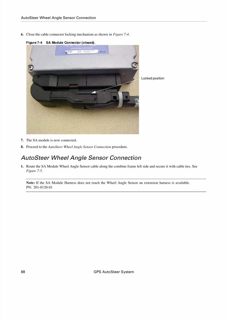
6. Close the cable connector locking mechanism as shown in Figure 7-4.
Figure 7-4 SA Module Connector (closed).
7. The SA module is now connected.
8. Proceed to the AutoSteer Wheel Angle Sensor Connection procedure.
AutoSteer Wheel Angle Sensor Connection
1. Route the SA Module Wheel Angle Sensor cable along the combine frame left side and secure it with cable ties. See
Figure 7-5.
Note: If the SA Module Harness does not reach the Wheel Angle Sensor an extension harness is available.
PN: 201-0120-01
Locked position

8/6/2019 4100900-30 - Installation Instructions - CASE 23xx HYD
http://slidepdf.com/reader/full/4100900-30-installation-instructions-case-23xx-hyd 99/116
8/6/2019 4100900-30 - Installation Instructions - CASE 23xx HYD
http://slidepdf.com/reader/full/4100900-30-installation-instructions-case-23xx-hyd 100/116
90 GPS AutoSteer System
Steering Valve Connection
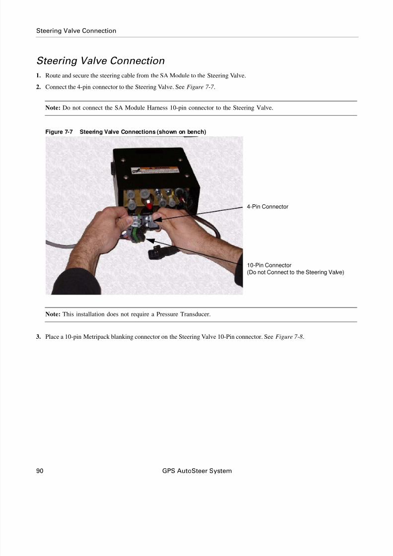
Steering Valve Connection
1. Route and secure the steering cable from the SA Module to the Steering Valve.
2. Connect the 4-pin connector to the Steering Valve. See Figure 7-7 .
Note: Do not connect the SA Module Harness 10-pin connector to the Steering Valve.
Figure 7-7 Steering Valve Connections (shown on bench)
Note: This installation does not require a Pressure Transducer.
3. Place a 10-pin Metripack blanking connector on the Steering Valve 10-Pin connector. See Figure 7-8.
4-Pin Connector
10-Pin Connector
(Do not Connect to the Steering Valve)

8/6/2019 4100900-30 - Installation Instructions - CASE 23xx HYD
http://slidepdf.com/reader/full/4100900-30-installation-instructions-case-23xx-hyd 101/116
Hardware Installation Manual 91
Steering Valve Connection
Figure 7-8 10-Pin SA Module Harness Terminator
4. Connect the Flow Switch adapter harness to the SA Module Harness 10-pin connector. See Figure 7-9.
Figure 7-9 Connecting the Flow Switch Adapter Harness
5. Connect the opposite end of Flow Switch adapter harness to the vehicle Flow Switch connector.
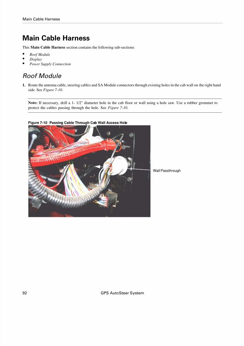
8/6/2019 4100900-30 - Installation Instructions - CASE 23xx HYD
http://slidepdf.com/reader/full/4100900-30-installation-instructions-case-23xx-hyd 102/116
92 GPS AutoSteer System
Main Cable Harness
Main Cable HarnessThis Main Cable Harness section contains the following sub-sections:
• Roof M odule
• Display • Power Supply Connection
Roof Module
1. Route the antenna cable, steering cables and SA Module connectors through existing holes in the cab wall on the right hand
side. See Figure 7-10.
Note: If necessary, drill a 1- 1/2" diameter hole in the cab floor or wall using a hole saw. Use a rubber grommet to
protect the cables passing through the hole. See Figure 7-10.
Figure 7-10 Passing Cable Through Cab Wall Access Hole
Wall Passthrough

8/6/2019 4100900-30 - Installation Instructions - CASE 23xx HYD
http://slidepdf.com/reader/full/4100900-30-installation-instructions-case-23xx-hyd 103/116
Hardware Installation Manual 93
Roof Module
2. Connect the 12-pin data and 2-pin power connectors between the Main Cable Harness and the SA Module Harness. See
Figure 7-11.
Figure 7-11 Main Cable Harness to SA Module Harness Connections (shown on bench)
3. Route the Main Cable Harness up the cab side. See Figure 7-12.
Figure 7-12 Route Main Harness Up Cab Right Side
12-Pin Connectors
2-Pin Connector
Main Harness To Roof Module

8/6/2019 4100900-30 - Installation Instructions - CASE 23xx HYD
http://slidepdf.com/reader/full/4100900-30-installation-instructions-case-23xx-hyd 104/116
94 GPS AutoSteer System
Roof Module
4. Connect the Main cable Harness to the Roof Module connector. See Figure 7-13.
5. Orient the 12-pin connector so the word TOP on the cable connector is pointing upwards (towards the sky). See
Figure 7-13.
6. Insert the cable connector into the Roof Module. Push the connector in until it clicks and locks in place.
Note: To remove the connector, grasp the connector to compress the two side latches and then pull away from the
Roof Module.
Figure 7-13 Connecting the Main Harness to Roof Module
7. Orient the Ethernet cable connector with the connector under the receiver so the contacts on the cable connector are
pointing towards the back of the vehicle. See Figure 7-14.
Note: This orientation is usually towards your right side if you are standing on the vehicle left side and looking towards
the Roof Module.
8. Slide the cable connector into the receiver and rotate the plastic bayonet sleeve clockwise to lock the connector. See
Figure 7-14.
Main Harness Connection

8/6/2019 4100900-30 - Installation Instructions - CASE 23xx HYD
http://slidepdf.com/reader/full/4100900-30-installation-instructions-case-23xx-hyd 105/116
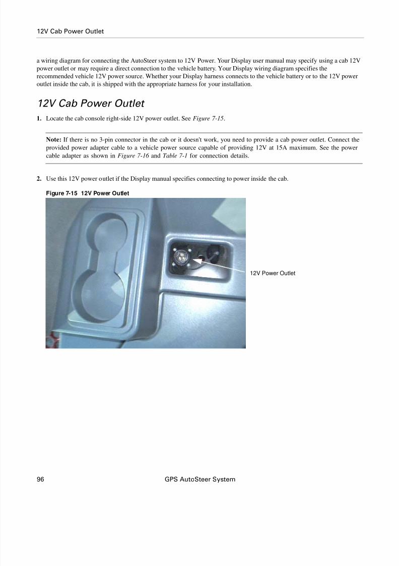
8/6/2019 4100900-30 - Installation Instructions - CASE 23xx HYD
http://slidepdf.com/reader/full/4100900-30-installation-instructions-case-23xx-hyd 106/116
96 GPS AutoSteer System
12V Cab Power Outlet
a wiring diagram for connecting the AutoSteer system to 12V Power. Your Display user manual may specify using a cab 12V
power outlet or may require a direct connection to the vehicle battery. Your Display wiring diagram specifies the
recommended vehicle 12V power source. Whether your Display harness connects to the vehicle battery or to the 12V power
outlet inside the cab, it is shipped with the appropriate harness for your installation.
12V Cab Power Outlet
1. Locate the cab console right-side 12V power outlet. See Figure 7-15.
Note: If there is no 3-pin connector in the cab or it doesn't work, you need to provide a cab power outlet. Connect the
provided power adapter cable to a vehicle power source capable of providing 12V at 15A maximum. See the power
cable adapter as shown in Figure 7-16 and Table 7-1 for connection details.
2. Use this 12V power outlet if the Display manual specifies connecting to power inside the cab.
Figure 7-15 12V Power Outlet
12V Power Outlet

8/6/2019 4100900-30 - Installation Instructions - CASE 23xx HYD
http://slidepdf.com/reader/full/4100900-30-installation-instructions-case-23xx-hyd 107/116
Hardware Installation Manual 97
12V Cab Power Outlet
3. Connect the Red (+) and Black (-) power cable adapter wires to 12 volt power on the vehicle protected by a 15 amp fuse.
Note: Table 7-1 shows the Power Cable Adapter pinout.
Figure 7-16 Power Cable Adapter (201-0156-01)
Table 7-1 Power Adapter Cable Pinout
Wire Color Function
Red 12 V Unswitched Power
White 12V Switched Power
Black Ground
3-Pin 12V Power Connector
Vehicle Connection
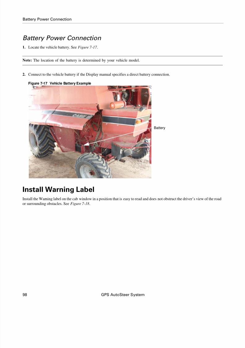
8/6/2019 4100900-30 - Installation Instructions - CASE 23xx HYD
http://slidepdf.com/reader/full/4100900-30-installation-instructions-case-23xx-hyd 108/116
98 GPS AutoSteer System
Battery Power Connection
Battery Power Connection
1. Locate the vehicle battery. See Figure 7-17 .
Note: The location of the battery is determined by your vehicle model.
2. Connect to the vehicle battery if the Display manual specifies a direct battery connection.
Figure 7-17 Vehicle Battery Example
Install Warning LabelInstall the Warning label on the cab window in a position that is easy to read and does not obstruct the driver’s view of the road
or surrounding obstacles. See Figure 7-18.
Battery
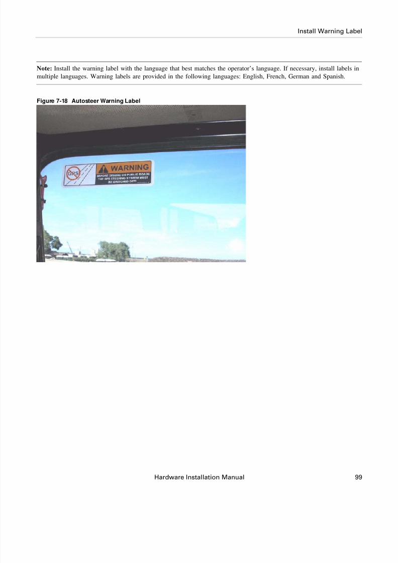
8/6/2019 4100900-30 - Installation Instructions - CASE 23xx HYD
http://slidepdf.com/reader/full/4100900-30-installation-instructions-case-23xx-hyd 109/116
Hardware Installation Manual 99
Install Warning Label
Note: Install the warning label with the language that best matches the operator’s language. If necessary, install labels in
multiple languages. Warning labels are provided in the following languages: English, French, German and Spanish.
Figure 7-18 Autosteer Warning Label

8/6/2019 4100900-30 - Installation Instructions - CASE 23xx HYD
http://slidepdf.com/reader/full/4100900-30-installation-instructions-case-23xx-hyd 110/116
100 GPS AutoSteer System
Install Warning Label

8/6/2019 4100900-30 - Installation Instructions - CASE 23xx HYD
http://slidepdf.com/reader/full/4100900-30-installation-instructions-case-23xx-hyd 111/116
Hardware Installation Manual 101
8
Post-Installation Procedures andInformation
This Post-Installation Procedures and Information chapter contains information on procedures and processes that should be
completed after the installation process is complete. The information for this chapter is contained in the following sections:
• Verify the Vehicle is Ready for AutoSteer
• Calibration and Tuning Notes
• Adjusting the AutoSteer Relief Valve
Verify the Vehicle is Ready for AutoSteer1. Ensure all connectors are properly coupled.
2. Power ON the AutoSteer system.
3. Verify installation and system operation.
Calibration and Tuning Notes
Note: For optimal steering performance, the AutoSteer system must be fully calibrated and then tuned.
Select the appropriate Case Combine model when setting up your vehicle on the AutoSteer system Display.

8/6/2019 4100900-30 - Installation Instructions - CASE 23xx HYD
http://slidepdf.com/reader/full/4100900-30-installation-instructions-case-23xx-hyd 112/116
102 GPS AutoSteer System
Adjusting the AutoSteer Relief Valve
Adjusting the AutoSteer Relief ValveThe AutoSteer steering valve has a built-in Load Sense Relief Valve that limits the maximum pump pressure when
AutoSteering. The Relief Valve must be adjusted after you have completed the hydraulic installation and before you turn on
AutoSteer.
Figure 8-1 AutoSteer Relief Valve Adjustment
Note: The Relief Valve in Figure 8-1 is shown on a bench without the hydraulic hoses connected for ease of viewing the
adjustment process. When you adjust the Relief Valve, it is done with the valve mounted on the vehicle and the hydraulichoses connected.
Follow the procedure below to adjust the Relief Valve:

8/6/2019 4100900-30 - Installation Instructions - CASE 23xx HYD
http://slidepdf.com/reader/full/4100900-30-installation-instructions-case-23xx-hyd 113/116
Hardware Installation Manual 103
Adjusting the AutoSteer Relief Valve
1. Install a 5000 psi pressure gauge on the AutoSteer valve diagnostics coupler labeled as GP. Use a short extension hose on
the pressure gauge if necessary for easier reading. See Figure 8-2.
Figure 8-2 Pressure Gauge
2. Put transmission into “neutral” or “park” position and turn on the hand brake.
3. Start the engine and leave it at low idle.
4. Immediately check for oil leaks on all hose connections that were opened.
5. Turn the steering wheel full right and then full left and check for correct manuals steering response. Immediately check for
oil leaks on all hose connections that were opened. Air in the hoses may cause a slight steering delay when the system is
first powered up.
6. Observe the standby pump pressure shown on your pressure gauge. Standby pressure should be very low, or around 350
psi. If standby pump pressure is zero or less than 100 psi, you might have inverted the Pressure and Tank hoses.
7. Clear any bystanders from around the vehicle because you will be moving the front wheels in the next step.
8. With the display turned ON access the Hydraulic Valve window from the Steering Components Window and command
the steering full Right and full Left. The front wheels will turn towards each of the directional stops. The maximum pump
pressure will be indicated on the pressure gauge when the wheels hit the stops.
9. Adjust the AutoSteer relief valve so that the maximum pump pressure is 2400 psi when the wheels hit the stops.
10. Tighten the jam nut on the relief valve once the correct pressure setting has been adjusted.
11. Remove your pressure gauge by sliding the sleeve on the quick coupler.

8/6/2019 4100900-30 - Installation Instructions - CASE 23xx HYD
http://slidepdf.com/reader/full/4100900-30-installation-instructions-case-23xx-hyd 114/116
104 GPS AutoSteer System
Adjusting the AutoSteer Relief Valve

8/6/2019 4100900-30 - Installation Instructions - CASE 23xx HYD
http://slidepdf.com/reader/full/4100900-30-installation-instructions-case-23xx-hyd 115/116
Hardware Installation Manual 105
9
Final Hardware Installation Checklist
This Final Checklist chapter contains the verifications steps necessary after the installation of the AutoSteer system.
Note: The Final Hardware Installation Checklist is on the back of this page. You should keep a copy of this checklist and
this manual for future reference when servicing the vehicle.
Vehicle Model: _________________________________ Year: _________ Serial #: _________________________
Customer Name: _______________________________________________________________________________
Location/Address: ______________________________________________________________________________
AutoSteer Installation Kit Part Number: ______________________________________________________________
NOTES
____________________________________________________________________________________________________
____________________________________________________________________________________________________
____________________________________________________________________________________________________
____________________________________________________________________________________________________
____________________________________________________________________________________________________
____________________________________________________________________________________________________
Name of Installer: __________________________________________ Date: ________________

8/6/2019 4100900-30 - Installation Instructions - CASE 23xx HYD
http://slidepdf.com/reader/full/4100900-30-installation-instructions-case-23xx-hyd 116/116
Final Hardware Installation Checklist
System Installation Checklist
Hydraulic Installation Checklist
AutoSteer Performance Checklist
1. Wheel Angle Sensor Installed and all fasteners are tight.
2. Monitor Bracket Installed and all fasteners are tight.
3. Roof Rail is installed and all fasteners are tight.
4. SA Module is installed and all fasteners are tight.
5. All cable ends are connected.
6. All cables are secured with cable ties.
7. Roof Module locking pin is installed.
1. Valve bracket is installed and all fasteners are tight.
2. Valve is installed and all fasteners are tight.
3. All hose fittings are tight.
4. Check the Priority Valve for proper installation and hose connection.
5. Check for oil leaks on all hydraulic connections.
6. All hoses are routed and secured with cable ties.
7. Adjust the AutoSteer Relief Valve.
8. Measure the standby pump pressure. Value_______________
9. Measure the maximum pump pressure in AutoSteer mode. Value_______________
10. Manual steering is normal after the AutoSteer installation.
1. Complete AutoSteer system calibration.
2. Complete AutoSteer system tuning.