€¦ · 4 symptom page number section four - drive system diagnostics drive system is not...
TRANSCRIPT

P.O. Box 1160St. Joseph, MO 64502-1160
Phone: (816) 364-0317Fax: (816) 390-9379
www.snorkelusa.comP/N 074446Sept. 1998
������������
�����
������������������� �
������������������� �


1
GENERAL INFORMATIONThis manual contains procedures for locating and correcting the majority of problems which may
develop on the “Snorkelift” TB 42/50 Aerial Platform built after June 1997.
Since the majority of malfunctions experienced on equipment in the aerial platform Industry areassociated with the hydraulic and electrical systems, great effort has been made to develop a guidewhich insures that procedures regarding these areas are given the fullest possible attention and detail.As a result of these efforts, the aerial platform has been divided into twelve distinct groups with eachgroup covered by an individual section. The Sections are as follows:
1.) Engine Diagnostics 7.) Platform Rotation System Diagnostics2.) Hydraulic Pump Diagnostics 8.) Platform Leveling System Diagnostics3.) Steering System Diagnostics 9.) Boom Elevation System Diagnostics4.) Drive System Diagnostics 10.) Telescope System Diagnostics5.) Emergency Power System Diagnostics 11.) Fuel System Diagnostics6.) Swing System Diagnostics 12.) Accessories Diagnostics
NOTES, CAUTIONS AND DANGERSThe terms NOTE, CAUTION, and DANGER appear throughout this manual and have specific mean-ings.
A NOTE provides additional or special information to make a step or procedure easier orclearer. Disregarding a NOTE might cause inconvenience, but would not cause equipment damage orpersonal injury.
A is provided in a procedure wherever minor personal injury or equipmentdamage could result. Disregarding a CAUTION could cause damage to the machine; however seriouspersonal injury is unlikely.
is the most serious and emphasizes areas where personnel injury and evendeath could result from negligence. Permanent mechanical damage is also highly probable. DANGERsigns are to be taken seriously. In some cases, serious injury or death has resulted from disregarding
a DANGER.
NOTE: Engine maintenance and troubleshooting information not contained in this manual may be
found in the engine maintenance manual originally provided with the machine, or from the EngineManufacture/Dealer Network.
It should be recognized that every person who performs testing and diagnostic procedures and everyperson supervising any of these functions must be properly trained and qualified. If a problem shouldoccur which is not covered by this manual or which cannot be corrected using the listed correctiveactions, technically qualified guidance from the Service Department of Snorkel International Inc.,should be obtained prior to proceeding further. Tel: (816) 364-0317
NOTE: Diagnostic procedures basically consist of a logical process of elimination. For this reason,it is very important that the steps be performed in the order in which they are presented. Always beginby localizing the problem and defining the symptoms as accurately as possible. When the problem hasbeen localized, make sure to completely read and comprehend the appropriate flow chart. Do notattempt to make shortcuts.

2
MANUAL DESIGN
Each symptom described is followed by a list of inspections to be performed. Each inspection is in theform of a flowchart. A set of detailed checks are then performed at the component and/or relatedareas which confirm or decline the outcome. If the inspection is declined the flowchart will refer to thenext step to be performed until the problem is confirmed. The diagnosis then enables a determination.
Problem Go to PageInspect
Go to PageInspect
OK
Step 1
Step 2
Example: Problem Solving Procedure
Inspect
Troubleshoot(Identify Problem)
Replace orperform repair
If
Go to step
no
Yes
Example: Flowchart Procedure
EQUIPMENT NEEDED:Multimeter: A meter designed to read voltage, amperage and resistance.
Pressure Test Gauge: A pressure gauge rated for 0 - 1000 psi.
A pressure gauge rated for 0 - 5000 psi.
Tachometer: A meter designed to measure engine RPM on gas and/or diesel.
(Photo Tachometer is recommended)
Flowmeter: A meter designed to measure fluid flow.
Stopwatch: A tool designed to measure time.

3
SYMPTOM PAGE NUMBER
Section One - Engine DiagnosticsEngine starter fails to operate (No Electrical) 9
Starter disengages before engine starts 10
Engine cranks over but will not start 10
Engine starts then shuts down after 30 seconds 11
Engine will not accelerate 11
Engine over accelerates 12
Engine will not start from platform control 12
Engine starts while cranking, then dies when key switch is released 13
Section Two - Hydraulic DiagnosticsHydraulic system functions on emergency power only 39
Hydraulic pump stays on stroke 39
Hydraulic oil overheats while idling 39
Hydraulic oil overheats during operation 40
Hydraulic functions are sluggish 40
Hydraulic pump will not build pressure 40
Hydraulic pump will not build enough pressure 41
Flow from hydraulic pump is too low 41
Flow from hydraulic pump is too high (kills engine) 41
Section Three - Steering System DiagnosticsMachine will not steer 55

4
SYMPTOM PAGE NUMBER
Section Four - Drive System DiagnosticsDrive system is not operational with controller in either direction 63
No forward drive (Reverse OK) 64
No reverse drive (Forward Ok) 64
Drive high range not operating 65
Machine drives at full speed with platform raised and/or extended 65
Brakes will not release 65
Only one wheel turns (2 wheel drive) 66
One wheel turns faster than other (2 wheel drive) 66
Section Five - Emergency Power System DiagnosticsEmergency pump motor non-operational 87
No functions when on emergency power 87
Section Six - Swing System DiagnosticsSwings only in one direction 95
No response from swing when platform controls are activated 95
No response from swing when ground controls are activated 96
Swings erratically in either direction 96
Swings faster one way than other 96
Swing brake will not hold 97
Swings too slow 97
Section Seven - Platform Rotation System DiagnosticsPlatform rotate does not operate 113
Platform rotates too fast 113
Platform rotates too slow 113
Platform rotates itself 113

5
SYMPTOM PAGE NUMBER
Section Eight - Platform Leveling System DiagnosticsPlatform will not maintain level as boom raises or lowers 121
Platform will not maintain level with machine off 121
Platform bleeds down 121
Platform level will not work from ground control 121
Platform level will not work from platform control 122
Platform level up function is inoperative 122
Platform level down function is inoperative 122
Section Nine - Boom Elevation System DiagnosticsBoom raises but will not stay elevated 135
Boom will not raise from platform control 135
Boom will not raise from ground control 135
Boom raises slow from platform 135
Section Ten - Telescope System DiagnosticsBoom will not retract from ground control (Platform Control Ok) 143
Boom will not retract from platform control (Ground Control Ok) 143
Boom will not extend from ground control (Platform Control Ok) 143
Boom will not extend from platform control (Ground Control Ok) 144
Boom drifts in 144
Section Eleven - Fuel System DiagnosticsEngine will not start on gasoline, but will start on L.P. 157
Engine will not start on L.P., but will start on gasoline 157

6
SYMPTOM PAGE NUMBER
Section Twelve - Accessories DiagnosticsAC Generator will not function 165
AC Generator has low voltage 165
Machine will not steer 165

SECTION ONE:ENGINE DIAGNOSTICS


SECTION ONEENGINE DIAGNOSTICS
Troubleshooting Guide Flowchart 9 TB 42/50
InspectStarter Solenoid
InspectPower Cables and
Battery Disconnect Switch
InspectGround Contro l
Circui t Breaker (25 Amp)
InspectEmergency Stop Swi tch
InspectGround Master (Key) Swi tch
InspectEngine Starter Relay
InspectIgni t ion/Emergency
Power Swi tch
InspectGround/Plat formSelector Switch
InspectEngine Ant i -Restart Relay
Engine starterfails to operate(No Electrical)
Go to Page14
InspectBat tery and Cable Connect ions
Go to Page14
Go to Page15
Go to Page16
Go to Page16
Go to Page17
Go to Page17
Go to Page18
Go to Page18
Go to Page19
OK
OK
OK
OK
OK
OK
OK
OK
OK
Chart 1
Step 1
Step 2
Step 4
Step 5
Step 6
Step 7
Step 8
Step 9
Step 10
Step 11
InspectAmmete r
Go to Page15
OKStep 3

SECTION ONEENGINE DIAGNOSTICS
Troubleshooting Guide Flowchart 10 TB 42/50
Starterdisengages before
engine starts
Go to Page20
InspectEngine Ant i -Restart Relay
Engine cranksover but
will not start
Go to Page21
InspectGround Master (Key) Swi tch
Go to Page21
InspectGround/Plat form Selector Switch
Go to Page22
InspectIgni t ion/Emergency Power Swi tch
Go to Page22
InspectRun Relay
Go to Page23
InspectMurphy (Magnet ic) Swi tch
(Ford only)
Go to Page23
InspectMurphy (Magnet ic) Swi tch
(Deutz only)
OK
OK
OK
OK
Chart 2
Chart 3
Step 1
Step 2
Step 3
Step 4
Step 5
Step 6
Step 1
Go to Page20
InspectStarter Solenoid
OKStep 2
Go to Page24
InspectRun Solenoid(Deutz only)
OKStep 7
OK

SECTION ONEENGINE DIAGNOSTICS
Troubleshooting Guide Flowchart 11 TB 42/50
Engine startsthen shuts downafter 30 seconds
Go to Page25
InspectEngine Temperature Gauge
Go to Page25
InspectEngine Oi l Pressure Switch
Engine will notaccelerate
Go to Page26
InspectThrott le Circui t Breaker (15 Amp)
Go to Page26
InspectMedium Throt t le Relay
(Ford only)
Go to Page27
InspectHigh Thrott le Relay
(Ford only)
Go to Page27
InspectThrott le Governor or Control ler
(Ford only)
Go to Page28
InspectActuator
(Ford only)
OK
OK
OK
OK
OK
Chart 4
Chart 5
Step 1
Step 2
Step 1
Step 2
Step 3
Step 4
Step 5
Go to Page28
InspectThrott le Relay(Deutz only)
Go to Page29
InspectThrott le Solenoid
(Deutz only)
OK
Step 6
Step 7
OK

SECTION ONEENGINE DIAGNOSTICS
Troubleshooting Guide Flowchart 12 TB 42/50
Chart 6
Engine overaccelerates
Go to Page30
Inspect Governor(Ford only)
Go to Page30
InspectActuator
(Ford only)
OK
Step 1
Step 2
Engine will notstart from
platform control
Go to Page31
InspectPlat form Control
Circui t Breaker (20 Amp)
Go to Page32
InspectEmergency Stop Swi tch
Go to Page32
InspectFoot Swi tch
Go to Page32
InspectPlat form Start Switch
OK
OK
OK
Chart 7
Go to Page31
InspectGround/Plat form Selector Switch
OK
Go to Page33
InspectIgni t ion/Emergency Power Swi tch
OK
Step 1
Step 2
Step 3
Step 4
Step 5
Step 6

SECTION ONEENGINE DIAGNOSTICS
Troubleshooting Guide Flowchart 13 TB 42/50
Engine starts whilecranking, then dieswhen key switch is
released
Go to Page34
InspectRun Solenoid
Step 1
Chart 8
Go to Page34
InspectRun Relay
OKStep 2
Go to Page35
InspectVacuum Swi tch
(Ford only)
OKStep 2

SECTION ONEENGINE DIAGNOSTICS
Troubleshooting Guide Flowchart 14 TB 42/50
Engine starterfails to operate(No Electrical)
InspectPower Cables andBattery Disconnect
Switch
Using a meter set toread voltage, measure
voltage enteringBattery Disconnect SwitchShould read 12-12.7 volts
Battery DisconnectSwitch in Off
Posit ion
If 12-12.7V
Using a meter set toread voltage, turn
Battery Disconnect Switchto On posit ion, measure
voltage coming out ofBattery Disconnect SwitchShould read 12-12.7 voltsReset Battery
Disconnect Switchto On Posit ion
If
Repair or replaceBattery Disconnect Switch
and/orBattery Disconnect Switch
wiring
If low or no reading
Go to step 3
If12-12.7V
Then
InspectBatteries
Using a meterset to read
voltage, checkeach battery for
12 volts whileunder load
Recharge orreplace
battery(s)
Check batteryconnect ions
If loose
If low or no voltage
Clean allconnect ions
Tighten allconnect ions
Ifcorroded
If 12V
Step 1
Step 2
Batteries omit hydrogenand oxygen elements thatcan combine explosively.Do not smoke or permitopen f lames or sparkswhen checking batteries

SECTION ONEENGINE DIAGNOSTICS
Troubleshooting Guide Flowchart 15 TB 42/50
Using a meter set to readvoltage, turn BatteryDisconnect Switch to
On posit ion,measure voltage enteringEmergency Stop SwitchShould read 10-12 volts
Step 3
Step 4Inspect
Ground ControlCircuit Breaker
(25 Amp)
Circuit breaker isopen
If low or no reading
Check for voltage betweenCircuit Breaker and
Emergency Stop Switchon wire #1A
Should read 12 volts
Reset Circuitbreaker
Then
If
Repair or replaceCircuit Breaker
and/orCircuit Breaker wiring
If low or no reading
Go to step 5
If10-12V
InspectAmmeter
Using a meter set to readvoltage, measure voltage
between1. Battery Disconnect
Switch and Ammeter (+)on wire # 57
2.Ammeter (-) and CircuitBreaker on wire #1A
Should read 12-12.7 volts
If low or no reading
Repair or replaceCircuit Breaker
and/orCircuit Breaker wiring
Go to step 4
If12-12.7V

SECTION ONEENGINE DIAGNOSTICS
Troubleshooting Guide Flowchart 16 TB 42/50
Step 5
Step 6Inspect
Ground Master(Key) Switch
Using a meter set to readvoltage, activate engine
starter and measurevoltage between Battery
post side of GroundMaster Switch and start
side of GroundMaster Switch.
Should read 12 voltsGo to step 7
Repair or replaceGround Master Switch
and/orGround Master Switch
wiring
If12V
If low or no reading
InspectEmergency Stop
Switch
Using a meterset to read voltage, pullEmergency Stop Switch
out and measurevoltage between
Emergency Stop Switchand Battery side of
Ground Master(Key) Switch.
Should read 10-12 volts
Emergency StopSwitch is off(pushed in)
If low or no readingPul l Emergency
Stop Switch (out)to the On posit ion
If
ReplaceEmergency Stop Switch
and/orEmergency Stop Switch
wiringGo to step 6
If10-12V
Then

SECTION ONEENGINE DIAGNOSTICS
Troubleshooting Guide Flowchart 17 TB 42/50
Step 7
Step 8Inspect
Ground/PlatformSelector Switch
Set Selector Switch toGround posit ion. Using ameter set to read voltage,
activate starter andmeasure voltage betweenIgnit ion/Emergency Power
Switch and Ground/Platform Selector SwitchShould read 10-12 volts
Ground/PlatformSelector Switch isin Platform posit ion
Return Ground/Platform SelectorSwitch to Ground
posit ion
Then
If
Go to step 9
If low or no reading
ReplaceGround/Platform Selector
Switch and/orGround/Platform Selector
Switch wiring
If10-12V
InspectIgnit ion/Emergency
Power Switch
Using a meter set toread voltage, activate
engine starter andmeasure vol tage
betweenGround Master Switch andIgnit ion/Emergency Power
SwitchShould read 10-12 volts
Go to step 8 If10-12V
If low or no reading
ReplaceIgnit ion/Emergency Power
Switch and/orIgnit ion/Emergency Power
Switch wiring

SECTION ONEENGINE DIAGNOSTICS
Troubleshooting Guide Flowchart 18 TB 42/50
Step 9
Step 10Inspect
Engine StarterRelay
Using a meter set toread voltage, activate
engine starter and measurevoltage from
1. wire #5B to StarterRelay.
2. wire from StarterRelay to Ground
Should read 10-12 voltsCheck ground
continuityIf
10-12V
If low or no reading
ReplaceEngine Starter
Relay
No cont inui ty
ReplaceEngine Starter Relay wiring
Go to step 11
Continuity
Go to step 10
InspectEngine Anti-
Restart Relay
Using a meter set toread voltage, activate
engine starter andmeasure vol tage
between Ground ControlSwitch and Anti-Restart
Relay on wire #5C.Should read 10-12 volts
Measure voltage atwire #5B.
Should read 10-12 volts
ReplaceEngine Anti-
Restart Relay
If low or no reading
Replacewiring to
Engine AntiRestart Relay
Check Adjustable Resistorbetween Terminal
164 and 164B,Adjust asneeded for starter to
engage.
If 10-12v
If lowor no
reading
If10-12v
If stilldoesnot
engage

SECTION ONEENGINE DIAGNOSTICS
Troubleshooting Guide Flowchart 19 TB 42/50
Step 11
InspectStarter Solenoid
Using a meter set toread voltage, activate
engine starter and measurevoltage from
1. wire #5A to StarterSolenoid
2. Starter Solenoid toGround
Should read 10-12 voltsCheck ground
continuityIf
10-12V
If low or no reading
ReplaceStarter Solenoid
No cont inui ty
ReplaceStarter Solenoid
wiring
Return to step 1
Continui ty

SECTION ONEENGINE DIAGNOSTICS
Troubleshooting Guide Flowchart 20 TB 42/50
Disconnect wire 164Bfrom Alternator. Check
continuity between postand alternator case.
InspectEngine Anti-
Restart Relay
Repair or replaceAlternator
Open field in alternator
No cont inui ty
Locate the adjustableresistor between terminals#164 and #164B, remove
the plastic covering.While activating the starter,
slowly slide adjuster untilcranking time is sufficient
for starting engine.Replace the plastic
covering.
Adjust resistor for longercranking t ime, unti l enginestarts and alarm shuts off.
(approx. 30 seconds)
Starterdisengagesbefore enginestarts
Step 1
Continuity
InspectStarter Solenoid
Using a meter set toread voltage, activate
engine starter and measurevoltage from
1. wire #5A to StarterSolenoid
2. Starter Solenoid toGround
Should read 10-12 voltsCheck ground
continuityIf
10-12V
If low or no reading
ReplaceStarter Solenoid
No cont inui ty
ReplaceStarter Solenoid
wiring
Return to step 1
Continui ty
Step 2

SECTION ONEENGINE DIAGNOSTICS
Troubleshooting Guide Flowchart 21 TB 42/50
Step 1
InspectGround Master
(Key) Switch
Using a meter set to readvoltage, activate engine
starter and measurevoltage between Battery
post side of Ground MasterSwitch and ignit ion side of
Ground Master Switch.Should read 10-12 volts
Go to step 2
Repair or replaceGround Master Switch
and/orGround Master Switch
wiring
If10-12V
No reading
Check Battery
If reading is low
Engine cranksover butwill not start
Step 2Inspect
Ground/PlatformSelector Switch
Set Selector Switch toGround posit ion. Using ameter set to read voltage,
activate starter andmeasure vol tage betweenIgnit ion/Emergency Power
Switch and Ground/Platform Selector SwitchShould read 10-12 volts
Ground/PlatformSelector Switch
is inPlatform posit ion
Return Ground/Platform SelectorSwitch to Ground
posit ion
Then
If
Go to step 3
No reading
ReplaceGround/Platform Selector
Switch and/orGround/Platform Selector
Switch wiring
Check Battery
If reading is low
If10-12V

SECTION ONEENGINE DIAGNOSTICS
Troubleshooting Guide Flowchart 22 TB 42/50
Step 3
Step 4
Inspect Ignition/
Emergency PowerSwitch
Go to step 4
ReplaceIgnition/
Emergency PowerSwitch and/or
Ignition/Emergency Power
Switch wiring
Check voltage on diodewire between Ignit ion/
Emergency Power Switchand Ground/Platform
Switch. Replace diode wireif faulty. Measure voltage
entering Run Relay(wire #4A)
Should read 10-12 volts
Using a meter set toread voltage,
measure vol tageentering Ignition/
Emergency Power SwitchShould read 10-12 volts
If low or no reading
If low or no reading
If10-12V
InspectRun Relay
Using a meter set toread voltage,
measure vol tage between Run Relay andMurphy Switch (B Post)
wire #164Should read 10-12 volts
Go to step 5(Ford)
Go to step 6(Deutz)
If10-12V
If low or no reading
ReplaceGround/Platform Selector
Switch and/orGround/Platform Selector
Switch wiring

SECTION ONEENGINE DIAGNOSTICS
Troubleshooting Guide Flowchart 23 TB 42/50
Step 5
Step 6
InspectMurphy Magnetic
Switch( Ford only)
Using a meter set toread voltage,
measure voltage on wire 1. at post NC of
Murphy Magnetic Switch2. on wire 80A betweenMurphy Magnetic Switch
and Governor Should read 10-12 volts
ReplaceMurphy Magnetic Switch
and/orMurphy Magnetic Switch
wiring
If low or no reading
InspectMurphy Magnetic
Switch( Deutz only)
Using a meter set toread voltage,
measure voltage on wire#8D at post NC of
Murphy Magnetic Switch Should read 10-12 volts
ReplaceMurphy Magnetic Switch
and/orMurphy Magnetic Switch
wiring
If low or no reading

SECTION ONEENGINE DIAGNOSTICS
Troubleshooting Guide Flowchart 24 TB 42/50
Step 7
InspectRun Solenoid( Deutz only)
Using a meter set toread voltage,
measure voltage at wire#8D to Run Solenoid
Should read 10-12 voltsNote: Check continuity
to ground on whitejumper wire
ReplaceRun Solenoid
If low or no reading

SECTION ONEENGINE DIAGNOSTICS
Troubleshooting Guide Flowchart 25 TB 42/50
Step 1
Step 2
Engine startsthen shutsdown after 30seconds
InspectEngine
TemperatureGauge
Using a meter set toread ohms,
Check continuity on wirebetween Murphy Switch
(Black wire at S post) andChassis ground
Allow time for Engine tocool down
If resistance is shown
Then
ReplaceMurphy Engine
Temperature Gauge
Return to step 1
InspectEngine Oil
Pressure Switch
Engine oilpressure is due to
inadequate oil levelReplace
Engine Oil Pressure SwitchThen
If oil levelis adequate
Fill to proper levelwith oil
With the engine off,use a meter set to readohms, check continuitybetween wire #3C and
Ground wire at Engine OilPressure Switch
If
I f resistance is shownIf noresistanceis shown

SECTION ONEENGINE DIAGNOSTICS
Troubleshooting Guide Flowchart 26 TB 42/50
Step 1
Step 2
Enginewill notaccelerate
InspectThrottle Circuit
Breaker (15 Amp)
Using meter set toread voltage,
measure vol tageFord: entering either
Medium Thrott le Relaywire #55A or
High Thrott le Relaywire #55B
Deutz: on wire #55Abetween Thrott le Relayand Thrott le Solenoid
Should read 10-12 volts
Circuit breaker isopen
If low or no reading
Check continuity on wire#55 between Thrott leCircuit Breaker and
Medium Thrott le Relay orHigh Thrott le Relay
Reset Circuitbreaker
Then
If
Repair or replaceCircuit Breaker
and/orCircuit Breaker
wiring
Go to step 2(Ford)
Go to step 6(Deutz)
Then
InspectMedium Thrott le
Relay(Ford only)
Using a meter set toread voltage,
measure vol tageon wire #55A to
Throttle ControllerShould read 10-12 volts
If low or no reading
Check continuity on wirebetween Medium Thrott le
Relay and Thrott leController
Repair or replacewiring from
Medium Thrott le Relayto Throttle Controller
Then
Go to step 3
If
If10-12V
SECTION ONEENGINE DIAGNOSTICS
Troubleshooting Guide Flowchart 27 TB 42/50
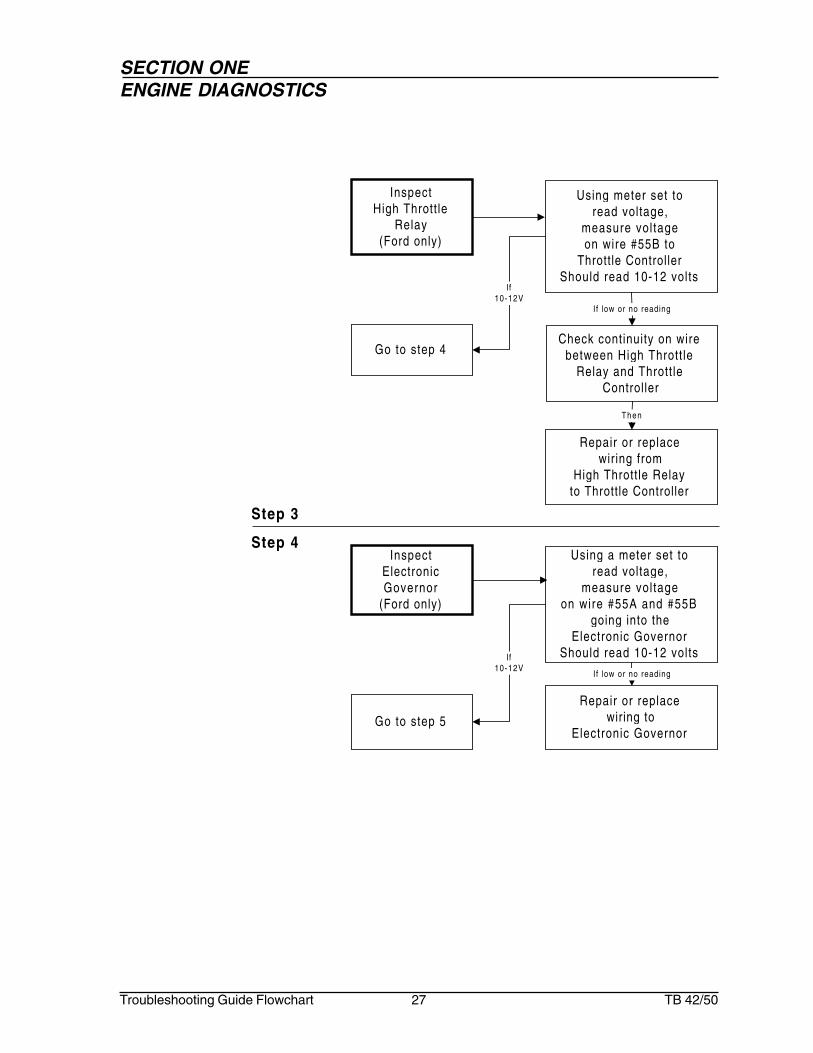
Step 3
Step 4
InspectHigh Thrott le
Relay(Ford only)
Using meter set toread voltage,
measure vol tageon wire #55B to
Throttle ControllerShould read 10-12 volts
If low or no reading
Check continuity on wirebetween High Thrott le
Relay and Thrott leController
Repair or replacewiring from
High Thrott le Relayto Throttle Controller
Then
Go to step 4
InspectElectronicGovernor
(Ford only)
Using a meter set toread voltage,
measure vol tageon wire #55A and #55B
going into theElectronic Governor
Should read 10-12 volts
If low or no reading
Repair or replacewiring to
Electronic GovernorGo to step 5
If10-12V
If10-12V

SECTION ONEENGINE DIAGNOSTICS
Troubleshooting Guide Flowchart 28 TB 42/50
Step 5
InspectActuator
Using a meter set toread voltage,
measure voltage,on wire #A1
and #A2 between theElectronic Governor
and SolenoidShould read 10-12 volts
If low or no reading
Repair or replaceElectronicGovernor
If10-12V
Repair or replace Electronic Governor
and/or wiring
Step 6
InspectThrottle Relay(Deutz only)
Using a meter set toread voltage,
measure vol tageon wire #55A betweenThrottle Circuit Breakerand Thrott le Solenoid
Should read 10-12 volts
If low or no reading
Check continuity on wirebetween Thrott leCircuit Breaker
and Thrott le Solenoid
Repair or replacewiring between
Throttle Circuit Breakerand Thrott le Solenoid
If no continuity
Go to step 7
If10-12V

SECTION ONEENGINE DIAGNOSTICS
Troubleshooting Guide Flowchart 29 TB 42/50
Step 7
Inspect Thrott le Solenoid
(Deutz)
Using meter set to readvoltage, measure voltage1. on wire #55A going
into Throttle Solenoid2. on wire #55A between
Thrott le Solenoid andground
Should read 10-12 volts
If low or no reading
Repair or replace Thrott le Solenoid
and/or Throttle Solenoid wiring
If problem sti l l exists
Adjust Thrott le Solenoid

SECTION ONEENGINE DIAGNOSTICS
Troubleshooting Guide Flowchart 30 TB 42/50
Step 1
Step 2
Engine overaccelerates
InspectElectronicGovernor
Using a meter set toread voltage,
measure voltage,on wire #55A and #55B
going into theElectronic Governor
Should read 10-12 volts
If low or no reading
Repair or replaceFord: wiring to
Electronic Governor
Go to step 2 If10-12V
InspectActuator
Using a meter set toread voltage,
measure vol tageon wire #A1
and #A2 between theElectronic Governor
and ActuatorShould read 10-12 volts
If low or no reading
Repair or replaceElectronicGovernor
If10-12V
Repair or replaceElectronic Governor
and/or wiring

SECTION ONEENGINE DIAGNOSTICS
Troubleshooting Guide Flowchart 31 TB 42/50
Circuit Breaker isopen
Step 1
Step 2
Engine will notstart fromplatform control
InspectPlatform ControlCircuit Breaker
(20 Amp)
Using a meter set to readvoltage, turn Ground/
Platform Switch to Platformposit ion, measure voltage
on wire #1 and #2entering Platform Control
Circuit BreakerShould read 10-12 volts
Check for voltage onwire #1B to Emergency
Stop SwitchShould read 10-12 volts
ResetCircuit Breaker
Then
If
Repair or replaceWire #1 and/or #2
Go to step 3
If10-12V
InspectGround/PlatformSelector Switch
Set Selector Switch toPlatform posit ion. Using ameter set to read voltage,
activate starter andmeasure vol tage betweenIgnit ion/Emergency Power
Switch and Ground/Platform Selector SwitchShould read 10-12 volts
Ground/PlatformSelector Switch isin Ground posit ion
Return Ground/Platform SelectorSwitch to Platform
posit ion
Then
If
Go to step 2 If10-12V
If low or no reading
ReplaceGround/Platform Selector
Switch and/orGround/Platform Selector
Switch wiring
ReplaceCircuit Breaker
If lowor no
reading
If lowor no
reading
If 10-12V

SECTION ONEENGINE DIAGNOSTICS
Troubleshooting Guide Flowchart 32 TB 42/50
Step 3
Step 4Inspect
Foot Switch andWir ing
Make sure Foot Switch isnot activated
Deactivate Foot SwitchIfnot
act ivated
Using a meter set to readvoltage, measure voltage
on wire #10 going intoFoot Switch and
wire #8 coming outof Foot Switch
Should be 10-12 volts
If act ivated
InspectEmergency Stop
Switch
Using a meter set to readvoltage, pul l Emergency
Stop Switch out andmeasure vol tage betweenEmergency Stop Switch
and Battery side ofPlatform Master Switch.Should read 10-12 volts
Emergency StopSwitch is off(pushed in)
If low or no readingPul l Emergency
Stop Switch (out)to the on posit ion
Then
If
ReplaceEmergency Stop Switch
and/orEmergency Stop Switch
wiringGo to step 4 If
10-12V
If low or no voltage
Repair or replaceFoot Switch
and/or wiring
If10-12VGo to step 5

SECTION ONEENGINE DIAGNOSTICS
Troubleshooting Guide Flowchart 33 TB 42/50
Step 5
InspectIgnit ion/Emergency
Power Switch
Using a meter set toread voltage, activate
engine starter andmeasure vol tage
on wire #4 betweenPlatform Master Switchand Ignit ion/Emergency
Power SwitchShould read 10-12 volts
Return to step 1 If10-12V
If low or no reading
ReplaceIgnit ion/Emergency Power
Switch and/orIgnit ion/Emergency Power
Switch wiring
Step 6
InspectPlatform Start
Switch
Using a meter set toread voltage, activate
Platform Start Switch andmeasure voltage onwire #4C between
Platform Start Switch andPlatform Emergency Power
SwitchShould read 10-12 volts
Go to step 6 If10-12V
If low or no reading
ReplacePlatform Start Switch
and/orPlatform Start Switch
wiring

SECTION ONEENGINE DIAGNOSTICS
Troubleshooting Guide Flowchart 34 TB 42/50
Step 1
Engine startswhile cranking,then dies whenkey switch isreleased
InspectRun Relay
Using a meter set toread voltage,
measure vol tageat Murphy Switch wire
#164, B post ofMurphy Switch
Should read 10-12 volts
If low or no reading
Repair or replaceRun Relay
and/orRun Relay wiring
Step 2
Go to step 2 If10-12V
InspectRun Solenoid
Using a meter set toread voltage,
measure vol tageon wire #8D between RunSolenoid Murphy SwitchShould read 10-12 voltsNote: Check continuity
to ground on whitejumper wire
If low or no reading
ReplaceRun Solenoid
and/orRun Solenoid wir ing
Go to step 3 If10-12V

SECTION ONEENGINE DIAGNOSTICS
Troubleshooting Guide Flowchart 35 TB 42/50
InspectVacuum Switch
(Ford only)
Check continuity on wirebetween Ignit ion and
Solenoid when switch is innormally closed posit ion
If no continuity
ReplaceVacuum Switch
Step 3


SECTION TWO:HYDRAULIC DIAGNOSTICS


SECTION TWOHYDRAULICS DIAGNOSTICS
Troubleshooting Guide Flowchart 39 TB 42/50
Hydraulic systemfunctions on
emergency poweronly
Go to Page42
InspectMain Hydraul ic Pump
Go to Page42
InspectSense L ine Dump Valve
Hydraulic pumpstays on stroke
Go to Page44
InspectCompensator Valve
Chart 1
Chart 2
OK
Step 1
Step 2
Step 1
Go to Page43
InspectBlocking Valve Relay and Wir ing
OKStep 3
Go to Page43
InspectBlocking Valve
OKStep 4
Hydraulic oiloverheats
while idling
Go to Page45
InspectBlocking Valve
Chart 3
Step 1
Go to Page45
InspectSteer Level Valve
OKStep 2

SECTION TWOHYDRAULICS DIAGNOSTICS
Troubleshooting Guide Flowchart 40 TB 42/50
Hydraulic oiloverheats
during operation
Go to Page46
InspectFunct ions Valve
Hydraulic functionsare sluggish
Go to Page47
InspectEng ine RPM
Go to Page47
InspectPump Pressure
Go to Page48
InspectAccumulator
Go to Page48
InspectF low f rom Pump
Chart 4
Chart 5
OK
OK
OK
Step 1
Step 2
Step 3
Step 4
Step 1
Hydraulic pump willnot build pressure
Go to Page49
InspectCompensator Valve
Chart 6
Step 1

SECTION TWOHYDRAULICS DIAGNOSTICS
Troubleshooting Guide Flowchart 41 TB 42/50
Flow fromhydraulic pump
is too low
Go to Page51
InspectHydrau l ic Pump Compensator
Flow fromhydraulic pump
is too high(kills engine)
Go to Page51
InspectFlow Adjustment on
Main Hydraul ic Pump
Chart 8
Chart 9
Step 1
Step 1
Hydraulic pumpwill not build
enough pressure
Go to Page50
InspectCompensator Valve
Go to Page50
InspectSensel ine Dump Valve
Chart 7
OK
Step 1
Step 2

SECTION TWOHYDRAULICS DIAGNOSTICS
Troubleshooting Guide Flowchart 42 TB 42/50
Inspect Main Hydraulic
Pump
Remove gaugeand
Go to step 2
CheckMain Hydraul ic Pump,
Pump Coupl ing andPump Compensator
Install 1000 psi pressuregauge to hydraul ic pumptest plug. Set engine for
idle and measuredifferential/standby
pressure.Should read 350 psi
If reading is abnormal
ReplaceMain Hydraul ic Pump
and/orPump Coupl ing
and/orPump Compensator
If malfunct ioning
Hydraulicsystemfunctions onemergencypower only
Step 1
Step 2
If350 psi
Inspect Sense Line Dump
Valve
Check seals onSense Line Dump
Valve
If10-12V
Repair or replaceSense Line Dump Valve
and/or wiring
Using a meter set to readvoltage, activate Ground
Control Switch andmeasure vol tage
1.on wire #28B betweenTerminal Stripin Junction Box andSense Line Dump Valve
2.on wire # 28B atSense Line Dump Valve
Should read 10-12 volts
If low or no reading
Repair or replaceSense Line Dump Valve
If bad
O k
Go to step 3

SECTION TWOHYDRAULICS DIAGNOSTICS
Troubleshooting Guide Flowchart 43 TB 42/50
Step 3
Step 4
InspectBlocking Valve
Relay and Wires
Go to step 4
Repair or replaceBlocking Valve Relay
and/orBlocking Valve Relay wiring
Using a meter set to readcontinuity , activate Steer
Micro-Switch andcheck for ground
1. on wire #100 betweenTerminal Strip inJunct ion Box andRelay
2. on wire #100 enteringRelay
If no continuity
Ifcontinuity
InspectBlocking Valve
Return to step 1Repair or replace
Blocking Valve Cartr idge
Visually check BlockingValve Cartridge for
binding
Should normally be open.
If stuckIf
O k

SECTION TWOHYDRAULICS DIAGNOSTICS
Troubleshooting Guide Flowchart 44 TB 42/50
Hydraulicpump stays onstroke
Step 1
InspectCompensator
Valve
Check seals onSense Line Dump
Valve
Ifgoes
offs t roke
Repair or replaceCompensator
Remove hose f romcompensator
Recheck pressure onPump
If stays on stroke
Repair or replaceSense Line Dump
Valve
If bad

SECTION TWOHYDRAULICS DIAGNOSTICS
Troubleshooting Guide Flowchart 45 TB 42/50
Step 1
Step 2
Hydraulic oiloverheatswhile idling
InspectSteer Level Valve
Repair or replaceSteer Level Valve
Manually depressoverrides to center the
spools
If stuck
InspectBlocking Valve
Go to step 2Repair or replace
Blocking Valve Cartr idge
Visually check BlockingValve Cartridge for
binding
Should normally be open.
If stuckIf
O k
Machine function wil l bemoving when manualoverride is activated.

SECTION TWOHYDRAULICS DIAGNOSTICS
Troubleshooting Guide Flowchart 46 TB 42/50
Hydraulic oiloverheatsduringoperation
Step 1
InspectFunctions Valve
Repair or replaceFunctions Valve
SwitchManual Overr idesto the On posit ion
Heat ing stops
Heat ingcont inues
Repair or replaceHosing

SECTION TWOHYDRAULICS DIAGNOSTICS
Troubleshooting Guide Flowchart 47 TB 42/50
Step 1
Step 2
Hydraulicfunctions aresluggish
InspectEngine RPM
AdjustThrott le Actuator
Use a Tachometer tomeasure Engine RPM
Should read:Ford - 1050 RPM at Low 2100 RPM at Mid 2800 RPM at HighDeutz -1200 RPM at Low 2800 RPM at High
If not
Go to step 2 If correctR P M
InspectPump Pressure
AdjustPump Compensator
Install 1000 psipressure gauge at
Test Port.Set engine for idle
and measure standbypressure.
Should read 300 psi
If low or no reading
Remove gaugeand
Go to step 3
If300 psi

SECTION TWOHYDRAULICS DIAGNOSTICS
Troubleshooting Guide Flowchart 48 TB 42/50
Step 3
Step 4
InspectAccumulator
RechargeAccumulator
Measure the chargeon the Accumulator
Should be 750 to 800 psi
If low or no reading
Go to step 4
If750 to 800 psi
InspectFlow from Pump
AdjustFlow Ajustment
With chassis raised(all wheels off the ground)and adequately supported,
1.Instal l a Flowmeter onthe discharge side ofpump.
2.Install a 1000 psipressure gauge at TestPort on Accumulator.Start engine and turnThrottle Switch to high.Activate drive functionfull on.
Flowmeter should read12 to14 gpm and
pressure gauge shouldread 300 psi
If low or no reading
Remove gaugesand
Return to step 1
If12 to
14 gpmand
300 psi

SECTION TWOHYDRAULICS DIAGNOSTICS
Troubleshooting Guide Flowchart 49 TB 42/50
Step 1
Step 2
Hydraulic pumpwill not buildpressure Inspect
CompensatorValve
Go to step 2
Remove hoses f romSense Line Dump Valveto Compensator Valve
and reattach toPressure Line. Using a
5000 psi pressure gaugecheck pressure.
Should read 2500 psi
If low or no reading
Remove gauge andcheck seals on
Sense Line Dump Valve
Repair or replaceSense Line Dump Valve
If bad
If 2500 psi
InspectPump Coupl ing
Repair or replacePump Coupl ing
RemoveMain Hydraul ic Pump
visually checkPump Coupl ing
If bad
O k
Repair or replaceCompensator
and/orMain Hydraul ic Pump

SECTION TWOHYDRAULICS DIAGNOSTICS
Troubleshooting Guide Flowchart 50 TB 42/50
Step 1
Step 2
Hydraulic pumpwill not buildenough pressure Inspect
CompensatorValve
Go to step 2
Remove hoses f romSense Line Dump Valveto Compensator Valve
and reattach toPressure Line. Using a
5000 psi pressure gaugecheck pressure
Should read 2500 psi
If low or no reading
Remove gauge andcheck seals on
Sense Line Dump Valve
Repair or replaceSense Line Dump Valve
If bad
If 2500 psi
Inspect Sense Line Dump
Valve
Check seals onSense Line Dump
Valve
If10-12V
Repair or replaceSense Line Dump Valve
wiring
Using meter set to readvoltage, activate Ground
Control Switch andmeasure vol tage
1. On wire #28B betweenTerminal Strip inJunction Box andSense Line Dump Valve
2. On wire # 28B atSense Line DumpValve
Should read 10-12 volts
If low or no reading
Repair or replaceSense Line Dump Valve
If bad

SECTION TWOHYDRAULICS DIAGNOSTICS
Troubleshooting Guide Flowchart 51 TB 42/50
Step 1
Step 1
Inspect Hydraul ic Pump
Compensator
Adjust Differential/StandbyAdjustment on Pump
compensator to 300 psi
Install 1000 psi pressuregauge to actuator test plug.
Set engine for idle andmeasure differential/
standby pressure.Should read 300 psi
If reading is to low
ReplacePump Compensator
and/orPump Coupl ing
Wil l not adjust or errat ic
Flow fromhydraulicpump istoo low
Flow fromhydraulicpump istoo high(kills engine)
InspectFlow Adjustment
on Main HydraulicPump
Visually check FlowAdjustment Screw on Main
Hydraul ic PumpScrew should extend
between 3/4" and 7/8" from face of pump
ResetFlow Adjustment on Main
Hydraul ic Pump


SECTION THREE:STEERING SYSTEM DIAGNOSTICS


SECTION THREESTEERING SYSTEM DIAGNOSTICS
Troubleshooting Guide Flowchart 55 TB 42/50
Machine will notsteer
Go to Page56
InspectMicro-Switch for Blocking Valve
(at steer control ler)
Go to Page56
InspectBlocking Valve Solenoid and
Solenoid Wir ing
Go to Page57
InspectSteer Micro Switch (Right)
Go to Page58
InspectSteer Micro Switch (Left)
Go to Page58
InspectSteer Control Valve
Go to Page59
InspectCenter Post
OK
OK
OK
OK
OK
Chart 1
Step 1
Step 2
Step 4
Step 5
Step 6
Step 7
Go to Page57
InspectBlocking Valve
OKStep 3
Go to Page59
InspectTow Package Float Valve
OKStep 8

SECTION THREESTEERING SYSTEM DIAGNOSTICS
Troubleshooting Guide Flowchart 56 TB 42/50
InspectMicro-Switch forBlocking Valve
(at steer controller)
Go to step 2 Ifcontinuity
ReplaceSteer Micro Switch
and/orSteer Micro Switch wiring
Using a meter set to readcontinuity, activate SteerMicro-Switch and check
for ground1. on wire #100 between
Steer Micro-Switch andJunction Box
2. at wire #100 inJunct ion Box
Should show continuity toground
If no continuity
Machine willnot steer
Step 1
Step 2
Note:At this point the manualoverride may also beuse to isolatethe solenoid, howeveruse caution as themachine wil l be moving.
InspectBlocking Valve
Relay and Wires
Go to step 3
Repair or replaceBlocking Valve Relay
and/orBlocking Valve Relay wiring
Using a meter set to readcontinuity , activate Steer
Micro-Switch andcheck for ground
1. on wire #100 betweenTerminal Strip inJunct ion Box andRelay
2. on wire #100 enteringRelay
If no continuity
Ifcontinuity

SECTION THREESTEERING SYSTEM DIAGNOSTICS
Troubleshooting Guide Flowchart 57 TB 42/50
Step 3
Step 4Inspect
Steer Micro-Switch(Right)
Go to step 5 If10-12V
ReplaceSteer Micro-Switch
(Solenoid)and/or
Steer Micro-Switch(Solenoid) wiring
Using a meter set toread voltage, activate
Steer Right Switch andmeasure vol tage
1. on wire #20 betweenSteer Micro-Switch(Right) and SteerControl Valve
2. on wire #20 at SteerControl Valve
Should read 10-12 volts
If low or no reading
InspectBlocking Valve
Go to step 4Repair or replace
Blocking Valve Cartr idge
Visually check BlockingValve Cartridge for
binding
Should normally be open.
If stuckIf
O k
Note:At this point the manualoverride may also beuse to isolatethe solenoid, howeveruse caution as themachine wil l be moving.

SECTION THREESTEERING SYSTEM DIAGNOSTICS
Troubleshooting Guide Flowchart 58 TB 42/50
Step 5
Step 6Inspect
Steer ControlValve
Go to step 7 ReplaceSteer Control Valve
ActivatingManual Overr ides and
check pressure
Should be 1500 psi
If lower than 1500 psi
I f approx.1500 ps i
InspectSteer Micro-Switch
(Left)
Go to step 6 If10-12V
ReplaceSteer Micro-Switch
(Solenoid)and/or
Steer Micro-Switch(Solenoid) wiring
Using a meter set toread voltage, activate
Steer Right Switch andmeasure vol tage
1. on wire #19 betweenSteer Micro-Switch(Left) and Steer ControlValve
2. on wire #19 at SteerControl Valve
Should read 10-12 volts
If low or no reading
During activation ofsteering function themachine wil l be moving.

SECTION THREESTEERING SYSTEM DIAGNOSTICS
Troubleshooting Guide Flowchart 59 TB 42/50
Step 7
InspectCenter Post
Repair or replaceSteer Cylinder
Note: Machineswith optional
Tow Packagego to step 8
Ifreading
isnormal
Repair or replaceCenter Post
Remove hoses leading to Steer Cylinder Plug
hoses andcap the Steer Cylinder.
While activatingsteering function,
check for 1500 psi atthe pump pressure Test
Port
If reading is abnormal
InspectTow Package Float
Valve
Refer to Chapter 12Accessories Diagnostics
During activation ofsteering function themachine wil l be moving.
Step 8


SECTION FOUR:DRIVE SYSTEM DIAGNOSTICS


SECTION FOURDRIVE SYSTEM DIAGNOSTICS
Troubleshooting Guide Flowchart 63 TB 42/50
Drive system is notoperational with
controller in eitherdirection
Go to Page67
InspectFoot Swi tch
Go to Page67
InspectDrive Circui t Breaker (3 amp)
Go to Page68
InspectControl ler Circui t Board and S1
Micro Swi tch Wir ing
Go to Page68
InspectS1 Micro-Switch ( in Control ler)
Go to Page69
InspectControl ler Circui t Board
Go to Page69
InspectPotent iometer
Go to Page70
InspectS2 Micro-Switch ( in Control ler)
Go to Page70
InspectDr ive Solenoid
Go to Page71
InspectDrive Control Valve
Go to Page71
InspectCenter Post
Go to Page72
InspectShutt le Valve Port ion of Dual
Counterbalance Valve
OK
OK
OK
OK
OK
OK
OK
OK
OK
OK
Chart 1
Step 1
Step 2
Step 3
Step 4
Step 5
Step 6
Step 7
Step 8
Step 9
Step 10
Step 11

SECTION FOURDRIVE SYSTEM DIAGNOSTICS
Troubleshooting Guide Flowchart 64 TB 42/50
No forward drive(reverse ok)
Go to Page73
InspectS2 Micro-Swi tch
(in Drive Control ler)
Go to Page73
InspectDrive Control ler Circui t Board
Go to Page74
Solenoid(Drive Forward on Control Valve)
Go to Page74
InspectDual Counterbalance Cartr idge
No reverse drive(forward ok)
Go to Page75
InspectS2 Micro-Swi tch
(in Drive Control ler)
Go to Page75
InspectDrive Control ler Circui t Board
Go to Page76
InspectSolenoid Valve
(Drive reverse on Control Valve)
Go to Page76
InspectDual Counterbalance Cartr idge
OK
OK
OK
OK
OK
OK
Chart 2
Chart 3
Step 1
Step 2
Step 3
Step 4
Step 1
Step 2
Step 3
Step 4

SECTION FOURDRIVE SYSTEM DIAGNOSTICS
Troubleshooting Guide Flowchart 65 TB 42/50
InspectPower to R Terminal
Drive high rangenot operating
Go to Page77
InspectDr ive Low/High Range Swi tch
Go to Page77
InspectBoom Posi t ion and/orBoom Limi ts Swi tch
Go to Page78
InspectRange Valve
Go to Page78
Machine drives atfull speed withplatform raised
and/or extended
Go to Page80
InspectBoom Limi ts Swi tch
Go to Page80
InspectRange Valve
OK
OK
OK
OK
Chart 4
Chart 5
Brakes will notrelease
Go to Page81
InspectBrake Pressure
Chart 6
Step 1
Step 2
Step 3
Step 4
Step 1
Step 2
Step 1
InspectSelector Spool in Transmission
Package
Go to Page79
OKStep 5

SECTION FOURDRIVE SYSTEM DIAGNOSTICS
Troubleshooting Guide Flowchart 66 TB 42/50
Only one wheelturns
(2 wheel drive)
Go to Page82
InspectCase Drain
Go to Page82
InspectSelector Valve
One wheel turnsfaster than other(2 wheel drive)
OK
Chart 7
Chart 8
Step 1
Step 2
Go to Page83
InspectCase Drain
Go to Page83
InspectSelector Valve
OK
Step 1
Step 2

SECTION FOURDRIVE SYSTEM DIAGNOSTICS
Troubleshooting Guide Flowchart 67 TB 42/50
InspectFoot switch
Using a meter set toread voltage, activate
Foot Switch andmeasure vol tage
1. on wire #9 betweenFoot Switch and DriveCircuit Breaker
2. at 3 amp DriveCircuit Breaker
Should read 10-12 volts
If low or no voltage
ReplaceFoot Switch
and/orFoot Switch wiring
Go to step 2 If10-12V
Drive system isnon-operationalwith controllerin eitherdirection
Step 1
Step 2Inspect
Drive CircuitBreaker (3 amp)
Using a meter set toread voltage, activate
Foot Switch andmeasure vol tage
1. on wire #69 betweenCircuit Breaker andDrive Controller
2. at positive (+) post ofDrive controller
Should read 10-12 volts
If low or no voltage
ReplaceFoot Switch
and/orFoot Switch wiring
Go to step 3 If10-12V

SECTION FOURDRIVE SYSTEM DIAGNOSTICS
Troubleshooting Guide Flowchart 68 TB 42/50
Step 3
Step 4
InspectController Circuit
Board and S1Micro-Switch
Wir ing
Using a meter set toread voltage, activate
Foot Switch andmeasure vol tage
1. on red wire fromCircuit Board toS1 Micro-Switch
2. at red wire ofS1 Micro-Switch
Should read 10-12 volts
If low or no voltage
ReplaceCircuit Board
and/orS1 Micro-Switch wiring
Go to step 4 If10-12V
InspectS1 Micro-Switch
(in Controller)
Using a meter set toread voltage, step on
Foot Switch andactivate Controller,
measure vol tage1. on black wire between
S1 Micro-Switch andController Circuit Board
2. at point where blackwire from S1 Switchenters Controller CircuitBoard
Should read 10-12 volts
ReplaceS1 Micro-Switch
(in Controller)and/or
S1 Micro-Switchwiring
Go to step 5
If low or no voltage
Move control ler handle ineither direction andobserve red LED on
Circuit Board Controller
If not litIf lit

SECTION FOURDRIVE SYSTEM DIAGNOSTICS
Troubleshooting Guide Flowchart 69 TB 42/50
Step 5
Step 6
Using a meter set toread voltage, step on
Foot Switch andactivate Controller,
measure vol tage1. on green wire to
Potent iometer fromController Circuit Board
2. on wire betweenController Circuit Board
and Potent iometerShould read 10-12 volts
If low or no voltage
ReplaceController Circuit Board
and/orController Circuit Board
wiring
Go to step 6 If10-12V
InspectController Circuit
Board
InspectPotent iometer
Using a meter set to ohms,measure reading across1. green wire and purple
wire between Control lerCircuit Board andPotent iometer
2. green wire and orangewire between Control lerCircuit Board andPotent iometerReading should vary
according to Controllermovement
If no reading
Check continuity on wirebetween Controller CircuitBoard and Potent iometer
Go to step 7
continuity
ReplacePotent iometer
and/orPotent iometer
wiring
No cont inui ty

SECTION FOURDRIVE SYSTEM DIAGNOSTICS
Troubleshooting Guide Flowchart 70 TB 42/50
Step 7
Step 8
InspectS2 Micro-Switch
(in Controller)
Using a meter set toread voltage, step on
Foot Switch and activateController, perform the
following:1. While activating
controller in forwardmode measureproportional voltage atController Circuit Boardwhere white wire entersfrom S2 Micro-Switch
2. While activatingController in reversemode measureproportional voltage atController Circuit Boardwhere blue wire entersfrom S2 Micro-Switch
Reading should varyaccording to amount of
reverse movement
Check continuity on bluewire and on white wire
between Controller CircuitBoard and S2 Micro-Switch
ReplaceS2 Micro-Switch
and/orS2 Micro-Switch wiring
No Cont inui ty
Go to step 8
If no reading
Continui ty
Push Manual Overr idewhile activating variouscontroller functions and
check operation.
If funct ions are abnormal or errat ic
Replace Drive Section Control Valve
Go to step 9
InspectDrive Solenoid
If functionsare normal
Machine function wil l bemoving when manualoverride is activated.

SECTION FOURDRIVE SYSTEM DIAGNOSTICS
Troubleshooting Guide Flowchart 71 TB 42/50
Step 9
Step 10
Remove hoses from dr ivesection of Control Valve.Plug the hoses and capvalve. Install a 5000psi
pressure gauge toPump Test Port.
While activating drivecontrol function, check
pressure.Should read 2500 psi
(while activating function)
If funct ions are abnormal or errat ic
ReplaceValves on Drive Section
of Control Valve
Remove gauge andGo to step 10
InspectDrive Control
Valve
If functionsare normal
InspectCenter Post
Remove hoses at V1 andV2 ports of Dual
Counterbalance Valve.Plug hoses and cap valve.Instal l a 5000psi pressure
test gauge toPump Test Port
While activating drivecontrol function, check
pressure.Should read 2500 psi
(while activating function)
If pressures are abnormal or errat ic
Repair or replaceCenter Post
Remove gauge andGo to step 11
If pressuresare normal

SECTION FOURDRIVE SYSTEM DIAGNOSTICS
Troubleshooting Guide Flowchart 72 TB 42/50
Step 11
Install a 5000 psi pressuretest gauge to BR port of
Dual CounterbalanceValve. Note if pressure isequal to drive pressure.
unequal pressure
ReplaceShuttle Valve (in Dual
Counterbalance Valve)
Return to step 1
equalpressure
InspectShutt le Valve
Portion of DualCounterbalance
Valve

SECTION FOURDRIVE SYSTEM DIAGNOSTICS
Troubleshooting Guide Flowchart 73 TB 42/50
Step 1
Step 2
No forwarddrive(Reverse Ok)
InspectDrive Controller
Circuit Board
Using a meter set toread voltage, activate drive
funct ion and measureproportional voltage at
Terminal A ofCircuit Board.
Reading should varyaccording to controller
movement .
If no or errat ic reading
ReplaceDrive Controller Circuit
Board
Go to step 3 Ifnormal
InspectS2 Micro-Switch
(in DriveController)
Go to step 2 Ifnormal
Check continuity on bluewire between S2 Micro-
Switch and Control lerCircuit Board
Using a meter set toread voltage, activatefunct ion and measureproportional voltage atController Circuit Boardat point where blue wire
from S2 Micro-Switchenters.
Reading should varyaccording to controller
movement .
If low or no reading
ReplaceS2 Micro-Switch
and/orS2 Micro-Switch wiring
no cont inuity

SECTION FOURDRIVE SYSTEM DIAGNOSTICS
Troubleshooting Guide Flowchart 74 TB 42/50
Step 3
Step 4
Replace theDual Counterbalance Valve
Cartr idge tested
InspectDual
CounterbalanceValve Cartr idge
Using a 5000psi pressuretest gauge activate drive
funct ion and check systempressure at hose entering
port M1 on CounterbalanceValve
If no pressure reading
ReplaceDrive Forward Solenoid
Valve and/orDrive Forward Solenoid
Valve wiring
InspectSolenoid Valve(Drive forward
on Control Valve)
Go to step 4
Try manual override
Using a meter set to readvoltage. While activating
forward function, measureproportional voltage at wire
#17 on Drive section ofControl Valve.
Reading should varyaccording to controller
movement .
If no reading
Overr ide al lows operat ion
Overr idedoes not
al lowoperat ion
Machine function wil l bemoving when manualoverride is activated.
SECTION FOURDRIVE SYSTEM DIAGNOSTICS
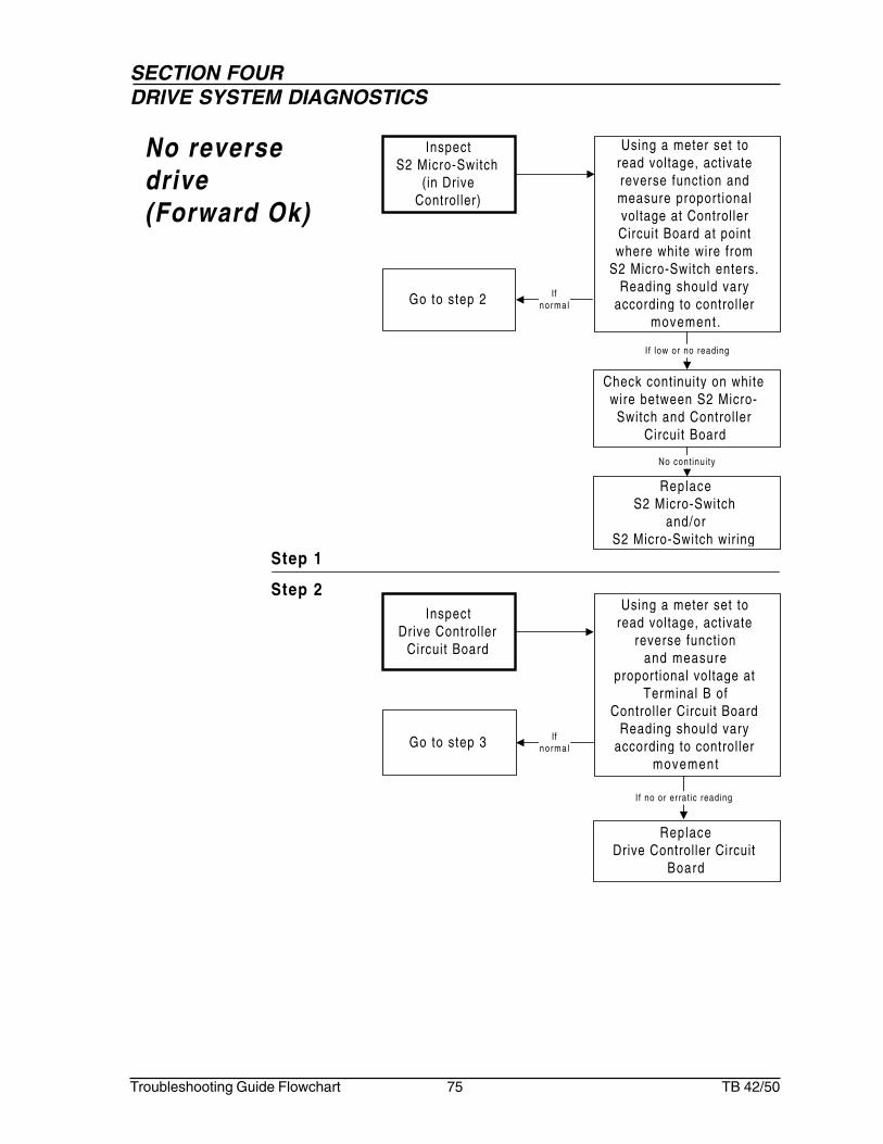
Troubleshooting Guide Flowchart 75 TB 42/50
Step 1
Step 2
No reversedrive(Forward Ok)
InspectDrive Controller
Circuit Board
Using a meter set toread voltage, activate
reverse functionand measure
proportional voltage atTerminal B of
Controller Circuit BoardReading should vary
according to controllermovement
If no or errat ic reading
ReplaceDrive Controller Circuit
Board
Go to step 3 Ifnormal
InspectS2 Micro-Switch
(in DriveController)
Go to step 2 Ifnormal
Check continuity on whitewire between S2 Micro-
Switch and Control lerCircuit Board
Using a meter set toread voltage, activatereverse function andmeasure proport ionalvoltage at ControllerCircuit Board at pointwhere white wire from
S2 Micro-Switch enters.Reading should vary
according to controllermovement .
If low or no reading
ReplaceS2 Micro-Switch
and/orS2 Micro-Switch wiring
No cont inui ty

SECTION FOURDRIVE SYSTEM DIAGNOSTICS
Troubleshooting Guide Flowchart 76 TB 42/50
Step 3
Step 4
Replace theDual Counterbalance Valve
Cartr idge tested
InspectDual
CounterbalanceValve Cartr idge
Using pressure test gaugeactivate drive function andcheck system pressure athose entering port M2 on
Counterbalance Valve
If no pressure reading
ReplaceDrive Reverse
Solenoid Valve and/orDrive Reverse Solenoid
Valve wiring
InspectSolenoid Valve
(Drive reverse onControl Valve)
Go to step 4
Try manual override
Using a meter set to readvoltage. While activating
reverse function,measure proport ionalvoltage at wire #18 on
Drive section ofControl Valve.
Reading should varyaccording to controller
movement .
If no reading
Overr ide al lows operat ionOverr idedoes not
al lowoperat ion
Machine function wil l bemoving when manualoverride is activated.

SECTION FOURDRIVE SYSTEM DIAGNOSTICS
Troubleshooting Guide Flowchart 77 TB 42/50
Posit ion Booms to ful lyretracted and down
posit ion
Adjust Boom Retract/DownLimit Switch
InspectBoom Posit ion
and/orBoom Limit Switch
Booms are not posit ionedfor High Range speed
operations
Boom Limit Switch arenot Adjusted
Step 1
Step 2
Drive highrange notoperating
InspectDrive Low/HighRange Switch
Go to step 2 If10-12V
Using a meter set to readvoltage, measure voltage1. on wire #4C going into
the Low/High DriveRange Switch
2. on wire #11 coming outof the Low/High DriveRange Switch.
Should read 10-12 volts
If low or no reading
ReplaceDrive Low/High Range
Switchand/or
Drive Low/High RangeSwitch wiring
Check for 10-12volts at wire #11A
at Boom LimitSwitch
stillnot
operat ing
Repair or replaceBoom Limit Switch
If no voltage
Go to step 3
If10-12V

SECTION FOURDRIVE SYSTEM DIAGNOSTICS
Troubleshooting Guide Flowchart 78 TB 42/50
Step 3
Step 4
InspectRange Valve
Check forblockage in Drive
Range Valveand/or hoses
Using a 5000 psi pressuregauge, measure pressureon hose between RangeValve and Center Post.Should read 2500 psi
If no reading
Repair or replaceRange Valve
Go to step 4
Ifpressure
is low
Return to step 2
InspectPower to R
Terminal
Go to step 5
With Boom retracted andlowered, use a meter setto read voltage, measurevoltage at the R Terminal
of Drive ControllerShould read 10-12 volts
If no reading If10-12V
Check connect ionon Boom Wirebetween BoomSwitches and
Platform
Iflow
Using meter set to readvoltage, measure voltageat Range Valve wire #34.Should read 10-12 volts
If10-12V
If 2500 psi
SECTION FOURDRIVE SYSTEM DIAGNOSTICS
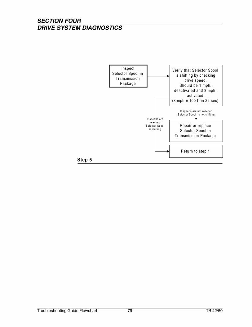
Troubleshooting Guide Flowchart 79 TB 42/50
Step 5
Repair or replaceSelector Spool in
Transmission Package
InspectSelector Spool in
TransmissionPackage
Return to step 1
Verify that Selector Spoolis shift ing by checking
drive speed.Should be 1 mph.
deact ivated and 3 mph.activated.
(3 mph = 100 ft in 22 sec)
If speeds are not reachedSelector Spool is not shif t ing
I f speeds arereached
Selector Spoolis shift ing

SECTION FOURDRIVE SYSTEM DIAGNOSTICS
Troubleshooting Guide Flowchart 80 TB 42/50
Step 1
Step 2
Machinedrives at fullspeed withplatformraised and/orextended
InspectBoom Limits
SwitchBoom Limits Switch aresticking or not properly
Adjusted
Repair, replace or readjustBoom Limits Switch
InspectRange Valve
Using a 5000 psi pressuregauge, measure pressureon hose between RangeValve and Center Post
Should read 0 psi
If 2500 psi
Repair or replaceRange Valve
Check for stuckSelector Valve on
Transmission Package
If0 psi
Go to step 2prob lem
stillexists

SECTION FOURDRIVE SYSTEM DIAGNOSTICS
Troubleshooting Guide Flowchart 81 TB 42/50
Brakes will notrelease
Step 1
InspectBrake Pressure
1. Install a 5000psipressure gauge in BRPort on Motion ControlValve
2. Take pressure readingat Pump Compensator
Readings should besimilar
Repair or replaceBrake Shutt le Valve

SECTION FOURDRIVE SYSTEM DIAGNOSTICS
Troubleshooting Guide Flowchart 82 TB 42/50
Step 1
Step 2
Only onewheel turns(2 wheel drive)
InspectCase Drain
Disconnect exist ing hose,install a f lowmeter
between exist ing hoseand Drive Motor.
Should be no morethan .5 gpm
If morethan .5 gpm
Repair or replaceDrive Motor
Go to step 2
If lessthan
.5 gpm
InspectSelector Valve
Visually check for oilleakage around Pilot Block
and Main Block.
ReplaceO'rings
Ifb lown
Inspect Quad Rings onSelector Spool
Remove Pi lot Block andinspect O'rings on Pilot
spool
If leakage exist
I f O'r ings Ok
ReplaceQuad Rings
Ifb lown
Check rel ief Valve onTransmission Valve
If Quad Rings Ok
Adjust Relief Valvefor 2500 psi
IfO k
Check f low control acrossFlow Divider Combiner
If problem sti l l exists
Adjust FlowControl for proper
operation
IfO k
Note:I f machine is equippedwith Tow Package Optionmake sure Hubs areengaged.

SECTION FOURDRIVE SYSTEM DIAGNOSTICS
Troubleshooting Guide Flowchart 83 TB 42/50
Step 1
Step 2
One wheelturns fasterthan other(2 wheel drive)
InspectCase Drain
Disconnect exist ing hose,install a f lowmeter
between exist ing hoseand Drive Motor.
Should be no morethan .5 gpm
If morethan .5 gpm
Repair or replaceDrive Motor
Go to step 2
If lessthan
.5 gpm
InspectSelector Valve
Visually check for oilleakage around Pilot Block
and Main Block.
ReplaceO'rings
Ifb lown
Inspect Quad Rings onSelector Spool
Remove Pi lot Block andinspect O'rings on Pilot
spool
If leakage exist
I f Ok
ReplaceQuad Rings
Ifb lown
Check rel ief Valve onTransmission Valve
If Quad Rings Ok
Adjust Relief Valvefor 2500 psi
IfO k
Check f low control acrossFlow Divider Combiner
If problem sti l l exists
Adjust FlowControl for proper
operation
IfO k


SECTION FIVE:EMERGENCY POWER SYSTEM DIAGNOSTICS


SECTION FIVEEMERGENCY POWER SYSTEM DIAGNOSTICS
Troubleshooting Guide Flowchart 87 TB 42/50
Emergency pumpmotor non-operational
Go to Page88
InspectEmergency Power Swi tch
Go to Page89
InspectEmergency Power Solenoid
and Wir ing
Go to Page89
InspectEmergency Power Uni t
No functions whenon emergency
power
Go to Page90
InspectBlocking Valve
OK
OK
Chart 1
Chart 2
Step 2
Step 3
Step 4
Step 2
Go to Page88
InspectBat tery and Cable Connect ions
OK
Step 1
Go to Page90
InspectBat tery and Cable Connect ions
OK
Step 1
Go to Page91
InspectEmergency Power Pump
OKStep 3

SECTION FIVEEMERGENCY POWER SYSTEM DIAGNOSTICS
Troubleshooting Guide Flowchart 88 TB 42/50
Repair or ReplaceEmergency Power SwitchTerminal wiring (wire #6)
and/orEmergency Power
Solenoid wiring (wire #6A)and/or
Emergency Power Switch
InspectEmergency Power
Switch
Go to step 3
Check continuity1. on wire #6 between
Emergency PowerSwitch and TerminalStrip in Control Box
2. between wire #6 ofTerminal Strip inJunction Box and wire#6A at EmergencyPower Solenoid
Using a meter set toread voltage, activate
Emergency Power andmeasure vol tage
1. on wire #6 ofEmergency PowerSwitch
2. at Emergency PowerSolenoidShould be 10-12 volts
If no reading
If10-12V
Step 1
Step 2
Emergencypump motornon-operational
No cont inui ty
InspectBatteries
Using a meterset to read
voltage, checkeach battery for
12 volts whileunder load
Recharge orreplace
battery(s)
Check batteryconnect ions
If loose
If low or no voltage
Clean allconnect ions
Tighten allconnect ions
Ifcorroded
If 12V
Batteries omit hydrogenand oxygen elements thatcan combine explosively.Do not smoke or permitopen f lames or sparkswhen checking batteries

SECTION FIVEEMERGENCY POWER SYSTEM DIAGNOSTICS
Troubleshooting Guide Flowchart 89 TB 42/50
Step 3
Repair or ReplaceEmergency Pump Motor
InspectEmergency Power
Unit
I f previous checks havebeen performed and found
to be normal, checkEmergency Pump Motor
for internal groundingcondit ion
Repair or ReplaceWiring from Battery
Disconnect Switch toEmergency Power
Solenoid and/or Emergency Power Unit
wiring and/orEmergency Power
Solenoid
InspectEmergency Power
Solenoidand Wir ing
Go to step 4
Check continuity1. on wire between
Battery DisconnectSwitch and EmergencyPower Solenoid
2. on wire betweenEmergency PowerSolenoid and PumpMotor
Using a meter set to readvoltage, measure voltage1. at Emergency Power
Solenoid and fromBattery DisconnectSwitch
2. act ivate EmergencyPower Switch andmeasure voltage atEmergency PumpMotor
Should be 10-12 volts
If no reading
If10-12V
No cont inui ty
Step 4

SECTION FIVEEMERGENCY POWER SYSTEM DIAGNOSTICS
Troubleshooting Guide Flowchart 90 TB 42/50
Step 1
No functionswhen onemergencypower
Step 2
InspectBatteries
Using a meterset to read
voltage, checkeach battery for
12 volts whileunder load
Recharge orreplace
battery(s)
Check batteryconnect ions
If loose
If low or no voltage
Clean allconnect ions
Tighten allconnect ions
Ifcorroded
If 12V
Batteries omit hydrogenand oxygen elements thatcan combine explosively.Do not smoke or permitopen f lames or sparkswhen checking batteries
Repair or ReplaceEmergency Power Pump
Unit
InspectEmergency Power
Pump
Attach 5000 psi pressuregauge to discharge
side of Emergency PowerPump, act ivate
Emergency Power Pumpand Ground Control Switch
or Foot Switch.Should read
2500-2750 psi.
If reading is abnormal or errat ic
Remove gaugeand
Go to step 3
IfO k

SECTION FIVEEMERGENCY POWER SYSTEM DIAGNOSTICS
Troubleshooting Guide Flowchart 91 TB 42/50
Step 3
InspectBlocking Valve
Refer back toChapter 3, Chart 1
Step 3
Repair or replaceBlocking Valve Cartr idge
With Ground ControlSwitch activated, use a
meter set to read voltageand measure vol tage
on wire #100B toBlocking Valve SolenoidShould be 10 to 12 volts
If 10 to 12V
Ifno vol tage


SECTION SIX:SWING SYSTEM DIAGNOSTICS


SECTION SIXSWING SYSTEM DIAGNOSTICS
Troubleshooting Guide Flowchart 95 TB 42/50
No response fromswing when
platform controlsare activated
(GroundControls Ok)
Go to Page99
InspectFoot Swi tch
Go to Page99
InspectSwing Circui t Breaker (3 amp)
Go to Page100
InspectControl ler Circui t Board
Go to Page100
InspectControl ler S1 Micro Switch
Go to Page101
InspectControl ler Potent iometer
Go to Page101
InspectControl ler S2 Micro Switch
Go to Page102
InspectSwing Valve
Go to Page102
InspectSwing Motor and Gear Box
OK
OK
OK
OK
OK
OK
OK
Chart 2
Step 1
Step 2
Step 3
Step 4
Step 5
Step 6
Step 7
Step 8
Swings only inone direction
Go to Page98
InspectSwing Contro l Signal Wire
Go to Page98
InspectSwing Contro l Valve
OK
Chart 1
Step 1
Step 2

SECTION SIXSWING SYSTEM DIAGNOSTICS
Troubleshooting Guide Flowchart 96 TB 42/50
No response fromswing when groundcontrol is activated
(PlatformControl Ok)
Go to Page103
InspectGround Contro l Swi tch
and Wir ing
Go to Page103
InspectSwing Swi tch
OK
Chart 3
Step 1
Step 2
Swings erraticallyin either direction
Go to Page104
Act ivateManual Overr ide
Go to Page104
InspectSolenoid
Go to Page105
InspectControl ler
Go to Page105
InspectSwing Brake
OK
OK
OK
Chart 4
Step 1
Step 2
Step 3
Step 4
Swings faster oneway than other
Go to Page106
InspectCrossover Rel ief Valve
Go to Page106
InspectSolenoid
OK
Chart 5
Step 1
Step 2

SECTION SIXSWING SYSTEM DIAGNOSTICS
Troubleshooting Guide Flowchart 97 TB 42/50
Swing Brakewill not hold
Go to Page107
InspectSwing Brake
Chart 6
Step 1
Swings too slow Go to Page108
Act ivateManual Overr ide
Go to Page108
InspectSolenoid
Go to Page109
InspectSwing Valve
Go to Page109
InspectSwing Brake Release
OK
OK
OK
Chart 7
Step 1
Step 2
Step 3
Step 4

SECTION SIXSWING SYSTEM DIAGNOSTICS
Troubleshooting Guide Flowchart 98 TB 42/50
Step 1
Step 2
Repair or ReplaceSwing Control Valve
wiring
Inspect Swing Control
Signal Wire
Check continuity on1. wire #23 between
Terminal Strip in thePlatform Box andSwing Control Valve
2. wire #24 betweenTerminal Strip in thePlatform Box andSwing Control Valve
Using meter set to readvoltage, perform the
following:1. while activating
platform in ccwdirection, measurevoltage on wire #23 atthe Terminal Strip inthe Platform Box
2. while activatingplatform in cw direction,measure voltage onwire #24 at theTerminal Strip atPlatform BoxShould be 7-8 volts
Go to step 2 If7-8 volts
No cont inui ty
Swings only inone direction
I f no reading
Repair or ReplaceSwing Control Valve
Solenoid
InspectSwing Control
ValveManually operate
Swing Control Valve
If functioning properlyIf functioningimproper ly
Repair or ReplaceSwing Control
Valve
When the turn tablerotates clockwise (cw) itwil l be moving toward you.Make sure you have roomto step backward.
Machine function wil l bemoving when manualoverride is activated.

SECTION SIXSWING SYSTEM DIAGNOSTICS
Troubleshooting Guide Flowchart 99 TB 42/50
Step 2
No responsefrom swingwhen platformcontrols areactivated(GroundControls Ok)
Repair or ReplaceFoot Switch
and/orFoot Switch wiring
InspectFoot Switch
Go to step 2
Check continuity on wire#9 between Foot Switch
and Swing Circuit Breaker
Using a meter set toread voltage, while
stepping on the FootSwitch, measure voltage
on wire # 9 atSwing Circuit Breaker
Should read 10-12 volts
If no reading
No cont inui ty
If10-12V
Step 1
Repair or ReplaceSwing Circuit Breaker
and/orSwing Circuit Breaker
wiring
InspectSwing Circuit
Breaker (3 amp)
Go to step 3
Check continuityon wire between CircuitBreaker and posit ive (+)post on Swing Control ler
Using a meter set toread voltage, while
stepping on the FootSwitch, measure voltage at
posit ive (+) post onSwing Control ler
Should read 10-12 volts
If no reading
No cont inui ty
If10-12V

SECTION SIXSWING SYSTEM DIAGNOSTICS
Troubleshooting Guide Flowchart 100 TB 42/50
Step 3
Step 4
Repair or ReplaceCircuit Board
and/orCircuit Board wiring
InspectController Circuit
Board
Go to step 4
Check continuityon red wire to S1 Micro
Switch (at Controller)
Using a meter set toread voltage, while
stepping on the FootSwitch, measure voltageon red wire to S1 Micro
Switch (at Controller)Should read 10-12 volts
If no reading
No cont inui ty
If10-12V
Repair or ReplaceS1 Micro Switch
(at Controller)and/or
Control ler S1 MicroSwitch wiring
InspectControl ler S1Micro Switch
Go to step 5
Check continuityon black wire from S1
Micro Switch (at Controller)to the Circuit Board
Using a meter set toread voltage, while
stepping on the FootSwitch, activate Controllerand measure vol tage onblack wire running from
S1 Micro Switch toController Circuit BoardShould read 10-12 volts
and red LED should be l i t
I f no reading
If10-12V
No cont inui ty

SECTION SIXSWING SYSTEM DIAGNOSTICS
Troubleshooting Guide Flowchart 101 TB 42/50
Step 5
Step 6
Repair or ReplacePotent iometer
and/orPotentiometer wir ing
InspectController
Potent iometer
Check continuityon wir ing between
Potentiometer and CircuitBoard
Using a meter set toread voltage, while
stepping on the FootSwitch, activate Controllerand measure proport ional
voltage on wire runningfrom Potentiometer to
Circuit BoardVoltage should vary
according to Controllermovement
If no reading
No cont inui ty
Go to step 6 Ifnormal
Repair or ReplaceS2 Micro Switch
and/orS2 Micro Switch wiring
InspectControl ler S2 Micro
Switch
Check continuity on1. Wire (white) from S2
Controller Micro Switchto Controller CircuitBoard
2. Wire (blue) from S2Controller Micro Switchto Controller CircuitBoard
Using a meter set toread voltage, while
stepping on the FootSwitch, activate Controller
and measureproportional voltage on
1. wire (white) from S2Controller Micro Switchto Controller CircuitBoard (with swing inccw Direction)
2. wire (blue) from S2Controller Micro Switchto Controller CircuitBoard (with swing in cwDirection)
Voltage readings shouldvary according to
Control ler movementNo cont inui ty
I f no reading
Go to step 7
If normal

SECTION SIXSWING SYSTEM DIAGNOSTICS
Troubleshooting Guide Flowchart 102 TB 42/50
Step 7
Step 8
ReplaceSwing Section Control
Valve
InspectSwing Valve
Remove hoses f romSwing Drive Motor.Plug hoses and cap
motor. While activatingswing function, check
pressure atPump Compensator
Pressure should read2500 psi
If reading is low or errat ic
Go to step 8 If2500 ps i
ReplaceSwing Motor
and/or Gear Box
InspectSwing Motor and
Gear Box
If previous stepshave been madeand Swing Valve
checks ok,check pressure.
If low
Return to step 1
If2500 ps i

SECTION SIXSWING SYSTEM DIAGNOSTICS
Troubleshooting Guide Flowchart 103 TB 42/50
Repair or ReplaceGround Control Switch
and/orGround Control Switch
wiring
InspectGround Control
Switch and Wir ing
Go to step 2
Using a meter set to readvoltage, activate swing
function, measure voltagefrom Ground Control
Switch to Ground SwingSwitch
Should be 10-12 volts
If no reading
If10-12V
No response fromswing whenground controlsare activated(PlatformControls Ok)
Step 1
Step 2
When the turn tablerotates clockwise (cw) itwil l be moving toward you.Make sure you have roomto step backward.
InspectSwing Switch
Using a meter set toread voltage, while
activating function, checkvoltage on Swing Switch to
Junct ion Box(wire #23 when swing
is moving in acounterclockwise direction,
wire #24 when swingis moving in a
clockwise direction)Should be 10-12 volts
If no reading
Repair or ReplaceSwing Switch
and/orSwing Switch wiring

SECTION SIXSWING SYSTEM DIAGNOSTICS
Troubleshooting Guide Flowchart 104 TB 42/50
Step 1
Step 2
Go to step 4
Push in on ManualOverr ide and observe
swing operation
ActivateManual Overr ide
Go to step 2
If sti l l swings erratically
If ok
Swingserratically ineither direction
Replace Solenoid
Supply 12 volts toSolenoid, check if swing is
operating smoothly
InspectSolenoid
Go to step 3
If sti l l swings erratically
If ok
Machine function wil l bemoving when manualoverride is activated.

SECTION SIXSWING SYSTEM DIAGNOSTICS
Troubleshooting Guide Flowchart 105 TB 42/50
Step 3
Step 4
Replace Control ler
Swap functions with aworking function
InspectController
If swing is ok
Install 5000 psi pressuregauge into Swing Brake
Line, while activatingfunction, check pressure.Should maintain steadypressure above 350 psi
InspectSwing Brake
Repair or replaceSwing Brake
and/orGear Box
If ok
When the turn tablerotates clockwise (cw) itwil l be moving toward you.Make sure you have roomto step backward.

SECTION SIXSWING SYSTEM DIAGNOSTICS
Troubleshooting Guide Flowchart 106 TB 42/50
Step 1
Step 2
Swings fasterone way thanother
Replace Solenoid
Supply 12 volts toSolenoid, check if swing is
operating equally
InspectSolenoid
If st i l l swings faster
Repair or replaceCrossover Relief Valve
SwapCrossover Relief Valves,
check for problem inopposite direction
InspectCrossover Relief
Valve
Go to step 2
If st i l l swings faster
If ok
When the turn tablerotates clockwise (cw) itwil l be moving toward you.Make sure you have roomto step backward.

SECTION SIXSWING SYSTEM DIAGNOSTICS
Troubleshooting Guide Flowchart 107 TB 42/50
Step 1
Repair or replaceSwing Brake
Visually checkSwing Brake
InspectSwing Brake
Swing brakewill not hold

SECTION SIXSWING SYSTEM DIAGNOSTICS
Troubleshooting Guide Flowchart 108 TB 42/50
Go to step 3
Step 1
Step 2
Swings tooslow
Go to step 4
Push in on ManualOverr ide and observe
swing function for fastermovement
ActivateManual Overr ide
Go to step 2
If st i l l swings slow
IfSwingsfaster
Replace Solenoid
Supply 12 volts toSolenoid, check if swing is
operating normally
InspectSolenoid
If st i l l swings slowIf swing isnormal
Machine function wil l bemoving when manualoverride is activated.

SECTION SIXSWING SYSTEM DIAGNOSTICS
Troubleshooting Guide Flowchart 109 TB 42/50
Step 3
Step 4
Set for proper speed
Turn speed adjustmentscrew counterclockwise
1 turn.Recheck swing speed
InspectSwing Valve
Go to step 4
If swings faster
If no
Return to step 1
Install 5000 psi pressuregauge into Swing Brake
Line, while activatingfunction check pressure.Should maintain steadypressure above 350 psi
InspectSwing Brake
Release
Repair or replace SwingBrake
If st i l l swings slow
If ok


SECTION SEVEN:PLATFORM ROTATION SYSTEM DIAGNOSTICS


SECTION SEVENPLATFORM ROTATION SYSTEM DIAGNOSTICS
Troubleshooting Guide Flowchart 113 TB 42/50
The platform rotatedoes not operate
Go to Page114
InspectPlat form Rotate Switch
Go to Page114
InspectRotat ion Control Valve
Go to Page115
InspectPlat form Rotator
Platform rotatestoo fast
Go to Page116
InspectFlow Control
Platform rotatestoo slow
Go to Page116
InspectFlow Control
OK
OK
Chart 1
Chart 2
Chart 3
Step 1
Step 2
Step 3
Step 1
Step 1
Platform rotatesitself
Go to Page117
InspectHolding Valves
Chart 4
Step 1

SECTION SEVENPLATFORM ROTATION SYSTEM DIAGNOSTICS
Troubleshooting Guide Flowchart 114 TB 42/50
Repair or replacePlatform Rotate Switch
wiring
InspectPlatform Rotate
Switch
Check continuity on1. wire #26 between
Terminal Strip in theJunction Box andRotation Control Valve
2. wire #27 betweenTerminal Strip in theJunction Box andRotation Control Valve
Using meter set to readvoltage, perform the
following:1. While activating
platform in ccwdirection, measurevoltage on wire #26 atthe Rotation ControlValve
2. While activatingplatform in cw direction,measure voltage onwire #27 at the RotationControl Valve
Should read 10-12 volts
Go to step 2 If10-12V
Platform rotatedoes notoperate
Step 1
Step 2
I f no reading
No cont inui ty
Repair or replaceSolenoids on
Rotation Control Valve
InspectRotation Control
Valve
While act ivat ing GroundControl Switch or Foot
Switch, depress ManualOverride
Go to Step 3
Ifp lat formrotates
If platformdoes not rotates
Machine function wil l bemoving when manualoverride is activated.

SECTION SEVENPLATFORM ROTATION SYSTEM DIAGNOSTICS
Troubleshooting Guide Flowchart 115 TB 42/50
Step 3
InspectPlatform Rotator
Repair or ReplacePlatform Rotator
Remove hose f romRotator. Plug hoses and
cap Rotator. Using gauge,activate platform rotate
function and test pressureat Pump Compensator
System pressure shouldread 1500 psi
(while activated)
If reading is abnormal
Return to step 1 If1500 ps i
Reconnect hoses toPlatform Rotator
Then

SECTION SEVENPLATFORM ROTATION SYSTEM DIAGNOSTICS
Troubleshooting Guide Flowchart 116 TB 42/50
Platform rotatestoo fast
Step 1
Step 1
InspectFlow Control
ReplaceFlow Control Cartr idge
Use a stop watch to t imeplatform rotation speed
from fully clockwiseposition to fully
counterclockwise posit ion.Should be between
16 to 20 seconds
If proper speed is not maintained
Platform rotatestoo slow
InspectFlow Control
ReplaceFlow Control Cartr idge
Use a stop watch to t imeplatform rotation speed
from fully clockwiseposition to fully
counterclockwise posit ion.Should be between
16 to 20 seconds
If proper speed is not maintained

SECTION SEVENPLATFORM ROTATION SYSTEM DIAGNOSTICS
Troubleshooting Guide Flowchart 117 TB 42/50
Platform rotatesitself
Step 1
InspectHolding Valves
Repair or replaceHolding Valves
and/orO-rings
Visually check for stuckValve or blown O-Rings
If stuck and/or blown


SECTION EIGHT:PLATFORM LEVELING SYSTEM DIAGNOSTICS


SECTION EIGHTPLATFORM LEVELING SYSTEM DIAGNOSTICS
Troubleshooting Guide Flowchart 121 TB 42/50
Platform will notmaintain level as
boomraises or lowers
Go to Page123
InspectHydraul ic Oi l Temperature
Go to Page123
InspectRel ief Valves
Platform will notmaintain level with
machine off
Go to Page124
InspectHolding Valves in
Slave Level Cyl inder
OK
Chart 1
Chart 2
Step 1
Step 2
Step 1
Platform bleedsdown
Go to Page124
InspectHolding Valve
Chart 3
Step 1
Platform level willnot work fromground control
(PlatformControl Ok)
Go to Page125
InspectGround Contro l Swi tch
Go to Page125
InspectLevel Switch
OK
Chart 4
Step 1
Step 2
Go to Page126
InspectPlat form Blocking Valve
Circuit
OKStep 3

SECTION EIGHTPLATFORM LEVELING SYSTEM DIAGNOSTICS
Troubleshooting Guide Flowchart 122 TB 42/50
Platform level willnot work from
platform control(Ground Control Ok)
Go to Page127
InspectPlat form Level Switch
Chart 5
Step 1
Platform levelup function is
inoperative
Go to Page128
Act ivateManual Overr ide
Go to Page129
InspectSolenoid Valve
Go to Page130
InspectPressure to Cyl inder
Platform leveldown function is
inoperative
Go to Page131
InspectManual Overr ide
Go to Page131
InspectSolenoid Valve
Go to Page132
InspectPressure to Cyl inder
OK
OK
Chart 6
Chart 7
Step 1
Step 2
Step 3
Step 1
Step 2
Step 3
OK
OK

SECTION EIGHTPLATFORM LEVELING SYSTEM DIAGNOSTICS
Troubleshooting Guide Flowchart 123 TB 42/50
InspectHydraulic OilTemperature
Cycle the boom a fewtimes to warm up the
hydraulic oil
Hydraulic Oil is cold
If cold
The platform doesnot maintain levelas boom raises orlowers
Step 1
Step 2Inspect
Holding Valvesbetween MasterLevel Cylinder
and Tank
Repair or replaceHolding Valves
With platform level andboom ful ly down, remove
the hoses from dualHolding Valve to LevelControl Valve and cap Dual Holding Valve.
Raise boom 5ft. and notethe Platform Leveling
System.
If Level System performs normal lyI f Level System
per formsabnormal ly
Repair or replaceSeals in Master Leveling
System

SECTION EIGHTPLATFORM LEVELING SYSTEM DIAGNOSTICS
Troubleshooting Guide Flowchart 124 TB 42/50
The platform willnot maintainlevel withmachine off
Step 1
InspectHolding Valves in
Slave LevelCylinder
Repair or replaceHolding Valves
Place a safe work loadin platform and
remove the hoses toSlave Level Cylinder
Observe the Platform.
If oi l leaksand platform dr i f ts
If no oi l leaksbut p lat form
stil l drifts
Repair or replaceLevel Cylinder

SECTION EIGHTPLATFORM LEVELING SYSTEM DIAGNOSTICS
Troubleshooting Guide Flowchart 125 TB 42/50
Step 1
Platformbleeds down
InspectHolding Valves
Repair or replaceHolding Valves
and/orO-rings
Visually check for stuckValve or blown O-rings
If stuck and/or blown

SECTION EIGHTPLATFORM LEVELING SYSTEM DIAGNOSTICS
Troubleshooting Guide Flowchart 126 TB 42/50
Step 1
Platform levelwill not workfrom groundcontrol(PlatformControl Ok)
Step 2
InspectGround Control
Switch
Check continuity on wire#28 between Ground
Control Switch andPlatform Level Switch
Using meter set to readvoltage, activate Ground
Control Switch andmeasure voltage on
wire #28 entering PlatformLevel Switch
Should read 10-12 volts
If no reading
Repair or replaceGround Control Switch
and/orGround Control Switch
wiring
Go to step 2 If10-12V
No cont inui ty
InspectLevel Switch
Using meter set to readvoltage, activate
Level Down and measurevoltage on
wire #13 at Junction BoxShould read 10-12 volts
If no reading
Repair or replacePlatform Level Switch
and/orPlatform Level Switchwiring to Junction Box
Go to step 3 If10-12V

SECTION EIGHTPLATFORM LEVELING SYSTEM DIAGNOSTICS
Troubleshooting Guide Flowchart 127 TB 42/50
InspectBlocking Valve
Circuit
Repair or replaceLevel Switch
While activating Level,Switch check for continuity
to ground on wire 100
Continuity
Check for continuity onwire 100 from
Level Switch toJunct ion Box
Step 3
Nocontinuity
ContinuityReturn to Step 1
No cont inui ty
Repair or replaceWire #100

SECTION EIGHTPLATFORM LEVELING SYSTEM DIAGNOSTICS
Troubleshooting Guide Flowchart 128 TB 42/50
Measure voltage on wires#12 and #13 leaving
Platform Level SwitchShould read 10-12 volts
If low or no voltage
Step 1
ReplaceLevel Switch
Using a meterset to read voltage,measure voltage on
wire #9 enteringPlatform Level Switch
Should read 10-12 volts
InspectPlatform Level
Switch
Platform levelwill not workfrom platformcontrol(GroundControl Ok)
I f 10-12V
ReplaceFoot Switch
If lowor no
vol tage

SECTION EIGHTPLATFORM LEVELING SYSTEM DIAGNOSTICS
Troubleshooting Guide Flowchart 129 TB 42/50
Repair or replacewire #13
Using a meterset to read voltage,
measure voltage on wire#13 between Level Switch
and Solenoid ValveShould be 10-12 volts
InspectSolenoid Valve
If no reading
If10-12V
Repair or replaceSolenoid Valve
Step 1
Step 2
Platform level upfunction is inoperative
Go to step 2
Push in on ManualOverr ide and observe
Platform level up function
ActivateManual Overr ide
Go to step 3
If ok
I f problemstil l exists
Machine function wil l bemoving when manualoverride is activated.

SECTION EIGHTPLATFORM LEVELING SYSTEM DIAGNOSTICS
Troubleshooting Guide Flowchart 130 TB 42/50
Step 3
Install 5000 psi pressuregauge at Port 2 of SlaveLevel Cylinder. Activatefunct ion and measure
pressure to Slave LevelCylinder.
Should read 1500 psiwhen ful ly extended.
InspectPressure to
Cylinder
If low or no reading
Remove hose from Port 6on Slave Level Cylinder,plug hose and cap Slave
Level Cylinder.Recheck pressure
Should read 1500 psiwhen ful ly extended.
Repair or replaceRelief Valve in
Reduced PressureManifold
Repair or replaceSlave Level
Cylinder
If lowor no
reading
If1500 ps i
Return to Step 1If lowor no
reading

SECTION EIGHTPLATFORM LEVELING SYSTEM DIAGNOSTICS
Troubleshooting Guide Flowchart 131 TB 42/50
Step 1
Step 2
Platform level downfunction is inoperative
Repair or replaceWire #12
Using a meterset to read voltage,
measure voltage on wire#12 between Level Switch
and Solenoid ValveShould be 10-12 volts
InspectSolenoid Valve
If no reading
If10-12V
Repair or replaceSolenoid Valve
Go to step 2
Push in on ManualOverr ide and observePlatform Level down
function
InspectManual Overr ide
Go to step 3
If ok
I f problemstil l exists
Machine function wil l bemoving when manualoverride is activated.

SECTION EIGHTPLATFORM LEVELING SYSTEM DIAGNOSTICS
Troubleshooting Guide Flowchart 132 TB 42/50
Step 3
Install 5000 psi pressuregauge at Port 1 of SlaveLevel Cylinder. Activatefunct ion and measure
pressure to Slave LevelCylinder.
Should read 1500 psiwhen fully retracted.
InspectPressure to
Cylinder
If low or no reading
Remove hose from Port 2on Slave Level Cylinder,plug hose and cap Slave
Level Cylinder.Recheck pressure
Should read 1500 psiwhen fully retracted.
Repair or replaceRelief Valve in
Reduced PressureManifold
Repair or replaceSlave Level
Cylinder
If lowor no
reading
If1500 ps i
Return to Step 1If lowor no
reading

SECTION NINE:BOOM ELEVATION SYSTEM DIAGNOSTICS


SECTION NINEBOOM ELEVATION SYSTEM DIAGNOSTICS
Troubleshooting Guide Flowchart 135 TB 42/50
Boom raises butwill not stay
elevated
Go to Page136
InspectManual B leed Down
Go to Page136
InspectHolding Valve
Boom will notraise from
ground control
Go to Page139
InspectBoom Li f t Swi tch
Boom will notraise from
platform control
Go to Page138
InspectVoltage on Control ler
Go to Page138
InspectBoom Contro l Wire
OK
OK
Chart 1
Chart 2
Chart 3
Step 1
Step 2
Step 1
Step 2
Step 1
InspectSeals in Cyl inder
OKStep 3
Go to Page137
Boom raises slowfrom Platform
Go to Page140
Act ivateManual Overr ide
Go to Page140
InspectVoltage on Control ler
OK
Chart 4
Step 1
Step 2

SECTION NINEBOOM ELEVATION SYSTEM DIAGNOSTICS
Troubleshooting Guide Flowchart 136 TB 42/50
Boom raisesbut will notstay elevated
Step 1
Step 2
Go to step 2
InspectManual Bleed
Down
Turn Manual Bleed DownValve clockwise unti l
valve is closed
Problem st i l l exist
ReplaceHolding Valve
and/orSeal Kit
InspectHolding Valve
Raise boom approximately2ft, remove hose to
#2 port on Lift Cylinder,observe for leakage
LeakageGo to step 3
Prob lemstil l exist
Raise boom approximately2ft. and mark Lift Cylinder.Remove hose from port#4
on Lift Cylinder. Observe oilleakage.
Problem st i l l exist
Repair or replaceManual Bleed
Down
Leakage

SECTION NINEBOOM ELEVATION SYSTEM DIAGNOSTICS
Troubleshooting Guide Flowchart 137 TB 42/50
Step 3
Repair or replaceCylinder
InspectSeals in Cylinder
Remove steel tube onCylinder, check if oil isleaking from upper port
If leaking

SECTION NINEBOOM ELEVATION SYSTEM DIAGNOSTICS
Troubleshooting Guide Flowchart 138 TB 42/50
Repair or replaceController
InspectVoltage onController
Using meter set toread voltage, measure
voltage on wire #22B Terminal ofLift Controller
Should read 5 to 6 volts
If no reading
Go to step 2 If5 to 6V
Step 1
Step 2
Boom will not raisefrom platform control(Ground Control Ok)
Repair or replaceBoom Control Wire
InspectBoom ControlWire at BaseJunction Box
Using meter set toread voltage, measurevoltage on wire #22B
Should read 5 to 6 volts
If no reading

SECTION NINEBOOM ELEVATION SYSTEM DIAGNOSTICS
Troubleshooting Guide Flowchart 139 TB 42/50
Boom will not raisefrom ground control(Platform Control Ok)
Step 1
Measure voltage on wire#28 to Lift Switch
Should read 10 to 12 volts
InspectBoom Lift Switch
Using meter set toread voltage, measure
voltage on wire #22Should read 10 to 12 volts
If no readingIf 10 to 12V
Check continuityon wire betweenLift Switch andJunction Box
If no reading
Repair or replace Lift Switch
No cont inui ty
Repair or replaceWire #22

SECTION NINEBOOM ELEVATION SYSTEM DIAGNOSTICS
Troubleshooting Guide Flowchart 140 TB 42/50
Step 1
Step 2
Boom raises slowfrom platform
Go to step 2
Push in on ManualOverr ide and observe
boom function for fastermovement
ActivateManual Overr ide
If Ok
AdjustController
InspectVoltage onController
Using meter set toread voltage, measure
voltage on wire #22B Terminal ofLift Controller
Should read 5 to 6 volts
If no reading
Machine function wil l bemoving when manualoverride is activated.

SECTION TEN:TELESCOPE SYSTEM DIAGNOSTICS


SECTION TENTELESCOPE SYSTEM DIAGNOSTICS
Troubleshooting Guide Flowchart 143 TB 42/50
Chart 1
Boom will notretract from
ground control (Platform
Control Ok)
Act ivateManual Overr ide
InspectExtend and Retract Switch
InspectWir ing to Junct ion box
OK
OK
Step 1
Step 2
Step 3
Boom will notretract from
platform control(Ground Control Ok)
Act ivateManual Overr ide
InspectExtend and Retract Switch
InspectWir ing in Hose Carr ier
OK
OK
Step 1
Step 2
Step 3
Boom will notextend from
ground control(Platform
Control Ok)
Act ivateManual Overr ide
InspectExtend and Retract Switch
InspectWir ing to Junct ion box
OK
OK
Step 1
Step 2
Step 3
Chart 2
Chart 3
Go to Page145
Go to Page145
Go to Page146
Go to Page147
Go to Page147
Go to Page148
Go to Page149
Go to Page149
Go to Page150

SECTION TENTELESCOPE SYSTEM DIAGNOSTICS
Troubleshooting Guide Flowchart 144 TB 42/50
Boom will notextend from
platform control(Ground Control Ok)
Go to Page151
ActivateManual Overr ide
Go to Page151
InspectExtend and Retract Switch
Go to Page152
InspectWir ing in Hose Carr ier
OK
OK
Step 1
Step 2
Step 3
Chart 4
Boom drifts in Go to Page153
ActivateHolding Valves for Extend
Step 1
Chart 5
Go to Page153
InspectCyl inder for Internal Leakage
OKStep 2

SECTION TENTELESCOPE SYSTEM DIAGNOSTICS
Troubleshooting Guide Flowchart 145 TB 42/50
Boom will not retractfrom ground control(Platform Control Ok)
Step 1
Step 2
Go to step 2
Activate Ground ControlSwitch, push in on
Manual Overr ide andobserve boom movement
ActivateManual Overr ide
If retracting
Go to step 3 If12V
Repair or replaceExtend and
Retract Switch
InspectExtend and
Retract Switch
Using meter set to readvoltage, measure voltage
at wire #15 atExtend and Retract
SwitchShould read 10-12 volts
If no reading
Machine function wil l bemoving when manualoverride is activated.

SECTION TENTELESCOPE SYSTEM DIAGNOSTICS
Troubleshooting Guide Flowchart 146 TB 42/50
Step 3
Repair or replaceWire to Junction Box
InspectWire to Junction
BoxUsing meter set to read
voltage, activate functionand measure vol tage onwire #15 to Junction BoxShould read 10-12 volts
If no reading

SECTION TENTELESCOPE SYSTEM DIAGNOSTICS
Troubleshooting Guide Flowchart 147 TB 42/50
Go to step 2
Activate Foot Switch, pushin on Manual Override andobserve boom movement
ActivateManual Overr ide
If retracting
Go to step 3 If10-12V
Boom will notretract fromplatform control(Ground Control Ok)
Step 1
Step 2
Repair or replaceExtend and
Retract Switch
InspectExtend and
Retract Switch
Using meter set to readvoltage, measure voltage
on wire #15 atExtend and Retract
SwitchShould read 10-12 volts
If no reading
Machine function wil l bemoving when manualoverride is activated.

SECTION TENTELESCOPE SYSTEM DIAGNOSTICS
Troubleshooting Guide Flowchart 148 TB 42/50
Step 3
Repair or replaceWiring in Hose Carrier
InspectWir ing in Hose
Carrier
Using meter set to readvoltage, activate functionand measure voltage at
wire #15 inJunct ion Box
Should read 10-12 volts
If no reading

SECTION TENTELESCOPE SYSTEM DIAGNOSTICS
Troubleshooting Guide Flowchart 149 TB 42/50
Boom will not extendfrom ground control(Platform Control Ok)
Step 1
Step 2
Go to step 2
Activate Ground Controlswitch, push in on Manual
Overr ide and observeboom movement
ActivateManual Overr ide
If extending
Go to step 3 If10-12V
Repair or replaceExtend and
Retract Switch
InspectExtend and
Retract Switch
Using meter set to readvoltage, measure voltage
at wire #14 atExtend and Retract
SwitchShould read 10-12 volts
If no reading
Machine function wil l bemoving when manualoverride is activated.

SECTION TENTELESCOPE SYSTEM DIAGNOSTICS
Troubleshooting Guide Flowchart 150 TB 42/50
Step 3
Repair or replaceWire to Junction Box
InspectWire to Junction
BoxUsing meter set to read
voltage, activate functionand measure vol tage onwire #14 to Junction BoxShould read 10-12 volts
If no reading

SECTION TENTELESCOPE SYSTEM DIAGNOSTICS
Troubleshooting Guide Flowchart 151 TB 42/50
Go to step 3 If10-12V
Boom will notextend fromplatform control(Ground Control Ok)
Step 1
Step 2
Go to step 2
Activate Foot Switch, pushin on Manual Override andobserve boom movement
ActivateManual Overr ide
If retracting
Repair or replaceExtend and
Retract Switch
InspectExtend and
Retract Switch
Using meter set to readvoltage, measure voltage
on wire #14 atExtend and Retract
SwitchShould read 10-12 volts
If no reading
Machine function wil l bemoving when manualoverride is activated.

SECTION TENTELESCOPE SYSTEM DIAGNOSTICS
Troubleshooting Guide Flowchart 152 TB 42/50
Step 3
Repair or replaceWiring in Hose Carrier
InspectWir ing in Hose
Carrier
Using meter set to readvoltage, activate functionand measure vol tage on
wire #14 inJunct ion Box
Should read 10-12 volts
If no reading

SECTION TENTELESCOPE SYSTEM DIAGNOSTICS
Troubleshooting Guide Flowchart 153 TB 42/50
Boom drifts in
Step 1
Repair or replaceHolding Valves
and/orO-rings
Visually check for blownO-Rings
If stuck and/or blown
Repair or replaceHolding Valves for Retract
and/orSeals in Extend Cylinder
Raise boom and extendboom 2ft . , remove hoses
from Extend Control Valve.Observe oi l leakage
InspectSeals in Extend
Cylinder
Leakage f rom Por t 1of Extend Cyl inder
Repair or replaceHolding Valves for Extend
and/orSeals in Extend Cylinder
Leakagefrom Port 2of ExtendCyl inder
ReplaceSeals in Extend Cylinder
No leakage, boomcontinues to retract
Step 2
Go to step 2
If Ok
InspectHolding Valves for
Extend


SECTION ELEVEN: FUEL SYSTEM DIAGNOSTICS


SECTION ELEVENFUEL SYSTEM DIAGNOSTICS
Troubleshooting Guide Flowchart 157 TB 42/50
Engine will notstart on Gasoline,
but will starton L.P.
Go to Page158
InspectFuel Level
Go to Page158
InspectFuel Shutoff Valve
Engine will notstart on L.P.,
but will start onGasoline.
Go to Page160
InspectL.P. Gauge
Go to Page160
InspectL.P. Fi l ter Lock
Chart 2
Chart 1
OK
OK
Go to Page159
InspectDual Fuel Switch
Go to Page159
InspectVacuum Swi tch
OK
OK
Go to Page161
InspectDual Fuel Switch
Go to Page161
InspectVacuum Swi tch
OK
OK

SECTION ELEVENFUEL SYSTEM DIAGNOSTICS
Troubleshooting Guide Flowchart 158 TB 42/50
Engine will notstart onGasoline, butwill start onL.P.
Step 1
Step 2
Fill tank with Gasoline
InspectFuel Level
Visually check FuelGauge to verify an
adequate amount of fuelis in tank
If not
Go to step 2
If yes
Repair or replaceFuel Shutoff Valve
InspectFuel Shutoff
ValveUsing meter set to read
voltage, measure voltageon wire #78A at the
Fuel Shutoff ValveShould read 10-12 voltsGo to step 3 If no
reading
If 10-12V

SECTION ELEVENFUEL SYSTEM DIAGNOSTICS
Troubleshooting Guide Flowchart 159 TB 42/50
Step 3
Step 4
InspectVacuum Switch
Check continuity on wirebetween Ignit ion and
Solenoid when switch is innormally closed posit ion
If no continuity
ReplaceVacuum Switch
Repair or replaceDual Fuel Switch
InspectDual Fuel Switch
Using meter set to readvoltage, measure voltage1. on wire #77A at the
Dual Fuel Switch2. on wire #78 coming
out of Dual Fuel SwitchShould read 10-12 volts
Go to step 4 If10-12V
If no reading

SECTION ELEVENFUEL SYSTEM DIAGNOSTICS
Troubleshooting Guide Flowchart 160 TB 42/50
Engine will notstart on L.P.,but will starton Gasoline.
Step 1
Step 2
Fill tank with L.P.
InspectL.P. Gauge
Visually checkL.P. Gauge to verify an
adequate amount of fuel is in tank
If not
Go to step 2
If yes
Repair or replaceL.P. Filter Lock
InspectL.P. Filter Lock
Using meter set to readvoltage, measure voltage1. on wire #77B at the
L.P. Filter Lock2. on wire #78 coming
out of Dual Fuel SwitchShould read 10-12 volts
Go to step 3 If noreading
If10-12V

SECTION ELEVENFUEL SYSTEM DIAGNOSTICS
Troubleshooting Guide Flowchart 161 TB 42/50
Step 3
Step 4
InspectVacuum Switch
Check continuity on wirebetween Ignit ion and
Solenoid when switch is innormally closed posit ion
If no continuity
ReplaceVacuum Switch
Repair or replaceDual Fuel Switch
InspectDual Fuel Switch
Using meter set to readvoltage, measure voltage1. on wire #77A at the
Dual Fuel Switch2. on wire #77B coming
out of Dual Fuel SwitchShould read 10-12 volts
Go to step 4 If10-12V
If no reading


SECTION TWELVE:ACCESSORIES DIAGNOSTICS

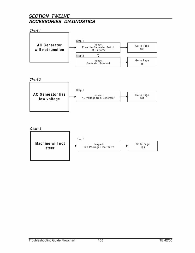
SECTION TWELVEACCESSORIES DIAGNOSTICS
Troubleshooting Guide Flowchart 165 TB 42/50
AC Generatorwill not function
Go to Page166
InspectPower to Generator Swi tch
at Plat form
Go to Page16
InspectGenerator Solenoid
AC Generator haslow voltage
Go to Page167
InspectAC Vol tage f rom Generator
OK
Step 1
Step 1
Step 2
Chart 1
Chart 2
Machine will notsteer
Go to Page168
InspectTow Package Float Valve
Step 1
Chart 3

SECTION TWELVEACCESSORIES DIAGNOSTICS
Troubleshooting Guide Flowchart 166 TB 42/50
AC Generatorwill notfunction
Step 1
Step 2
Repair or replaceGenerator Switch at
Platform
InspectPower to
Generator Switchat Platform
Using meter set to readvoltage, measure voltage
at wire #169 whenswitch is activated to
Generator posit ionShould read 10-12 volts
If no reading
Go to step 2
If10-12V
Repair or replaceWire from Platform
InspectGeneratorSolenoid
Using meter set to readvoltage, measure voltage
on Generator Solenoidwire #169
Should read 10-12 volts
If no reading
Repair or replaceSolenoid Valve
If10-12V

SECTION TWELVEACCESSORIES DIAGNOSTICS
Troubleshooting Guide Flowchart 167 TB 42/50
Step 1
AC Generatorhas lowvoltage
Adjust Speed ControlValve on Hydraulic
Generator Valvecounterclockwise to
increase voltage
InspectAC Voltage from
GeneratorUsing meter set to read
voltage, measure voltageat Generator
Should read 130 volts AC
If no reading

SECTION TWELVEACCESSORIES DIAGNOSTICS
Troubleshooting Guide Flowchart 168 TB 42/50
Step 1
Machine willnot steer
Check decal for correctposit ioning
InspectTow Package
Float ValveVisually inspect TowPackage Float Valveto insure valve is inoperational posit ion
No

