4 submersible pumps two and three wire … is supplied with a copper ground wire. splice this ground...
TRANSCRIPT

OWNERS MANUALINSTALLATION AND
OPERATING INSTRUCTIONS
4" SUBMERSIBLE PUMPSTwo and Three Wire
Single and Three Phase1/2 through 10 H.P.
60 Hz
Record the following information from the motor andpump nameplates for future reference:
Pump Model No.
Pump Serial No.
Motor Model No.
Motor Serial No.
H.P. Volts/Hz/Ph
Rated Amp Draw
©2006 PN280 (7/24/06)

Carefully read and follow all safety instructions inthis manual or on pump.
This is the safety-alert. When you see thissymbol on your pump or in this manual,
look for one of the following signal words and bealert to the potential for personal injury.
warns about hazards that will causeserious personal injury, death or major propertydamage if ignored.
warns about hazards that can causeserious personal injury, death or major propertydamage if ignored.
warns about hazards that will or cancause minor personal injury or property damage ifignored.The word NOTICE indicates special instructionswhich are important but not related to hazards.To avoid serious or fatal personal injury and possi-ble property damage, carefully read and follow thesafety instructions.
1. Hazardous pressure. Under cer-tain conditions, submersible pumps can developextremely high pressure. Install a pressure reliefvalve capable of passing entire pump flow at 75PSI (517 kPa) when using an air over water pres-sure tank. Install a pressure relief valve capableof passing entire pump flow at 100 PSI (690 kPa)when using a pre-charged pressure tank.
Do not allow pump, pressure tank, pip-ing, or any other system component
containing water to freeze. Freezing maydamage system, leading to injury or flooding.Allowing pump or system components tofreeze will void warranty.
2. Hazardous voltage. Can shock,burn or cause death. To avoid dangerous or fatalelectric shock hazard, use pump only in a waterwell.
Risk of dangerous or fatal electricalshock. Do not install this pump in any pond, river, orother open body of water that could be used forswimming or recreation. Do not swim, wade or playin a body of water in which a submersible pump hasbeen installed.
Installation must meet United StatesNational Electrical Code, Canadian
Electrical Code, and local codes (as applicable)for all wiring.
Disconnect electrical power supply beforeinstalling or servicing pump.
Make sure line voltage and frequency ofpower supply match motor nameplate volt-
age and frequency.
3. Install pump according to all plumbing, pumpand well code requirements.
4. Test well water for purity before using well. Call
your local health department for testing proce-dure.
5. During installation, keep well covered as muchas possible to prevent leaves and foreign matterfrom falling into well. Foreign objects in well cancontaminate the water and cause seriousmechanical damage to the pump.
6. Pipe joint compound can cause cracking in plas-tics. Use only teflon tape when sealing joints inplastic pipe or connecting pipe to thermoplasticpumps.
TABLE OF CONTENTS Safety Instructions . . . . . . . . . . . . . . . . . . . . . .2Pre-Installation . . . . . . . . . . . . . . . . . . . . . . . .2Electrical . . . . . . . . . . . . . . . . . . . . . . . . . .2-18PENTEK XE-Series . . . . . . . . . . . . . . . . . . . . . .4PENTEK T-Series . . . . . . . . . . . . . . . . . . . . . .5-6PENTEK 3-Phase . . . . . . . . . . . . . . . . . . . . . . .7Franklin . . . . . . . . . . . . . . . . . . . . . . . . . . .8-11Wiring . . . . . . . . . . . . . . . . . . . . . . . . . . .12-18Installation . . . . . . . . . . . . . . . . . . . . . . . .19-20Initial Startup . . . . . . . . . . . . . . . . . . . . . .20-21Effluent Applications . . . . . . . . . . . . . . . . . .21Connecting to Tank/Water System . . . . . .21-23Troubleshooting Guide . . . . . . . . . . . . . .24-25Warranty . . . . . . . . . . . . . . . . . . . . . . . . . . . .26
PRE-INSTALLATIONInspect pump and motor for delivery damage.Report any damage immediately to the shippingcarrier or to your dealer.The well driller should thoroughly develop the well(that is, pump out all fine sand and foreign matter)before pump is installed.Pump performance is based on pumping clear,cold, liquid water.Warranty is void in the following conditions:• If pump has pumped excessive sand – excessive
sand can cause premature wear to pump.• If water is corrosive.• If entrained gas or air are present in the water
being pumped – these can reduce flow andcause cavitation which can damage pump.
• If pump has been operated with discharge valveclosed – severe internal damage will result.
Install pump at least 15 to 20' (4.5 to 6M) belowthe lowest water level reached with pump running(lowest draw-down water level), and at least 5'(1.5M) above the bottom of the well.
WIRING/GROUNDING:Hazardous voltage. Can shock,
burn, or cause death. Permanently ground pump,motor and control box before connecting powersupply to motor.Ground pump and motor in accordance with thelocal codes and ordinances. Use a copper groundwire at least as large as wires carrying current tomotor.
2

Motor is supplied with a copper ground wire.Splice this ground wire to a copper conductorthat matches motor wire size specified in cable sizing charts,pages 5, 6, 10, and 11. SeePages 19 and 20 for cable splicing instructions.Permanently ground pump, motor and controlbox before connecting power cable to powersupply. Connect ground wire to approvedground first and then connect to equipmentbeing installed.Do not ground to a gas supply line.
Fire and electrical shock hazard. Ifusing a drop cable larger than No. 10 (5.5mm2)(for example, No. 8 (8.4mm2) wire) betweenpump and control box, run cable to a separatejunction box. Connect junction box to controlbox with a No. 10 (5.5mm2) or smaller wire(depending on amp rating of pump – see Table II,III, or IV).For more information, contact your local codeofficials.
WIRING CONNECTIONS:Installation must meet United States NationalElectrical Code, Canadian Electrical Code andlocal codes for all wiring (as applicable).Use only copper wire when making connectionsto pump and control box.To avoid over-heating wire and excessive voltagedrop at motor, be sure that wire size is at least aslarge as size listed in cable sizing charts for yourhorsepower pump and length of wire run.NOTICE: See Pages 14 through 18 for typicalwiring hookups and control box identification.NOTICE: When built-in overheating protectionis not provided, install an approved overloadequipped motor control that matches motorinput in full load amps. Select or adjust overloadelement(s) in accordance with control instruc-tions. When built-in overheating protection isprovided, use an approved motor control thatmatches motor input in full load amperes.
Rotation – (3 Phase only)To make sure motor is running in the right direc-tion, proceed carefully as follows:After electrical connections have been made asoutlined, and with pump hanging in well sup-ported from clamp on the discharge pipe, turnon then turn off the switch connecting the motorto the power supply line. Note rotation of pumpas motor starts. If connections are properlymade, pump will “jerk” clockwise when lookinginto the pump discharge when started. If “jerk”is counter-clockwise, the motor is running in the
wrong direction. Interchange any two cableleads where they connect to the “lead” terminalsin the magnetic starter. With connections proper-ly made, and pump lowered into water, turn onthe switch again and the pump should deliverwater according to the performance charts.
OVERLOAD PROTECTION OF THREEPHASE SUBMERSIBLE MOTORS – CLASS 10 PROTECTION REQUIREDThe characteristics of submersible motors aredifferent from standard motors and special over-load protection is required.If the motor is stalled, the overload must tripwithin 10 seconds to protect the motor wind-ings. The installer must use SUBTROL or thequick-trip protection shown in Tables VIII andIX. All recommended overload selections are ofthe ambient compensated type to maintain pro-tection at high and low air temperatures.All heaters and amp settings shown are based ontotal line amps. When a six-lead motor is usedwith a Wye-Delta starter, divide motor amps by1.732 to make your selection or adjustment forheaters carrying phase amps.Table VIII lists the correct selection and settingsof overloads for PENTEK T-Series motors. TableIX lists the same for Franklin motors. Approval ofother types may be requested from the motormanufacturer.NOTICE: Warranty on three phase submersiblemotors is void unless proper quick trip protec-tion in all three motor lines is used.
SURGE ARRESTERS IN CONTROL BOXGrounding: When the box has a surge arrester,the surge arrester MUST be grounded, metal tometal, all the way to the water strata for thearrester to be effective. Grounding the arresterto a driven ground rod provides little or no pro-tection for the motor.NOTICE: Surge arresters DO NOT protectagainst direct lightning strikes.Install grounded surge arresters to protect pumpfrom high voltage surges. Install arrester on theincoming power line to control box or pressureswitch, as close to pump motor as possible. SeeFigures 1 and 2 for installation wiring diagramsfor arresters.NOTICE: Ground the arrester with a No. 10 orlarger bare wire. Ground according to localcode requirements.NOTICE: If surge arresters wired into the controlbox are against local electrical code, contactpower company for correct wiring information.
3

4
Motor Winding Service Locked Fuze SizeVolts/ Resistance Factor Rotor Standard/
HP Hz/Ph Ohms Amps Amps Dual Element
1/2 115/60/1 1.4-1.7 9.5 36.4 30/20
1/2 230/60/1 4.6-5.6 4.7 19.5 15/10
3/4 230/60/1 3.5-4.3 6.4 24.8 20/15
TABLE II: Recommended Fusing Data - PENTEK XE-Series 60 Hz., Single Phase 2 WireSubmersible Pump Motors
NOTE: 2 Wire motor leads are not color coded. Overload islocated in motor and cannot be tested from above ground.
Motor Winding Service Locked Fuze SizeVolts/ Resistance-Ohms Factor Rotor Standard/
HP Hz/Ph R to Y B to Y Amps Amps Dual Element1/2 115/60/1 5.7-7.0 1.1-1.4 11.5 49.6 35/201/2 230/60/1 16.3-19.9 4.0-4.9 6.3 22.3 20/103/4 230/60/1 11.1-13.6 2.7-3.3 8.3 32.0 25/151 230/60/1 10.6-13.0 2.5-3.1 9.7 41.2 30/20
1-1/2 230/60/1 7.4-9.1 1.9-2.4 11.0 47.8 35/20
TABLE I: Recommended Fusing Data - PENTEK XE-Series 60 Hz., Single Phase, 3 WireInduction Run Submersible Pump Motors
XE-Series Motor SMC Submersible Motor Control TypeModel No. (3-W) HP Volts/Hz/Ph CSIR CSCRP43B0005A1 1/2 115/60/1 SMC-IR0511 –P43B0005A2 1/2 230/60/1 SMC-IR0521 SMC-CR0521P43B0007A2 3/4 230/60/1 SMC-IR0721 SMC-CR0721P43B0010A2 1 230/60/1 SMC-IR1021 SMC-CR1021P43B0015A2 1-1/2 230/60/1 – SMC-CR1521
PENTEK XE-Series Motor, Submersible Motor Control, and Fusing/Wiring Specifications.
TABLE IV: PENTEK Motor/Control Coordination
TABLE III: Copper Cable Length in Feet (Service to Motor)
Volts HP 14AWG 12AWG 10AWG 8AWG 6AWG 4AWG 3AWG 2AWG 1AWG
115V 1/2 99’ 157’ 250’ 398’ 633’ 1006’ 1269’ 1599’ 2016’
1/2 361 575 914 1453 2310 3673 4633 5839 7360
230V 3/4 274 436 694 1103 1753 2788 3517 4432 55871 235 373 593 944 1500 2385 3009 3793 4781
1-1/2 207 329 523 832 1323 2104 2653 3344 4216
PENTEK XE-Series Motors: 1 Ph, 3-Wire Cable, 60 Hz. Wire Size
Volts HP 14AWG 12AWG 10AWG 8AWG 6AWG 4AWG 3AWG 2AWG 1AWG
115V 1/2 120’ 191’ 303’ 482’ 766’ 1218’ 1536’ 1936’ 2441’
230V 1/2 485 770 1225 1947 3096 4923 6210 7827 98663/4 356 566 899 1430 2274 3615 4561 5748 7245
PENTEK XE-Series Motors: 1 Ph, 2-Wire Cable, 60 Hz. Wire Size
Volts HP KW 2.5 4 6 10 16 25 35 50 70
115V 1/2 .37 30m 48m 76m 121m 193m 307m 387m 488m 615m
1/2 .37 110 175 278 443 704 1119 1412 1780 2243
230V 3/4 .55 84 133 211 336 534 850 1072 1351 17031 .75 72 114 181 288 457 727 917 1156 1457
1-1/2 1.1 63 100 160 254 403 641 809 1019 1285
PENTEK XE-Series Motors: 1 Ph, 3-Wire Cable, 60 Hz. Wire Size in mm2
TABLE III-M: Copper Cable Length in Meters (Service to Motor)
Volts HP KW 2.5 4 6 10 16 25 35 50 70
115V 1/2 .37 37m 58m 92m 147m 233m 371m 468m 590m 744m
230V 1/2 .37 148 235 373 594 944 1501 1893 2386 30073/4 .55 108 172 274 436 693 1102 1390 1750 2208
PENTEK XE-Series Motors: 1 Ph, 2-Wire Cable, 60 Hz. Wire Size in mm2
NOTE: PENTEK XE- and T-Series Motors with model numbers beginning ‘P42’ or ‘P42T’ are 2-Wire motors anddo not use a Submersible Motor Control.

5
Motor Fuze SizeWinding Service Locked Standard/
Volts/ Resistance Factor Rotor Dual Element/HP Hz/Ph Ohms Amps Amps CB
1/2 115/60/1 1 11.0 38 35/20/30
1/2 230/60/1 4 5.5 19.0 20/10/15
3/4 230/60/1 2.47 7.4 25.0 25/15/20
1 230/60/1 1.87 8.9 38 30/20/25
TABLE VI: Recommended Fusing Data - PENTEK T-Series 60 Hz., Single Phase 2 WireSubmersible Pump Motors
NOTE: 2 Wire motor leads are not color coded. Overload islocated in motor and cannot be tested from above ground.
Fuze SizeMotor Winding Service Locked Standard/
Volts/ Resistance-Ohms Factor Rotor Dual Element/HP Hz/Ph Main Start Amps Amps CB
1/2 230/60/1 3.7 8.6 5.5 19 20/10/15
3/4 230/60/1 2.5 4.8 7.4 25 25/15/20
1 230/60/1 1.9 4.2 8.9 38 30/20/25
1-1/2 230/60/1 1.45 3.3 12.7 49 35/20/30
2 230/60/1 1.3 2.45 12.8 50 30/20/25
3 230/60/1 1.1 2.87 17.1 55 45/30/40
5 230/60/1 0.8 1.7 25.9 83 80/45/60
TABLE V: Recommended Fusing Data - PENTEK T-Series 60 Hz., Single Phase, 3 WireInduction Run Submersible Pump Motors
T-Series Motor SMCT Submersible Motor Control TypeModel No. (3-W) HP Volts/Hz/Ph CSCR CSCRPP43T0005A2 1/2 230/60/1 SMCT-CR0521 –P43T0007A2 3/4 230/60/1 SMCT-CR0721 –P43T0010A2 1 230/60/1 SMCT-CR1021 _P43T0015A2 1-1/2 230/60/1 SMCT-CR1521 _P43T0020A2 2 230/60/1 SMCT-CR2021 SMCT-CRP2021P43T0030A2 3 230/60/1 SMCT-CR3021 SMCT-CRP3021P43T0050A2 5 230/60/1 SMCT-CR5021 SMCT-CRP5021
NOTE: PENTEK XE- and T-Series Motors with model numbers beginning ‘P42’ or ‘P42T’ are 2-Wire motors anddo not use a Submersible Motor Control.
PENTEK T-Series Motor, Submersible Motor Control, and Fusing/Wiring Specifications.
TABLE VII: PENTEK T-Series Motor/Control Coordination
A Note on Nomenclature:
SSuubbmmeerrssiibbllee MMoottoorr CCoonnttrrooll:: The box,including the terminal strip(s), capacitor(s), relay(s), etc, which controlsthe basic on/off functions for a submersible motor.VVaarriiaabbllee SSppeeeedd DDrriivvee:: A programmablemotor control that varies pump speed tomaintain constant pressure under varying load conditions.
Submersible Motor Control Compatability
Motor Submersible Motor Control TypeType SMC Franklin SMCT
PENTEK XE-Series Yes Yes NOFranklin Yes Yes NOPENTEK T-Series NO NO Yes

6
Volts HP KW 2.5 4 6 10 16 25 35 50 70
115V 1/2 .37 31m 50m 79m 126m 214m 320m 404m 509m 642m
1/2 .37 126 200 319 507 806 1282 1617 2038 25713/4 .55 93 149 237 377 599 953 1202 1515 19111 .75 78 124 197 313 498 792 999 1260 1589
230V 1-1/2 1.1 54 86 138 219 349 555 700 883 11152 1.5 54 86 137 217 346 551 694 876 11053 2.2 40 64 102 163 259 412 520 655 8275 3.7 – – 67 107 171 272 343 432 546
PENTEK T-Series Motors: 1 Phase, 3- or 2- Wire Cable, 60 Hz. Wire Size in mm2
Volts HP KW 2.5 4 6 10 16 25 35 50 70
230V5 3.7 36 57 91 145 231 367 463 584 735
7-1/2 5.5 – – 67 107 170 271 342 431 544
3 2.2 231 367 584 929 1478 2350 2965 3737 4714
460V5 3.7 144 229 365 581 924 1469 1853 2335 2946
7-1/2 5.5 106 169 270 429 682 1085 1368 1725 217610 7.5 83 132 211 336 534 240 1071 1350 1704
PENTEK T-Series Motors: 3 Phase, 60 Hz. Wire Size in mm2
All cable lengths meet NEC for jacketed 60°C copper cable. Based on 3-Wire Induction Run requirements; Capacitor Runrequirements may vary. Local code requirements may vary. For aluminum cable, go up two sizes from chart (for example, ifthe chart calls for No. 10 AWG for copper, go to No. 8 AWG for aluminum; the smaller the number, the larger the cable).Use oxidation inhibitors on the connections.
Volts HP 14AWG 12AWG 10AWG 8AWG 6AWG 4AWG 3AWG 2AWG 1AWG
115V 1/2 104’ 165’ 262’ 416’ 662’ 1052’ 1327’ 1672’ 2109’
1/2 414 658 1047 1664 2646 4207 5307 6689 84383/4 308 489 778 1237 1967 3127 3944 4971 62711 256 407 647 1028 1635 2600 3280 4134 5214
230V 1-1/2 179 285 453 721 1146 1822 2298 2897 36542 178 283 450 715 1137 1808 2280 2874 36263 133 212 337 535 851 1353 1707 2151 27145 – – 222 353 562 893 1127 1420 1792
PENTEK T-Series Motors: 1 Phase, 3- or 2-Wire Cable, 60 Hz. Wire Size
Volts HP 14AWG 12AWG 10AWG 8AWG 6AWG 4AWG 3AWG 2AWG 1AWG
230 5 119 189 300 477 758 1205 1520 1916 24177-1/2 – – 221 352 560 890 1123 1415 1785
3 759 1207 1919 3051 4851 7713 9729 12263 15469
4605 474 754 1199 1907 3032 4821 6081 7664 9668
7.5 350 557 886 1408 2239 3560 4490 5660 714010 274 436 694 1103 1753 2788 3517 4432 5591
PENTEK T-Series Motors: 3 Phase, 60 Hz. Wire Size
All cable lengths meet NEC for jacketed 60°C copper cable. Based on 3-Wire Induction Run requirements; Capacitor Runrequirements may vary. Local code requirements may vary. For aluminum cable, go up two sizes from chart (for example, ifthe chart calls for No. 10 AWG for copper, go to No. 8 AWG for aluminum; the smaller the number, the larger the cable).Use oxidation inhibitors on the connections.
NOTESpecifications on pages 4 to 7 are for
PENTEK motors only. For Franklin specifications, see Pages 8 to 11.
TABLE VIII-M: Copper Cable Length in Meters (Service to Motor)
TABLE VIII: Copper Cable Length in Feet (Service to Motor)

7
NEMA Overload Heater Relays† Adjustable Relays
Motor PENTEK Starter Allen Set Max.Type Part Number HP kW Volts Size Bradley Furnas G.E. Amps Amps
P43T0030A4 3 2.2 460 0 J21 K37 L618A 5.6 6.0
P43T0050A3 5 3.7 230 1 J33 K61 L199B 20.0 22.0
4" P43T0050A4 5 3.7 460 0 J26 K49 L100B 8.9 9.6
3-Wire P43T0075A3 7-1/2 5.5 230 1 J37 K67 L293B 24.0 26.0
P43T0075A4 7-1/2 5.5 460 1 J30 K55 L147B 12.0 13.0
P43T0100A4 10 7.5 460 1 J33 K60 L199B 15.4 16.6
TABLE IX: PENTEK T-Series Three-Phase Motor OverloadProtection (60 Hz, 3450 RPM)
* Table data are generated per NEC and Heater Manufacturer Recommendations (see 2005 NEC-Chapter 3, Tables 430.52, 430.248,430.250, Allen Bradley, Siemens (Furnas) and G.E. catalogs for more information).
† Class 10 protection required. Warranty is void if Class 10 protection is not used.
PENTEK T-Series 3-Phase 4" MOTOROVERLOAD PROTECTION
PENTEK T-Series 3-phase submersible motorsmust have Class 10 overload protection that willdisconnect the power within 10 seconds in thecase of a locked rotor. To accomplish this, fixed-heater overloads are used. Refer to the chartbelow for appropriate heaters. The chart is basedupon total line amps.
Divide the motor amps by 1.732 when using a 6-lead motor with a Y-Delta Starter.
NOTICE: General Electric overload heaters areonly usable with General Electric overload relays.
Do not adjust relays to exceed nameplate amps.
For reliable 3-Phase starter operation, length ofwire between starter and service entrance shouldbe not more than 25% of total wire length.
Motor Winding Service Locked Fuze SizeVolts/ Resistance Factor Rotor Standard/
HP Hz/Ph Ohms Amps Amps Dual Element
3 460/60/3 5.72-4.68 6.0 40 15/10
5 230/60/3 0.90-0.73 22.0 132 50/30
5 460/60/3 3.70-3.02 9.6 66 25/15
7-1/2 230/60/3 0.62-0.50 26.0 180 80/45
7-1/2 460/60/3 2.60-2.10 13.0 90 40/25
10 460/60/3 2.20-1.80 16.6 110 60/30
TABLE X: Recommended Fusing Data - PENTEK T-Series 60 Hz., 3 Phase Submersible Pump Motors
NOTESpecifications on pages 4 to 7 are for
PENTEK motors only. For Franklin specifications, see Pages 8 to 11.
8
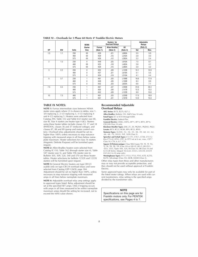
TABLE IX NOTES:NOTE 1: Furnas intermediate sizes between NEMAstarter sizes apply where (1) is shown in tables, size 1-3/4 replacing 2, 2-1/2 replacing 3, 3-1/2 replacing 4and 4-1/2 replacing 5. Heaters were selected fromCatalog 294, Table 332 and Table 632 (starter size 00,size B). Size 4 starters are heater type 4 (JG). Startersusing these heater tables include classes 14, 17 and 18(INNOVA), classes 36 and 37 (reduced voltage), andclasses 87, 88 and 89 (pump and motor control cen-ters). Overload relay adjustments should be set nohigher than 100% unless necessary to stop nuisancetripping with measured amps in all lines below name-plate maximum. Heater selections for class 16 starters(Magnetic Definite Purpose) will be furnished uponrequest.NOTE 2: Allen-Bradley heaters were selected fromCatalog IC-110, Table 162 (through starter size 4), Table547 (starter size 5), and Table 196 (starter size 6).Bulletin 505, 509, 520, 540 and 570 use these heatertables. Heater selections for bulletin 1232X and 1233Xstarters will be furnished upon request.NOTE 3: General Electric heaters are type CR123usable only on type CR124 overload relays and wereselected from Catalog GEP-126OJ, page 184.Adjustment should be set no higher than 100%, unlessnecessary to stop nuisance tripping with measuredamps in all lines below nameplate maximum.
NOTE 4: Adjustable overload relay amp settings applyto approved types listed. Relay adjustment should beset at the specified SET amps. Only if tripping occurswith amps in all lines measured to be within nameplatemaximum amps should the setting be increased, not toexceed the MAX value shown.
Recommended Adjustable Overload Relays
AEG Series: B17S, B27S, B27-2.Allen Bradley: Bulletin 193, SMP-Class 10 only.Fanal Types: K7 or K7D through K400.Franklin Electric: Subtrol-Plus.General Electric: CR4G, CR7G, RT*1, RT*2, RTF3, RT*4,CR324X-Class 10 only.Klockner-Moeller Types: Z00, Z1, Z4, PKZM1, PKZM3, PKZ2.Lovato: RC9, RC22, RC80, RF9, RF25, RF95.Siemens Types: 3UA50, -52, -54, -55, -58, -59, -60, -61, -62, -66, -68, -70, 3VUI3, 3VE, 3UB (Class 5).Sprecher and Schuh Types: CT, CT1, CTA 1, CT3K, CT3-12thru CT3-42, KTA3, CEF1 & CET3 set at 6 sec. max., CEP 7Class 10, CT4, 6, & 7, CT3.Square D/Telemecanique: Class 9065 types TD, TE, TF, TG,TJ, TK, TR, TJE, TJF (Class 10) or LR1-D, LR1-F, LR2-D13, -D23, -D33, Types 18A, 32A, SS-Class 10, SR-Class 10 and63-A-LB Series. Integral 18,32,63, GV2-L, GV2-M, GV2-P,GV3-M (1.6-10 amp only).Westinghouse Types: FT13, FT23, FT33, FT43, K7D, K27D,K67D, Advantage (Class 10), MOR, IQ500 (Class 5).
Other relay types from these and other manufacturersmay or may not provide acceptable protection, andthey should not be used without approval of FranklinElectric.Some approved types may only be available for part ofthe listed motor ratings. When relays are used with cur-rent transformers, relay setting is the specified ampsdivided by the transformer ratio.
Heaters for AdjustableNEMA Overload Relays RelaysStarter Furnas Allen Bradley GE (Note 4)
HP KW Volts Size (Note 1) (Note 2) (Note 3) Set Max.
1.5 1.1 230 00 K39 J21 L680A 5.5 5.9460 00 K29 J15 L343A 2.8 3.0575 00 K26 J12 L282A 2.2 2.4
2 1.5 230 0 K49 J25 L910A 7.5 8.1460 00 K33 J18 L463A 3.8 4.1575 00 K29 J15 L380A 3.0 3.2
3 2.2 230 0 K52 J28 L122B 10.1 10.9460 0 K37 J21 L618A 5.1 5.5575 0 K34 J19 L510A 4.1 4.4
5 3.7 230 1 K61 J33 L199B 16.6 17.8460 0 K49 J26 L100B 8.3 8.9575 0 K42 J23 L825A 6.6 7.1
7.5 5.5 230 1 K67 J37 L293B 24.6 26.4460 1 K55 J30 L147B 12.3 13.2575 1 K52 J28 L122B 9.9 10.6
10 7.5 460 1 K61 J33 L220B 17.5 18.8575 1 K57 J31 L181B 14.0 15.0
TABLE XI – Overloads for 3 Phase 60 Hertz 4" Franklin Electric Motors
NOTESpecifications on this page are forFranklin motors only. For PENTEKspecifications, see Pages 4 to 7.
9
ControlBox
L1 L2 R Y B
SurgeArrester
SurgeArrester
Line
L1 L2 L3
T1 T2 T3
3 Phase Surge Arrester(650 Volt Maximum)
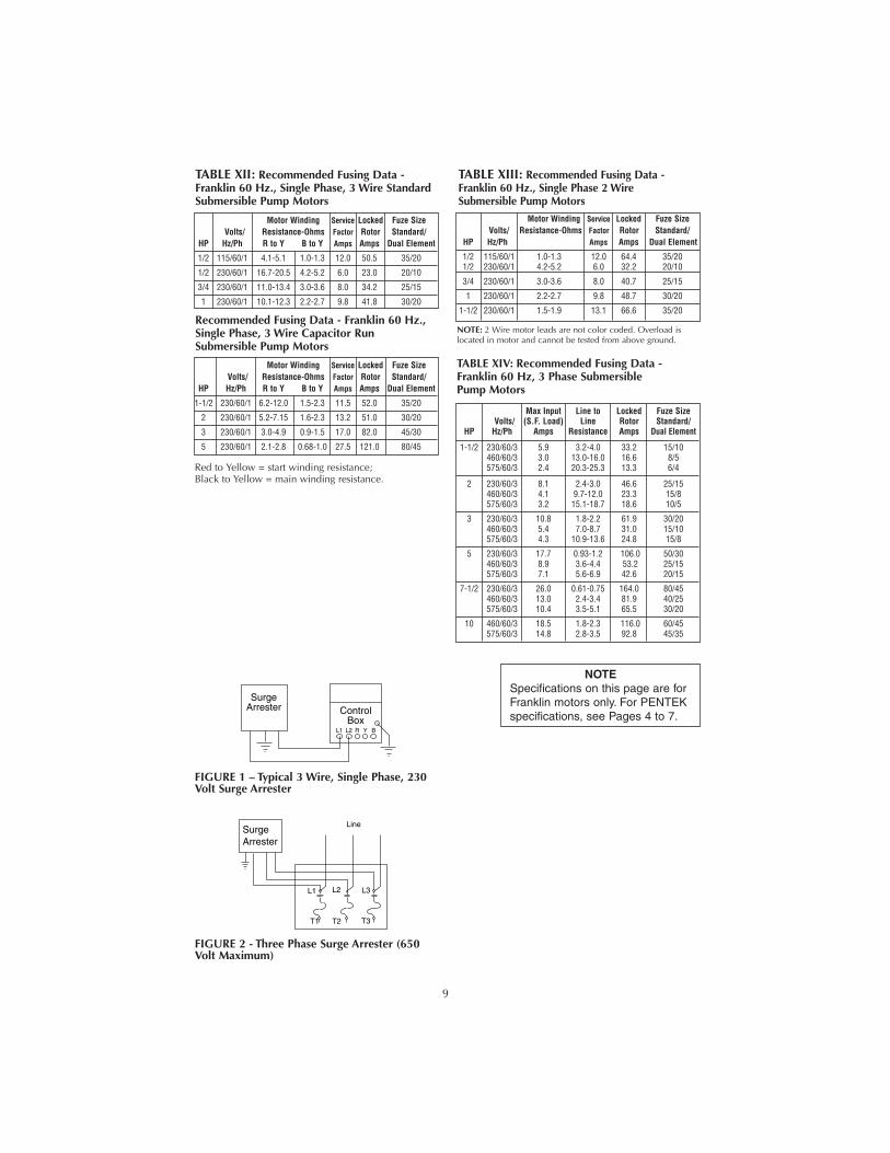
FIGURE 2 - Three Phase Surge Arrester (650Volt Maximum)
FIGURE 1 – Typical 3 Wire, Single Phase, 230Volt Surge Arrester
Max Input Line to Locked Fuze SizeVolts/ (S.F. Load) Line Rotor Standard/
HP Hz/Ph Amps Resistance Amps Dual Element
1-1/2 230/60/3 5.9 3.2-4.0 33.2 15/10460/60/3 3.0 13.0-16.0 16.6 8/5575/60/3 2.4 20.3-25.3 13.3 6/4
2 230/60/3 8.1 2.4-3.0 46.6 25/15460/60/3 4.1 9.7-12.0 23.3 15/8575/60/3 3.2 15.1-18.7 18.6 10/5
3 230/60/3 10.8 1.8-2.2 61.9 30/20460/60/3 5.4 7.0-8.7 31.0 15/10575/60/3 4.3 10.9-13.6 24.8 15/8
5 230/60/3 17.7 0.93-1.2 106.0 50/30460/60/3 8.9 3.6-4.4 53.2 25/15575/60/3 7.1 5.6-6.9 42.6 20/15
7-1/2 230/60/3 26.0 0.61-0.75 164.0 80/45460/60/3 13.0 2.4-3.4 81.9 40/25575/60/3 10.4 3.5-5.1 65.5 30/20
10 460/60/3 18.5 1.8-2.3 116.0 60/45575/60/3 14.8 2.8-3.5 92.8 45/35
TABLE XIV: Recommended Fusing Data -Franklin 60 Hz, 3 Phase SubmersiblePump Motors
Motor Winding Service Locked Fuze SizeVolts/ Resistance-Ohms Factor Rotor Standard/
HP Hz/Ph R to Y B to Y Amps Amps Dual Element
1/2 115/60/1 4.1-5.1 1.0-1.3 12.0 50.5 35/20
1/2 230/60/1 16.7-20.5 4.2-5.2 6.0 23.0 20/10
3/4 230/60/1 11.0-13.4 3.0-3.6 8.0 34.2 25/15
1 230/60/1 10.1-12.3 2.2-2.7 9.8 41.8 30/20
Motor Winding Service Locked Fuze SizeVolts/ Resistance-Ohms Factor Rotor Standard/
HP Hz/Ph R to Y B to Y Amps Amps Dual Element
1-1/2 230/60/1 6.2-12.0 1.5-2.3 11.5 52.0 35/20
2 230/60/1 5.2-7.15 1.6-2.3 13.2 51.0 30/20
3 230/60/1 3.0-4.9 0.9-1.5 17.0 82.0 45/30
5 230/60/1 2.1-2.8 0.68-1.0 27.5 121.0 80/45
Motor Winding Service Locked Fuze SizeVolts/ Resistance-Ohms Factor Rotor Standard/
HP Hz/Ph Amps Amps Dual Element
1/2 115/60/1 1.0-1.3 12.0 64.4 35/201/2 230/60/1 4.2-5.2 6.0 32.2 20/10
3/4 230/60/1 3.0-3.6 8.0 40.7 25/15
1 230/60/1 2.2-2.7 9.8 48.7 30/20
1-1/2 230/60/1 1.5-1.9 13.1 66.6 35/20
TABLE XII: Recommended Fusing Data -Franklin 60 Hz., Single Phase, 3 Wire StandardSubmersible Pump Motors
Recommended Fusing Data - Franklin 60 Hz.,Single Phase, 3 Wire Capacitor RunSubmersible Pump Motors
Red to Yellow = start winding resistance;Black to Yellow = main winding resistance.
TABLE XIII: Recommended Fusing Data -Franklin 60 Hz., Single Phase 2 WireSubmersible Pump Motors
NOTE: 2 Wire motor leads are not color coded. Overload islocated in motor and cannot be tested from above ground.
NOTESpecifications on this page are forFranklin motors only. For PENTEKspecifications, see Pages 4 to 7.

10
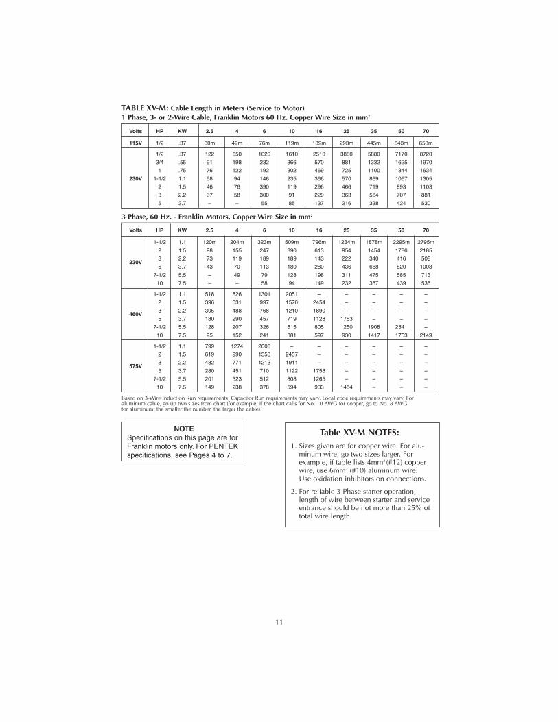
Volts HP 14 AWG 12 AWG 10 AWG 8 AWG 6 AWG 4 AWG 3 AWG 2 AWG 1 AWG 0 AWG
115V 1/2 100’ 160’ 250’ 390’ 620’ 960’ 1190’ 1460’ 1780’ 2160’
1/2 400 650 1020 1610 2510 3880 4810 5880 7170 8720
3/4 300 480 760 1200 1870 2890 3580 4370 5330 6470
1 250 400 630 990 1540 2380 2960 3610 4410 5360
230V 1-1/2 190 310 480 770 1200 1870 2320 2850 3500 4280
2 150 250 390 620 970 1530 1910 2360 2390 3620
3 120* 190 300 470 750 1190 1490 1850 2320 2890
5 – – 180 280 450 710 890 1110 1390 1740
TABLE XV: Cable Length in Feet (Service to Motor)1 Phase, 3- or 2-Wire Cable, Franklin Motors 60 Hz. Copper Wire Size AWG
Volts HP 14 AWG 12 AWG 10 AWG 8 AWG 6 AWG 4 AWG 3 AWG 2 AWG 1 AWG 0 AWG
1-1/2 420’ 670’ 1060’ 1670’ 2610’ 4050’ 5030’ 6160’ 7530’ 9170’
2 320 510 810 1280 2010 3130 3890 4770 5860 7170
230V3 240 390 620 990 1540 2400 2980 3660 4480 5470
5 140* 230 370 590 920 1430 1790 2190 2690 3290
7-1/2 – 160* 260 420 650 1020 1270 1560 1920 2340
10 – – 190* 310 490 760 950 1170 1440 1760
1-1/2 1700 2710 4270 6730 – – – – – –
2 1300 2070 3270 5150 8050 – – – – –
460V3 1000 1600 2520 3970 6200 – – – – –
5 590 950 1500 2360 3700 5750 – – – –
7-1/2 420 680 1070 1690 2640 4100 5100 6260 7680 –
10 310 500 790 1250 1960 3050 3800 4650 5750 7050
1-1/2 2620 4180 6580 – – – – – – –
2 2030 3250 5110 8060 – – – – – –
575V3 1580 2530 3980 6270 5750 – – – – –
5 920 1480 2330 3680 5750 – – – – –
7-1/2 660 1060 1680 2650 4150 – – – – –
10 490 780 1240 1950 3060 4770 5940 – – –
3 Phase, 60 Hz. - Franklin Motors, Copper Wire Size AWG
*Meets NEC for individual conductor 60°C cable. Only lengths without * meet NEC for jacketed 60°C cable. Local code requirements may vary.
Table XV NOTES:1. Sizes given are for copper wire. For alu-
minum wire, go two sizes larger. Forexample, if table lists #12 (3mm2) copperwire, use #10 (5mm2) aluminum wire.Use oxidation inhibitors on connections.
2. For reliable 3 Phase starter operation,length of wire between starter and serviceentrance should be not more than 25% oftotal wire length.
NOTESpecifications on this page are forFranklin motors only. For PENTEKspecifications, see Pages 4 to 7.
Motor ControlHP Voltage No. Box No.
1/2 115 214304 28010449214504
1/2 230 214305 28010549214505
3/4 230 214307 28010749214507
1 230 214308 28010849214508
1-1/2 230 224300 28230081
2 230 224301 2823018128230183
3 230 224302 2823028128230283
5 230 224303 2821138128211383
TABLE XVI: Franklin Control Box Selection
Submersible Motor Control Compatability
Motor Submersible Motor Control TypeType SMC Franklin SMCT
PENTEK XE-Series Yes Yes NOFranklin Yes Yes NOPENTEK T-Series NO NO Yes
11
NOTESpecifications on this page are forFranklin motors only. For PENTEKspecifications, see Pages 4 to 7.
Table XV-M NOTES:1. Sizes given are for copper wire. For alu-
minum wire, go two sizes larger. Forexample, if table lists 4mm2 (#12) copperwire, use 6mm2 (#10) aluminum wire.Use oxidation inhibitors on connections.
2. For reliable 3 Phase starter operation,length of wire between starter and serviceentrance should be not more than 25% oftotal wire length.
Volts HP KW 2.5 4 6 10 16 25 35 50 70
115V 1/2 .37 30m 49m 76m 119m 189m 293m 445m 543m 658m
1/2 .37 122 650 1020 1610 2510 3880 5880 7170 8720
3/4 .55 91 198 232 366 570 881 1332 1625 1970
1 .75 76 122 192 302 469 725 1100 1344 1634
230V 1-1/2 1.1 58 94 146 235 366 570 869 1067 1305
2 1.5 46 76 390 119 296 466 719 893 1103
3 2.2 37 58 300 91 229 363 564 707 881
5 3.7 – – 55 85 137 216 338 424 530
TABLE XV-M: Cable Length in Meters (Service to Motor)1 Phase, 3- or 2-Wire Cable, Franklin Motors 60 Hz. Copper Wire Size in mm2
Volts HP KW 2.5 4 6 10 16 25 35 50 70
1-1/2 1.1 120m 204m 323m 509m 796m 1234m 1878m 2295m 2795m
2 1.5 98 155 247 390 613 954 1454 1786 2185
230V3 2.2 73 119 189 189 143 222 340 416 508
5 3.7 43 70 113 180 280 436 668 820 1003
7-1/2 5.5 – 49 79 128 198 311 475 585 713
10 7.5 – – 58 94 149 232 357 439 536
1-1/2 1.1 518 826 1301 2051 – – – – –
2 1.5 396 631 997 1570 2454 – – – –
460V3 2.2 305 488 768 1210 1890 – – – –
5 3.7 180 290 457 719 1128 1753 – – –
7-1/2 5.5 128 207 326 515 805 1250 1908 2341 –
10 7.5 95 152 241 381 597 930 1417 1753 2149
1-1/2 1.1 799 1274 2006 – – – – – –
2 1.5 619 990 1558 2457 – – – – –
575V3 2.2 482 771 1213 1911 – – – – –
5 3.7 280 451 710 1122 1753 – – – –
7-1/2 5.5 201 323 512 808 1265 – – – –
10 7.5 149 238 378 594 933 1454 – – –
3 Phase, 60 Hz. - Franklin Motors, Copper Wire Size in mm2
Based on 3-Wire Induction Run requirements; Capacitor Run requirements may vary. Local code requirements may vary. Foraluminum cable, go up two sizes from chart (for example, if the chart calls for No. 10 AWG for copper, go to No. 8 AWGfor aluminum; the smaller the number, the larger the cable).
12
Calculating Cable size when two differentsizes can be used.Sometimes conditions make it desirable to usemore than one size cable in an installation. For example: Replace a pump with a 3 HP, 230 volt,60 Hz, single phase motor, with the motor setting at210' down the well and with 160' of #10 cableburied between the service entrance and the wellhead. In order to avoid replacing the buried cable,the question is: What size cable is required in thewell? Calculate as follows:1. According to Table VIII, a total of 280' of #10
cable is allowed to power the 3 HP motor. Theper cent of this total that has been used by the160' of cable in the buried run is: 160'/280' =.571 = 57.1%.
2. With 57.1% of the allowable cable already used,42.9% of the total length is left for use in thewell. To avoid running a cable that is too longand lowering the voltage to the motor, we haveto find a cable size large enough so that 210' isless than 42.9% of the total length allowed forthat size.
3. Trying #8 cable, Table VIII shows that the totalallowable length for a 3 HP motor is 443'. 443' x 42.9% = 443' x .429 = 190.0' This is not long enough.
4. Trying #6 cable, Table VIII shows that the totalallowable length is 689'. 689' x 42.9% = 689' x .429 = 295.6' This is longer than needed. Therefore, #6 cablecan be used for the 210' of cable in the well.Any combination of sizes can be used, providedthat the total percentage of the length of the twosizes of cable does not exceed 100% of theallowed lengths.
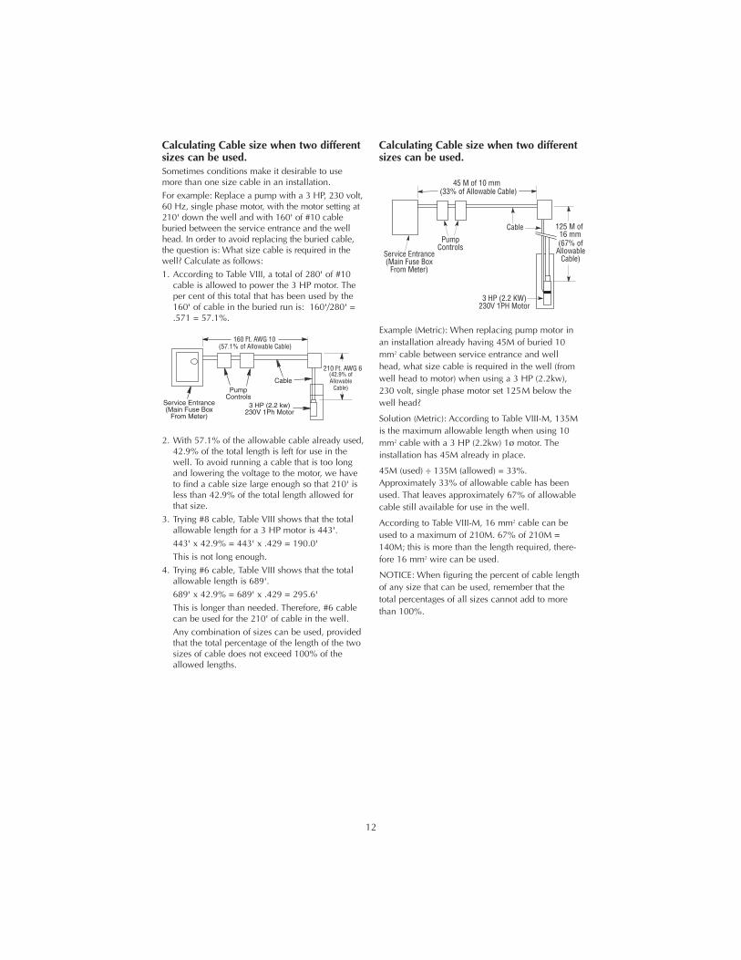
Calculating Cable size when two differentsizes can be used.
Example (Metric): When replacing pump motor inan installation already having 45M of buried 10mm2 cable between service entrance and wellhead, what size cable is required in the well (fromwell head to motor) when using a 3 HP (2.2kw),230 volt, single phase motor set 125M below thewell head?
Solution (Metric): According to Table VIII-M, 135Mis the maximum allowable length when using 10mm2 cable with a 3 HP (2.2kw) 1ø motor. Theinstallation has 45M already in place.
45M (used) ÷ 135M (allowed) = 33%.Approximately 33% of allowable cable has beenused. That leaves approximately 67% of allowablecable still available for use in the well.
According to Table VIII-M, 16 mm2 cable can beused to a maximum of 210M. 67% of 210M =140M; this is more than the length required, there-fore 16 mm2 wire can be used.
NOTICE: When figuring the percent of cable lengthof any size that can be used, remember that thetotal percentages of all sizes cannot add to morethan 100%.
CablePump
ControlsService Entrance(Main Fuse Box
From Meter)
3 HP (2.2 kw)230V 1Ph Motor
160 Ft. AWG 10
210 Ft. AWG 6
(57.1% of Allowable Cable)
(42.9% ofAllowable
Cable)
5411 0506
Cable
PumpControls
Service Entrance(Main Fuse Box
From Meter)
3 HP (2.2 KW)230V 1PH Motor
45 M of 10 mm
125 M of 16 mm
(33% of Allowable Cable)
(67% ofAllowable
Cable)

13
INSTALLATION WIRING DIAGRAMS -SINGLE PHASE, 3 WIRE
For motors of 1-1/2 HP and above,use magnetic starter to avoid damage to pressureswitch. Consult factory for wiring information.
Hazardous voltage. Can shock,burn, or kill.Ground control box, all metal plumbing, and motorframe with copper wire in compliance with localcodes. Use a ground wire at least as large as thewires supplying power to motor.Permanently close all unused openings in this andother equipment.Disconnect power to control box before workingon or around control box, pipes, cable, pump, ormotor.To be sure that starting relay will function and thatoverload will not “nuisance trip”, install controlbox vertically with top side up.Wire control box as shown on Pages 14 through18. Pump will not operate without control box, andsome boxes require a switch or a jumper leadbetween ‘SW’ and ‘L2’ terminals. Operation with-out control box will burn out motor.Installation must meet United States NationalElectrical Code, Canadian Electrical Code, andlocal codes for all wiring (as applicable).If main overload trips, look for:1. Shorted Capacitor
2. Voltage Problems3. Overloaded or locked pump.NOTICE: Match motor to control box or sub-mersible motor control as shown on pages 4, 5 and10. Franklin motor and control box model numbersmay include additional suffix numbers to the rightof the numbers shown here. These additional num-bers are not important for control box selection.
LIQUID LEVEL (PUMP DOWN)CONTROLS:Use pump down controls on wells with low flowto prevent pumping well dry. See Wiring dia-grams, Pages 14 through 18, for proper installa-tion.NOTICE: Ground controls according to localcode requirements.
If start overload trips, replace start relay. Reset andanalyze for tripping cause. To avoid motor burnout,do not remove or short circuit overload protection.

14
Installation Wiring Diagrams – Single Phase, 3 WireFor motors of 1-1/2 HP and above, use magnetic starter to avoid damage to pressure
switch. Consult factory for wiring information.
SINGLE PHASE - 1/2 HP THRU 5 HP STANDARDCONTROL BOX WITH ADEQUATE RATED
PRESSURE SWITCH
L1 M1
M2L2
CONTROLBOX
L1 L2 R Y B
FusedDisconnect
Switch
To Line Ground
RedYellowBlack
PressureSwitch
WellCasing
Ground
355 0893
SINGLE PHASE - 1/2 HP THRU 5 HP STANDARDCONTROL BOX WITH PRESSURE SWITCH (One pump
for 2 houses) With adequate rated pressure switch
CONTROLBOX
L1 L2 R Y B
RedYellow
Black
WellCasing Ground
GroundTo LineTo Line
L1 M1
M2L2L1 M1
M2L2
FusedDisconnect
Switch
PressureSwitch
PressureSwitch
Aux. Relayor Equivalent
359 0893
Follow color coding when connecting control box (Yellow to Y, Red to R, Black to B).
CHECKING PROCEDURE (ALL BOXES):
Hazardous voltage. Can shock,burn, or cause death. Disconnect power to con-trol box before doing these check procedures.
A. General Procedures. (Power to control boxdisconnected)1. Disconnect line.2. Inspect for damaged or burned parts, loose
connections, etc.3. Check for misconnections against diagram
in control box.4. If box is too hot, circuit breakers may trip
or fuses blow. Ventilate or shade box.Move away from heat source.
5. If problem has not been found, checkmotor and control box. Use test proce-dures that follow.
B. Ground (Insulation Resistance) Test. (Powerto control box disconnected)1. Ohmmeter Setting: Highest scale (usually
Rx100K or Rx10,000).2. Terminal Connections: One ohmmeter lead
to “Ground” screw on control box andtouch other lead to each of the terminalson terminal board.
3. Ohmmeter Reading: Pointer should remainat infinity (∞) and not deflect.
C. Capacitor Tests. (Power to control box dis-connected)
Risk of electric shock. Shortcapacitor across terminals before testing.
1. Ohmmeter Setting: Rx1000.2. Terminal Connections: Connect ohmmeter
leads to black and orange wires out ofcapacitor case.
3. Ohmmeter Reading: Pointer should swingtoward “zero” and “float” back to (∞).Capacitor is shorted if pointer does notmove back to (∞), open if it does not movefrom (∞).
4. To reset capacitor, reverse ohmmeter con-nection to capacitor terminals.
D.Triac Test. (Solid state switch only)1. Ohmmeter Setting: Rx1000.2. Connect the leads to “R” (start) terminal
and to orange lead terminal on startswitch.
3. Ohmmeter reading: Infinity (∞).
E. Coil Test. (Solid state switch only)1. Ohmmeter Setting: Rx1. 2. Connect leads to “Y” (common) and L2 ter-
minal and to orange lead terminal on startswitch.
3. Ohmmeter reading: Infinity (∞).

15
Installation Wiring Diagrams – Single Phase, 3 WireFor motors of 1-1/2 HP and above, use magnetic starter to avoid damage to pressure
switch. Consult factory for wiring information.
SINGLE PHASE - 1/2 HP THRU 5 HP STANDARDCONTROL BOX WITH LIQUID LEVEL CONTROL
SINGLE PHASE - 1/2 HP THRU 5 HP STANDARDCONTROL BOX WITH PRESSURE SWITCH &
LIQUID LEVEL CONTROL
Black
RedYellow
WellCasing
Ground
ControlBox
L1 L2 R Y B
FusedDisconnect
Switch
To LineGround
6
7
1
2
5
8
9
HighElectrode
LowElectrode
LiquidLevel
Control
353 0893
Red
YellowBlack
WellCasing
Ground
ControlBox
L1 L2 Y B R
FusedDisconnect
Switch
To LineGround
1
2
5
8
9 6
7
HighElectrode
LowElectrode
BW LiquidLevel Control
L1 M1
L2 M2
PressureSwitch
1271 0994
Follow color coding when connecting control box (Yellow to Y, Red to R, Black to B).
OPEN SYSTEM-SINGLE PHASE - 1/2 HP THRU 5 HPSTANDARD CONTROL BOX
SINGLE PHASE - 2, 3 & 5 HP DELUXE CONTROLBOXES WITH PRESSURE SWITCH
ControlBox
L1 L2 R Y B
FusedDisconnect
Switch
To LineGround
RedYellowBlack
WellCasing
Ground
357 0893
Red
YellowBlack
WellCasing
Ground
ControlBox
L1 L2 Y B R
FusedDisconnect
Switch
To LineGround
SW
L1 M1
L2 M2PressureSwitch
3108 1197

16
Installation Wiring Diagrams – Single Phase, 3 WireFor motors of 1-1/2 HP and above, use magnetic starter to avoid damage to pressure
switch. Consult factory for wiring information.
SINGLE PHASE - 1/2 HP THRU 5 HP STANDARDCONTROL BOX WITH LIQUID LEVEL CONTROL
SINGLE PHASE - 1/2 HP THRU 5 HP STANDARDCONTROL BOX WITH PRESSURE SWITCH &
LIQUID LEVEL CONTROL
Follow color coding when connecting control box (Yellow to Y, Red to R, Black to B).
Red
YellowBlack
WellCasing
Ground
ControlBox
L1 L2 Y B R
FusedDisconnect
Switch
To LineGround
1
2
5
8
9
6
7
HighElectrode
LowElectrode
SWBW Liquid
Level Control
354 0893
Red
YellowBlack
WellCasing
Ground
ControlBox
L1 L2 Y B R
FusedDisconnect
Switch
To LineGround
1
2
5
8
9 6
7
HighElectrode
LowElectrode
SW
BW LiquidLevel Control
L1 M1
L2 M2
PressureSwitch
358 0893
OPEN SYSTEM-SINGLE PHASE - 1/2 HP THRU 5 HPSTANDARD CONTROL BOX
Red
YellowBlack
WellCasing
Ground
ControlBox
L1 L2 Y B R
FusedDisconnect
Switch
To LineGround
SW
1270 0994

17
Installation Wiring Diagrams – Three Phase
THREE PHASE - 1-1/2 HP & LARGERWITH PRESSURE SWITCH
THREE PHASE - 1-1/2 HP & LARGERWITH PRESSURE SWITCH &LIQUID LEVEL CONTROL
FusedDisconnectSwitch
WellCasing
LM
M L
MagneticStarter
PressureSwitch
L 1 L 2 L 3
T 1 T 2 T 3
362 0893
FusedDisconnect
Switch
WellCasing
LM
M L
MagneticStarter
PressureSwitch
1
2
5
8
9 6
7
L 1 L 2 L 3
T 1 T 2 T 3LiquidLevelControl
High Electrode
LowElectrode
361 0893
Follow color coding when connecting control box (Yellow to Y, Red to R, Black to B).

18
Installation Wiring Diagrams – 2 WireFor motors of 1-1/2 HP and above, use magnetic starter to avoid damage to pressure
switch. Consult factory for wiring information.
WITH PRESSURE SWITCHAND LIQUID LEVEL CONTROL
ONE PUMP FOR TWO HOUSESWITH PRESSURE SWITCH
Follow color coding when connecting control box (Yellow to Y, Red to R, Black to B).
WellCasing
Ground
FusedDisconnect
Switch
To LineGround
1
2
5
8
9 6
7
HighElectrode
LowElectrode
BW LiquidLevel Control
L1 M1
L2 M2
PressureSwitch
363 0994
WellCasing
Ground
LineLine
L1M1 M2
L2 L1M1 M2
L2
FusedDisconnect
Switch
PressureSwitch
Aux. Relayor Equivalent
House No. 1 House No. 2
3109 1197ONE PUMP FOR ONE HOUSE
WITH PRESSURE SWITCH
L1 M1
M2L2
FusedDisconnect
Switch
To Line Ground
Red
Black
PressureSwitch
WellCasing
Ground(Green)
360 0893
19
1"2
1"2
INSULATOR BODYCENTERED OVER SPLICE
END CAP
GASKET
INSULATOR BODY
GASKET SLEEVE IN PLACECAP SCREWED ON
BUTT CONNECTOR ORCRIMP OR SOLDER
12.7mm 12.7mm
FIGURE 10
FIGURE 11
FIGURE 12
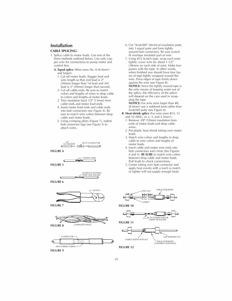
InstallationCABLE SPLICING:1. Splice cable to motor leads. Use one of the
three methods outlined below. Use only cop-per wire for connections to pump motor andcontrol box.A. Taped splice (Wire sizes No. 8 (8.4mm2)
and larger):1. Cut off motor leads. Stagger lead and
wire length so that 2nd lead is 2"(50mm) longer than 1st lead and 3rdlead is 2" (50mm) longer than second.
2. Cut off cable ends. Be sure to matchcolors and lengths of wires in drop cableto colors and lengths of motor leads.
3. Trim insulation back 1/2" (13mm) fromcable ends and motor lead ends.
4. Insert motor lead ends and cable endsinto butt connectors (see Figure 4). Besure to match wire colors between dropcable and motor leads.
5. Using crimping pliers (Figure 7), indentbutt connector lugs (see Figure 5) toattach wires.
6. Cut “Scotchfil” electrical insulation puttyinto 3 equal parts and form tightlyaround butt connectors. Be sure scotch-fil overlaps insulated part of wire.
7. Using #33 Scotch tape, wrap each jointtightly; cover wire for about 1-1/2"(38mm) on each side of joint. Make fourpasses with the tape. In other words,when finished you should have four lay-ers of tape tightly wrapped around thewire. Press edges of tape firmly downagainst the wire (see Figure 8).NOTICE: Since the tightly wound tape isthe only means of keeping water out ofthe splice, the efficiency of the splicewill depend on the care used in wrap-ping the tape.NOTICE: For wire sizes larger than #8,(8.4mm2) use a soldered joint rather thanScotchfil putty (see Figure 6).
B. Heat-shrink splice (For wire sizes #14, 12and 10 AWG, or 2, 3, and 5.5mm2):1. Remove 3/8" (10mm) insulation from
ends of motor leads and drop cablewires.
2. Put plastic heat shrink tubing over motorleads.
3. Match wire colors and lengths in dropcable to wire colors and lengths ofmotor leads.
4. Insert cable and motor wire ends intobutt connectors and crimp (See Figures4 and 5). BE SURE to match wire colorsbetween drop cable and motor leads.Pull leads to check connections.
5. Center tubing over butt connector andapply heat evenly with a torch (a matchor lighter will not supply enough heat).
COMPLETED SPLICE
1/2"(12.7mm) BUTT CONNECTOR
INDENT HERE
ALTERNATE METHODTWIST AND SOLDER
NOTCH
CONNECTOR
HEAT SHRINK TUBING
FIGURE 4
FIGURE 5
FIGURE 6
FIGURE 7
FIGURE 8
FIGURE 9
20
NOTICE: Keep torch moving. Too muchconcentrated heat may damage tubing(see Figure 9).
C. Butt Connectors with plastic insulators (for14, 12 and 10 Gauge AWG Wire, or 2, 3and 5.5mm2 wire):1. Cut off motor leads. Stagger lead and
wire length so that 2nd lead is 4"(100mm) longer than 1st lead and 3rdlead is 4" (100mm) longer than second.
2. Cut off cable ends. Be sure to matchcolors and lengths of wires in drop cableto colors and lengths of motor leads.
3. Trim insulation back 1/2" (13mm) fromcable ends and motor lead ends.
4. Unscrew plastic caps from insulators.Place a cap and a neoprene gasketsleeve on each wire end to be spliced(see Figure 10).
5. Slide insulator body onto one wire end(Figure 10).
6. Insert wire end into butt connector andcrimp (see Figure 11). Be sure to matchcable and motor wire colors.
7. Center insulator body over splice andslide neoprene sleeves into body as faras they will go. Screw caps onto insula-tor body (Figure 12) and tighten by handfor a strong, waterproof splice.
CABLE INSTALLATION1. To test submersible, momentarily connect it
to proper power supply. Power supply fre-quency and voltage must match motor name-plate frequency and voltage to within ±10%.(3 Phase pumps – see “Rotation,” Page 3).
2. Fasten cable leads securely to pump dis-charge section; leave 4-5" (100-127mm) ofslack in leads at this point. Securely fastenleads to plastic pipe within 6" (150mm) of thepump discharge section. Use torque arrestersto protect pump and pipe from twisting dam-age as pump starts and stops.
3. Connect copper ground wire to motor brack-et. Ground wire must be at least as large aswires supplying current to motor. Consult cur-rent National Electrical Code, CanadianElectrical Code and local codes (as applica-ble) for grounding information.
4. Use only submersible cable supplied by pumpmanufacturer. When lowering pump into well,secure cable to discharge pipe at 10' (3.5M)intervals with Scotch #33 electrical tape. Takecare not to damage pump cable.NOTICE: To avoid dropping the pump downthe well or damaging cable or cable splices,NEVER allow pump cable to support weightof pump.
PUMP INSTALLATION1. If a standard air over water pressure tank is
being used, install two bleeder orifices about2' (.6M) apart as shown in Figure 15, Page21. These orifices will automatically chargethe tank with air. See Figure 15 to determineorifice location.NOTICE: If Pre-charged tank is used, DONOT install bleeder orifices. If pump and pre-charged tank are replacing a standard tanksystem, remove bleeder orifices beforeinstalling pump in well.
2. To prevent losing pump down the well, con-nect a safety rope strong enough to supportpump and drop pipe (minimum 5/16" (8mm)twisted polypropylene or pronila rope) to eye-let on pump discharge. Tie off other end ofsafety rope securely to well seal, well cap orpitless adapter.
3. Discharge outlet is threaded 2” NPT (60 Hz)or 2” BSP (50 Hz).Use 100 PSI rated polyethylene plastic pipefor installations up to 100’ depth.Use 160 PSI rated polyethylene plastic pipefor installation up to 220’ depth.For depths beyond 220’, use galvanized steelpipe for the entire drop pipe.
INITIAL START-UPNOTICE: NEVER operate pump with dischargevalve completely closed. Pump can destroy itselfif run with discharge shut off (“deadheaded”) andwarranty will be void.NOTICE: To avoid sand-locking pump, followprocedure below when starting pump for thefirst time. NEVER start a pump with dischargecompletely open unless you have done this pro-cedure first.1. Connect a pipe elbow, a short length of pipe
and a gate valve to pump discharge at wellhead (see Figure 13).
2. Mount motor control box (3-wire pump),fused disconnect switch (2-wire pump), ormagnetic starter (3-phase pump) in a perma-nently weather proofed place. Make sure thatcontrols will not be subjected to extreme heator excess moisture.
3. Make sure controls are in OFF position.4. Connect motor leads and power supply to
motor control box, fused disconnect switch, ormagnetic starter (see Wiring Diagrams, Pages14 through 18). DO NOT START PUMP YET.
5. Set gate valve on discharge 1/3 open; startpump (see Figure 13).
6. Keep gate valve at this setting while waterpumps out on ground. Let it run until water isclear of sand or silt. (To check solids in water,fill a glass from pump and let solids settle out).

21
7. When water is completely clear at 1/3 set-ting, open gate valve to approximately two-thirds open and repeat process.
8. When water is completely clear at 2/3 set-ting, open gate valve completely and runpump until water is completely clear.
9. Remove gate valve for permanent installationnear tank (see Figures 14 and 15, Pages 22and 23).
10. Install sanitary well seal or pitless adapterunit, well unit, electrical conduit and surfacepiping according to local code requirements.
EFFLUENT APPLICATIONSPumps designed and tested for effluent applica-tions must meet the following:
Risk of electric shock. Do notremove cord and strain relief. Do not connectconduit to pump.1. Only qualified personnel should install the
pump and associated control equipment.2. Vent sewage or septic tank according to local
codes.3. Do not install pump in any location classified
as hazardous by National Electrical Code,ANSI/NFPA 70-1984.
4. These pumps are intended for permanentconnection only. Provide strain relief at con-trol box for power supply cord connection tobox. All control components must be UL list-ed and suitable for end use application.
CONNECTING TO TANK/WATER SYSTEMHazardous pressure. Submersible
pumps can develop very high pressure in somesituations. To prevent tank blowup, install apressure relief valve able to pass full pump flowat 75 PSI (517 kPa) when using an air overwater pressure tank. Install a pressure reliefvalve capable of passing entire pump flow at100 PSI (690 kPa) when using a pre-chargedpressure tank. Install this relief valve betweenpump and tank.NOTICE: Allowing pump or piping system tofreeze may severely damage pump and will voidwarranty. Protect pump and entire piping system(including pressure tank) from freezing.
Standard Tank Hookup:See Figure 15, Page 23 for piping connectionsto standard pressure tank and for correct dis-tance of bleeder orifices from pressure tank.
Pre-charged Pressure Tank Hookup:See Figure 14, Page 22 for piping connectionsto pre-charged pressure tank.NOTICE: Check air pre-charge in tank beforestarting pump. Adjust pre-charge to 2 PSI (13.8kPa) below pump cut-in setting. (For example, a
pre-charge tank used with a 30-50 switchshould be pre-charged with air to 28 PSI (193kPa) . Adjust pre-charge by either adding orbleeding air through tire valve located on top oftank. Check pre-charge annually and adjust asneeded.
Important Electrical Grounding Information
Hazardous voltage. Can shock,burn, or kill. To reduce the risk of electricalshock during pump operation, ground andbond the pump and motor as follows:A. To reduce risk of electrical shock from metal
parts of the assembly other than the pump,bond together all metal parts accessible at thewell head (including metal discharge pipe,metal well casing, and the like). Use a metalbonding conductor at least as large as thepower cable conductors running down the wellto the pump's motor.
B. Clamp or weld (or both if necessary) thisbonding conductor to the grounding meansprovided with the pump, which will be theequipment-grounding terminal, the groundingconductor on the pump housing, or an equip-ment-grounding lead. The equipment-ground-ing lead, when provided, will be the conductorhaving green insulation; it may also have oneor more yellow stripes.
C. Ground the pump, motor, and any metallicconduit that carries power cable conductors.Ground these back to the service by connect-ing a copper conductor from the pump, motor,and conduit to the grounding screw providedwithin the supply-connection box wiring com-partment. This conductor must be at least aslarge as the circuit conductors supplying thepump
Save these instructions.
Controlcenter
orelectrical
disconnectbox
Temporary wiringto control center or
electrical disconnect boxTemporary piping
Gate valve
Pump in wellPump installationfor developing a well
689 0993
FIGURE 13

22
VEN
TILA
TED
WEL
L C
AP
SUB
MER
SIB
LEC
AB
LE
PITL
ESS
AD
APT
OR
CH
ECK
VA
LVE
TAPE
CA
BLE
TO P
IPE
PUM
P
CO
NTR
OL
BO
X(3
WIR
E M
OD
ELS)
ELEC
TRIC
AL
DIS
CO
NN
ECT PR
E-C
HA
RG
ED T
AN
K
PRES
SUR
E SW
ITC
H
PRES
SUR
E G
AU
GE
TO H
OU
SE S
ERV
ICE
REL
IEF
VA
LVE
UN
ION
GA
TE V
ALV
E
FIG
UR
E 14
– T
ypic
al S
ubm
ersi
ble
Inst
alla
tion
wit
h Pr
e-ch
arge
d Ta
nk
Cut
-In
PSI
Cut
-Off
PSI
Pre-
char
ge P
ress
ure
20 (1
38 k
Pa)
40 (2
76 k
Pa)
18 P
SI (1
24 k
Pa)
30 (2
07 k
Pa)
50 (3
45 k
Pa)
28 P
SI (1
93 k
Pa)
40 (2
76 k
Pa)
60 (4
14 k
Pa)
38 P
SI (2
62 k
Pa)

23
PITL
ESS
AD
APT
OR
CH
ECK
VA
LVE
BLE
EDER
O
RIF
ICE
& T
EE
PIPE
CO
UPL
ING
TAPE
CA
BLE
TO P
IPE PU
MP
VEN
TILA
TED
WEL
L C
AP
SUB
MER
SIB
LEC
AB
LE
UN
ION
CO
NTR
OL
BO
X(3
WIR
E M
OD
ELS)
ELEC
TRIC
AL
DIS
CO
NN
ECT PR
ESSU
RE
GA
UG
E
AIR
VO
LUM
E C
ON
TRO
L
PRES
SUR
E SW
ITC
H
TO H
OU
SE S
ERV
ICE
GA
TE V
ALV
E
REL
IEF
VA
LVE
2 ft.
(.6m
)
SEE
TAB
LE
FIG
UR
E 15
– S
tand
ard
Pres
sure
Tan
k In
stal
lati
on
CH
ECK
VA
LVE
DIS
TAN
CE
TO T
OP
BLE
EDER
OR
IFIC
ETA
NK
SIZ
ED
ISTA
NC
E
42 G
allo
n (1
59L)
2' (.
6M)
82 G
allo
n (3
10L)
3' (.
9M)
120
Gal
lon
(454
L)5'
(1.4
M)
220
Gal
lon
(833
L)5'
(1.4
M)
315
Gal
lon
(119
2L)
10' (
3.0M
)
525
Gal
lon
(198
7L)
15' (
4.6M
)
24
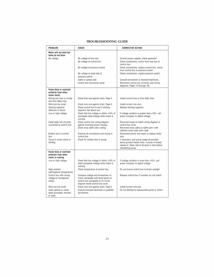
PROBLEM CHECK CORRECTIVE ACTION
Motor will not start butfuses do not blowNo voltage No voltage at fuse box. Consult power supplier, check generator.
No voltage at control box. Check connections, rewire from fuse box to control box.
No voltage at pressure switch Check connections, replace control box, rewirefrom control box to pressure switch.
No voltage on load side of Check connections, replace pressure switch.pressure switch.Cable or splices bad. Consult serviceman or licensed electrician.Control box incorrectly wired. Reconnect control box correctly (see wiring
diagrams, Pages 14 through 18).
Fuses blow or overloadprotector trips whenmotor startsWrong size fuse or wrong Check fuse size against chart, Page 4. Install correct fuse or time delay fuse.size time delay fuse.Wire size too small Check wire size against chart, Page 5. Install correct size wire.Starting capacitor Check control box to see if starting Replace starting capacitor.defective or blown. capacitor has blown out.Low or high voltage Check that line voltage is within ±10% of If voltage variation is greater than ±10%, call
nameplate rated voltage while motor is power company to adjust voltage.running.
Cable leads not correctly Check control box wiring diagram Reconnect leads to match wiring diagram in connected to control box. against incoming power hookup. control box cover.
Check drop cable color coding. Reconnect drop cable so cable color codematches motor lead color code.
Broken wire in control Examine all connections and wiring in Disconnect power and repair or replace faultybox. control box. wire.Pump or motor stuck or Check for locked rotor in pump. If necessary, pull pump (make all possiblebinding. above ground checks first). If pump is locked,
replace it. Clean well of all sand or lime beforereinstalling pump.
Fuses blow or overloadprotector trips whenmotor is runningLow or high voltage. Check that line voltage is within ±10% of If voltage variation is more than ±10%, call
rated nameplate voltage while motor is power company to adjust voltage.running.
High ambient Check temperature of control box. Do not mount control box in direct sunlight.(atmospheric temperature)Control box with wrong Compare voltage and horsepower on Replace control box if numbers do not match.voltage or horsepower motor nameplate with those given onrating. control box nameplate or on circuit
diagram inside control box cover.Wire size too small Check wire size against chart, Page 5. Install correct wire size.Cable splices or motor Consult licensed electrician or qualified Do not attempt to disassemble pump or motor.leads grounded, shorted, serviceman.or open.
TROUBLESHOOTING GUIDE
25
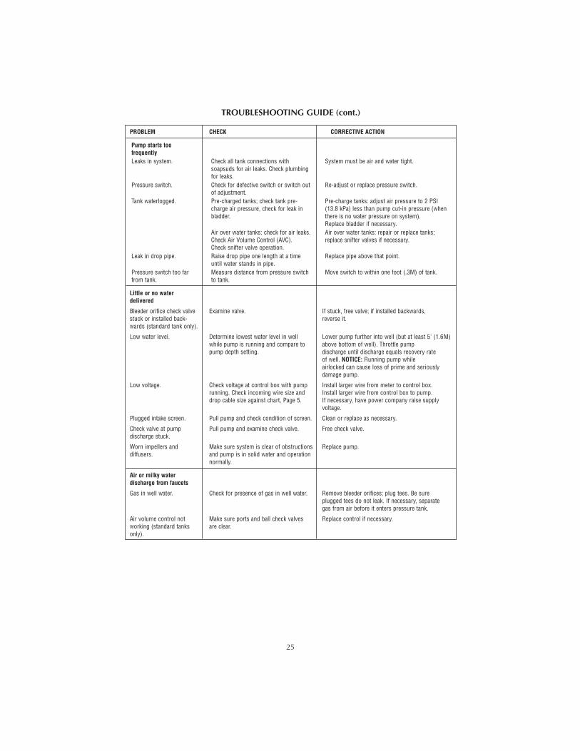
PROBLEM CHECK CORRECTIVE ACTION
Pump starts toofrequentlyLeaks in system. Check all tank connections with System must be air and water tight.
soapsuds for air leaks. Check plumbingfor leaks.
Pressure switch. Check for defective switch or switch out Re-adjust or replace pressure switch.of adjustment.
Tank waterlogged. Pre-charged tanks; check tank pre- Pre-charge tanks: adjust air pressure to 2 PSI charge air pressure, check for leak in (13.8 kPa) less than pump cut-in pressure (when bladder. there is no water pressure on system).
Replace bladder if necessary.Air over water tanks: check for air leaks. Air over water tanks: repair or replace tanks;Check Air Volume Control (AVC). replace snifter valves if necessary.Check snifter valve operation.
Leak in drop pipe. Raise drop pipe one length at a time Replace pipe above that point.until water stands in pipe.
Pressure switch too far Measure distance from pressure switch Move switch to within one foot (.3M) of tank.from tank. to tank.
Little or no waterdelivered
Bleeder orifice check valve Examine valve. If stuck, free valve; if installed backwards, stuck or installed back- reverse it.wards (standard tank only).
Low water level. Determine lowest water level in well Lower pump further into well (but at least 5' (1.6M)while pump is running and compare to above bottom of well). Throttle pumppump depth setting. discharge until discharge equals recovery rate
of well. NOTICE: Running pump whileairlocked can cause loss of prime and seriouslydamage pump.
Low voltage. Check voltage at control box with pump Install larger wire from meter to control box.running. Check incoming wire size and Install larger wire from control box to pump.drop cable size against chart, Page 5. If necessary, have power company raise supply
voltage.
Plugged intake screen. Pull pump and check condition of screen. Clean or replace as necessary.
Check valve at pump Pull pump and examine check valve. Free check valve.discharge stuck.
Worn impellers and Make sure system is clear of obstructions Replace pump.diffusers. and pump is in solid water and operation
normally.
Air or milky waterdischarge from faucets
Gas in well water. Check for presence of gas in well water. Remove bleeder orifices; plug tees. Be sureplugged tees do not leak. If necessary, separategas from air before it enters pressure tank.
Air volume control not Make sure ports and ball check valves Replace control if necessary.working (standard tanks are clear.only).
TROUBLESHOOTING GUIDE (cont.)

26
LIMITED WARRANTY
PENTAIR WATER warrants to the original consumer of the products listed below, that they will be freefrom defects in material and workmanship for the Warranty Period from the date of original installationor manufacture as noted.
Product Warranty Period
Water Systems Products – jet pumps, whichever occurs first:small centrifugal pumps, submersible pumps 1 year from date of original installation, orand related accessories 2 years from date of manufacture
Our warranty will not apply to any product that has been subject to negligence, misapplication,improper installation or maintenance. In the event a three phase submersible motor is operatedwith single phase power through a phase converter, or if three-leg ambient compensated, extra-quick trip overload relays of recommended size are not used, our warranty is void.
Buyer’s only remedy and PENTAIR WATER’s only duty is to repair or replace defective products (atPENTAIR WATER’s choice). Buyer agrees to pay all labor and shipping charges associated with thiswarranty and to request warranty service through the installing dealer as soon as a problem is dis-covered. If warranty service is requested more than 30 days after the Warranty Period has ended, itwill not be honored.
PENTAIR WATER SHALL NOT BE LIABLE FOR ANY CONSEQUENTIAL, INCIDENTAL, OR CON-TINGENT DAMAGES WHATSOEVER.
THE FOREGOING WARRANTIES ARE EXCLUSIVE AND IN LIEU OF ALL OTHER EXPRESSWARRANTIES. IMPLIED WARRANTIES, INCLUDING BUT NOT LIMITED TO THE IMPLIED WAR-RANTIES OF MERCHANTABILITY AND FITNESS FOR A PARTICULAR PURPOSE, SHALL NOTEXTEND BEYOND THE WARRANTY PERIOD PROVIDED HEREIN.
Certain states do not permit the exclusion or limitation of incidental or consequential damages or theplacing of limitations on the duration of an implied warranty, therefore, the limitations or exclusionsherein may not apply.This warranty sets forth specific legal rights and obligations, however, additionalrights may exist, which may vary from state to state.
Supersedes all previous publications.
PENTAIR WATER, 293 Wright St., Delavan, WI 53115