4 simatic net industrial ethernet 5 scalance x101-1aui
TRANSCRIPT

Introduction 1
Network Topologies 2
Product Characteristics 3
Installation and Maintenance 4
Notes on the CE Mark 5
References 6
Dimension Drawings 7
SIMATIC NET
SIMATIC NETIndustrial Ethernet SCALANCE X101-1AUI
Commissioning Manual
06/2006 A2B00051526A, Product Version 03

Safety Guidelines
This manual contains notices which you should observe to ensure your own personal safety as well as to avoid property damage. The notices referring to your personal safety are highlighted in the manual by a safety alert symbol, notices referring to property damage only have no safety alert symbol. Depending on the danger level, the notices are displayed in descending order as follows.
Danger
indicates that death or severe personal injury will result if proper precautions are not taken.
Warning
indicates that death or severe personal injury may result if proper precautions are not taken.
Caution
with safety alert symbol indicates that minor personal injury can result if proper precautions are not taken.
Caution
without safety alert symbol indicates that property damage can result if proper precautions are not taken.
Notice
used without safety alert symbol indicates a potential situation which, if not avoided, may result in an undesirable result or state.
When several danger levels apply, the notices of the highest level (lower number) are always displayed. If a notice refers to personal damages with the safety alert symbol, then another notice may be added warning of property damage.
Qualified Personnel The device/system may only be set up and operated in conjunction with this documentation. Only qualified personnel should be allowed to install and work on the equipment. Only qualified personnel should be allowed to install and work on the equipment. Qualified persons are defined as persons who are authorized to commission, to earth, and to tag circuits, equipment and systems in accordance with established safety practices and standards.
Intended Use Please note the following:
Warning
This device and its components may only be used for the applications described in the catalog or technical description, and only in connection with devices or components from other manufacturers approved or recommended by Siemens. This product can only function correctly and safely if it is transported, stored, set up and installed correctly, and operated and maintained as recommended.
Trademarks All designations marked with ® are registered trademarks of Siemens AG. Other designations in this documentation might be trademarks which, if used by third parties for their purposes, might infringe upon the rights of the proprietors.
Copyright Siemens AG 2006. All rights reserved. Reproduction, transmission or use of this document or its contents is not permitted without express written authority. Offenders will be liable for damages. All rights, including rights created by patent grant or registration of a utility model or design, are reserved.
Disclaimer of Liability We have checked the contents of this manual for agreement with the hardware and software described. Since deviations cannot be precluded entirely, we cannot guarantee full agreement. However, the data in the manual are reviewed regularly, and any necessary corrections will be included in subsequent editions.
Siemens AG Automation and Drives Group P.O. Box 4848, D-90327 Nuremberg (Germany)
Siemens AG 2006 Technical data subject to change
Siemens Aktiengesellschaft A2B00051526A, Product Version 03

Table of Contents 1 Introduction............................................................................................................................................. 1-1
1.1 Introduction ................................................................................................................................ 1-1 2 Network Topologies ................................................................................................................................ 2-1
2.1 Network Topologies ................................................................................................................... 2-1 2.2 Coupling of Network Segments ................................................................................................. 2-1
3 Product Characteristics........................................................................................................................... 3-1 3.1 Overview .................................................................................................................................... 3-1 3.2 SCALANCE X101-1AUI Components Supplied ....................................................................... 3-2 3.3 SCALANCE X101-1AUI Unpacking and Checking................................................................... 3-2 3.4 SCALANCE X101-1AUI Product Characteristics...................................................................... 3-3 3.5 SCALANCE X101-1AUI TP-RJ-45 Interface ............................................................................ 3-4 3.6 SCALANCE X101-1AUI AUI Interface...................................................................................... 3-5 3.7 SCALANCE X101-1AUI Power Supply and Signaling Contact ................................................ 3-7 3.8 SCALANCE X101-1AUI Button................................................................................................. 3-8 3.9 SCALANCE X101-1AUI LEDs ................................................................................................ 3-10 3.10 SCALANCE X101-1AUI Technical Specifications .................................................................. 3-11
4 Installation and Maintenance .................................................................................................................. 4-1 4.1 Installation .................................................................................................................................. 4-1 4.1.1 Installation on a DIN Rail ........................................................................................................... 4-2 4.1.2 Installation on a DIN Rail ........................................................................................................... 4-4 4.1.3 Wall Mounting ............................................................................................................................ 4-5 4.2 Grounding .................................................................................................................................. 4-5 4.3 Assembling the IE FC Standard Cable ...................................................................................... 4-6 4.4 Assembling the AUI Cable ......................................................................................................... 4-9 4.5 Maintenance............................................................................................................................. 4-10
5 Notes on the CE Mark ............................................................................................................................ 5-1 5.1 Notes on the CE Mark................................................................................................................ 5-1
6 References ............................................................................................................................................. 6-1 6.1 References................................................................................................................................. 6-1
7 Dimension Drawings............................................................................................................................... 7-1 7.1 Dimension Drawing.................................................................................................................... 7-1
Industrial Ethernet Media Converters SCALANCE X-100 Series Commissioning Manual, 06/2006, A2B00051526A, Product Version 03 iii

Table of Contents
Tables
Table 3-1 Overview of the product characteristics ..................................................................................... 3-1 Table 3-2 Overview of the possible attachments ....................................................................................... 3-1
Figures
Figure 2-1 Connection of a SCALANCE X108 to an AUI segment (e.g. 10Base5 ) via SCALANCE X101-1AUI ............................................................................................................. 2-1
Figure 3-1 SCALANCE X101-1AUI ............................................................................................................. 3-3 Figure 3-2 RJ-45 connector pinout .............................................................................................................. 3-4 Figure 3-3 15-pin SUB-D connector pinout ................................................................................................. 3-6 Figure 3-4 SCALANCE X101-1AUI power supply....................................................................................... 3-7 Figure 3-5 Connector pinout........................................................................................................................ 3-7 Figure 3-6 SCALANCE X101-1AUI signaling contact ................................................................................. 3-8 Figure 3-7 Connector pinout........................................................................................................................ 3-8 Figure 4-1 Installation on a DIN rail (35 mm) .............................................................................................. 4-2 Figure 4-2 Removing from a DIN rail (35 mm) ............................................................................................ 4-3 Figure 4-3 Installation on a SIMATIC S7-300 DIN rail................................................................................. 4-4 Figure 4-4 IE FC RJ-45 plug 180................................................................................................................. 4-6 Figure 4-5 Inserting the IE FC RJ-45 plug 180............................................................................................ 4-7 Figure 4-6 Unlatching the RJ-45 plug.......................................................................................................... 4-8 Figure 4-7 Locking in open position............................................................................................................. 4-9 Figure 4-8 Locking or unlocking the SUB-D connector ............................................................................... 4-9 Figure 7-1 Dimension drawing..................................................................................................................... 7-1 Figure 7-2 SCALANCE X101-1AUI side view ............................................................................................. 7-2
Industrial Ethernet Media Converters SCALANCE X-100 Series iv Commissioning Manual, 06/2006, A2B00051526A, Product Version 03

Introduction 11.1 Introduction
This chapter provides you with an overview of the functions of the unmanaged Industrial Ethernet media converter SCALANCE X101-1AUI.
Purpose of the Commissioning Manual This commissioning manual supports you when commissioning networks with the SCALANCE X101-1AUI media converter.
Validity of this Commissioning Manual This commissioning manual is valid for the following device: SIMATIC NET SCALANCE X101-1AUI 6GK5101-1BX00-2AA3
Further Documentation The “SIMATIC NET Industrial Ethernet Twisted Pair and Fiber Optic Networks” manual contains additional information on other SIMATIC NET products that you can operate along with SCALANCE X101-1AUI in an Industrial Ethernet network.
Finding information To help you find the information you require more quickly, the manual includes not only the table of contents but also the following sections in the Appendix: • Glossary
• Index
Audience This commissioning manual is intended for persons involved in the commissioning of networks with SCALANCE X101-1AUI.
Industrial Ethernet Media Converters SCALANCE X-100 Series Commissioning Manual, 06/2006, A2B00051526A, Product Version 03 1-1

Introduction 1.1 Introduction
Standards and Approvals SCALANCE X101-1AUI meets the requirements for the CE mark. For detailed information please refer to the chapter "Notes on the CE Mark" of this commissioning manual. The SCALANCE X101-1AUI media converter meets the requirements for the UL , C-Tick , FM and ATEX marks . For detailed information please refer to the technical specifications in the “Approvals” heading of this commissioning manual.
What Is Possible? The SCALANCE X-101-1AUI device enables the cost-effective installation of Industrial Ethernet bus and star structures with a media transition.
Note
It is not possible to use a SCALANCE X101-1AUI media converter in a redundant ring since it does not support the redundancy function.
Note
The requirements of EN61000-4-5, surge test on power supply lines, are met only when a Blitzductor VT AD 24V type no. 918 402 is used
Manufacturer:
DEHN+SÖHNE GmbH+Co.KG Hans Dehn Str.1 Postfach 1640 D-92306 Neumarkt, Germany
Warning
When used under hazardous conditions (zone 2), the SCALANCE X101-1AUI media converter must be installed in an enclosure.
In the scope of ATEX100a (EN 60079-15), this enclosure must at least comply with IP54 according to EN 60529.
WARNING – EXPLOSION HAZARD: THE DEVICE MUST ONLY BE CONNECTED TO OR DISCONNECTED FROM THE POWER SUPPLY IF AN EXPLOSION HAZARD CAN BE DEFINITELY EXCLUDED.
Note
The specified approvals apply only when the corresponding mark is printed on the product.
Industrial Ethernet Media Converters SCALANCE X-100 Series 1-2 Commissioning Manual, 06/2006, A2B00051526A, Product Version 03

Network Topologies 22.1 Network Topologies
Which network topologies can be implemented? Using the SCALANCE X101-1AUI Industrial Ethernet media converter, a transition between TP and AUI technology can be implemented in bus or star topologies.
2.2 Coupling of Network Segments The coupling shown here as an example illustrates the connection of an Industrial Ethernet switch to an existing 10Base5 segment.
Figure 2-1 Connection of a SCALANCE X108 to a 10Base5 segment via SCALANCE X101-1AUI
Note SCALANCE X101-1AUI is a repeater. This has to be considered when connecting and designing the network topology (repeater rule).
Industrial Ethernet Media Converters SCALANCE X-100 Series Commissioning Manual, 06/2006, A2B00051526A, Product Version 03 2-1


Product Characteristics 33.1 Overview
Table 3-1 Overview of the product characteristics
Characteristics Device type X101-1AUI SIMATIC environment + Diagnostics LED + 24V DC + Compact housing 40mm (securing collar, etc.)
+
2x 24 V DC + Medium Attachment Unit (MAU) – supply with 12 V
+
Signaling contact + on-site operation + Diagnostics: Web, SNMP, PROFINET
-
C-PLUG - Ring redundancy with RM - Standby redundancy - IRT capability - Fast learning -
Table 3-2 Overview of the possible attachments
Characteristics Device type X101-1AUI TP(RJ45) 1 Attachment Unit Interface (AUI) for connecting a Medium Attachment Unit (MAU)
1
Industrial Ethernet Media Converters SCALANCE X-100 Series Commissioning Manual, 06/2006, A2B00051526A, Product Version 03 3-1

Product Characteristics 3.2 SCALANCE X101-1AUI Components Supplied
3.2 SCALANCE X101-1AUI Components Supplied
What ships with the SCALANCE X101-1AUI? • SCALANCE X101-1AUI device • 2-pin plug-in terminal block • 4-pin plug-in terminal block • Product information • CD
– Commissioning manual (this document) – PST tool (only for devices of the SCALANCE X-200 product line) – GSD file (only for devices of the SCALANCE X-200 product line) – SNMP OPC profile (only for devices of the SCALANCE X-200 product line)
3.3 SCALANCE X101-1AUI Unpacking and Checking
Unpacking, Checking 1. Make sure that the package is complete. 2. Check all parts for transport damage.
Warning
Do not use any parts that show evidence of damage!
Warning
If the SCALANCE X101-1AUI device is operated in ambient temperatures between 55°C-60°C, the temperature of the device housing may be higher than 70°C.
The subject unit must be located in a Restricted Access Location where access can only be gained by SERVICE PERSONNEL or by USERS who have been instructed about the reasons for the restrictions applied to the location and about any precautions that shall be taken when operated in an ambient temperature of 55°C -60°C.
Industrial Ethernet Media Converters SCALANCE X-100 Series 3-2 Commissioning Manual, 06/2006, A2B00051526A, Product Version 03
Product Characteristics 3.4 SCALANCE X101-1AUI Product Characteristics
3.4 SCALANCE X101-1AUI Product Characteristics
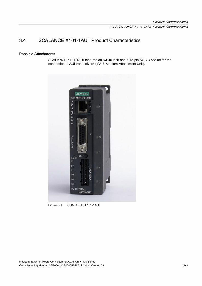
Possible Attachments SCALANCE X101-1AUI features an RJ-45 jack and a 15-pin SUB D socket for the connection to AUI transceivers (MAU, Medium Attachment Unit).
Figure 3-1 SCALANCE X101-1AUI
Industrial Ethernet Media Converters SCALANCE X-100 Series Commissioning Manual, 06/2006, A2B00051526A, Product Version 03 3-3

Product Characteristics 3.5 SCALANCE X101-1AUI TP-RJ-45 Interface
3.5 SCALANCE X101-1AUI TP-RJ-45 Interface
Connector pinout
RJ-45 jack
Figure 3-2 RJ-45 connector pinout
Pin number Pinout
Pin 8 NC Pin 7 NC Pin 6 TD- Pin 5 NC Pin 4 NC Pin 3 TD+ Pin 2 RD- Pin 1 RD+
On SCALANCE X101-1AUI, the twisted pair port is implemented as RJ-45 jack.
Notice
TP cords or TP-XP cords with a maximum length of 10 m can be connected to the RJ-45 TP port.
Depending on the cable type, a total cable length of up to 100 m is permitted between two devices with the IE FC cables and IE FC RJ-45 plug 180.
Note
The transmission mode of Scalance X101-1AUI is set to 10 Mbps half duplex.
Devices not supporting autonegotiation must be set to 10 Mbps / half duplex.
Industrial Ethernet Media Converters SCALANCE X-100 Series 3-4 Commissioning Manual, 06/2006, A2B00051526A, Product Version 03

Product Characteristics 3.6 SCALANCE X101-1AUI AUI Interface
MDI /MDIX Autocrossover Function The advantage of the MDI /MDIX autocrossover function is that straight-through cables can be used throughout and crossover Ethernet cables are unnecessary. This prevents malfunctions resulting from mismatching send and receive wires. This makes installation much easier for the user. All devices of the SCALANCE X-101 product line support the MDI / MDIX autocrossover function.
Note
Autopolarity is not supported.
3.6 SCALANCE X101-1AUI AUI Interface
Transmission Rate The transmission rate is 10 Mbps.
Transmission Mode The AUI transmission mode is specified in the IEEE 802.3 standard.
Since half duplex mode and the transmission rate of 10Mbps are specified, autonegotiation cannot be selected on the TP port.
Transmission Medium AUI cable (drop cable / EFB Ethernet transceiver cable)
Range The maximum transmission range (segment length) is 50 m.
Medium Attachment Unit – Supply At 12 V, maximally 500 mA are provided to a Medium Attachment Unit.
Connectors Interlocking 15-pin SUB-D connectors are used for the connection.
Industrial Ethernet Media Converters SCALANCE X-100 Series Commissioning Manual, 06/2006, A2B00051526A, Product Version 03 3-5

Product Characteristics 3.6 SCALANCE X101-1AUI AUI Interface
Connector pinout
SUB-D socket (female)
Figure 3-3 15-pin SUB-D connector pinout
Pin number Pinout
Shield Ground (M-GND) Pin 15 NC Pin 14 Ground (M-GND) Pin 13 Voltage Plus (12V +) Pin 12 DIN (Data In -) Pin 11 Ground (M-GND) Pin 10 DON (Data Out -) Pin 9 CIN (Control In -) Pin 8 Ground (M-GND) Pin 7 NC Pin 6 Voltage Neg (12V -) Pin 5 DIP (Data In +) Pin 4 Ground (M-GND) Pin 3 DOP (Data Out +) Pin 2 CIP (Control In +) Pin 1 Ground (M-GND)
Industrial Ethernet Media Converters SCALANCE X-100 Series 3-6 Commissioning Manual, 06/2006, A2B00051526A, Product Version 03

Product Characteristics 3.7 SCALANCE X101-1AUI Power Supply and Signaling Contact
3.7 SCALANCE X101-1AUI Power Supply and Signaling Contact
Power Supply The power supply is connected using a 4-pin plug-in terminal block. The power supply can be connected redundantly. Both inputs are isolated. There is no distribution of load. When using a redundant power supply, the power supply unit with the higher output voltage supplies SCALANCE X101-1AUI alone. The power supply is connected over a high resistance with the enclosure to allow an ungrounded setup.
Figure 3-4 SCALANCE X101-1AUI power supply Figure 3-5 Connector pinout
Pin number Pinout Pin 1 L1+ (+18 - 32V DC) Pin 2 M1 (ground) Pin 1 M2 (ground) Pin 2 L2+ (+18 - 32V DC)
Warning
The SCALANCE X101-1AUI device is designed for operation with safety extra-low voltage. This means that only safety extra-low voltages (SELV) complying with IEC950/EN60950/ VDE0805 can be connected to the power supply terminals.
The power supply unit to supply SCALANCE X101-1AUI must comply with NEC Class 2 (voltage range 18-32 V, current requirement 470 mA).
If the device is connected to a redundant power supply (two separate power supplies), both must meet these requirements.
The signaling contact can be subjected to a maximum load of 100 mA (safety extra-low voltage (SELV), DC 24 V).
Never connect SCALANCE X101-1AUI to AC voltage. Never operate SCALANCE X101-1AUI with DC voltage higher than 32 V DC.
Industrial Ethernet Media Converters SCALANCE X-100 Series Commissioning Manual, 06/2006, A2B00051526A, Product Version 03 3-7

Product Characteristics 3.8 SCALANCE X101-1AUI Button
Signaling Contact The signaling contact is connected to a 2-pin plug-in terminal block. The signaling contact (optical relay contact) is a floating switch with which error/fault states are signaled by contact separation.
Figure 3-6 SCALANCE X101-1AUI signaling contact
Figure 3-7 Connector pinout
Pin number Pinout
Pin 1 F1 Pin 2 F2
The following errors/faults can be signaled by the signaling contact: • The failure of the link on the monitored TP port (P1). • The failure of one of the two redundant power supply units. Connecting or disconnecting a communication node on the unmonitored port (P2) does not cause an error message. The signaling contact remains activated until the error/fault is eliminated or until the current status is applied as new desired status by the button. When turning off the device, the signaling contact is always activated (open).
3.8 SCALANCE X101-1AUI Button
What is the function of the button? Using the button, you can display and modify the set fault mask.
After continuously pressing the button, the currently valid fault mask is displayed for approximately 3 seconds. The LED of the monitored port flashes at a frequency of 5 Hz.
Keep the button pressed to modify the fault mask. After another 3 seconds, the current link status of port P1 and the indicator of the power supply LEDs are displayed at a flashing frequency of 2.5 Hz. Keep the button pressed. After another 3 seconds, this status is applied as new fault mask and saved. The now monitored port is indicated by the permanently lit P1-LED until the button is released. As long as the LED is still flashing, the saving can be canceled by releasing the button.
Industrial Ethernet Media Converters SCALANCE X-100 Series 3-8 Commissioning Manual, 06/2006, A2B00051526A, Product Version 03

Product Characteristics 3.8 SCALANCE X101-1AUI Button
If an empty fault mask (P1 is not monitored) is set or is to be set, P1-LED flashes at a frequency of 2.5 Hz. Simultaneously with the fault mask, the monitoring of the connected power supply is set. The existence of the two power supply units is only monitored if both power supplies are connected during saving the fault mask.
The failure of the link on the monitored port P1 or of one of the monitored power supplies is indicated by the illuminated red error LED. The signaling contact is opened simultaneously.
Note
The factory default is no port monitoring of port P1 but monitoring of the power supply L1+/M1. If necessary, error LED and signaling contact have to be cleared by pressing the button for an appropriate period or the feeding point has to be changed when connecting only one power supply to L2+/M2.
The setting remains after turning off/on.
Industrial Ethernet Media Converters SCALANCE X-100 Series Commissioning Manual, 06/2006, A2B00051526A, Product Version 03 3-9

Product Characteristics 3.9 SCALANCE X101-1AUI LEDs
3.9 SCALANCE X101-1AUI LEDs
Fault indicator (red LED)
Status Meaning Lit red SCALANCE X101-1AUI detects an error. Simultaneously the
signaling contact opens. The following errors are detected:
1. Link down event on the monitored port P1
2. Failure of the supply voltage or supply voltage less than 14 V of one of the two redundant power supplies. See also note in chapter 3.8
Not lit No error was detected by SCALANCE X101-1AUI.
Power indicator (green LED) The status of the power supply is indicated by a green LED:
Status Meaning Lit green Power supplies L1 or L2 are connected. Not lit Power supplies L1 and L2 are not connected or L1 and
L2 <14 V. Comment: If the green LED is not lit, no other signal LED is lit.
Port status indicator (green/yellow LEDs) The status of the ports is indicated by 2 LEDs:
Status Meaning Port 1: LED lit green TP link exists, no data reception Port 1: LED lit yellow TP link exists, data received on TP port Port 2: LED lit yellow Bidirectional data communication on AUI port P2 Port 1: LED flashes yellow Setting or display of the fault mask
Transparent link display (green LED) “TL” (transparent link) LED: The TL LED has no function.
Status Meaning Not lit Stand-alone mode.
The TL function (transparent link) is not possible.
A direct cascade connection of two SCALANCE X101-1AUI media converters is not possible, thus no transparent link.
Industrial Ethernet Media Converters SCALANCE X-100 Series 3-10 Commissioning Manual, 06/2006, A2B00051526A, Product Version 03

Product Characteristics 3.10 SCALANCE X101-1AUI Technical Specifications
3.10 SCALANCE X101-1AUI Technical Specifications
Technical Specifications of SCALANCE X101-1AUI
Ports Attachment of DTEs or network components over twisted pair
1xRJ-45 socket with MDI-X pinning 10 Mbps (half duplex according to 10BaseT)
Connection of further network components via AUI cable (drop cable)
1x 15-pin SUB-D socket (10 Mbps, half duplex)
Connector for power supply 1x4-pin plug-in terminal block Connector for signaling contact 1x2-pin plug-in terminal block Electrical DataPower supply 2 x DC 24 V
(DC 18 - 32 V) safety extra-low voltage (SELV)
Power loss at DC 24 V (typ.) 3 W Current consumption at rated voltage (typ.) - at 2.1 W on 12V AUI output - at 6.0 W on 12V AUI output
160 mA 350 mA
Overvoltage protection at input PTC resettable fuse (1.0 A) Max. permitted power consumption of the load at the 12V AUI output (MAU)
6 W (500 mA / 12V)
Permitted Cable Lengths Network span parameter/TP cable length 0 –100 m 0 –85 m
IE FC TP standard cable with IE FC RJ-45 plug 180 or IE FC outlet RJ-45 with IE FC TP standard cable (0 - 90 m) + 10 m TP cord IE FC TP marine/trailing/flexible with IE FC RJ-45 plug 180 or IE FC TP marine/trailing/flexible (0 – 75 m) + 10 m TP cord over IE FC outlet RJ-45
Network span parameter/AUI cable length 0 - 50 m
AUI cable (drop cable)
Industrial Ethernet Media Converters SCALANCE X-100 Series Commissioning Manual, 06/2006, A2B00051526A, Product Version 03 3-11

Product Characteristics 3.10 SCALANCE X101-1AUI Technical Specifications
Permitted Environmental Conditions / EMC Operating temperature -10°C to +60°C Storage/transport temperature --40°C to +80°C Relative humidity in operation ‹ 95% (no condensation) Operating altitude 2000 m at max 56 °C ambient temperature
3000 m at max. 50 °C ambient temperature RF interference level EN 61000-6-2 Class B
(replaces EN 50081-2 Class B) Noise immunity EN 61000-6-4
(replaces EN 50082-2) Degree of protection IP30 Approvals
UL 60950 c-UL-us CSA C22.2 No. 60950
c-Ul-us for hazardous locations 1 UL 1604, UL 2279Pt.15 CL. 1, Div. 2 GP. A.B.C.D T.. CL. 1, Zone 2, GP. IIC, T.. CL. 1, Zone2, AEx nC IIC T..
FM 1 FM 3611 CL. 1, Div. 2 GP. A.B.C.D T.. CL. 1, Zone 2, GP. IIC, T.. Ta: ..
C-Tick AS/NZS 2064 (Class A). CE EN 61000-6-2, EN 61000-6-4
(replaces EN 50081-2) ATEX Zone 2 1 EN600079-15
II 3 G EEx nA II T.. KEMA 06 ATEX 0021 X
MTBFMTBF 136years Construction Dimensions (W x H x D) in mm 40 x 125 x 124 Weight in g 560 Installation options DIN rail
S7-300 DIN rail Wall mounting
1 Temperature code "T.." and maximum ambient temperature "Ta: .." as indicated on marking plate
Industrial Ethernet Media Converters SCALANCE X-100 Series 3-12 Commissioning Manual, 06/2006, A2B00051526A, Product Version 03

Product Characteristics 3.10 SCALANCE X101-1AUI Technical Specifications
Order Numbers SCALANCE X101-1AUI 6GK5101-1BX00-2AA3 "Industrial Ethernet TP and Fiber Optic Networks" manual
6GK1970-1BA10-0AA0
IE FC stripping tool 6GK1901-1GA00 IE FC blade cassettes 6GK1901-1GB00 IE FC TP standard cable GP 6XV1840 2AH10 IE FC TP trailing cable 6XV1840-3AH10 IE FC TP marine cable 6XV1840-4AH10 IE FC TP trailing cable GP 6XV1870-2D IE FC TP flexible cable GP 6XV1870-2B IE FC RJ-45 plug 180 pack of 1 6GK1 901-1BB10-2AA0 IE FC RJ-45 plug 180 pack of 10 6GK1 901-1BB10-2AB0 IE FC RJ-45 plug 180 pack of 50 6GK1 901-1BB10-2AE0
Note
When a frame passes through the SCALANCE X101-1AUI media converter, it is typically delayed by approx. 40 µs by the "Cut Through" function of the internal switch. - At a network load of 100%, these times can increase system-dependently (max. 180 µs).
Industrial Ethernet Media Converters SCALANCE X-100 Series Commissioning Manual, 06/2006, A2B00051526A, Product Version 03 3-13


Installation and Maintenance 44.1 Installation
Types of Installation SCALANCE X101-1AUI can be installed in various ways: • Installation on a 35 mm DIN rail • Installation on a SIMATIC S7-300 DIN rail • Wall mounting
Note
When installing and operating the device, keep to the installation instructions and safety-related notices as described here and in the SIMATIC NET Industrial Ethernet Twisted Pair and Fiber Optic Networks /2/ manual.
Note
Protect the device against exposure to direct sunlight by suitable shadowing. This avoids an undesired temperature rise of the device and prevents premature ageing of device and cabling.
Warning
If the cable or conduit entry point exceeds 70°C or the branching point of conductors exceeds 80°C special precautions must be taken. If the equipment is operated in an air ambient of 50°C - 60 °C, only use cables with admitted maximum operating temperature of at least 80°C.
Warning
Provisions shall be made to prevent the rated voltage from being exceeded by transient disturbances of more than 40%. This criteria is fulfilled, if supplies are derived from SELV (Safety Extra Low Voltage), only..
Industrial Ethernet Media Converters SCALANCE X-100 Series Commissioning Manual, 06/2006, A2B00051526A, Product Version 03 4-1

Installation and Maintenance 4.1 Installation
4.1.1 Installation on a DIN Rail
Installation Install the media converter on a 35 mm DIN rail according to DIN EN 50022. 1. Place the upper catch of the device over the top of the rail and then push in the lower part
of the device against the rail until it clips into place. 2. Install the electrical connecting cables for the power supply and the terminal block for the
signaling contact. 3. Plug the terminal blocks in the corresponding sockets on the device.
Figure 4-1 Installation on a DIN rail (35 mm)
Industrial Ethernet Media Converters SCALANCE X-100 Series 4-2 Commissioning Manual, 06/2006, A2B00051526A, Product Version 03

Installation and Maintenance 4.1 Installation
Uninstalling To remove SCALANCE X101-1AUI from the rail: 1. First disconnect the TP cable and the AUI cables. Remove the terminal block for the
power supply and the signaling contact. 2. Use a screwdriver to release the lower rail catch of the device and pull the lower part of
the device away from the rail.
Figure 4-2 Removing from a DIN rail (35 mm)
Industrial Ethernet Media Converters SCALANCE X-100 Series Commissioning Manual, 06/2006, A2B00051526A, Product Version 03 4-3

Installation and Maintenance 4.1 Installation
4.1.2 Installation on a DIN Rail
Installation on a SIMATIC S7-300 DIN rail 1. Place the upper guide at the top of the SCALANCE housing in the S7 standard rail. 2. Screw the media converter of the SCALANCE X-100 series to the underside of the DIN
rail. 3. Fit the connectors for the power supply. 4. Fit the connectors for the signaling contact. 5. Plug the terminal blocks in the corresponding sockets on the device.
Figure 4-3 Installation on a SIMATIC S7-300 DIN rail
Uninstalling To remove the media converters of the SCALANCE X-100 series from the SIMATIC S7-300 DIN rail: 1. First remove all connected cables. 2. Unscrew the screw fittings at the lower part of the standard rails and subsequently pull
the device away from the standard rail.
Industrial Ethernet Media Converters SCALANCE X-100 Series 4-4 Commissioning Manual, 06/2006, A2B00051526A, Product Version 03

Installation and Maintenance 4.2 Grounding
4.1.3 Wall Mounting
Wall mounting 1. Depending on the surface, use suitable installation material for wall mounting (e.g. for
mounting in concrete: Four wall plugs with a diameter of 6 mm and a length of 30 mm, 4 screws with a diameter of 3.5 mm and a length of 40 mm).
2. Install the electrical connecting cables. 3. Fit the connectors for the signaling contact. 4. Plug the terminal blocks in the corresponding sockets on the device. For exact dimensions please observe the dimension drawing in chapter 7 of this manual.
Note
The wall mounting must be capable of supporting at least four times the weight of the device.
4.2 Grounding
Installation on a DIN Rail The device is grounded over the DIN rail.
S7 DIN Rail The device is grounded over its rear panel and the neck collar screw.
Wall mounting The device is grounded by the securing screw in the unpainted hole.
Please note that SCALANCE X101-1AUI must be grounded over one securing screw with minimum resistance. If a device of the SCALANCE X100 product line is mounted on a non-conducting surface, it is required to install a grounding cable. The grounding cable is not included in the delivery. Connect the unpainted surface of the device to the next grounding point via the grounding cable.
Industrial Ethernet Media Converters SCALANCE X-100 Series Commissioning Manual, 06/2006, A2B00051526A, Product Version 03 4-5

Installation and Maintenance 4.3 Assembling the IE FC Standard Cable
4.3 Assembling the IE FC Standard Cable
Assemble the IE FC RJ-45 plug 180 and the IE FC standard cable as follows For information on the assembly, please refer to the instructions that ship with the IE FC RJ-45 plug 180. The robust connectors of the nodes are designed for industry and are PROFINET-compliant. Due to the locking mechanism on the casing, they provide additional strain and torsion relief.
Figure 4-4 IE FC RJ-45 plug 180
Industrial Ethernet Media Converters SCALANCE X-100 Series 4-6 Commissioning Manual, 06/2006, A2B00051526A, Product Version 03

Installation and Maintenance 4.3 Assembling the IE FC Standard Cable
Inserting the IE FC RJ-45 plug 180 Insert the IE FC RJ-45 plug 180 in the twisted pair port of SCALANCE X005 or of the devices of the product lines SCALANCE X-100 or X-200 until it snaps into place.
Figure 4-5 Inserting the IE FC RJ-45 plug 180
Due to the closing shape and the latching with the PROFINET-compliant connector IE FC RJ-45 plug 180, the sleeve at the TP port of SCALANCE X101-1AUI ensures a robust, industry-standard node connection which provides additional strain and torsion relief of the twisted pair port.
Industrial Ethernet Media Converters SCALANCE X-100 Series Commissioning Manual, 06/2006, A2B00051526A, Product Version 03 4-7

Installation and Maintenance 4.3 Assembling the IE FC Standard Cable
Removing the IE FC RJ-45 plug 180 Unlatch the IE FC RJ-45 plug 180 by slightly pressing the latching to remove the plug.
Figure 4-6 Unlatching the RJ-45 plug
If, for lack of space, a manual unlatching is not possible, you can also unlatch the plug with a 2.5 mm screwdriver. Subsequently you can remove the IE FC RJ-45 plug 180 from the twisted pair port.
Industrial Ethernet Media Converters SCALANCE X-100 Series 4-8 Commissioning Manual, 06/2006, A2B00051526A, Product Version 03

Installation and Maintenance 4.4 Assembling the AUI Cable
4.4 Assembling the AUI Cable
Assemble or disassemble the AUI cable (drop cable) as follows The 15-pin sub-D socket has a locking. To loosen the connector, press the locking down and press it up to close it.
Figure 4-7 Locking in open position
Figure 4-8 Locking or unlocking the SUB-D connector
Industrial Ethernet Media Converters SCALANCE X-100 Series Commissioning Manual, 06/2006, A2B00051526A, Product Version 03 4-9

Installation and Maintenance 4.5 Maintenance
4.5 Maintenance
Maintenance The devices of the product lines SCALANCE X-100 and X-200 are equipped with a self-resetting fuse (resettable fuse / PTC). If the fuse blows (all LEDs are off despite correctly applied power supply), the device should be disconnected from the power supply for approx. 30 minutes before it can be turned on again.
If a fault develops, please send the device to your SIEMENS service center for repair. Repairs on-site are not possible.
Industrial Ethernet Media Converters SCALANCE X-100 Series 4-10 Commissioning Manual, 06/2006, A2B00051526A, Product Version 03

Notes on the CE Mark 55.1 Notes on the CE Mark
Product Name
SIMATIC NET SCALANCE X101-1AUI 6GK5101-1BX00-2AA3
EMC Directive 89/336/EEC "Electromagnetic Compatibility"
Area of Application The products are designed for use in an industrial environment:
Area of Application Requirements Noise emission Noise immunity Industrial operation EN 61000-6-4 : 2001
(replaces EN 50082-2) EN 61000-6-2 : 2001 (replaces EN 50081-2)
Installation Guidelines The products meet the requirements if you keep to the installation instructions and safety-related notices as described here and in the SIMATIC NET Industrial Ethernet Twisted Pair and Fiber Optic Networks /1/ manual when installing and operating the device.
Industrial Ethernet Media Converters SCALANCE X-100 Series Commissioning Manual, 06/2006, A2B00051526A, Product Version 03 5-1

Notes on the CE Mark 5.1 Notes on the CE Mark
Conformity Certificates The EU declaration of conformity is available for the responsible authorities according to the above-mentioned EU directive at the following address: Siemens Aktiengesellschaft Bereich Automatisierungs- und Antriebstechnik Industrielle Kommunikation (A&D PT2) Postfach 4848 D-90327 Nürnberg
Notes for Manufacturers of Machines The products are not machines in the sense of the EC Machinery Directive. There is therefore no declaration of conformity for the EU directive on machines 89/392/EEC for these products.
If the products are part of the equipment of a machine, they must be included in the procedure for the declaration of conformity by the manufacturer of the machine.
Industrial Ethernet Media Converters SCALANCE X-100 Series 5-2 Commissioning Manual, 06/2006, A2B00051526A, Product Version 03

References 66.1 References
Sources of Information and Other Documentation 1. SIMATIC NET Industrial Twisted Pair and Fiber Optic Networks
Order numbers: 6GK1970-1BA10-0AA0 German 6GK1970-1BA10-0AA1 English 6GK1970-1BA10-0AA2 French 6GK1970-1BA10-0AA4 Italian
2. PROFINET Installation Guide can be ordered from the PROFIBUS User Organization (PNO)
Industrial Ethernet Media Converters SCALANCE X-100 Series Commissioning Manual, 06/2006, A2B00051526A, Product Version 03 6-1

Dimension Drawings 77.1 Dimension Drawing
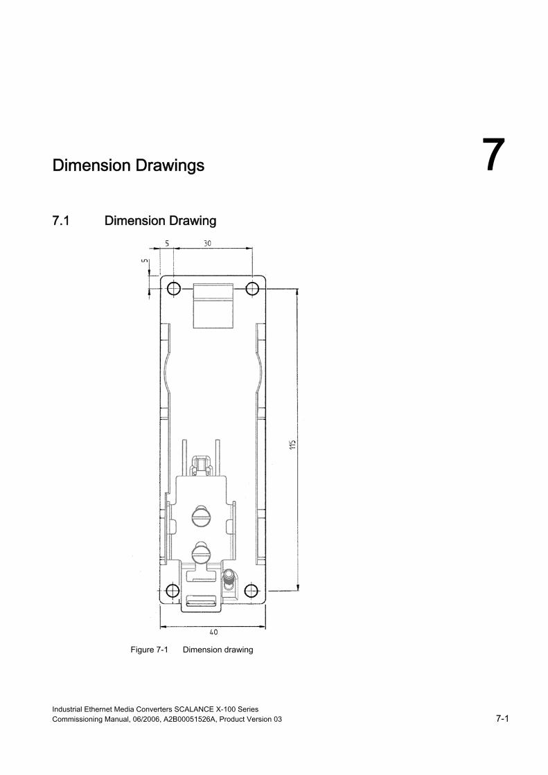
Figure 7-1 Dimension drawing
Industrial Ethernet Media Converters SCALANCE X-100 Series Commissioning Manual, 06/2006, A2B00051526A, Product Version 03 7-1

Dimension Drawings 7.1 Dimension Drawing
Figure 7-2 SCALANCE X101-1AUI side view
Industrial Ethernet Media Converters SCALANCE X-100 Series 7-2 Commissioning Manual, 06/2006, A2B00051526A, Product Version 03

Glossary
5-4-3 Rule See “repeater rule”
AUI Attachment Unit Interface. 10 Mbps TP port (15-pin sub D) for connecting an AUI cable (drop cable). Can be implemented either as DTE (data terminal equipment) or as DCE (data carrier equipment). Is primarily used for the connection to triax segments.
Autocrossover Method with which a TP port is automatically switched between MDI and MDI-X assignment to establish a connection independently of the port assignment of the device to be connected. This ensures that crossover cables are not required. The autocrossover function requires that the respective port is set to autonegotiation mode.
Autonegotiation Method standardized according to IEEE 802.3 with which transmission parameters (e.g. 10/100 Mbps, full / half duplex) between devices are automatically negotiated.
C-PLUG The C-PLUG (configuration plug) is a swap medium for backing up the configuration data. If the device is replaced, the configuration can be applied by exchanging the C-PLUG.
CRC Cyclic Redundancy Check. A checksum used in transmission protocols to detect errors in frames.
Cut Through With this method, a frame is forwarded as soon as the destination address is recognized. Therefore the delay does not depend on the frame length. However, if there are problems in a network, also defective frames are forwarded which may increase the network load.
Industrial Ethernet Media Converters SCALANCE X-100 Series Commissioning Manual, 06/2006, A2B00051526A, Product Version 03 Glossary-1

Glossary
Event for alarms & events: An event is any incident that could be of interest to a client. Although events can also be generated when a condition is met, it is not necessary that they are linked to a condition. Events not linked to conditions include e.g. error messages of the communication system.
FO Fiber optic
MAU Medium Attachment Unit. MAU designates the transceiver which implements the actual access to the transmission medium (yellow cable). See page 2-1
Signaling Contact Floating relay contact via which detected error/fault states are signaled.
Fault Mask Definition of a desired status (good status); deviations from this status during operation are considered as errors/faults.
Monomode The monomode fiber (also single-mode fiber) typically has a core diameter of 5 to 9 µm. However, the outer diameter is also 125 µm. The actual transmission of the information takes place in the core of the fiber.
Multicast A frame with a multicast address is received by all recipients which are ready for receiving this address.
Multimode In multimode transmission, the pulse is transferred using many modes (waves) which travel along curved paths or which are reflected within the core. Attenuation is mainly caused by physical absorption and dispersion as well as by mechanical bending. Among other things, the amount of attenuation depends on the wavelength of the input light. Multimode fiber-optic cables have an outer diameter of 125 µm and a core diameter of 50 or 62.5 µm. Due to the larger core diameter, the pulse edges degrade more than in single mode transmission, which results in shorter transmission distances.
OSM Optical Switching Module – SIMATIC NET Ethernet switch with optical ports.
Industrial Ethernet Media Converters SCALANCE X-100 Series Glossary-2 Commissioning Manual, 06/2006, A2B00051526A, Product Version 03

Glossary
Redundancy Manager (RM) Switch in a ring topology which does not forward frames between its ring ports in case of functioning connections between all other switches. As soon as a connection between two switches is interrupted, the redundancy manager forwards frames between its ring ports to re-establish an intact connection between all switches.
Reconfiguration Time Time required to restore a functional configuration in case of a device failure or an interruption of a connection line.
Repeater Rule The repeater rule, also referred to as 5-4-3 rule, specifies that a maximum of 5 segments with 4 repeaters may be used in an Ethernet network with shared access in a star topology (10Base2, 10Base5, 10BaseT) and that active DTEs are only connected to 3 segments. The active DTEs also include the repeater.
Ring Port Two ports in a switch via which it is connected with other switches to form a ring. One switch in the ring must be configured as redundancy manager. This switch sends test frames via the ring ports that are forwarded by all ring ports of other switches in the ring. This ensures that the ring does not have any interruptions.
Segment In the Ethernet bus system, the transceivers connected over the bus cable along with the nodes connected over patch cables form a segment. Several such segments can be connected via repeaters. When using twisted pair and fiber-optic cables, each subsection forms one segment.
Store and Forward An entire frame is received, its validity checked (checksum, length etc.) and then buffered. Invalid frames are discarded, i.e. a frame is forwarded only if it is error-free.
TP Port Port with TP connector (RJ-45 jack)
Yellow Cable Yellow cable is a coaxial cable of the PG 8 type with an impedance of 50 Ohm. The Ethernet standard stipulates a yellow color – thus “yellow cable”. The ends must be provided with terminating resistors for scheduling.
Industrial Ethernet Media Converters SCALANCE X-100 Series Commissioning Manual, 06/2006, A2B00051526A, Product Version 03 Glossary-3


Index
A ATEX, 1-2 ATEX100a, 1-2
B Button, 3-8
C Connector pinout
RJ-45, 3-4 SUB-D, 3-6
C-Tick mark, 1-2
F Fault indicator (red LED), 3-10 Fuse, 4-10
M MAU, 3-3 MDI /MDIX Autocrossover Function, 3-5
N Network topology
Coupling of network segments, 2-1
P Port status indicator (green/yellow LEDs), 3-10 Possible attachments, 3-3 Power indicator (green LED), 3-10 Power supply, 3-7
S Signaling contact, 3-8
T Transparent link display (green LED), 3-10
U UL mark, 1-2
Industrial Ethernet Media Converters SCALANCE X-100 Series Commissioning Manual, 06/2006, A2B00051526A, Product Version 03 Index-1