4 functional decomposition
TRANSCRIPT
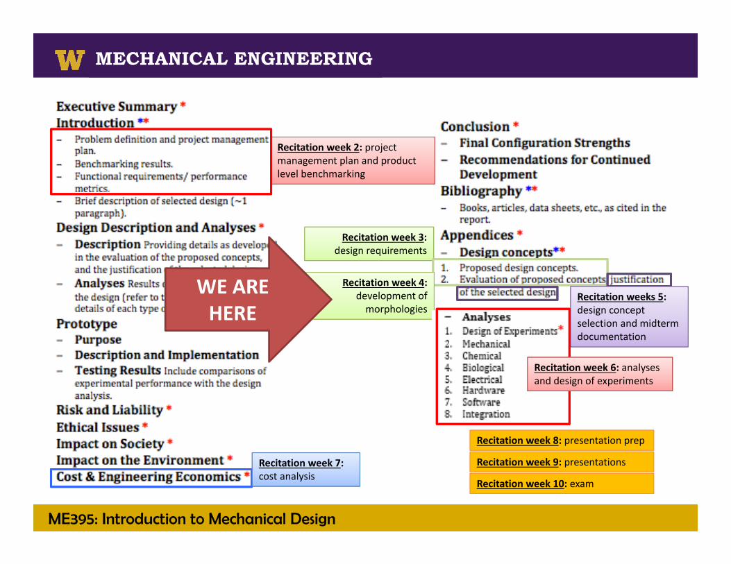
ME395: Introduction to Mechanical Design
MECHANICAL ENGINEERING
Recitation week 2: project management plan and product level benchmarking
Recitation week 3: design requirements
Recitation week 4: development of morphologies
Recitation week 7: cost analysis
Recitation week 8: presentation prep
Recitation week 9: presentations
Recitation week 10: exam
Recitation weeks 5: design concept selection and midterm documentation
Recitation week 6: analyses and design of experiments
WE ARE HERE
ME395: Introduction to Mechanical Design
MECHANICAL ENGINEERINGMECHANICAL ENGINEERING
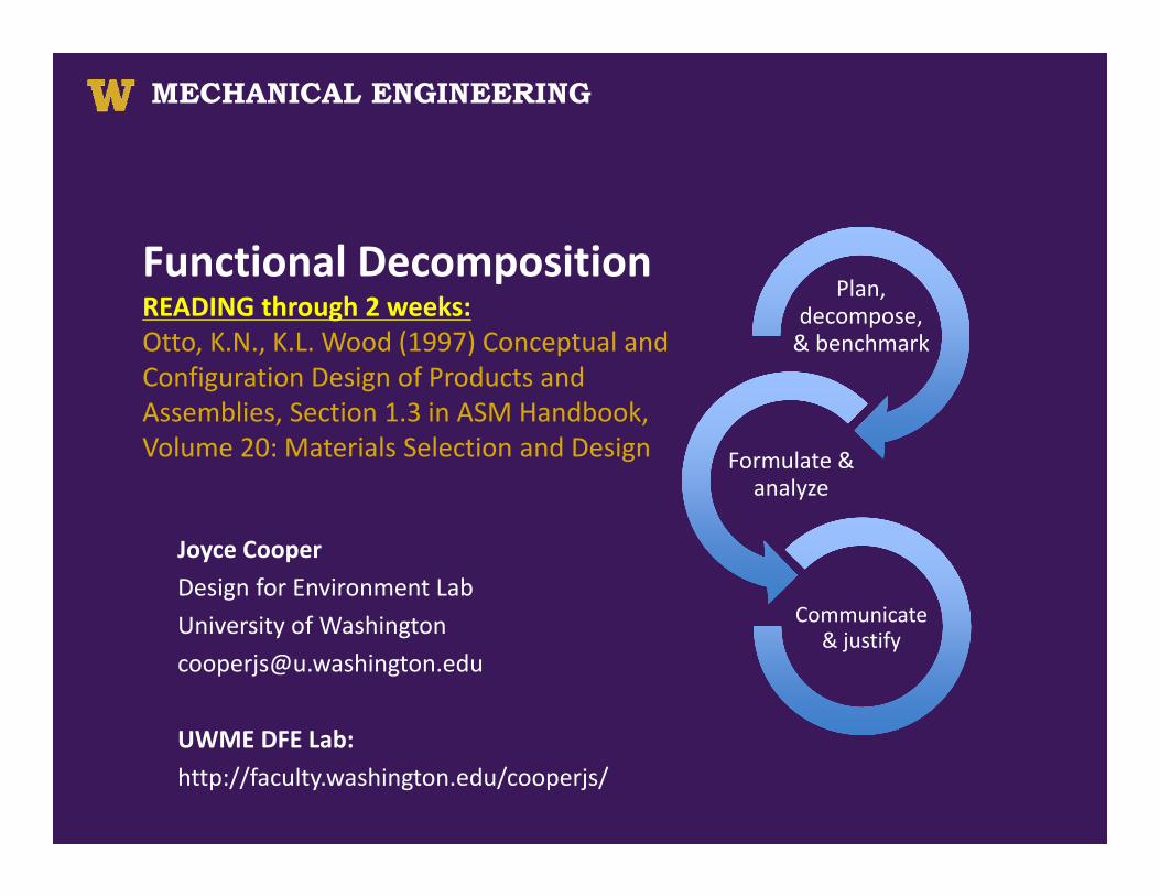
Functional DecompositionREADING through 2 weeks:Otto, K.N., K.L. Wood (1997) Conceptual and Configuration Design of Products and Assemblies, Section 1.3 in ASM Handbook, Volume 20: Materials Selection and Design
Joyce CooperDesign for Environment LabUniversity of [email protected]
UWME DFE Lab: http://faculty.washington.edu/cooperjs/
Plan, decompose, & benchmark
Formulate & analyze
Communicate & justify
ME395: Introduction to Mechanical Design
MECHANICAL ENGINEERING
Solid Fuels Processing Technologies
MECHANICAL ENGINEERING
Starting with Design Requirements
• It seems that everyone agrees that design requirements must describe “what” must be done not “how” something should be done.
• There seems however to be disagreement concerning definitiveness. Should you…
• Avoid using the words “must” and “should” OR• Define each requirement as an explicit statement that contains a shallword that fully defines “what the design must do”.
ME395: Introduction to Mechanical Design
MECHANICAL ENGINEERING
Solid Fuels Processing Technologies
MECHANICAL ENGINEERING
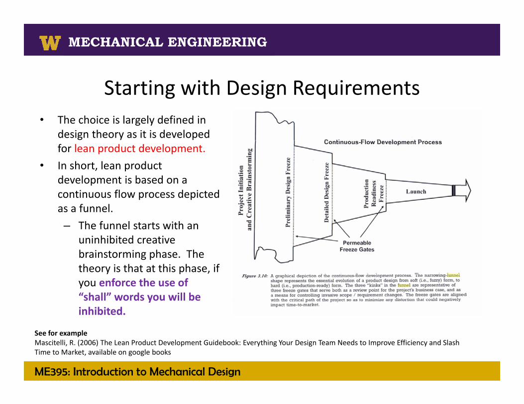
Starting with Design Requirements• The choice is largely defined in
design theory as it is developed for lean product development.
• In short, lean product development is based on a continuous flow process depicted as a funnel.– The funnel starts with an
uninhibited creative brainstorming phase. The theory is that at this phase, if you enforce the use of “shall” words you will be inhibited.
See for example Mascitelli, R. (2006) The Lean Product Development Guidebook: Everything Your Design Team Needs to Improve Efficiency and Slash Time to Market, available on google books
ME395: Introduction to Mechanical Design
MECHANICAL ENGINEERING
Solid Fuels Processing Technologies
MECHANICAL ENGINEERING
Starting with Design Requirements
• So if we keep around a mix of requirements that • Avoid using the words “must” and “should” AND• Define each requirement as an explicit statement that contains ashallword that fully defines “what the design must do”.
• We find that the former VERY OFTEN is where the real innovation opportunities are found.
• A variation on this theme is the use of a scheme to rank or weight needs or requirements in the customer experience. This CAN ALSO inhibited creative brainstorming.– For example, Otto and Wood (1997) suggest a method of Summarizing
Customer Needs based on a scale (0 to 1, 1 to 10, etc.) ….. we will use similar methods AFTER we have a BIG set of concepts to consider.
ME395: Introduction to Mechanical Design
MECHANICAL ENGINEERING
Solid Fuels Processing Technologies
MECHANICAL ENGINEERING
Functional Decomposition
• Product research• Defining customer experience
needs • Translating research and needs
to requirements• Developing product
morphologies using functional decomposition
ME395: Introduction to Mechanical Design
MECHANICAL ENGINEERING
Solid Fuels Processing Technologies
MECHANICAL ENGINEERING
Product morphologies
• Morphology is the study of shape or form– Morphological analysis creates new shapes or forms
– The purpose here is to uncover combinations of ideas (subfunction concepts) that combine into design concepts
Dieter, G., 2000, Engineering Design A Materials and Processing Approach, Third Edition, McGraw Hill
ME395: Introduction to Mechanical Design
MECHANICAL ENGINEERING
Solid Fuels Processing Technologies
MECHANICAL ENGINEERING
Developing the product morphology
• Two types of decomposition– Decomposition in the Physical Domain
• decompose the product into subassemblies/ components
– Improve on each
– Decomposition in the Functional Domain• decompose the product into subfunctions
– Innovate on each– Emphasis is placed on what is to be achieved not how it is achieved.
Dieter, G., 2000, Engineering Design A Materials and Processing Approach, Third Edition, McGraw Hill

ME395: Introduction to Mechanical Design
MECHANICAL ENGINEERING
Solid Fuels Processing Technologies
MECHANICAL ENGINEERING
Functional Decomposition
• A “function” of a product is a clear, reproducible relationship between the available inputs and the desired outputs of a product, independent of any particular form.
• The “product function” is the overall intended function of the product– what it is to do.
From Otto and Wood (2001) Product Design: Techniques in Reverse Engineering and New Product Development

ME395: Introduction to Mechanical Design
MECHANICAL ENGINEERING
Solid Fuels Processing Technologies
MECHANICAL ENGINEERING
Functional Decomposition
• The product function is the simplest representation of the product, usually just an active verb and a noun:
– Iron clothes, chop beans, make copies, loosen screws, …
• Based on the overall function, we next decompose the function into subfunctions and so on
From Otto and Wood (2001) Product Design: Techniques in Reverse Engineering and New Product Development
ME395: Introduction to Mechanical Design
MECHANICAL ENGINEERING
Solid Fuels Processing Technologies
MECHANICAL ENGINEERING
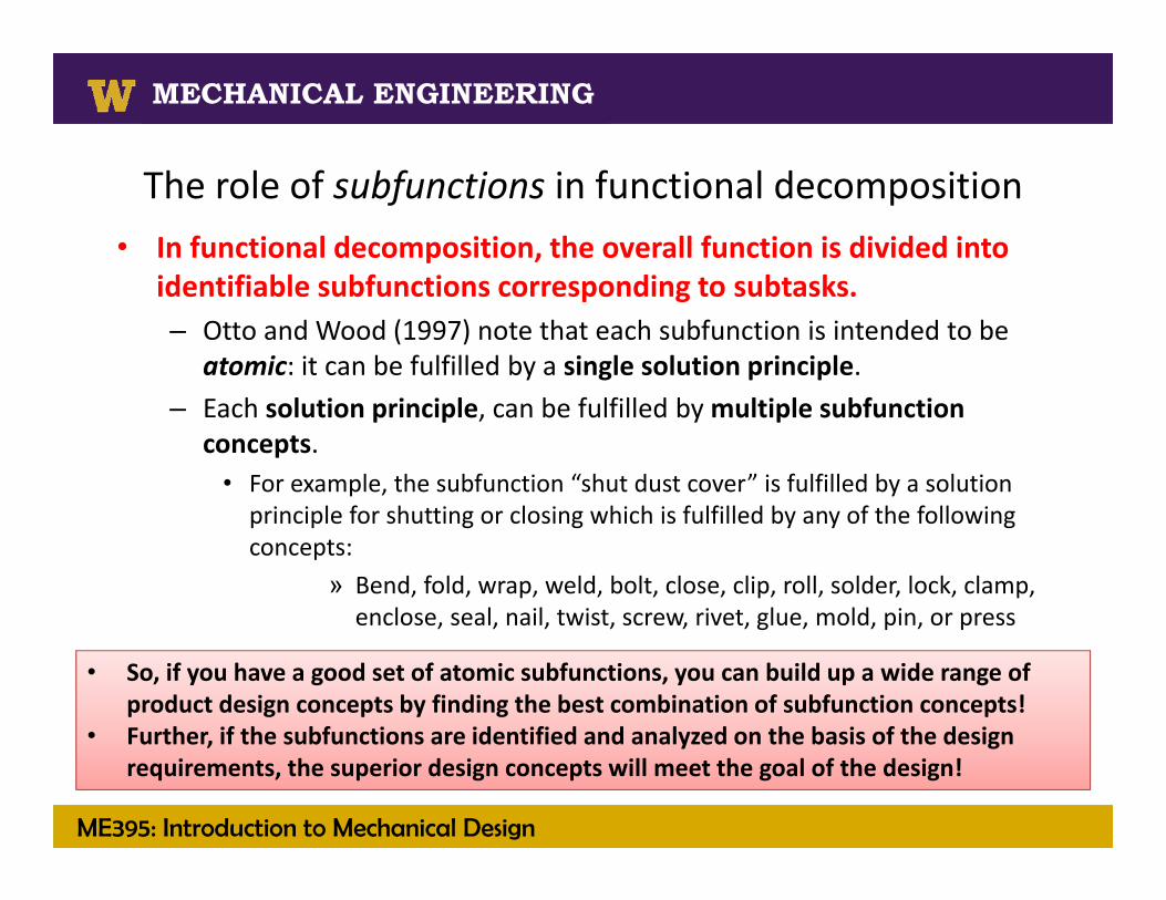
The role of subfunctions in functional decomposition • In functional decomposition, the overall function is divided into
identifiable subfunctions corresponding to subtasks. – Otto and Wood (1997) note that each subfunction is intended to be
atomic: it can be fulfilled by a single solution principle. – Each solution principle, can be fulfilled by multiple subfunction
concepts.• For example, the subfunction “shut dust cover” is fulfilled by a solution principle for shutting or closing which is fulfilled by any of the following concepts:
» Bend, fold, wrap, weld, bolt, close, clip, roll, solder, lock, clamp, enclose, seal, nail, twist, screw, rivet, glue, mold, pin, or press
• So, if you have a good set of atomic subfunctions, you can build up a wide range of product design concepts by finding the best combination of subfunction concepts!
• Further, if the subfunctions are identified and analyzed on the basis of the design requirements, the superior design concepts will meet the goal of the design!
ME395: Introduction to Mechanical Design
MECHANICAL ENGINEERING
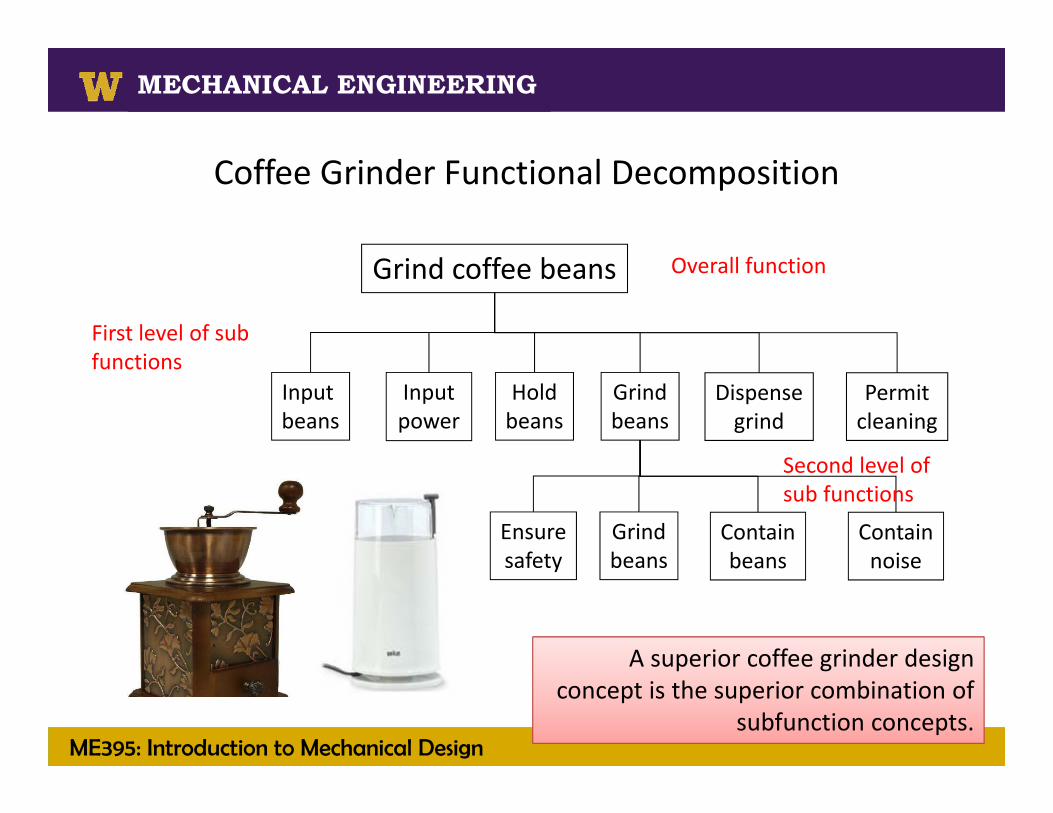
Coffee Grinder Functional Decomposition
Grind coffee beans
Input beans
Inputpower
Holdbeans
Grindbeans
Dispensegrind
Permitcleaning
Ensuresafety
Grindbeans
Containbeans
Containnoise
Overall function
First level of sub functions
Second level of sub functions
A superior coffee grinder design concept is the superior combination of
subfunction concepts.

Loosen/ tighten screws
Pick‐up & holdscrewdriver
Uninstall & install bits
Secure screw Rotate screw Store bits, & screws
Screwdriver Functional Decomposition
Accept and reject
bit
Secure bit
Grip
House electronics
Supply power
Use energy Generate torque
Actuate energy
Regulate energy
Convert energy
to torque
Apply torque
Transmit torque
Rotate screw
Changetorque
Transmittorque
Rotate bit
Withstand forces
Dissipatetorque
Supply or store energy/ recharge
Interface with user
Energy status
Safety/ off switch
Interface with user
Torque status
Overall function
A superior screwdriver design concept is the superior combination of subfunction concepts.

ME395: Introduction to Mechanical Design
MECHANICAL ENGINEERING
Solid Fuels Processing Technologies
MECHANICAL ENGINEERING
Develop and validate subfunction concepts
The role of subfunctions in functional decomposition
• Since subfunctions are so important to building‐up the superior design concept, it seems the identification of subfunctions is very important.
• For functional decomposition, Otto and Wood (1997) describe a 5 phase process:– Phase 1: Develop activity diagrams– Phase 2: Formulate sub functions through black box modeling and task listing– Phase 3: Aggregate subfunctions into a refined function structure
– Phase 4: Validate the functional decomposition– Phase 5: Establish and identify product architecture and assemblies
• Here, for the purpose of executing the process in just 10‐weeks, we present an alternative to phases 2‐5 based on a hierarchical information structure.
Develop a function structure
ME395: Introduction to Mechanical Design
MECHANICAL ENGINEERING
Solid Fuels Processing Technologies
MECHANICAL ENGINEERING
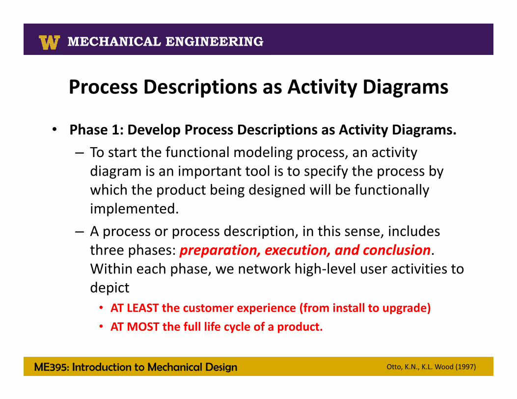
Process Descriptions as Activity Diagrams
• Phase 1: Develop Process Descriptions as Activity Diagrams. – To start the functional modeling process, an activity diagram is an important tool is to specify the process by which the product being designed will be functionally implemented.
– A process or process description, in this sense, includes three phases: preparation, execution, and conclusion. Within each phase, we network high‐level user activities to depict
• AT LEAST the customer experience (from install to upgrade)• AT MOST the full life cycle of a product.
Otto, K.N., K.L. Wood (1997)

ME395: Introduction to Mechanical Design
MECHANICAL ENGINEERING
Phase 1: Process Descriptions as Activity Diagramsfingernail clipper example
Otto, K.N., K.L. Wood (1997)
preparation
execution
conclusion
In Otto and Wood’s fingernail clipper example, the process description is represented as an activity diagram (Fig. 5). This diagram shows a number of subprocesses that describe the customer experience.

ME395: Introduction to Mechanical Design
MECHANICAL ENGINEERING
Solid Fuels Processing Technologies
MECHANICAL ENGINEERING
Phases 2‐3: Develop a function structureOtto and Wood’s method
• Phase 2: Formulate subfunctions through black box modeling and task listing
• Phase 3: Aggregate subfunctions into a refined function structure
– Otto and Wood (1997) present a method for developing subfunctionsthat starts with a black box model which depicts all input and output flows for the primary, high‐level function of the design task.
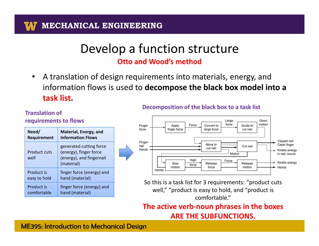
– Next, a translation of design requirements into materials, energy, and information flows is used to decompose the black box model into a task list.
– Next, subfunctions within the task list are aggregated to form a refined function structure.
Develop a function structure

ME395: Introduction to Mechanical Design
MECHANICAL ENGINEERING
Solid Fuels Processing Technologies
MECHANICAL ENGINEERING
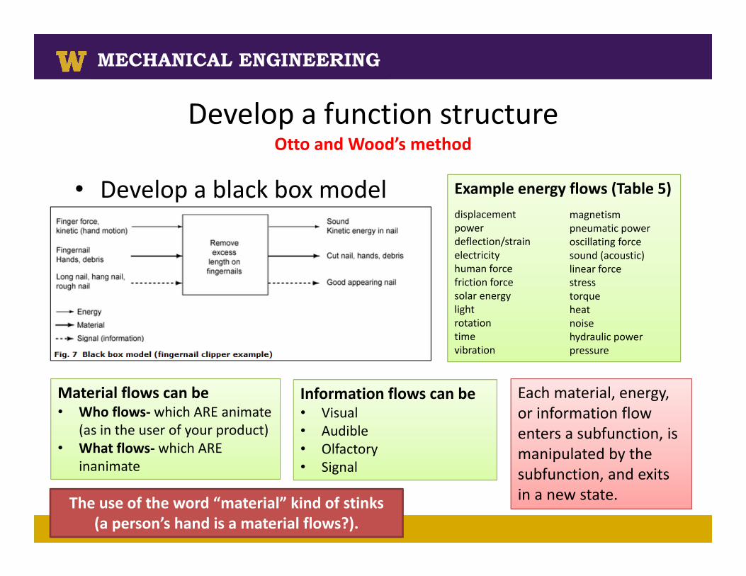
Develop a function structureOtto and Wood’s method
• Develop a black box model
• A black box model depicts all input and output flows for the primary, high‐level function of the design task, stated in active verb‐noun phrases. In the context of input‐output modeling, a flow enters an operation or subfunction, is manipulated by the subfunction, and exits in a new state.
• A flow is a physical phenomenon (e.g., material, energy, or signal) that is intrinsic to a product operation or subfunction. In the context of input‐output modeling, a flow enters an operation or subfunction, is manipulated by the subfunction, and exits in a new state.
ME395: Introduction to Mechanical Design
MECHANICAL ENGINEERING
Solid Fuels Processing Technologies
MECHANICAL ENGINEERING
Develop a function structureOtto and Wood’s method
• Develop a black box model Example energy flows (Table 5)displacementpowerdeflection/strainelectricityhuman forcefriction forcesolar energylightrotationtimevibration
magnetismpneumatic poweroscillating forcesound (acoustic)linear forcestresstorqueheatnoisehydraulic powerpressure
Material flows can be• Who flows‐ which ARE animate
(as in the user of your product)• What flows‐ which ARE
inanimate
Information flows can be• Visual• Audible• Olfactory• Signal
Each material, energy, or information flow enters a subfunction, is manipulated by the subfunction, and exits in a new state. The use of the word “material” kind of stinks
(a person’s hand is a material flows?).
ME395: Introduction to Mechanical Design
MECHANICAL ENGINEERING
Solid Fuels Processing Technologies
MECHANICAL ENGINEERING
Develop a function structureOtto and Wood’s method
• A translation of design requirements into materials, energy, and information flows is used to decompose the black box model into a task list.
So this is a task list for 3 requirements: “product cuts well,” “product is easy to hold, and “product is
comfortable.” The active verb‐noun phrases in the boxes
ARE THE SUBFUNCTIONS.
Translation of requirements to flows
Need/ Requirement
Material, Energy, and Information Flows
Product cuts well
generated cutting force (energy), finger force (energy), and fingernail (material)
Product is easy to hold
finger force (energy) and hand (material)
Product is comfortable
finger force (energy) and hand (material)
Decomposition of the black box to a task list

ME395: Introduction to Mechanical Design
MECHANICAL ENGINEERING
Solid Fuels Processing Technologies
MECHANICAL ENGINEERING
Develop a function structureNOTES ON Otto and Wood’s method
• When Otto and Wood translate the full list of needs/ requirements in the fingernail clipper example, they do not consider cost. They note that “Cost is not an aspect of using the product, so we do not model not expensive.” They fail in this article to delve into this important concept….– the concept of requirements that are really constraints.
Need/ Requirement Material, Energy, and Information Flows
Not expensive none (this means they are designating this requirement as a constraint)
Product is compact hand (material), fingernail dimensions (material), storage compartments (material)
Product files well hand motion (energy), fingernail (material), fingernail roughness (signal)
Product cuts well generated cutting force (energy), finger force (energy), and fingernail (material)
Product is easy to open/close hand movements (energy) and hand (material)
Product is easy to hold finger force (energy) and hand (material)
Product is comfortable finger force (energy) and hand (material)
Product has sharp cutting surface generated cutting force (energy) and fingernail (material)

ME395: Introduction to Mechanical Design
MECHANICAL ENGINEERING
Solid Fuels Processing Technologies
MECHANICAL ENGINEERING
Develop a function structureNOTES ON Otto and Wood’s method
• In functional decomposition, requirements throughout the product life cycle are met by functions/ subfunctions OR constraints.– Otto and Wood (2000) note that
• A constraint is a requirement that requires consideration of the entire product to determine the criterion value.
• Requirements that are met by constraints are served not by what the product does, but rather by how the product is instantiated in form.
See Otto, K., Wood, K. (2000) Product Design: Techniques in Reverse Engineering and New Product Development

ME395: Introduction to Mechanical Design
MECHANICAL ENGINEERING
Solid Fuels Processing Technologies
MECHANICAL ENGINEERING
Develop a function structureNOTES ON Otto and Wood’s method
• A constraint is a requirement that requires consideration of the entire product to determine the criterion value.
AIRCRAFT WEIGHT AS A CONSTRAINTAirlines are customers that purchase airplanes, and they have requirements that refer to dry airplane weight. The need for lightweight aircraft cannot be represented as a function, since the airplane does not do anything to make lightness. There is not identifiable subsystem that generates lightness. Rather, every component on the airplane contributes to weight… it is an intrinsic property of the airplane.
PRODUCT COMPACTNESS AS A CONSTRAINT, OR NOT A CONSTRAINTFor the compactness of a product, one might consider concepts that make the overall product compact (as in a folding product). On the other hand, some products will meet the requirement of compactness by simply being small. For the small product, compactness would be a constraint and would have a volumetric criteria for the overall product.

ME395: Introduction to Mechanical Design
MECHANICAL ENGINEERING
Solid Fuels Processing Technologies
MECHANICAL ENGINEERING
Develop a function structureNOTES ON Otto and Wood’s method
• Typical examples of constraints include criteria of cost, compactness, footprint, mass, and reliability. Here we add ergonomics and aesthetics to the list. ALL examples are context dependent: they can be constraints for one product and functions/ subfunctions for another.
• It is VERY important to note that since functions/ subfunctions are used to develop design concepts and constraints are used to omit concepts, immediately designating a requirement as a constraint LIMITS the innovation process!!!!

ME395: Introduction to Mechanical Design
MECHANICAL ENGINEERING
Solid Fuels Processing Technologies
MECHANICAL ENGINEERING
Develop a function structureAn alternative to Otto and Wood’s method
• So Otto and Wood got us to the function structure.• In related works, Otto and Wood (2000) herald the black box
model to task list method as robust. They also admit that it is not a simple procedure.– We have found that in a 10‐week classroom setting, the process of creating a
task list can loose the sentiment of requirements and involves detail and time consuming input‐output flow mapping that does not always pay off.
– We are therefore interested in a method to define subfunctions that still tracks material, energy, and information flows; that makes use of the information in the activity diagram; and that recognizes the potential role of constraints vs. functions/ subfunctions.
– So, altering the method presented by Otto and Wood, here we develop a method for defining subfunctions based on the flow of information from the requirements through the final list of subfunctions.

ME395: Introduction to Mechanical Design
MECHANICAL ENGINEERING
Solid Fuels Processing Technologies
MECHANICAL ENGINEERING
Develop a function structureAn alternative to Otto and Wood’s method
• Starting with the design requirements in the customer experience AND an activity diagram, a function structure is developed in 5 steps:1. Identify requirements that are constraints.2. Edit or omit requirements so they do not presume a solution, thus re‐
emphasizing rule for developing requirements that everyone agreed upon…. describe “what” not “how”
3. Identify material, energy, and information flows that are transformed/ impacted by each remaining requirement.
4. Develop “FLOW STATEMENTS” for each remaining requirement, noting that you MUST mention ALL FLOWS identified in step 3 and you CAN add quantifying criteria (e.g., withstand a temperature of 500F; withstand a drop from 5 ft) if they are not already in the requirement.
5. Define subfunctions by assigning flow statements to activities, thus forming a function structure.
Otto and Woods (2000) note that if it is not easy to conceive of flows for a requirement, that it might be because it is a constraint. Remember that constraints are context dependent: compactness can be a constraint for one product and a function/ subfunction for another and that since functions/ subfunctions are used to develop design concepts and constraints are used to omit concepts, immediately designating a requirement as a constraint LIMITS the innovation process!!!!
ME395: Introduction to Mechanical Design
MECHANICAL ENGINEERING
Solid Fuels Processing Technologies
MECHANICAL ENGINEERING
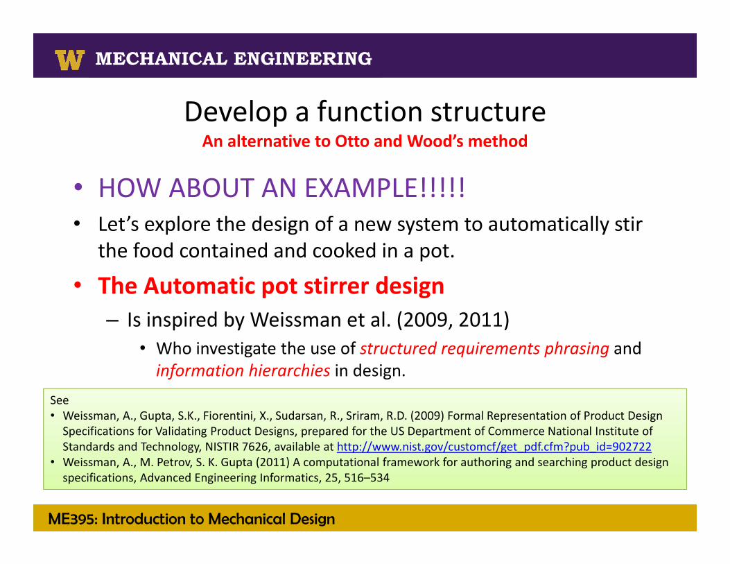
Develop a function structureAn alternative to Otto and Wood’s method
• HOW ABOUT AN EXAMPLE!!!!!• Let’s explore the design of a new system to automatically stir
the food contained and cooked in a pot.
• The Automatic pot stirrer design– Is inspired by Weissman et al. (2009, 2011)
• Who investigate the use of structured requirements phrasing and information hierarchies in design.
See • Weissman, A., Gupta, S.K., Fiorentini, X., Sudarsan, R., Sriram, R.D. (2009) Formal Representation of Product Design Specifications for Validating Product Designs, prepared for the US Department of Commerce National Institute of Standards and Technology, NISTIR 7626, available at http://www.nist.gov/customcf/get_pdf.cfm?pub_id=902722
• Weissman, A., M. Petrov, S. K. Gupta (2011) A computational framework for authoring and searching product design specifications, Advanced Engineering Informatics, 25, 516–534

ME395: Introduction to Mechanical Design
MECHANICAL ENGINEERING
Solid Fuels Processing Technologies
MECHANICAL ENGINEERING
From product research to design requirementsAutomatic pot stirrer design
• Product research– From Amazon
– To Patents– Codes and standards– Customer interview
The StirChef Handsfree Stirrer RoboStir by TelebrandsEzStir

ME395: Introduction to Mechanical Design
MECHANICAL ENGINEERINGExample customer reviews from AmazonGood• I don't have 30‐40 minutes to devote to one task. I bought a
StirChef and used it for the first time last night. It worked very well. The housing is a little bulky, but I just kept pouring ladles of broth past it and in the end had very good risotto while being able to cook the rest of the meal and pick up the house a little. This was great for a time‐challenged cook.
• I bought two of them five years ago and modified them to stir my 12 quart each caramel batches. I replaced the plastic paddle with a sheet of white 1/16th inch thick Teflon sheet. I replaced the arms with bent metal tongs and wired the battery leads to a 6 volt DC power supply. They have worked like a charm and never gets bogged down even when the caramel gets very thick. Early on when using the original plastic paddle it melted away into the caramel batch hence the Teflon sheet I use now.
Bad• Poorly constructed and does not do as designed/ piece of junk• Within just a few minutes of use, the plastic began to melt and
stain beyond recognition.• After about 4 minutes the flimsy plastic blades began to melt,
adding an interesting but unwanted taste to the vegetables. • Biggest problem I have with the unit (next to the 4 dead batteries
that it came with) is the speed at which it turns; the constant turn setting seems a little slow. I found that at the speed it turns, I needed to keep my heat at a slow medium or I got build‐up and scorching. Not a problem that you can't overcome, but lower temps mean longer cooking times.
• Ensure adequate power.
• Ensure product is reliable.
• Ensure parts do not melt.
• Operate up to 30‐40 minutes at a time.

ME395: Introduction to Mechanical Design
MECHANICAL ENGINEERING
Solid Fuels Processing Technologies
MECHANICAL ENGINEERING
From product research to design requirementsAutomatic pot stirrer design
• Product research– Patents
• The device shall not infringe on…. – US Patent 5863121: for the StirChef– US Patent 6026735 A: assembly includes U‐shaped device which provides heat (so not used on a stove) and stirring energy to pots with integrated stirrer (supplied).
– US Patent US 8376608 B2: Stirring apparatus with deflector that sits in the bottom of a pot.
– US Patent ???? for RoboStir by TELEBRANDS
ME395: Introduction to Mechanical Design
MECHANICAL ENGINEERING
Solid Fuels Processing Technologies
MECHANICAL ENGINEERING
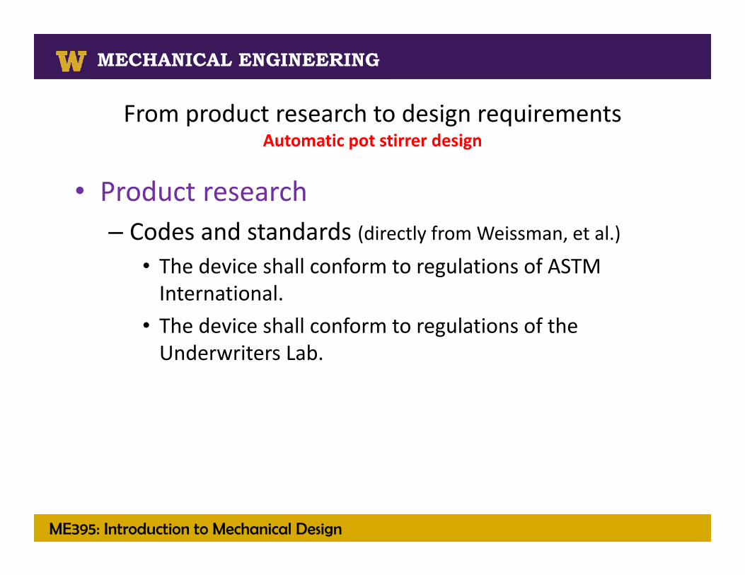
From product research to design requirementsAutomatic pot stirrer design
• Product research– Codes and standards (directly from Weissman, et al.)
• The device shall conform to regulations of ASTM International.
• The device shall conform to regulations of the Underwriters Lab.
ME395: Introduction to Mechanical Design
MECHANICAL ENGINEERING
Solid Fuels Processing Technologies
MECHANICAL ENGINEERING
From product research to design requirementsAutomatic pot stirrer design
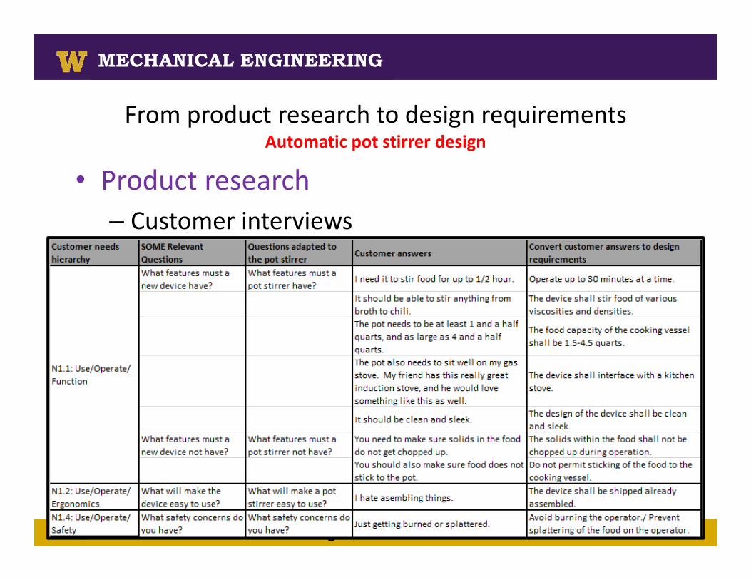
• Product research– Customer interviews

ME395: Introduction to Mechanical Design
MECHANICAL ENGINEERING
From product research to design requirementsAutomatic pot stirrer design
• Product research– Customer interviews

ME395: Introduction to Mechanical Design
MECHANICAL ENGINEERING
Solid Fuels Processing Technologies
MECHANICAL ENGINEERING
From product research to design requirementsAutomatic pot stirrer design
R1: Conduct Market ResearchR1.1: Conduct Market Research/ Patent Infringement• The device shall not infringe on US Patent 5863121.• The device shall not infringe on US Patent 6026735 A.• The device shall not infringe on US Patent 8376608 B2.• The device shall not infringe on US Patent for RoboStir by TELEBRANDS.R1.4: Conduct Market Research/ Cost• Minimize the purchase cost.R2: Design• The device shall conform to regulations of ASTM International.• The device shall conform to regulations of the Underwriters Lab.R3: Procure• Use standard parts and processes whenever possible.• Use purchased components and parts whenever possible. Covered elsewhere
Adapted from the Design Information
Database
ME395: Introduction to Mechanical Design
MECHANICAL ENGINEERING
Solid Fuels Processing Technologies
MECHANICAL ENGINEERING
From product research to design requirementsAutomatic pot stirrer design
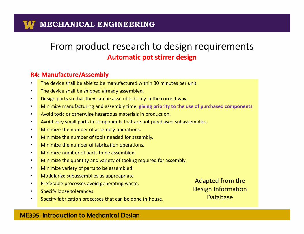
R4: Manufacture/Assembly• The device shall be able to be manufactured within 30 minutes per unit.• The device shall be shipped already assembled.• Design parts so that they can be assembled only in the correct way.• Minimize manufacturing and assembly time, giving priority to the use of purchased components.• Avoid toxic or otherwise hazardous materials in production.• Avoid very small parts in components that are not purchased subassemblies.• Minimize the number of assembly operations.• Minimize the number of tools needed for assembly.• Minimize the number of fabrication operations.• Minimize number of parts to be assembled.• Minimize the quantity and variety of tooling required for assembly.• Minimize variety of parts to be assembled.• Modularize subassemblies as approapriate• Preferable processes avoid generating waste.• Specify loose tolerances.• Specify fabrication processes that can be done in‐house.
Adapted from the Design Information
Database

ME395: Introduction to Mechanical Design
MECHANICAL ENGINEERING
Solid Fuels Processing Technologies
MECHANICAL ENGINEERING
From product research to design requirementsAutomatic pot stirrer design
R5: Test/Inspect• Design the product, its major subassemblies, and other components so that they
can be easily tested.R6: Ship/Transport• The device shall be able to endure a drop of X feet while not in operation.• Design minimizes the need for packagingR7: Warehouse• The device shall be able to be stacked up to 6 units high once packaged.R8: Display• The design of the device shall be clean and sleek.R9: Install
ME395: Introduction to Mechanical Design
MECHANICAL ENGINEERING
Solid Fuels Processing Technologies
MECHANICAL ENGINEERING
From product research to design requirementsAutomatic pot stirrer design
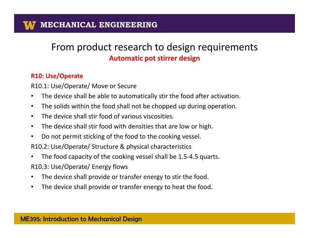
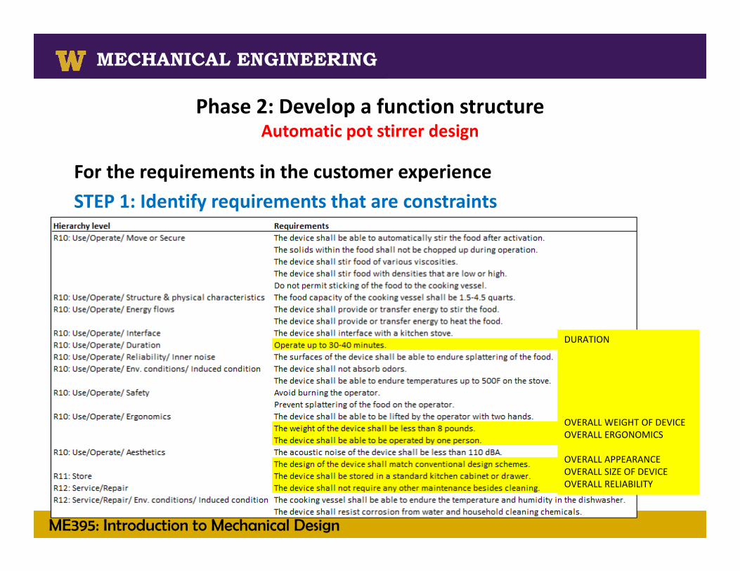
R10: Use/Operate R10.1: Use/Operate/ Move or Secure• The device shall be able to automatically stir the food after activation.• The solids within the food shall not be chopped up during operation.• The device shall stir food of various viscosities.• The device shall stir food with densities that are low or high.• Do not permit sticking of the food to the cooking vessel.R10.2: Use/Operate/ Structure & physical characteristics• The food capacity of the cooking vessel shall be 1.5‐4.5 quarts.R10.3: Use/Operate/ Energy flows• The device shall provide or transfer energy to stir the food.• The device shall provide or transfer energy to heat the food.

ME395: Introduction to Mechanical Design
MECHANICAL ENGINEERING
Solid Fuels Processing Technologies
MECHANICAL ENGINEERING
From product research to design requirementsAutomatic pot stirrer design
R10: Use/Operate R10.4: Use/Operate/ Interface• The device shall interface with a kitchen stove.R10.5: Use/Operate/ Duration• Operate up to 30‐40 minutes.R10.6: Use/Operate/ Reliability/ Inner noise• The surfaces of the device shall be able to endure splattering of the food.• Maximize product reliability.R10.7: Use/Operate/ Env. conditions/ Induced condition• The device shall not absorb odors.• The device shall be able to endure temperatures up to 500F on the stove.
Adapted from the Design Information
Database
ME395: Introduction to Mechanical Design
MECHANICAL ENGINEERING
Solid Fuels Processing Technologies
MECHANICAL ENGINEERING
From product research to design requirementsAutomatic pot stirrer design
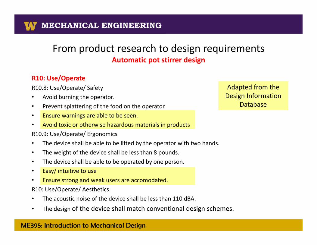
R10: Use/Operate R10.8: Use/Operate/ Safety• Avoid burning the operator.• Prevent splattering of the food on the operator.• Ensure warnings are able to be seen.• Avoid toxic or otherwise hazardous materials in productsR10.9: Use/Operate/ Ergonomics• The device shall be able to be lifted by the operator with two hands.• The weight of the device shall be less than 8 pounds.• The device shall be able to be operated by one person.• Easy/ intuitive to use• Ensure strong and weak users are accomodated.R10: Use/Operate/ Aesthetics• The acoustic noise of the device shall be less than 110 dBA.
• The design of the device shall match conventional design schemes.
Adapted from the Design Information
Database

ME395: Introduction to Mechanical Design
MECHANICAL ENGINEERING
Solid Fuels Processing Technologies
MECHANICAL ENGINEERING
From product research to design requirementsAutomatic pot stirrer design
R11: Store• The device shall be stored in a standard kitchen cabinet or drawer.R12: Service/Repair• The device shall not require any other maintenance besides cleaning.• The cooking vessel shall be able to endure the temperature and humidity in the dishwasher.• The device shall resist corrosion from water and household cleaning chemicals.R13: UpgradeR14: Dismantle• The device shall be able to be dismantled using a phillips screwdriver for purposes of
recycling.R15: Recycle• The device shall be made from fully recyclable materials.• The device shall be made from recycled materials.• Label parts to instruct for recycling. R16: Dispose• Use of environmentally hazardous materials in the device shall be prohibited.
Adapted from the Design Information
Database
ME395: Introduction to Mechanical Design
MECHANICAL ENGINEERING
Solid Fuels Processing Technologies
MECHANICAL ENGINEERING
From design requirements to subfunctionsAutomatic pot stirrer design
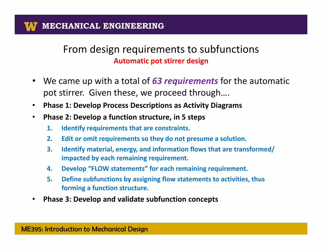
• We came up with a total of 63 requirements for the automatic pot stirrer. Given these, we proceed through….
• Phase 1: Develop Process Descriptions as Activity Diagrams• Phase 2: Develop a function structure, in 5 steps
1. Identify requirements that are constraints.2. Edit or omit requirements so they do not presume a solution.3. Identify material, energy, and information flows that are transformed/
impacted by each remaining requirement.4. Develop “FLOW statements” for each remaining requirement.5. Define subfunctions by assigning flow statements to activities, thus
forming a function structure.
• Phase 3: Develop and validate subfunction concepts
ME395: Introduction to Mechanical Design
MECHANICAL ENGINEERING
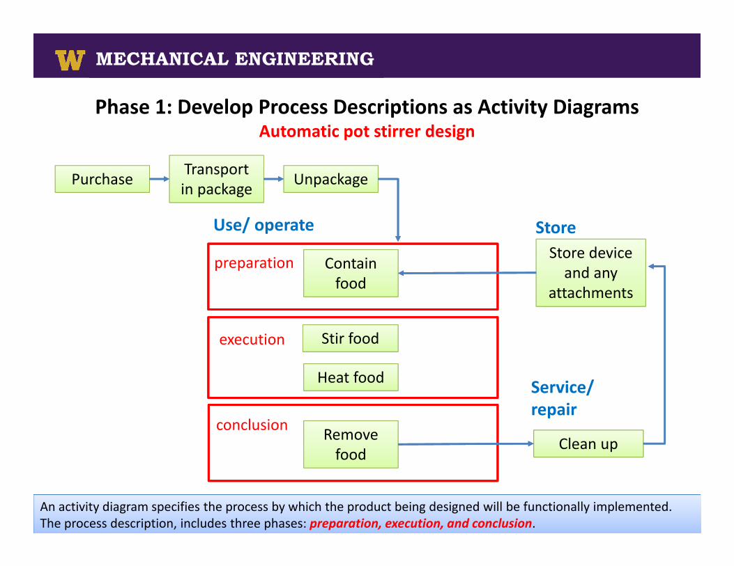
Phase 1: Develop Process Descriptions as Activity DiagramsAutomatic pot stirrer design
Contain food
Heat food
Remove food
Clean up
Store device and any
attachments
preparation
execution
conclusion
Use/ operate
Service/ repair
Store
Stir food
Purchase Transport in package Unpackage
An activity diagram specifies the process by which the product being designed will be functionally implemented. The process description, includes three phases: preparation, execution, and conclusion.
ME395: Introduction to Mechanical Design
MECHANICAL ENGINEERING
Solid Fuels Processing Technologies
MECHANICAL ENGINEERING
Phase 2: Develop a function structureAutomatic pot stirrer design
For the requirements in the customer experienceSTEP 1: Identify requirements that are constraints
DURATION
OVERALL WEIGHT OF DEVICEOVERALL ERGONOMICS
OVERALL APPEARANCEOVERALL SIZE OF DEVICEOVERALL RELIABILITY

ME395: Introduction to Mechanical Design
MECHANICAL ENGINEERING
Solid Fuels Processing Technologies
MECHANICAL ENGINEERING
Phase 2: Develop a function structureAutomatic pot stirrer design
STEP 2: Edit or omit requirements so they do not presume a solution– Remember the rule for developing requirements that everyone agreed
upon…. Describe “what” not “how”
PRESUMES THE USE OF A STOVE
Presumes a cooking vessel will be provided with the product
ME395: Introduction to Mechanical Design
MECHANICAL ENGINEERING
Solid Fuels Processing Technologies
MECHANICAL ENGINEERING
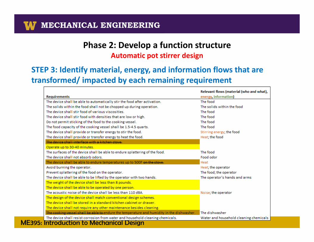
Phase 2: Develop a function structureAutomatic pot stirrer design
STEP 3: Identify material, energy, and information flows that are transformed/ impacted by each remaining requirement

ME395: Introduction to Mechanical Design
MECHANICAL ENGINEERING
Solid Fuels Processing Technologies
MECHANICAL ENGINEERING
Phase 2: Develop a function structureAutomatic pot stirrer design
STEP 4: Develop “FLOW statements” for each remaining requirement,noting that you MUST mention ALL FLOWS identified in step 3 and you CAN add quantifying criteria (e.g., withstand a temperature of 500F; withstand a drop from 5 ft) if they are not already in the requirement.
ME395: Introduction to Mechanical Design
MECHANICAL ENGINEERING
Solid Fuels Processing Technologies
MECHANICAL ENGINEERING
Phase 2: Develop a function structureAutomatic pot stirrer design
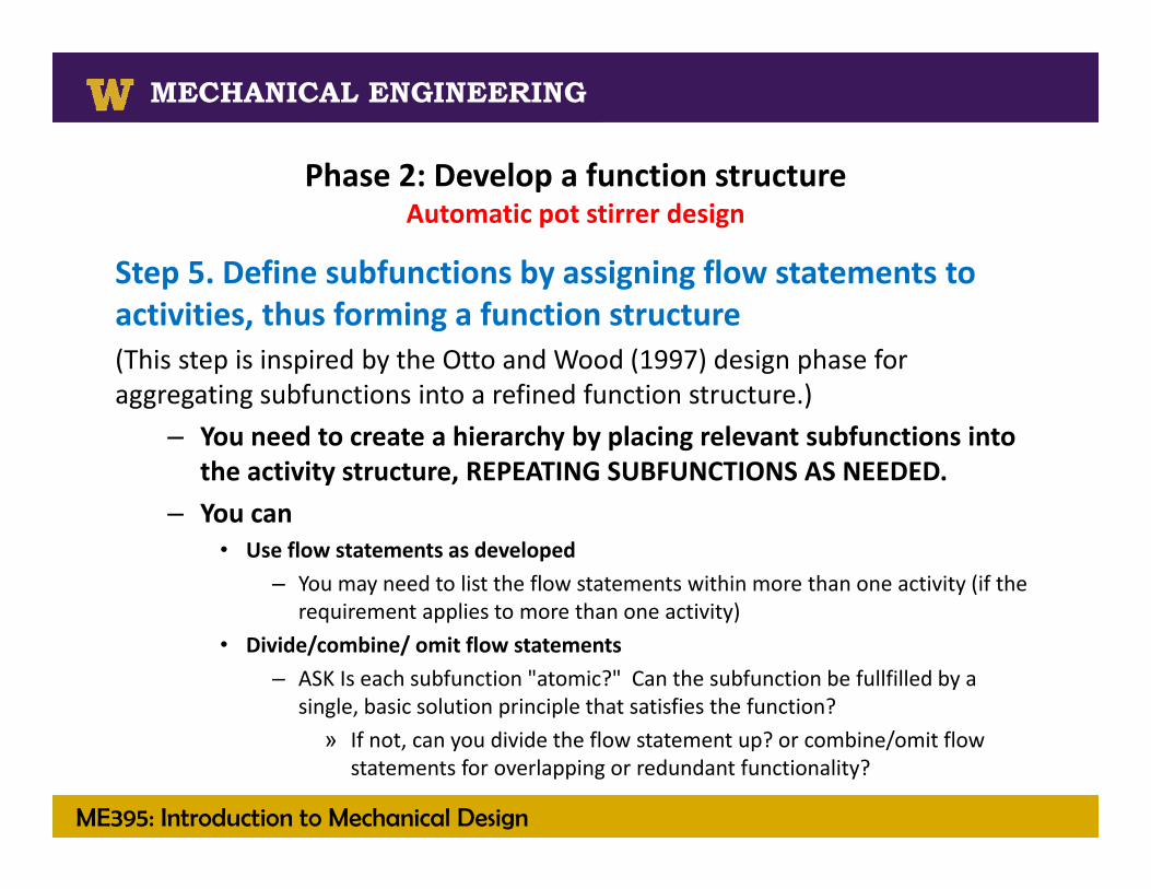
Step 5. Define subfunctions by assigning flow statements to activities, thus forming a function structure(This step is inspired by the Otto and Wood (1997) design phase for aggregating subfunctions into a refined function structure.)
– You need to create a hierarchy by placing relevant subfunctions into the activity structure, REPEATING SUBFUNCTIONS AS NEEDED.
– You can• Use flow statements as developed
– You may need to list the flow statements within more than one activity (if the requirement applies to more than one activity)
• Divide/combine/ omit flow statements– ASK Is each subfunction "atomic?" Can the subfunction be fullfilled by a
single, basic solution principle that satisfies the function?» If not, can you divide the flow statement up? or combine/omit flow
statements for overlapping or redundant functionality?

ME395: Introduction to Mechanical Design
MECHANICAL ENGINEERING
Step 5. Define subfunctions by assigning flow statements to activities, thus forming a function structure
• Use flow statements as developed, multiple times if needed
• Divide/combine/ omit flow statements
And notice the activity “store” seems to be missing…… because the related requirements have been designated as constraints.
Activity diagram

Functional DecompositionThe process
• So let’s compare the functional decomposition processes:• Phase 1: Develop process descriptions as activity diagrams• Phase 2: Develop a function structure
• Phase 3: Develop and validate subfunction concepts
Using the alternative to Otto and Wood’s method1. Identify requirements that are constraints.2. Edit or omit requirements so they do not presume a solution.3. Identify material, energy, and information flows that are
transformed/ impacted by each remaining requirement.4. Develop “FLOW statements” for each remaining requirement.5. Define subfunctions by assigning flow statements to activities,
thus forming a function structure.
Using Otto and Wood’s method1. Formulate sub functions through
black box modeling and task listing.
2. Aggregate subfunctions into a refined function structure.
Using Otto and Wood’s method1. Validate the functional
decomposition (ensuring the defined subfunctions cover all of the requirements)
2. Establish and identify product architecture and assemblies (using a morphological chart)
Using the alternative to Otto and Wood’s method1. Use the subfunction structure to prepare a morphological
chart.2. OMIT subfunction concepts on the basis of the life cycle
requirements and constraints.
But what is a morphological chart?

ME395: Introduction to Mechanical Design
MECHANICAL ENGINEERING
Solid Fuels Processing Technologies
MECHANICAL ENGINEERING
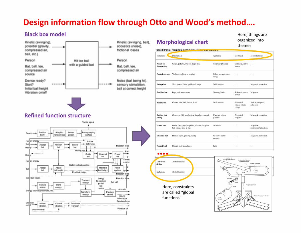
Phase 3: Establish and identify product architecture and assemblies
• Given the subfunctions defined, a Morphological Chart is a matrix which catalogs combinations of alternative subfunctionconcepts. Sub function concepts
(1) (2) (3) (4) Functions and subfunctions 1. Level 1 purchase 2. Level 1 transport in package 3. Level 1 unpackage 4. Level 1 loosen/ tighten screws 4.1 Level 2 pick up and hold 4.1.1 Level 3 grip 4.1.2 Level 3 house electronics 4.1.2 Level 3 safety/off switch 4.2 Level 2 uninstall & install bits 4.2.1 Level 3 accept and reject bit 4.2.2 Level 3 secure bit 4.3 Level 2 secure screw 4.4 Level 2 rotate screw 4.4.1 Level 3 supply power 4.4.1.1 Level 4 use energy … 4.4.1.2 Level 4 generate torque 4.4.2 Level 3 apply torque … 4.5 Level 2 put down screwdriver 4.5.1 Level 3 recharge 4.5.2 Level 3 store bits 4.5.3 Level 3 store screws
• THE ROWS LIST SUBFUNCTION CONCEPTS
• THE COLUMNS (within a theme), MEAN NOTHING.
The morphological chart therefore depicts MANY SUBFUNCTION COMBINATIONS and therefore many possible superior design concepts.
Battery Electrical inlet ? ?
….
Black box model
Refined function structure
Morphological chart
Here, constraints are called “global functions”
Design information flow through Otto and Wood’s method….Here, things are organized into themes

QUESTION inspired by the customer experience hierarchy: What features must a pot stirrer not have?
RESPONSE: You should also make sure food does not stick to the pot.
Develop a list of design requirementsR10: Use/Operate/ Move or Secure‐ Do not permit sticking of the food to the cooking vessel.
Develop a function structure• Not a constraint and does not presume a solution• Relevant flows: food (material)• Flow statement: Avoid sticking food
Develop and validate subfunction conceptsUse the subfunction structure to prepare a morphological chart and OMIT subfunction concepts on the basis of life cycle requirements and constraints
Contain food
Heat food
Remove food
preparation
execution
conclusion
Develop Process Descriptions as Activity Diagrams: Use/ operate
Stir food
Design information flow the alternative to Otto and Wood’s method….
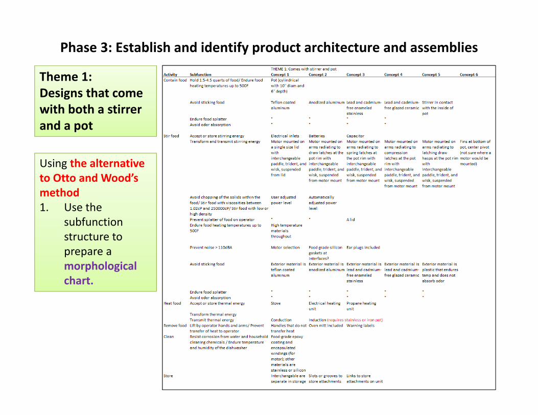
Theme 1:Designs that come with both a stirrer and a pot
Phase 3: Establish and identify product architecture and assemblies
Using the alternative to Otto and Wood’s method1. Use the
subfunctionstructure to prepare a morphological chart.
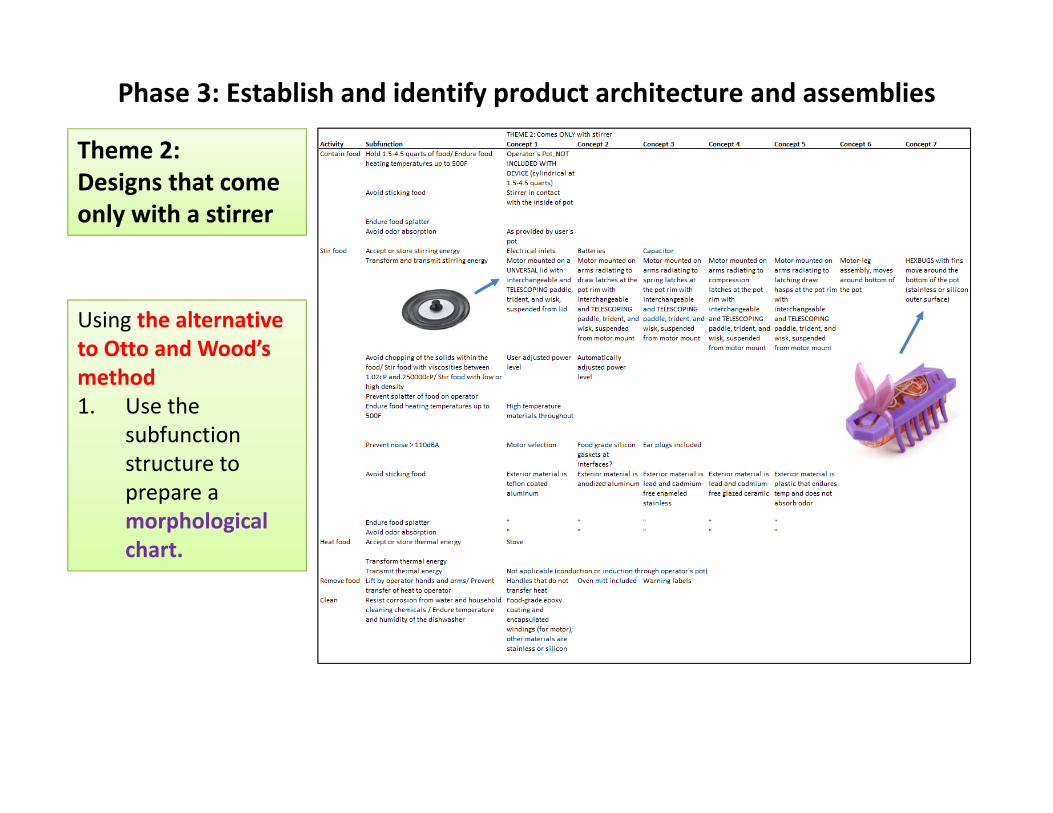
Theme 2:Designs that come only with a stirrer
Phase 3: Establish and identify product architecture and assemblies
Using the alternative to Otto and Wood’s method1. Use the
subfunctionstructure to prepare a morphological chart.

Theme 2:Designs that come only with a stirrer
Radiating arms appear to infringe on US Patent 5863121
This might need to be licensed
Likely infringes on the RoboStirby TELEBRANDS.
Teflon is suspected to be hazardous
Using the alternative to Otto and Wood’s method2. Omit concepts based on life cycle reqs. and constraints
Phase 3: Establish and identify product architecture and assemblies

ME395: Introduction to Mechanical Design
MECHANICAL ENGINEERING
Solid Fuels Processing Technologies
MECHANICAL ENGINEERING
Concept Generation: morphological ideas• There are some resources available for generating morphological ideas.– Some tables have been developed
From Magrab, E.B., 1997, Integrated Product and Process Design and Development: The Product Realization Process.
Concepts for clamping Concepts for rotary motion

ME395: Introduction to Mechanical Design
MECHANICAL ENGINEERING
Concept Generation: morphological ideas
From http://www.invention‐machine.comWatch for redirects, company was bought by HIS, and it seems they call the tool IHS Goldfire
There is software
ME395: Introduction to Mechanical Design
MECHANICAL ENGINEERING
Solid Fuels Processing Technologies
MECHANICAL ENGINEERING
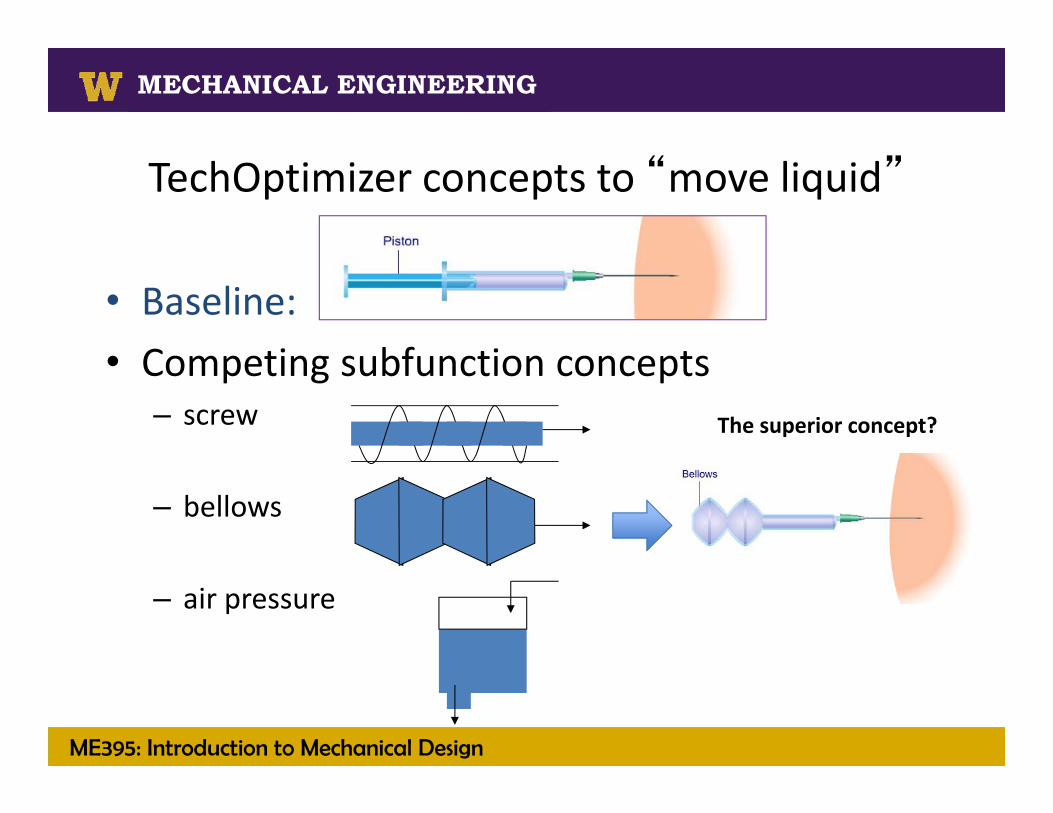
TechOptimizer concepts to “move liquid”
• Baseline: • Competing subfunction concepts
– screw
– bellows
– air pressure
The superior concept?
ME395: Introduction to Mechanical Design
MECHANICAL ENGINEERING
Solid Fuels Processing Technologies
MECHANICAL ENGINEERING
Concept Generation: morphological ideas
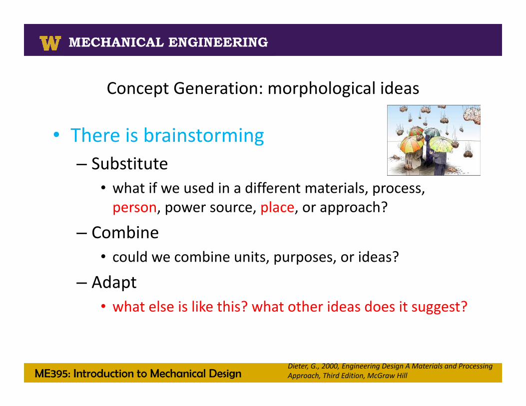
• There is brainstorming– Substitute
• what if we used in a different materials, process, person, power source, place, or approach?
– Combine• could we combine units, purposes, or ideas?
– Adapt• what else is like this? what other ideas does it suggest?
Dieter, G., 2000, Engineering Design A Materials and Processing Approach, Third Edition, McGraw Hill
ME395: Introduction to Mechanical Design
MECHANICAL ENGINEERING
Solid Fuels Processing Technologies
MECHANICAL ENGINEERING
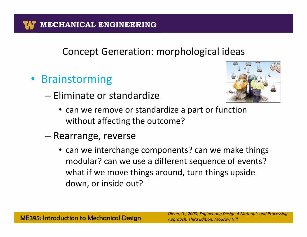
Concept Generation: morphological ideas
• Brainstorming– Eliminate or standardize
• can we remove or standardize a part or function without affecting the outcome?
– Rearrange, reverse• can we interchange components? can we make things modular? can we use a different sequence of events? what if we move things around, turn things upside down, or inside out?
Dieter, G., 2000, Engineering Design A Materials and Processing Approach, Third Edition, McGraw Hill
ME395: Introduction to Mechanical Design
MECHANICAL ENGINEERING
Solid Fuels Processing Technologies
MECHANICAL ENGINEERING
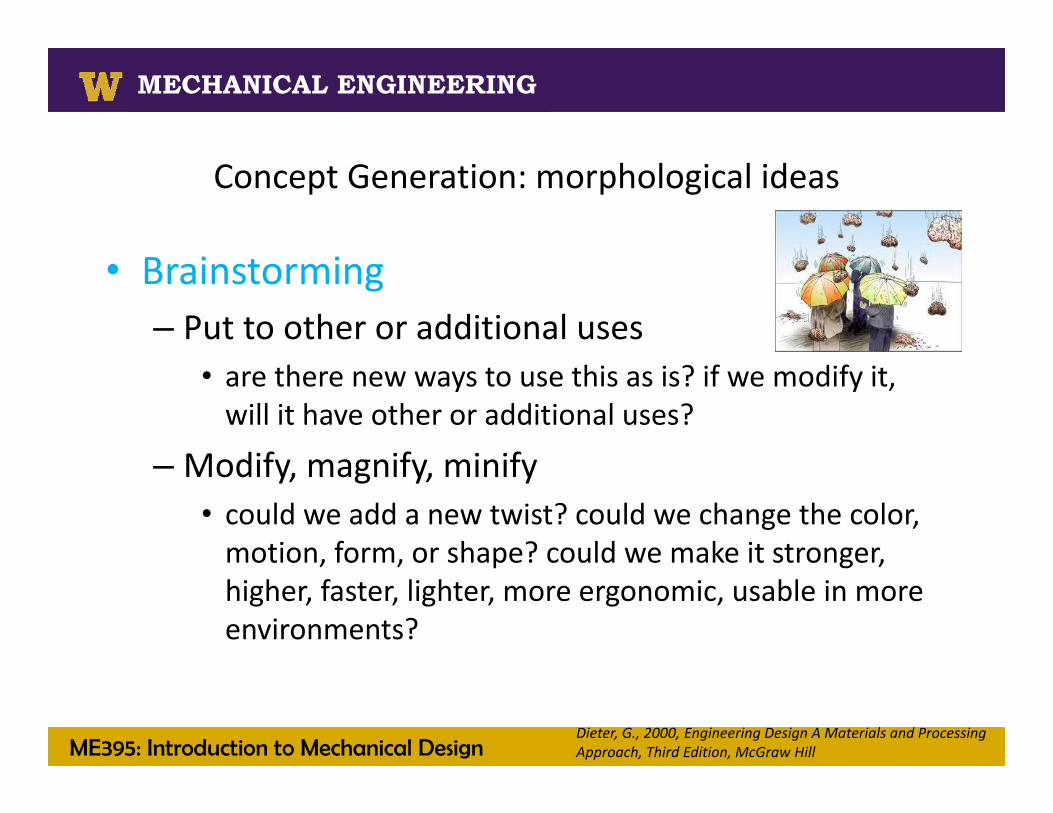
Concept Generation: morphological ideas
• Brainstorming– Put to other or additional uses
• are there new ways to use this as is? if we modify it, will it have other or additional uses?
– Modify, magnify, minify• could we add a new twist? could we change the color, motion, form, or shape? could we make it stronger, higher, faster, lighter, more ergonomic, usable in more environments?
Dieter, G., 2000, Engineering Design A Materials and Processing Approach, Third Edition, McGraw Hill
ME395: Introduction to Mechanical Design
MECHANICAL ENGINEERING
Solid Fuels Processing Technologies
MECHANICAL ENGINEERING
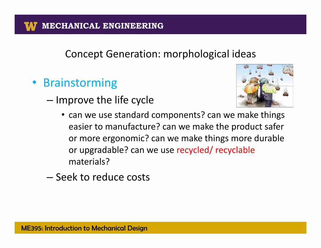
Concept Generation: morphological ideas
• Brainstorming – Improve the life cycle
• can we use standard components? can we make things easier to manufacture? can we make the product safer or more ergonomic? can we make things more durable or upgradable? can we use recycled/ recyclable materials?
– Seek to reduce costs

ME395: Introduction to Mechanical Design
MECHANICAL ENGINEERING
Solid Fuels Processing Technologies
MECHANICAL ENGINEERING
Functional DecompositionThe process
• Phase 1: Develop process descriptions as activity diagrams• Phase 2: Develop a function structure
• Phase 3: Develop and validate subfunction concepts
Using the alternative to Otto and Wood’s method1. Identify requirements that are constraints.2. Edit or omit requirements so they do not presume a solution.3. Identify material, energy, and information flows that are
transformed/ impacted by each remaining requirement.4. Develop “FLOW statements” for each remaining requirement.5. Define subfunctions by assigning flow statements to activities,
thus forming a function structure.
Using Otto and Wood’s method1. Formulate sub functions through
black box modeling and task listing.
2. Aggregate subfunctions into a refined function structure.
Using Otto and Wood’s method1. Validate the functional
decomposition (ensuring the defined subfunctions cover all of the requirements)
2. Establish and identify product architecture and assemblies (using a morphological chart)
Using the alternative to Otto and Wood’s method1. Use the subfunction structure to prepare a morphological
chart.2. OMIT subfunction concepts on the basis of the life cycle
requirements and constraints.
ME395: Introduction to Mechanical Design
MECHANICAL ENGINEERING
Solid Fuels Processing Technologies
MECHANICAL ENGINEERING
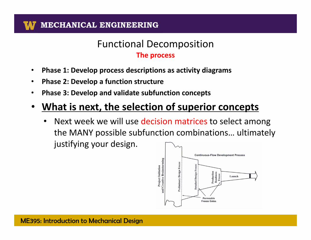
Functional DecompositionThe process
• Phase 1: Develop process descriptions as activity diagrams• Phase 2: Develop a function structure• Phase 3: Develop and validate subfunction concepts
• What is next, the selection of superior concepts• Next week we will use decision matrices to select among
the MANY possible subfunction combinations… ultimately justifying your design.