4- earthquake resistant design according to 1994...
TRANSCRIPT

94
4- Earthquake Resistant Design According To 1994 UBC
The Static Lateral Force Procedure
4-1 Applicability: The static lateral force procedure may be used for the following structures: A. All structures, regular or irregular (see Tables 4.1.a and
4.1.b), in seismic zone no. 1 and in standard occupancy- structures in seismic zone no. 2 (see Table 4.2 for zone classification and Table 4.4 for occupancy factors).
B. Regular structures under 73 m in height with lateral force resistance provided by systems given in Tables 4.5.a and 4.5.b except for structures located in soil profile type S4 which have a period greater than 0.70 sec. (see Table 4.3 for soil profiles).
C. Irregular structures not more than five stories or 20 m in height.
D. Structures having a flexible upper portion supported on a rigid lower portion where both portions of the structure considered separately can be classified as being regular, the average story stiffness of the lower portion is at least ten times the average stiffness of the upper portion and the period of the entire structure is not greater than 1.10 times the period of the upper portion considered as a separate structure fixed at the base.

95
Regular Structures:
Regular structures are structures having no significant physical discontinuities in plan or vertical configuration or in their lateral force resisting.
Irregular Structures:
Irregular structures are structures having significant physical discontinuities in configuration or in their lateral force resisting systems (See Table 4.1.a and 4.1.b for detailed description of such structures).
Load Combinations:
The total design forces are calculated from the following cases of loading.
)(4.1 ELDU ±+= (4.1)
EDU 4.19.0 ±= (4.2)
Where
U = Ultimate design force D = Service dead load L = Service live load E = Service earthquake load

96
Concept of Method:
• The 1994 UBC equivalent static method considers only horizontal movement and neglects effects of vertical ground movement.
• Statically models the inertial effects using Newton’s 2nd Law of Motion given by Eqn. (4.3).
aMF = (4.3) Where F = resulting force on structure M = building mass a = acceleration of ground
But g
WM =
And Eqn. (4.3) can be written as
=
gaWF (4.4)
Minimum Design Lateral Forces:
The design seismic forces may be assumed to act non-concurrently in the direction of each principal axis of the structure.
The total design base shear in a given direction is to be determined from the following Eqn.
97
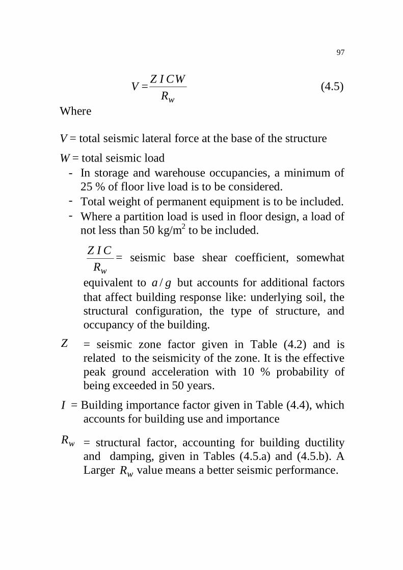
wRWCIZV = (4.5)
Where V= total seismic lateral force at the base of the structure
W= total seismic load - In storage and warehouse occupancies, a minimum of
25 % of floor live load is to be considered. - Total weight of permanent equipment is to be included. - Where a partition load is used in floor design, a load of
not less than 50 kg/m2 to be included.
wRCIZ = seismic base shear coefficient, somewhat
equivalent to ga / but accounts for additional factors that affect building response like: underlying soil, the structural configuration, the type of structure, and occupancy of the building.
Z = seismic zone factor given in Table (4.2) and is related to the seismicity of the zone. It is the effective peak ground acceleration with 10 % probability of being exceeded in 50 years.
I = Building importance factor given in Table (4.4), which accounts for building use and importance
wR = structural factor, accounting for building ductility and damping, given in Tables (4.5.a) and (4.5.b). A Larger wR value means a better seismic performance.

98
Ductility = ability to deform in the inelastic range prior to fracture
Damping = resistance to motion provided by material friction
C = dynamic response value, and accounts for how the building and soil can amplify the basic ground acceleration
( ) wRCT
SC 075.075.225.13/2 ≥≥= (4.6)
S = site Coefficient depending on the soil characteristics given in Table (4.3).
T = structural fundamental period in seconds in the direction under consideration evaluated from the following equations.
For moment-resisting frames,
( ) 4/3073.0 nhT = (4.7)
For shear walls, ( )
c
nA
hT
4/30743.0= (4.8)
For other buildings,
( ) 4/3048.0 nhT = (4.9)
Where
nh = total height of building in meters cA = effective cross-sectional area of shear walls
99
+∑=
2
2.0n
eic h
DAA 9.0/ ≤ne hD (4.10)
iA = cross-sectional area of individual shear walls in the
direction of loads in m2
eD = length of each shear wall in the direction of loads
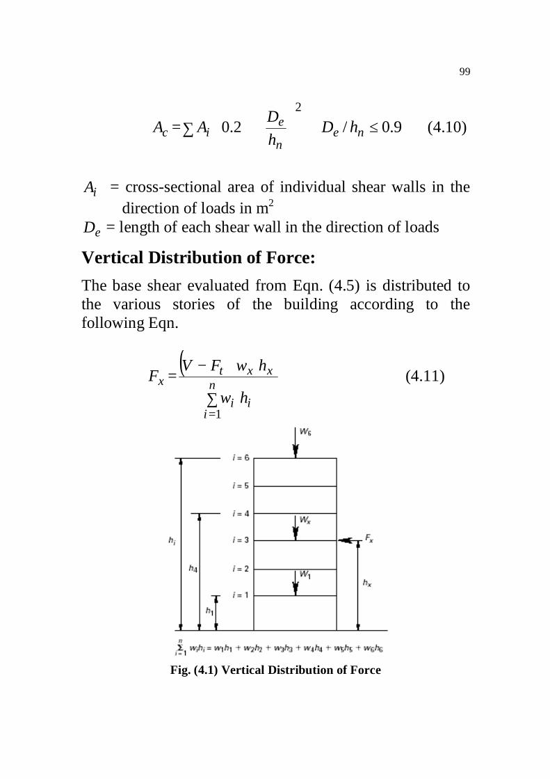
Vertical Distribution of Force:
The base shear evaluated from Eqn. (4.5) is distributed to the various stories of the building according to the following Eqn.
( )
∑
−=
=
n
iii
xxtx
hw
hwFVF
1
(4.11)
Fig. (4.1) Vertical Distribution of Force

100
Where
0=tF for 7.0≤T sec.
VVTFt 25.007.0 ≤= for 7.0>T sec. The shear force at each story is given by Eqn. (4.12)
∑+==
n
xiitx FFV (4.12)
Where
n = number of stories above the base of the building tF = the portion of the base shear, concentrated at the top
of the structure to account for whiplash effects xni FFF ,, = lateral forces applied at levels xorni ,, ,
respectively xni hhh ,, = height above the base to levels xorni ,, ,
respectively xV = design shear in story x
Horizontal Distribution of Force:
The design story shear in any direction xV , is distributed to the various elements of the lateral force-resisting system in proportion to their rigidities.
Horizontal Torsional Moment:
To account for the uncertainties in locations of loads, the mass at each level is assumed to be displaced from the

101
calculated center of mass in each direction a distance equal to 5 % of the building dimension at that level perpendicular to the direction of the force under consideration. The torsional design moment at a given story is given by moment resulting from eccentricities between applied design lateral forces applied through each story’s center of mass at levels above the story and the center of stiffness of the vertical elements of the story, in addition to the accidental torsion.
Overturning Moments:
The overturning moments are to be determined at each level of the structure.
The overturning moment xM at level x is given by Eqn. (4.13).
( ) ( )∑ −+−=+=
n
xixiixntx hhFhhFM
1 (4.13)
Overturning moments are distributed to the various elements of the vertical lateral force-resisting system in proportion to their rigidities.
∆−P Effects:
The resulting member forces, moments and story drifts induced by ∆−P effects are to be considered in the evaluation of overall structural frame stability. ∆−P effects are neglected when the ratio given by Eqn. (4.14) is
.1.0≤

102
xx
xx
primary
ondary
hVP
MM ∆
=sec (4.14)
xP = total seismic weight at level x and above ∆ = drift of story x
xV = shear force of story x xh = height of story x
In seismic zones no. 3 and 4, ∆−P effects are neglected when the story drift wR/02.0≤ times the story height.
Design of Cantilevers:
Horizontal cantilever components are to be designed for a net upward force of pw2.0 , where pw is the weight of the cantilevered element.
Story Drift Limitations:
Story drift is the displacement of one level relative to the level above or below due to the design lateral forces. Calculated drift is to include translational and torsional deformations. Calculated story drift shall not exceed
wR/04.0 or 005.0 times the story height for buildings with periods 7.0< second. For structures with periods 7.0≥ sec., the calculated story drift is not to exceed wR/03.0 or 004.0 the story height.
Design of Diaphragms:
Floor and roof diaphragms are to be designed to resist the forces determined from the following formula

103
pxn
xii
n
xiit
px ww
FFF
∑
∑+=
=
= (4.15)
The force pxF need not exceed 0.75 pxwIZ , but shall not be less than 0.35 pxwIZ Where
pxw = weight of the diaphragm at level x
pxF = diaphragm lateral design force at level x
104
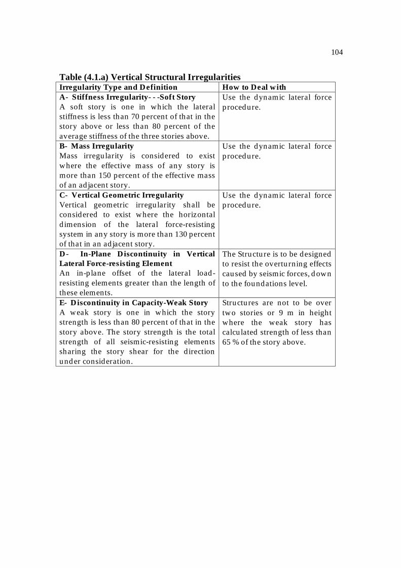
Table (4.1.a) Vertical Structural Irregularities Irregularity Type and Definition How to Deal with A- Stiffness Irregularity- - -Soft Story A soft story is one in which the lateral stiffness is less than 70 percent of that in the story above or less than 80 percent of the average stiffness of the three stories above.
Use the dynamic lateral force procedure.
B- Mass Irregularity Mass irregularity is considered to exist where the effective mass of any story is more than 150 percent of the effective mass of an adjacent story.
Use the dynamic lateral force procedure.
C- Vertical Geometric Irregularity Vertical geometric irregularity shall be considered to exist where the horizontal dimension of the lateral force-resisting system in any story is more than 130 percent of that in an adjacent story.
Use the dynamic lateral force procedure.
D- In-Plane Discontinuity in Vertical Lateral Force-resisting Element An in-plane offset of the lateral load-resisting elements greater than the length of these elements.
The Structure is to be designed to resist the overturning effects caused by seismic forces, down to the foundations level.
E- Discontinuity in Capacity-Weak Story A weak story is one in which the story strength is less than 80 percent of that in the story above. The story strength is the total strength of all seismic-resisting elements sharing the story shear for the direction under consideration.
Structures are not to be over two stories or 9 m in height where the weak story has calculated strength of less than 65 % of the story above.

105
Vertical Irregularities
106
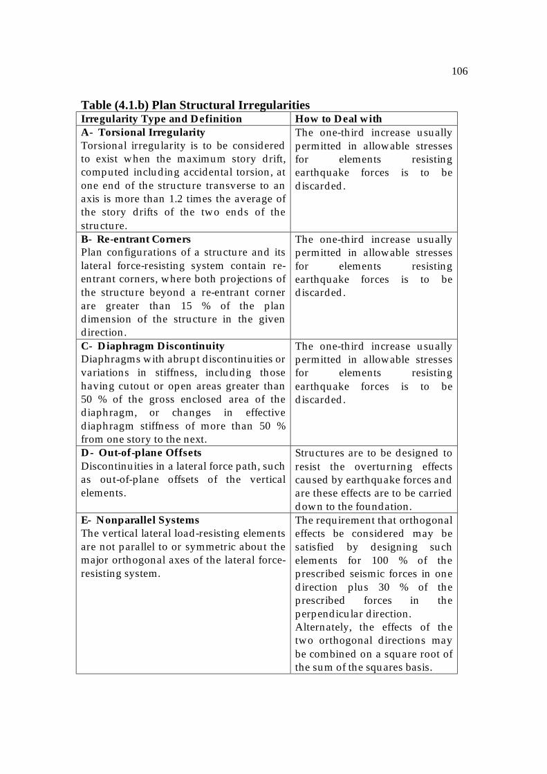
Table (4.1.b) Plan Structural Irregularities Irregularity Type and Definition How to Deal with A- Torsional Irregularity Torsional irregularity is to be considered to exist when the maximum story drift, computed including accidental torsion, at one end of the structure transverse to an axis is more than 1.2 times the average of the story drifts of the two ends of the structure.
The one-third increase usually permitted in allowable stresses for elements resisting earthquake forces is to be discarded.
B- Re-entrant Corners Plan configurations of a structure and its lateral force-resisting system contain re-entrant corners, where both projections of the structure beyond a re-entrant corner are greater than 15 % of the plan dimension of the structure in the given direction.
The one-third increase usually permitted in allowable stresses for elements resisting earthquake forces is to be discarded.
C- Diaphragm Discontinuity Diaphragms with abrupt discontinuities or variations in stiffness, including those having cutout or open areas greater than 50 % of the gross enclosed area of the diaphragm, or changes in effective diaphragm stiffness of more than 50 % from one story to the next.
The one-third increase usually permitted in allowable stresses for elements resisting earthquake forces is to be discarded.
D- Out-of-plane Offsets Discontinuities in a lateral force path, such as out-of-plane offsets of the vertical elements.
Structures are to be designed to resist the overturning effects caused by earthquake forces and are these effects are to be carried down to the foundation.
E- Nonparallel Systems The vertical lateral load-resisting elements are not parallel to or symmetric about the major orthogonal axes of the lateral force-resisting system.
The requirement that orthogonal effects be considered may be satisfied by designing such elements for 100 % of the prescribed seismic forces in one direction plus 30 % of the prescribed forces in the perpendicular direction. Alternately, the effects of the two orthogonal directions may be combined on a square root of the sum of the squares basis.

107

108
Table (4.2) Seismic Zone Factor
Zone 1 2A 2B 3 4 Z 0.075 0.15 0.20 0.30 0.40
Table (4.3) Site Coefficients
Type Description S Factor S1 - Rock-like material characterized by a shear wave
velocity greater than 750 m/s or by other means of classification. - Stiff or dense soil condition where the soil depth is less than 60 m.
1.0
S2 A soil profile with dense or stiff soil conditions, where the soil depth exceeds 60 m.
1.20
S3 A soil profile 20 m or more in depth and containing more than 6 m of soft to medium stiff clay but not more than 12 m of soft clay.
1.50
S4 A soil profile containing more than 12 m of soft clay characterized by a shear wave velocity less than 150 m/s.
2.0
Table (4.4) Occupancy Importance Factors Occupancy Category Functions of Structure Importance
Factor I Essential Facilities Hospitals, fire stations, police
stations, water tanks, garages, shelters, disaster control centers, and communications centers.
1.25
Hazardous Facilities Structures containing toxic, atomic, and explosive substances.
1.25
Special Occupancy Public assembly, schools, jails, power-generating stations.
1.0
Standard Occupancy Structures not listed above. 1.0

109
Table (4.5.a) Structural Factors (building structures) Basic Structural
System Lateral Load-Resisting System Rw Height (m)
Zones 3 & 4 Building Frame
Shear Walls (without vertical loads)
Shear Walls (with vertical loads) 8 6
73 73
Moment-Resisting Frame
SMRF IMRF OMRF
12 8 5
No Limit Not Used Not Used
Dual Systems Shear Walls + SMRF Shear Walls + IMRF
12 9
No Limit 48
Table (4.5.b) Structural Factor (nonbuilding structures)
No. Structure Type Rw
1- Tanks, vessels or pressurized spheres on braced or unbraced legs.
3
2- Cast-in-place concrete soils and chimneys having walls continuous to the foundation.
5
3- Inverted pendulum-type structures. 3 4- Cooling towers. 5

110

111
7x3
= 21
m
Example 1: A seven-story building frame system (residential) with shear walls has the dimensions shown in the figure. The total sustained dead load is 800 kg/m2. This building is located in Gaza Strip and lies on top of a deep clayey deposit. Eight shear walls, each 3 m long and 0.2 m thick are used as a lateral force resisting system. Determine the seismic loads at the floor levels of the building in a direction perpendicular to axis 1-1, 2-2, 3-3, and 4-4 using the 1994 UBC.
A B
C D
E F G H
6m 6m 6m
4.5m
4.
5m
4.5m
4.
5m
1
1
2
2
3
3
4
4

112
Solution: 8R,0.2S ,1I ,075.0Z w ====
Weight of floor = ( )( ) tons2.25918188.0 = Total seismic weight = ( ) tons4.181472.259 = Building natural period, T
( )c
n
AhT
43
0743.0=
+=∑
2
2.0n
eic h
DAA 9.0/ ≤ne hD
( )( ) 24
1
2
529.02132.02.03 mA
ic =
+=∑
= , 9.0142.0
213
<=
O.K ( ) ( ) sec002.1
529.0210743.00743.0
4/34/3
===c
n
AhT
( )( )
75.2sec5.2002.1
225.1T
S25.1C 3/23/2 <=== and ( )8075.0>
The base shear V is given by
( )( )( ) tonsV
RZICWV
w
52.428
4.18145.20.1075.0==
=
( )( )( ) KOtF
TVFforT
t
t
.52.4225.097.2 52.42107.007.0 sec,7.0
<=
==>
Vertical Distribution of Force: ( )
∑ =
−= 7
1i i
xxtx
FhwFVF
113
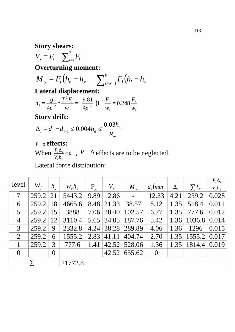
Story shears:
∑ =+=
7
1i itx FFV Overturning moment:
( ) ( )xin
xi ixntx hhFhhFM −+−= ∑ += 1 Lateral displacement:
( )i
i
i
i
i
ii w
FwF
wFTg 248.01
481.9
42
2
2
2 =
=∗=
ππδ
Story drift:
w
nniii R
hh 03.0004.01 ≤≤−=∆ −δδ
∆−P effects: When 1.0<
∆
xx
ix
hVP , ∆−P effects are to be neglected.
Lateral force distribution:
level iw xh xxhw xF xV xM ( )mmiδ i∆ ∑ xP xx
ix
hVP ∆
7 259.2 21 5443.2 9.89 12.86 - 12.33 4.21 259.2 0.028 6 259.2 18 4665.6 8.48 21.33 38.57 8.12 1.35 518.4 0.011 5 259.2 15 3888 7.06 28.40 102.57 6.77 1.35 777.6 0.012 4 259.2 12 3110.4 5.65 34.05 187.76 5.42 1.36 1036.8 0.014 3 259.2 9 2332.8 4.24 38.28 289.89 4.06 1.36 1296 0.015 2 259.2 6 1555.2 2.83 41.11 404.74 2.70 1.35 1555.2 0.017 1 259.2 3 777.6 1.41 42.52 528.06 1.36 1.35 1814.4 0.019 0 0 42.52 655.62 0
∑ 21772.8
114
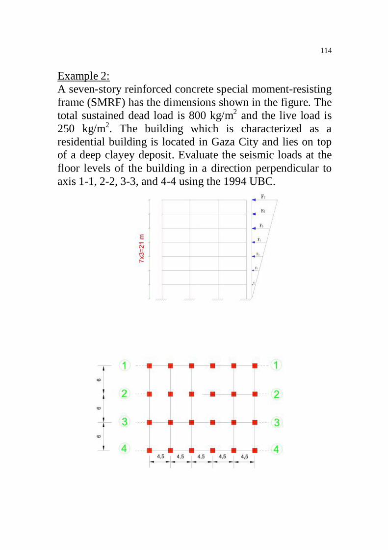
Example 2: A seven-story reinforced concrete special moment-resisting frame (SMRF) has the dimensions shown in the figure. The total sustained dead load is 800 kg/m2 and the live load is 250 kg/m2. The building which is characterized as a residential building is located in Gaza City and lies on top of a deep clayey deposit. Evaluate the seismic loads at the floor levels of the building in a direction perpendicular to axis 1-1, 2-2, 3-3, and 4-4 using the 1994 UBC.

115
Solution:
12R,0.2S ,1I ,075.0Z w ==== Since the building is residential, no live load is to be used in seismic weight calculation Weight of floor = ( )( ) tons3245.22188.0 = Total seismic weight = ( ) tons22687324 = Building natural period, T
( ) 4/3nh073.0T =
( ) sec716.021073.0T 4/3 ==
( )( )
75.2sec12.3716.0
225.1T
S25.1C 3/23/2 >=== N.O.K
075.0229.01275.2
RC
w>== O.K
The base shear V is given by
( )( )( )tons98.38
12226875.20.1075.0
RWCIZ
Vw
===
( )( ) tons95.198.38716.007.0TV07.0F sec,7.0T t ===>
V5.0< O.K Vertical Distribution of Force:
( )∑ =
−= 7
1i i
xxtx
FhwFV
F

116
Lateral force distribution: level iw xh xxhw xF xV xM
7 324 21 6804 9.26 11.21 - 6 324 18 5832 7.93 19.14 33.63 5 324 15 4860 6.61 25.75 91.05 4 324 12 3888 5.29 31.04 168.3 3 324 9 2916 3.97 35.01 261.42 2 324 6 1944 2.64 37.65 366.45 1 324 3 972 1.32 38.97 479.40 0 0 38.97 596.31
∑ 27216