4 dualsport sc suspension system for ram 1500 …
TRANSCRIPT
INS
TALL
ATIO
N G
UID
E
4” DUALSPORT sc SUSPENSION system
for RAM 1500
AEV30303AFLast Updated: 02/17/20

ii
PLEASE READ BEFORE YOU STARTTO GUARANTEE A QUALITY INSTALLATION, WE RECOMMEND READING THESE INSTRUCTIONS THOROUGHLY BEFORE BEGINNING ANY WORK. THESE INSTRUCTIONS ASSUME A CERTAIN AMOUNT OF MECHANICAL ABILITY AND ARE NOT WRITTEN NOR INTENDED FOR SOMEONE NOT FAMILIAR WITH AUTO REPAIR.
INCLUDED PARTS QTY REQUIRED TOOLS
Front Suspension Kit 1 Full metric socket and wrench setRear Suspension Kit 1 (impact wrench preferred for certain tasks)
Front Skidplate 1 Strut compressorFront Knuckles 2 Large hammerShocks 4 Metric Allen keys
Trim removal toolTorque wrenchTransmission jack (preferred)
NOTE: If using the AEV Mesa wheel along with this suspension, we suggest not putting stick on wheel weights within the inner 1” of the wheel barrel, otherwise they may interfere the tie rod ends.

1
I. Front SuspensionA. DISASSEMBLY1. Raise vehicle off ground, place frame securely on hoist or jack stands with wheels at least 6” off the ground.
2. Remove wheels and tires.
3. Remove top nut, washer, and bushings from sway bar end links. Set hardware aside, it will be reused later. Leave bottom of end links attached to lower control arms.
4. Remove brake calipers from knuckles and hang securely from frame. Remove rotors.
5. Remove ABS sensor wire connector from rear of wheel liner on both sides. Leave connected at wheel hub. Take note of wire routing for reinstall later. Unclip wire from knuckle, tuck wire and plug safely out of the way, it will be removed with knuckle.
6. Loosen jam nuts on outer tie rod ends.
7. Remove outer tie rod end from knuckle.
8. Loosen upper control arm mounting bolts on the frame to allow free movement of arms during suspen-sion install. They do not need to be removed completely.
9. Loosen nuts on upper (21mm) and lower (24mm) ball joints. Do not remove nuts completely yet.
10. Use hammer on sides of knuckle to knock it free from ball joints.
11. Remove 36mm nut holding axle shaft to hub. Impact wrench will work best to prevent hub from spinning.
12. Remove upper ball joint nut, pull joint out of knuckle, and lean top of knuckle outward. Turn knuckle and push threaded section of axle shaft inward to unseat it from wheel hub. Pull shaft inward to remove it from wheel hub splines entirely.
13. Remove lower ball joint nut and remove knuckle from vehicle. Repeat above steps for other side.
14. Remove wheel hubs from knuckles. Retain hubs and hardware for future use.
15. Leave CV shafts attached to axle. The whole thing will be removed and reinstalled as an assembly.
16. Remove lower strut nut and bolt (21mm and 24mm) and retain for future use.
17. Unbolt lower control arms from frame and remove from vehicle. Retain arms and hardware for future use.
18. Remove rearward front suspension cross-member and hardware and discard (fig. 1).
REAR
Figure 1

2
19. Mark line on front drive shaft flanges to ensure proper alignment when reinstalled. Remove 4 bolts on flange and tie drive shaft up out of the way.
20. Unplug wiring harness from front differential (passenger side).
21. Support front differential with trans jack or ratchet straps to frame and remove the 7 mounting bolts. Some trucks will require wiring harness at bottom of engine to be unclipped and moved out of the way to access bolts on driver side. If unable to move harness enough, steering rack can be removed to pro-vide better bolt access. Once all mounting bolts are removed, carefully remove differential from vehicle.
B. installation1. Mark and trim areas shown on frame cross-members:
A. Driver rear lower control arm (LCA) bracket to clear differential (fig. 2).
B. Rear-most brackets for cam bolt clearance (fig. 3).
C. Bottom of LCA brackets to clear relocated LCAs (fig. 4).
D. Inside of front LCA bracket to remove radius (fig. 5).
E. Paint raw steel edges to prevent rust.
REMOVE
FRONT
Figure 2
REMOVEFigure 3
REMOVE REMOVEREMOVE REMOVE
Figure 4
REMOVE
FRONT
Figure 5

3
2. Fit up front drop brackets to cross-member to check fitment/clearance. Radius on factory bracket must be trimmed until drop bracket sits flush.
3. Install front suspension drop brackets:
A. Install forward most LCA brackets(NRMS0521 and NRMS0522) and cam centering blocks (NRMS5002) loosely with 18mm bolt pointed forward. Install chamfered edges of cam centering blocks against frame so they fully seat into pocket. Press bracket tightly against front and bottom of cross-member, then mark hole to be drilled in front face of cross-member. Remove bracket and drill 1/2” hole (fig. 6) Apply paint to the hole for rust protection.
Figure 6
B. Reinstall front LCA drop brackets. Front face mounts with M12x55mm fully threaded bolt and flange nut. Long end of M12x55mm bolt must stick forward for skid plate to mount to later (fig. 7) Install rear portion of front brackets (NRMS0523 and NRMS0524) to frame pockets using 18mm bolts and additional cam centering blocks (NRMS5002). Bottom mounts with M12x35mm bolts, wash-ers, and flange nuts that will sandwich both brackets against frame. Bolts should point upwards. Leave loose at this time.
Figure 7 Left: Front View Right: Rear View
4
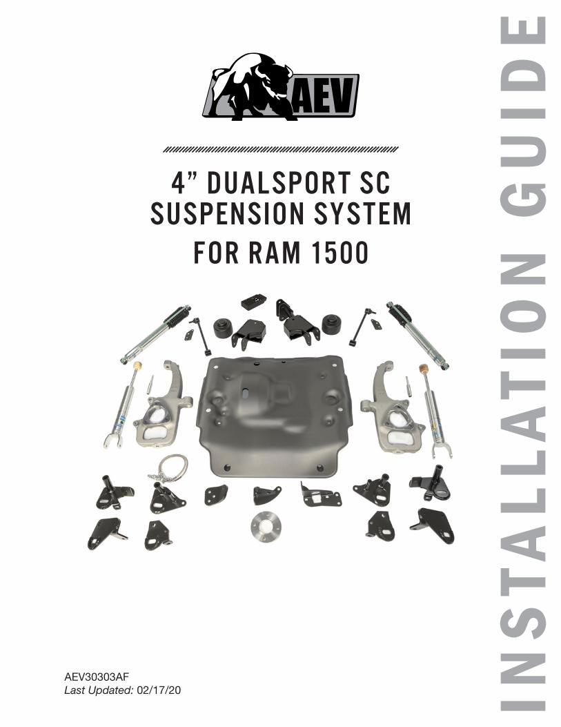
C. Install rear LCA brackets (NRMS0525, NRMS0526, NRMS0527, and NRMS0528) as shown (fig. 8). M12x150mm bolts and washers must be inserted pointing rearward in order to clear differential and retain skidplate. Leave nuts off of them until skidplate is installed. M18 bolts should also point rearward, nuts can be loosely installed.
Figure 8
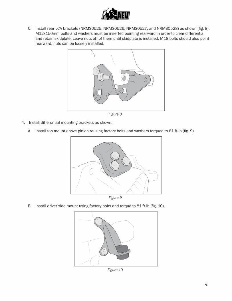
4. Install differential mounting brackets as shown:
A. Install top mount above pinion reusing factory bolts and washers torqued to 81 ft-lb (fig. 9).
Figure 9
B. Install driver side mount using factory bolts and torque to 81 ft-lb (fig. 10).
Figure 10

5
C. Install passenger bracket using M12x45mm bolts and flange nuts torqued to 75 ft-lb, then install u-bolt as shown. Thread one 3/8” nut onto u-bolt before installing it onto differential and bracket. Install u-bolt to differential and bracket, then install two 3/8” non-flange nuts to outside face, and tighten to 22 ft-lb, being sure that the rear nut is still loose. Once front nuts are tight, tighten rear nut against bracket (fig. 11).
Figure 11
D. Install bushings into front differential brackets so that steps are inside hole in brackets. Insert 40mm sleeves into bushings (fig. 10—11).
5. Raise differential back into vehicle and strap safely into place .
6. Reinstall lower control arms using factory hardware. Front cam bolts should point forward and rear bolts should point rearward for ease of alignment once everything is assembled. Tighten all 18mm drop bracket hardware to 155 ft-lb. Tighten all 12mm drop bracket hardware to 70 ft-lb. Leave LCA cam bolts loose at this time.
7. Strut replacement:
A. Using proper strut compressor, disassemble factory struts. Spring, isolator, lower spring seat, top cap, and all hardware will be reused. Lower spring seat will need to be hammered or pressed off of factory strut.
B. AEV-spec Bilstein struts have grooves for multiple ride height variations. Trucks with factory bumper should use second groove from bottom of strut (toward mounting clevis). Trucks with AEV bumper/winch combo should use third groove. Trucks with unusually heavy accessories such as snow plows may want to use top groove (away from mounting clevis) to maintain ride height.
C. Follow instructions in Bilstein shock package for reassembly of strut.

6
8. Install strut onto vehicle. Use factory flange nuts to mount onto upper frame mount and torque to 40 ft-lbs. Attach bottom end to LCA using factory hardware. Do not torque lower mount until vehicle is set at ride height.
9. Install original wheel bearings and hardware onto AEV knuckles. Torque bolts to 134 ft-lb.
10. Raise knuckles into place, first engage lower ball joint into tapered hole and loosely install retaining nut. Feed CV shaft into wheel bearing, then engage upper ball joint and install nut. Torque upper ball joint to 40 ft-lb, then an additional 200°. Torque lower to 38 ft-lb, then an additional 90°. Torque half-shaft nut to 185 ft-lb. Do not install tie rod ends to knuckles yet.
11. Snug LCA cam bolts.
12. Reinstall speed sensor connector, route wire same as original using hole in wheel liner to retain it.
13. Clamp off and remove factory soft brake lines from calipers then reinstall brake rotors and calipers.
14. Install the supplied braided stainless lines at the caliper end first. Remove the factory soft lines from the frame end and install the new stainless lines. Angle the fitting upward and inboard as shown. Route line away from tire, CV shaft, and other moving parts. Bleed brakes to remove any air from lines. Attach to speed sensor wire using wire ties. NOTE: We recommend double checking clearances once vehicle is set at ride height.

7
15. Remove factory outer tie rod ends from vehicle:
A. If using AEV low profile tie rod ends, they can be installed now. No trimming is required. Snug jam nuts into place, they do not need to be fully torqued because vehicle will need front end alignment.
B. If reusing factory outer tie rod ends, the inner tie rod ends will need to be trimmed slightly to allow correct toe in. Carefully trim 1/4” off threaded end of inner tie rod (fig. 12) Clean and deburr end of threads and reinstall factory outer tie rod ends. Snug jam nuts into place, they do not need to be fully torqued because vehicle will need front end alignment.
Figure 12
C. Install tie rod end to tapered hole in knuckles and torque bolt to 22 ft-lb, then an additional 90°.
16. Install sway bar endlink extensions onto factory endlinks and torque to 16 ft-lb. Reinstall washers, bushings, and nuts to secure sway bar to new endlink extensions. Torque nut to 16 ft-lb. (fig. 13).
Figure 13

8
17. Carefully install skidplate onto vehicle:
A. Place bushings onto rear skid cross-member, 1 on top of horizontal surface and 1 inside/under-neath. Install 40mm sleeve through bushings (fig. 14).
Figure 14
B. Install 1 washer on each M12x55mm bolt sticking forward of front suspension cross-member.
C. Raise rear of skidplate first and engage rear cross-member mounts onto M12x150mm bolts at rear LCA brackets.
D. Lift front of skidplate so M12x55mm bolts in front cross-member pass through slots in skidplate bracket. Loosely install M12 flange nuts onto both bolts to hold skidplate up (fig. 15).
Figure 15

9
E. Insert M12x25mm from bottom of skidplate into LCA brackets at all 4 locations and install flange nuts from the top (fig. 16).
Figure 16
F. Install M12x35mm bolts and washers to rear inboard skid plate mounts, pointing toward rear of vehicle (fig. 17). Install M12 flange nuts to all four rear mounting bolts.
Figure 17
G. Tighten bottom skidplate mounting bolts to 75 ft-lb.
H. Tighten front and rear skidplate mounting bolts to 75 ft-lb.

10
18. Attach differential to skidplate:
A. Remove retaining straps and carefully lower differential onto skidplate.
B. Align front bushings with skidplate holes. Feed M12x70mm bolts up from bottom. Place cupped washer on top of bushings with dish facing downward, then loosely install M12 flange nuts (fig. 18).
C. Place cupped washer on top of bushing. Raise pinion and place long tube spacer between cupped washer and upper bracket. Slide cupped washer into place below bottom of bushing, then feed M12x-220mm bolt up from bottom of skid, through the cupped washers and sleeve, through tube spacer, and up through pinion bracket. Install flange nut to top of bolt and bracket (fig. 18).
Figure 18
D. Ensure differential is aligned with all mounting holes and tighten hardware to 75 ft-lb.
E. Plug wire harness back in through hole in bracket (fig. 19).
Figure 19

11
F. Install drive shaft spacer and reattach drive shaft using alignment marks. Attach with M12x45mm bolts and torque to 75 ft-lb.
19. Install wheels and tires, set vehicle at ride height, and torque remaining hardware:
A. Upper control arm bolts (130 ft-lb).
B. Lower strut mount (125 ft-lb).
C. Lower control arm cam bolts (155 ft-lb). Vehicle will need alignment, so these will be torqued at that point as well.
II. Rear SuspensionA. Disassembly1. Raise vehicle off ground, place frame securely on hoist or jack stands with wheels at least 6” off the ground.
2. Remove wheels and tires.
3. Remove inner fender liners, retain liners and hardware.
4. Disconnect brake line bracket at frame and retain hardware.
5. Disconnect and remove sway bar links and retain hardware.
6. Support axle and remove shocks. AEV-supplied tool (fig. 20) will help for holding nut on top inside shock mounts. Retain hardware, discard shocks.
Figure 20
7. Loosen track bar bolts at both ends. Axle end can be removed completely. Hardware will be replaced.
8. Loosen all 8 control arm bolts. These are torque to yield, so all bolts will be replaced later.
9. Lower axle until springs can be removed, then remove them.

12
B. installation1. Install geometry correction brackets one side at a time, as shown. Install all hardware before torquing
to specs below.
A. Use provided M14 nut and bolt along with short sleeve spacer at factory track bar location with new bracket. Torque to 150 ft-lb. (fig. 21). To tighten bolts inside bumpstop spacers, place socket on bolt head from inside, then feed 3/8” extension through access hole in top of brackets.
Figure 21
B. Fasten brackets to axle using M12x35mm hardware as shown (fig. 22). Torque to 75 ft-lb.
Figure 22

13
C. Reuse factory upper control arm (UCA) hardware and provided sleeves at factory UCA location. Torque to 150 ft-lb.
D. Install UCA onto new bracket using new M16 hardware provided in kit, do not tighten until vehicle is sitting on the ground at ride height.
E. Install track bar onto new bracket using new M14 hardware, do not tighten until vehicle is sitting on the ground at ride height. Replace frame end hardware with new provided hardware.
2. One at a time replace all control arm mounting hardware with new hardware provided in kit. Do not tighten until vehicle is sitting on the ground at ride height.
3. Install coil spacers onto spring pad on axle. Make sure spring pad is clean of debris so spacer sits level. Lower axle until spring can be inserted between upper mount and spring spacer, then install spring. Be careful not to stress brake lines (fig. 23).
Figure 23

14
4. Install new shocks using factory hardware. Use provided tool to help hold top inside nut. Torque bolts to 100 ft-lb.
5. Loosely install brake line relocation brackets using factory hardware, and install new sway bar endlinks using M12x70mm hardware as shown (fig. 24). Do not install lower end of endlinks yet.
6. Carefully bend brake line to line up to the new mounting bracket and install using provided M8 hard-ware. Install ABS sensor into hole with existing clip (fig. 24).
Figure 24
7. Connect bottom end of sway bar end links and torque to 79 ft-lb. Axle will need to be raised slightly from position shocks were installed in.
8. Reinstall fender liners, wheels, and tires. Place vehicle on level surface at ride height.
9. Tighten all control arm bolts to 230 ft-lb. Torque both track bar bolts to 150 ft-lb.
NOTE: Vehicle will need a full front end alignment after suspension kit installation.