4-3. factory mode adjustments - turuta electronics world · 4-3. factory mode adjustments 4-3-1...
TRANSCRIPT

4-3. Factory Mode Adjustments
4-3-1 Entering Factory ModeTo enter ‘Service Mode’ Press the remote -control keys in this sequence :- If you do not have Factory remote - control
INFOPower OFF MENU MUTE Power On
4-3-2 How to Access Service ModeUsing the Customer Remote
Turn the power off and set to stand-by mode.1.
Press the remote buttons in this order; POWER OFF- INFO - MENU - MUTE to turn the set on.2.
The set turns on and enters service mode. This may take approximately 20 seconds.3.
Press the Power button to exit and store data in memory. 4. - If you fail to enter service mode, repeat steps 1 and 2 above.
Initial SERVICE MODE DISPLAY State 5.
OptionControl
SVC
Expert
ADC/WB
Advanced
T-TDT5DEUC-XXXXT-TDT5DEUS-XXXXEDID SUCCESSCALIB : AV X COMP X PC X HDMI XOption : XXXX XXXX XXXX X
T-TDTDEU-XXXSDAL-XXXRFS : P0155 T-TDT5DEUC20XX-XX-XXTYPE : XXMODEL : XXXXXMAC Not AvailableFACTORY DATA VER : XXXEERC VERSION : XXXDTP-AP-COMP-XXX-XXDTP-HIIG-XXXX-XDTP-BP-XXXXDATE OF PURCHASE : XX/XX/XX
* How to enter the hidden factory mode. a. into the factory mode b. move the tap to Advanced c. key input : 0 + 0 + 0 + 0 ** hidden menu : Advanced
6. Buttons operations withn Service Mode
Menu Full Menu Display/Move to Parent Menu
Direction Keys / Item Selection by Moving the Cursor
Direction Keys / Data Increase / Decrease for the Selected Item
Source Cycles through the active input source that are connected to the unit

4-3-3 Factory Data
Option �
OPTION Factory Name Data Range Use
Factory Reset
Type
NONE/19O6TH0C/19A6TH0C/22I6TH0C/22A6TH0C/22D6TH0C/22P6TH0C/26A6AH0C/26D6AH0C/26L6AH0C/26P6AH0C/32A6AH0C32D6AH0C/32L6AH0C32P6AH0C/32A6AF0C/32L6AF0C/32A1AF0C/32L1AF0C/37L6AF0C/37L1AF0C/40A6AF0C/40D6AF0C/40L6AF0C/40A1AF0C/40L1AF0C/40A1UF0C/40D1UF0C/40L1UF0C/46A6AF0C/46D6AF0C/46L6AF0C/46A1AF0C/46L1AF0C/46A1UF0C/46D1UF0C/46L1UF0C/55A1UF0C/55L1UF0C/65L1UF0C/19R6TH0E/22D6TH0E/26D6AH0E/32D6AH0E32D6UF0E/32A1UF0E/32D1UF0E/37L6UF0E/37D1UF0E/37L1UF0E/40D6UF0E/40A1UF0E/40D1UF0E/46D6UF0E/46L6UF0E/46A1UF0E/46D1UF0E/46L1UF0E/55A1UF0E/55D1UF0E/55L1UF0E/65L1UF0E/42HHcD3/50HHcD450FArN4/50FArV458FArN1/58F
ArV163FArN1/
Select Panel Type
12 : inch 3 : vendor 4 : refresh 5 : POL
6 : resolution 7 : multi 8 : BLU
Local Set EU EU/EU_Italy/EU_Africa/EU_Israel/NORDIG/AD_Au/CIS Select Area
Model UC5100
LC350/LC450/LC450H/LC451/LC452/LC457HLC459H/LC480/LC530/LC530H/LC539H/LC540/LC550/LC560/LC580/LC570/
LC610/LC620/LC630/LC631/LC632/LC633/LC640/LC650/LC652/LC653/LC654/LC670/
UC400/UC400H/UC4010/UC5000/UC5100/UC6000/UC6200/UC6300/UC6400/UC6400H/UC6500/UC6510/UC6530/
UC6540/UC6550/UC6600/UC6620/UC6630/UC6700/UC6720/UC6730/UC6740/UC6800/UC6830/UC6900/UC6900H/
UC8000/ PC420/PC430/PC431/PC432/PC450/PC451/PC480/PC520/PC530/PC531/PC540/PC541/PC550/PC551/PC560/PC580/PC590/PC670/PC6100/PC6400/PC6500/PC7000/PC7700/
PC8000
Select Model
TUNER DRXKSEMCO DRXKSEMCO/S2Semco/T2CXD/DRXKSEM_E/DRXKALPS/DRXKSEN_2/DRXKXG
EU : DRXKSEMCO
AU : DRXKALPS
satellite : S2Semco
DDR SAMSUNG / Etron SAMSUNG SAMSUNG
Front Color NONE/W-MILKY/T-M-Brn/T-W-Brn/T-W-Gray/W-D-Gray/W-M-Whit/W-Violet/T-C-Gray/T-R-BLK/S-BLK/S-RBLK/S-C-Gray/
Select Design for Illuminance
Sensor

Control �
Control Factory Name Data Range
EDID
Sub Option
Shop Option
Sound
EDID Factory Name Data Use
EDID ON/OFF OFF
Download EDID data to EEPROM. 1. Set "ON" of EDID ON/OFF. 2. Go EDID WRITE ALL and Push Enter or ► button. 3. If You See Success message, SET "OFF" of EDID ON/OFF.
EDID WRITE ALL …
EDID WRITE PC …
EDID WRITE HDMI …
EDID WRITE HDMI1 …
EDID WRITE HDMI2 …
EDID WRITE HDMI3 …
EDID WRITE HDMI4 …
EDID 1.2 PORT …
EDID WRITE DVI …
Sub Option Factory Name Data RANGE Use
RS-232 Jack UART Debug/Logic/UART Select Setting of UART port. Initial value is "UART"
Watchdog ON ON/OFF Select Watchdog. Initial value is "ON"
WD Count 0 255 Watchdog Count. Read Only.
Dimm Type EXT fixed Select Dimming Type. Initial value is "EXT"
Lvds Format JEIDA JEIDA/VESA/19INCHSelect LVDS format. 19inch : VESA" other inch : "JEIDA"
OTN Server Type operating operating/development
OTN Test Server OFF OFF/ A/B/C/D/E Zone
OTN Support ON ON/OFF
OTN Reset not modifyed
OTN Duration OFF ON/OFF
OTN Fail Test OFF ON/OFF
T-CON USB Download Failure fixed
View Log not modifyed
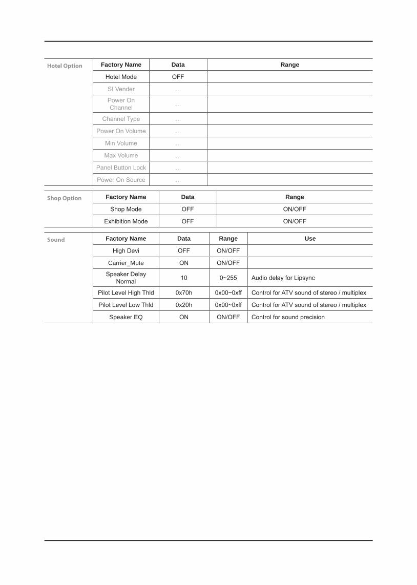
Hotel Option Factory Name Data Range
Hotel Mode OFF
SI Vender …
Power On Channel …
Channel Type …
Power On Volume …
Min Volume …
Max Volume …
Panel Button Lock …
Power On Source …
Shop Option Factory Name Data Range
Shop Mode OFF ON/OFF
Exhibition Mode OFF ON/OFF
Sound Factory Name Data Range Use
High Devi OFF ON/OFF
Carrier_Mute ON ON/OFF
Speaker Delay Normal 10 0~255 Audio delay for Lipsync
Pilot Level High Thld 0x70h 0x00~0xff Control for ATV sound of stereo / multiplex
Pilot Level Low Thld 0x20h 0x00~0xff Control for ATV sound of stereo / multiplex
Speaker EQ ON ON/OFF Control for sound precision

SVC �
SVC Factory Name Data Range
Test Pattern
fixed
Panel Auto Setting
Panel Display Time 0Hr
Logic Usb D/L off
Tuner Status
Test Pattern Factory Name Data Range Use
Pattern Sel OFF OFF/ White/Grey/Black Red/Green/Blue
Test for Input of Scaler. If you can see pattern well, there is problem at input of Scaler.
FRC PC Mode … ON/OFF
Logic Pattern Sel … Not modified
Logic Level Sel … Not modified
TUNER STATUS Factory Name Factory Name Range
DVB
SNR Not modified
BER Not modified
Singal Strength Not modified
Bandwidth Not modified
Frequency Not modified
LNA Status Not modified
FFT Not modified
Modulation Not modified
Code Rate Not modified
GI Not modified
Hier Modulation Not modified
Frequency Offset Not modified
Timing Offset Not modified
AGC Not modified
UCB Not modified
PLL Type Not modified
DEMOD Type Not modified
TPS LOCK Not modified
RS Lock Not modified
SSI Not modified
SQI Not modified

ISDB-T FFT Size_1 Not modified
Guard Interval_1 Not modified
Freq. Offset_1 Not modified
SNR_1 Not modified
IF AGC_1 Not modified
TMCC Lock_1 Not modified
TS Packet_1 Not modified
Master Lock_1 Not modified
A_Modulation_1 Not modified
A_Code Rate_1 Not modified
A_Timer InterLeave_1 Not modified
A_Segments Num_1 Not modified
A_Ber_1 Not modified
B_Modulation_! Not modified
B_Code Rate_1 Not modified
B_Timer InterLeave_1 Not modified
B_Segments Num_1 Not modified
B_BER_1 Not modified
C_Modulation_1 Not modified
C_Code Rate_1 Not modified
C_Timer InterLeave_1 Not modified
C_Segments Num_1 Not modified
C_BER_1 Not modified
Expert �
SVC Factory Name Data Range
N / D ADJ Off Off / On / FIX
SOURCE ... Not modified

ADC/WB �
ADC/WB Factory Name Data Range
ADC
ADC Target
ADC RESULT
WB
ADC Factory Name Data Range
AV Calibration Success Success / Failure
Comp Calibration Success Success / Failure
PC Calibration Success Success / Failure
HDMI Calibration Success Success / Failure
ADC Target Factory Name Data Range
1st_AV_Low 64 0 ~ 1023
1st_AV_High 880 0 ~ 1023
1st_AV_Delta 2 0 ~ 7
1st_COMP_Y_Low 64 0 ~ 1023
1st_COMP_Y_High 940 0 ~ 1023
1st_COMP_Delta 2 0 ~ 7
1st_PC_R_Low 16 0 ~ 1023
1st_PC_R_High 1004 0 ~ 1023
1st_PC_Delta 2 0 ~ 7
2nd_AV_R_Low 4 -
2nd_AV_G_Low 4 0 ~ 1023
2nd_AV_B_Low 4 -
2nd_AV_R_High 940 -
2nd_AV_G_High 940 0 ~ 1023
2nd_AV_B_High 940 -
2nd_AV_Delta 2 0 ~ 7
2nd_COMP_R_Low 4 -
2nd_COMP_G_Low 4 0 ~ 1023
2nd_COMP_B_Low 4 -
2nd_COMP_R_High 940 -
2nd_COMP_G_High 940 0 ~ 1023
2nd_COMP_B_High 940 -
2nd_COMP_Delta 2 0 ~ 7
2nd_PC_R_Low 4 -
2nd_PC_G_Low 4 0 ~ 1023
2nd_PC_B_Low 4 -

2nd_PC_R_High 940 -
2nd_PC_G_High 940 0 ~ 1023
2nd_PC_B_High 940 -
2nd_PC_Delta 2 0 ~ 7
2nd_HDMI_R_Low 4 -
2nd_HDMI_G_Low 4 0 ~ 1023
2nd_HDMI_B_Low 4 -
2nd_HDMI_R_High 940 -
2nd_HDMI_G_High 940 0 ~ 1023
2nd_HDMI_B_High 940 -
2nd_HDMI_Delta 2 0 ~ 7
ADC RESULT Factory Name Data Range
1st_Y_GH 0 0 ~ 255
1st_Y_GL 0 0 ~ 255
1st_Cb_BH 0 0 ~ 255
1st_Cb_BL 0 0 ~ 255
1st_Cr_RH 0 0 ~ 255
1st_Cr_RL 0 0 ~ 255
2nd_R_L 132 0 ~ 255
2nd_G_L 132 0 ~ 255
2nd_B_L 132 0 ~ 255
2nd_R_H 50 0 ~ 255
2nd_G_H 50 0 ~ 255
2nd_B_H 50 0 ~ 255
WB Factory Name Data Range
Sub Brightness 128 0 ~ 255
R_Offset 512 0 ~ 1023
G_Offset 512 0 ~ 1023
B_Offset 512 0 ~ 1023
Sub Contrast 128 0 ~ 255
R_Gain 512 0 ~ 1023
G_Gain 512 0 ~ 1023
B_Gain 512 0 ~ 1023
Movie R Offset - 0 ~ 1023
Movie B Offset - 0 ~ 1023
Movie R Gain - 0 ~ 1023
Movie B Gain - 0 ~ 1023
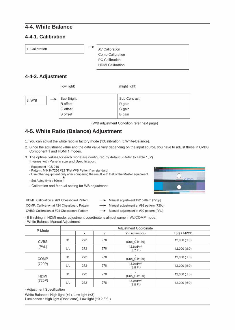
4-4. White Balance
4-4-1. Calibration
1. Calibration
AV CalibrationComp CalibrationPC CalibrationHDMI Calibration
4-4-2. Adjustment
3. W/B
(low light) (hight light)
Sub BrightR offsetG offsetB offset
Sub ContrastR gainG gainB gain
(W/B adjustment Condition refer next page)
4-5. White Ratio (Balance) Adjustment
You can adjust the white ratio in factory mode (1:Calibration, 3:White-Balance).1.
Since the adjustment value and the data value vary depending on the input source, you have to adjust these in CVBS, 2. Component 1 and HDMI 1 modes.
The optimal values for each mode are configured by default. (Refer to Table 1, 2) 3. It varies with Panel’s size and Specification.- Equipment : CS-210 - Pattern: MIK K-7256 #92 "Flat W/B Pattern" as standard - Use other equipment only after comparing the result with that of the Master equipment.
- Set Aging time : 60min
- Calibration and Manual setting for WB adjustment.
HDMI : Calibration at #24 Chessboard Pattern Manual adjustment #92 pattern (720p)
COMP: Calibration at #24 Chessboard Pattern Manual adjustment at #92 pattern (720p)
CVBS: Calibration at #24 Chessboard Pattern Manual adjustment at #92 pattern (PAL)
- If finishing in HDMI mode, adjustment coordinate is almost same in AV/COMP mode. - White Balance Manual Adjustment
P-ModeAdjustment Coordinate
x y Y (Luminance) T(K) + MPCD
CVBS(PAL)
H/L 272 278 -(Sub_CT:130) 12,000 (±0)
L/L 272 278 12.6cd/m2
(3.7 Ft) 12,000 (±0)
COMP(720P)
H/L 272 278 -(Sub_CT:130) 12,000 (±0)
L/L 272 278 13.0cd/m2
(3.8 Ft) 12,000 (±0)
HDMI(720P)
H/L 272 278 -(Sub_CT:130) 12,000 (±0)
L/L 272 278 13.0cd/m2
(3.8 Ft) 12,000 (±0)
- Adjustment SpecificationWhite Balance : High light (±1), Low light (±3) Luminance : High light (Don’t care), Low light (±0.2 Ft/L)

4-6. Servicing Information
4-6-1 USB Download MethodSamsung may offer upgrades for TV’s firmware in the future. Please contact the Samsung call center at 1-800-SAMSUNG (726-7864) to receive information about downloading upgrades and using a USB drive. Upgrades will be possible by connecting a USB drive to the USB port located on your TV.
Insert a USB drive containing the firmware (T-TDT5DEUC) 1. upgrade into the USB port on the rear of the TV.
Press the 2. MENU button to display the menu. Press the or button to select "Support", then press the ENTER button.
Press the 3. or button to select "SW Upgrade", then press the ENTER button. The message "Scanning for USB. It may take up to 30 seconds." is displayed.
The message "Upgrade version XXXX to version XXXX? 4. The system will be reset after upgrade." is displayed. Press the or to select the "OK", then press the ENTER button.
Please be careful to not disconnect the power or remove the USB drive while upgrades are being applied. The TV will turn off and turn on automatically after completing the firmware upgrade. Please check the firmware version after the upgrades are complete. When software is upgraded, video and audio settings you have made will return to their default (factory) settings. We recommend you write down your settings so that you can easily reset them after the upgrade.

4-7. How To Upgrade Sub Micom With Ddc Manager
4-7-1. TV Sub S/WOrder Description
1 Connect DDC MANAGER to the TV Set with D-SUB cable. And Power on. (USB type : MTI-2510 / parallel type : MTI-2059)
2 Enter the factory mode.Control - EDID - EDID ON/OFF Select ON.
3 Open the DDC tool. (Parallel type & USB type)
Check the setting.
4 Load the sub micom program file (T-TDT5DEUS-XXXX.BIN).
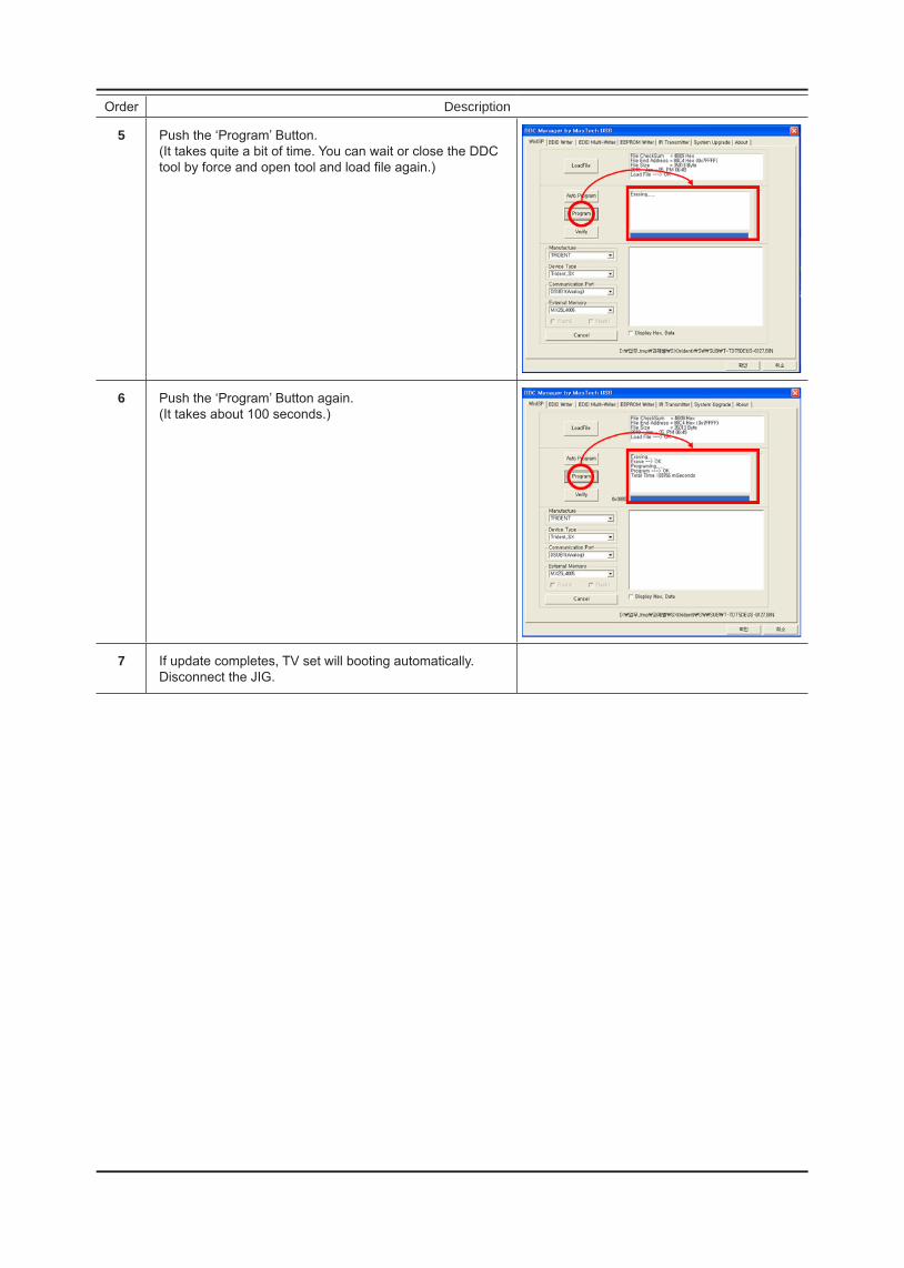
Order Description
5 Push the ‘Program’ Button. (It takes quite a bit of time. You can wait or close the DDC tool by force and open tool and load file again.)
6 Push the ‘Program’ Button again. (It takes about 100 seconds.)
7 If update completes, TV set will booting automatically. Disconnect the JIG.