3p-3w upqc with zig-zag transformer for 3p-4w distribution ... · pdf file3p-3w upqc with...
TRANSCRIPT
International Journal on Electrical Engineering and Informatics ‐ Volume 4, Number 2, July 2012
3P-3W UPQC with zig-zag transformer for 3P-4W Distribution System
Yash Pal1, A. Swarup1 and Bhim Singh2
1Department of Electrical Engineering, National Institute of Technology, Kuruksetra, Haryana, India. 2Department of Electrical Engineering, Indian Institute of Technology, New Delhi, India.
Abstract: In this paper, a new topology is developed for a three-phase four-wire (3P4W) distribution system utilizing a zig-zag transformer along with three-phase three-wire (3P3W) Unified Power Quality Conditioner (UPQC).In this proposed topology the neutral point of the star connected transformer, used for the connection of series active power filter (APF) of 3P3W UPQC, is utilized as a fourth wire for 3P4W distribution system. The zig-zag transformer is connected near the load to compensate the neutral current that may flow toward the neutral point of the series transformer of series APF. The series and shunt APF of 3P-3W UPQC are realized by readily available three-leg voltage source inverters (VSIs). For the mitigation of different power quality problems a control technique based on synchronous reference frame (SRF) theory is used for the control of UPQC. In this control scheme of UPQC, the current/voltage control is applied over the fundamental supply currents/voltages instead of fast changing APFs currents/voltages, there by reducing the computational delay and the required sensors. The performance of the proposed topology of UPQC is analyzed through simulations results using MATLAB software with its Simulink and Power System Block set toolboxes. Key Words: Active powers filter (APF), Power-factor correction, Load balancing, UPQC, Voltage and current harmonics, Neutral current compensation, Star-delta transformer.
1. Introduction In the deregulated power market, the main objective of the electric utility companies is to deliver quality power to their consumers. But this is becoming increasingly difficult because poor-power factor loads and modern power electronic devices have been widely used in power system applications. Different devices such as rectifiers, inverters, adjustable speed drives, computer power supplies, furnaces and traction drives lead to non-linear current waveforms. These nonlinear loads degrade electric power quality, the quality degradation leads to low power-factor, low efficiency, overheating of transformers and so on [1]. In addition to this, on a 3P4W distribution system the load is hardly found balanced and hence there is an excessive neutral currents of fundamental as well as harmonic frequencies [2-3]. To regulate the power quality different agencies have recommended different standards such as such as the IEEE-519 standard, IEEE Std.141-1993, IEEE Std. 141, 1993,etc [4-5]. To improve the reliability and power quality on a distribution, a group of devices, called Custom Power Devices (CPD) [6] are in use now days. The compensating type CPD mainly covers three devices namely D-Statcom [7], DVR [8] and UPQC [9-16]. The D-Statcom is a shunt connected device and generally mitigates the current based distortions. The DVR is a series connected devices, which is responsible for the mitigation of voltage based distortion. Since the UPQC is a combination of shunt and series APF, hence it mitigates the current and voltage based distortions, simultaneously. Generally, 3P4W distribution system is realized by providing a neutral conductor along with three power conductors from the utility transformer substation as shown in Figure1. If neutral conductor is not available then neutral wire may be realized utilizing a three-phase Δ-Y transformer at the distribution level as shown in igure 2. In the event of non-availability of
Received: January 7th, 2011. Accepted: March 21th, 2012
231

neutral, than a new topology/structure has been reported for 3P-4W system in UPQC based applications [11]. In this reported topology neutral of the series transformer, used for the connection of series APF, is considered as the fourth wire for the 3P-4W system. In this topology the neutral current that may flow towards transformer neutral is compensated by using a four-leg VSI for shunt APF of 3P3W UPQC.
N C
B
AUtility 3P4W
Three-phase
balance/unbalanced
loads/single phase loads
Figure 1. 3P-4W distribution system neutral provided from utility transformer substation
N C
B
A
C
B
A
Distribution Δ-Y transformer
To other 3P-3W Loads
Utility (3P3W)
To other 3P-4W Loads
Figure 2. 3P-4W distribution system: neutral provided from Δ-Y transformer
This paper proposes a new topology/structure for 3P4W distribution system in which the neutral of the series transformer, used for the insertion of series APF with utility, is considered as the fourth wire for the 3P-4W system and the zig-zag transformer is used for the mitigation of the neutral current that may flow towards transformer neutral. The zig-zag transformer provides a path for the neutral current and split it in among the three phases such that, the neutral current that may flow toward the transformer neutral point is effectively compensated and the transformer neutral point is always at virtual zero potential. In literature the UPQC installed for 3P4W applications mostly consider 3P4W supply [9-10], [12-16] and compensate the neutral through active compensation. For the mitigation of source neutral current, the uses of passive elements are advantageous over the active compensation due to ruggedness and less complexity. In addition to this, in a UPQC based applications, by connecting a zig-zag transformer on the load side, the realization of 3P4W distribution system is possible without disturbing the existing topology/structure of 3P3W UPQC. Moreover, the rating of the UPQC is reduced due to elimination of a fourth leg compared to three-phase four-leg VSI based UPQC. Apart from realization of 3P4W system the performance of the proposed structure/topology is evaluated for power-factor correction, load balancing, current harmonic mitigation and voltage harmonic mitigation. 2. State of the art The different topologies reported in literature of three-phase four-wire UPQC [9-16] use active compensation for the mitigation of source neutral current along with other PQ problems.
Yash Pal, et al.
232

For the mitigation of source neutral current, the uses of passive elements are advantageous over the active compensation due to ruggedness and less complexity. There are many techniques proposed for the compensation of neutral current using zig-zag transformer [17-20] in the three-phase four-wire distribution system. The application of zig-zag transformer has been reported for neutral current mitigation [17-18]. A single-phase VSI and a zig-zag transformer is also efficient for neutral current compensation [19-20].Another topology having single-phase VSI with self supporting DC bus along with zig-zag transformer is also reported for neutral current compensation[18]. For the mitigation of source neutral current along with other PQ problems, the integration of readily available three-leg VSI with zig-zag transformer has been reported in literature for three-phase four-wire D-Statcom[7]. Unfortunately, the performance of these transformers for neutral current mitigation is affected to an extent under distorted or unbalanced source voltages, which is very common in practice. The UPQC is one of the key CPDs, which takes care of both voltage and current based distortions simultaneously. Hence, the integration of zig-zag transformer with UPQC for neutral current mitigation is more justified. Moreover, in this particular work, where realization of 3P4W system is achieved in UPQC based applications, the rating of the UPQC has been reduced with the integration of a zig-zag transformer compared to four-leg based UPQC topology. 3. System Configuration and Design Figure 3 shows the 3P-3W UPQC topology, in which the neutral of the series transformer used for the connection of series APF, is considered as the fourth wire for the 3P-4W system and the zig-zag transformer is used for the mitigation of the neutral current that may flow towards transformer neutral. The UPQC is feeding a combination of linear and non-linear unbalanced load. The series and shunt APFs are realized using two readily available three-leg VSIs. The dc link of both APF is connected to a common dc link capacitor. The series APF is
ilb
ifb
ifa
isn iln
ilc
ila
Back to Back VSI
vfc
3-phase distorted supply
ifc
Zig-zag Transformer
Rsc,Lsc
Rsb,Lsb vfb
vfa Rsa,Lsa
Linear
and Non –Linear
Load
Figure 3. Detailed Configuration of 3P-4WUPQC
connected between the supply and load terminals using three single phase transformers with turn’s ratio of 5:1.The primary winding of these transformer are star connected and the secondary windings are connected in series with the three-phase supply. In addition to provide neutral wire and injecting the required voltages, these transformers are used to filter the switching ripple content in the series APF. A small capacity rated R-C filter is connected in parallel with the secondary of each series transformer to eliminate the high switching ripple content in the series APF injected voltage. The voltage source inverters for both the APFs are
3P-3W UPQC with zig-zag transformer for 3P-4W Distribution System
233

implemented with Insulated gate Bipolar Transistors ( IGBTs). In Figure1 (isa, isb , isc) ,(ila, ilb , ilc) and (ifa, ifb , ifc,),represent the source currents, load currents and shunt APF currents in phase a, b and c respectively. The source neutral current, load neutral current and neutral current of the additional connected transformers are represented by isn, iln and iTn, respectively. The injected voltages by the series APF in phase a, b and c is represented by vinja, vinjb and vinjc, respectively. For the compensation of neutral current that may flow toward the transformer neutral point because of unbalanced load, an additional zig-zag transformer is connected near the load. The zig-zag transformer provides a path for the neutral current and split it in among the three- phases such that, the neutral current that may flow towards the transformer neutral is compensated effectively. The selection criteria of interfacing inductor, dc capacitor, ripple filter and zig-zag transformer is given in the following section. A. DC Capacitor Voltage The value of the common link DC bus voltage of back to back connected VSIs of the UPQC depends on the instantaneous energy available to the UPQC [21]. For a VSI the DC link voltage is defined as
mV
V LLdc 3
22= (1)
where m is the modulation index and VLL is the ac line out voltage of UPQC. Considering modulation index as 1 and for line to line voltage (VLL =415 V), the Vdc obtained is 677.69 V and is selected as 700 V. B. DC Bus Capacitor The value of dc capacitor (Cdc) of back to back connected VSIs of the UPQC depends on the change of DC voltage during increase and decrease of the load. Using the principle of energy conservation, the equation [21] for Cdc is as follows
( ) ( )[ ] ( )tIVVVC dcdcdc α3
21 2
12 =− (2)
where Vdc is the reference dc voltage and Vdc1 is the minimum voltage level of dc bus, α is the overloading factor, V is the phase voltage, I is the phase current, and t is the time by which the dc bus voltage is to be recovered. Considering the minimum voltage level of dc the bus, Vdc1=690 V, Vdc=700 V, V=415/sqrt (3) =239.60 V, I=25.40 A, t=350µs, α=1.2, the calculated value of Cdc is 2340µF.Hence Cdc is selected as 3000 µF. C. AC Inductor The selection of the ac inductance (Lf) of VSI depends on the current ripple icr,p-p, switching frequency fs, dc bus voltage (Vdc), and Lf is given as [21]
)(123
ppcrs
dcf if
mVL
−
=α
(3)
where m is the modulation index and α is the overload factor. Considering, icr,p-p=2.5%, fs=10 KHz, m=1,Vdc=700 V, α=1.2, the Lf value is calculated to be 4.88 mH. A round-off value of Lf of 5 mH is selected in this work.
Yash Pal, et al.
234

D. Ripple Filter A low-pass first-order filter at half the switching frequency is used to filter the high-witching frequency noise from the injected voltage of series APF. Considering a low impedance of 8.1Ω for the harmonic voltage at half the switching frequency 10 KHz /2=5 KHz, the ripple filter capacitor is designed as Cf =5µF. A series resistance (Rf) of 7 Ω is included in series with the capacitor (Cf).The impedance is found to be 638Ω at fundamental frequency, which is sufficiently large, and, hence, the ripple filter draws negligible fundamental current. E. Design of zig-zag Transformer[7] The connection diagram of zig-zag transformer is shown in Figure 4(a) and the phasor diagram is shown in Figure 4(b).The zig-zag transformer acts as an open circuit for positive sequence and negative sequence component of the load current. It provides a low impedance path for the zero sequence currents and hence the supply neutral current is reduced to zero. When a zig-zag transformer is used alone as a neutral current compensator, the rating of the zig-zag transformer depends on the amount of imbalance and the harmonic content. From the phasor diagram shown in Figure 4(b) the Vza can be written in terms of per phase voltages Va and Vc as per eqn (5)
caza VKVKV 21 −= (5) where K1 and K2 are the fraction of winding in the phases. Considering phase ‘a’ as reference, and putting the values of Va, Vc and Vza in above equation, we gets
°−∠−°∠=°∠ 1200303 21 VKVVKV (6) The solution of above equation is K1=K2=1.
For a line to line voltage of 415 V, VV za 60.2393
415==
Hence, VVVV cba 33.138360.239
====
So, three single-phase transformers with turns ratio 1:1of rating 5KVA, 150 V/150 V are selected.
N
C
B
A
a1
c2
b1
b2 c1 b2
vza
a2
b1 c1
b2
c2
a1
Figure 4. (a) Zigzag transformer (b)Phasor diagram
3. Control Scheme of Series APF The control strategy for series APF is shown in Figure5. Three-phase distorted supply voltages are sensed and given to PLL which generates two quadrature unit vectors (sinwt,coswt). The sensed supply voltage is multiplied with a suitable value of gain before being given as an input to PLL. A distortion free, balanced and a constant magnitude three-phase voltage has ‘d’ component only, while ‘q’ and ‘0’ component will be zero. Hence, with
3P-3W UPQC with zig-zag transformer for 3P-4W Distribution System
235

the help of unit vectors (sinwt,coswt) obtained from PLL, an inverse Parks transformation is done for the desired peak value of the PCC voltage(ie.325V) using eqn.(7) as:
⎥⎥⎥
⎦
⎤
⎢⎢⎢
⎣
⎡
⎥⎥⎥⎥⎥⎥⎥
⎦
⎤
⎢⎢⎢⎢⎢⎢⎢
⎣
⎡
⎟⎠⎞
⎜⎝⎛ Π
+−⎟⎠⎞
⎜⎝⎛ Π
+
⎟⎠⎞
⎜⎝⎛ Π
−−⎟⎠⎞
⎜⎝⎛ Π
−
−
=⎥⎥⎥
⎦
⎤
⎢⎢⎢
⎣
⎡
00
13
2sin3
2cos
13
2sin3
2cos
1sincos
32
*
*
*d
lc
lb
la v
vvv
θθ
θθ
θθ (7)
vla vlb vlc
v*lc
v*lb
v*la Desired Load voltage
0
0
Inverse Park’s transformation
d-q-0 a-b-c
Sin wt Cos wt from 3-phase PLL
Hystresis voltage
Controller
Gate Pulses to Three leg VSI
Figure 5. Control Scheme of Series APF using SRF Theory
The computed load reference load voltages(v*
la , v*lb and v*
lc) are given to the hysteresis controller along with the sensed three phase actual load voltages (vla , vlb and vlc).The output of the hysteresis controller is switching signals to the six switches of the VSI of series APF. The hysteresis controller generates the switching signals such that the voltage at PCC becomes the desired sinusoidal reference voltage. In each control schemes of the series APF, the voltage control is applied over the fundamental voltages instead of fast changing APFs voltages, thereby reducing the computational delay. Control scheme of shunt APF The control scheme to ger the reference source (i*
sa, i*sb and i*
sc) using SRF theory is depicted in Figure6. With the help of unit vectors (sinwt,coswt) the load currents are transformed in to d-q-0 components using Park’s transformation as per the eqn.(8) :
⎥⎥⎥
⎦
⎤
⎢⎢⎢
⎣
⎡
⎥⎥⎥⎥⎥⎥⎥
⎦
⎤
⎢⎢⎢⎢⎢⎢⎢
⎣
⎡
⎟⎠⎞
⎜⎝⎛ Π
+−⎟⎠⎞
⎜⎝⎛ Π
−−−
⎟⎠⎞
⎜⎝⎛ Π
+⎟⎠⎞
⎜⎝⎛ Π
−
=⎥⎥⎥
⎦
⎤
⎢⎢⎢
⎣
⎡
lc
lb
la
q
d
iii
iii
21
21
21
32sin
32sinsin
32cos
32coscos
32
0
θθθ
θθθ (8)
Yash Pal, et al.
236

Gate
pulses
to
three
les
VSI
isa isb isc isn
i*sc
i*sb
i*sa
LPF +
O
O
Sin wt Cos wt From 3-phase PLL
Inverse Park’s transformation Park’s transformation
+
_ +
ila
ilb
ilc
Vdc
V*dc
a-b-c d-q-0
DC voltage Controller
d-q-0 a-b-c
Sin wt Cos wt From 3-phase PLL
Hystresis current
controller
Figure 6. Control Scheme of Shunt APF using SRF Theory
After calculating the d-q-0 component of the load currents, the‘d’ component is passed through a low pass filter to extract dc component of iLd. A SRF controller extracts dc quantities by a low pass filter and hence non-dc quantities (harmonics) are separated from the reference signal. The d-axis current consist of fundamental and harmonic component as
dacddcLd iii += (9) The control strategy of the shunt APF considers that the source must deliver the dc component of the direct-axis component of the load current (id dc) along with the active power current component for maintaining the dc bus and meeting the losses (iloss) in shunt APF. The output of PI (proportional-integral) controller at the dc bus voltage of the common dc link voltage of UPQC is considered as the current (iloss) for meeting its losses.
)()1()(
*)1(
*)( ndeidndendepdnlossnloss VKVVKII +−+= −− (10)
where )()( ndcadcrnde VVV −= denotes the error in Vdc calculated over reference value of Vdc. and average value of Vdc.Kpd and Kid are proportional and integral gains of the dc bus voltage PI controller. The reference direct axis source current is therefore as,
lossddcd iii +=* (11)
Three-phase reference source currents are obtained by reverse Park’s transformation using eqn. (12) with the i*
d as in (11) and i*q and i*
0 as zero.
⎥⎥⎥
⎦
⎤
⎢⎢⎢
⎣
⎡
⎥⎥⎥⎥⎥⎥⎥
⎦
⎤
⎢⎢⎢⎢⎢⎢⎢
⎣
⎡
⎟⎠⎞
⎜⎝⎛ Π
+−⎟⎠⎞
⎜⎝⎛ Π
+
⎟⎠⎞
⎜⎝⎛ Π
−−⎟⎠⎞
⎜⎝⎛ Π
−
−
=⎥⎥⎥
⎦
⎤
⎢⎢⎢
⎣
⎡
*0
*
*
*
*
*
13
2sin3
2cos
13
2sin3
2cos
1sincos
32
iii
iii
q
d
sc
sb
sa
θθ
θθ
θθ (12)
3P-3W UPQC with zig-zag transformer for 3P-4W Distribution System
237
The sensed(isa, isb and isc) and reference source currents(i*
sa, i*sb and i*
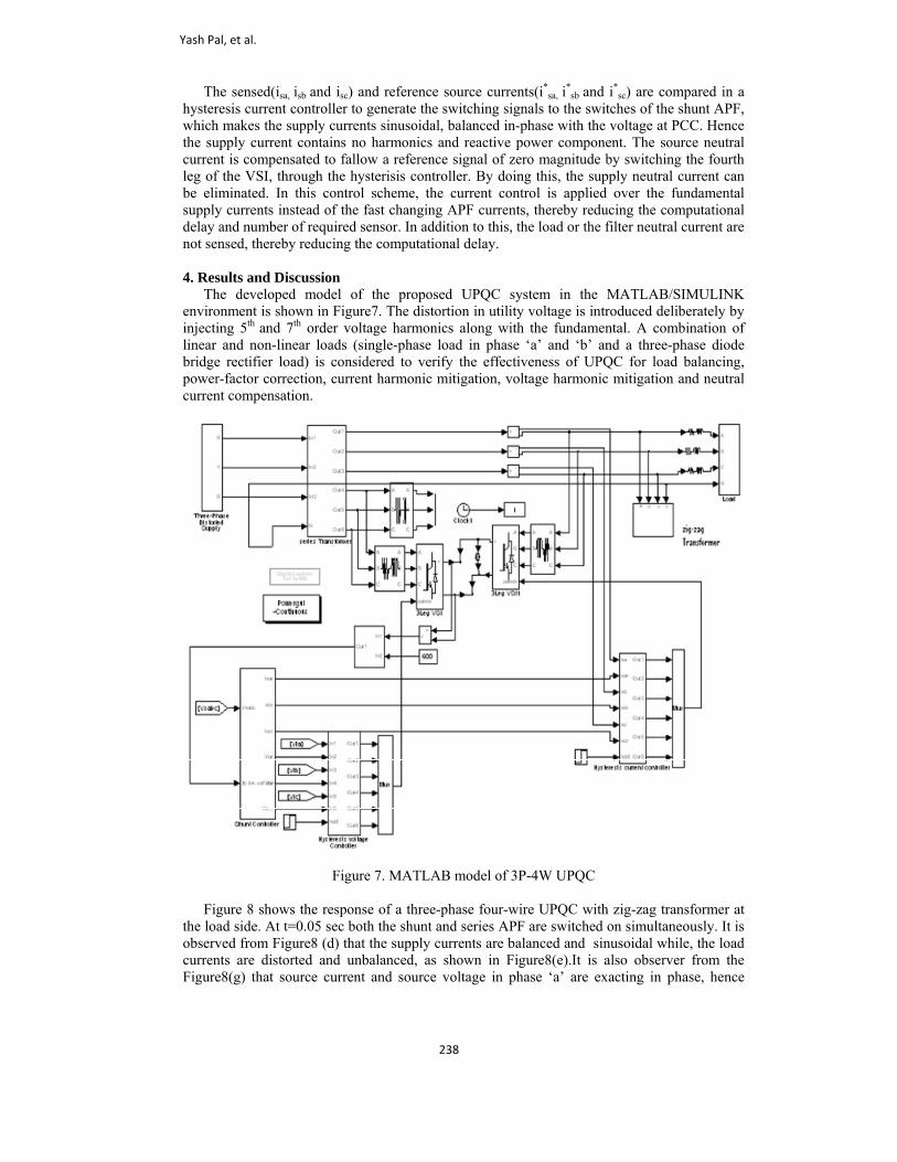
sc) are compared in a hysteresis current controller to generate the switching signals to the switches of the shunt APF, which makes the supply currents sinusoidal, balanced in-phase with the voltage at PCC. Hence the supply current contains no harmonics and reactive power component. The source neutral current is compensated to fallow a reference signal of zero magnitude by switching the fourth leg of the VSI, through the hysterisis controller. By doing this, the supply neutral current can be eliminated. In this control scheme, the current control is applied over the fundamental supply currents instead of the fast changing APF currents, thereby reducing the computational delay and number of required sensor. In addition to this, the load or the filter neutral current are not sensed, thereby reducing the computational delay. 4. Results and Discussion The developed model of the proposed UPQC system in the MATLAB/SIMULINK environment is shown in Figure7. The distortion in utility voltage is introduced deliberately by injecting 5th and 7th order voltage harmonics along with the fundamental. A combination of linear and non-linear loads (single-phase load in phase ‘a’ and ‘b’ and a three-phase diode bridge rectifier load) is considered to verify the effectiveness of UPQC for load balancing, power-factor correction, current harmonic mitigation, voltage harmonic mitigation and neutral current compensation.
Figure 7. MATLAB model of 3P-4W UPQC Figure 8 shows the response of a three-phase four-wire UPQC with zig-zag transformer at the load side. At t=0.05 sec both the shunt and series APF are switched on simultaneously. It is observed from Figure8 (d) that the supply currents are balanced and sinusoidal while, the load currents are distorted and unbalanced, as shown in Figure8(e).It is also observer from the Figure8(g) that source current and source voltage in phase ‘a’ are exacting in phase, hence
Yash Pal, et al.
238

shunt APF is compensating for the reactive power along with load balancing and current harmonic mitigation.Figure8(i) shows that there is a neutral load current because of the unbalanced load , but the star-delta transformer is able to mitigate the neutral current that may flow towards the neutral of the series transformer as shown in Figure8(h). Figure 8(i) shows the neutral current of the zig-zag transformer, which is exactly opposite to the load neutral current.
Figure 8. Dynamic response of 3P-4W UPQC under distorted supply voltage and varying load
conditions In addition to this, the series APF starts compensating voltage harmonics immediately by injecting out of phase harmonic voltage, making load voltage at load distortion free. The voltage injected by series APF is shown in Figure 8 (c). Figure 8(k) shows that during the operation of UPQC dc voltage across the capacitor of back to back VSI is maintained to its reference value. In phase ‘c’ the THD of the source current is 2.73%, while the load current THD is14.4% as shown in Figure9 and Figure10, respectively. The harmonic spectrum of load voltage before compensation is shown in Figure11, while the harmonic spectrum of load voltage after compensation is shown in Figure12. The load voltage THD is improved form 8.20% to 1.24 %.
3P-3W UPQC with zig-zag transformer for 3P-4W Distribution System
239

Figure 9. Load current in phase ‘c’ and its harmonic spectrum
Figure 10. Supply current in phase ‘c’ and its harmonic spectrum
Yash Pal, et al.
240

Figure 11. Supply voltage in phase ‘a’ and its harmonic spectrum
Figure 12. Load voltage in phase ‘a’ and its harmonic spectrum
5. Comparison with Existing Topology The proposed topology/structure of UPQC for the realization of four-wire distribution system is superior as compared to reported topology [11]. The realization of four-wire distribution system in a zig-zag supported three-phase three-wire UPQC is possible without altering the topology of shunt APF, while in reported topology/structure one has to change the topology of shunt APF from three leg to four leg. Moreover, the control strategies of 3P3W UPQCs are equally applicable to a transformer supported 3P4W UPQC without any alteration. No extra control is required for the mitigation of source neutral current that may flow toward
3P-3W UPQC with zig-zag transformer for 3P-4W Distribution System
241

the neutral terminal of series APF inserting transformer, hence number of current sensors are reduced. 6. Conclusion A new topology of UPQC with reduced rating has been proposed for the realization of 3P4W distribution system. The neutral current that may flow toward the transformer neutral point is effectively compensated using zig-zag transformer, such that the transformer neutral point is always at virtual zero potential. With the integration of a zig-zag transformer in a UPQC based applications, the realization of 3P4W distribution system is possible without disturbing the existing topology/structure of 3P3W UPQC. In addition to realization of 3P4W distribution system, the performance of proposed topology is evaluated for voltage and current harmonic mitigation, load balancing and power-factor correction. Supply currents and load voltage harmonics levels are maintained below IEEE-519 standards. Appendix The system parameters used are as follows: Supply voltage: 415 V (L-L) RMS, 50Hz. Supply impedance: 1.5mH, 0. 1Ω. DC link capacitance value: 3000µF DC link voltage: 700 V Ripple filter: 7Ω, 5µF Kp=2, Ki=2 Series APF inserting Transformer: 2.5 KVA,1.1KV/5.5KV Zig-zag transformer: 5KVA, 150 V/150 V Linear load: 12KW, 8KVar lagging in phase ‘a’ and ‘b’ Non-Linear load: Three-Phase Rectifier Load R=15 on dc side. References [1] E. W Gunther. and Mehta H., “A survey of distribution system power quality,” IEEE
Trans. Power Delivery, vol.10, No.1, pp.322-329, Jan.1995. [2] A. C. Liew, “Excessive neutral current in three-phase fluorescent lighting circuits,”IEEE
Trans.Ind. Appl., vol.25, no.4, pp.776-782.Jul. /Aug. 1989. [3] T. M. Gruzs, “A survey of neutral currents in three-phase computer systems, “IEEE
Trans. Ind. Appl.,vol.26,no.4,pp.719-725,Jul./Aug.1990. [4] IEEE recommended practices and requirements for harmonic control in electric power
system, IEEE Std.519, 1992. [5] IEEE Recommended Practice for Electric Power Distribution for Industrial plants, IEEE
Std.141, 1993. [6] Arindam Ghosh, Gerard Ledwich,“ Power Quality Enhancement Using Custom Power
Devices” Kulwer International Series in Engineering and Computer Science, 2002. [7] B. Singh, P. Jayaprakash , T. R. Somayajulu and D.P. Kothari , “DSTATCOM with
reduced switches using two-leg VSC and a zig-zag transformer for power quality improvement in three-phase four-wire distribution system,” Procd. IEEETENCON 2008, pp.1-6.
[8] J. Praveen , B. P. Muni, S. Venkateshwarlu and H. V. Makthal , “ Review of dynamic voltage restorer for power quality Improvement,” Proc. IEEE IECON2004, Nov.2004, vol.1, pp.749-754.
[9] B. Han, B. Bae, H. Kim and S. Baek , “Combined operation of unified power-quality conditioner with distributed generation,” IEEE Trans. Power Del., vol. 21, no. 1, pp. 330–338, Jan. 2006.
[10] T. Zhili , L. Xun , C. Jian , K. Yong and D. Shanxu, “A direct control strategy for UPQC in three-phase four-wire system,” in Proc. IEEE Conf. on Power Electron. and Motion Control 2006,vol.2,pp.1-5.
Yash Pal, et al.
242

[11] V. Khadkikar and A. Chandra., “A Novel Structure for Three-Phase Four-Wire
Distribution System Utilizing Unified Power Quality Conditioner (UPQC),”IEEE Trans. Industry Appl.,vol.45,pp.1897-1902,2009.
[12] L. Xun., Z. Guorong. , D. Shanxu and C. J. Chen, “Control Scheme for Three-Phase Four-Wire UPQC in a Three-Phase Stationary Frame,” Procd. IEEE/IECON 2007, pp.1732-1736, 2007.
[13] A. Ghosh, A. K. Jindal and A. Joshi , “A unified power quality conditioner for voltage regulation of critical load bus,” in Proc. IEEE Power Eng. Society General Meeting, June 2004, vol.1, pp 471-476.
[14] B. Singh and Venkateswarlu, “A Simplified Control Algorithm for Three-Phase Four-Wire Unified Power Quality Conditioner,” Journal of Power Electronics, vol.10, No.1, January 2010.
[15] G. Chen, Y. Chen and K. M. Smedley, “Three-phase four-leg active power quality conditioner without references calculation,” in Procd. IEEE APEC '04, vol.1, pp.587-593, 2004.
[16] V. Kumar, P. Agarwal and H. O. Gupta., “A Simple Control Strategy for Unified Power Quality Conditioner Using Current Source Inverter,” in Procd. IPEC2007, pp.1219-1223
[17] P. P. Khera, “Application of zig-zag transformer for reducing harmonics in the neutral conductor of low voltage distribution system,” in Procd. Conf. Ind. Appl. Soc. Annu. Meeting, Oct.1990, vol.2, pp.1092.
[18] H.-L. Jou, J.-C. Wu, K.-D .Wu, W.-J. Ching and Y.-H. Chen, “Analysis of zig-zag Transformer applying in the three-phase four-wire distribution power system,”IEEE Trans. Power Del., vol.20, no.2, pp.1168-1173, Apr.2005.
[19] S. Choi and M. Jiang ,”A reduced-rating hybrid filter to suppress neutral current harmonics in three-phase four-wire system,” IEEE Trans. Ind. Elect., vol.51, no.4, pp.927-930, Aug.2004.
[20] S. Choi and M. Jiang, “Analysis and control of a single-phase inverter–zig-zag transformer hybrid neutral-current suppressor in three-phase four wire systems, “IEEE Trans. Ind. Elect., vol.54, no.4, pp.2201-2208,Aug.2007.
[21] B. N. Singh, P. Rastgoufard , B. Singh , A. Chandra and K. A. Haddad., “Design, simulation and implementation of the three pole/four pole topologies for active filters,” in Inst. Elect. Engg. Proc. Electr. Power Appl., Jul.2004, vol.151, no.4, pp.467-476.
Yash Pal graduated from MMMEC, Gorakhpur, India in 1994 and obtained M.Tech in Control Systems from Regional Engineering College; Kurukshetra, India in 1996.He is currently pursuing Ph.D. and is Associate Professor at Electrical Engineering Department, NIT, Kurukshetra, India. His research interests include control application to electric power distribution systems, power electronics and power quality.
A. Swarup received his Ph.D. in 1993 from IIT Delhi. He has worked as Professor and Chairman at Electrical Engineering Department, NIT, Kurukshetra, India. He is currently working as Professor and Dean (R&D) in Electrical Engineering Department, National Institute of Technology, Kurukshetra, India. He is a Senior Member of the Institute of Electrical and Electronics Engineers (IEEE). His research interests include robotics and
artificial intelligence, system identification, computer networking and control systems.
3P-3W UPQC with zig-zag transformer for 3P-4W Distribution System
243

Bhim Singh (SM’99) was born in Rahampur, India, in 1956. He received a B.E (Electrical) degree from the University of Roorkee, Roorkee, India, in 1977, and an M.Tech. and Ph.D. from the Indian Institute of Technology(IIT), New Delhi, India, in 1979 and 1983,respectively.In 1983,he joined the Department of Electrical engineering at the University of Roorkee, as a lecturer. He became a Reader there in 1988.In December 1990; he joined the department of electrical Engineering at the IIT, as an Assistant Professor. He
became an Associate Professor in 1994 and a Professor in 1997.He is a recipient of the JC Bose and the BK Bose awards of the IETE. His fields of interest include power electronics, electrical machines and drives, power quality, FACTs and HVDC system. Prof. Singh is a Fellow of the Indian National Academy of Engineering (INAE),the Institution of Engineers(India)(IE(I)), and the Institution of Electronics and Telecommunication Engineers(IETE). He is also a life Member of the society for Technical Education (ISTE), the System Society of India (SSI), and the National Institute of Quality and Reliability (NIQR) and Fellow IEEE.
Yash Pal, et al.
244