3m liqui-cel exf-10x28 series membrane contactor · 2017-06-20 · contactor cannot tip, roll,...
TRANSCRIPT

3M™ Liqui-Cel™ EXF-10x28 Series Membrane ContactorAssembly and Disassembly Instructions
3M.com/Liqui-Cel
Membrane Contactors
TABLE OF CONTENTS
I. Safety and Warning 3
II. Assembly Parts 4
III. Part Orientation 4
IV. Assembly Tools 5
V. End Cap Removal 7
VI. Cartridge Removal 8
VI. Cartridge Insertion 9
VII. End Cap Preparation/Installation 12
X. Pressure Test 15
2

SAFETY INFORMATION
Read, understand, and follow all safety information contained in these instructions prior to the use of this 3M™ Liqui-Cel™ Membrane Contactor. Retain these instructions for future reference.
Intended Use:
This Liqui-Cel Membrane Contactor is intended to add to or remove dissolved gases from non-dangerous liquid streams. It is expected that all users be fully trained in the safe operation of membrane contactors. Membrane contactors are intended for installation and operation by qualified installers and operators in accordance with all operating guidelines, installation instructions, and any other industry requirements. Use in any other application may not have been evaluated by 3M and may lead to an unsafe condition.
WARNING
To reduce the risks associated with explosion:
• Only use replacement parts supplied by 3M for this product.
To reduce the risks associated with crush or impact related injuries:
• Always ensure the membrane contactor is properly secured. Be sure the membrane contactor cannot tip, roll, fall, slide or make any movement that may cause injury or damage to other system components.
• No liquid, vacuum or sweep gas should be running through the contactor when changing cartridges or other parts. Membrane contactors should be completely drained of liquid before attempting to service.
• Care must be taken not to hit or jar (shock) the membrane contactor.
To reduce the risks associated with lifting or moving:
• Always consult the product datasheet or operating guide for membrane contactor weights. Use appropriately rated lifting equipment for lifting or moving heavy membrane contactors.
• Drain liquid from the contactor before moving. Do not move a membrane contactor while it contains liquid.
CAUTION To reduce the risks associated with environmental contamination:• At the end of useable life, dispose of the membrane contactor or cartridges
in accordance with local regulations and laws.
NOTICE• The membrane contactor(s) should not be stored where they are exposed to
direct sunlight. Membrane contactors should always be stored in sealed bags or shrink wrap material and in the original box or other opaque box.
• Store dry membrane contactor(s) at temperatures <49°C (120°F) with low to moderate humidity levels (<60% relative humidity).
• Avoid contact with surfactants/solvents or oxidants (e.g. ozone, chlorine) to prevent wet-out or oxidation of the hydrophobic membrane.
• To avoid contamination, gloves are recommended when handling the membrane cartridges.
• Do not use dope or metal connections to connect to plastic connections of the membrane contactor.
• Failure to follow any instructions in this guide will void any warranty, if any exists.
EXPLANATION OF SIGNAL WORD CONSEQUENCES
WARNING Indicates a potentially hazardous situation, which, if not avoided, could result in death or serious injury and/or property damage.
CAUTION Indicates a potentially hazardous situation, which, if not avoided, could result in minor or moderate injury and/or property damage.
NOTICE Indicates a potentially hazardous situation, which, if not avoided, could result in property damage.
EXPLANATION OF SAFETY AND RELATED SYMBOLS
Warning: Explosion
Warning: Crush or Impact
Caution: Lifting or Moving Hazard
Caution: Possible Environmental Impact
3
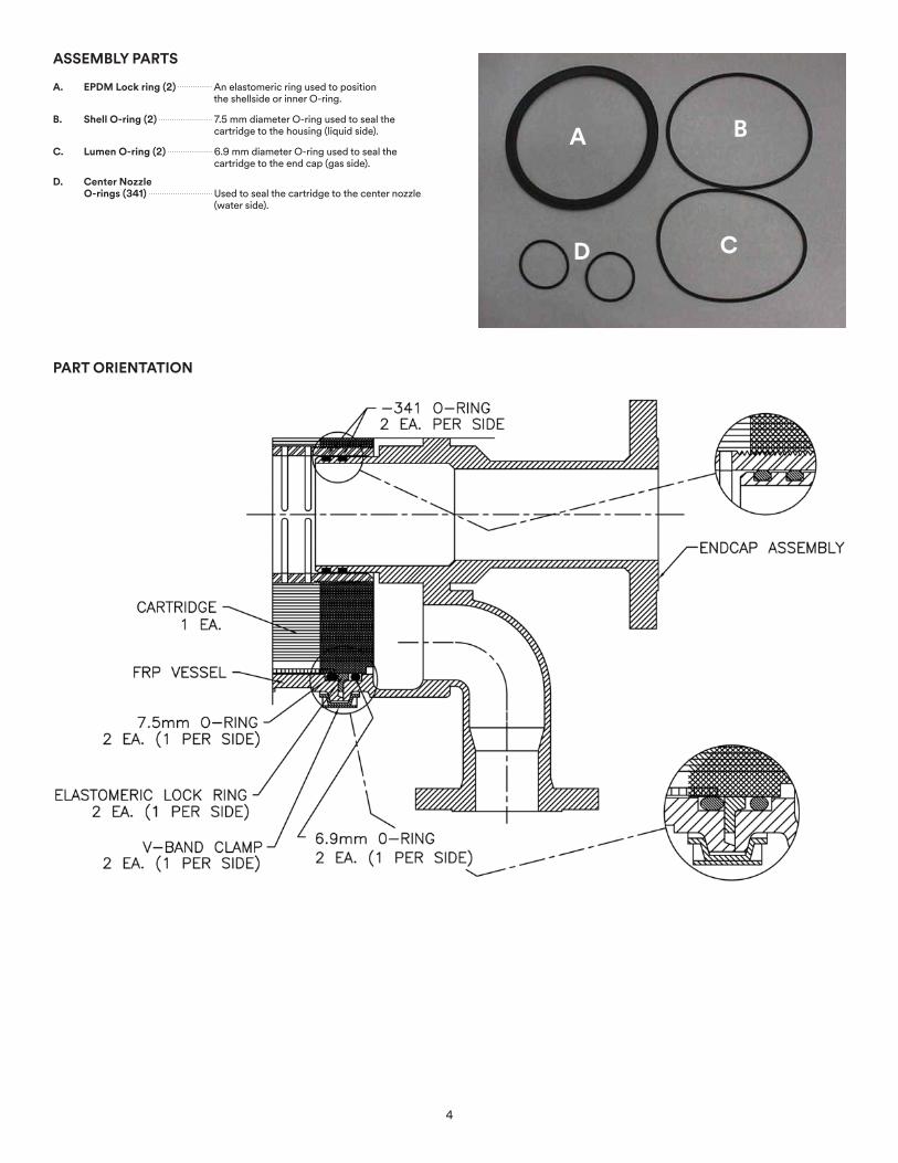
ASSEMBLY PARTS
A. EPDM Lock ring (2) An elastomeric ring used to position the shellside or inner O-ring.
B. Shell O-ring (2) 7.5 mm diameter O-ring used to seal the cartridge to the housing (liquid side).
C. Lumen O-ring (2) 6.9 mm diameter O-ring used to seal the cartridge to the end cap (gas side).
D. Center Nozzle O-rings (341) Used to seal the cartridge to the center nozzle
(water side).
PART ORIENTATION
B
C
A
D
4
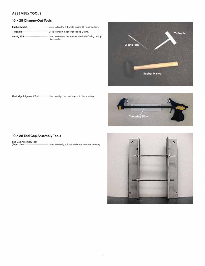
ASSEMBLY TOOLS
10 x 28 Change-Out Tools
Rubber Mallet Used to tap the T-handle during O-ring insertion.
T-Handle Used to insert inner or shellside O-ring.
O-ring Pick Used to remove the inner or shellside O-ring during disassembly.
Cartridge Alignment Tool Used to align the cartridge with the housing.
10 x 28 End Cap Assembly Tools
End Cap Assembly Tool (Front view) Used to evenly pull the end caps onto the housing.
Rubber Mallet
T-Handle
O-ring Pick
Centering Slide
5

End Cap Assembly Tool
(Back view)
10 x 28 End Cap Assembly Tools
Connecting Rods
(Set of 4)
The end cap assembly tool is packaged and shipped unassembled. Upon receipt, assemble as shown. Typically, hand tightening the nuts is adequate.
The equipment illustrated above is required for the assembly/disassembly of a 3M™ Liqui-Cel™ EXF-10x28 Series Membrane Contactor.
Support knobs
Rubber coating
6
END CAP REMOVAL
WARNING
To reduce the risks associated with crush or impact related injuries:
• Always ensure the membrane contactor is properly secured. Be sure the membrane contactor cannot tip, roll, fall, slide or make any movement that may cause injury or damage to other system components.
• No liquid, vacuum or sweep gas should be running through the contactor when changing cartridges or other parts. Membrane contactors should be completely drained of liquid before attempting to service.
• Care must be taken not to hit or jar (shock) the membrane contactor.
To reduce the risks associated with lifting or moving:
• Always consult the product datasheet or operating guide for membrane contactor weights. Use appropriately rated lifting equipment for lifting or moving heavy membrane contactors.
• Drain liquid from the contactor before moving. Do not move a membrane contactor while it contains liquid.
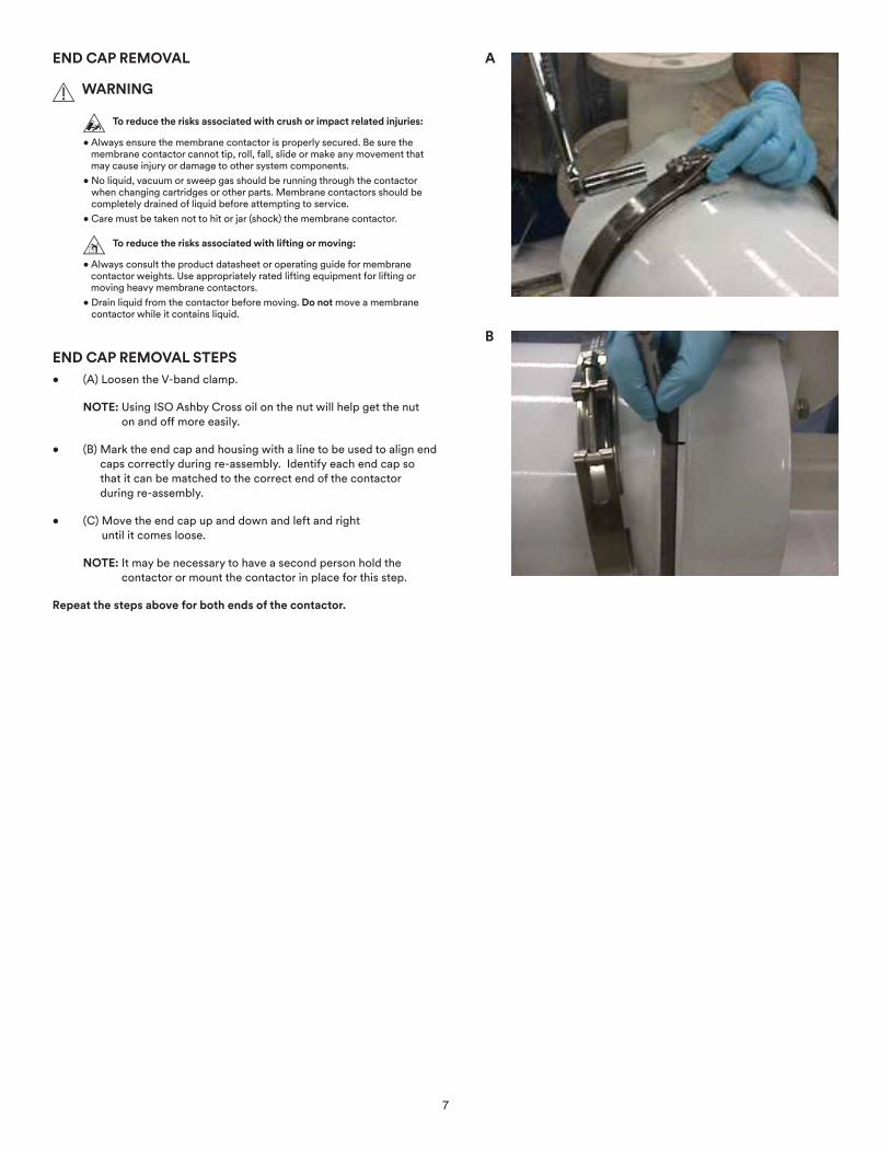
END CAP REMOVAL STEPS• (A) Loosen the V-band clamp.
NOTE: Using ISO Ashby Cross oil on the nut will help get the nut on and off more easily.
• (B) Mark the end cap and housing with a line to be used to align end caps correctly during re-assembly. Identify each end cap so that it can be matched to the correct end of the contactor during re-assembly.
• (C) Move the end cap up and down and left and right until it comes loose.
NOTE: It may be necessary to have a second person hold the contactor or mount the contactor in place for this step.
Repeat the steps above for both ends of the contactor.
A
B
7
CARTRIDGE REMOVAL
WARNING
To reduce the risks associated with explosion:
• Only use replacement parts supplied by 3M for this product.
To reduce the risks associated with crush or impact related injuries:
• Always ensure the membrane contactor is properly secured. Be sure the membrane contactor cannot tip, roll, fall, slide or make any movement that may cause injury or damage to other system components.
• Care must be taken not to hit or jar (shock) the membrane contactor.
To reduce the risks associated with lifting or moving:
• Always consult the product datasheet or operating guide for membrane contactor weights. Use appropriately rated lifting equipment for lifting or moving heavy membrane contactors.
NOTICE• To avoid contamination, gloves are recommended when handling the membrane
cartridges.
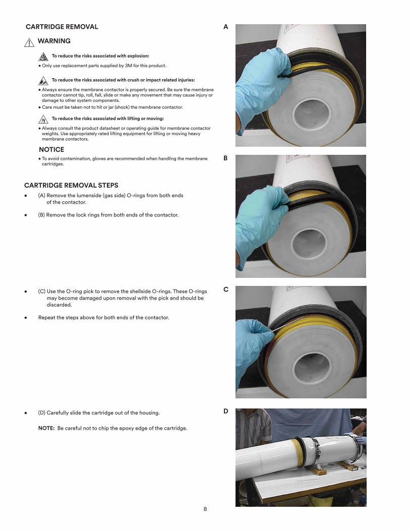
CARTRIDGE REMOVAL STEPS• (A) Remove the lumenside (gas side) O-rings from both ends
of the contactor.
• (B) Remove the lock rings from both ends of the contactor.
• (C) Use the O-ring pick to remove the shellside O-rings. These O-rings may become damaged upon removal with the pick and should be discarded.
• Repeat the steps above for both ends of the contactor.
• (D) Carefully slide the cartridge out of the housing.
NOTE: Be careful not to chip the epoxy edge of the cartridge.
A
B
C
D
8
CARTRIDGE INSERTION
WARNING
To reduce the risks associated with explosion:
• Only use replacement parts supplied by 3M for this product.
To reduce the risks associated with crush or impact related injuries:
• Always ensure the membrane contactor is properly secured. Be sure the membrane contactor cannot tip, roll, fall, slide or make any movement that may cause injury or damage to other system components.
• Care must be taken not to hit or jar (shock) the membrane contactor.
To reduce the risks associated with lifting or moving:
• Always consult the product datasheet or operating guide for membrane contactor weights. Use appropriately rated lifting equipment for lifting or moving heavy membrane contactors.
NOTICE• To avoid contamination, gloves are recommended when handling the
membrane cartridges.
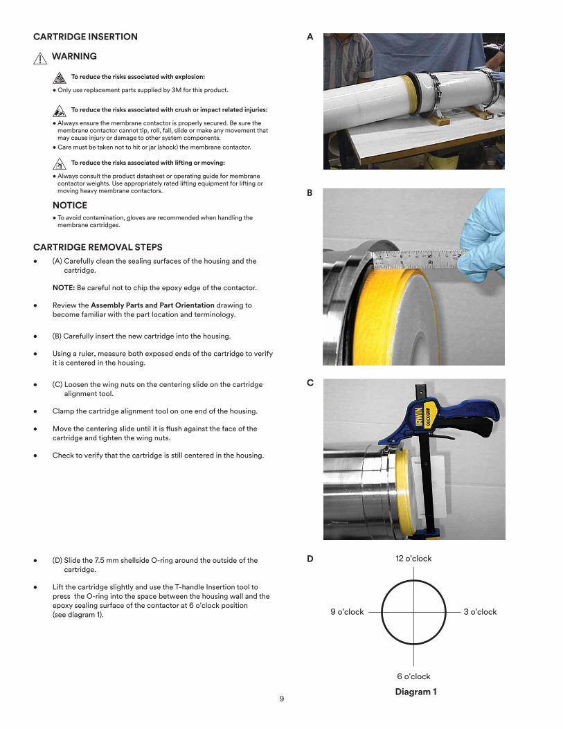
CARTRIDGE REMOVAL STEPS• (A) Carefully clean the sealing surfaces of the housing and the
cartridge.
NOTE: Be careful not to chip the epoxy edge of the contactor.
• Review the Assembly Parts and Part Orientation drawing to become familiar with the part location and terminology.
• (B) Carefully insert the new cartridge into the housing.
• Using a ruler, measure both exposed ends of the cartridge to verify it is centered in the housing.
• (C) Loosen the wing nuts on the centering slide on the cartridge alignment tool.
• Clamp the cartridge alignment tool on one end of the housing.
• Move the centering slide until it is flush against the face of the cartridge and tighten the wing nuts.
• Check to verify that the cartridge is still centered in the housing.
• (D) Slide the 7.5 mm shellside O-ring around the outside of the cartridge.
• Lift the cartridge slightly and use the T-handle Insertion tool to press the O-ring into the space between the housing wall and the epoxy sealing surface of the contactor at 6 o'clock position (see diagram 1).
A
B
C
D
Diagram 1
12 o'clock
6 o'clock
3 o'clock9 o'clock
9
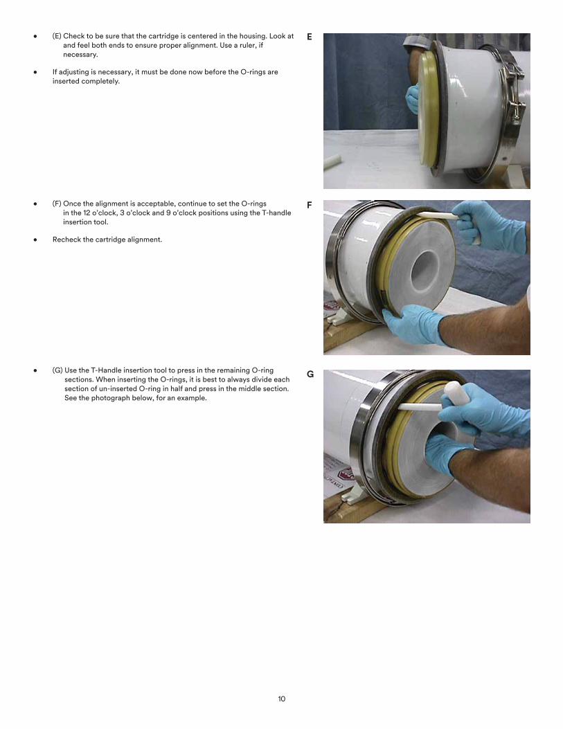
• (E) Check to be sure that the cartridge is centered in the housing. Look at and feel both ends to ensure proper alignment. Use a ruler, if necessary.
• If adjusting is necessary, it must be done now before the O-rings are inserted completely.
• (F) Once the alignment is acceptable, continue to set the O-rings in the 12 o’clock, 3 o’clock and 9 o’clock positions using the T-handle insertion tool.
• Recheck the cartridge alignment.
• (G) Use the T-Handle insertion tool to press in the remaining O-ring sections. When inserting the O-rings, it is best to always divide each section of un-inserted O-ring in half and press in the middle section. See the photograph below, for an example.
E
F
G
10
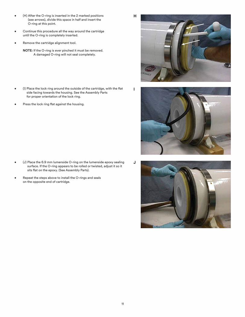
• (H) After the O-ring is inserted in the 2 marked positions (see arrows), divide this space in half and insert the O-ring at this point.
• Continue this procedure all the way around the cartridge until the O-ring is completely inserted.
• Remove the cartridge alignment tool.
NOTE: If the O-ring is ever pinched it must be removed. A damaged O-ring will not seal completely.
• (I) Place the lock ring around the outside of the cartridge, with the flat side facing towards the housing. See the Assembly Parts for proper orientation of the lock ring.
• Press the lock ring flat against the housing.
• (J) Place the 6.9 mm lumenside O-ring on the lumenside epoxy sealing surface. If the O-ring appears to be rolled or twisted, adjust it so it sits flat on the epoxy. (See Assembly Parts).
• Repeat the steps above to install the O-rings and seals on the opposite end of cartridge.
H
I
J
11
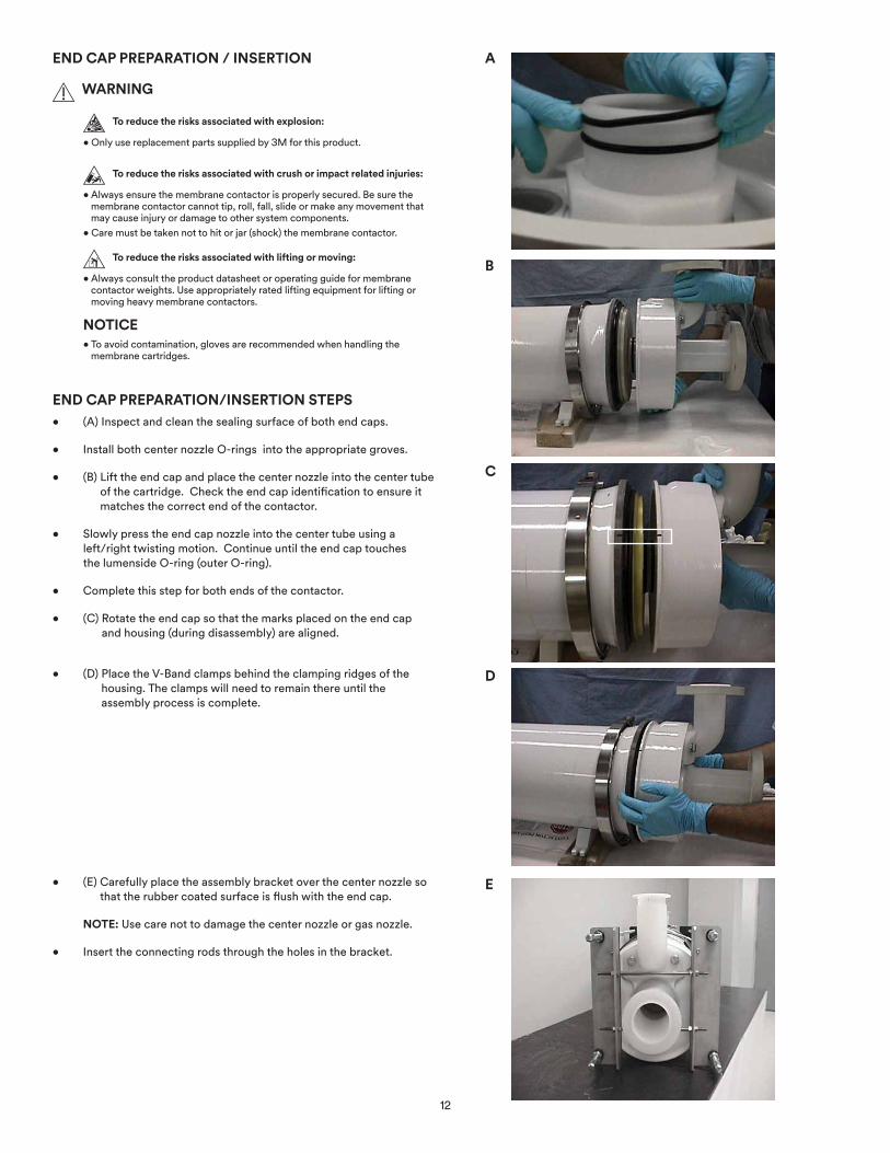
END CAP PREPARATION / INSERTION
WARNING
To reduce the risks associated with explosion:
• Only use replacement parts supplied by 3M for this product.
To reduce the risks associated with crush or impact related injuries:
• Always ensure the membrane contactor is properly secured. Be sure the membrane contactor cannot tip, roll, fall, slide or make any movement that may cause injury or damage to other system components.
• Care must be taken not to hit or jar (shock) the membrane contactor.
To reduce the risks associated with lifting or moving:
• Always consult the product datasheet or operating guide for membrane contactor weights. Use appropriately rated lifting equipment for lifting or moving heavy membrane contactors.
NOTICE• To avoid contamination, gloves are recommended when handling the
membrane cartridges.
END CAP PREPARATION/INSERTION STEPS• (A) Inspect and clean the sealing surface of both end caps.
• Install both center nozzle O-rings into the appropriate groves.
• (B) Lift the end cap and place the center nozzle into the center tube of the cartridge. Check the end cap identification to ensure it matches the correct end of the contactor.
• Slowly press the end cap nozzle into the center tube using a left/right twisting motion. Continue until the end cap touches the lumenside O-ring (outer O-ring).
• Complete this step for both ends of the contactor.
• (C) Rotate the end cap so that the marks placed on the end cap and housing (during disassembly) are aligned.
• (D) Place the V-Band clamps behind the clamping ridges of the housing. The clamps will need to remain there until the assembly process is complete.
• (E) Carefully place the assembly bracket over the center nozzle so that the rubber coated surface is flush with the end cap.
NOTE: Use care not to damage the center nozzle or gas nozzle.
• Insert the connecting rods through the holes in the bracket.
A
B
C
D
E
12

• (F) The assembly bracket should be placed on the end cap so that the support knobs rest on the edge of the end cap. This will prevent the bracket cross bars from contacting the center nozzle.
• Repeat these steps for both assembly brackets.
• (G) Join both halves of the connecting rods with the center nut.
• (H) Fully assembled bracket.
• (I) Tighten the assembly bracket nuts (2 rotations maximum at a
time) to pull the end caps onto the cartridge. Tighten in an even manner that will allow the end cap to progress slowly and evenly.
• It will be necessary to do the tightening at both ends of the assembly bracket during the installation process.
F
G
H
I
Support knobs
13

• (J) Look Into the center nozzle.
• (K) At this point you can see the center nozzle O-rings. The O-rings
should appear as two dark parallel circles all the way around the inner circumference of the center nozzle. If an O-ring is pinched or twisted, it will need to be discarded and replaced.
• (L) While the end cap is pulled tight against the housing, place the
V-Band clamp on the ridge of the housing and the end cap and tighten the clamp.
NOTE: Using ISO Ashby Cross oil on the nut will help get the nut on and off more easily.
• Repeat for both sides.
J
K
L
O-rings
14

• (M) Loosen the connecting rods of the assembly tool and disconnect the tool from the housing.
• The contactor is now fully assembled.
PRESSURE TEST• (N) Bolt blind flanges on both lumen ports and one of the shell
ports.
• Bolt a flange equipped with a 0-100 psig gauge and hose connection.
• Pressurize the housing to 60 psig with clean oil free air.
• Isolate the pressurized housing and monitor the pressure to assure a leak free seal. Maximum pressure decay should be ≤0.1 psi over 30 minutes.
M
N
Compressed Air Source
15
LC-1089Rev. 03/2017
3M.com/Liqui-Cel
Technical Information: The technical information, recommendations and other statements contained in this document are based upon tests or experience that 3M believes are reliable, but the accuracy or completeness of such information is not guaranteed.
Product Use: Many factors beyond 3M’s control and uniquely within user’s knowledge and control can affect the use and performance of a 3M product in a particular application. Given the variety of factors that can affect the use and performance of a 3M product, user is solely responsible for evaluating the 3M product and determining whether it is fit for a particular purpose and suitable for user’s method of application.
Warranty, Limited Remedy, and Disclaimer: Unless an additional warranty is specifically stated on the applicable 3M product packaging or product literature, 3M warrants that each 3M product meets the applicable 3M product specification at the time 3M ships the product. 3M MAKES NO OTHER WARRANTIES OR CONDITIONS, EXPRESS OR IMPLIED, INCLUDING, BUT NOT LIMITED TO, ANY IMPLIED WARRANTY OR CONDITION OF MERCHANTABILITY OR FITNESS FOR A PARTICULAR PURPOSE OR ANY IMPLIED WARRANTY OR CONDITION ARISING OUT OF A COURSE OF DEALING, CUSTOM OR USAGE OF TRADE. If the 3M product does not conform to this warranty, then the sole and exclusive remedy is, at 3M’s option, replacement of the 3M product or refund of the purchase price.
Limitation of Liability: Except where prohibited by law, 3M will not be liable for any loss or damage arising from the 3M product, whether direct, indirect, special, incidental or consequential, regardless of the legal theory asserted, including warranty, contract, negligence or strict liability.
3M and Liqui-Cel are trademarks of 3M Company. All other trademarks are the property of their respective owners. © 2017 3M Company. All rights reserved.
3M Deutschland GmbH Separation and Purification Sciences Division Öhder Straße 28 42289 Wuppertal Germany Phone: +49 202 6099 - 0 Fax: +49 202 6099 - 241
Separation and Purification Sciences Division 13840 South Lakes Drive Charlotte, North Carolina 28273 USA Phone: +1 980 859 5400