3gpp ts 43.129
DESCRIPTION
3GPP TS 43.129TRANSCRIPT
3GPP TS 43.129 V8.2.0 (2009-11)Technical Specification
3rd Generation Partnership Project;Technical Specification Group GSM/EDGE
Radio Access Network;Packet-switched handover for GERAN A/Gb mode;
Stage 2(Release 8)
GLOBAL SYSTEM FOR
MOBILE COMMUNICATIONS
R
The present document has been developed within the 3rdGeneration Partnership Project (3GPP
TM) and may be further elaborated for the purposes of 3GPP.
The present document has not been subject to any approval process by the 3GPPOrganizational Partners and shall not be implemented.
This Specification is provided for future development work within 3GPP only. The Organizational Partners accept no liability for any use of this Specification.Specifications and reports for implementation of the 3GPP
TMsystem should be obtained via the 3GPP Organizational Partners' Publications Offices.
3GPP
3GPP TS 43.129 V8.2.0 (2009-11)2Release 8
Keywords
GSM, handover, packet-mode
3GPP
Postal address
3GPP support office address
650 Route des Lucioles - Sophia AntipolisValbonne - FRANCE
Tel.: +33 4 92 94 42 00 Fax: +33 4 93 65 47 16
Internet
http://www.3gpp.org
Copyright Notification
No part may be reproduced except as authorized by written permission.
The copyright and the foregoing restriction extend to reproduction in all media.
© 2009, 3GPP Organizational Partners (ARIB, ATIS, CCSA, ETSI, TTA, TTC).
All rights reserved.
UMTS™ is a Trade Mark of ETSI registered for the benefit of its members3GPP™ is a Trade Mark of ETSI registered for the benefit of its Members and of the 3GPP Organizational PartnersLTE™ is a Trade Mark of ETSI currently being registered for the benefit of its Members and of the 3GPP Organizational PartnersGSM® and the GSM logo are registered and owned by the GSM Association
3GPP
3GPP TS 43.129 V8.2.0 (2009-11)3Release 8
Contents
Foreword ......................................................................................................................................................7
Introduction ..................................................................................................................................................7
1 Scope..................................................................................................................................................8
2 References ..........................................................................................................................................8
3 Definitions and abbreviations ..............................................................................................................93.1 Definitions...................................................................................................................................................9
3.2 Void ..........................................................................................................................................................10
3.3 Abbreviations.............................................................................................................................................10
4 Architecture and principles ...............................................................................................................124.1 Reference architecture................................................................................................................................12
4.2 Handover principles ...................................................................................................................................12
4.2.1 General.................................................................................................................................................12
4.2.2 PS Handover preparation phase.............................................................................................................13
4.2.3 PS Handover execution phase ...............................................................................................................14
4.2.4 PS Handover Network Node Responsibilities ........................................................................................14
4.3 Protocol architecture ..................................................................................................................................14
4.3.1 User plane overview .............................................................................................................................14
4.3.2 Control plane overview.........................................................................................................................14
4.3.3 Physical Layer ......................................................................................................................................15
4.3.3.1 Shared Channels..............................................................................................................................154.3.3.1.1 General......................................................................................................................................15
4.3.4 RLC/MAC............................................................................................................................................15
4.3.5 Radio Resource (RR) ............................................................................................................................16
4.3.6 BSSGP .................................................................................................................................................16
4.3.7 Overview of PS Handover Signalling Messages ....................................................................................16
4.3.7.1 PS handover signalling messages on the Um interface......................................................................16
4.3.7.2 PS handover signalling messages on the Gb interface.......................................................................16
4.3.7.3 PS handover signalling messages on the Gn interface.......................................................................17
4.3.7.4 PS handover signalling messages on the Up interface.......................................................................18
4.4 Identifiers ..................................................................................................................................................18
4.4.1 NSAPI, PFI, RAB ID relation during inter-RAT, inter-mode UTRAN/GERAN Iu PS handover.............19
4.4.2 NSAPI, PFI, EPS Bearer ID relation during inter-RAT GERAN / E-UTRAN PS handover ...................20
5 Signalling procedures........................................................................................................................205.1 GERAN (A/Gb mode) GERAN (A/Gb mode) handover .........................................................................20
5.1.1 Intra Cell ..............................................................................................................................................20
5.1.2 Intra BSS..............................................................................................................................................21
5.1.2.1 General ...........................................................................................................................................21
5.1.2.2 Intra BSS HO; Preparation phase .....................................................................................................21
5.1.2.3 Intra BSS HO; Execution phase .......................................................................................................22
5.1.2.4 Intra BSS Handover - Optimised......................................................................................................23
5.1.3 Intra SGSN...........................................................................................................................................255.1.3.1 Intra SGSN/Inter BSS HO, Preparation phase ..................................................................................25
5.1.3.2 Intra SGSN/Inter BSS HO, Execution phase ....................................................................................26
5.1.4 Inter SGSN...........................................................................................................................................28
5.1.4.1 Inter SGSN HO, Preparation phase ..................................................................................................28
5.1.4.2 Inter SGSN HO, Execution phase ....................................................................................................31
5.2 Inter-RAT/mode handover (GERAN A/Gb mode UTRAN/ GERAN Iu mode)........................................35
5.2.1 Intra SGSN...........................................................................................................................................35
5.2.1.1 Intra-SGSN GERAN A/Gb mode to UTRAN/GERAN Iu mode HO; Preparation phase ....................35
5.2.1.2 Intra-SGSN GERAN A/Gb mode to UTRAN/GERAN Iu mode HO; Execution phase ......................37
5.2.2 Inter SGSN...........................................................................................................................................40
5.2.2.1 Inter-SGSN GERAN A/Gb mode to UTRAN/GERAN Iu mode HO; Preparation phase ....................405.2.2.2 Inter-SGSN GERAN A/Gb mode to UTRAN/GERAN Iu mode HO; Execution phase ......................42
3GPP
3GPP TS 43.129 V8.2.0 (2009-11)4Release 8
5.3 Inter-RAT/mode Handover (UTRAN/GERAN Iu mode GERAN A/Gb mode)........................................46
5.3.1 Intra SGSN...........................................................................................................................................46
5.3.1.1 Inter RAT/mode UTRAN/GERAN Iu mode to GERAN A/Gb mode PS HO; Preparation phase........46
5.3.1.2 Inter RAT/mode UTRAN/GERAN Iu mode to GERAN A/Gb mode PS HO; Execution phase..........48
5.3.2 Inter SGSN...........................................................................................................................................51
5.3.2.1 Inter RAT/mode UTRAN/GERAN Iu mode to GERAN A/Gb mode PS HO; Preparation phase........515.3.2.2 Inter RAT UTRAN/GERAN Iu mode to GERAN A/Gb mode PS HO; Execution phase ...................53
5.3a Inter-RAT Handover (GERAN A/Gb mode to E-UTRAN) ..........................................................................56
5.3a.1 General.................................................................................................................................................56
5.3a.2 Preparation phase..................................................................................................................................57
5.3a.3 Execution phase....................................................................................................................................57
5.3b Inter-RAT Handover (E-UTRAN to GERAN A/Gb mode) ..........................................................................57
5.3b.1 General.................................................................................................................................................57
5.3b.2 Preparation phase..................................................................................................................................57
5.3b.3 Execution phase....................................................................................................................................57
5.4 Handover reject..........................................................................................................................................58
5.4.1 General.................................................................................................................................................58
5.4.2 Inter-SGSN HO Reject; Signalling procedure........................................................................................585.5 Handover cancel ........................................................................................................................................58
5.5.1 General.................................................................................................................................................58
5.5.2 Signalling procedures............................................................................................................................59
5.5.2.1 Inter-SGSN case, GERAN A/Gb mode GERAN A/Gb mode........................................................59
5.5.2.2 Inter-SGSN case, GERAN A/Gb mode UTRAN/GERAN Iu mode...............................................60
5.5.2.3 Inter-SGSN case, UTRAN/GERAN Iu mode GERAN A/Gb mode...............................................61
5.5.2.4 Inter-SGSN, GERAN A/Gb mode E-UTRAN.............................................................................................61
5.5.2.5 Inter-SGSN case, E - UTRAN GERAN A/Gb mode ....................................................................................61
5.6 Container handling.....................................................................................................................................61
5.6.1 Contents of the containers.....................................................................................................................63
5.6.1.1 Contents of the GERAN A/Gb mode or GAN mode GERAN A/Gb mode TransparentContainers.......................................................................................................................................64
5.6.1.1.1 Source BSS to Target BSS Transparent Container ......................................................................64
5.6.1.1.2 Target BSS to Source BSS Transparent Container ......................................................................64
5.6.1.2 Contents of the GERAN A/Gb mode or GAN mode UTRAN Transparent Containers..................64
5.6.1.2.1 Source to Target Transparent Container......................................................................................64
5.6.1.2.2 Target to Source Transparent Container......................................................................................65
5.6.1.3 Contents of the UTRAN GERAN A/Gb Mode or GAN mode Transparent Containers .................65
5.6.1.3.1 Source BSS to Target BSS Transparent Container ......................................................................65
5.6.1.3.2 Target BSS to Source BSS Transparent Container ......................................................................65
5.6.1.4 Contents of the GERAN A/Gb mode GERAN Iu mode Transparent Containers...........................66
5.6.1.4.1 Source to Target Transparent Container......................................................................................66
5.6.1.4.2 Target to Source Transparent Container......................................................................................665.6.1.5 Content of GERAN Iu mode GERAN A/Gb mode Transparent Containers..................................66
5.6.1.5.1 Source BSS to Target BSS Transparent Container ......................................................................66
5.6.1.5.2 Target BSS to Source BSS Transparent Container ......................................................................66
5.6.1.6 Contents of the GERAN A/Gb mode GAN mode Transparent Containers....................................67
5.6.1.6.1 Source BSS to Target BSS Transparent Container ......................................................................67
5.6.1.6.2 Target BSS to Source BSS Transparent Container ......................................................................67
5.6.1.7 Contents of the GERAN A/Gb mode E-UTRAN Transparent Containers.....................................67
5.6.1.7.1 Source to Target Transparent Container....................................................................................67
5.6.1.7.2 Target to Source Transparent Container....................................................................................67
5.6.1.8 Contents of the E-UTRAN GERAN A/Gb mode Transparent Containers ....................................68
5.6.1.8.1 Source BSS to Target BSS Transparent Container ......................................................................685.6.1.8.2 Target BSS to Source BSS Transparent Container ......................................................................68
5.7 PS Handover Failure ..................................................................................................................................68
5.7.1 Preparations Phase Failure Scenarios.....................................................................................................69
5.7.1.1 PS Handover preparation phase failure scenarios on the Um interface ..............................................69
5.7.1.2 PS Handover preparation phase failure scenarios on the Gb interface ...............................................69
5.7.1.3 PS Handover preparation phase failure scenarios on the Gn interface ...............................................69
5.7.1.4 PS Handover preparation phase failure scenarios on the Up interface ...............................................69
5.7.2 Execution Phase Failure Scenarios ........................................................................................................70
5.7.2.1 Execution phase failures on the Um interface...................................................................................70
5.7.2.1.1 Initial Access Failure in the Target Cell during PS handover .......................................................70
3GPP
3GPP TS 43.129 V8.2.0 (2009-11)5Release 8
5.7.2.1.2 Radio contact with the MS is lost: ..............................................................................................71
5.7.2.2 Execution phase failures on the Gb interface ....................................................................................73
5.7.2.3 Execution phase failures on the Gn interface ....................................................................................74
5.8 GAN Handover ..........................................................................................................................................74
5.8.1 Intra-SGSN Handover (GERAN A/Gb mode GAN mode handover) .................................................74
5.8.1.1 Intra SGSN PS Handover, Preparation phase....................................................................................745.8.1.2 Intra SGSN PS Handover, Execution phase......................................................................................75
5.8.2 Intra-SGSN Handover (GAN mode GERAN A/Gb mode handover) .................................................75
5.8.2.1 Intra SGSN PS Handover, Preparation phase....................................................................................75
5.8.2.2 Intra SGSN PS Handover, Execution phase......................................................................................76
5.8.3 Inter-SGSN Handover (GERAN A/Gb mode GAN mode handover) .................................................76
5.8.3.1 Inter SGSN PS Handover, Preparation phase....................................................................................76
5.8.3.2 Inter SGSN PS Handover, Execution phase......................................................................................76
5.8.4 Inter-SGSN Handover (GAN mode GERAN A/Gb mode handover) .................................................76
5.8.4.1 Inter SGSN PS Handover, Preparation phase....................................................................................76
5.8.4.2 Inter SGSN, Execution phase...........................................................................................................77
5.8.5 Inter RAT Handover; Intra SGSN (UTRAN GAN mode handover)...................................................77
5.8.5.1 Intra SGSN PS Handover, Preparation phase....................................................................................775.8.5.2 Intra SGSN PS Handover, Execution phase.....................................................................................78
5.8.6 Inter RAT Handover; Intra SGSN (GAN mode UTRAN handover)....................................................78
5.8.6.1 Intra SGSN PS Handover, Preparation phase....................................................................................78
5.8.6.2 Intra SGSN, Execution phase...........................................................................................................78
5.8.7 Inter RAT Handover; Inter SGSN (UTRAN GAN mode handover)...................................................79
5.8.7.1 Inter SGSN PS Handover, Preparation phase....................................................................................79
5.8.7.2 Inter SGSN PS Handover, Execution phase......................................................................................79
5.8.8 Inter RAT Handover; Inter SGSN (GAN mode UTRAN handover)...................................................79
5.8.8.1 Inter SGSN PS Handover, Preparation phase....................................................................................79
5.8.8.2 Inter SGSN PS Handover, Execution phase......................................................................................79
6 Radio interface Signalling .................................................................................................................796.1 PS Handover Signalling (Um) ....................................................................................................................79
6.1.1 General.................................................................................................................................................79
6.1.2 Overview of PS Handover messages .....................................................................................................80
6.1.2.1 GERAN A/Gb mode/GAN mode to GERAN A/Gb mode PS Handover ...........................................80
6.1.2.2 UTRAN/GERAN Iu mode to GERAN A/Gb mode/GAN mode PS Handover ..................................80
6.1.2.3 GERAN A/Gb mode to GERAN Iu mode PS Handover ...................................................................81
6.1.2.4 GERAN A/Gb mode/GAN mode to UTRAN mode PS Handover.....................................................82
6.1.2.5 GERAN A/Gb mode to GAN mode PS Handover ............................................................................82
6.1.2.6 GERAN A/Gb mode to E-UTRAN PS Handover .............................................................................826.1.2.7 E-UTRAN to GERAN A/Gb mode PS Handover .............................................................................83
6.1.3 RLC/MAC segmentation ......................................................................................................................83
6.1.4 Inter RAT/mode PS Handover to GERAN A/Gb ...................................................................................83
6.1.5 Inter RAT/mode PS Handover from GERAN A/Gb...............................................................................83
6.2 Mechanisms for Initial Access in the Target Cell ........................................................................................83
6.2.1 General.................................................................................................................................................83
6.2.2 Synchronisation of handovers ...............................................................................................................84
6.2.3 Option 1 - Downlink Data sent after performing access in the target cell................................................84
6.2.3.1 Unsynchronised Networks Call Flow...............................................................................................84
6.2.3.2 Synchronised Networks Call Flow...................................................................................................85
6.2.4 Option 2 - Downlink Data sent before performing access in the target cell (Blind Transmission)............85
6.2.4.1 Unsynchronised Networks Call Flow...............................................................................................866.2.4.2 Synchronised Network Call Flow ....................................................................................................86
6.3 Methods for triggering PS Handover ..........................................................................................................87
Annex A (normative): Agreed handover principles.......................................................................88
A.1 Agreed handover principles...............................................................................................................88
Annex B (informative): PS Handover Primitives.............................................................................90
B.1 Overview ..........................................................................................................................................90
B.2 Primitives in Source BSS ................................................................................................................90
3GPP
3GPP TS 43.129 V8.2.0 (2009-11)6Release 8
B.3 Primitives in Old SGSN..................................................................................................................91
B.5 Primitives in Target BSS.................................................................................................................93
B.6 Primitives in MS .............................................................................................................................93
Annex C (informative): Change history ...........................................................................................94
3GPP
3GPP TS 43.129 V8.2.0 (2009-11)7Release 8
Foreword
This Technical Specification has been produced by the 3rd Generation Partnership Project (3GPP).
The contents of the present document are subject to continuing work within the TSG and may change following formal
TSG approval. Should the TSG modify the contents of the present document, it will be re-released by the TSG with an
identifying change of release date and an increase in version number as follows:
Version x.y.z
where:
x the first digit:
1 presented to TSG for information;
2 presented to TSG for approval;
3 or greater indicates TSG approved document under change control.
y the second digit is incremented for all changes of substance, i.e. technical enhancements, corrections,
updates, etc.
z the third digit is incremented when editorial only changes have been incorporated in the document.
Introduction
Packet Switched (PS) handover is introduced in order to support real-time packet-switched with strict QoS requirements
on low latency and packet loss. Packet switched handover reduces the service interruption of the user plane information
at cell change compared to the cell-reselection and enables methods to improve buffer handling of user plane data in
order to reduce packet loss at cell-change.
3GPP
3GPP TS 43.129 V8.2.0 (2009-11)8Release 8
1 Scope
The present document defines the stage-2 service description for packet switched handover in GERAN A/Gb mode and
GAN mode. ITU-T Recommendation I.130 [8] describes a three-stage method for characterisation of
telecommunication services, and ITU-T Recommendation Q.65 [9] defines stage 2 of the method. The present
document refers to packet switched handover in GERAN A/Gb mode/GAN mode, and therefore focuses on the
corresponding radio protocol enhancements to the packet switched domain only i.e. when services are provided through
the Gb interface.
2 References
The following documents contain provisions which, through reference in this text, constitute provisions of the present
document.
References are either specific (identified by date of publication, edition number, version number, etc.) or
non-specific.
For a specific reference, subsequent revisions do not apply.
For a non-specific reference, the latest version applies. In the case of a reference to a 3GPP document (including
a GSM document), a non-specific reference implicitly refers to the latest version of that document in the same
Release as the present document.
[1] 3GPP TR 21.905: "Vocabulary for 3GPP Specifications".
[2] 3GPP TS 22.105: "Services and service capabilities".
[3] 3GPP TS 22.060: "General Packet Radio Service (GPRS); Service description; Stage 1".
[4] 3GPP TS 43.064: "Overall description of the GPRS radio interface; Stage 2".
[5] 3GPP TS 25.922: "Radio Resource Management strategies".
[6] 3GPP TS 23.107: "Quality of Service (QoS) concept and architecture".
[7] 3GPP TS 44.060: "General Packet Radio Service (GPRS); Mobile Station (MS) - Base Station
System (BSS) interface; Radio Link Control/Medium Access Control (RLC/MAC) protocol".
[8] ITU-T Recommendations I.130: "Method for the characterization of telecommunication services
supported by an ISDN and network capabilities of an ISDN".
[9] ITU-T Recommendation Q.65: "The unified functional methodology for the characterization of
services and network capabilities".
[10] 3GPP TS 48.018: "General Packet Radio Service (GPRS); Base Station System (BSS) - Serving
GPRS Support Node (SGSN); BSS GPRS Protocol".
[11] 3GPP TS 29.060: "General Packet Radio Service (GPRS); GPRS Tunnelling Protocol (GTP)
across the Gn and Gp interface".
[12] 3GPP TS 23.003: "Numbering, addressing and identification".
[13] 3GPP TS 25.401: "UTRAN overall description".
[14] 3GPP TS 43.051: "GSM/EDGE Radio Access Network (GERAN) overall description; Stage 2".
[15] 3GPP TS 24.008: "Mobile radio interface Layer 3 specification; Core network protocols; Stage 3".
[16] 3GPP TS 44.118: "Mobile radio interface layer 3 specification, Radio Resource Control (RRC)
protocol; Iu mode".
3GPP
3GPP TS 43.129 V8.2.0 (2009-11)9Release 8
[17] 3GPP TS 25.331: "Radio Resource Control (RRC) protocol specification".
[18] 3GPP TS 24.007: "Mobile radio interface signalling layer 3; General Aspects".
[19] 3GPP TS 23.060: "General Packet Radio Service (GPRS); Service description; Stage 2".
[20] 3GPP TS 23.108: "Mobile radio interface layer 3 specification core network protocols; Stage 2
(structured procedures)".
[21] 3GPP TS 44.064: "Mobile Station - Serving GPRS Support Node (MS-SGSN) Logical LinkControl (LLC) Layer Specification".
[22] 3GPP TS 23.236: "Intra-domain connection of Radio Access Network (RAN) nodes to multiple
Core Network (CN) nodes".
[23] 3GPP TS 25.413: "UTRAN Iu interface Radio Access Network Application Part (RANAP)
signalling".
[24] Void.
[25] 3GPP TS 44.018: "Mobile radio interface layer 3 specification; Radio Resource Control (RRC)
protocol".
[26] 3GPP TS 45.010: "Radio subsystem synchronization".
[27] 3GPP TS 33.102: “Security architecture”.
[28] 3GPP TS 44.318: “Generic access to the A/Gb interface; Mobile GA interface layer 3
specification”.
[29] 3GPP TS 43.318: “Generic access to the A/Gb interface; Stage 2”.
[30] 3GPP TS 36.300: “Evolved Universal Terrestrial Radio Access (E-UTRA) and Evolved Universal
Terrestrial Radio Access (E-UTRAN); Overall description; Stage 2”.
[31] 3GPP TS 36.331:” Evolved Universal Terrestrial Radio Access (E-UTRA); Radio Resource
Control (RRC); Protocol specification”.
[32] 3GPP TS 36.401: “Evolved Universal Terrestrial Radio Access Network (E-UTRAN);
Architecture description”.
[33] 3GPP TS 23.401: “General Packet Radio Service (GPRS) enhancements for Evolved Universal
Terrestrial Radio Access Network (E-UTRAN) access”.
[34] 3GPP TS 36.413: "Evolved Universal Terrestrial Radio Access (E-UTRA); S1 Application
Protocol (S1AP)".
[35] 3GPP TS 24.301: “Non-Access-Stratum (NAS) protocol for Evolved Packet System (EPS); Stage
3”.
3 Definitions and abbreviations
3.1 Definitions
For the purposes of the present document, the terms and definitions given in 3GPP TR 21.905 [1] and the following
apply:
Active PFCs: that subset of the PFCs to be handed over, for which the source BSS has determined that resources
should be allocated in the target cell during the PS Handover preparation phase.
A/Gbmode:MS mode operation where the MS is connected to the Core Network via GERAN and the A and/or Gb
interfaces.
3GPP
3GPP TS 43.129 V8.2.0 (2009-11)10Release 8
Blind Transmission: refers to the decision made by the SGSN to start the transmission of downlink N-PDUs or by the
target BSS/GANC to start the transmission of downlink LLC PDUs for a given mobile station before receiving
confirmation that the PS handover procedure has been successfully completed.
GANMode:MS mode of operation where the MS is connected to the Core Network via a GANC and the A and/or Gb
interfaces.
PFC subject to handover: refers to an MS’s PFC for which the packet switched handover procedure is to be initiatedwhen a cell change is required. Whether a PFC needs handover or not is decided by the BSS. This decision criteria is
not standardized.
Source to Target Transparent Container: This container is encoded as "Source RNC to Target RNC transparent
container" in case of PS handover to UTRAN and as "Source eNB to Target eNB transparent container" in case of PS
handover to E-UTRAN. It replaces the "Source RNC to Target RNC Transparent container" used in previous releases.
Target to Source Transparent Container: This container is encoded as "Target RNC to Source RNC transparent
container" in case of PS handover to UTRAN and as "Target eNB to Source eNB transparent container" in case of PS
handover to E-UTRAN. It replaces the "Target RNC to Source RNC Transparent container" used in previous releases.
3.2 Void
3.3 Abbreviations
For the purposes of the present document, the following abbreviations apply:
ATM Asynchronous Transfer Mode
BSC Base Station Controller
BSS Base Station Sub-system
BSSGP Base Station Subsystem GPRS Protocol
BTS Base Transceiver Station
CN part Core Network partCN Core Network
CS Circuit Switched
DTI Direct Tunnel Indicator
DTM Dual Transfer Mode
EDGE Enhanced Data rates for GSM Evolution
eNB E-UTRAN NodeB
EPC Evolved Packet Core
EPS Evolved Packet System
E-UTRA Evolved UTRA
E-UTRAN Evolved UTRAN
FLO Flexible Layer One
GAN Generic Access NetworkGANC Generic Access Network Controller
GboIP Gb over IP
GCSI GPRS CAMEL Subscriber information indicator
GERAN GSM/EDGE Radio Access Network
GPRS General Packet Radio Service
GSM Global System for Mobile communications
GTP GPRS Tunnelling Protocol
IMS IPMultimedia Subsystem
IP Internet Protocol
LLC Logical Link Control
MAC Medium Access ControlMME Mobility Management Entity
MS Mobile Station
MSC Mobile Switching Centre
MTU Maximum Transfer Unit
PDP Packet Data Protocol
PDTCH Packet Data Traffic CHannel
PFC Packet Flow Context
3GPP
3GPP TS 43.129 V8.2.0 (2009-11)11Release 8
PFM Packet Flow Management
PS Packet Switched
PTCCH Packet Timing advance Control CHannel
QoS Quality of Service
RAB Radio Access Bearer
RAN Radio Access NetworkRAT Radio Access Technology
RAU Routeing Area Update
RLC Radio Link Control
RN part Radio Network part
RNC Radio Network Controller
RNS Radio Network Subsystem
ROHC RObust Header Compression
RRM Radio Resource Management
RTP Real Time Protocol
SABM Set Asynchronous Balanced Mode
SACCH Standalone Associated Control CHannel
SAPI Service Access Point IdentifierSGSN Serving GPRS Support Node
S-GW Serving Gateway
SIP Session Initiated Protocol
SNDCP Sub-Network Dependent Convergence Protocol
TBF Temporary Block Flow
TF Transport Format
TFC Transport Format Combination
TFCI Transport Format Combination Indicator
TR Technical Report
TS Technical Specification
UA Unnumbered AcknowledgementUDP User Datagram Protocol
UE User Equipment
UMTS Universal Mobile Telephony System
UTRAN UMTS Terrestrial Radio Access Network
VoIP Voice over IP
XID eXchange IDentification
3GPP
3GPP TS 43.129 V8.2.0 (2009-11)12Release 8
4 Architecture and principles
4.1 Reference architecture
MME
eNB
S4
S1- MME
Uu
Um
S-GW
S11
S3
E-UTRAN
S4
Gs
IuPS
S3
CN
UTRANBSS/GERAN
IuCS
Gb
S12
S5/S8
S1- Uu
Gn or S16
Gn/Gp
BSC
MS
MSC SGSN
Gn/Gp
BTSBTS
Abis
PSTN
A Gb
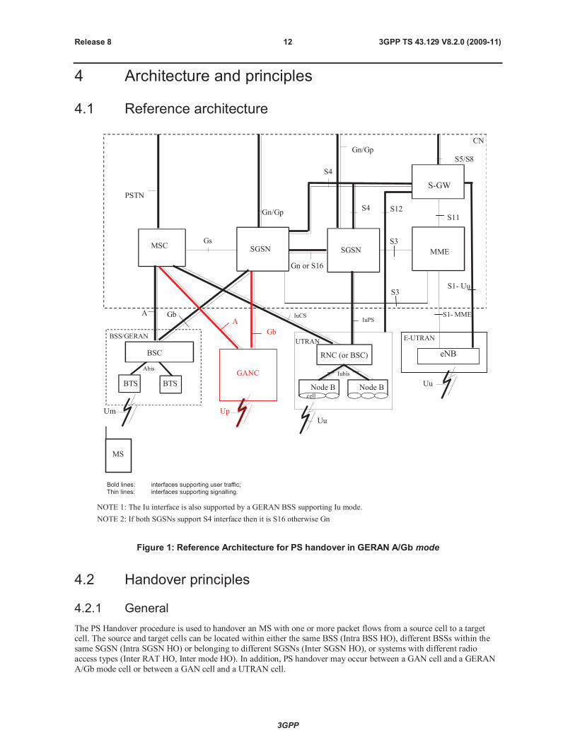
Bold lines: interfaces supporting user traffic;Thin lines: interfaces supporting signalling.
NOTE 1: The Iu interface is also supported by a GERAN BSS supporting Iu mode.
NOTE 2: If both SGSNs support S4 interface then it is S16 otherwise Gn
RNC (or BSC)
Node B Node B
Iubis
cell
Uu
SGSN
GANC
Up
A
Figure 1: Reference Architecture for PS handover in GERAN A/Gb mode
4.2 Handover principles
4.2.1 General
The PS Handover procedure is used to handover an MS with one or more packet flows from a source cell to a targetcell. The source and target cells can be located within either the same BSS (Intra BSS HO), different BSSs within the
same SGSN (Intra SGSN HO) or belonging to different SGSNs (Inter SGSN HO), or systems with different radio
access types (Inter RAT HO, Inter mode HO). In addition, PS handover may occur between a GAN cell and a GERAN
A/Gb mode cell or between a GAN cell and a UTRAN cell.
3GPP
3GPP TS 43.129 V8.2.0 (2009-11)13Release 8
While the MS is still in the source cell:
Radio resources in the target cell are allocated and signalled to the MS.
System information of the target cell needed for access in the target cell is signalled to the MS.
For each scenario (Intra BSS HO, Intra SGSN HO, Inter SGSN HO, Inter RAT HO/Inter mode HO) the PS handover
procedure is divided into:
a preparation phase; and
an execution phase.
By using the Gs interface (together with NMO1) the interruption time for the PS Handover procedure would be
shortened since using a combined LAU/RAU procedure would be possible.
The scenarios described in the remainder of sub-clause 4.2 are limited to the case where an MS is being served by a
BSS in GERAN A/Gb mode when a PS handover becomes necessary.
4.2.2 PS Handover preparation phase
The PS handover preparation phase consists of the following consecutive steps:
the decision by the source BSS to request a PS handover for an MS with one or more PFCs subject to handover:
- the request from the source BSS to the old SGSN for the PS handover;
- if the target BSS/GANC is not connected to the same SGSN the request from the old SGSN to the new SGSN
to reserve resources;
the reservation of resources in the target network nodes prior to ordering the MS to move to the target cell. This
involves:
- in case of Inter SGSN handover, the new SGSN reserving SNDCP/LLC resources and establishing Packet
Flow Contexts;
- in case of RA change the SGSN (which belongs to the RA) allocates a new P-TMSI and derives a new Local
TLLI from this P-TMSI;
- the target BSS/GANC reserving/allocating radio resources and Packet Flow Contexts in the target cell or the
target RNS reserving/allocating radio resources and RABs in the target cell;
- in case of Inter-SGSN handover, the definition of security related parameters for the new SGSN, e.g.
ciphering algorithm, to be used in the target cell immediately in both uplink and downlink directions.
When PS handover has to be performed for an MS with multiple active PFCs, the SGSN requests the target BSS/GANC
to create one or more PFCs or the target RNS to create one or more RABs corresponding to the active PFCs:
The target BSS/GANC may or may not establish radio resources for the created PFCs and the target RNS may
or may not allocate resources for all the requested RABs. If no radio resources at all are established the
handover shall be rejected (see Section 5.4.2).
If not all the PFCs can be created successfully the target BSS/GANC indicates this to the new SGSN, which
then informs the old SGSN/source BSS on the accepted and failed BSS PFCs.
If not all the RABs can be allocated the target RNS indicates this to the new SGSN, which then informs the old
SGSN/source BSS on the accepted and failed BSS PFCs.
PFCs for which no radio resources were reserved in the target BSS or for which no RABs were allocated in the
target RNS will result in the establishment of the necessary radio resources upon MS arrival in the target cell.
For the case of PS handover to GAN the target GANC shall either create all requested PFCs or none.
3GPP
3GPP TS 43.129 V8.2.0 (2009-11)14Release 8
4.2.3 PS Handover execution phase
The PS Handover execution phase consists of the following consecutive steps:
packet forwarding by the old SGSN of the received DL packets both to the source BSS, new SGSN (if the PS
handover involves a new SGSN) and the target BSS/GANC/RNS as soon as radio resources are reserved in the
target BSS/GANC/RNS;
the optional "blind" transmission by the target BSS/GANC of the DL RLC/MAC blocks/LLC PDUs over the
reserved radio resources in the target cell is only valid for lossy type of services where unacknowledged LLC
and RLC protocol modes are used;
the command generated by the target BSS/GANC/RNS sent via the source BSS to order the MS to handover to
the target cell;
the notification by the MS of its presence in the target cell on the allocated radio resources;
the redirection by the SGSN of the DL packets to the target BSS/GANC/RNS alone;
the release of the resources on the source side including PFCs and radio resources.
4.2.4 PS Handover Network Node Responsibilities
This clause would reflect the Agreed Handover principles from the clause A.1 by listing the specific noderesponsibilities during PS handover.
4.3 Protocol architecture
This clause will contain information on the services and functions provided and required by each layer.
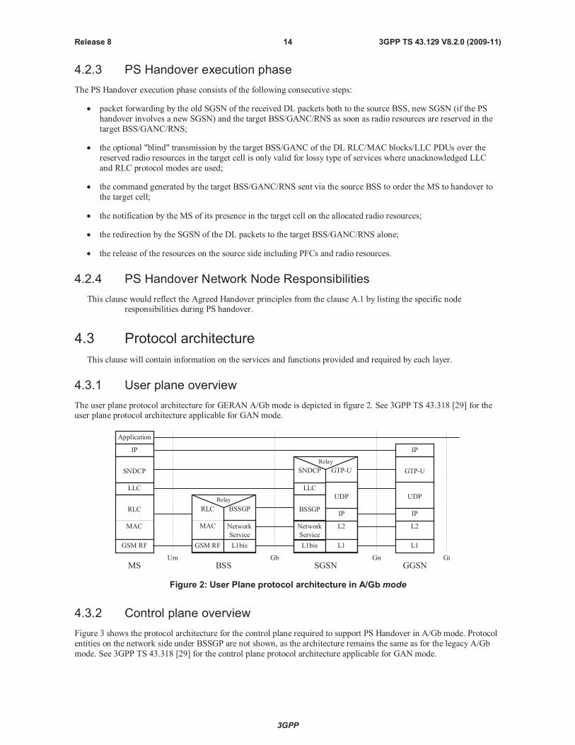
4.3.1 User plane overview
The user plane protocol architecture for GERAN A/Gb mode is depicted in figure 2. See 3GPP TS 43.318 [29] for theuser plane protocol architecture applicable for GAN mode.
Relay
Network
Service
GTP-U
Application
IP
SNDCP
LLC
RLC
MAC
GSM RF
SNDCP
LLC
BSSGP
L1bis
RLC
MAC
GSM RF
BSSGP
L1bis
Relay
L2
L1
IP
L2
L1
IP
GTP-U
IP
Um Gb Gn Gi
MS BSS SGSN GGSN
Network
Service
UDPUDP
Figure 2: User Plane protocol architecture in A/Gbmode
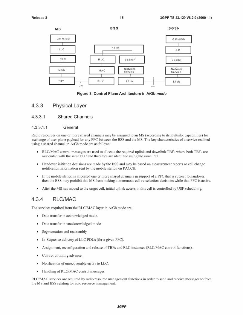
4.3.2 Control plane overview
Figure 3 shows the protocol architecture for the control plane required to support PS Handover in A/Gb mode. Protocol
entities on the network side under BSSGP are not shown, as the architecture remains the same as for the legacy A/Gb
mode. See 3GPP TS 43.318 [29] for the control plane protocol architecture applicable for GAN mode.
3GPP
3GPP TS 43.129 V8.2.0 (2009-11)15Release 8
BSSGP
Um
MS BSS
Re la y
SGSN
G b
LLC
GMM /SM
N etw o rkS erv ice
L1b is
BS SGP
N etw o rkS erv ic e
L1b is
LLC
GMM /SM
R LC
MAC
PH Y
RLC
PHY
MAC
Figure 3: Control Plane Architecture in A/Gb mode
4.3.3 Physical Layer
4.3.3.1 Shared Channels
4.3.3.1.1 General
Radio resources on one or more shared channels may be assigned to an MS (according to its multislot capabilities) for
exchange of user plane payload for any PFC between the BSS and the MS. The key characteristics of a service realized
using a shared channel in A/Gb mode are as follows:
RLC/MAC control messages are used to allocate the required uplink and downlink TBFs where both TBFs are
associated with the same PFC and therefore are identified using the same PFI.
Handover initiation decisions are made by the BSS and may be based on measurement reports or cell change
notification information sent by the mobile station on PACCH.
If the mobile station is allocated one or more shared channels in support of a PFC that is subject to handover,
then the BSS may prohibit this MS from making autonomous cell re-selection decisions while that PFC is active.
After the MS has moved to the target cell, initial uplink access in this cell is controlled by USF scheduling.
4.3.4 RLC/MAC
The services required from the RLC/MAC layer in A/Gb mode are:
Data transfer in acknowledged mode.
Data transfer in unacknowledged mode.
Segmentation and reassembly.
In-Sequence delivery of LLC PDUs (for a given PFC).
Assignment, reconfiguration and release of TBFs and RLC instances (RLC/MAC control functions).
Control of timing advance.
Notification of unrecoverable errors to LLC.
Handling of RLC/MAC control messages.
RLC/MAC services are required by radio resource management functions in order to send and receive messages to/fromthe MS and BSS relating to radio resource management.
3GPP
3GPP TS 43.129 V8.2.0 (2009-11)16Release 8
RLC/MAC supports the following radio resource management features that are required for PS handover:
Establishment of a TBF on one or more physical channel(s) in a given direction, for a given PFC.
Reconfiguration of the radio resources assigned to one or more TBFs in downlink and/or uplink within a cell.
Release of TBFs and associated radio resources following the corresponding service deactivation.
Release of all TBFs and associated radio resources in the source cell, as a result of handover to a target cell.
4.3.5 Radio Resource (RR)
This clause will contain information on any impacts on the RR protocol related to support of PS Handover.
4.3.6 BSSGP
BSSGP is expected to provide the signalling channel for PS Handover related signalling between the CN and the
BSS/GANC.
The services required from the BSSGP layer can therefore be summarised as:
Transmission and reception of PS Handover related messages (i.e. PFM messages) over the Gb interface.
Routing of PS Handover related messages to the PFM entity.
Handling of PS Handover related messages with the appropriate priority.
4.3.7 Overview of PS Handover Signalling Messages
The signalling messages used during PS handover are divided into four groups depending on the utilized interface:
PS handover signalling messages on the Um interface are RLC/MAC signalling blocks.
PS handover signalling messages on the Gb interface are BSSGP signalling messages sent by the PFM entity.
PS handover signalling messages on the Gn interface are GTP signalling messages.
PS handover signalling messages on the Up interface are GA-PSR signalling messages.
4.3.7.1 PS handover signalling messages on the Um interface
The signalling messages used on the Um interface are:
PS Handover Command (BSS -> MS).
Packet Control Acknowledgement (MS -> BSS).
PS Handover Access - Access Bursts (MS -> BSS).
Packet Physical Information (BSS->MS).
4.3.7.2 PS handover signalling messages on the Gb interface
The Gb interface signalling messages are new signalling messages carried by the BSSGP. These signalling messages
are to be defined in 3GPP TS 48.018 [10].
The signalling messages used on the Gb interface are:
PS Handover Required (BSS->CN):
- This message is sent from the BSS controlling the source cell to the SGSN to indicate that for a given MS
which already has radio resource(s) assigned, a PS handover is required.
3GPP
3GPP TS 43.129 V8.2.0 (2009-11)17Release 8
PS Handover Request (CN->BSS):
- This message is sent from the SGSN to the BSS controlling the target cell to request this BSS to reserve
resources for the MS subject to PS Handover.
PS Handover Request Acknowledge (BSS->CN):
- This message is sent from the BSS controlling the target cell to the SGSN to report the outcome of the
resource allocation for the requested BSS PFCs. This message indicates to the SGSN the successful resource
allocation and the failure for one or more requested BSS PFCs.
PS Handover Request Negative Acknowledge (BSS -> CN):
- This message is sent from the BSS controlling the target cell to the SGSN to report the failure of the resource
allocation for all the requested BSS PFCs.
PS Handover Complete (BSS->CN):
- This message is sent from the BSS controlling the target cell to the SGSN to notify the SGSN that the MShas made a successful access on the target cell. If the PS Handover to UTRAN and/or E-UTRAN is
supported by the MS and the BSS, it will also be used by the BSS to request the INTER RAT HANDOVER
INFO and/or E-UTRAN INTER RAT HANDOVER INFO from the SGSN.
PS Handover Complete Ack (CN->BSS):
- This message is sent from the SGSN to the BSS controlling the target cell to provide the MS inter-RAT
terminal capabilities (INTER RAT HANDOVER INFO and E-UTRAN INTER RAT HANDOVER INFO) if
those were requested by this BSS in the PS Handover Completemessage.
PS Handover Required Acknowledge (CN->BSS):
- This message is sent from the SGSN to the BSS controlling the source cell to indicate that the MS can switch
to the target cell.
PS Handover Cancel (BSS->CN):
- This message is sent from the BSS controlling the source cell to the SGSN to inform the SGSN to cancel an
ongoing handover.
PS Handover Required Negative Acknowledge (CN->BSS):
- This message is sent from the SGSN to the BSS controlling the source cell to inform unsuccessful resource
allocation or other PS handover failure in the target cell.
4.3.7.3 PS handover signalling messages on the Gn interface
The Gn interface signalling messages are existing messages that will be used as described in 3GPP TS 29.060 [11].
The signalling messages used on the Gn interface between source SGSN and target SGSN are:
Forward Relocation Request:
- The old SGSN shall send a Forward Relocation Request message to the new SGSN to convey necessary
information to perform the PS handover procedure between new SGSN and Target BSS.
Forward Relocation Response:
- The new SGSN shall send a Forward Relocation Response message to the old SGSN as a response to a
previous Forward Relocation Request message.
Forward Relocation Complete:
- The new SGSN shall send a Forward Relocation Complete message to the old SGSN to indicate that the PS
Handover procedure has been successfully finished.
3GPP
3GPP TS 43.129 V8.2.0 (2009-11)18Release 8
Forward Relocation Complete Acknowledge:
- The old SGSN sends a Forward Relocation Complete Acknowledge message to the new SGSN as a response
to Forward Relocation Complete message.
Relocation Cancel Request:
- The Relocation Cancel Request message is sent from the old SGSN to the new SGSN when the old SGSN is
requested to cancel the PS Handover procedure by the source BSS by means of BSSGP message.
Relocation Cancel Response:
- The Relocation Cancel Response message is sent from the new SGSN to the old SGSN when the PS
handover procedure has been cancelled in the old SGSN. This message is used as the response to the
Relocation Cancel Request message.
GTP messages need to be enhanced with additional IE to support PS Handover.
4.3.7.4 PS handover signalling messages on the Up interface
The signalling messages used on the Up interface (see 3GPP TS 44.318 [28]) are:
GA-PSR HANDOVER COMMAND message (GANC MS).
- This message is sent to trigger PS handover of an MS from a GAN cell to a GERAN A/Gb or UTRAN cell.
GA-PSR UPLINK QUALITY INDICATION (GANC MS)
- This message is sent to inform an MS of PS service related information as perceived by the GANC.
GA-PSR HANDOVER INFORMATION message (MS GANC)
- This message is sent by the MS to trigger the PS handover procedure in the GANC.
GA-PSR ACTIVATE UTC REQ message (GANC MS)
- This message is sent to allocate a GA-PSR Transport Channel to an MS.
GA-PSR ACTIVATE UTC ACK message (MS GANC)
- This message is sent to confirm the allocation of a GA-PSR Transport Channel to an MS.
GA-PSR HANDOVER COMPLETE (MS GANC)
- This message is sent to indicate the completion of PS handover to a GAN cell.
4.4 Identifiers
The identifiers used in PS handover for GERAN A/Gb mode are the identities used by the MS to connect via GERAN
through the Gb interface as well as through the Iu and S1 interface to the Core Network.
A large number of these identities for GERAN A/Gb mode will be utilized in the PS handover procedure in GERAN
A/Gb mode in the same manner as specified currently. However in order to support PS handover procedure new
identifiers will be defined as well.
In order to enable data transmission and to address the resources allocated by the target system during the PS Handover
procedure (i.e. for the case where the target cell belongs to another RA), before the MS moves to the target cell a new P-
TMSI will be allocated by the SGSN associated with the RA the target cell belongs to. The new P-TMSI is a temporary
and unique identifier in the new RA and is used to assign a local TLLI for the target cell.
NOTE: Further in this TS the term "local TLLI" refers to the Local TLLI derived from new P-TMSI assigned by
the new SGSN and utilized in the target cell, whereas the term "old TLLI" refers to the Local TLLI
utilized in the source cell that is derived from the P-TMSI assigned by the old SGSN.
3GPP
3GPP TS 43.129 V8.2.0 (2009-11)19Release 8
In case of inter RAT PS Handover to/from UTRAN and inter-mode handover to/from GERAN Iu mode, existing
UTRAN and GERAN Iu mode identifiers will be used.
In case of inter RAT PS Handover to/from E-UTRAN, identifiers defined for E-UTRAN will be used.
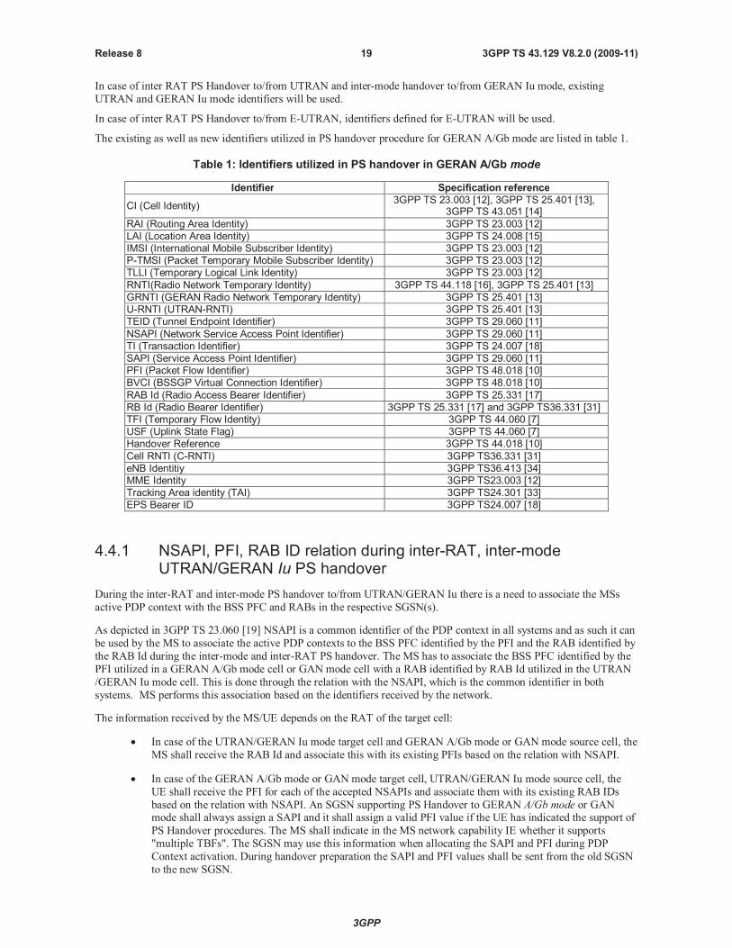
The existing as well as new identifiers utilized in PS handover procedure for GERAN A/Gb mode are listed in table 1.
Table 1: Identifiers utilized in PS handover in GERAN A/Gb mode
Identifier Specification reference
CI (Cell Identity)3GPP TS 23.003 [12], 3GPP TS 25.401 [13],
3GPP TS 43.051 [14]
RAI (Routing Area Identity) 3GPP TS 23.003 [12]
LAI (Location Area Identity) 3GPP TS 24.008 [15]
IMSI (International Mobile Subscriber Identity) 3GPP TS 23.003 [12]
P-TMSI (Packet Temporary Mobile Subscriber Identity) 3GPP TS 23.003 [12]
TLLI (Temporary Logical Link Identity) 3GPP TS 23.003 [12]
RNTI(Radio Network Temporary Identity) 3GPP TS 44.118 [16], 3GPP TS 25.401 [13]
GRNTI (GERAN Radio Network Temporary Identity) 3GPP TS 25.401 [13]
U-RNTI (UTRAN-RNTI) 3GPP TS 25.401 [13]
TEID (Tunnel Endpoint Identifier) 3GPP TS 29.060 [11]
NSAPI (Network Service Access Point Identifier) 3GPP TS 29.060 [11]
TI (Transaction Identifier) 3GPP TS 24.007 [18]
SAPI (Service Access Point Identifier) 3GPP TS 29.060 [11]
PFI (Packet Flow Identifier) 3GPP TS 48.018 [10]
BVCI (BSSGP Virtual Connection Identifier) 3GPP TS 48.018 [10]
RAB Id (Radio Access Bearer Identifier) 3GPP TS 25.331 [17]
RB Id (Radio Bearer Identifier) 3GPP TS 25.331 [17] and 3GPP TS36.331 [31]
TFI (Temporary Flow Identity) 3GPP TS 44.060 [7]
USF (Uplink State Flag) 3GPP TS 44.060 [7]
Handover Reference 3GPP TS 44.018 [10]
Cell RNTI (C-RNTI) 3GPP TS36.331 [31]
eNB Identitiy 3GPP TS36.413 [34]
MME Identity 3GPP TS23.003 [12]
Tracking Area identity (TAI) 3GPP TS24.301 [33]
EPS Bearer ID 3GPP TS24.007 [18]
4.4.1 NSAPI, PFI, RAB ID relation during inter-RAT, inter-modeUTRAN/GERAN Iu PS handover
During the inter-RAT and inter-mode PS handover to/from UTRAN/GERAN Iu there is a need to associate the MSs
active PDP context with the BSS PFC and RABs in the respective SGSN(s).
As depicted in 3GPP TS 23.060 [19] NSAPI is a common identifier of the PDP context in all systems and as such it can
be used by the MS to associate the active PDP contexts to the BSS PFC identified by the PFI and the RAB identified by
the RAB Id during the inter-mode and inter-RAT PS handover. The MS has to associate the BSS PFC identified by the
PFI utilized in a GERAN A/Gb mode cell or GAN mode cell with a RAB identified by RAB Id utilized in the UTRAN
/GERAN Iu mode cell. This is done through the relation with the NSAPI, which is the common identifier in both
systems. MS performs this association based on the identifiers received by the network.
The information received by the MS/UE depends on the RAT of the target cell:
In case of the UTRAN/GERAN Iu mode target cell and GERAN A/Gb mode or GAN mode source cell, the
MS shall receive the RAB Id and associate this with its existing PFIs based on the relation with NSAPI.
In case of the GERAN A/Gb mode or GAN mode target cell, UTRAN/GERAN Iu mode source cell, the
UE shall receive the PFI for each of the accepted NSAPIs and associate them with its existing RAB IDs
based on the relation with NSAPI. An SGSN supporting PS Handover to GERAN A/Gb mode or GANmode shall always assign a SAPI and it shall assign a valid PFI value if the UE has indicated the support of
PS Handover procedures. The MS shall indicate in the MS network capability IE whether it supports
"multiple TBFs". The SGSN may use this information when allocating the SAPI and PFI during PDP
Context activation. During handover preparation the SAPI and PFI values shall be sent from the old SGSN
to the new SGSN.
3GPP
3GPP TS 43.129 V8.2.0 (2009-11)20Release 8
If the old SGSN did not assign a valid PFI value for one or more PDP Contexts, the new SGSN shall after
successful completion of the RAU initiate explicit SM procedure to allocate a PFI value according to its
policy for each of the PDP Contexts for which no PFI is currently allocated. If none of the PDP Contexts
forwarded from the old SGSN has a valid PFI allocated the new SGSN shall consider this as a failure case
and the request for PS handover shall be rejected..
4.4.2 NSAPI, PFI, EPS Bearer ID relation during inter-RAT GERAN / E-UTRAN PS handover
General principles for mapping between PDP contexts and EPS bearers are described in 3GPP TS23.060; the mapping
of the QoS profiles is depicted in 3GPP TS 23.401. As specified in 3GPP TS 23.060 there is one to one mapping
between a PDP Context and EPS bearer, and their respective identifiers NSAPI and EPS bearer ID. In E-UTRAN aradio bearer (RB) transports the packets of an EPS bearer between a UE and an eNodeB. As defined in 3GPP TS23.401,
if a radio bearer exists, there is a one-to-one mapping between an EPS bearer and this radio bearer (RB).
The mobile station has to associate the BSS PFC identified by the PFI utilized in a GERAN A/Gb mode cell with a E-
UTRAN radio bearer identified by RB Id. This is done by the mobile station through the relation with the NSAPI and
EPS Bearer ID identifiers received by the network.
The MME supporting PS handover to/from GERAN performs similar functionality as the 3G SGSN such that it
allocates a PFI for each active EPS bearer initiated in E-UTRAN: The new SGSN in GERAN then acts as follows:
If for a given PDP Context the new SGSN does not receive a PFI from the MME then it will not proceed
with the PS handover for this flow i.e. it will not request the target BSS to allocate TBF resources
corresponding to that PDP Context.
If none of the PDP Contexts forwarded from the MME has a valid PFI allocated the new SGSN willconsider this as a failure case and the request for PS handover shall be rejected.
All PDP contexts for which no resources are allocated by the new SGSN or for which the new SGSN
cannot support the same SAPI and PFI (i.e. the corresponding NSAPIs are not addressed in the response
message of the target SGSN) will however be maintained and the related SAPIs and PFIs will be kept.
These PDP contexts may be modified or deactivated by the new SGSN via explicit SM procedures upon
RAU procedure.
5 Signalling procedures
5.1 GERAN (A/Gb mode) GERAN (A/Gb mode) handover
5.1.1 Intra Cell
Intra Cell PS Handover will be needed in cases when a new channel is selected in the same cell to be used by the MS.
This is handled by the BSS internally and if there are no changes in the new channel there is no need for BSS to notifythe SGSN about the change of channel.
BSS/SGSN signalling will be needed in case the new channel has limited resources and cannot support the same QoS,
for the BSS PFC as the old channel.
For these purpose existing modification procedures on the Um and Gb interface are used, e.g. PACKET TIMESLOT
RECONFIGURE (3GPP TS 44.060 [7]) on the air interface and MODIFY BSS PFC (3GPP TS 48.018 [10]) procedure
on the Gb interface.
If the modification procedures fail BSS may cancel the intra cell PS handover procedure.
3GPP
3GPP TS 43.129 V8.2.0 (2009-11)21Release 8
5.1.2 Intra BSS
5.1.2.1 General
This clause is further split into two clauses. The first describes an intra-BSS handover procedure based largely on theinter-BSS handover procedure. The second section describes an optional optimised intra-BSS handover procedure.
When the source and target cells are within the same BSS the handover can be either executed by the BSS itself
(optimised handover) or by involving the SGSN in the preparation phase. In the latter case although handover is
performed within one BSS the roles of source BSS and target BSS are the same as in Inter BSS Handover.
5.1.2.2 Intra BSS HO; Preparation phase
MS SGSNBSS
3. PS Handover Request
2. PS handover Required
5. PS Handover Request Acknowledge
1. Decision to performA/Gb PS Handover
4. BSS reserves radio resources and creates theTarget BSS to Source BSS Transparent Container
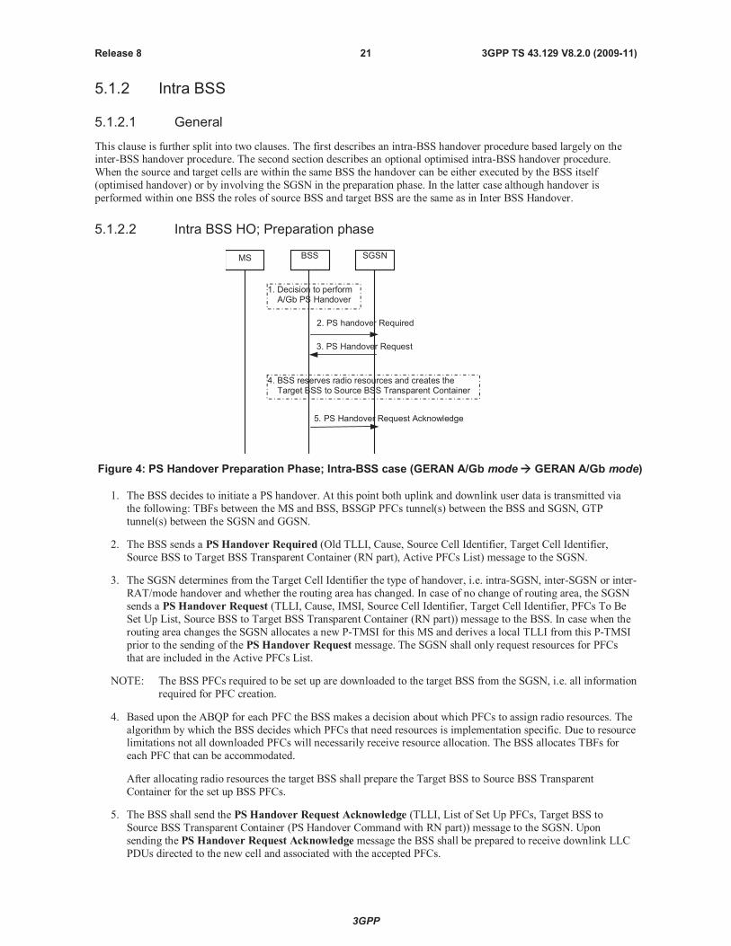
Figure 4: PS Handover Preparation Phase; Intra-BSS case (GERAN A/Gb mode GERAN A/Gb mode)
1. The BSS decides to initiate a PS handover. At this point both uplink and downlink user data is transmitted via
the following: TBFs between the MS and BSS, BSSGP PFCs tunnel(s) between the BSS and SGSN, GTP
tunnel(s) between the SGSN and GGSN.
2. The BSS sends a PS Handover Required (Old TLLI, Cause, Source Cell Identifier, Target Cell Identifier,
Source BSS to Target BSS Transparent Container (RN part), Active PFCs List) message to the SGSN.
3. The SGSN determines from the Target Cell Identifier the type of handover, i.e. intra-SGSN, inter-SGSN or inter-
RAT/mode handover and whether the routing area has changed. In case of no change of routing area, the SGSN
sends a PS Handover Request (TLLI, Cause, IMSI, Source Cell Identifier, Target Cell Identifier, PFCs To Be
Set Up List, Source BSS to Target BSS Transparent Container (RN part)) message to the BSS. In case when the
routing area changes the SGSN allocates a new P-TMSI for this MS and derives a local TLLI from this P-TMSI
prior to the sending of the PS Handover Request message. The SGSN shall only request resources for PFCs
that are included in the Active PFCs List.
NOTE: The BSS PFCs required to be set up are downloaded to the target BSS from the SGSN, i.e. all information
required for PFC creation.
4. Based upon the ABQP for each PFC the BSS makes a decision about which PFCs to assign radio resources. The
algorithm by which the BSS decides which PFCs that need resources is implementation specific. Due to resourcelimitations not all downloaded PFCs will necessarily receive resource allocation. The BSS allocates TBFs for
each PFC that can be accommodated.
After allocating radio resources the target BSS shall prepare the Target BSS to Source BSS Transparent
Container for the set up BSS PFCs.
5. The BSS shall send the PS Handover Request Acknowledge (TLLI, List of Set Up PFCs, Target BSS to
Source BSS Transparent Container (PS Handover Command with RN part)) message to the SGSN. Upon
sending the PS Handover Request Acknowledge message the BSS shall be prepared to receive downlink LLC
PDUs directed to the new cell and associated with the accepted PFCs.
3GPP
3GPP TS 43.129 V8.2.0 (2009-11)22Release 8
When the SGSN receives the PS Handover Request Acknowledgemessage and it decides to proceed with the
handover, the preparation phase is finished and the execution phase will follow.
5.1.2.3 Intra BSS HO; Execution phase
MS SGSNBSS GGSN
1. GTP Packets to SGSN
2. PS Handover Required Acknowledge
4. PS Handover Access
5. Packet Physical Information
7. PS Handover Complete
6. RA/Cell Update
3. PS Handover Command
Sending of uplink data possible
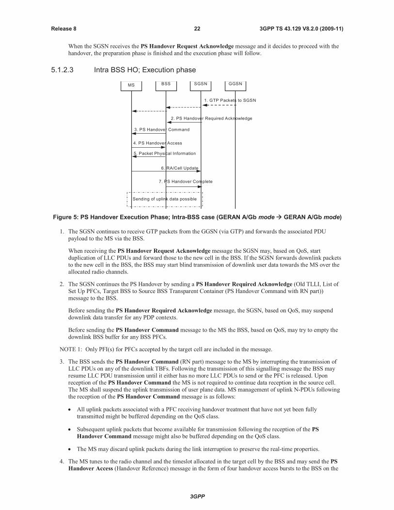
Figure 5: PS Handover Execution Phase; Intra-BSS case (GERAN A/Gb mode GERAN A/Gb mode)
1. The SGSN continues to receive GTP packets from the GGSN (via GTP) and forwards the associated PDU
payload to the MS via the BSS.
When receiving the PS Handover Request Acknowledgemessage the SGSN may, based on QoS, start
duplication of LLC PDUs and forward those to the new cell in the BSS. If the SGSN forwards downlink packets
to the new cell in the BSS, the BSS may start blind transmission of downlink user data towards the MS over the
allocated radio channels.
2. The SGSN continues the PS Handover by sending a PS Handover Required Acknowledge (Old TLLI, List of
Set Up PFCs, Target BSS to Source BSS Transparent Container (PS Handover Command with RN part))
message to the BSS.
Before sending the PS Handover Required Acknowledge message, the SGSN, based on QoS, may suspend
downlink data transfer for any PDP contexts.
Before sending the PS Handover Command message to the MS the BSS, based on QoS, may try to empty the
downlink BSS buffer for any BSS PFCs.
NOTE 1: Only PFI(s) for PFCs accepted by the target cell are included in the message.
3. The BSS sends the PS Handover Command (RN part) message to the MS by interrupting the transmission of
LLC PDUs on any of the downlink TBFs. Following the transmission of this signalling message the BSS may
resume LLC PDU transmission until it either has no more LLC PDUs to send or the PFC is released. Upon
reception of the PS Handover Command the MS is not required to continue data reception in the source cell.
The MS shall suspend the uplink transmission of user plane data. MS management of uplink N-PDUs following
the reception of the PS Handover Command message is as follows:
All uplink packets associated with a PFC receiving handover treatment that have not yet been fully
transmitted might be buffered depending on the QoS class.
Subsequent uplink packets that become available for transmission following the reception of the PS
Handover Command message might also be buffered depending on the QoS class.
The MS may discard uplink packets during the link interruption to preserve the real-time properties.
4. The MS tunes to the radio channel and the timeslot allocated in the target cell by the BSS and may send the PS
Handover Access (Handover Reference) message in the form of four handover access bursts to the BSS on the
3GPP
3GPP TS 43.129 V8.2.0 (2009-11)23Release 8
allocated channel. The PS Handover Command message indicates whether or not the MS shall send PS
Handover Accessmessages.
5. The BSS sends a Packet Physical information message to the MS containing update of the timing advance for
the MS to synchronize.
NOTE 2: In the case of pre-synchronised handover the MS may receive the timing advance information to use in
uplink in the target cell in the PS Handover Command message (if no timing advance information isincluded, the mobile station uses a default timing advance in the target cell). In a pre-synchronised or
synchronised handover, the Packet Physical information message is not sent in the target cell.
6. The MS sends uplink LLC PDUs, e.g. a Routing Area Update Request message or uplink user data packets to
the SGSN immediately after receiving the Packet Physical Information message or, in a synchronised or pre-
synchronised handover, immediately if the PS Handover Accessmessage is not required to be sent (see Section
6.2).
The MS shall resume the user data transfer only for those NSAPIs for which radio resources are allocated in the
target cell. For NSAPIs using LLC ADM for which radio resources were not allocated in the target cell the MS
may request radio resources using the legacy procedures.
7. Upon reception of the first correct RLC/MAC block (sent in normal burst format) from the MS the BSS sends a
PS Handover Complete (TLLI, IMSI) message to inform the SGSN that the MS has arrived in the target cell.
After the reception of the PS Handover Complete message the SGSN shall initiate the BSS PFC procedures to
delete the BSS PFC in the BSS controlling the source cell and shall be prepared to receive data from the new
cell. The source BSS initiates the release of the radio resources in the source cell after receiving the DELETE-
BSS-PFC PDU from the SGSN.
If Routing Area Update occurs after completion of the execution phase, then the CAMEL procedure calls shall be
performed according to 3GPP TS 23.060.
5.1.2.4 Intra BSS Handover - Optimised
This clause describes the optimised intra-BSS PS handover procedures applicable for the case where the source and
target cells are associated with the same Network Service Entity (NSE) and the same Routing Area (RA). The
optimisation involves the BSS providing the data forwarding function and does not require any explicit signalling with
the SGSN except the sending of PS Handover Complete at the end of PS Handover. Support for this procedure is
optional for the BSS.
Supporting this procedure requires that the BSS be able to determine whether or not it manages PS resources for thetarget cell, whether or not the target cell is associated with the same NSE, that it can internally forward LLC PDUs from
the source to the target cell and whether or not both cells are part of the same RA (i.e. the SGSN is not required to make
this determination and relay this information). If the BSS cannot make these determinations it shall use the non-
optimised intra-BSS PS handover procedures described in clauses 5.1.2.2 and 5.1.2.3.
3GPP
3GPP TS 43.129 V8.2.0 (2009-11)24Release 8
7. PS Handover Complete
MS BSS SGSN
2. BSS determines that it managestarget cell and that it is part of sameNSE and RA as the source cell
1. BSS decides to initiate A/Gb modePS handover
4. PS Handover Access
3. PS Handover Command
9. DL LLC PDU (new BVCI)
8. Packet Uplink Ack/Nack
5. Packet Physical Information
6. UL RLC/MAC dataandover Access
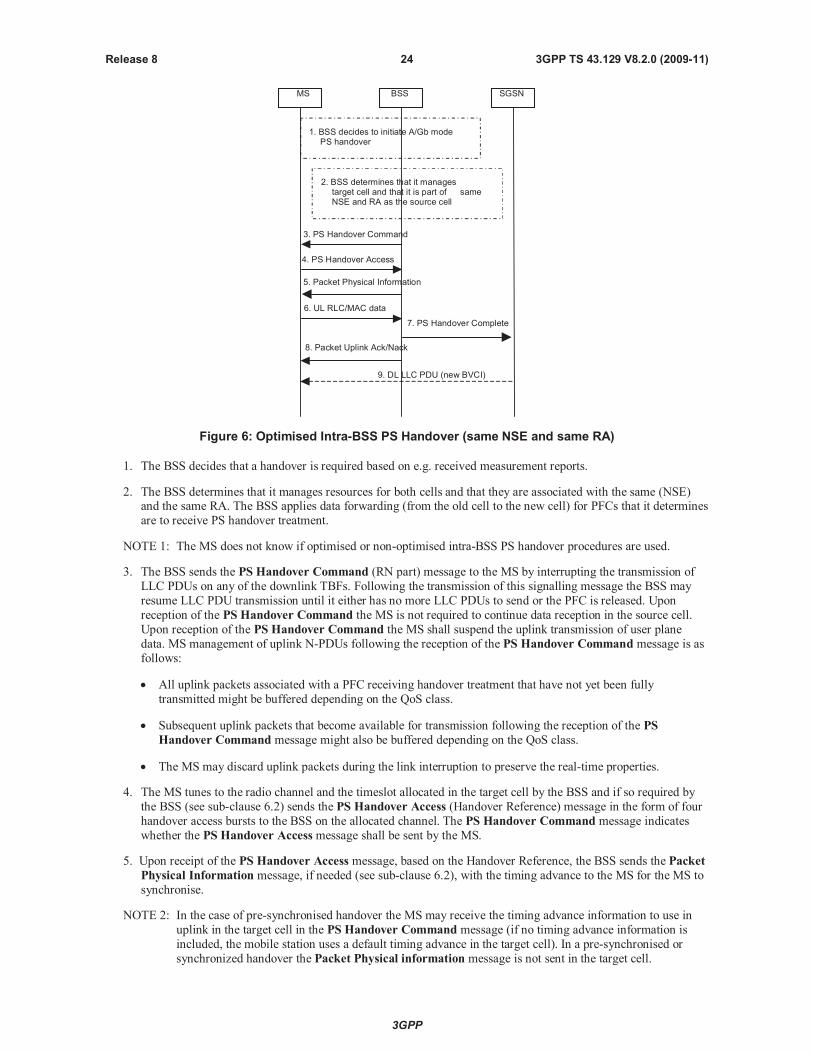
Figure 6: Optimised Intra-BSS PS Handover (same NSE and same RA)
1. The BSS decides that a handover is required based on e.g. received measurement reports.
2. The BSS determines that it manages resources for both cells and that they are associated with the same (NSE)and the same RA. The BSS applies data forwarding (from the old cell to the new cell) for PFCs that it determines
are to receive PS handover treatment.
NOTE 1: The MS does not know if optimised or non-optimised intra-BSS PS handover procedures are used.
3. The BSS sends the PS Handover Command (RN part) message to the MS by interrupting the transmission of
LLC PDUs on any of the downlink TBFs. Following the transmission of this signalling message the BSS may
resume LLC PDU transmission until it either has no more LLC PDUs to send or the PFC is released. Upon
reception of the PS Handover Command the MS is not required to continue data reception in the source cell.
Upon reception of the PS Handover Command the MS shall suspend the uplink transmission of user plane
data. MS management of uplink N-PDUs following the reception of the PS Handover Command message is as
follows:
All uplink packets associated with a PFC receiving handover treatment that have not yet been fully
transmitted might be buffered depending on the QoS class.
Subsequent uplink packets that become available for transmission following the reception of the PS
Handover Command message might also be buffered depending on the QoS class.
The MS may discard uplink packets during the link interruption to preserve the real-time properties.
4. The MS tunes to the radio channel and the timeslot allocated in the target cell by the BSS and if so required by
the BSS (see sub-clause 6.2) sends the PS Handover Access (Handover Reference) message in the form of four
handover access bursts to the BSS on the allocated channel. The PS Handover Command message indicates
whether the PS Handover Accessmessage shall be sent by the MS.
5. Upon receipt of the PS Handover Access message, based on the Handover Reference, the BSS sends the Packet
Physical Information message, if needed (see sub-clause 6.2), with the timing advance to the MS for the MS to
synchronise.
NOTE 2: In the case of pre-synchronised handover the MS may receive the timing advance information to use in
uplink in the target cell in the PS Handover Command message (if no timing advance information is
included, the mobile station uses a default timing advance in the target cell). In a pre-synchronised or
synchronized handover the Packet Physical information message is not sent in the target cell.
3GPP
3GPP TS 43.129 V8.2.0 (2009-11)25Release 8
6. The MS sends uplink LLC PDUs, e.g. uplink user data packets, in the allocated channel to the BSS.
The MS shall resume the user data transfer only for those NSAPIs for which there are radio resources allocated
in the target cell. For NSAPIs using LLC ADM for which radio resources were not allocated in the target cell the
MS may request radio resources using the legacy procedures.
7. Upon reception of the first correct RLC/MAC block (sent in normal burst format) from the MS, the BSS releases
the radio resources in the source cell and sends, on the target cell BVCI, the PS Handover Complete (TLLI,IMSI, Target Cell Identifier) message to the SGSN in order to indicate that the BSS has performed an internal
handover. In this case, the target cell is indicated in the PS Handover Complete message.
8. Once the BSS has correctly identified the MS, it sends a Packet Uplink Ack/Nack message (see 3GPP TS
44.060) indicating the status of the received RLC data blocks.
9. The reception of the PS Handover Complete message at the SGSN triggers the sending of downlink data to the
new cell using a new BVCI. The first DL PDU received by the BSS with the new-BVCI allows the BSS to clear
the relationship to the old BVCI.
The reception of the PS handover Complete message indicates to the SGSN that there is no need to wait for the Cell
Update sent from the MS to the SGSN.
NOTE 3: It is assumed here that downlink flow control is carried out on a per PFC basis and that the PFC specific
flow control parameters remain the same upon MS arrival in the target cell.
5.1.3 Intra SGSN
5.1.3.1 Intra SGSN/Inter BSS HO, Preparation phase
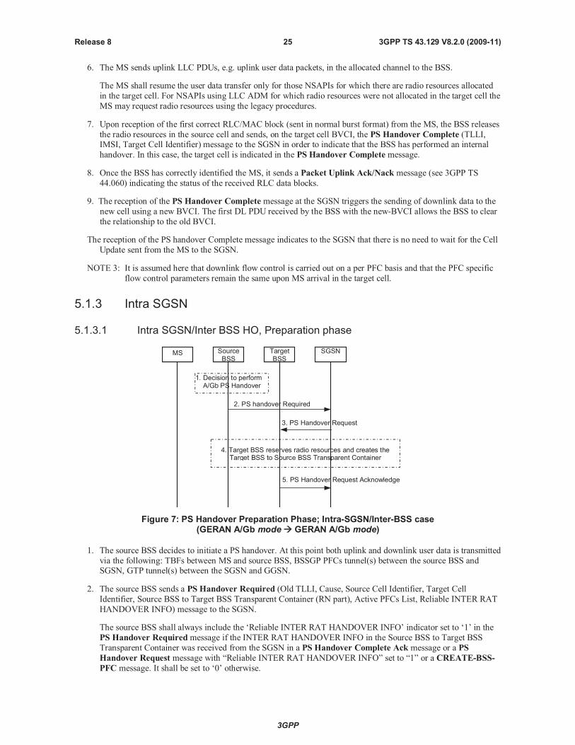
MS TargetBSS
SourceBSS
SGSN
3. PS Handover Request
2. PS handover Required
5. PS Handover Request Acknowledge
1. Decision to performA/Gb PS Handover
4. Target BSS reserves radio resources and creates theTarget BSS to Source BSS Transparent Container
Figure 7: PS Handover Preparation Phase; Intra-SGSN/Inter-BSS case(GERAN A/Gb mode GERAN A/Gb mode)
1. The source BSS decides to initiate a PS handover. At this point both uplink and downlink user data is transmitted
via the following: TBFs between MS and source BSS, BSSGP PFCs tunnel(s) between the source BSS andSGSN, GTP tunnel(s) between the SGSN and GGSN.
2. The source BSS sends a PS Handover Required (Old TLLI, Cause, Source Cell Identifier, Target Cell
Identifier, Source BSS to Target BSS Transparent Container (RN part), Active PFCs List, Reliable INTER RAT
HANDOVER INFO) message to the SGSN.
The source BSS shall always include the ‘Reliable INTER RAT HANDOVER INFO’ indicator set to ‘1’ in the
PS Handover Requiredmessage if the INTER RAT HANDOVER INFO in the Source BSS to Target BSS
Transparent Container was received from the SGSN in a PS Handover Complete Ack message or a PS
Handover Request message with “Reliable INTER RAT HANDOVER INFO” set to “1” or a CREATE-BSS-
PFC message. It shall be set to ‘0’ otherwise.
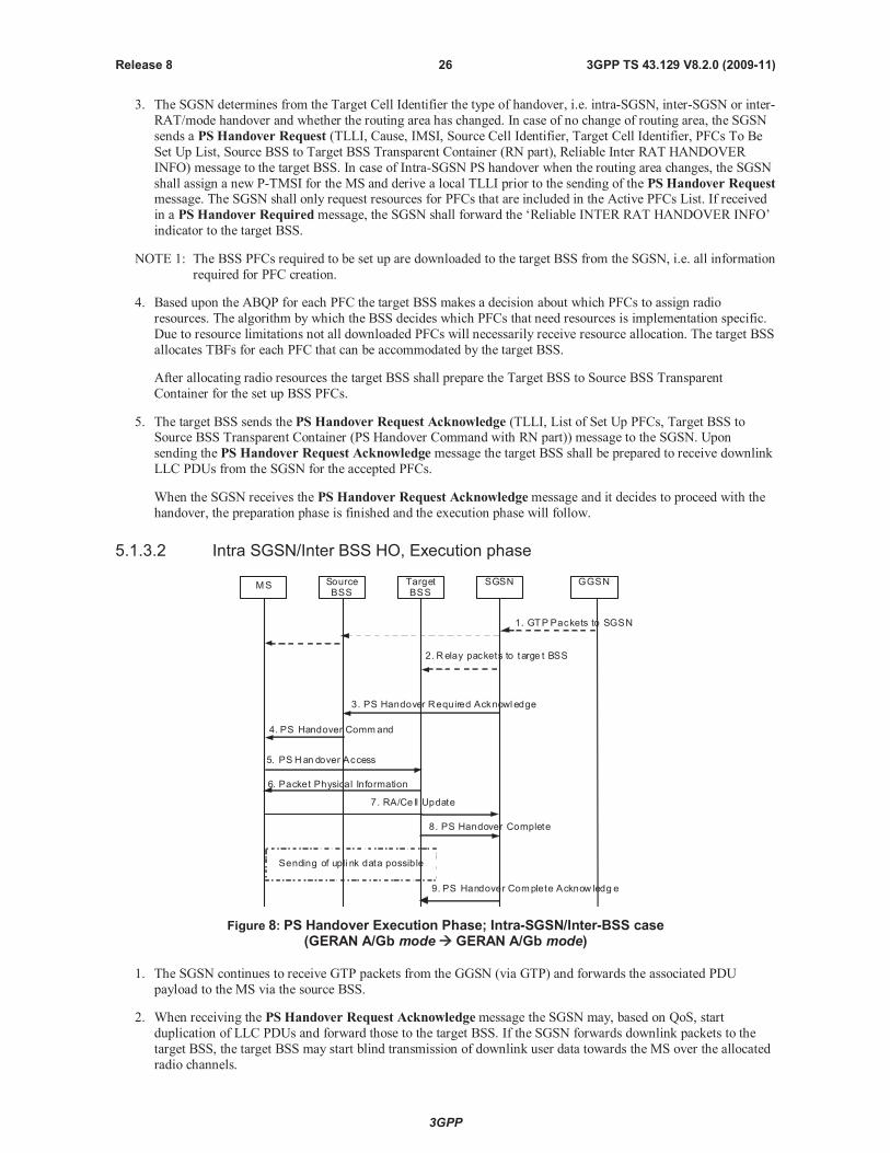
3GPP
3GPP TS 43.129 V8.2.0 (2009-11)26Release 8
3. The SGSN determines from the Target Cell Identifier the type of handover, i.e. intra-SGSN, inter-SGSN or inter-
RAT/mode handover and whether the routing area has changed. In case of no change of routing area, the SGSN
sends a PS Handover Request (TLLI, Cause, IMSI, Source Cell Identifier, Target Cell Identifier, PFCs To Be
Set Up List, Source BSS to Target BSS Transparent Container (RN part), Reliable Inter RAT HANDOVER
INFO) message to the target BSS. In case of Intra-SGSN PS handover when the routing area changes, the SGSN
shall assign a new P-TMSI for the MS and derive a local TLLI prior to the sending of the PS Handover Requestmessage. The SGSN shall only request resources for PFCs that are included in the Active PFCs List. If received
in a PS Handover Requiredmessage, the SGSN shall forward the ‘Reliable INTER RAT HANDOVER INFO’
indicator to the target BSS.
NOTE 1: The BSS PFCs required to be set up are downloaded to the target BSS from the SGSN, i.e. all information
required for PFC creation.
4. Based upon the ABQP for each PFC the target BSS makes a decision about which PFCs to assign radio
resources. The algorithm by which the BSS decides which PFCs that need resources is implementation specific.
Due to resource limitations not all downloaded PFCs will necessarily receive resource allocation. The target BSS
allocates TBFs for each PFC that can be accommodated by the target BSS.
After allocating radio resources the target BSS shall prepare the Target BSS to Source BSS Transparent
Container for the set up BSS PFCs.
5. The target BSS sends the PS Handover Request Acknowledge (TLLI, List of Set Up PFCs, Target BSS toSource BSS Transparent Container (PS Handover Command with RN part)) message to the SGSN. Upon
sending the PS Handover Request Acknowledge message the target BSS shall be prepared to receive downlink
LLC PDUs from the SGSN for the accepted PFCs.
When the SGSN receives the PS Handover Request Acknowledgemessage and it decides to proceed with the
handover, the preparation phase is finished and the execution phase will follow.
5.1.3.2 Intra SGSN/Inter BSS HO, Execution phase
MS TargetBSS
SourceBSS
SGSN GGSN
1. GTP Packets to SGSN
3. PS Handover Required Acknowl edge
5. PS Han dover Access
6. Packet Physical Information
8. PS Handover Complete
7. RA/Ce ll Update
4. PS Handover Command
2. Relay packets to targe t BSS
Sending of upli nk data possible
9. PS Handover Complete Acknow ledg e
Figure 8: PS Handover Execution Phase; Intra-SGSN/Inter-BSS case(GERAN A/Gb mode GERAN A/Gb mode)
1. The SGSN continues to receive GTP packets from the GGSN (via GTP) and forwards the associated PDU
payload to the MS via the source BSS.
2. When receiving the PS Handover Request Acknowledgemessage the SGSN may, based on QoS, start
duplication of LLC PDUs and forward those to the target BSS. If the SGSN forwards downlink packets to the
target BSS, the target BSS may start blind transmission of downlink user data towards the MS over the allocated
radio channels.
3GPP
3GPP TS 43.129 V8.2.0 (2009-11)27Release 8
3. The SGSN continues the PS Handover by sending a PS Handover Required Acknowledge (Old TLLI, List of
Set Up PFCs, Target BSS to Source BSS Transparent Container (PS Handover Command with RN part))
message to the source BSS.
Before sending the PS Handover Required Acknowledge message, the SGSN, based on QoS, may suspend
downlink data transfer for any PDP contexts.
Before sending the PS Handover Command message to the MS the source BSS, based on QoS, may try toempty the downlink BSS buffer for any BSS PFCs.
NOTE 1: Only PFI(s) for PFCs accepted by the target cell are included in the message.
4. The source BSS sends the PS Handover Command (RN part) message to the MS by interrupting the
transmission of LLC PDUs on any of the downlink TBFs. Following the transmission of this signalling message
the source BSS may resume LLC PDU transmission until it either has no more LLC PDUs to send or the PFC is
released. Upon reception of the PS Handover Command message the MS is not required to continue data
reception in the source cell. Upon reception of the PS Handover Command message the MS shall suspend the
uplink transmission of user plane data. MS management of uplink N-PDUs following the reception of the PS
Handover Command message is as follows:
All uplink packets associated with a PFC receiving handover treatment that have not yet been fully
transmitted might be buffered depending on the QoS class.
Subsequent uplink packets that become available for transmission following the reception of the PSHandover Command message might also be buffered depending on the QoS class.
The MS may discard uplink packets during the link interruption to preserve the real-time properties.
5. The MS tunes to the radio channel and the timeslot allocated in the target cell by the BSS and may send the PS
Handover Access (Handover Reference) message in the form of four handover access bursts to the BSS on the
allocated channel. The PS Handover Command message indicates whether or not the MS shall send PS
Handover Accessmessages.
6. The target BSS sends a Packet Physical information message to the MS containing the timing advance for the
MS to synchronise.
NOTE 2: In the case of pre-synchronised handover the MS may receive the timing advance information to use in
uplink in the target cell in the PS Handover Command message (if no timing advance information is
included, the mobile station uses a default timing advance in the target cell). In a pre-synchronised orsynchronized handover, the Packet Physical Information message is not sent in the target cell.
7. The MS sends uplink LLC PDUs, e.g. a Routing Area Update Request message or uplink user data packets to
the SGSN immediately after receiving the Packet Physical Information message or, in a synchronised or pre-
synchronised handover, immediately if the PS Handover Accessmessage is not required to be sent (see Section
6.2).
The MS shall resume the user data transfer only for those NSAPIs for which there are radio resources allocated
in the target cell. For NSAPIs using LLC ADM for which radio resources were not allocated in the target cell the
MS may request for radio resources using the legacy procedures.
8. Upon reception of the first correct RLC/MAC block (sent in normal burst format) from the MS the target BSS
sends a PS Handover Complete (TLLI, IMSI, Request for Inter RAT Handover Info) message to inform the
SGSN that the MS has arrived in the target cell. After the reception of the PS Handover Complete message the
SGSN shall initiate the BSS PFC procedures to delete the BSS PFC in the BSS controlling the source cell and
shall be prepared to receive data from the new cell. The source BSS initiates the release of the radio resources in
the source cell after receiving the DELETE-BSS-PFC PDU from the SGSN. The target BSS that supports inter-
RAT PS handover to UTRAN shall request the INTER RAT HANDOVER INFO from the SGSN if the
‘Reliable INTER RAT HANDOVER INFO’ is missing or set to ‘0’ in the PS Handover Request message or if
it has not received the INTER RAT HANDOVER INFO as part of the Source BSS to Target BSS transparentcontainer. The target BSS shall request the E-UTRAN INTER RAT HANDOVER INFO from the SGSN if it
supports inter-RAT PS handover to E-UTRAN and if it is missing the E-UTRAN INTER RAT HANDOVER
INFO.
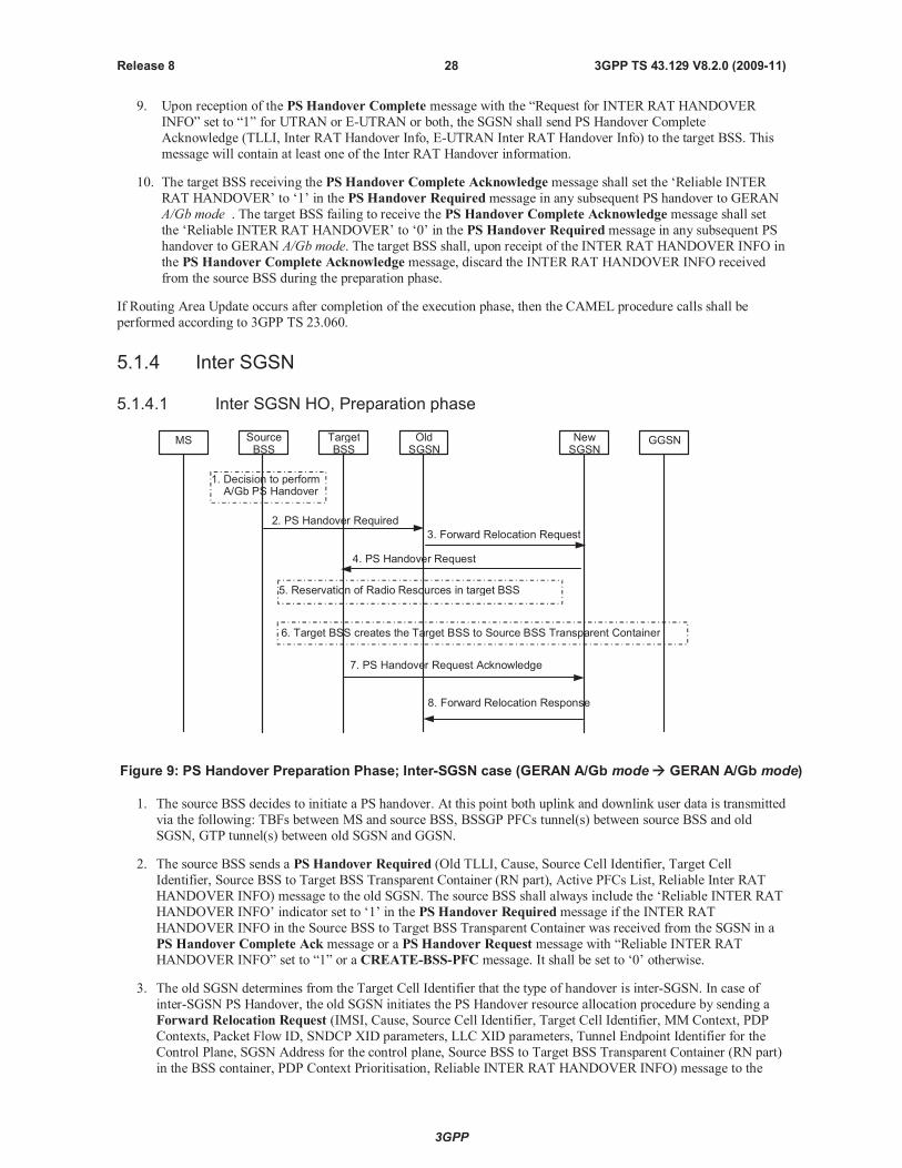
3GPP
3GPP TS 43.129 V8.2.0 (2009-11)28Release 8
9. Upon reception of the PS Handover Complete message with the “Request for INTER RAT HANDOVER
INFO” set to “1” for UTRAN or E-UTRAN or both, the SGSN shall send PS Handover Complete
Acknowledge (TLLI, Inter RAT Handover Info, E-UTRAN Inter RAT Handover Info) to the target BSS. This
message will contain at least one of the Inter RAT Handover information.
10. The target BSS receiving the PS Handover Complete Acknowledge message shall set the ‘Reliable INTER
RAT HANDOVER’ to ‘1’ in the PS Handover Requiredmessage in any subsequent PS handover to GERAN
A/Gb mode . The target BSS failing to receive the PS Handover Complete Acknowledge message shall set
the ‘Reliable INTER RAT HANDOVER’ to ‘0’ in the PS Handover Requiredmessage in any subsequent PS
handover to GERAN A/Gb mode. The target BSS shall, upon receipt of the INTER RAT HANDOVER INFO in
the PS Handover Complete Acknowledge message, discard the INTER RAT HANDOVER INFO received
from the source BSS during the preparation phase.
If Routing Area Update occurs after completion of the execution phase, then the CAMEL procedure calls shall be
performed according to 3GPP TS 23.060.
5.1.4 Inter SGSN
5.1.4.1 Inter SGSN HO, Preparation phase
MS TargetBSS
SourceBSS
OldSGSN
NewSGSN
GGSN
3. Forward Relocation Request
4. PS Handover Request
2. PS Handover Required
8. Forward Relocation Response
7. PS Handover Request Acknowledge
1. Decision to performA/Gb PS Handover
5. Reservation of Radio Resources in target BSS
6. Target BSS creates the Target BSS to Source BSS Transparent Container
Figure 9: PS Handover Preparation Phase; Inter-SGSN case (GERAN A/Gb mode GERAN A/Gb mode)
1. The source BSS decides to initiate a PS handover. At this point both uplink and downlink user data is transmitted
via the following: TBFs between MS and source BSS, BSSGP PFCs tunnel(s) between source BSS and old
SGSN, GTP tunnel(s) between old SGSN and GGSN.
2. The source BSS sends a PS Handover Required (Old TLLI, Cause, Source Cell Identifier, Target Cell
Identifier, Source BSS to Target BSS Transparent Container (RN part), Active PFCs List, Reliable Inter RAT
HANDOVER INFO) message to the old SGSN. The source BSS shall always include the ‘Reliable INTER RAT
HANDOVER INFO’ indicator set to ‘1’ in the PS Handover Requiredmessage if the INTER RAT
HANDOVER INFO in the Source BSS to Target BSS Transparent Container was received from the SGSN in a
PS Handover Complete Ack message or a PS Handover Request message with “Reliable INTER RAT
HANDOVER INFO” set to “1” or a CREATE-BSS-PFC message. It shall be set to ‘0’ otherwise.
3. The old SGSN determines from the Target Cell Identifier that the type of handover is inter-SGSN. In case of
inter-SGSN PS Handover, the old SGSN initiates the PS Handover resource allocation procedure by sending a
Forward Relocation Request (IMSI, Cause, Source Cell Identifier, Target Cell Identifier, MM Context, PDP
Contexts, Packet Flow ID, SNDCP XID parameters, LLC XID parameters, Tunnel Endpoint Identifier for the
Control Plane, SGSN Address for the control plane, Source BSS to Target BSS Transparent Container (RN part)
in the BSS container, PDP Context Prioritisation, Reliable INTER RAT HANDOVER INFO) message to the

3GPP
3GPP TS 43.129 V8.2.0 (2009-11)29Release 8
new SGSN. The old SGSN sends all active PDP contexts to the new SGSN indicating the PFIs and the XID
parameters related to those PDP contexts. Each PDP context contains the GGSN Address for the User Plane and
the Uplink TEID for Data (to this GGSN Address and Uplink TEID for Data the old SGSN and the new SGSN
send uplink packets).
The MM context contains security related information, e.g. used ciphering algorithm and ciphering key as
decribed in 3GPP TS 29.060 [11]. The relation between GSM and UMTS security parameters is defined in 3GPP
TS 33.102 [27].
The Ciphering key used by the old SGSN is reused by the new SGSN until a new authentication procedure is
performed (see clause 5.1.4.2, bullet 13).
If the new SGSN does not support the indicated ciphering algorithm, the new SGSN has to select a new
ciphering algorithm. This new algorithm will be sent transparently from the new SGSN to the MS. The IOV-UI
parameter generated in the new SGSN and used as input to the ciphering procedure will also be transferredtransparently from the new SGSN to the MS.
When the new SGSN receives the Forward Relocation Request message it extracts from the PDP Contexts the
associated NSAPIs, SAPIs and PFIs to be used in the new SGSN. In case when the new SGSN does not support
the same SAPI and PFI indicated by the old SGSN for a certain NSAPI, the new SGSN shall continue the PS
handover procedure only for those NSAPIs for which it can support the same PFI and SAPI as the old SGSN and
for which it can allocate resources. All PDP contexts for which no resources are allocated by the new SGSN orfor which it cannot support the same SAPI and PFI (i.e. the corresponding NSAPIs are not addressed in the
Forward Relocation Response message of the target SGSN), are maintained in the new SGSN and the related
SAPIs and PFIs are kept. When this occurs the packet data transfer corresponding to PDP Contexts for which
new SAPI and PFI values are needed are suspended. These PDP contexts may be modified or deactivated by the
new SGSN via explicit SM procedures upon the completion of the routing area update (RAU) procedure. When
the required PDP, MM, SNDCP and LLC contexts are established and the mapping between NSAPI, SAPI and
PFI for each of these PDP Contexts is established, the corresponding packet data transfer can continue.
If for a given PDP Context the new SGSN does not receive a PFI from the old SGSN, it shall not request the
target BSS to allocate TBF resources corresponding to that PDP Context.
If none of the PDP Contexts forwarded from the old SGSN has a valid PFI allocated the new SGSN shall
consider this as a failure case and the request for PS handover shall be rejected.
The old SGSN shall indicate the current XID parameter settings (i.e. those used at the old SGSN) to the new
SGSN. If the new SGSN can accept all XID parameters as indicated by the old SGSN, the new SGSN shall
create a NAS container for PS HO indicating 'Reset to the old XID parameters'.
NOTE 1: 'Reset to the old XID parameters' means that the LLC and SNDCP layer are reset, except for the LLC
XID parameters and SNDCP XID parameters which are re-initialized to the latest negotiated values,
and the negotiated compression entities which are re-initialized.
NOTE 2: void
Otherwise the new SGSN shall create a NAS container for PS HO indicating Reset (i.e. reset to default
parameters).
If received in a PS Handover Requiredmessage, the old SGSN shall forward the ‘Reliable INTER RAT
HANDOVER INFO’ indicator to the new SGSN in the Forward Relocation Request message.
4. The new SGSN sends a PS Handover Request (Local TLLI, Cause, IMSI, Source Cell Identifier, Target CellIdentifier, Source BSS to Target BSS Transparent Container (RN part), PFCs To Be Set Up List, NAS
container for PS HO, Reliable Inter RAT HANDOVER INFO) message to the target BSS. The new SGSN
shall not request resources for PFCs associated with PDP contexts with a maximum bit rate for uplink and
downlink of 0 kbit/s or for which the Activity Status Indicator within the PDP Context indicates that no
active PFC exists on the source side.
NOTE 3: The BSS PFCs required to be set up are downloaded to the target BSS from the new SGSN, i.e. all
information required for PFC creation.
5. Based upon the ABQP for each PFC the target BSS makes a decision about which PFCs to assign radio
resources. The algorithm by which the BSS decides which PFCs that need resources is implementation specific.

3GPP
3GPP TS 43.129 V8.2.0 (2009-11)30Release 8
Due to resource limitations not all downloaded PFCs will necessarily receive resource allocation. The target
BSS allocates TBFs for each PFC that can be accommodated by the target BSS.
6. The target BSS shall prepare the Target BSS to Source BSS Transparent Container which contains a PS
Handover Command including the CN part (NAS container for PS HO) and the RN part (PS Handover Radio
Resources).
7. The target BSS shall send the PS Handover Request Acknowledge (Local TLLI, List of Set Up PFCs, TargetBSS to Source BSS Transparent Container) message to the new SGSN. Upon sending the PS Handover
Request Acknowledge message the target BSS shall be prepared to receive downlink LLC PDUs from the new
SGSN for the accepted PFCs.
8. When the new SGSN receives the PS Handover Request Acknowledge message the Forward Relocation
Response (Cause, List of Set Up PFCs, Target BSS to Source BSS Transparent Container in the BSS
Container, Tunnel Endpoint Identifier Control Plane, SGSN Address for the control plane, Tunnel EndpointIdentifier Data II) message is sent from the new SGSN to the old SGSN. This message indicates that the new
SGSN is ready to receive packets forwarded from the old SGSN. If the target BSS or the new SGSN failed to
allocate resources this shall be indicated in the message. The Tunnel Endpoint Identifier Data II, one
information for each PDP context, contains the tunnel endpoint of the new SGSN and the IP address of the new
SGSN for data forwarding from the old to the new SGSN.
The new SGSN activates the allocated LLC/SNDCP engines as specified in 3GPP TS 44.064 [21] for an SGSNoriginated Reset or 'Reset to the old XID parameters'.
When the old SGSN receives the Forward Relocation Response message and it decides to proceed with the
handover, the preparation phase is finished and the execution phase will follow.
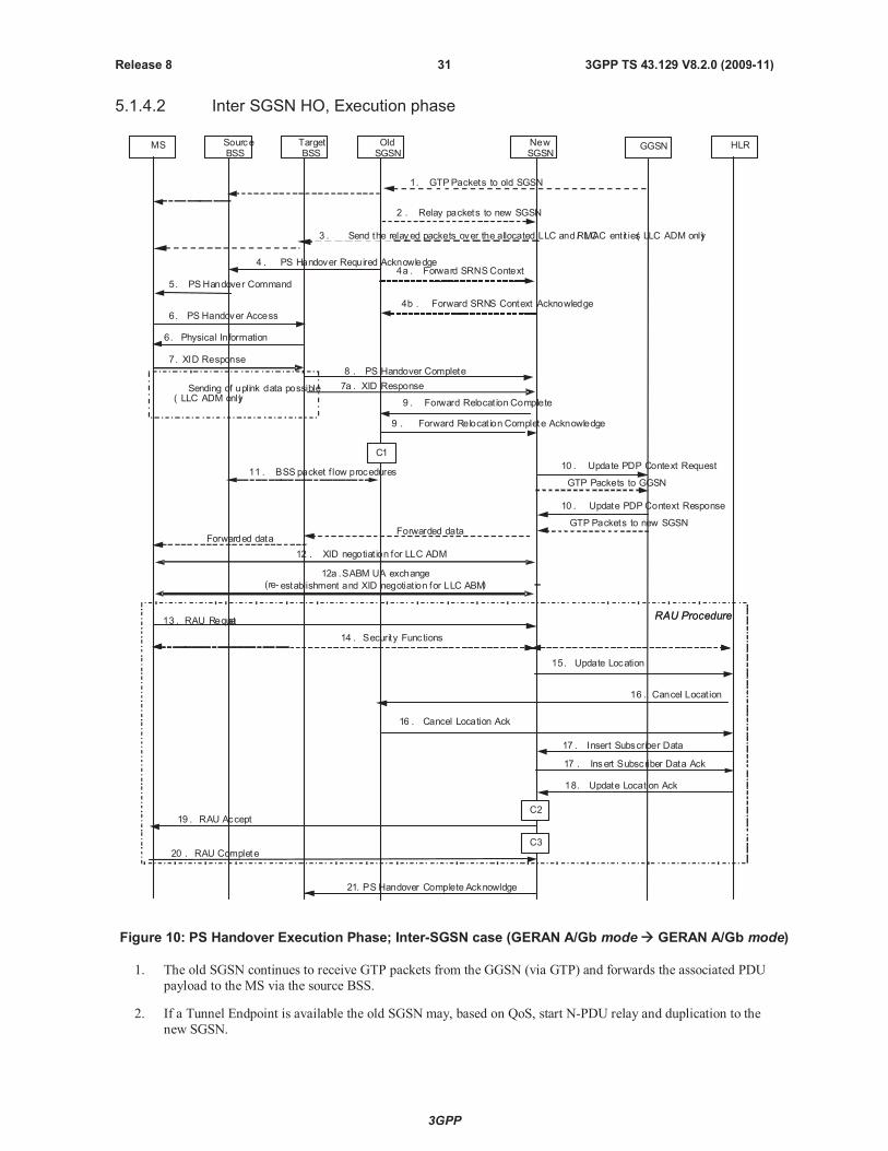
3GPP
3GPP TS 43.129 V8.2.0 (2009-11)31Release 8
5.1.4.2 Inter SGSN HO, Execution phase
MS TargetBSS
SourceBSS
OldSGSN
NewSGSN
GGSN
5. PSHandover Command
2 . Relay packets to new SGSN
3 . Send the relayed packets over the allocated LLC andRLC/ MAC entit ies( LLC ADM only)
1. GTPPackets to old SGSN
4 . PS Handover Required Acknowledge
10 . Update PDP Context Request
10 . Update PDP Context Response
6. PS Handover Access
HLR
GTP Packets to new SGSN
6. Physical Information
11 . BSS packet f low procedures
9 . Forward Relocat ion Complete
9 . Forward Relocat ion Complete Acknowledge
12 . XID negotiat ion for LLC ADM
8 . PS Handover Complete
17 . Insert Subscriber Data
17 . Insert Subscriber Data Ack
18. Update Location Ack
15. Update Location
14 . Security Functions
16 . Cancel Locat ion
16 . Cancel Location Ack
19 . RAU Accept
20 . RAU Complete
RAU Procedure
4a . Forward SRNSContext
4b . Forward SRNS Context Acknowledge
Sending of uplink data possible( LLC ADM only)
7. XID Response
12a .SABM UA exchange(re- establishment and XID negotiat ion for LLC ABM)
GTP Packets to GGSN
7a . XID Response
13 . RAU RequestRAU Procedure
Forwarded dataForwarded data
C1
C2
C3
21. PS Handover Complete Acknowldge
Figure 10: PS Handover Execution Phase; Inter-SGSN case (GERAN A/Gb mode GERAN A/Gb mode)
1. The old SGSN continues to receive GTP packets from the GGSN (via GTP) and forwards the associated PDU
payload to the MS via the source BSS.
2. If a Tunnel Endpoint is available the old SGSN may, based on QoS, start N-PDU relay and duplication to the
new SGSN.
3GPP
3GPP TS 43.129 V8.2.0 (2009-11)32Release 8
For PDP context which uses LLC ADM in the old SGSN all new downlink N-PDUs received after
completion of the PS handover preparation phase are relayed to the new SGSN. All such N-PDUs are
encapsulated in a GTP-PDU when transmitted to the new SGSN.
NOTE 1: The order of steps, starting from step 2 onwards, does not necessarily reflect the order of events. For
instance the old SGSN may start data forwarding (step 2), send the PS Handover Required
Acknowledge message (step 4) and send the Forward SRNS Context message (step 4a) almost
simultaneously.
3. The new SGSN may, based on QoS, proceed with the packet handling as follows:
For PDP context(s) which uses LLC ABM the new SGSN stores the N-PDUs associated with their number
into the SNDCP queue. Data transfer prior the exchange of N-PDU SNs is not possible.
For PDP context(s) which uses LLC ADM the new SGSN either
a. forwards the received downlink N-PDUs to the target BSS;
b. stores the received data into the SNDCP queue for e.g. the PDU lifetime;
c. discards the received data until e.g. reception of the PS Handover Complete message.
If the new SGSN forwards downlink packets to the target BSS, the target BSS may start a blind transmission of
downlink user data towards the MS over the allocated radio channels.
4. The old SGSN continues the PS Handover procedure by sending a PS Handover Required Acknowledge
(Old TLLI, PFCs Set Up List, Target BSS to Source BSS Transparent Container (PS Handover Command with
RN part and CN part)) message to the source BSS.
Before sending the PS Handover Required Acknowledge message, the old SGSN, based on QoS, may
suspend downlink data transfer for any PDP contexts.
Before sending the PS Handover Command message to the MS the source BSS, based on QoS, may try to
empty the downlink BSS buffer for any BSS PFCs.
NOTE 2: Only PFI(s) for PFCs accepted by the target cell are included in the message.
4a. The old SGSN shall send the Forward SRNS Context (NSAPI, DL GTP-U number, UL GTP-U number)
message to the new SGSN if there is at least one PDP context which requires "delivery order" to be preserved.
NSAPI identifies the PDP context to which the GTP-U numbers apply.
The Forward SRNS Context message is then acknowledged by the Forward SRNS Context Acknowledge
message. The Forward SRNS Context message contains the sequence numbers of the GTP-PDU next to be
transmitted in the uplink and downlink direction. After the Forward SRNS Context message is sent, further
uplink N-PDUs received by the old SGSN from the source BSS, relative to a PDP context which requires
"delivery order" to be preserved, shall not be forwarded to the GGSN.
The GTP-U sequence numbers are only sent by the old SGSN for PDP context(s) requiring delivery order
(QoS profile) to be preserved. If delivery order is to be preserved (QoS) profile), consecutive GTP-PDU
sequence numbering shall be maintained through the lifetime of the PDP context(s).
Therefore, during the entire PS Handover procedure for the PDP context(s) using delivery order required (QoS
profile), the responsible GTP-U entities (SGSNs and GGSN) shall assign consecutive GTP-PDU sequence
numbers to user packets belonging to the same PDP context uplink and downlink, respectively.
5. The source BSS sends the PS Handover Command (RN part, CN part) message to the MS by interrupting the
transmission of LLC PDUs on any of the downlink TBFs. The RN part and the CN part are transparentinformation to the BSS. Following the transmission of this signalling message the source BSS may resume
LLC PDU transmission until it either has no more LLC PDUs to send or the PFC is released. Upon reception
of the PS Handover Command message the MS is not required to continue data reception in the source cell.
Upon reception of the PS Handover Command message the MS shall suspend the uplink transmission of user
plane data. The MS management of uplink N-PDUs following the reception of the PS Handover Command
message is as follows:
3GPP
3GPP TS 43.129 V8.2.0 (2009-11)33Release 8
All uplink packets associated with a PFC receiving handover treatment that have not yet been fully
transmitted may be buffered depending on the QoS class. If the buffered uplink packets are transmitted in the
new cell, they need to be ciphered using the new IOV-UI after the handover.
Subsequent uplink packets that become available for transmission following the reception of the PS
Handover Command message might also be buffered depending on the QoS class.
The MS may discard uplink packets during the link interruption to preserve the real-time properties.
6. The MS tunes to the radio channel and the timeslot allocated in the target cell by the target BSS and may send
the PS Handover Access (Handover Reference) message in the form of four handover access bursts to the
target BSS on the allocated channel. The PS Handover Command message indicates whether or not the MS
shall send PS Handover Accessmessage. The target BSS sends a Packet Physical information message to
the MS containing the timing advance for the MS to synchronise.
NOTE 3: In the case of pre-synchronised handover the MS may receive the timing advance information to use in
uplink in the target cell in the PS Handover Command message (if no timing advance information is
included, the mobile station uses a default timing advance in the target cell). In a pre-synchronised or
synchronised handover the Packet Physical Information message is not sent in the target cell.
7./7a. After accessing the cell using access bursts and receiving timing advance information from the BSS in step 6,
the MS processes the NAS container and then sends one XID Response message to the new SGSN . The MS
sends this message immediately after receiving the Packet Physical Information message or, in a
synchronised or pre-synchronised handover, immediately if the PS Handover Accessmessage is not required
to be sent (see Section 6.2).
Upon sending the XID Response message the MS shall resume the user data transfer only for those NSAPIs for
which there are radio resources allocated in the target cell. For NSAPIs using LLC ADM for which radio
resources were not allocated in the target cell, the MS may request for radio resources using the legacy
procedures.
NOTE 4: If the new SGSN indicated Reset (i.e. reset to default parameters) in the NAS container for PS HO
included in the PS Handover Command, in order to avoid collision cases the mobile station may avoid
triggering XID negotiation for any LLC SAPI used in LLC ADM, but wait for the SGSN to do so (see
bullet 12). In any case the mobile station may avoid triggering XID negotiation for any LLC SAPI used in
LLC ABM, but wait for the SGSN to do so (see bullet 12a).
8. Upon reception of the first correct RLC/MAC block (sent in normal burst format) from the MS the target BSS
sends a PS Handover Complete (Local TLLI, IMSI, Request for Inter RAT Handover Info) message to
inform the new SGSN that the MS has arrived in the target cell. Each uplink N-PDU received by the new
SGSN via the target BSS is then forwarded directly to the GGSN. The target BSS that supports inter-RAT PS
handover to UTRAN shall request the INTER RAT HANDOVER INFO from the SGSN if the ‘Reliable
INTER RAT HANDOVER INFO’ is missing or set to ‘0’ in the PS Handover Request message or if it has
not received the INTER RAT HANDOVER INFO as part of the Source BSS to Target BSS transparent
container. The target BSS shall request the E-UTRAN INTER RAT HANDOVER INFO from the SGSN if it
supports inter-RAT PS handover to E-UTRAN and if it is missing the E-UTRAN INTER RAT.
9. Upon receiving the PS Handover Complete message, the new SGSN sends a Forward Relocation Complete
message to the old SGSN. The old SGSN responds with a Forward Relocation Complete Acknowledge
message. Upon the reception of the Forward Relocation Complete message the old SGSN starts a packet
forwarding timer. The old SGSN stops forwarding of data to the new SGSN after the packet forwarding timer
expires.
10. The new SGSN sends an Update PDP Context Request (New SGSN Address, TEID, QoS Negotiated)
message to the GGSN concerned. The GGSN updates the PDP context fields and returns an Update PDP
Context Response (TEID) message. From now on the GGSN sends new incoming downlink IP packets to the
new SGSN instead of to the old SGSN.
11. After the reception of the Forward Relocation Complete message the old SGSN deletes to BSS packet flow
context towards the old cell. The source BSS initiates the release of the radio resources in the source cell.
12. If the new SGSN indicated Reset (i.e. reset to default parameters) in the NAS container for PS HO included in
the PS Handover Command, then on receipt of the PS Handover Complete message the new SGSN initiates
an LLC/SNDCP XID negotiation for each LLC SAPI used in LLC ADM. In this case if the SGSN wants to use
3GPP
3GPP TS 43.129 V8.2.0 (2009-11)34Release 8
the default parameters, it shall send an empty XID Command. If the new SGSN indicated 'Reset to the old XID
parameters' in the NAS container for PS HO, no further XID negotiation is required for LLC SAPIs used in
LLC ADM only.
12a. The new SGSN re-establishes LLC ABM for the PDP contexts which use acknowledged information transfer.
During the exchange of SABM and UA the SGSN shall perform LLC/SNDCP XID negotiation.
13. The MS sends a Routing Area Update Request message to the new SGSN informing it that the target cellbelongs to a new routing area. The MS shall send this message immediately after message 7. The new SGSN
knows that a handover has been performed for this MS and can therefore exclude the SGSN context procedures
that normally are used within the RA Update procedure.
14. At this point the new SGSN may optionally invoke MS authentication (security function). The security
function can be deferred and performed at any later time as well.
NOTE 5: During an authentication procedure the SGSN has to suspend the downlink transmission of user data.
15. The new SGSN informs the HLR of the change of SGSN by sending Update Location (SGSN Number, SGSN
Address, IMSI) message to the HLR.
16. The HLR sends Cancel Location (IMSI, Cancellation Type) message to the old SGSN with Cancellation Type
set to Update Procedure. The old SGSN acknowledges with a Cancel Location Acknowledge (IMSI)
message. This message allows the old SGSN to know when to release the inter-SGSN tunnel.
17. The HLR sends Insert Subscriber Data (IMSI, GPRS subscription data) message to the new SGSN. The new
SGSN validates the MS presence in the (new) RA. If all checks are successful then the new SGSN constructs
an MM context for the MS and returns an Insert Subscriber Data Acknowledge (IMSI) message to the HLR.
This message allows the new SGSN to know when to release the inter-SGSN tunnel.
18. The HLR acknowledges the Update Location by sending an Update Location Acknowledge (IMSI) message
to the new SGSN.
19. The new SGSN validates the MS presence in the new RA. If the MS is allowed to be attached in this RA, the
SGSN updates the MM context for and sends a Routing Area Update Accept (P-TMSI, TMSI, P-TMSI
signature, Receive N-PDU number) message to the MS. The Receive N-PDU Number contains the
acknowledgements for each acknowledged-mode NSAPI used by the SGSN, thereby confirming all mobile-
originated N-PDUs successfully transferred before the start of the PS handover procedure.
20. The MS confirms the re-allocation of the new P-TMSI by responding the SGSN with a Routing Area UpdateComplete (Receive N-PDU number) message. The MS derives a new local TLLI from the new P-TMSI using
current MM procedures. The Receive N-PDU Number contains the acknowledgements for each
acknowledged-mode NSAPI used by the MS, thereby confirming all mobile-terminated N-PDUs successfully
transferred before the start of the handover procedure. If Receive N-PDU Number confirms reception of
N-PDUs that were forwarded from the old SGSN, these N-PDUs shall be discarded by the new SGSN.
The following CAMEL procedure calls shall be performed (see referenced procedures in TS 23.078 [8b])
C1) CAMEL_GPRS_PDP_Context_Disconnection, CAMEL_GPRS_Detach and CAMEL_PS_Notification.
They are called in the following order:
- The CAMEL_GPRS_PDP_Context_Disconnection procedure is called several times: once per PDP
context. The procedure returns as result "Continue".
- Then the CAMEL_GPRS_Detach procedure is called once. The procedure returns as result "Continue".
- Then the CAMEL_PS_Notification procedure is called once. The procedure returns as result "Continue".
C2) CAMEL_GPRS_Routeing_Area_Update_Session and CAMEL_PS_Notification.
They are called in the following order:
- The CAMEL_GPRS_Routeing_Area_Update_Session procedure is called. The procedure returns as
result "Continue".
- Then, the CAMEL_PS_Notification procedure is called. The procedure returns as result "Continue".

3GPP
3GPP TS 43.129 V8.2.0 (2009-11)35Release 8
C3) CAMEL_GPRS_Routeing_Area_Update_Context.
This procedure is called several times: once per PDP context. It returns as result "Continue".
For C2 and C3: refer to Routing Area Update procedure description in 3GPP TS 23.060.
21.Upon reception of the PS Handover Complete message with the “Request for Inter RAT Handover Info” set to
“1” for UTRAN or E-UTRAN or both, the SGSN shall send PS Handover Complete Acknowledge (TLLI,
Inter RAT Handover Info, E-UTRAN Inter RAT Handover Info) message to the target BSS. This message will
contain at least one of the Inter RAT Handover information.
22. The target BSS receiving the PS Handover Complete Acknowledge message shall set the ‘Reliable INTER
RAT HANDOVER’ to ‘1’ in the PS Handover Requiredmessage in any subsequent PS handover to GERAN
A/Gb mode. The target BSS failing to receive the PS Handover Complete Acknowledge message shall set the
‘Reliable INTER RAT HANDOVER’ to ‘0’ in the PS Handover Requiredmessage in any subsequent PS
handover to GERAN A/Gb mode. The Target BSS shall, upon receipt of the INTER RAT HANDOVER INFO
in the PS Handover Complete Acknowledge message, discard the INTER RAT HANDOVER INFO received
from the source BSS during the preparation phase.
5.2 Inter-RAT/mode handover (GERAN A/Gb mode UTRAN/GERAN Iu mode)
5.2.1 Intra SGSN
5.2.1.1 Intra-SGSN GERAN A/Gb mode to UTRAN/GERAN Iu mode HO;Preparation phase
2. PS Handover Required
4. Relocation Request Acknowledge
3. Relocation Request
1. Handover decision
MS SourceBSS
TargetRNC/BSS
3G/2GSGSN
Figure 11: PS Handover Preparation Phase; Inter-RAT/mode,Intra-SGSN case (GERAN A/Gb mode UTRAN, GERAN Iu mode)
1. The source BSS decides to initiate a PS handover. At this point both uplink and downlink user data is transmittedvia the following: TBFs between MS and source BSS, BSSGP PFCs tunnel(s) between the source BSS and
3G/2G SGSN, GTP tunnel(s) between the 3G/2G SGSN and GGSN.
2. The source BSS sends a PS Handover Required (TLLI, Cause, Source Cell Identifier, Target RNC Identifier,
Source to Target Transparent Container, Active PFCs List) message to the SGSN.
3. The 3G/2G SGSN determines from the Target RNC Identifier that the type of handover is inter-RAT/mode
handover. In case of Inter-RAT/Intra-SGSN PS handover, the 3G/2G SGSN constructs a Relocation Request
(Permanent NAS Identity, Cause, CN Domain Indicator, Integrity protection information (i.e. IK and allowed
Integrity Protection algorithms, Encryption information (i.e. CK and allowed Ciphering algorithms), RABs To
Be Set Up List, Source to Target Transparent Container, Iu Signalling connection identifier, Global CN-ID, SNA
Access Information, UESBI-Iu) message to the target RNC/BSS.
For each RAB requested to be established, the RABs To Be Set Up List shall contain information such as RAB
ID, RAB parameters, Transport Layer Address, and Iu Transport Association. The 3G/2G SGSN shall only
request resources for RABs for which the corresponding PFC is included in the Active PFCs List. The RAB ID
3GPP
3GPP TS 43.129 V8.2.0 (2009-11)36Release 8
information element contains the NSAPI value, and the RAB parameters information element gives the QoS
profile. The Transport Layer Address is the SGSN Address for user data, and the Iu Transport Association
corresponds to the uplink Tunnel Endpoint Identifier Data. The SGSN may decide to establish a Direct Tunnel.
In this case the SGSN provides to the target RNC the GGSN Address for User Plane and Uplink TEID for data.
Ciphering and integrity protection keys are sent to the target RNC/BSS to allow data transfer to continue in the
new RAT/mode target cell without requiring a new AKA (Authentication and Key Agreement) procedure.
Information that is required to be sent to the MS (either in the PS Handover Command message or after the
handover completion message) from RRC in the target RNC/BSS shall be included in the RRC message sent
from the target RNC/BSS to the MS via the transparent container.
In the target RNC/BSS radio and Iu user plane resources are reserved for the accepted RABs.
4. The target RNC/BSS sends the Relocation Request Acknowledge (Target to Source Transparent Container,
RABs setup list, RABs failed to setup list) message to the 3G/2G SGSN. Upon sending the Relocation RequestAcknowledge message the target RNC/BSS shall be prepared to receive downlink GTP PDUs from the 3G/2G
SGSN for the accepted RABs.
Each RAB to be setup is defined by a Transport Layer Address, which is the target RNC/BSS Address for user
data, and the Iu Transport Association, which corresponds to the downlink Tunnel Endpoint Identifier for user
data.
NOTE: The information to be included in the containers differs for UTRAN and GERAN Iu mode. For UTRAN,
the information included in the container is related to RAB setup and other IE similar to those in the
Handover to UTRAN message defined in 3GPP TS 25.331 [17]. For GERAN Iu mode the Radio
Bearer Reconfiguration message defined in 3GPP TS 44.118 [16] is the RRC message to be included.
When the 3G/2G SGSN receives the Relocation Request Acknowledge message and it decides to proceed with
the handover, the preparation phase is finished and the execution phase will follow.
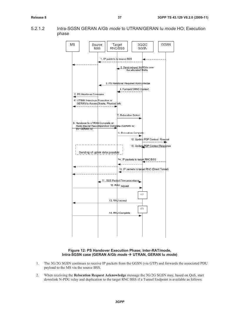
3GPP
3GPP TS 43.129 V8.2.0 (2009-11)37Release 8
5.2.1.2 Intra-SGSN GERAN A/Gb mode to UTRAN/GERAN Iu mode HO; Executionphase
Figure 12: PS Handover Execution Phase; Inter-RAT/mode,Intra-SGSN case (GERAN A/Gb mode UTRAN, GERAN Iu mode)
1. The 3G/2G SGSN continues to receive IP packets from the GGSN (via GTP) and forwards the associated PDU
payload to the MS via the source BSS.
2. When receiving the Relocation Request Acknowledge message the 3G/2G SGSN may, based on QoS, start
downlink N-PDU relay and duplication to the target RNC/BSS if a Tunnel Endpoint is available as follows:
3GPP
3GPP TS 43.129 V8.2.0 (2009-11)38Release 8
For PDP context, which uses LLC ADM, all new downlink N-PDUs received after completion of the PS
handover preparation phase are relayed to the target RNC. All such N-PDUs are encapsulated in a GTP-PDU
when transmitted to the target RNC/BSS.
If the 3G/2G SGSN forwards downlink packets to the target RNC/BSS, the target RNC/BSS may start blind
transmission of downlink user data towards the MS over the allocated radio channels.
3. The 3G/2G SGSN continues the PS Handover by sending a PS Handover Required Acknowledge (TLLI,List of Set Up PFCs, Target to Source Transparent Container) message to the source BSS.
Before sending the PS Handover Required Acknowledge message, the 3G/2G SGSN, based on QoS, may
suspend downlink data transfer for any PDP contexts.
Before sending the PS Handover Command message to the MS the source BSS, based on QoS, may try to
empty the downlink BSS buffer for any BSS PFCs.
4. The 3G/2G SGSN shall send the Forward SRNS Context (NSAPIDL GTP-U number, UL GTP-U number)message to the target RNC/BSS if there is at least one PDP context which requires "delivery order" to be
preserved..NSAPI identifies the PDP context to which the GTP-U numbers apply The Forward SRNS
Context message contains the sequence numbers of the GTP-PDU next to be transmitted in the uplink and
downlink direction. After the Forward SRNS Context message is sent, further uplink N-PDUs received by the
3G/2G SGSN from the source BSS, relative to a PDP context which requires "delivery order" to be preserved,
shall not be forwarded to the GGSN.
The GTP-U numbers are only sent by the 3G/2G SGSN for PDP context(s) requiring delivery order (QoS
profile) to be preserved. If delivery order is to be preserved (QoS) profile), consecutive GTP-PDU sequence
numbering shall be maintained through the lifetime of the PDP context(s).
Therefore, during the entire PS Handover procedure for the PDP context(s) using delivery order required (QoS
profile), the responsible GTP-U entities (3G/2G SGSN, target RNC/BSS and GGSN) shall assign consecutiveGTP-PDU sequence numbers to user packets belonging to the same PDP context uplink and downlink,
respectively.
The target RNC/BSS proceed as follows:
For RABs not requiring lossless PDCP the target RNC/BSS may, according the QoS profile of the PDP
context, store the received data until it receives confirmation of MS presence in the target cell.
The further target RNC/BSS behaviour is as specified in 3GPP TS 23.060 [19] (Combined Hard Handoverand SRNS Relocation).
5. The source BSS sends the PS Handover Command message containing theHandover to UTRAN
Command message (as it is specified in 3GPP TS 25.331 [17]) or Radio Bearer Reconfiguration message
(as it is specified in 3GPP TS 44.118 [16]) to the MS by interrupting the transmission of LLC PDUs on any of
the downlink TBFs. Following the transmission of this signalling message the source BSS may resume LLC
PDU transmission until it either has no more LLC PDUs to send or the PFC is released. Upon reception of thePS Handover Command the MS is not required to continue data reception in the source cell. Upon reception
of the PS Handover Command the MS shall suspend the uplink transmission of user plane data. MS
management of uplink N-PDUs following the reception of the PS Handover Command message is as
follows:
All N-PDUs associated with a PFC receiving handover treatment that have not yet been fully transmittedmight be buffered depending on the QoS class.
Subsequent uplink N-PDUs that become available for transmission following the reception of the PS
Handover Command message might also be buffered depending on the QoS class.
For real time services uplink N-PDUs may be discarded by the MS during the link interruption.
NOTE: Any buffering should be performed before the data is passed to SNDCP in order to avoid header
compression on N-PDUs such that data delivery in the target cell may begin from the correct point in thesequence.
6. MS is in the target cell and performs access to UTRAN as defined in 3GPP TS 25.331 [17] and to GERAN Iu
mode as defined in 3GPP TS 44.118 [16].
3GPP
3GPP TS 43.129 V8.2.0 (2009-11)39Release 8
7. The target RNC/BSS sends a Relocation Detectmessage to the 3G/2G SGSN to indicate that the MS is in the
target cell. The message shall be sent when the relocation execution trigger is received. For SRNS relocation
type "UE Involved", the relocation execution trigger may be received from the Uu interface; i.e. when the
target RNC detects the MS on the lower layers. When the Relocation Detect message is sent, the target RNC
shall start serving RNC operation.
8. In UTRAN, the MS sendsHandover to UTRAN Complete {Message Type, UE Information elements (Start
List, CN Domain Identity, Start), RB Information Elements (Count-C Activation Time)} message to the target
RNC (see 3GPP TS 25.331 [17]).
In GERAN Iu, the MS sends Radio Bearer Reconfiguration Complete {RRC Transaction Identifier,
Integrity Check Info, Uplink Integrity Protection Activation Info, COUNT-C Activation Time, Radio Bearer
Uplink Ciphering Activation Time Info, Mobile Observed Time Difference, Uplink Counter Synchronisation
Info struct, START List, CN Domain Identity, START, RB with PDCP Information List, RB with PDCP
Information} message to target BSS.
9. When the new source RNC-ID + S-RNTI are successfully exchanged with the MS, the target RNC/BSS shall
send the Relocation Complete message to the new SGSN. The purpose of the Relocation Complete procedure
is to indicate by the target RNC/BSS the completion of the relocation of the source BSS to the CN. After the
reception of the Relocation Complete message the 3G/2G SGSN shall be prepared to receive data from the
target RNC/BSS.
10. If the SGSN has established Direct Tunnel, the SGSN sends an Update PDP Context Request (RNC Address,
TEID, QoS Negotiated, DTI) message to the GGSN concerned. The SGSN provides to the GGSN the RNC
address for the User Plane and TEID for downlink data and shall include the DTI to instruct the GGSN to
apply Direct Tunnel specific error handling procedure as defined in 3GPP TS 23.060 [19]. The GGSN updates
the PDP context fields and returns an Update PDP Context Response (TEID) message. From now on the
GGSN sends new incoming downlink IP packets to the target RNC instead of the SGSN.
11. The 3G/2G SGSN shall initiate PFC Management procedures towards the source cell in order to trigger the
release of resources in the source cell.
12. The MS sends a Routing Area Update Request (Old RAI, Old P-TMSI signature, Update Type) message to
the 3G/2G SGSN. This is done even if the target cell belongs to the same routing area as the source cell. The
MS shall send this message immediately after message 8. The 3G/2G SGSN knows that a handover has beenperformed for this MS and can therefore exclude the SGSN context procedures which normally are used within
the RA Update procedure.
13. The 3G/2G SGSN validates the MS presence in the new RA. If the MS is allowed to be attached in this RA, the
3G/2G SGSN updates the MM context for and sends a Routing Area Update Accept message to the MS.
14. The MS may respond to the SGSN with a Routing Area Update Complete message.
The following CAMEL procedure calls shall be performed (see referenced procedures in TS 23.078 [8b]):
C2) CAMEL_GPRS_Routeing_Area_Update_Session and CAMEL_PS_Notification.
They are called in the following order:
- The CAMEL_GPRS_Routeing_Area_Update_Session procedure is called. The procedure returns as
result "Continue".
- Then, the CAMEL_PS_Notification procedure is called. The procedure returns as result "Continue".
C3) CAMEL_GPRS_Routeing_Area_Update_Context.
This procedure is called several times: once per PDP context. It returns as result "Continue".
For C2 and C3: refer to Routing Area Update procedure description in 3GPP TS 23.060.
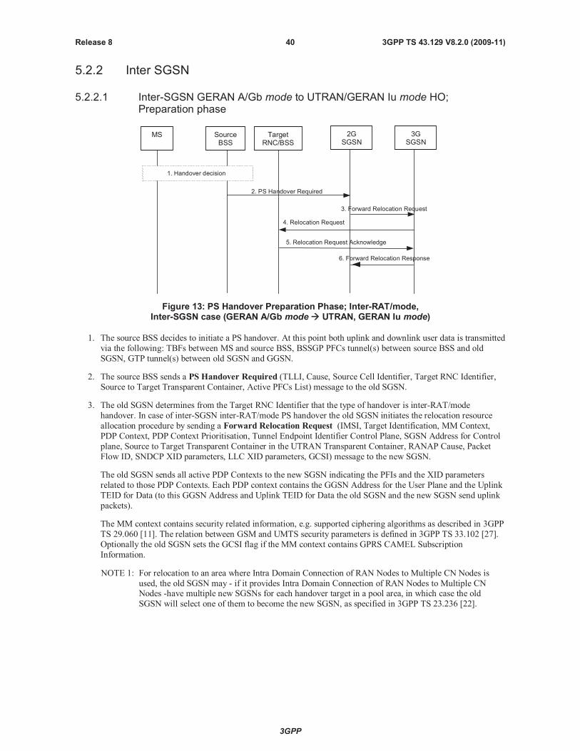
3GPP
3GPP TS 43.129 V8.2.0 (2009-11)40Release 8
5.2.2 Inter SGSN
5.2.2.1 Inter-SGSN GERAN A/Gb mode to UTRAN/GERAN Iu mode HO;Preparation phase
2. PS Handover Required
5. Relocation Request Acknowledge
3. Forward Relocation Request
4. Relocation Request
6. Forward Relocation Response
1. Handover decision
MS SourceBSS
TargetRNC/BSS
2GSGSN
3GSGSN
Figure 13: PS Handover Preparation Phase; Inter-RAT/mode,Inter-SGSN case (GERAN A/Gb mode UTRAN, GERAN Iu mode)
1. The source BSS decides to initiate a PS handover. At this point both uplink and downlink user data is transmitted
via the following: TBFs between MS and source BSS, BSSGP PFCs tunnel(s) between source BSS and old
SGSN, GTP tunnel(s) between old SGSN and GGSN.
2. The source BSS sends a PS Handover Required (TLLI, Cause, Source Cell Identifier, Target RNC Identifier,
Source to Target Transparent Container, Active PFCs List) message to the old SGSN.
3. The old SGSN determines from the Target RNC Identifier that the type of handover is inter-RAT/mode
handover. In case of inter-SGSN inter-RAT/mode PS handover the old SGSN initiates the relocation resource
allocation procedure by sending a Forward Relocation Request (IMSI, Target Identification, MM Context,
PDP Context, PDP Context Prioritisation, Tunnel Endpoint Identifier Control Plane, SGSN Address for Control
plane, Source to Target Transparent Container in the UTRAN Transparent Container, RANAP Cause, Packet
Flow ID, SNDCP XID parameters, LLC XID parameters, GCSI) message to the new SGSN.
The old SGSN sends all active PDP Contexts to the new SGSN indicating the PFIs and the XID parameters
related to those PDP Contexts. Each PDP context contains the GGSN Address for the User Plane and the Uplink
TEID for Data (to this GGSN Address and Uplink TEID for Data the old SGSN and the new SGSN send uplink
packets).
The MM context contains security related information, e.g. supported ciphering algorithms as described in 3GPP
TS 29.060 [11]. The relation between GSM and UMTS security parameters is defined in 3GPP TS 33.102 [27].
Optionally the old SGSN sets the GCSI flag if the MM context contains GPRS CAMEL Subscription
Information.
NOTE 1: For relocation to an area where Intra Domain Connection of RAN Nodes to Multiple CN Nodes is
used, the old SGSN may - if it provides Intra Domain Connection of RAN Nodes to Multiple CNNodes -have multiple new SGSNs for each handover target in a pool area, in which case the old
SGSN will select one of them to become the new SGSN, as specified in 3GPP TS 23.236 [22].
3GPP
3GPP TS 43.129 V8.2.0 (2009-11)41Release 8
Upon receipt of the message, the new SGSN establishes all MM and PDP contexts and initiates the RAB setup
procedures for all PDP contexts received.
4. The new SGSN sends a Relocation Request (Permanent NAS Identity, Cause, CN Domain Indicator, Integrity
protection information (i.e. IK and allowed Integrity Protection algorithms), Encryption information (i.e. CK and
allowed Ciphering algorithms), RABs to be setup list, Source to Target Transparent Container, Iu Signalling
connection identifier, Global CN-ID, SNA Access Information, UESBI-Iu) message to the target RNC/BSS.
For each RAB requested to be established, RABs To Be Setup shall contain information such as RAB ID, RAB
parameters, Transport Layer Address, and Iu Transport Association. The new SGSN shall not request resources
for RABs associated with PDP contexts with a maximum bit rate for uplink and downlink of 0 kbit/s or for
which the Activity Status Indicator within the PDP Context indicates that no active PFC exists on the source
side. The RAB ID information element contains the NSAPI value, and the RAB parameters information element
gives the QoS profile. The Transport Layer Address is the SGSN Address for user data, and the Iu Transport
Association corresponds to the uplink Tunnel Endpoint Identifier Data. The SGSN may decide to establish a
Direct Tunnel unless it has received a ‘set’ GCSI flag from the old SGSN. If the new SGSN decides to establish
Direct Tunnel, it provides to the target RNC the GGSN Address for User Plane and TEID for Uplink data.
Ciphering and integrity protection keys are sent to the target RNC/BSS to allow data transfer to continue in the
new RAT/mode target cell without requiring a new AKA (Authentication and Key Agreement) procedure.
Information that is required to be sent to the MS (either in the PS Handover Command message or after the
handover completion message) from RRC in the target RNC/BSS shall be included in the RRC message sent
from the target RNC/BSS to the MS via the transparent container.
In the target RNC/BSS radio and Iu user plane resources are reserved for the accepted RABs.
5. The target RNC/BSS sends the Relocation Request Acknowledge (Source to Target Transparent Container,
RABs setup list, RABS failed to setup list) message to the new SGSN. Upon sending the Relocation RequestAcknowledge message the target RNC/BSS shall be prepared to receive downlink GTP PDUs from the new
SGSN for the accepted RABs.
Each RAB to be setup is defined by a Transport Layer Address, which is the target RNC/BSS Address for user data, and
the Iu Transport Association, which corresponds to the downlink Tunnel Endpoint Identifier for user data.
NOTE 2: The information to be included in the containers differs for UTRAN and GERAN Iu mode. For UTRAN,
the information included in the container is related to RAB setup and other IE similar to those in the
Handover to UTRAN message defined in 3GPP TS 25.331 [17]. For GERAN Iu mode the Radio
Bearer Reconfiguration message defined in 3GPP TS 44.118 [16] is the RRC message to be included.
6. When resources for the transmission of user data between target RNC/BSS and new SGSN have been allocated
and the new SGSN is ready for the PS handover, the Forward Relocation Response (Cause, List of Set Up
PFCs, Tunnel Endpoint Identifier Control Plane, SGSN Address for User Traffic, Tunnel Endpoint Identifier
Data II, RANAP cause, SGSN Address for control plane, Source to Target Transparent Container in the UTRAN
Transparent Container) message is sent from the new SGSN to the old SGSN. RAN Transparent Container and
RANAP Cause contain information from the target RNC/BSS to be forwarded to the source BSS.
The Tunnel Endpoint Identifier Data II, one information for each PDP context, is the tunnel endpoint of the new
SGSN and is used for data forwarding from the old SGSN, via the new SGSN, to the target RNC.
When the old SGSN receives the Forward Relocation Response message and it decides to proceed with the
handover, the preparation phase is finished and the execution phase will follow.
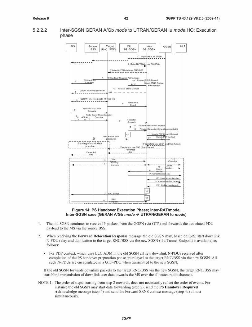
3GPP
3GPP TS 43.129 V8.2.0 (2009-11)42Release 8
5.2.2.2 Inter-SGSN GERAN A/Gb mode to UTRAN/GERAN Iu mode HO; Executionphase
4.
PS Handover Required Acknowledge
5. PS Handover
Command
8. Handover to UTRAN
Complete
1.IP packets to old SGSN
2.Relay N - PDUs to target RNC/ BSS
13. RAU
request
14. Security
functions
18.Insert subscriber data
19.Insert subscriber data ack
20.Update location ack
15. Update
location
21.RAU accept
22. RAU
Complete
16. Cancel
location
17. Cancel location ack
10.Forward Relocation Complete
12. BSS Packet Flow
procedures
9. Relocation
Complete
Forwarded
data
6
.GERAN Iu Access Bursts
,Physical Info
7. Relocation
Detect
8. Radio Bearer Reconfiguration
Complete
(
fo
r
GERAN
Iu)
6
.UTRAN Handover Execution
MS Source
BSS
Target
RNC / BSSHLRNew
3G -SGSN
Old
2G -SGSN
11.Update PDP Context Request
IP packets to new SGSN (no Direct Tunnel)
GGSN
10.
Forward Relocation Complete Acknowledge
4a.Forward SRNS Context
4a.F
orward SRNS Context
Acknowledge
4a.Forward SRNS Context
Sending of uplink data
possible
11. Update PDP Context
Response
Forwarded
data
C1
C2
C3
RAU
Procedure
IP packets to new RNC (Direct Tunnel)
2. Relay N-PDUs to new 3G-SGSN
Figure 14: PS Handover Execution Phase; Inter-RAT/mode,Inter-SGSN case (GERAN A/Gb mode UTRAN/GERAN Iu mode)
1. The old SGSN continues to receive IP packets from the GGSN (via GTP) and forwards the associated PDU
payload to the MS via the source BSS.
2. When receiving the Forward Relocation Response message the old SGSN may, based on QoS, start downlink
N-PDU relay and duplication to the target RNC/BSS via the new SGSN (if a Tunnel Endpoint is available) as
follows:
For PDP context, which uses LLC ADM in the old SGSN all new downlink N-PDUs received after
completion of the PS handover preparation phase are relayed to the target RNC/BSS via the new SGSN. All
such N-PDUs are encapsulated in a GTP-PDU when transmitted to the new SGSN.
If the old SGSN forwards downlink packets to the target RNC/BSS via the new SGSN, the target RNC/BSS may
start blind transmission of downlink user data towards the MS over the allocated radio channels.
NOTE 1: The order of steps, starting from step 2 onwards, does not necessarily reflect the order of events. For
instance the old SGSN may start data forwarding (step 2), send the PS Handover Required
Acknowledge message (step 4) and send the Forward SRNS context message (step 4a) almost
simultaneously.
3GPP
3GPP TS 43.129 V8.2.0 (2009-11)43Release 8
3. Void
4. The old SGSN continues the PS Handover by sending a PS Handover Required Acknowledge (TLLI, List of
Set Up PFCs, Source to Target Transparent Container) message to the source BSS.
Before sending the PS Handover Required Acknowledge message, the old SGSN, based on QoS, may
suspend downlink data transfer for any PDP contexts.
Before sending the PS Handover Command message to the MS the source BSS, based on QoS, may try to
empty the downlink BSS buffer for any BSS PFCs.
4a. The old SGSN shall send the Forward SRNS Context message (NSAPI, DL GTP-U number, UL GTP-U
number) to the new SGSN if there is at least one PDP context which requires "delivery order" to be
preserved.NSAPI identifies the PDP context to which the GTP-U numbers apply. The Forward SRNS
Context message is then acknowledged by the Forward SRNS Context Acknowledgemessage. The
Forward SRNS Context message contains the sequence numbers of the GTP-PDU next to be transmitted in
the uplink and downlink direction. After the Forward SRNS Context message is sent, further uplink N-PDUs
received by the old SGSN from the source BSS, relative to a PDP context which requires "delivery order" to be
preserved, shall not be forwarded to the GGSN.
The GTP-U numbers are only sent by the old SGSN for PDP context(s) requiring delivery order (QoS profile)
to be preserved. If delivery order is to be preserved (QoS) profile), consecutive GTP-PDU sequence numbering
shall be maintained through the lifetime of the PDP context(s).
Therefore, during the entire PS Handover procedure for the PDP context(s) using delivery order required (QoS
profile), the responsible GTP-U entities (old SGSN, target RNC and GGSN) shall assign consecutive
GTP-PDU sequence numbers to user packets belonging to the same PDP context uplink and downlink,
respectively.
The target RNC proceed as follows:
For RABs not requiring lossless PDCP the target RNC may, according the QoS profile of the PDP context,
store the received data until it receives confirmation of MS presence in the target cell.
The further target RNC/BSS behaviour is as specified in 3GPP TS 23.060 [19] (Combined Hard Handover
and SRNS Relocation).
5. The source BSS sends the PS Handover Command message containing theHandover to UTRAN
Command message (as specified in 3GPP TS 25.331 [17]) or Radio Bearer Reconfiguration message (asspecified in 3GPP TS 44.118 [16]) to the MS by interrupting the transmission of LLC PDUs on any of the
downlink TBFs. Following the transmission of this signalling message the source BSS may resume LLC PDU
transmission until it either has no more LLC PDUs to send or the PFC is released. Upon reception of the PS
Handover Command message the MS is not required to continue data reception in the source cell. Upon
reception of the PS Handover Command message the MS shall suspend the uplink transmission of user plane
data. MS management of uplink N-PDUs following the reception of the PS Handover Command message is
as follows:
All N-PDUs associated with a PFC receiving handover treatment that have not yet been fully transmitted
might be buffered depending on the QoS class.
Subsequent uplink N-PDUs that become available for transmission following the reception of the PS
Handover Command message might also be buffered depending on the QoS class.
For real time services uplink N-PDUs may be discarded by the MS during the link interruption.
NOTE 2: Any buffering should be performed before the data is passed to SNDCP in order to avoid header
compression on N-PDUs such that data delivery in the target cell may begin from the correct point in the
sequence.
6. MS is in the target cell and performs access to UTRAN as defined in 3GPP TS 25.331 [17] and to GERAN Iu
mode as defined in 3GPP TS 44.118 [16].
7. Target RNC/BSS sends a Relocation Detect message to the new SGSN to indicate that the MS is in the target
cell. The message shall be sent when the relocation execution trigger is received. For SRNS relocation type
"UE Involved", the relocation execution trigger may be received from the Uu interface; i.e. when the target

3GPP
3GPP TS 43.129 V8.2.0 (2009-11)44Release 8
RNC detects the MS on the lower layers. When the Relocation Detect message is sent, the target RNC shall
start serving RNC operation.
8. In UTRAN, MS sendsHandover to UTRAN Complete {Message Type, UE Information elements (Start List,
CN Domain Identity, Start), RB Information Elements (Count-C Activation Time)} message to the target RNC
(see 3GPP TS 25.331 [17]).
In GERAN Iu, MS sends Radio Bearer Reconfiguration Complete {RRC Transaction Identifier, IntegrityCheck Info, Uplink Integrity Protection Activation Info, COUNT-C Activation Time, Radio Bearer Uplink
Ciphering Activation Time Info, Mobile Observed Time Difference, Uplink Counter Synchronisation Info
struct, START List, CN Domain Identity, START, RB with PDCP Information List, RB with PDCP
Information} message to target BSS.
9. When the new source RNC-ID + S-RNTI are successfully exchanged with the MS, the target RNC/BSS shall
send the Relocation Complete message to the new SGSN. The purpose of the Relocation Complete procedureis to indicate by the target RNC/BSS the completion of the relocation of the source BSS to the CN. After the
reception of the Relocation Complete message the new SGSN shall be prepared to receive data from the target
RNC/BSS. Each uplink N-PDU received by the new SGSN is forwarded directly to the GGSN.
10. For inter-SGSN PS handover, the new SGSN sends a Forward Relocation Complete message to the old
SGSN to indicate the success of the handover procedure. The old SGSN acknowledges this with a Forward
Relocation Complete Acknowledge message. Upon the reception of the Forward Relocation Completemessage the old SGSN starts a packet forwarding timer. The old SGSN stops forwarding of data to the new
SGSN after the packet forwarding timer expires.
11. The new SGSN sends an Update PDP Context Request (new SGSN Address, TEID, QoS Negotiated)
message to the GGSN concerned. If a Direct Tunnel is established the SGSN provides to the GGSN instead of
the new SGSN Address and TEID, the RNC address for User Plane and TEID for Downlink data and shallinclude the DTI to instruct the GGSN to apply Direct Tunnel specific error handling procedure as defined in
3GPP TS 23.060 [19]. The GGSN updates the PDP context fields and returns an Update PDP Context
Response (TEID) message. From now on the GGSN sends new incoming downlink IP packets to the new
SGSN instead of to the old SGSN.
12. The old SGSN shall initiate PFC Management procedures towards the source cell in order to trigger the release
of resources in the source cell.
13. The MS sends a Routing Area Update Request (Old RAI, Old P-TMSI signature, Update Type) message to
the new SGSN informing it that the target cell belongs to a new routing area. The MS shall send this message
immediately after message 7. The new SGSN knows that a handover has been performed for this MS and can
therefore exclude the SGSN context procedures which normally are used within the RA Update procedure.
14. At this point the new SGSN may optionally invoke MS authentication (security function). The security
function can be deferred and performed at any later time as well.
NOTE 3: During an authentication procedure the SGSN has to suspend the downlink transmission of user data.
15. The new SGSN informs the HLR of the change of SGSN by sending Update Location (SGSN Number, SGSN
Address, IMSI) message to the HLR.
16. The HLR sends Cancel Location (IMSI, Cancellation Type) message to the old SGSN with Cancellation Type
set to Update Procedure.
17. The old SGSN acknowledges with a Cancel Location Acknowledge (IMSI) message. This message allows theold SGSN to know when to release the inter-SGSN tunnel.
18. The HLR sends Insert Subscriber Data (IMSI, GPRS subscription data) message to the new SGSN. The new
SGSN validates the MS presence in the (new) RA.
19. If all checks are successful then the new SGSN constructs an MM context for the MS and returns an Insert
Subscriber Data Acknowledge (IMSI) message to the HLR. This message allows the new SGSN to know
when to release the inter-SGSN tunnel.
20. The HLR acknowledges the Update Location by sending an Update Location Acknowledge (IMSI) message
to the new SGSN.
3GPP
3GPP TS 43.129 V8.2.0 (2009-11)45Release 8
21. The new SGSN validates the MS presence in the new RA. If the MS is allowed to be attached in this RA, the
SGSN updates the MM context for and sends a Routing Area Update Accept message to the MS.
22. The MS may respond to the SGSN with a Routing Area Update Complete message.
The following CAMEL procedure calls shall be performed (see referenced procedures in TS 23.078 [8b])
C1) CAMEL_GPRS_PDP_Context_Disconnection, CAMEL_GPRS_Detach and CAMEL_PS_Notification.
They are called in the following order:
- The CAMEL_GPRS_PDP_Context_Disconnection procedure is called several times: once per PDP
context. The procedure returns as result "Continue".
- Then the CAMEL_GPRS_Detach procedure is called once. The procedure returns as result "Continue".
- Then the CAMEL_PS_Notification procedure is called once. The procedure returns as result "Continue".
C2) CAMEL_GPRS_Routeing_Area_Update_Session and CAMEL_PS_Notification.
They are called in the following order:
- The CAMEL_GPRS_Routeing_Area_Update_Session procedure is called. The procedure returns as
result "Continue".
- Then, the CAMEL_PS_Notification procedure is called. The procedure returns as result "Continue".
C3) CAMEL_GPRS_Routeing_Area_Update_Context.
This procedure is called several times: once per PDP context. It returns as result "Continue".
For C2 and C3: refer to Routing Area Update procedure description in 3GPP TS 23.060.
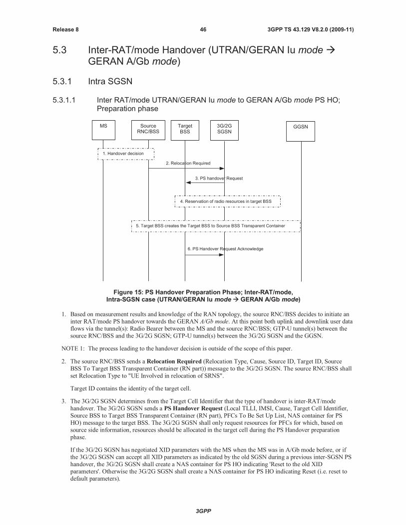
3GPP
3GPP TS 43.129 V8.2.0 (2009-11)46Release 8
5.3 Inter-RAT/mode Handover (UTRAN/GERAN Iu modeGERAN A/Gb mode)
5.3.1 Intra SGSN
5.3.1.1 Inter RAT/mode UTRAN/GERAN Iu mode to GERAN A/Gb mode PS HO;Preparation phase
2. Relocation Required
6. PS Handover Request Acknowledge
3. PS handover Request
MS SourceRNC/BSS
3G/2GSGSN
GGSNTargetBSS
1. Handover decision
5. Target BSS creates the Target BSS to Source BSS Transparent Container
4. Reservation of radio resources in target BSS
Figure 15: PS Handover Preparation Phase; Inter-RAT/mode,Intra-SGSN case (UTRAN/GERAN Iu mode GERAN A/Gb mode)
1. Based on measurement results and knowledge of the RAN topology, the source RNC/BSS decides to initiate an
inter RAT/mode PS handover towards the GERAN A/Gb mode. At this point both uplink and downlink user data
flows via the tunnel(s): Radio Bearer between the MS and the source RNC/BSS; GTP-U tunnel(s) between the
source RNC/BSS and the 3G/2G SGSN; GTP-U tunnel(s) between the 3G/2G SGSN and the GGSN.
NOTE 1: The process leading to the handover decision is outside of the scope of this paper.
2. The source RNC/BSS sends a Relocation Required (Relocation Type, Cause, Source ID, Target ID, Source
BSS To Target BSS Transparent Container (RN part)) message to the 3G/2G SGSN. The source RNC/BSS shall
set Relocation Type to "UE Involved in relocation of SRNS".
Target ID contains the identity of the target cell.
3. The 3G/2G SGSN determines from the Target Cell Identifier that the type of handover is inter-RAT/mode
handover. The 3G/2G SGSN sends a PS Handover Request (Local TLLI, IMSI, Cause, Target Cell Identifier,
Source BSS to Target BSS Transparent Container (RN part), PFCs To Be Set Up List, NAS container for PS
HO) message to the target BSS. The 3G/2G SGSN shall only request resources for PFCs for which, based on
source side information, resources should be allocated in the target cell during the PS Handover preparation
phase.
If the 3G/2G SGSN has negotiated XID parameters with the MS when the MS was in A/Gb mode before, or if
the 3G/2G SGSN can accept all XID parameters as indicated by the old SGSN during a previous inter-SGSN PS
handover, the 3G/2G SGSN shall create a NAS container for PS HO indicating 'Reset to the old XID
parameters'. Otherwise the 3G/2G SGSN shall create a NAS container for PS HO indicating Reset (i.e. reset to
default parameters).
3GPP
3GPP TS 43.129 V8.2.0 (2009-11)47Release 8
4. Based upon the ABQP for each PFC the target BSS makes a decision about which PFCs to assign radio
resources. The algorithm by which the BSS decides which PFCs that need resources is implementation specific.
Due to resource limitations not all downloaded PFCs will necessarily receive resource allocation. The target BSS
allocates TBFs for each PFC that can be accommodated by the target BSS.
After allocating radio resources the target BSS shall prepare the Target BSS to Source BSS Transparent
Container for the set up BSS PFCs.
5. The target BSS shall prepare the Target BSS to Source BSS Transparent Container which contains a PS
Handover Command including the CN part (NAS container for PS HO) and the RN part (PS Handover Radio
Resources).
6. The target BSS shall send the PS Handover Request Acknowledgemessage (Local TLLI, List of Set Up PFCs,
Target BSS to Source BSS Transparent Container) message to the 3G/2G SGSN. Upon sending the PS
Handover Request Acknowledge message the target BSS shall be prepared to receive downlink LLC PDUsfrom the 3G/2G SGSN for the accepted PFCs.
Any PDP contexts for which a PFC was not established are maintained in the 3G/2G SGSN and the related
SAPIs and PFIs are kept. These PDP contexts may be modified or deactivated by the 3G/2G SGSN via explicit
SM procedures upon the completion of the routing area update (RAU) procedure.
When the 3G/2G SGSN receives the PS Handover Request Acknowledge message and it decides to proceed
with the handover, the preparation phase is finished and the execution phase will follow.
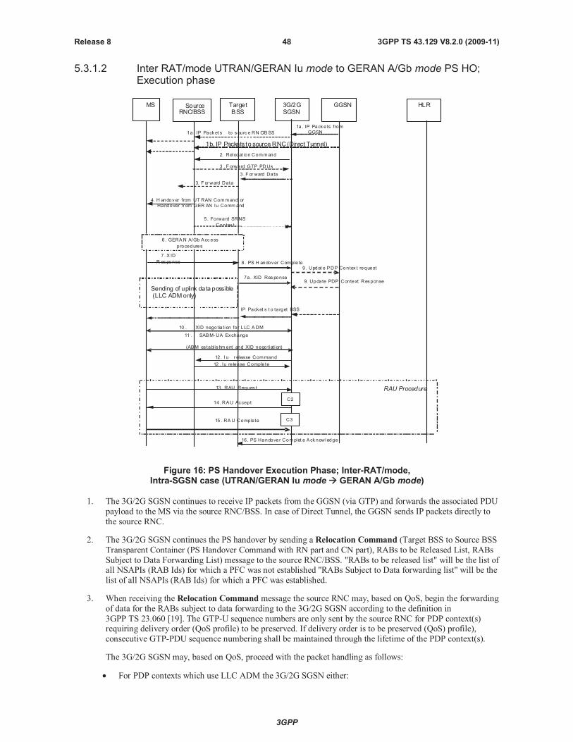
3GPP
3GPP TS 43.129 V8.2.0 (2009-11)48Release 8
5.3.1.2 Inter RAT/mode UTRAN/GERAN Iu mode to GERAN A/Gb mode PS HO;Execution phase
9. Updat e PDP Contex t request
2. Relocat ion Command
4. H andov er from UT RAN Command or
Handover fr om GER AN Iu Comm and
12. I u r elease Command
12 . Iu re lease Comple te
1a. IP Pack ets from
GGSN
3. F or ward Data
3 . F orward GTP PDUs
3. F orward Data
MS SourceRNC/BSS
TargetBSS
3G/2GSGSN
GGSN HLR
8. PS H andover Comple te
5 . Forward SRNS
Contex t
1a . IP Pack et s to s ourc e RN C/B SS
IP Packet s t o ta rget BSS
6. GERAN A/Gb Acc ess
procedures
Sending of uplink data possible(LLC ADMonly)
10 . XID negotia ti on fo r LLC ADM
7. X ID
R es ponse
13. RAU Reques t
14 . RAU Accept
RAU Procedure
15 . RAU Comple te
7a. XID Res ponse
11 . SABM-UA Exchange
(ABM es tabl ishm ent and XID negotiati on)
C2
C3
9. Update PDP Context Response
1b. IP Packets to source RNC (Direct Tunnel)
16. PS Handover Complet e Ack nowledge
Figure 16: PS Handover Execution Phase; Inter-RAT/mode,Intra-SGSN case (UTRAN/GERAN Iu mode GERAN A/Gb mode)
1. The 3G/2G SGSN continues to receive IP packets from the GGSN (via GTP) and forwards the associated PDU
payload to the MS via the source RNC/BSS. In case of Direct Tunnel, the GGSN sends IP packets directly to
the source RNC.
2. The 3G/2G SGSN continues the PS handover by sending a Relocation Command (Target BSS to Source BSS
Transparent Container (PS Handover Command with RN part and CN part), RABs to be Released List, RABs
Subject to Data Forwarding List) message to the source RNC/BSS. "RABs to be released list" will be the list ofall NSAPIs (RAB Ids) for which a PFC was not established "RABs Subject to Data forwarding list" will be the
list of all NSAPIs (RAB Ids) for which a PFC was established.
3. When receiving the Relocation Command message the source RNC may, based on QoS, begin the forwarding
of data for the RABs subject to data forwarding to the 3G/2G SGSN according to the definition in
3GPP TS 23.060 [19]. The GTP-U sequence numbers are only sent by the source RNC for PDP context(s)requiring delivery order (QoS profile) to be preserved. If delivery order is to be preserved (QoS) profile),
consecutive GTP-PDU sequence numbering shall be maintained through the lifetime of the PDP context(s).
The 3G/2G SGSN may, based on QoS, proceed with the packet handling as follows:
For PDP contexts which use LLC ADM the 3G/2G SGSN either:
3GPP
3GPP TS 43.129 V8.2.0 (2009-11)49Release 8
a. forwards the received downlink N-PDUs to the target BSS;
b. stores the received data into the SNDCP queue for e.g. the PDU lifetime;
c. discards the received data until e.g. reception of the PS Handover Complete message.
If the 3G/2G SGSN forwards packets to the target BSS, the target BSS may start a blind transmission of
downlink user data towards the MS over the allocated radio channels.
4. The RNC/BSS sends theHandover from UTRAN Command message (UTRAN) or theHandover fromGERAN Iu Command message to the MS where each message includes a PS Handover Command (RN part
and CN part) message. Before sending the message the uplink and downlink data transfer shall be suspended in
the source RNC for the RABs that require delivery order.
Upon reception of theHandover from UTRAN Command message (UTRAN) or theHandover from
GERAN Iu Command the MS shall suspend the uplink transmission of user plane data.
5. The source RNC/BSS continues the handover by sending a Forward SRNS Context (RAB contexts) message
to the 3G/2G SGSN.
The source RNC/BSS behaviour is as specified in 3GPP TS 23.060 [19] (Combined Hard Handover and SRNS
Relocation).
6. The MS executes the handover according to the parameters provided in the message delivered in step 4. The
procedure is the same as in step 6 in subclause 5.1.4.2.
7./7a. After accessing the cell using access bursts and receiving timing advance information from the BSS in step 6,
the MS processes the NAS container and then sends one XID Response message to the 3G/2G SGSN The MS
sends this message immediately after receiving the Packet Physical Information message containing the
timing advance or, in the synchronised network case, immediately if the PS Handover Accessmessage is not
required to be sent (see Section 6.2).
The MS shall resume the user data transfer only for those NSAPIs for which there are radio resources allocated
in the target cell. For NSAPIs using LLC ADM for which radio resources were not allocated in the target cell
the MS may request for radio resources using the legacy procedures.
NOTE: If the 3G/2G SGSN indicated Reset (i.e. reset to default parameters) in the NAS container for PS HO
included in theHandover from UTRAN Command message (UTRAN) or theHandover from
GERAN Iu Command message, in order to avoid collision cases the mobile station may avoid triggering
XID negotiation for any LLC SAPI used in LLC ADM, but wait for the SGSN to do so (see bullet 9). In
any case the mobile station may avoid triggering XID negotiation for any LLC SAPI used in LLC ABM,
but wait for the SGSN to do so (see bullet 10).
8. Upon reception of the first correct RLC/MAC block (sent in normal burst format) from the MS the target BSS
sends a PS Handover Complete (Local TLLI, IMSI, Request for Inter RAT Handover Info) message to
inform the 3G/2G SGSN that the MS has arrived in the target cell. Each uplink N-PDU received by the 3G/2G
SGSN via the target BSS is then forwarded directly to the GGSN. The target BSS shall request the INTER
RAT HANDOVER INFO from the SGSN by setting the “Request for INTER RAT HANDOVER INFO” to
“1”. The target BSS shall request the E-UTRAN INTER RAT HANDOVER INFO from the SGSN if it
supports inter-RAT PS handover to E-UTRAN and if it is missing the E-UTRAN INTER RAT HANDOVER
INFO.
9. If a Direct Tunnel was established for Iu mode, the SGSN sends an Update PDP Context Request (new
SGSN Address, TEID, QoS Negotiated) message to the GGSN with the indication for not re-negotiating the
QoS and to establish a tunnel between the SGSN and the GGSN. The GGSN updates the PDP context and
returns an Update PDP Context Response (TEID) message. From now on the GGSN sends new incoming
downlink IP packets to the SGSN.
10. If the 3G/2G SGSN indicated Reset (i.e. reset to default parameters) in the NAS container for PS HO included
in the Handover from UTRAN Command message (UTRAN) or theHandover from GERAN Iu
Command message, then on receipt of the PS Handover Complete message the SGSN initiates an
LLC/SNDCP XID negotiation for each LLC SAPI used in LLC ADM. In this case if the SGSN wants to use
the default parameters, it shall send an empty XID Command. If the SGSN indicated 'Reset to the old XID
parameters' in the NAS container for PS HO, no further XID negotiation is required for LLC SAPIs used in
LLC ADM only.
3GPP
3GPP TS 43.129 V8.2.0 (2009-11)50Release 8
11. The 3G/2G SGSN (re-)establishes LLC ABM for the PDP contexts which use acknowledged information
transfer. During the exchange of SABM and UA the SGSN shall perform LLC/SNDCP XID negotiation.
12. After the reception of the PS Handover Complete message the 3G/2G SGSN sends an Iu Release Command
message to the source RNC/BSS commanding the source RNC/BSS to release all resources related to the Iu
connection. When the RNC/BSS data forwarding timer has expired the source RNC/BSS responds with an Iu
Release Complete (RAB Data Volume report list, RABs released list) message.
13. The MS sends a Routing Area Update Request (Old P-TMSI, Old RAI, Old P-TMSI signature, Update Type)
message to the 3G/2G SGSN. This is done even if the target cell belongs to the same routing area as the source
cell. The MS shall send this message immediately after message 7, see 3GPP TS 23.060 [19].
The 3G/2G SGSN knows that a handover has been performed for this MS and can therefore exclude the SGSN
context procedures which normally are used within the RA Update procedure.
14. The 3G/2G SGSN validates the MS presence in the new RA. If the MS is allowed to be attached in this RA, the
3G/2G SGSN updates the MM context for and sends a Routing Area Update Accept (P-TMSI, TMSI,
P-TMSI signature, Receive N-PDU number) message to the MS. The Receive N-PDU Number contains the
acknowledgements for each acknowledged-mode NSAPI used by the 3G/2G SGSN, thereby confirming all
mobile originated N-PDUs successfully transferred before the start of the PS handover procedure.
15. The MS confirms the re-allocation of the new P-TMSI by responding to the 3G/2G SGSN with a Routing
Area Update Complete (Receive N-PDU number). The MS derives the TLLI from the new P-TMSI using the
current MM procedures. The Receive N-PDU Number contains the acknowledgements for each acknowledged
mode NSAPI used by the MS, thereby confirming all mobile terminated N-PDUs successfully transferred
before the start of the handover procedure. If Receive N-PDU Number confirms reception of N-PDUs that
were forwarded from the 3G/2G SGSN, these N-PDUs shall be discarded by the 3G/2G SGSN.
The following CAMEL procedure calls shall be performed (see referenced procedures in TS 23.078 [8b]):
C2) CAMEL_GPRS_Routeing_Area_Update_Session and CAMEL_PS_Notification.
They are called in the following order:
- The CAMEL_GPRS_Routeing_Area_Update_Session procedure is called. The procedure returns as
result "Continue".
- Then, the CAMEL_PS_Notification procedure is called. The procedure returns as result "Continue".
C3) CAMEL_GPRS_Routeing_Area_Update_Context.
This procedure is called several times: once per PDP context. It returns as result "Continue".
For C2 and C3: refer to Routing Area Update procedure description in 3GPP TS 23.060.
16. Upon reception of the PS Handover Complete message with the “Request for Inter RAT Handover Info” set to
“1” for UTRAN or E-UTRAN or both, the SGSN shall send PS Handover Complete Acknowledge (TLLI,
Inter RAT Handover Info, E-UTRAN Inter RAT Handover Info) message to the target BSS. This message will
contain at least one of the Inter RAT Handover information.
17. The target BSS receiving the PS Handover Complete Acknowledge message shall set the ‘Reliable INTER
RAT HANDOVER’ to ‘1’ in the PS Handover Requiredmessage in any subsequent PS handover to GERAN
A/Gb mode. The target BSS failing to receive the PS Handover Complete Acknowledge message shall set the
‘Reliable INTER RAT HANDOVER’ to ‘0’ in the PS Handover Requiredmessage in any subsequent PS
handover to GERAN A/Gb mode. The Target BSS shall, upon receipt of the INTER RAT HANDOVER INFO
in the PS Handover Complete Acknowledge message, discard the INTER RAT HANDOVER INFO received
from the source RNC during the preparation phase.
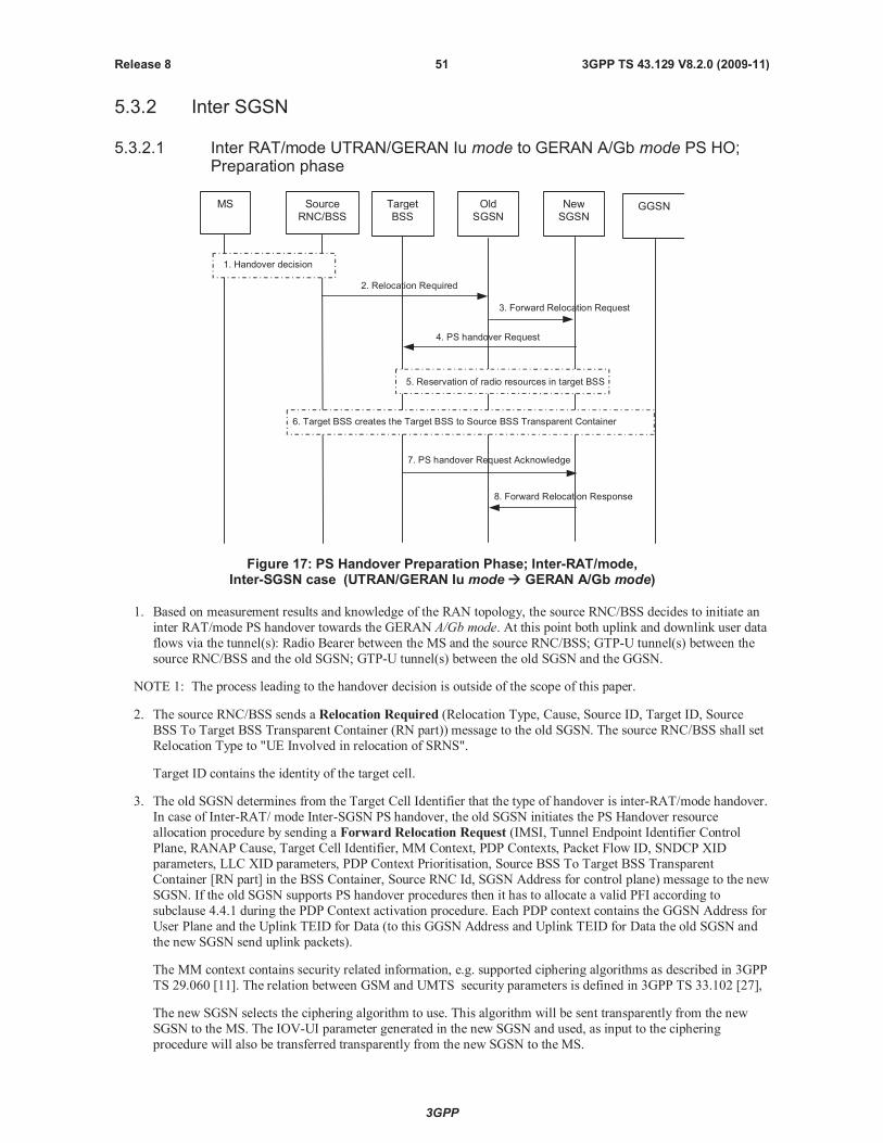
3GPP
3GPP TS 43.129 V8.2.0 (2009-11)51Release 8
5.3.2 Inter SGSN
5.3.2.1 Inter RAT/mode UTRAN/GERAN Iu mode to GERAN A/Gb mode PS HO;Preparation phase
2. Relocation Required
7. PS handover Request Acknowledge
3. Forward Relocation Request
4. PS handover Request
MS SourceRNC/BSS
OldSGSN
NewSGSN
GGSNTargetBSS
1. Handover decision
8. Forward Relocation Response
6. Target BSS creates the Target BSS to Source BSS Transparent Container
5. Reservation of radio resources in target BSS
Figure 17: PS Handover Preparation Phase; Inter-RAT/mode,Inter-SGSN case (UTRAN/GERAN Iu mode GERAN A/Gb mode)
1. Based on measurement results and knowledge of the RAN topology, the source RNC/BSS decides to initiate an
inter RAT/mode PS handover towards the GERAN A/Gb mode. At this point both uplink and downlink user data
flows via the tunnel(s): Radio Bearer between the MS and the source RNC/BSS; GTP-U tunnel(s) between the
source RNC/BSS and the old SGSN; GTP-U tunnel(s) between the old SGSN and the GGSN.
NOTE 1: The process leading to the handover decision is outside of the scope of this paper.
2. The source RNC/BSS sends a Relocation Required (Relocation Type, Cause, Source ID, Target ID, Source
BSS To Target BSS Transparent Container (RN part)) message to the old SGSN. The source RNC/BSS shall set
Relocation Type to "UE Involved in relocation of SRNS".
Target ID contains the identity of the target cell.
3. The old SGSN determines from the Target Cell Identifier that the type of handover is inter-RAT/mode handover.
In case of Inter-RAT/ mode Inter-SGSN PS handover, the old SGSN initiates the PS Handover resource
allocation procedure by sending a Forward Relocation Request (IMSI, Tunnel Endpoint Identifier Control
Plane, RANAP Cause, Target Cell Identifier, MM Context, PDP Contexts, Packet Flow ID, SNDCP XID
parameters, LLC XID parameters, PDP Context Prioritisation, Source BSS To Target BSS Transparent
Container [RN part] in the BSS Container, Source RNC Id, SGSN Address for control plane) message to the new
SGSN. If the old SGSN supports PS handover procedures then it has to allocate a valid PFI according to
subclause 4.4.1 during the PDP Context activation procedure. Each PDP context contains the GGSN Address for
User Plane and the Uplink TEID for Data (to this GGSN Address and Uplink TEID for Data the old SGSN and
the new SGSN send uplink packets).
The MM context contains security related information, e.g. supported ciphering algorithms as described in 3GPP
TS 29.060 [11]. The relation between GSM and UMTS security parameters is defined in 3GPP TS 33.102 [27],
The new SGSN selects the ciphering algorithm to use. This algorithm will be sent transparently from the new
SGSN to the MS. The IOV-UI parameter generated in the new SGSN and used, as input to the ciphering
procedure will also be transferred transparently from the new SGSN to the MS.
3GPP
3GPP TS 43.129 V8.2.0 (2009-11)52Release 8
When the new SGSN receives the Forward Relocation Request message the required PDP, MM, SNDCP and
LLC contexts are established and a new P-TMSI is allocated for the MS. When this message is received by the
new SGSN it begins the process of establishing PFCs for all PDP contexts.
When the new SGSN receives the Forward Relocation Request message it extracts from the PDP Contexts the
NSAPIs and SAPIs and PFIs to be used in the new SGSN. If for a given PDP Context the new SGSN does not
receive a PFI from the old SGSN, it shall not request the target BSS to allocate TBF resources corresponding to
that PDP Context. If none of the PDP Contexts forwarded from the old SGSN has a valid PFI allocated the new
SGSN shall consider this as a failure case and the request for PS handover shall be rejected.
In case when an SAPI and PFI was available at the old SGSN but the new SGSN does not support the same
SAPI and PFI for a certain NSAPI as the old SGSN, the new SGSN shall continue the PS handover procedure
only for those NSAPIs for which it can support the same PFI and SAPI as the old SGSN. All PDP contexts for
which no resources are allocated by the new SGSN or for which it cannot support the same SAPI and PFI
(i.e. the corresponding NSAPIs are not addressed in the response message of the target SGSN), are maintained
and the related SAPIs and PFIs are kept. These PDP contexts may be modified or deactivated by the new SGSN
via explicit SM procedures upon RAU procedure.
The old SGSN shall indicate the current XID parameter settings if available (i.e. those negotiated at the old
SGSN when the MS was in A/Gb mode or received during a previous inter-SGSN PS handover) to the new
SGSN. If the new SGSN can accept all XID parameters as indicated by the old SGSN, the new SGSN shall
create a NAS container for PS HO indicating 'Reset to the old XID parameters'. Otherwise, if the new SGSN
cannot accept all XID parameters indicated by the old SGSN or if no XID parameters were indicated by the old
SGSN, the new SGSN shall create a NAS container for PS HO indicating Reset (i.e. reset to default parameters).
4. The new SGSN sends a PS Handover Request (Local TLLI, IMSI, Cause, Target Cell Identifier, Source BSS to
Target BSS Transparent Container (RN part), PFCs To Be Set Up List, NAS container for PS HO) message to
the target BSS. The new SGSN shall not request resources for PFCs associated with PDP contexts with
maximum bit rate for uplink and downlink of 0 kbit/s or for which the Activity Status Indicator within the PDP
Context indicates that no active RAB exists on the source side.
5. Based upon the ABQP for each PFC the target BSS makes a decision about which PFCs to assign radio
resources. The algorithm by which the BSS decides which PFCs that need resources is implementation specific.
Due to resource limitations not all downloaded PFCs will necessarily receive resource allocation. The target BSS
allocates TBFs for each PFC that it can accommodate.
6. The target BSS shall prepare the Target BSS to Source BSS Transparent Container which contains a PS
Handover Command including the CN part (NAS container for PS HO) and the RN part (PS Handover Radio
Resources).
7. Target BSS shall send the PS Handover Request Acknowledge message (Local TLLI, List of Set Up PFCs,
Target BSS to Source BSS Transparent Container) message to the new SGSN. Upon sending the PS HandoverRequest Acknowledge message the target BSS shall be prepared to receive downlink LLC PDUs from the new
SGSN for the accepted PFCs.
Any PDP contexts for which a PFC was not established are maintained in the new SGSN and the related SAPIs
and PFIs are kept. These PDP contexts may be modified or deactivated by the new SGSN via explicit SM
procedures upon the completion of the routing area update (RAU) procedure.
8. The new SGSN passes the assigned list of TEIDs for each PDP context for which a PFC was assigned in the
RAB setup information IE in the Forward Relocation Response (Cause, List of Set Up PFCs, Target BSS to
Source BSS Transparent Container) in the BSS Container, Tunnel Endpoint Identifier Control Plane, SGSN
Address for User Traffic, Tunnel Endpoint Identifier Data II) message to the old SGSN. The NSAPIs of the
active PDP Contexts received in the Forward Relocation Request message for which the PS handover continues,
i.e. for which resources are allocated for the PFCs in the target BSS, are indicated in this message.
The Tunnel Endpoint Identifier Data II, one information for each PDP context, is the tunnel endpoint of the new
SGSN and is used for data forwarding from the old SGSN, via the new SGSN, to the target BSS.
The new SGSN activates the allocated LLC/SNDCP engines as specified in 3GPP TS 44.064 [21] for an SGSN
originated Reset or 'Reset to the old XID parameters'.
When the old SGSN receives the Forward Relocation Response message and it decides to proceed with the
handover, the preparation phase is finished and the execution phase will follow.
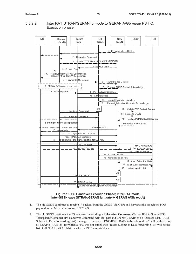
3GPP
3GPP TS 43.129 V8.2.0 (2009-11)53Release 8
5.3.2.2 Inter RAT UTRAN/GERAN Iu mode to GERAN A/Gb mode PS HO;Execution phase
2. Relocat ion Command
4. Handover from UTRAN Command orHandover from GERAN Iu Command
1. IP Packets to old SGSN
3. Forward Data
3 . Forward GTPPDUs
3. Forward Data
MS SourceRNC/BSS
Target
BSS
Old
SGSN
New
SGSN
GGSN HLR
8. PS Handover Complete7. XID Response
6. GERAN A/Gb Access procedures
10. Update PDP Context Request
10. Update PDP Context Response
9 . Forward Relocation Complete
9. Forward Relocation Complete Acknowledge
IPPackets to new SGSN
15. Update Locat ion
13. RAU Reques t
14. Security funct ions 14. Security functions
RAU Procedure
16 . Cancel Locat ion Ack
17 . Insert Subscriber Data
17. Insert Subscriber Data Ack
18. Update Locat ion Ack
19.RAU Accept
20.RAU Complete
16 . Cancel Location
5 . Forward SRNS Context5 . Forward SRNSContext
5. Forward SRNS Contex t Acknowledge
Sending of uplink data possible
12 . XID negotiat ion for LLC ADM
7a. XID Response
IP Packets to GGSN
11. Iu release Command
11. Iu release Complete
12a . SABM UA exchange
(re- es tablishment and XID negotiation for LLC ABM)
Forwarded data
Forwarded data
C1
C2
C3
Forward GTP PDUs3.
.21. PS Handover Complete Acknowledge
Figure 18: PS Handover Execution Phase; Inter-RAT/mode,Inter-SGSN case (UTRAN/GERAN Iu mode GERAN A/Gb mode)
1. The old SGSN continues to receive IP packets from the GGSN (via GTP) and forwards the associated PDU
payload to the MS via the source RNC/BSS.
2. The old SGSN continues the PS handover by sending a Relocation Command (Target BSS to Source BSS
Transparent Container (PS Handover Command with RN part and CN part), RABs to be Released List, RABs
Subject to Data Forwarding List) message to the source RNC/BSS. "RABs to be released list" will be the list of
all NSAPIs (RAB Ids) for which a PFC was not established "RABs Subject to Data forwarding list" will be the
list of all NSAPIs (RAB Ids) for which a PFC was established.
3GPP
3GPP TS 43.129 V8.2.0 (2009-11)54Release 8
3. When receiving the Relocation Command message the source RNC/BSS may, based on QoS, begin the
forwarding of data for the RABs subject to data forwarding to the new SGSN via the old SGSN (if a Tunnel
Endpoint is available) according to the definition in 3GPP TS 23.060 [19]. The GTP-U sequence numbers are
only sent by the source RNC for PDP context(s) requiring delivery order (QoS profile) to be preserved. If
delivery order is to be preserved (QoS) profile), consecutive GTP-PDU sequence numbering shall be
maintained through the lifetime of the PDP context(s).
The new SGSN may, based on QoS, proceed with the packet handling as follows:
For PDP contexts which use LLC ADM the new SGSN either:
a. forwards the received downlink N-PDUs to the target BSS;
b. stores the received data into the SNDCP queue for e.g. the PDU lifetime;
c. discards the received data until e.g. reception of the PS Handover Complete message.
If the new SGSN forwards packets to the target BSS, the target BSS may start a blind transmission of downlink
user data towards the MS over the allocated radio channels.
NOTE 1: The order of steps, starting from step 3 onwards, does not necessarily reflect the order of events. For
instance the source RNC may start data forwarding (step 3), send the RRC message (step 4) and send the
Forward SRNS Context message (step 5) almost simultaneously.
4. The source RNC/BSS sends theHandover from UTRAN Command message (UTRAN) or theHandover
from GERAN Iu Command message to the MS where each message includes a PS Handover Command (RNpart and CN part). Before sending the message the uplink and downlink data transfer shall be suspended in the
source RNC for the RABs that require delivery order.
Upon the reception of the HANDOVER from UTRAN Command message (UTRAN) or theHANDOVER
from GERAN Iu Command message containing the PS Handover Command message, the MS shall associate
its RAB IDs to the respective PFIs based on the relation with the NSAPI and shall suspend the uplinktransmission of the user plane data.
5. The source RNC continues the handover by sending a Forward SRNS Context (RAB contexts) message to
the new SGSN, via the old SGSN. The Forward SRNS Context message is acknowledged by the new SGSN
with the Forward SRNS Context Acknowledge message to the old SGSN.
The source RNC/BSS behaviour is as specified in 3GPP TS 23.060 [19] (Combined Hard Handover and SRNS
Relocation).
6. The MS executes the handover according to the parameters provided in the message delivered in step 4. The
procedure is the same as in step 6 in subclause 5.1.4.2 with the additional function of association of the
received PFI and existing RAB Id related to the particular NSAPI as described in clause 4.4.1.
7./7a. After accessing the cell using access bursts and receiving timing advance information from the BSS in step 6,
the MS processes the NAS container and then sends one XID Response message to the new SGSN . The MS
sends this message immediately after receiving the Packet Physical Information message containing thetiming advance or, in the synchronised network case, immediately if the PS Handover Accessmessage is not
required to be sent (see Section 6.2).
Upon sending the XID Response message, the MS shall resume the user data transfer only for those NSAPIs
for which there are radio resources allocated in the target cell. For NSAPIs using LLC ADM for which radio
resources were not allocated in the target cell the MS may request for radio resources using the legacyprocedures.
NOTE 2: If the new SGSN indicated Reset (i.e. reset to default parameters) in the NAS container for PS HO
included in the theHandover from UTRAN Command message (UTRAN) or theHandover from
GERAN Iu Command message, in order to avoid collision cases the mobile station may avoid triggering
XID negotiation for any LLC SAPI used in LLC ADM, but wait for the SGSN to do so (see bullet 12). In
any case the mobile station may avoid triggering XID negotiation for any LLC SAPI used in LLC ABM,but wait for the SGSN to do so (see bullet 12a).
8. Upon reception of the first correct RLC/MAC block (sent in normal burst format) from the MS the target BSS
sends a PS Handover Complete (Local TLLI, Handover Complete Status, Request for Inter RAT Handover
3GPP
3GPP TS 43.129 V8.2.0 (2009-11)55Release 8
Info) message to inform the new SGSN that the MS has arrived in the target cell. Each uplink N-PDU received
by the new SGSN via the target BSS is then forwarded directly to the GGSN. The target BSS shall request the
INTER RAT HANDOVER INFO from the SGSN by setting the ‘Request for Inter RAT Handover Info’ to ‘1’.
The target BSS shall request the E-UTRAN INTER RAT HANDOVER INFO from the SGSN if it supports
inter-RAT PS handover to E-UTRAN and if it is missing the E-UTRAN INTER RAT HANDOVER INFO.
9. Upon receiving the PS Handover Complete message, the new SGSN send a Forward Relocation Complete
message to the old SGSN to indicate completion of the PS handover procedures. The old SGSN responds with
a Forward Relocation Complete Acknowledge message.
10. The new SGSN sends an Update PDP Context Request (new SGSN Address, TEID, QoS Negotiated)
message to the GGSN concerned. The GGSN updates the PDP context fields and returns an Update PDP
Context Response (TEID) message. From now on the GGSN sends new incoming downlink IP packets to the
new SGSN instead of to the old SGSN.
11. The old SGSN sends an Iu Release Command message to the source RNC/BSS commanding the source
RNC/BSS to release all resources related to the Iu connection. When the RNC/BSS data forwarding timer has
expired the source RNC/BSS responds with an Iu Release Complete (RAB Data Volume report list, RABs
released list) message.
12. If the new SGSN indicated Reset (i.e. reset to default parameters) in the NAS container for PS HO included in
the Handover from UTRAN Command message (UTRAN) or theHandover from GERAN Iu Commandmessage, then on receipt of the PS Handover Complete the new SGSN initiates an LLC/SNDCP XID
negotiation for each LLC SAPI used in LLC ADM. In this case if the SGSN wants to use the default
parameters, it shall send an empty XID Command. If the new SGSN indicated 'Reset to the old XID
parameters' in the NAS container for PS HO, no further XID negotiation is required for LLC SAPIs used in
LLC ADM only.
12a. The new SGSN (re-)establishes LLC ABM for the PDP contexts which use acknowledged information
transfer. During the exchange of SABM and UA the SGSN shall perform LLC/SNDCP XID negotiation.
13. The MS sends a Routing Area Update Request (Old P-TMSI, Old RAI, Old P-TMSI signature, Update Type)
message to the new SGSN informing it that the source cell belongs to a new routing area. The MS shall send
this message immediately after message 7, see 3GPP TS 23.060 [19].
The new SGSN knows that a handover has been performed for this MS and can therefore exclude the SGSN
context procedures which normally are used within the RA Update procedure.
14. At this point the new SGSN may optionally invoke MS authentication (security function). The security
function can be deferred and performed at any later time as well.
NOTE 3: During an authentication procedure the SGSN has to suspend the downlink transmission of user data.
15. The new SGSN informs the HLR of the change of SGSN by sending Update Location (SGSN Number, SGSN
Address, IMSI) message to the HLR.
16. The HLR sends a Cancel Location (IMSI, Cancellation Type) message to the old SGSN with Cancellation
Type set to Update Procedure. The old SGSN acknowledges with a Cancel Location Acknowledge (IMSI)
message. This message allows the old SGSN to know when to release the inter-SGSN tunnel.
17. The HLR sends Insert Subscriber Data (IMSI, GPRS subscription data) message to the new SGSN. The new
SGSN validates the MS presence in the (new) RA. If all checks are successful then the new SGSN constructs
an MM context for the MS and returns an Insert Subscriber Data Acknowledge (IMSI) message to the HLR.This message allows the new SGSN to know when to release the inter-SGSN tunnel.
18. The HLR acknowledges the Update Location by sending an Update Location Acknowledge (IMSI) message
to the new SGSN.
19. The new SGSN validates the MS presence in the new RA. If the MS is allowed to be attached in this RA, the
SGSN updates the MM context for and sends a Routing Area Update Accept (P-TMSI, TMSI, P-TMSI
signature, Receive N-PDU number) message to the MS. The Receive N-PDU Number contains the
acknowledgements for each acknowledged-mode NSAPI used by the SGSN, thereby confirming all mobile
originated N-PDUs successfully transferred before the start of the PS handover procedure.

3GPP
3GPP TS 43.129 V8.2.0 (2009-11)56Release 8
20. The MS confirms the re-allocation of the new P-TMSI by responding to the SGSN with a Routing Area
Update Complete (Receive N-PDU number) message. The MS derives the Local TLLI from the new P-TMSI
using the current MM procedures. The Receive N-PDU Number contains the acknowledgements for each
acknowledged mode NSAPI used by the MS, thereby confirming all mobile terminated N-PDUs successfully
transferred before the start of the handover procedure. If Receive N-PDU Number confirms reception of
N-PDUs that were forwarded from the old SGSN, these N-PDUs shall be discarded by the new SGSN.
The following CAMEL procedure calls shall be performed (see referenced procedures in TS 23.078 [8b])
C1) CAMEL_GPRS_PDP_Context_Disconnection, CAMEL_GPRS_Detach and CAMEL_PS_Notification.
They are called in the following order:
- The CAMEL_GPRS_PDP_Context_Disconnection procedure is called several times: once per PDP
context. The procedure returns as result "Continue".
- Then the CAMEL_GPRS_Detach procedure is called once. The procedure returns as result "Continue"
- Then the CAMEL_PS_Notification procedure is called once. The procedure returns as result "Continue".
C2) CAMEL_GPRS_Routeing_Area_Update_Session and CAMEL_PS_Notification.
They are called in the following order:
- The CAMEL_GPRS_Routeing_Area_Update_Session procedure is called. The procedure returns as
result "Continue".
- Then, the CAMEL_PS_Notification procedure is called. The procedure returns as result "Continue".
C3) CAMEL_GPRS_Routeing_Area_Update_Context.
This procedure is called several times: once per PDP context. It returns as result "Continue".
For C2 and C3: refer to Routing Area Update procedure description in 3GPP TS 23.060.
21. Upon reception of the PS Handover Complete message with the “Request for Inter RAT Handover Info” set to
“1” for UTRAN or E-UTRAN or both, the SGSN shall send PS Handover Complete Acknowledge (TLLI,
Inter RAT Handover Info, E-UTRAN Inter RAT Handover Info) message to the target BSS. This message shall
contain at least one of the Inter RAT Handover information.
22. The target BSS receiving the PS Handover Complete Acknowledge message shall set the ‘Reliable INTER
RAT HANDOVER’ to ‘1’ in the PS Handover Requiredmessage in any subsequent PS handover to GERAN
A/Gb mode. The target BSS failing to receive the PS Handover Complete Acknowledge message shall set the
‘Reliable INTER RAT HANDOVER’ to ‘0’ in the PS Handover Requiredmessage in any subsequent PS
handover to GERAN A/Gb mode. The Target BSS shall, upon receipt of the INTER RAT HANDOVER INFO
in the PS Handover Complete Acknowledge message, discard the INTER RAT HANDOVER INFO received
from the source RNC during the preparation phase.
5.3a Inter-RAT Handover (GERAN A/Gb mode to E-UTRAN)
5.3a.1 General
This procedure and the corresponding signalling flows are defined in 3GPP TS23.401 [33].
For performing the inter-RAT handover from GERAN A/Gb mode to E-UTRAN the pre-conditions are:
- The MS is in packet transfer mode (GERAN A/Gb mode);
- The MS has at least one PDP Context established;
- The BSS supports PFM (Packet Flow Management) procedures.
3GPP
3GPP TS 43.129 V8.2.0 (2009-11)57Release 8
5.3a.2 Preparation phase
The detailed signalling flows are specified in 3GPP TS 23.401 [33] in sub-clause 5.5.2.4.2.
5.3a.3 Execution phase
The detailed signalling flows are specified in 3GPP TS 23.401 [33] in sub-clause 5.5.2.4.3.
5.3b Inter-RAT Handover (E-UTRAN to GERAN A/Gb mode)
5.3b.1 General
This procedure and the corresponding signalling flows are defined in 3GPP TS23.401 [33].
For performing the inter-RAT handover from E-UTRAN to GERAN A/Gb mode the pre-conditions are:
- The UE is in ECM-CONNECTED state (E-UTRAN Active mode);
- The BSS supports PFM (Packet Flow Management) procedures.
5.3b.2 Preparation phase
The detailed signalling flows are specified in 3GPP TS 23.401 [33] in sub-clause 5.5.2.3.2.
5.3b.3 Execution phase
The detailed signalling flows are specified in 3GPP TS 23.401 [33] in sub-clause 5.5.2.3.2.
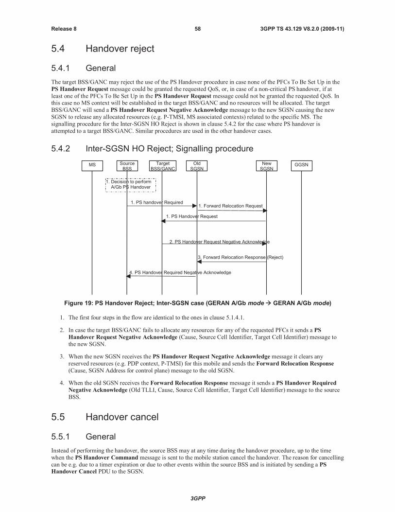
3GPP
3GPP TS 43.129 V8.2.0 (2009-11)58Release 8
5.4 Handover reject
5.4.1 General
The target BSS/GANC may reject the use of the PS Handover procedure in case none of the PFCs To Be Set Up in the
PS Handover Request message could be granted the requested QoS, or, in case of a non-critical PS handover, if at
least one of the PFCs To Be Set Up in the PS Handover Request message could not be granted the requested QoS. Inthis case no MS context will be established in the target BSS/GANC and no resources will be allocated. The target
BSS/GANC will send a PS Handover Request Negative Acknowledge message to the new SGSN causing the new
SGSN to release any allocated resources (e.g. P-TMSI, MS associated contexts) related to the specific MS. The
signalling procedure for the Inter-SGSN HO Reject is shown in clause 5.4.2 for the case where PS handover is
attempted to a target BSS/GANC. Similar procedures are used in the other handover cases.
5.4.2 Inter-SGSN HO Reject; Signalling procedure
MS TargetBSS/GANC
SourceBSS
OldSGSN
NewSGSN
GGSN
1. Forward Relocation Request
1. PS Handover Request
1. PS handover Required
3. Forward Relocation Response (Reject)
2. PS Handover Request Negative Acknowledge
1. Decision to performA/Gb PS Handover
4. PS Handover Required Negative Acknowledge
Figure 19: PS Handover Reject; Inter-SGSN case (GERAN A/Gb mode GERAN A/Gb mode)
1. The first four steps in the flow are identical to the ones in clause 5.1.4.1.
2. In case the target BSS/GANC fails to allocate any resources for any of the requested PFCs it sends a PS
Handover Request Negative Acknowledge (Cause, Source Cell Identifier, Target Cell Identifier) message to
the new SGSN.
3. When the new SGSN receives the PS Handover Request Negative Acknowledge message it clears any
reserved resources (e.g. PDP context, P-TMSI) for this mobile and sends the Forward Relocation Response
(Cause, SGSN Address for control plane) message to the old SGSN.
4. When the old SGSN receives the Forward Relocation Response message it sends a PS Handover Required
Negative Acknowledge (Old TLLI, Cause, Source Cell Identifier, Target Cell Identifier) message to the source
BSS.
5.5 Handover cancel
5.5.1 General
Instead of performing the handover, the source BSS may at any time during the handover procedure, up to the time
when the PS Handover Command message is sent to the mobile station cancel the handover. The reason for cancelling
can be e.g. due to a timer expiration or due to other events within the source BSS and is initiated by sending a PSHandover Cancel PDU to the SGSN.
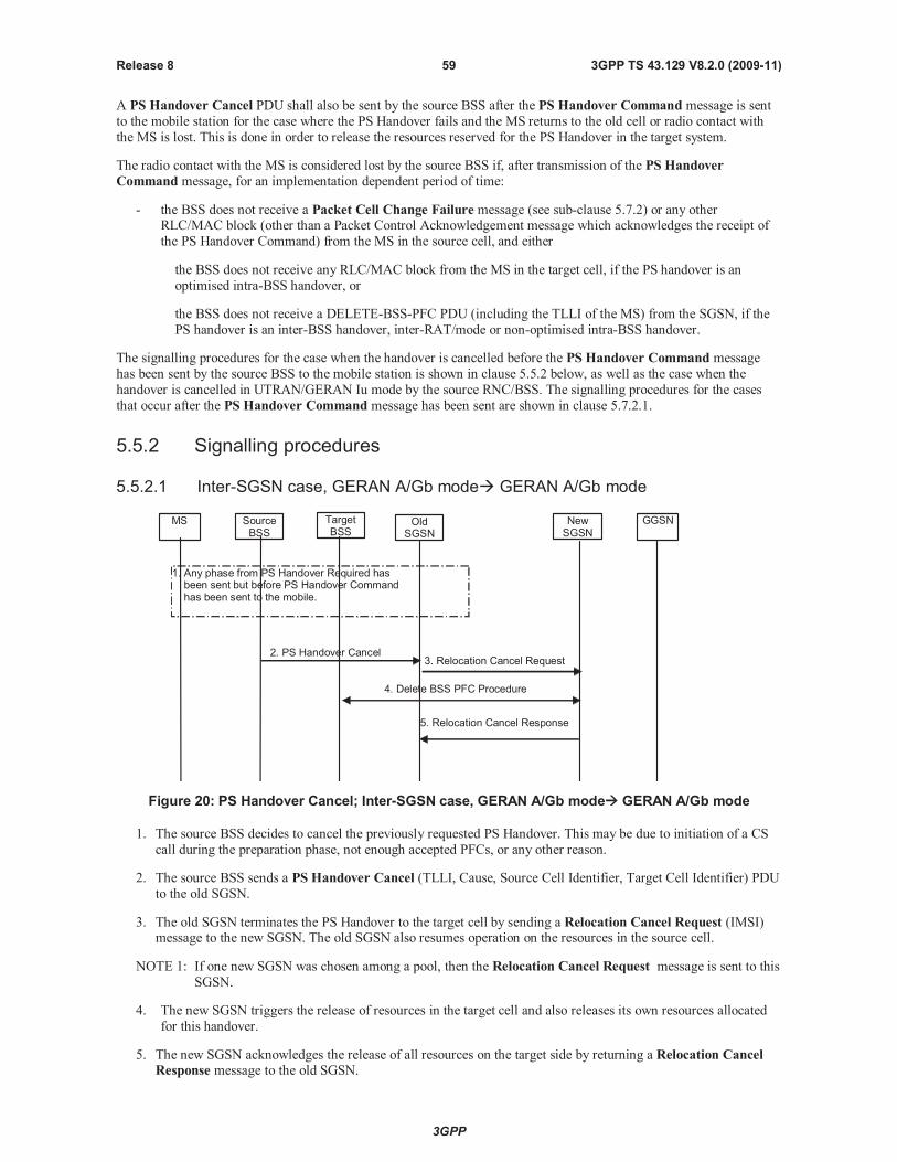
3GPP
3GPP TS 43.129 V8.2.0 (2009-11)59Release 8
A PS Handover Cancel PDU shall also be sent by the source BSS after the PS Handover Command message is sent
to the mobile station for the case where the PS Handover fails and the MS returns to the old cell or radio contact with
the MS is lost. This is done in order to release the resources reserved for the PS Handover in the target system.
The radio contact with the MS is considered lost by the source BSS if, after transmission of the PS Handover
Command message, for an implementation dependent period of time:
- the BSS does not receive a Packet Cell Change Failure message (see sub-clause 5.7.2) or any otherRLC/MAC block (other than a Packet Control Acknowledgement message which acknowledges the receipt of
the PS Handover Command) from the MS in the source cell, and either
the BSS does not receive any RLC/MAC block from the MS in the target cell, if the PS handover is an
optimised intra-BSS handover, or
the BSS does not receive a DELETE-BSS-PFC PDU (including the TLLI of the MS) from the SGSN, if the
PS handover is an inter-BSS handover, inter-RAT/mode or non-optimised intra-BSS handover.
The signalling procedures for the case when the handover is cancelled before the PS Handover Command message
has been sent by the source BSS to the mobile station is shown in clause 5.5.2 below, as well as the case when the
handover is cancelled in UTRAN/GERAN Iu mode by the source RNC/BSS. The signalling procedures for the cases
that occur after the PS Handover Command message has been sent are shown in clause 5.7.2.1.
5.5.2 Signalling procedures
5.5.2.1 Inter-SGSN case, GERAN A/Gb mode GERAN A/Gb mode
TargetBSS
OldSGSN
NewSGSN
GGSN
3. Relocation Cancel Request
5. Relocation Cancel Response
2. PS Handover Cancel
4. Delete BSS PFC Procedure
1. Any phase from PS Handover Required hasbeen sent but before PS Handover Commandhas been sent to the mobile.
SourceBSS
MS
Figure 20: PS Handover Cancel; Inter-SGSN case, GERAN A/Gb mode GERAN A/Gb mode
1. The source BSS decides to cancel the previously requested PS Handover. This may be due to initiation of a CS
call during the preparation phase, not enough accepted PFCs, or any other reason.
2. The source BSS sends a PS Handover Cancel (TLLI, Cause, Source Cell Identifier, Target Cell Identifier) PDU
to the old SGSN.
3. The old SGSN terminates the PS Handover to the target cell by sending a Relocation Cancel Request (IMSI)message to the new SGSN. The old SGSN also resumes operation on the resources in the source cell.
NOTE 1: If one new SGSN was chosen among a pool, then the Relocation Cancel Request message is sent to this
SGSN.
4. The new SGSN triggers the release of resources in the target cell and also releases its own resources allocated
for this handover.
5. The new SGSN acknowledges the release of all resources on the target side by returning a Relocation CancelResponse message to the old SGSN.

3GPP
3GPP TS 43.129 V8.2.0 (2009-11)60Release 8
NOTE 2: In the intra-SGSN case, the messages Relocation Cancel Request and Relocation Cancel Response are
not exchanged since the old and new SGSN are then the same node.
5.5.2.2 Inter-SGSN case, GERAN A/Gb mode UTRAN/GERAN Iu mode
TargetRNC
Old 2GSGSN
New 3GSGSN
GGSN
3. Relocation Cancel Request
6. Relocation Cancel Response
2. PS Handover Cancel
4. Iu Release Command
1. Any phase from PS Handover Required hasbeen sent but before PS Handover Commandhas been sent to the mobile.
SourceBSS
MS
5. Iu Release Complete
Figure 20a: PS Handover Cancel; Inter-SGSN case, GERAN A/Gb mode UTRAN/GERAN Iu mode
1. The source BSS decides to cancel the previously requested PS handover. This may be due to initiation of a CS
call during the preparation phase, not enough accepted PFCs, or any other reason.
2. The source BSS sends a PS Handover Cancel (TLLI, Cause, Source Cell Identifier, Target Cell Identifier) PDU
to the old SGSN.
3. The old SGSN terminates the PS Handover to the target cell by sending a Relocation Cancel Request (IMSI)
message to the new SGSN. The old SGSN also resumes operation on the resources in the source cell.
NOTE 1: If one new SGSN was chosen among a pool, then the Relocation Cancel Request message is sent to this
SGSN.
4. The new SGSN triggers the release of resources in the target cell by sending an Iu Release Command message
to the target RNC
5. The target RNC releases all resources allocated for this handover and returns an Iu Release Complete message
to the new SGSN.
6. The new SGSN releases its own resources allocated for this handover and acknowledges the release of all
resources on the target side by returning a Relocation Cancel Response message to the old SGSN.
NOTE 2: In the intra-SGSN case, the messages Relocation Cancel Request and Relocation Cancel Response are
not exchanged since the old and new SGSN are then the same node.
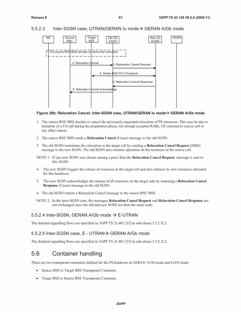
3GPP
3GPP TS 43.129 V8.2.0 (2009-11)61Release 8
5.5.2.3 Inter-SGSN case, UTRAN/GERAN Iu mode GERAN A/Gb mode
TargetBSS
Old 3GSGSN
New 2GSGSN
GGSN
3. Relocation Cancel Request
1. The source RNC/BSS decides to cancel the relocation..
SourceRNC
MS
5. Relocation Cancel Response
2. Relocation Cancel
4. Delete BSS PFC Procedure
6. Relocation Cancel Acknowledge
Figure 20b: Relocation Cancel; Inter-SGSN case, UTRAN/GERAN Iu mode GERAN A/Gb mode
1. The source RNC/BSS decides to cancel the previously requested relocation of PS resources. This may be due to
initiation of a CS call during the preparation phase, not enough accepted RABs, UE returned to source cell or
any other reason.
2. The source RNC/BSS sends a Relocation Cancel (Cause) message to the old SGSN.
3. The old SGSN terminates the relocation to the target cell by sending a Relocation Cancel Request (IMSI)
message to the new SGSN. The old SGSN also resumes operation on the resources in the source cell.
NOTE 1: If one new SGSN was chosen among a pool, then the Relocation Cancel Request message is sent to
this SGSN.
4. The new SGSN triggers the release of resources in the target cell and also releases its own resources allocated
for this handover.
5. The new SGSN acknowledges the release of all resources on the target side by returning a Relocation Cancel
Response (Cause) message to the old SGSN.
6. The old SGSN returns a Relocation Cancel message to the source RNC/BSS.
NOTE 2: In the intra-SGSN case, the messages Relocation Cancel Request and Relocation Cancel Response are
not exchanged since the old and new SGSN are then the same node.
5.5.2.4 Inter-SGSN, GERAN A/Gb mode E-UTRAN
The detailed signalling flows are specified in 3GPP TS 23.401 [33] in sub-clause 5.5.2.X.2.
5.5.2.5 Inter-SGSN case, E - UTRAN GERAN A/Gb mode
The detailed signalling flows are specified in 3GPP TS 23.401 [33] in sub-clause 5.5.2.X.2.
5.6 Container handling
There are two transparent containers defined for the PS handover in GERAN A/Gb mode and GAN mode:
Source BSS to Target BSS Transparent Container.
Target BSS to Source BSS Transparent Container.
3GPP
3GPP TS 43.129 V8.2.0 (2009-11)62Release 8
The Source BSS to Target BSS Transparent Container will carry the information to be transported transparently
between the source BSS and the target BSS/GANC and between the source GANC and the target BSS related to PS
handover.
The Target BSS to Source BSS Transparent Container will carry the information to be transported transparently
between the target BSS and the source BSS/GANC and between the target GANC and the source BSS related to PS
handover.
The generic handling of the source cell (GERAN A/Gb mode or UTRAN/GERAN Iu mode or E-UTRAN) to target cell
(GERAN A/Gb mode or UTRAN/GERAN Iu mode or E-UTRAN) radio-related container is as follows:
Created by the source BSS or RNC or eNB .
Processed by the target BSS or RNC or eNB.
Forwarded transparently by the SGSNs and MME .
The generic handling of the target cell (GERAN A/Gb mode or UTRAN/GERAN Iu mode or E-UTRAN ) to source cell
(GERAN A/Gb mode or UTRAN/GERAN Iu mode or E-UTRAN) radio-related container is as follows:
Created by the target BSS or RNC or eNB.
Processed by the source BSS or RNC or eNB .
Forwarded transparently by the SGSNs and MME .
The generic handling of the source cell to target cell radio-related container for PS handover from GERAN A/Gb modeto GAN mode or vice versa is as follows:
Created by the source BSS or GANC.
Processed by the target BSS for PS handover from a source GANC.
Processed by the target GANC for PS handover from a source BSS.
Forwarded transparently by the SGSNs.
The generic handling of the source cell to target cell radio-related container for PS handover from UTRAN to GAN
mode or vice versa is as follows:
Created by the source GANC or RNC.
Processed by the target GANC for PS handover from a source RNC.
Processed by the target RNC for PS handover from a source GANC.
Forwarded transparently by the SGSNs.
The generic handling of the target cell to source cell radio-related container for PS handover from GERAN A/Gb mode
to GAN mode or vice versa is as follows:
Created by the target GANC or BSS.
Processed by the source BSS for PS handover to a target GANC.
Processed by the source GANC for PS handover to a target BSS.
Forwarded transparently by the SGSNs.
The generic handling of the target cell to source cell radio-related container for PS handover from UTRAN to GAN
mode or vice versa is as follows:
Created by the target GANC or RNC.
Processed by the source RNC for PS handover to a target GANC.
3GPP
3GPP TS 43.129 V8.2.0 (2009-11)63Release 8
Processed by the source GANC for PS handover to a target RNC.
Forwarded transparently by the SGSNs.
5.6.1 Contents of the containers
The transparent container will consist of two parts:
The Radio Network part (RN part) carrying radio interface related parameters relevant for the MS and the radio
network (BSS/RNC/eNB ) and sent transparently through the core network; This content is:
- Created by the source BSS/RNC/GANC/eNB and carried in the Source BSS to Target BSS / Source to
Target transparent container (i.e. the forward container).
- Created by the target BSS/RNC/GANC/eNB and carried in the Target BSS to Source BSS / Target to Source
transparent container (i.e. the reverse container).
- Processed by the target BSS/RNC/GANC/eNB (forward container only)
- Processed by the source BSS/RNC/GANC/eNB and MS (reverse container only).
The Core Network part (CN part) carrying parameters relevant for the MS and the core network. This part isonly needed from the new SGSN to send to the MS for PS handover to A/Gb mode and GAN mode and thus is
only included in the Target BSS to Source BSS Transparent Container. This content is:
- Created by the new SGSN.
- Included in the Target BSS to Source BSS Transparent Container by the target BSS/GANC.
NOTE 1: The target BSS/GANC does not process the Core Network part.
- Forwarded transparently by the old SGSN and source BSS/RNC/GANC/eNB.
- Carried within the PS Handover Command message sent from the source BSS to the MS for PS handover
from A/Gb mode to A/Gb mode or for PS handover from A/Gb mode to GAN mode.
- Carried within the PS Handover Command message included within a GA-PSR Handover Command
message sent from the source GANC to the MS for PS handover from GAN mode to A/Gb mode.
- Carried within the PS Handover Command message included within a Handover from UTRAN
Command message or theHandover from GERAN Iu Command message sent from the source RNC to
the MS for PS handover from Iu mode to A/Gb mode.
- Carried within the PS Handover Command message included within a Handover from UTRAN
Command message sent from the source RNC to the MS for PS handover from UTRAN to GAN mode.
- Carried within the PS Handover Command message included within aMobilityFromEUTRACommand
message sent from the source eNB to the MS for PS handover from E-UTRAN to GERAN A/Gb mode.
- Processed by the MS.
The contents of the Radio Network part will depend on:
Type of channels that are subject to PS handover, i.e. shared or dedicated.
NOTE 2: Currently dedicated channels are not considered in the PS handover in GERAN A/Gb mode.
PS handover scenario, i.e. intra-mode or inter-RAT/mode.
Whether it is sent in a forward container or a reverse container.
The contents of the Core Network part will depend on the PS handover scenario, i.e. intra-mode or inter-RAT/mode.
3GPP
3GPP TS 43.129 V8.2.0 (2009-11)64Release 8
5.6.1.1 Contents of the GERAN A/Gb mode or GAN mode GERAN A/Gb modeTransparent Containers
5.6.1.1.1 Source BSS to Target BSS Transparent Container
In GERAN A/Gb mode/GAN mode -> GERAN A/Gb mode the Source BSS to Target BSS Transparent Container is
sent in the PSHandover Requiredmessage, the Forward Relocation Request message and the PS Handover
Request message.
The Radio Network part consists of the following:
MS RAC.
INTER RAT HANDOVER INFO (defined in 3GPP TS 25.331) containing the START_PS and UE RAC values,
if available.
E-UTRAN INTER RAT HANDOVER INFO (defined in 3GPP TS 48.018, see also 3GPP TS 36.331) if
available
NOTE 1: The START_PS and UE RAC are needed to support PS Handover to UTRAN/GERAN Iu mode.
NOTE 2: The way of transferring START_PS and UE RAC from the mobile station to the BSS/GANC, is to
piggyback the RRC container INTER RAT HANDOVER INFO, which includes START_PS and UE
RAC, to the Attach Complete and Routing Area Update Complete messages from the mobile station to
the SGSN. The SGSN will then include this container in every CREATE-BSS-PFC message sent to theBSS/GANC and/or in the PS Handover Complete Acknowledge message.
5.6.1.1.2 Target BSS to Source BSS Transparent Container
In GERAN A/Gb mode/GAN mode -> GERAN A/Gb mode the Target BSS to Source BSS Transparent Container is
sent in the PS Handover Request Acknowledgemessage, Forward Relocation Response message and the PS
Handover Required Acknowledge message.
The Radio Network part consists of the required information for access in the target cell and the information on
allocated radio resources, uplink and downlink TBF parameters, Handover reference and generic parameters for access
in the target cell (i.e. GPRS cell options, target cell "Cell Selection struct", global power control parameters, reference
frequency lists, cell allocation, GPRS mobile allocation).
The Core Network part (i.e. NAS Container for PS HO) consists of the following parameters:
an XID Command indicating Reset or 'Reset to old XID parameters' and the new IOV-UI for the target cell;
the GPRS ciphering algorithm to be used in the target cell, if it is different from the ciphering algorithm used in
the source cell.
5.6.1.2 Contents of the GERAN A/Gb mode or GAN mode UTRAN TransparentContainers
5.6.1.2.1 Source to Target Transparent Container
In GERAN A/Gb mode/GAN mode -> UTRAN the Source to Target Transparent Container is encoded as the Source
RNC to Target RNC Transaprent Container. It is sent from the source BSS/GANC to the target RNC in the PS
Handover Requiredmessage and the Relocation Request message.
The Radio Network part consists of the following:
RRC Container as defined in 3GPP TS 25.331 [17] will contain Inter RAT Handover Info (UTRAN specific
information including START_PS/UE RAC) and Inter RAT UE radio access capability including MS RAC from
BSS to RNC.
Target Cell Id.
Number of Iu instances IE. The value of this IE is set to 1 as defined in 3GPP TS 25.413 [23].
3GPP
3GPP TS 43.129 V8.2.0 (2009-11)65Release 8
Relocation Type. The value of the IE is set to “UE involved”, as defined in 3GPP TS 25.413 [23].
5.6.1.2.2 Target to Source Transparent Container
In GERAN A/Gb mode/GAN mode -> UTRAN the Target to Source Transparent Container is encoded as the Target
RNC to Source RNC Transparent Container. Itis sent from the target RNC to the source BSS/GANC in the RelocationRequest Acknowledge message, Forward Relocation Response message and the PS Handover Required
Acknowledge message.
The Radio Network part consists of the RRC message, i.e. theHandover to UTRAN Command message (as defined
in 3GPP TS 25.331 [17]) used to perform handover from GERAN A/Gb mode/GAN mode to UTRAN. This message
will be sent to the MS/UE within the PS Handover Command message (for PS handover from GERAN A/Gb mode)or within theGA-PSR Handover Command message (for PS handover from GAN mode).
5.6.1.3 Contents of the UTRAN GERAN A/Gb Mode or GAN mode TransparentContainers
5.6.1.3.1 Source BSS to Target BSS Transparent Container
In UTRAN -> GERAN A/Gb mode/GAN mode the Source BSS to Target BSS Transparent Container is sent from the
source RNC to the target BSS/GANC in the Relocation Required, Forward Relocation Request message and the PSHandover Request message in order to support inter-RAT PS handover from UTRAN (CELL_DCH state or
CELL_FACH state, only PS RABs established) to GERAN A/Gb mode/GAN mode.
The Radio Network part consists of the following information:
MS RAC.
INTER RAT HANDOVER INFO (defined in 3GPP TS 25.331) containing the START_PS and UE RAC values.
E-UTRAN INTER RAT HANDOVER INFO (defined in 3GPP TS 48.018, see also 3GPP TS 36.331) if
available
NOTE: The START_PS value received in the INTER RAT HANDOVER INFO is not always aligned with the
START_PS value stored in the MS after it has attached to the GSM network. The target BSS shall replace
the value received in the container received from the source RNC with the value received from the MS
via the SGSN (i.e. within a CREATE-BSS-PFC message or a PS Handover Complete Acknowledge
message).
5.6.1.3.2 Target BSS to Source BSS Transparent Container
In UTRAN -> GERAN A/Gb mode/GAN mode the Target BSS to Source BSS Transparent Container is sent from thetarget BSS/GANC to the source RNC in the PS Handover Request Acknowledge message, Forward Relocation
Response message and the Relocation Command message in order to support inter-RAT PS handover from UTRAN
(CELL_DCH state or CELL_FACH state, only PS RABs established) to GERAN A/Gb mode/GAN mode.
For PS handover from UTRAN to GERAN A/Gb mode the Radio Network part consist of the required information for
access in the target cell and the information on allocated radio resources: uplink and downlink TBF parameters, PS
Handover reference and generic parameters for access in the target cell (i.e. GPRS cell options, target cell "CellSelection struct", global power control parameters, reference frequency lists, cell allocation, GPRS mobile allocation).
Over the air interface this radio network container is sent within theHandover from UTRAN Command message.
For PS handover from UTRAN to GAN mode the Radio Network part consists only of the mandatory fields within the
PS Handover Radio Resources IE carried within the PS Handover Command message.
The Core Network part (i.e. NAS Container for PS HO) consist of the following parameters:
an XID Command indicating Reset or 'Reset to old XID parameters' and the new IOV-UI for the target cell;
the GPRS ciphering algorithm to be used in the target cell;
3GPP
3GPP TS 43.129 V8.2.0 (2009-11)66Release 8
5.6.1.4 Contents of the GERAN A/Gb mode GERAN Iu mode TransparentContainers
5.6.1.4.1 Source to Target Transparent Container
In GERAN A/Gb mode -> GERAN Iu mode the Source to Target Transparent Container is encoded as the Source RNC
to Target RNC Transparent Container. It is is sent from the source BSS to the target BSS (Iu) in the PS Handover
Requiredmessage, Forward Relocation Request message and the Relocation Request message.
The Radio Network part consists of:
RRC Container as defined in 3GPP TS 44.118 [16] shall contain START_PS /MS GERAN IU capabilities.
Target Cell Id.
Number of Iu instances. The value of the IE is set to 1 as defined in 3GPP TS 25.413 [23].
Relocation Type. The value of the IE is set to “UE involved”, as defined in 3GPP TS 25.413 [23].
5.6.1.4.2 Target to Source Transparent Container
In GERAN A/Gb mode -> GERAN Iu mode the Target to Source Transparent Container is encoded as the Target RNC
to Source RNC Transparent Conatiner. It is sent from the target BSS (Iu) to source BSS in the Relocation Request
Acknowledge message, Forward Relocation Response message and the PS Handover Required Acknowledge
message.
The Radio Network Part consist of the RRC message used in GERAN Iu mode to perform handover, i.e. Radio Bearer
Reconfiguration message as defined in 3GPP TS 44.118 [16]. This message will be sent to the MS in the PS
Handover Command message.
5.6.1.5 Content of GERAN Iu mode GERAN A/Gb mode Transparent Containers
5.6.1.5.1 Source BSS to Target BSS Transparent Container
In GERAN Iu mode -> GERAN A/Gb mode the Source BSS to Target BSS Transparent Container is sent from the
source BSS (Iu) to the target BSS in the Relocation Required message, Forward Relocation Request message and
the PS Handover Request message.
The Radio Network part consists of the following:
MS RAC.
INTER RAT OR MODE HANDOVER INFO with MS capabilities as defined in 3GPP TS 44.118 [16].
NOTE: START_PS and UE RAC shall be added to this IE.
5.6.1.5.2 Target BSS to Source BSS Transparent Container
In GERAN Iu mode -> GERAN A/Gb mode the Target BSS to Source BSS Transparent Container is sent from the
target BSS to the source BSS (Iu) in the PS Handover Request Acknowledge message, Forward Relocation
Response message and the Relocation Command message in order to support PS handover to GERAN A/Gb mode
from GERAN Iu mode (RRC Cell_Dedicated state or RRC CELL_Shared state, only PS RABs established).
The Radio Network part consists of the required information for access in the target cell and the information on
allocated radio resources: Uplink and downlink TBF parameters, PS Handover reference and generic parameters for
access in the target cell (i.e. GPRS cell options, target cell "Cell Selection struct", global power control parameters,
reference frequency lists, cell allocation, GPRS mobile allocation). Over the air interface this information is sent in the
Handover from GERAN Iu mode Command message.
The Core Network (i.e. NAS Container for PS HO) part consists of the following parameters:
an XID Command indicating Reset or 'Reset to old XID parameters' and the new IOV-UI for the target cell;
3GPP
3GPP TS 43.129 V8.2.0 (2009-11)67Release 8
the GPRS ciphering algorithm to be used in the target cell
5.6.1.6 Contents of the GERAN A/Gb mode GAN mode Transparent Containers
5.6.1.6.1 Source BSS to Target BSS Transparent Container
In GERAN A/Gb mode -> GAN mode the Source BSS to Target BSS Transparent Container is sent in the PS
Handover Requiredmessage, the Forward Relocation Request message and the PS Handover Request message.
The Radio Network part consists of the following:
MS RAC.
START_PS and UE RAC (for dual mode mobile stations).
NOTE 1: The START_PS and UE RAC are needed to support PS Handover to UTRAN/GERAN Iu mode.
NOTE 2: The way of transferring START_PS and UE RAC from the mobile station to the BSC, is to piggyback theRRC container INTER RAT HANDOVER INFO, which includes START_PS and UE RAC, to the
Attach Complete and Routing Area Update Complete messages from the mobile station to the SGSN. The
SGSN will then include this container in every CREATE-BSS-PFC message sent to the BSC.
5.6.1.6.2 Target BSS to Source BSS Transparent Container
In GERAN A/Gb mode -> GAN mode the Target BSS to Source BSS Transparent Container is sent in the PS
Handover Request Acknowledge message, Forward Relocation Response message and the PS Handover Required
Acknowledge message.
The Radio Network part consists only of the mandatory fields within the PS Handover Radio Resources IE carried
within the PS Handover Command message.
The Core Network part (i.e. NAS Container for PS HO) consists of the following parameters:
an XID Command indicating Reset or 'Reset to old XID parameters' and the new IOV-UI for the target cell;
the GPRS ciphering algorithm to be used in the target cell, if it is different from the ciphering algorithm used in
the source cell.
5.6.1.7 Contents of the GERAN A/Gb mode E-UTRAN Transparent Containers
5.6.1.7.1 Source to Target Transparent Container
In GERAN A/Gb mode to E-UTRAN handover the Source to Target Transparent Container is encoded as the Source
eNB to Target eNB Transparent Container. It is sent from the Source BSS to the target eNB in the PS Handover
Requiredmessage, the Forward Relocation Request message and the Handover Request message.
The Radio Network part consists of:
- MS RAC
- INTER RAT HANDOVER INFO (defined in 3GPP TS 25.331) containing the START_PS and UE RAC values,
if available
- E-UTRAN INTER RAT HANDOVER INFO (defined in 3GPP TS 48.018, see also 3GPP TS 36.331)
- Target Cell Id.
5.6.1.7.2 Target to Source Transparent Container
In GERAN A/Gb mode to E-UTRAN handover the Target to Source Transparent Conatiner is encoded as the Target
eNB to Source eNB Transparent Container. It is sent from the target eNB to source BSS in theHandover Request
Acknowledge message, the Forward Relocation Response message and the PS Handover Required Acknowledge
message.
3GPP
3GPP TS 43.129 V8.2.0 (2009-11)68Release 8
The Radio Network Part consists of the RRC message used in E-UTRAN to perform handover, i.e.
RRCConnectionReconfiguration message as defined in 3GPP TS 36.331 [31]. This message will be sent to the MS in
the PS Handover Command message.
5.6.1.8 Contents of the E-UTRAN GERAN A/Gb mode Transparent Containers
5.6.1.8.1 Source BSS to Target BSS Transparent Container
In E-UTRAN to GERAN A/Gb mode handover the Source BSS to Target BSS Transparent Container is sent from the
Source eNB to the Target BSS in theHandover Requiredmessage, the Forward Relocation Request message and
the PS Handover Request message
The Radio Network part consists of the following information:
- MS RAC IE.
- INTER RAT HANDOVER INFO (defined in 3GPP TS 25.331) containing the START_PS and UE RAC values,
if available.
- E-UTRAN INTER RAT HANDOVER INFO (defined in 3GPP TS 48.018, see also 3GPP TS 36.331).
5.6.1.8.2 Target BSS to Source BSS Transparent Container
In E-UTRAN to GERAN A/Gb mode handover the Target BSS to Source BSS Transparent Container is sent from the
Target BSS to the Source eNB in the PS Handover Request Acknowledge message, the Forward Relocation
Response message and theHandover Command message.
For PS handover from E-UTRAN to GERAN A/Gb mode the Radio Network part consist of the required information
for access in the target cell and the information on allocated radio resources: uplink and downlink TBF parameters, PS
Handover reference and generic parameters for access in the target cell (i.e. GPRS cell options, target cell "CellSelection struct", global power control parameters, reference frequency lists, cell allocation, GPRS mobile allocation).
Over the air interface this radio network container is sent within theMobilityFromEUTRACommand message.
The Core Network part (i.e. NAS Container for PS HO) consists of the following parameters:
- an XID Command indicating Reset or 'Reset to old XID parameters' and the new IOV-UI for the target cell;
- the GPRS ciphering algorithm to be used in the target cell.
5.7 PS Handover Failure
During the PS handover procedure several types of failures can be identified. The PS handover failures may be typical
network and signalling failure occurrences such as failures related to the loss of signalling messages, incorrectinformation element in the signalling messages or failures due to network nodes failures or specific to abnormal cases
occurring during PS handover procedures.
In general the PS handover failures can be divided into:
Preparation Phase Failure Scenarios on the Um, Gb, Gn and Up interface.
Execution Phase Failure Scenarios on the Um, Gb and Gn interface.
NOTE: RAU procedure failures will be handled as specified in 3GPP TS 24.008 [15].
A list of appropriate cause values should be chosen/defined to indicate to the source cell and target cell nodes the cause
of the PS Handover Request Negative Acknowledge and the PS handover Cancel messages.
3GPP
3GPP TS 43.129 V8.2.0 (2009-11)69Release 8
5.7.1 Preparations Phase Failure Scenarios
5.7.1.1 PS Handover preparation phase failure scenarios on the Um interface
No Resource Reservation / Allocation:
- No radio resources available in the target cell.
5.7.1.2 PS Handover preparation phase failure scenarios on the Gb interface
No Resource Reservation / Allocation on the target system:
- No radio resources available in the target cell (see clause 5.4). Appropriate cause values are needed in the PS
Handover Request Negative Acknowledge message.
Insufficient resource allocation by the target system:
- In case of insufficient resource allocation by the target side the source BSS may cancel the PS handoverprocedure (see clause 5.5).
Feature "PS Handover" not supported:
- A new cause value is needed for the Gb interface if the target BSS/GANC does not support the PS Handover
procedure.
Generic Causes:
- Generic causes for the Gb interface failures are defined in 3GPP TS 48.018 [10]. The same cause values are
applicable to the PS handover procedure on the Gb interface.
5.7.1.3 PS Handover preparation phase failure scenarios on the Gn interface
Context Transfer Failure:
- Context transfer failure may occur due to various causes defined in 3GPP TS 29.060 [11]. These cause values
will be utilized during PS handover procedure. These values are to be utilized during PS handover procedure
to indicate to the old SGSN the cause of the PS handover reject. Consequently an appropriate cause valueshould be chosen to allow the old SGSN to indicate to the source BSS the cause of failure.
No Resource Reservation/ No Resource Allocation:
- Resource Reservation/Allocation failure occurs when no radio resources are available in the target cell.
Consequently an appropriate cause value should be chosen to allow the old SGSN to indicate to the source
BSS the cause of failure.
Procedure "PS Handover" not supported:
- This occurs when the new SGSN does not support the PS Handover feature.
Generic Causes:
- In 3GPP TS 29.060 [11] a set of cause values are defined. The same cause values are applicable to the PS
handover procedure on the Gn interface.
5.7.1.4 PS Handover preparation phase failure scenarios on the Up interface
Failure to allocate a GA-PSR Transport Channel
- This occurs when the GANC sends the MS a GA-PSR ACTIVATE UTC REQ message (GANC MS) but
fails to receive a GA-PSR ACTIVATE UTC ACK back from the MS.
Generic Causes:
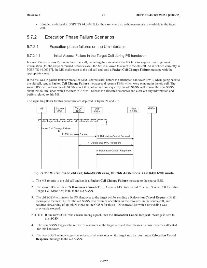
3GPP
3GPP TS 43.129 V8.2.0 (2009-11)70Release 8
- Handled as defined in 3GPP TS 44.060 [7] for the case where no radio resources are available in the target
cell.
5.7.2 Execution Phase Failure Scenarios
5.7.2.1 Execution phase failures on the Um interface
5.7.2.1.1 Initial Access Failure in the Target Cell during PS handover
In case of initial access failure in the target cell, including the case where the MS fails to acquire time alignment
information (for the unsynchronised network case), the MS is allowed to revert to the old cell. As is defined currently in
3GPP TS 44.060 [7], the MS shall return to the old cell and send a Packet Cell Change Failure message with the
appropriate cause.
If the MS was in packet transfer mode (or MAC-shared state) before the attempted handover it will, when going back to
the old cell, send a Packet Cell Change Failure message and resume TBFs which were ongoing in the old cell. The
source BSS will inform the old SGSN about this failure and consequently the old SGSN will inform the new SGSN
about this failure, upon which the new SGSN will release the allocated resources and clear out any information and
buffers related to this MS.
The signalling flows for this procedure are depicted in figure 21 and 21a.
TargetBSS
OldSGSN
NewSGSN
GGSN
3. Relocation Cancel Request
5. Relocation Cancel Response
2. PS Handover Cancel
4. Delete BSS PFC Procedure
1. Initial target cell access failure. MS returns to old cell.
SourceBSS
MS
1. Packet Cell Change Failure
Figure 21: MS returns to old cell; Inter-SGSN case, GERAN A/Gb mode GERAN A/Gb mode
1. The MS returns to the old cell and sends a Packet Cell Change Failure message to the source BSS.
2. The source BSS sends a PS Handover Cancel (TLLI, Cause = MS Back on old Channel, Source Cell Identifier,
Target Cell Identifier) PDU to the old SGSN.
3. The old SGSN terminates the PS Handover to the target cell by sending a Relocation Cancel Request (IMSI)
message to the new SGSN. The old SGSN also resumes operation on the resources in the source cell, and
resumes forwarding of uplink N-PDUs to the GGSN for those PDP contexts for which forwarding was
previously stopped.
NOTE 1: If one new SGSN was chosen among a pool, then the Relocation Cancel Request message is sent to
this SGSN.
4. The new SGSN triggers the release of resources in the target cell and also releases its own resources allocated
for this handover.
5. The new SGSN acknowledges the release of all resources on the target side by returning a Relocation Cancel
Response message to the old SGSN.
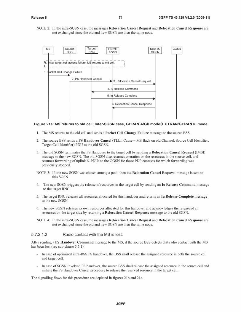
3GPP
3GPP TS 43.129 V8.2.0 (2009-11)71Release 8
NOTE 2: In the intra-SGSN case, the messages Relocation Cancel Request and Relocation Cancel Response are
not exchanged since the old and new SGSN are then the same node.
TargetRNC
Old 2GSGSN
New 3GSGSN
GGSN
3. Relocation Cancel Request
6. Relocation Cancel Response
2. PS Handover Cancel
1. Initial target cell access failure. MS returns to old cell.
SourceBSS
MS
1. Packet Cell Change Failure
4. Iu Release Command
5. Iu Release Complete
Figure 21a: MS returns to old cell; Inter-SGSN case, GERAN A/Gb mode UTRAN/GERAN Iu mode
1. The MS returns to the old cell and sends a Packet Cell Change Failure message to the source BSS.
2. The source BSS sends a PS Handover Cancel (TLLI, Cause = MS Back on old Channel, Source Cell Identifier,
Target Cell Identifier) PDU to the old SGSN.
3. The old SGSN terminates the PS Handover to the target cell by sending a Relocation Cancel Request (IMSI)
message to the new SGSN. The old SGSN also resumes operation on the resources in the source cell, and
resumes forwarding of uplink N-PDUs to the GGSN for those PDP contexts for which forwarding was
previously stopped.
NOTE 3: If one new SGSN was chosen among a pool, then the Relocation Cancel Request message is sent to
this SGSN.
4. The new SGSN triggers the release of resources in the target cell by sending an Iu Release Command message
to the target RNC
5. The target RNC releases all resources allocated for this handover and returns an Iu Release Complete message
to the new SGSN.
6. The new SGSN releases its own resources allocated for this handover and acknowledges the release of all
resources on the target side by returning a Relocation Cancel Response message to the old SGSN.
NOTE 4: In the intra-SGSN case, the messages Relocation Cancel Request and Relocation Cancel Response are
not exchanged since the old and new SGSN are then the same node.
5.7.2.1.2 Radio contact with the MS is lost:
After sending a PS Handover Command message to the MS, if the source BSS detects that radio contact with the MS
has been lost (see sub-clause 5.5.1):
- In case of optimised intra-BSS PS handover, the BSS shall release the assigned resource in both the source cell
and target cell.
- In case of SGSN involved PS handover, the source BSS shall release the assigned resource in the source cell and
initiate the PS Handover Cancel procedure to release the reserved resource in the target cell.
The signalling flows for this procedure are depicted in figures 21b and 21c.
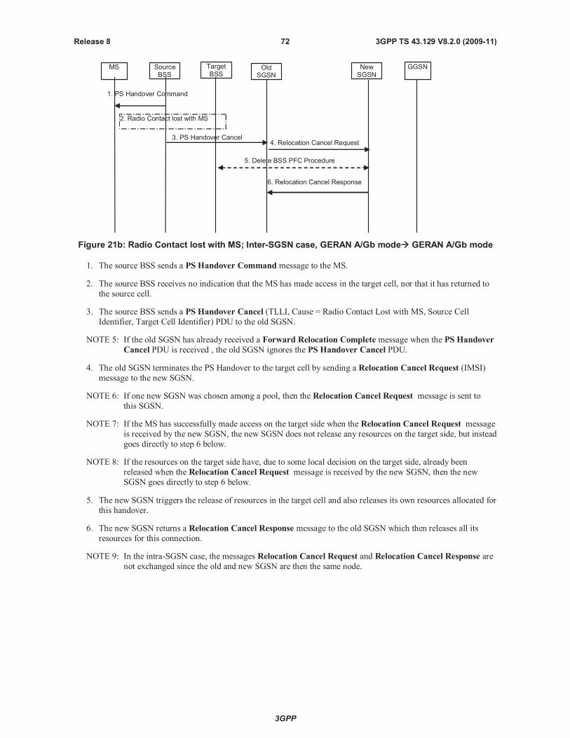
3GPP
3GPP TS 43.129 V8.2.0 (2009-11)72Release 8
TargetBSS
OldSGSN
NewSGSN
GGSN
4. Relocation Cancel Request
6. Relocation Cancel Response
3. PS Handover Cancel
5. Delete BSS PFC Procedure
2. Radio Contact lost with MS
SourceBSS
MS
1. PS Handover Command
Figure 21b: Radio Contact lost with MS; Inter-SGSN case, GERAN A/Gb mode GERAN A/Gb mode
1. The source BSS sends a PS Handover Command message to the MS.
2. The source BSS receives no indication that the MS has made access in the target cell, nor that it has returned to
the source cell.
3. The source BSS sends a PS Handover Cancel (TLLI, Cause = Radio Contact Lost with MS, Source Cell
Identifier, Target Cell Identifier) PDU to the old SGSN.
NOTE 5: If the old SGSN has already received a Forward Relocation Complete message when the PS Handover
Cancel PDU is received , the old SGSN ignores the PS Handover Cancel PDU.
4. The old SGSN terminates the PS Handover to the target cell by sending a Relocation Cancel Request (IMSI)
message to the new SGSN.
NOTE 6: If one new SGSN was chosen among a pool, then the Relocation Cancel Request message is sent to
this SGSN.
NOTE 7: If the MS has successfully made access on the target side when the Relocation Cancel Request message
is received by the new SGSN, the new SGSN does not release any resources on the target side, but instead
goes directly to step 6 below.
NOTE 8: If the resources on the target side have, due to some local decision on the target side, already been
released when the Relocation Cancel Request message is received by the new SGSN, then the new
SGSN goes directly to step 6 below.
5. The new SGSN triggers the release of resources in the target cell and also releases its own resources allocated for
this handover.
6. The new SGSN returns a Relocation Cancel Response message to the old SGSN which then releases all its
resources for this connection.
NOTE 9: In the intra-SGSN case, the messages Relocation Cancel Request and Relocation Cancel Response are
not exchanged since the old and new SGSN are then the same node.
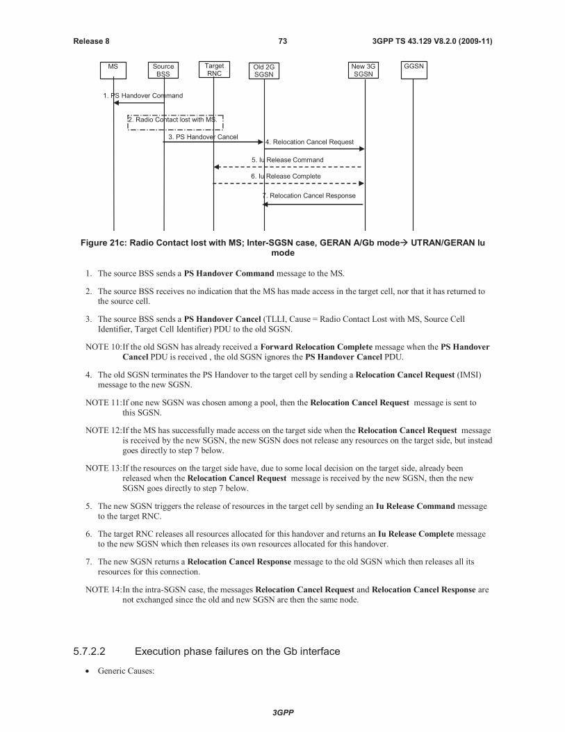
3GPP
3GPP TS 43.129 V8.2.0 (2009-11)73Release 8
TargetRNC
Old 2GSGSN
New 3GSGSN
GGSN
4. Relocation Cancel Request
7. Relocation Cancel Response
3. PS Handover Cancel
2. Radio Contact lost with MS.
SourceBSS
MS
5. Iu Release Command
6. Iu Release Complete
1. PS Handover Command
Figure 21c: Radio Contact lost with MS; Inter-SGSN case, GERAN A/Gb mode UTRAN/GERAN Iumode
1. The source BSS sends a PS Handover Command message to the MS.
2. The source BSS receives no indication that the MS has made access in the target cell, nor that it has returned tothe source cell.
3. The source BSS sends a PS Handover Cancel (TLLI, Cause = Radio Contact Lost with MS, Source Cell
Identifier, Target Cell Identifier) PDU to the old SGSN.
NOTE 10:If the old SGSN has already received a Forward Relocation Complete message when the PS Handover
Cancel PDU is received , the old SGSN ignores the PS Handover Cancel PDU.
4. The old SGSN terminates the PS Handover to the target cell by sending a Relocation Cancel Request (IMSI)message to the new SGSN.
NOTE 11:If one new SGSN was chosen among a pool, then the Relocation Cancel Request message is sent to
this SGSN.
NOTE 12:If the MS has successfully made access on the target side when the Relocation Cancel Request message
is received by the new SGSN, the new SGSN does not release any resources on the target side, but instead
goes directly to step 7 below.
NOTE 13:If the resources on the target side have, due to some local decision on the target side, already been
released when the Relocation Cancel Request message is received by the new SGSN, then the new
SGSN goes directly to step 7 below.
5. The new SGSN triggers the release of resources in the target cell by sending an Iu Release Command message
to the target RNC.
6. The target RNC releases all resources allocated for this handover and returns an Iu Release Complete message
to the new SGSN which then releases its own resources allocated for this handover.
7. The new SGSN returns a Relocation Cancel Response message to the old SGSN which then releases all its
resources for this connection.
NOTE 14:In the intra-SGSN case, the messages Relocation Cancel Request and Relocation Cancel Response are
not exchanged since the old and new SGSN are then the same node.
5.7.2.2 Execution phase failures on the Gb interface
Generic Causes:
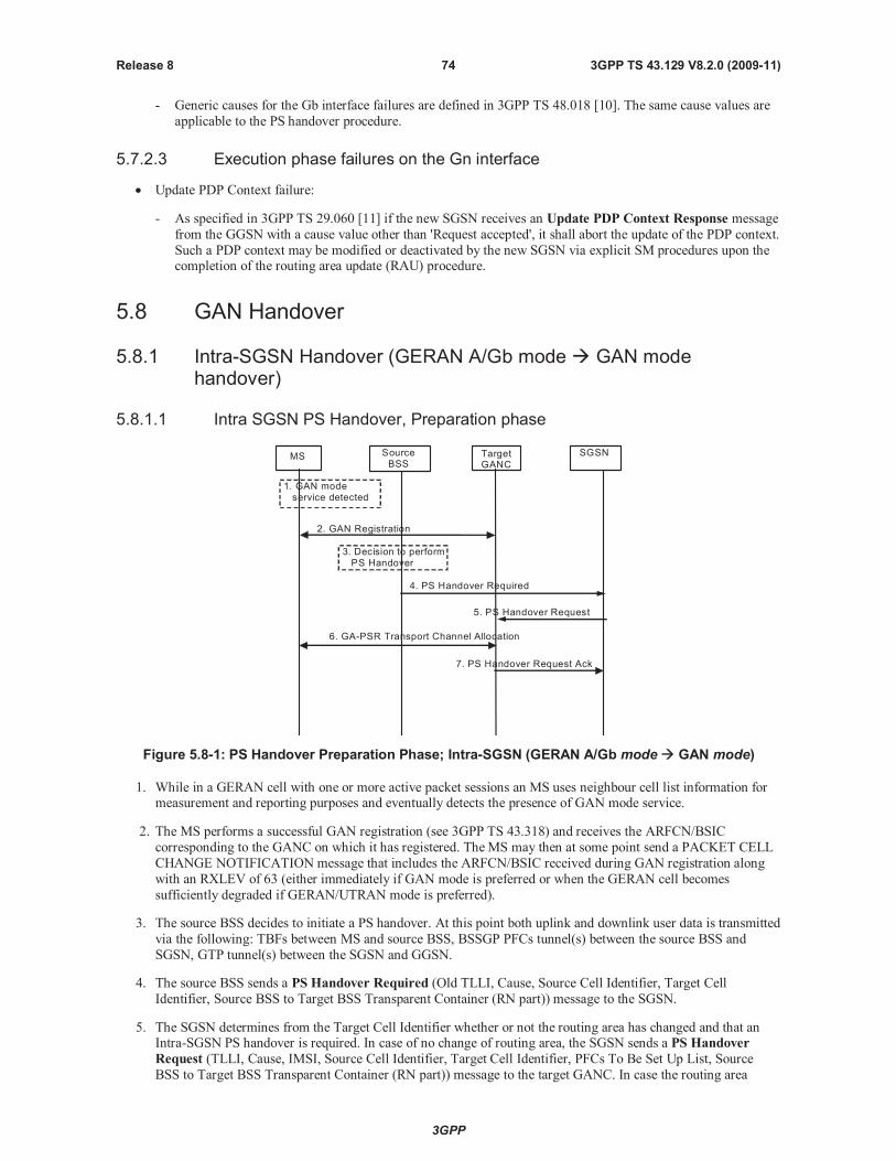
3GPP
3GPP TS 43.129 V8.2.0 (2009-11)74Release 8
- Generic causes for the Gb interface failures are defined in 3GPP TS 48.018 [10]. The same cause values are
applicable to the PS handover procedure.
5.7.2.3 Execution phase failures on the Gn interface
Update PDP Context failure:
- As specified in 3GPP TS 29.060 [11] if the new SGSN receives an Update PDP Context Response message
from the GGSN with a cause value other than 'Request accepted', it shall abort the update of the PDP context.
Such a PDP context may be modified or deactivated by the new SGSN via explicit SM procedures upon thecompletion of the routing area update (RAU) procedure.
5.8 GAN Handover
5.8.1 Intra-SGSN Handover (GERAN A/Gb mode GAN modehandover)
5.8.1.1 Intra SGSN PS Handover, Preparation phase
MS TargetGANC
SourceBSS
SGSN
1. GAN modeservice detected
2. GAN Registration
4. PS Handover Required
5. PS Handover Request
7. PS Handover Request Ack
6. GA-PSR Transport Channel Allocation
3. Decision to performPS Handover
Figure 5.8-1: PS Handover Preparation Phase; Intra-SGSN (GERAN A/Gb mode GAN mode)
1. While in a GERAN cell with one or more active packet sessions an MS uses neighbour cell list information formeasurement and reporting purposes and eventually detects the presence of GAN mode service.
2. The MS performs a successful GAN registration (see 3GPP TS 43.318) and receives the ARFCN/BSIC
corresponding to the GANC on which it has registered. TheMS may then at some point send a PACKET CELL
CHANGE NOTIFICATION message that includes the ARFCN/BSIC received during GAN registration along
with an RXLEV of 63 (either immediately if GAN mode is preferred or when the GERAN cell becomes
sufficiently degraded if GERAN/UTRAN mode is preferred).
3. The source BSS decides to initiate a PS handover. At this point both uplink and downlink user data is transmitted
via the following: TBFs between MS and source BSS, BSSGP PFCs tunnel(s) between the source BSS and
SGSN, GTP tunnel(s) between the SGSN and GGSN.
4. The source BSS sends a PS Handover Required (Old TLLI, Cause, Source Cell Identifier, Target Cell
Identifier, Source BSS to Target BSS Transparent Container (RN part)) message to the SGSN.
5. The SGSN determines from the Target Cell Identifier whether or not the routing area has changed and that anIntra-SGSN PS handover is required. In case of no change of routing area, the SGSN sends a PS Handover
Request (TLLI, Cause, IMSI, Source Cell Identifier, Target Cell Identifier, PFCs To Be Set Up List, Source
BSS to Target BSS Transparent Container (RN part)) message to the target GANC. In case the routing area

3GPP
3GPP TS 43.129 V8.2.0 (2009-11)75Release 8
changes, the SGSN shall assign a new P-TMSI for the MS and derive a local TLLI prior to the sending of the PS
Handover Request message. All PFCs shall be included in this message regardless of whether or not they are
active.
NOTE 1: The BSS PFCs required to be set up are downloaded to the target GANC from the SGSN, i.e. all
information required for PFC creation.
6. Based upon the ABQP for each PFC the target GANCmakes a decision about whether or not to activate a GA-PSR Transport Channel. If a GA-PSR Transport Channel is allocated it is used to support the packet data flow
requirements of all requested PFCs. The details of this decision are implementation specific but could take into
account the current GAN cell loading and the ABQP indicated for each requested PFC. The target GANC
allocates a GA-PSR Transport Channel as described in 3GPP TS 43.318. After allocating the GA-PSR Transport
Channel the target GANC shall prepare the Target BSS to Source BSS Transparent Container for the set up BSS
PFCs.
7. The target GANC sends the PS Handover Request Acknowledge (TLLI, List of Set Up PFCs, Target BSS to
Source BSS Transparent Container (RN part)) message to the SGSN. Upon sending the PS Handover Request
Acknowledge message the target GANC shall be prepared to receive downlink LLC PDUs from the SGSN for
all requested PFCs (i.e. the List of Set Up PFCs in this message shall always match the PFCs To Be Set Up List
included in the corresponding PS Handover Request message since a GA-PSR Transport Channel is allocated
with the intent of supporting all PFCs requested by the SGSN).
When the SGSN receives the PS Handover Request Acknowledgemessage and it decides to proceed with the
handover, the preparation phase is finished and the execution phase will follow.
5.8.1.2 Intra SGSN PS Handover, Execution phase
The execution phase is the same as described for Intra SGSN, GERAN A/Gb mode to GERAN A/Gb mode PS
handover except for the following:
The BSS sends the PS Handover Command message where the RN part does not include any of the optional
information.
After receiving the PS Handover Command message in the source cell the MS determines that the indicated
ARFCN and BSIC match those of the GAN cell that it last registered on and therefore does not perform system
synchronization in the GAN cell. Instead, the MS enables the transmission of uplink LLC PDUs on the
allocated GA-PSR Transport Channel and sends a GA-PSR HANDOVER COMPLETE message to the target
GANC. Note that the reception of downlink LLC PDUs is enabled in the MS upon allocation of the GA-PSR
Transport Channel during the preparation phase.
Upon reception of the GA-PSR HANDOVER COMPLETE message from the MS in the GAN cell the target
GANC sends a PS Handover Complete (TLLI, IMSI, Target Cell Identifier) message to the SGSN.
5.8.2 Intra-SGSN Handover (GAN mode GERAN A/Gb modehandover)
5.8.2.1 Intra SGSN PS Handover, Preparation phase
The preparation phase is the same as described for Intra SGSN, GERAN A/Gb mode to GERAN A/Gb mode PS
handover except for the following:
While in a GAN cell an MS sends theGA-PSR HANDOVER INFORMATIONmessage to the GANC
indicating a list of target GERAN A/Gb mode cells, identified by CGI, in order of preference for PS handover,and includes the received signal strength for each identified GERAN A/Gb mode cell. The MS decision to send
the GA-PSR HANDOVER INFORMATIONmay be based on local measurements in the MS (see 3GPP TS
44.318 [28]). This list is the most recent information available from the GSM RR subsystem. In addition, the
GA-PSR HANDOVER INFORMATIONmessage may include a list of target UTRAN cells ranked in order
of preference for PS handover, and the received signal strength for each identified UTRAN cell.
The source GANC selects a target GERAN A/Gb mode cell and triggers the PS handover preparation phase bysignalling to the SGSN the need for PS handover (i.e. it sends the PS Handover Required message) and
including the target GERAN A/Gb mode cell.
3GPP
3GPP TS 43.129 V8.2.0 (2009-11)76Release 8
When the source GANC decides to trigger a PS handover both uplink and downlink user data is transmitted via
the GA-PSR Transport Channel between MS and source GANC, BSSGP PFCs tunnel(s) between the source
GANC and SGSN, and GTP tunnel(s) between the SGSN and GGSN.
5.8.2.2 Intra SGSN PS Handover, Execution phase
The execution phase is the same as described for Intra SGSN, GERAN A/Gb mode to GERAN A/Gb mode PS
handover except for the following:
The SGSN sends a PS Handover Required Acknowledge (Old TLLI, List of Set Up PFCs, Target BSS toSource BSS Transparent Container (RN part)) message to the source GANC.
Before sending theGA-PSR HANDOVER COMMANDmessage to the MS the source GANC, based on
QoS, may try to empty the downlink GANC buffer for one or more PFCs.
The source GANC interrupts the downlink transmission of LLC PDUs on the GA-PSR Transport Channel and
sends the MS a GA-PSR HANDOVER COMMANDmessage that includes a PS Handover Command (RN
part only) created by the target BSS.
5.8.3 Inter-SGSN Handover (GERAN A/Gb mode GAN modehandover)
5.8.3.1 Inter SGSN PS Handover, Preparation phase
The preparation phase is the same as described for Intra SGSN, GERAN A/Gb mode to GAN mode PS handover except
that Inter-SGSN communications are required and are as described for Inter-SGSN A/Gb mode to A/Gb mode PS
handover.
5.8.3.2 Inter SGSN PS Handover, Execution phase
The execution phase is the same as described for the Intra SGSN PS Handover, Execution phase in sub-clause 5.8.1.2.
5.8.4 Inter-SGSN Handover (GAN mode GERAN A/Gb modehandover)
5.8.4.1 Inter SGSN PS Handover, Preparation phase
The preparation phase is the same as described for Inter SGSN, GERAN A/Gb mode to GERAN A/Gb mode PS
handover except for the following:
While in a GAN cell an MS sends theGA-PSR HANDOVER INFORMATIONmessage to the GANC
indicating a list of target GERAN A/Gb mode cells, identified by CGI, in order of preference for PS handover,
and includes the received signal strength for each identified GERAN A/Gb mode cell. The MS decision to send
the GA-PSR HANDOVER INFORMATIONmessage may be based on local measurements in the MS (see
3GPP TS 44.318 [28]). This list is the most recent information available from the GSM RR subsystem. In
addition, theGA-PSR HANDOVER INFORMATIONmessage may include a list of target UTRAN cells
ranked in order of preference for PS handover, and the received signal strength for each identified UTRAN cell.
The source GANC selects a target GERAN A/Gb mode cell and triggers the PS handover preparation phase by
signalling to the SGSN the need for PS handover (i.e. it sends the PS Handover Required message) and
including the GERAN A/Gb mode target cell.
When the source GANC decides to trigger a PS handover both uplink and downlink user data is transmitted via
the GA-PSR Transport Channel between MS and source GANC, BSSGP PFCs tunnel(s) between the source
GANC and SGSN, GTP tunnel(s) between the SGSN and GGSN.
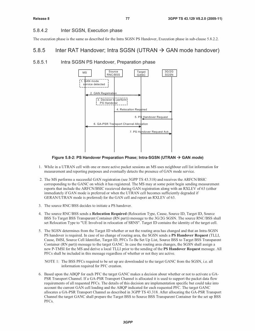
3GPP
3GPP TS 43.129 V8.2.0 (2009-11)77Release 8
5.8.4.2 Inter SGSN, Execution phase
The execution phase is the same as described for the Intra SGSN PS Handover, Execution phase in sub-clause 5.8.2.2.
5.8.5 Inter RAT Handover; Intra SGSN (UTRAN GAN mode handover)
5.8.5.1 Intra SGSN PS Handover, Preparation phase
MS TargetGANC
SourceRNC/BSS
3G/2GSGSN
1. GAN modeservice detected
2. GAN Registration
4. Relocation Required
5. PS Handover Request
7. PS Handover Request Ack
6. GA-PSR Transport Channel Allocation
3. Decision to performPS Handover
Figure 5.8-2: PS Handover Preparation Phase; Intra-SGSN (UTRAN GAN mode)
1. While in a UTRAN cell with one or more active packet sessions an MS uses neighbour cell list information for
measurement and reporting purposes and eventually detects the presence of GAN mode service.
2. The MS performs a successful GAN registration (see 3GPP TS 43.318) and receives the ARFCN/BSIC
corresponding to the GANC on which it has registered. TheMS may at some point begin sending measurement
reports that include the ARFCN/BSIC receieved during GAN registration along with an RXLEV of 63 (eitherimmediately if GAN mode is preferred or when the UTRAN cell becomes sufficiently degraded if
GERAN/UTRAN mode is preferred) for the GAN cell and report an RXLEV of 63.
3. The source RNC/BSS decides to initiate a PS handover.
4. The source RNC/BSS sends a Relocation Required (Relocation Type, Cause, Source ID, Target ID, Source
BSS To Target BSS Transparent Container (RN part)) message to the 3G/2G SGSN. The source RNC/BSS shall
set Relocation Type to "UE Involved in relocation of SRNS". Target ID contains the identity of the target cell.
5. The SGSN determines from the Target ID whether or not the routing area has changed and that an Intra-SGSN
PS handover is required. In case of no change of routing area, the SGSN sends a PS Handover Request (TLLI,
Cause, IMSI, Source Cell Identifier, Target ID, PFCs To Be Set Up List, Source BSS to Target BSS Transparent
Container (RN part)) message to the target GANC. In case the routing area changes, the SGSN shall assign a
new P-TMSI for the MS and derive a local TLLI prior to the sending of the PS Handover Request message. All
PFCs shall be included in this message regardless of whether or not they are active.
NOTE 1: The BSS PFCs required to be set up are downloaded to the target GANC from the SGSN, i.e. all
information required for PFC creation.
6. Based upon the ABQP for each PFC the target GANCmakes a decision about whether or not to activate a GA-
PSR Transport Channel. If a GA-PSR Transport Channel is allocated it is used to support the packet data flow
requirements of all requested PFCs. The details of this decision are implementation specific but could take intoaccount the current GAN cell loading and the ABQP indicated for each requested PFC. The target GANC
allocates a GA-PSR Transport Channel as described in 3GPP TS 43.318. After allocating the GA-PSR Transport
Channel the target GANC shall prepare the Target BSS to Source BSS Transparent Container for the set up BSS
PFCs.
3GPP
3GPP TS 43.129 V8.2.0 (2009-11)78Release 8
7. The target GANC sends the PS Handover Request Acknowledge (TLLI, List of Set Up PFCs, Target BSS to
Source BSS Transparent Container (RN part)) message to the SGSN. Upon sending the PS Handover Request
Acknowledge message the target GANC shall be prepared to receive downlink LLC PDUs from the SGSN for
all requested PFCs (i.e. the List of Set Up PFCs in this message shall always match the PFCs To Be Set Up List
included in the corresponding PS Handover Request message since a GA-PSR Transport Channel is allocated
with the intent of supporting all PFCs requested by the SGSN).
When the SGSN receives the PS Handover Request Acknowledgemessage and it decides to proceed with the
handover, the preparation phase is finished and the execution phase will follow.
5.8.5.2 Intra SGSN PS Handover, Execution phase
The execution phase is the same as described for Intra SGSN, UTRAN/GERAN Iu mode to GERAN A/Gb mode PS
handover except for the following:
The RNC sends theHandover from UTRAN Command message to the MS where each message includes a
PS Handover Command message where the RN part does not include any of the optional information.
After receiving theHandover from UTRAN Command message in the source cell the MS determines that the
indicated ARFCN and BSIC match those of the GAN cell that it last registered on and therefore does not
perform system synchronization in the GAN cell. Instead, the MS enables the transmission of uplink LLC
PDUs on the allocated GA-PSR Transport Channel and sends a GA-PSR HANDOVER COMPLETE message
to the target GANC. Note that the reception of downlink LLC PDUs is enabled in the MS upon allocation of the
GA-PSR Transport Channel during the preparation phase.
Upon reception of the GA-PSR HANDOVER COMPLETE message from the MS in the GAN cell the target
GANC sends a PS Handover Complete (TLLI, IMSI, Target Cell Identifier) message to the SGSN.
5.8.6 Inter RAT Handover; Intra SGSN (GAN mode UTRAN handover)
5.8.6.1 Intra SGSN PS Handover, Preparation phase
The preparation phase is the same as described for Intra SGSN, GERAN A/Gb mode to UTRAN/GERAN Iu mode PS
handover except for the following:
While in a GAN cell an MS sends the GA-PSR HANDOVER INFORMATION message to the GANC
indicating a list of target UTRAN cells, identified by a combination of LAI and 3G Cell Identity/CGI, in order
of preference for PS handover, and includes the received signal strength for each identified UTRAN cell. The
MS decision to send the GA-PSR HANDOVER INFORMATION may be based on local measurements in the
MS (see 3GPP TS 44.318 [28]). This list is the most recent information available from the UTRAN RRC/GSM
RR subsystem. In addition, the GA-PSR HANDOVER INFORMATION message may include a list of target
GERAN A/Gb mode cells ranked in order of preference for PS handover, and the received signal strength for
each identified GERAN A/Gb mode cell.
The source GANC selects a target UTRAN cell and triggers the PS handover preparation phase by signalling to
the SGSN the need for PS handover (i.e. it sends the PS Handover Required message) and including the target
UTRANcell.
When the source GANC decides to trigger a PS handover both uplink and downlink user data is transmitted via
the GA-PSR Transport Channel between MS and source GANC, BSSGP PFCs tunnel(s) between the source
GANC and SGSN, GTP tunnel(s) between the SGSN and GGSN.
5.8.6.2 Intra SGSN, Execution phase
The execution phase is the same as described for Intra SGSN, GERAN A/Gb mode to UTRAN/GERAN Iu mode PS
handover except for the following:
The SGSN sends a PS Handover Required Acknowledge (Old TLLI, List of Set Up PFCs, Target BSS to
Source BSS Transparent Container (RN part)) message to the source GANC.
Before sending theGA-PSR HANDOVER COMMANDmessage to the MS the source GANC, based on
QoS, may try to empty the downlink GANC buffer for one or more PFCs.
3GPP
3GPP TS 43.129 V8.2.0 (2009-11)79Release 8
The source GANC interrupts the downlink transmission of LLC PDUs on the GA-PSR Transport Channel and
sends the MS a GA-PSR HANDOVER COMMANDmessage that includes a Handover to UTRAN
Command message (as specified in 3GPP TS 25.331 [17]) created by the target RNC.
5.8.7 Inter RAT Handover; Inter SGSN (UTRAN GAN mode handover)
5.8.7.1 Inter SGSN PS Handover, Preparation phase
The preparation phase is the same as described for Intra SGSN, UTRAN to GAN mode PS handover except that Inter-
SGSN communications are required and are as described for Inter-SGSN UTRAN to A/Gb mode PS handover.
5.8.7.2 Inter SGSN PS Handover, Execution phase
The execution phase is the same as described for the Intra SGSN PS Handover, Execution phase in sub-clause 5.8.5.2.
5.8.8 Inter RAT Handover; Inter SGSN (GAN mode UTRAN handover)
5.8.8.1 Inter SGSN PS Handover, Preparation phase
The preparation phase is the same as described for Inter SGSN, GERAN A/Gb mode to UTRAN/GERAN Iu mode PS
handover except for the following:
While in a GAN cell an MS sends theGA-PSR HANDOVER INFORMATIONmessage to the GANC
indicating a list of target UTRAN cells, identified by a combination of LAI and 3G Cell Identity/CGI, in order
of preference for PS handover, and includes the received signal strength for each identified UTRAN cell. The
MS decision to send theGA-PSR HANDOVER INFORMATIONmessage may be based on local
measurements in the MS (see 3GPP TS 44.318 [28]). This list is the most recent information available from the
UTRAN RRC/GSM RR subsystem. In addition, theGA-PSR HANDOVER INFORMATIONmessage may
include a list of target GERAN A/Gb mode cells ranked in order of preference for PS handover, and the
received signal strength for each identified GERAN A/Gb mode cell.
The source GANC selects a target UTRAN cell and triggers the PS handover preparation phase by signalling to
the SGSN the need for PS handover (i.e. it sends the PS Handover Required message) and including the target
UTRAN cell.
When the source GANC decides to trigger a PS handover both uplink and downlink user data is transmitted via
the GA-PSR Transport Channel between MS and source GANC, BSSGP PFCs tunnel(s) between the source
GANC and SGSN, and GTP tunnel(s) between the SGSN and GGSN.
5.8.8.2 Inter SGSN PS Handover, Execution phase
The execution phase is the same as described for the Intra SGSN, Execution phase in sub-clause 5.8.6.2.
6 Radio interface Signalling
6.1 PS Handover Signalling (Um)
6.1.1 General
PS Handover signalling includes the set of all air interface messages (Um signalling for A/Gb mode, Up signalling for
GAN mode and Uu signalling for Iu mode) sent to or from the MS in the source and target cells during the PS handover
procedure.
3GPP
3GPP TS 43.129 V8.2.0 (2009-11)80Release 8
6.1.2 Overview of PS Handover messages
6.1.2.1 GERAN A/Gb mode/GAN mode to GERAN A/Gb mode PS Handover
When performing an inter-SGSN PS Handover from GERAN A/Gb mode/GAN mode to GERAN A/Gb mode thefollowing information is sent over the Um and Up interfaces.
PS Handover Command message (for PS handover from GERAN A/Gb mode) or a GA-PSR HANDOVER
COMMANDmessage including a PS Handover Command message (for PS handover from GAN mode) -
sent to the MS in the source cell and includes the following:
- optionally, the NAS container for PS HO
- Indication of the radio resources for uplink and downlink TBFs to be used in the target cell for each PFCreceiving PS handover treatment (i.e. the reverse path container created by target BSS/RNC).
- Indication of a PS handover reference number to be used when the MS arrives in the target cell.
PS Handover Accessmessage - the MS sends 4 handover access bursts in the target cell using an uplink TBF
provided by the PS Handover Command. If multiple uplink TBFs are provided by the PS Handover Command
message the MS sends access bursts using just one of these TBFs (i.e. at minimum one uplink TBF must be
provided in the PS Handover Command message). The handover reference number is included within each
access burst. This message is always sent for the case of non-synchronised handover and may still be sent for
the case of synchronised or pre-synchronised handovers (determined by the target BSS during the PS handover
preparation phase) to allow the target BSS to verify the accessing MS.
Packet Physical Information message - sent by the target BSS to the MS in the target cell in response to the
PS Handover Accessmessage for the case of unsynchronised cells. Whether or not this message is sent in case
of synchronised cells is indicated by the PS Handover command message (see 3GPP TS 44.018 [25]). It is
sent using the downlink PACCH associated with the uplink TBF used to send the access bursts and provides the
MS with physical layer information (i.e. Timing Advance). The time alignment information received in this
message applies to all uplink TBFs allocated to the MS in the PS Handover Command message. The target
BSS only sends this information if it receives the expected handover reference number in a PS Handover
Accessmessage.
Uplink RLC Data Blocks - sent on uplink TBFs allocated by the PS Handover Command message after the
MS receives Packet Physical Information message as follows:
- For inter-SGSN PS handover the MS, prior to sending any uplink user plane payload for any PFC, shall send
an XID Response message .
Downlink RLC Data Blocks - sent on downlink TBFs allocated by the PS Handover Command message as
follows:
- For inter-SGSN PS handover for a given PFC the new SGSN may begin downlink N-PDU transmissions for
that PFC prior to receiving a PS Handover Complete message (i.e. blind transmission may be used) or it
may wait for a PS Handover Complete message before beginning downlink N-PDU transmissions for that
PFC.
GA-PSR HANDOVER INFORMATIONmessage (for PS handover from GAN mode) – sent from the MS to
the GANC to provide a list of target GERAN A/Gb mode cells, identified by CGI, in order of preference for PS
handover, and includes the received signal strength for each identified GERAN A/Gb mode cell.
GA-PSR UPLINK QUALITY INDICATIONmessage (for PS handover from GAN mode) – sent from the
GANC to the MS to provide it with PS service related information as perceived by the GANC which may result
in the MS triggering the PS handover procedure (i.e. sending a GA-PSR HANDOVER INFORMATION
message).
6.1.2.2 UTRAN/GERAN Iu mode to GERAN A/Gb mode/GAN mode PS Handover
When performing a PS Handover from UTRAN/GERAN Iu mode to GERAN A/Gb mode or from UTRAN to GAN
mode the following the following information is sent over the Uu, Up and Um interfaces:
3GPP
3GPP TS 43.129 V8.2.0 (2009-11)81Release 8
RRC Message - sent to the MS in the source cell and includes the same information described for the PS
Handover Command in clause 6.1.2.1.
For PS handover from UTRAN to GERAN A/Gb mode/GAN mode the Handover from UTRAN Command
(3GPP TS 25.331 [17]) message is used in CELL_DCH and CELL_FACH state when only PS RABs are
established.
For PS handover from GERAN Iu mode to GERAN A/Gb mode the HANDOVER FROM GERAN IUCOMMAND message is used in RRC-Cell_Dedicated (MAC Dedicated or MAC DTM state) or RRC-
Cell_Shared state when only PS RABs are established.
PS Handover Accessmessage (for PS handover to GERAN A/Gb mode) - sent as described in clause 6.1.2.1.
Packet Physical Information message (for PS handover to GERAN A/Gb mode) - sent as described in clause
6.1.2.1.
Uplink RLC Data Blocks (for PS handover to GERAN A/Gb mode) - sent as described in clause 6.1.2.1.
Downlink RLC Data Blocks (for PS handover to GERAN A/Gb mode) - sent as described in clause 6.1.2.1.
The target BSS/GANC may begin downlink LLC PDU transmissions prior to confirming the successful
completion of the PS handover procedure (i.e. blind transmission may be used) or it may wait for an uplink RLC
data block (target BSS) or a GA-PSR HANDOVER COMPLETE message (GANC) before beginning downlink
N-PDU transmissions.
GA-PSR ACTIVATE UTC REQ message (for PS handover from UTRAN to GAN mode) – sent to the MS
from the target GANC to activate the transport channel to be used in the GAN cell.
GA-PSR ACTIVATE UTC ACK message (for PS handover from UTRAN to GAN mode) – sent from the MS
to the target GANC to confirm allocation of the transport channel to be used in the GAN cell.
GA-PSR HANDOVER COMPLETE message (for PS handover from UTRAN to GAN mode) – sent from the
MS to the target GANC to indicate handover completion.
6.1.2.3 GERAN A/Gb mode to GERAN Iu mode PS Handover
When performing a PS Handover from GERAN A/Gb mode to GERAN Iu mode the following information is sent over
the Uu and Um interfaces:
PS Handover Command message - sent to the MS in the source cell and includes the following:
- System broadcast information applicable to the target cell.
- Indication of the radio resources for uplink and downlink TBFs to be used in the target cell for each RABreceiving PS handover treatment (i.e. the reverse path container created by target BSS). Note that the MS will
map the N-SAPI associated with each of its active PDP Contexts directly to a RABid (i.e. N-SAPI = RABid).
- Indication of a PS handover reference number to be used when the MS arrives in the target cell.
PS Handover Accessmessage - sent as described in clause 6.1.2.1.
Packet Physical Information message - sent as described in clause 6.1.2.1.
RRC message (e.g. Physical Channel Reconfiguration Complete) - content is GERAN Iu mode specific.
Uplink RLC Data Blocks - sent on uplink TBFs allocated by the PS Handover Command message after the MS
receives Physical Layer Information (content is GERAN Iu mode specific).
Downlink RLC Data Blocks - sent on downlink TBFs allocated by the PS Handover Command message (content
is GERAN Iu mode specific).
3GPP
3GPP TS 43.129 V8.2.0 (2009-11)82Release 8
6.1.2.4 GERAN A/Gb mode/GAN mode to UTRAN mode PS Handover
When performing a PS Handover from GERAN A/Gb mode/GAN mode to UTRAN mode the following information is
sent over the Uu, Up and Um interfaces:
PS Handover Command message (for PS handover from GERAN A/Gb mode) or GA-PSR HANDOVER
COMMANDmessage (for PS handover from GAN mode) - sent to the MS in the source cell. It includes the
reverse path container created by the target RNC that consists of the RRC message (i.e. the Handover to UTRAN
Command) required to perform PS handover to UTRAN.
MS Detected by Target RNC - exact procedure and information transfer is UTRAN specific.
RRC message (e.g. Physical Channel Reconfiguration Complete) - information content is UTRAN specific.
GA-PSR HANDOVER INFORMATIONmessage (for PS handover from GAN mode) – sent from the MS to
the GANC to provide a list of target UTRAN cells, identified by a combination of LAI and 3G Cell Identity, in
order of preference for PS handover, and includes the received signal strength for each identified UTRAN cell.
GA-PSR UPLINK QUALITY INDICATIONmessage (for PS handover from GAN mode) – sent from the
GANC to the MS to provide it with PS service related information as perceived by the GANC which may result
in the MS triggering the PS handover procedure (i.e. sending a GA-PSR HANDOVER INFORMATION
message).
6.1.2.5 GERAN A/Gb mode to GAN mode PS Handover
When performing an inter-SGSN PS Handover from GERAN A/Gb mode to GAN mode the following information is
sent over the Um and Up interfaces.
PS Handover Command message - sent to the MS in the source cell and includes the following:
- optionally, the NAS container for PS HO.
- RN information which consists only of the mandatory fields within the PS Handover Radio Resources IE
carried within the PS Handover Command message.
The target GANC may begin downlink LLC PDU transmissions prior to confirming the successful completion of
the PS handover procedure (i.e. blind transmission may be used) or it may wait for a GA-PSR HANDOVER
COMPLETE message before beginning downlink N-PDU transmissions.
GA-PSR ACTIVATE UTC REQ message – sent to the MS from the target GANC to activate the transport
channel to be used in the GAN cell.
GA-PSR ACTIVATE UTC ACK message – sent from the MS to the target GANC to confirm allocation of the
transport channel to be used in the GAN cell.
GA-PSR HANDOVER COMPLETE message – sent from the MS to the target GANC to indicate handover
completion.
6.1.2.6 GERAN A/Gb mode to E-UTRAN PS Handover
When performing a PS Handover from GERAN A/Gb mode to E-UTRAN the following information is sent over the
radio interface:
- PS Handover Command message (for PS handover from GERAN A/Gb mode) to the MS in the source cell (on
the Um interface). It includes the reverse path container created by the target eNB that consists of the RRCmessage (i.e. the RRCConnectionReconfigurationmessage) required to perform PS handover to E-UTRAN.
- MS Detected by Target eNB- the exact procedure and information transfer on the Uu interface is E-UTRAN
specific 3GPP TS36.300 [30], 3GPP TS36.331 [31].
- RRC message on the Uu interface - information content is E-UTRAN specific TS36.331 [31].
3GPP
3GPP TS 43.129 V8.2.0 (2009-11)83Release 8
6.1.2.7 E-UTRAN to GERAN A/Gb mode PS Handover
When performing a PS Handover from E-UTRAN to GERAN A/Gb mode the following information is sent over the
radio interface:
- RRC Message - sent to the MS in the source cell (on the Uu interface). It includes the same information
described for the PS Handover Command in sub-clause 6.1.2.1.
- TheMobilityFromEUTRACommand (3GPP TS 36.331 [31]) message is sent to the UE (on the Uu interface).
- PS Handover Accessmessage (for PS handover to GERAN A/Gb mode) – sent on the Um interface as
described in sub-clause 6.1.2.1.
- Packet Physical Information message (for PS handover to GERAN A/Gb mode) – sent on the Um interface as
described in sub-clause 6.1.2.1.
- Uplink RLC Data Blocks (for PS handover to GERAN A/Gb mode) - sent on the Um interface as described in
sub-clause 6.1.2.1.
- Downlink RLC Data Blocks (for PS handover to GERAN A/Gb mode) - sent on the Um interface as described in
sub-clause 6.1.2.1.
- The target BSS may begin downlink LLC PDU transmissions prior to confirming the successful completion of
the PS handover procedure (i.e. blind transmission may be used) or it may wait for an uplink RLC data block
(target BSS).
6.1.3 RLC/MAC segmentation
RLC/MAC segmentation is a feature that provides an additional mechanism for sending control plane messages from
the BSS to the MS. This feature can only be used after contention resolution is completed in the BSS and the BSS has to
send an RLC/MAC control message that is from 3 to 9 radio blocks long.
6.1.4 Inter RAT/mode PS Handover to GERAN A/Gb
Void.
6.1.5 Inter RAT/mode PS Handover from GERAN A/Gb
Void.
6.2 Mechanisms for Initial Access in the Target Cell
6.2.1 General
This clause describes two possible approaches to the MS making access in the target cell. Both basic approaches assume
that a handover procedure similar to that for the CS domain (Handover Access followed by Physical Informationmessages) takes place.
The effect of synchronised networks is examined for both approaches where the exchange of Handover Access and
Physical Information is not required as the TA can be derived in advance.
The main assumptions applicable to the call flows are:
USFs are required to schedule uplink data blocks.
All identifiers and resources are known by the MS and target BSS before the MS makes the initial access in the
target cell.
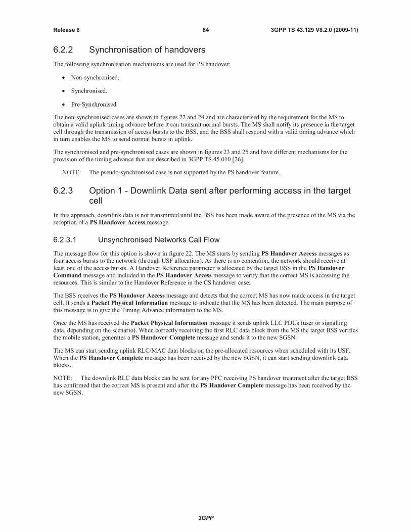
3GPP
3GPP TS 43.129 V8.2.0 (2009-11)84Release 8
6.2.2 Synchronisation of handovers
The following synchronisation mechanisms are used for PS handover:
Non-synchronised.
Synchronised.
Pre-Synchronised.
The non-synchronised cases are shown in figures 22 and 24 and are characterised by the requirement for the MS to
obtain a valid uplink timing advance before it can transmit normal bursts. The MS shall notify its presence in the target
cell through the transmission of access bursts to the BSS, and the BSS shall respond with a valid timing advance which
in turn enables the MS to send normal bursts in uplink.
The synchronised and pre-synchronised cases are shown in figures 23 and 25 and have different mechanisms for the
provision of the timing advance that are described in 3GPP TS 45.010 [26].
NOTE: The pseudo-synchronised case is not supported by the PS handover feature.
6.2.3 Option 1 - Downlink Data sent after performing access in the targetcell
In this approach, downlink data is not transmitted until the BSS has been made aware of the presence of the MS via the
reception of a PS Handover Accessmessage.
6.2.3.1 Unsynchronised Networks Call Flow
The message flow for this option is shown in figure 22. The MS starts by sending PS Handover Access messages as
four access bursts to the network (through USF allocation). As there is no contention, the network should receive at
least one of the access bursts. A Handover Reference parameter is allocated by the target BSS in the PS Handover
Command message and included in the PS Handover Access message to verify that the correct MS is accessing the
resources. This is similar to the Handover Reference in the CS handover case.
The BSS receives the PS Handover Accessmessage and detects that the correct MS has now made access in the target
cell. It sends a Packet Physical Information message to indicate that the MS has been detected. The main purpose of
this message is to give the Timing Advance information to the MS.
Once the MS has received the Packet Physical Information message it sends uplink LLC PDUs (user or signalling
data, depending on the scenario). When correctly receiving the first RLC data block from the MS the target BSS verifies
the mobile station, generates a PS Handover Complete message and sends it to the new SGSN.
The MS can start sending uplink RLC/MAC data blocks on the pre-allocated resources when scheduled with its USF.
When the PS Handover Complete message has been received by the new SGSN, it can start sending downlink datablocks.
NOTE: The downlink RLC data blocks can be sent for any PFC receiving PS handover treatment after the target BSS
has confirmed that the correct MS is present and after the PS Handover Complete message has been received by the
new SGSN.
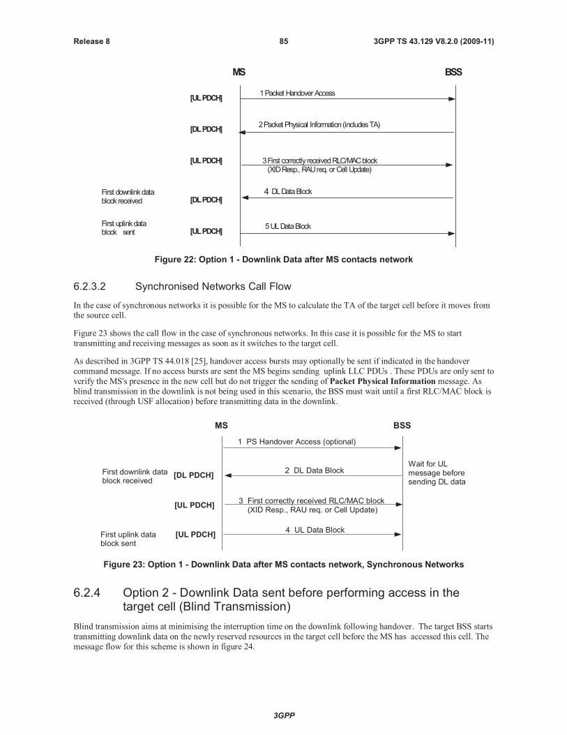
3GPP
3GPP TS 43.129 V8.2.0 (2009-11)85Release 8
MS BSS
1Packet HandoverAccess[ULPDCH]
[DLPDCH]2Packet Physical Information(includesTA)
5ULDataBlock[ULPDCH]
[DLPDCH]4 DLDataBlock
3First correctly receivedRLC/MACblock(XIDResp., RAUreq. orCell Update)
[ULPDCH]
First uplinkdatablock sent
First downlinkdatablock received
Figure 22: Option 1 - Downlink Data after MS contacts network
6.2.3.2 Synchronised Networks Call Flow
In the case of synchronous networks it is possible for the MS to calculate the TA of the target cell before it moves fromthe source cell.
Figure 23 shows the call flow in the case of synchronous networks. In this case it is possible for the MS to start
transmitting and receiving messages as soon as it switches to the target cell.
As described in 3GPP TS 44.018 [25], handover access bursts may optionally be sent if indicated in the handover
command message. If no access bursts are sent the MS begins sending uplink LLC PDUs . These PDUs are only sent to
verify the MS's presence in the new cell but do not trigger the sending of Packet Physical Information message. As
blind transmission in the downlink is not being used in this scenario, the BSS must wait until a first RLC/MAC block is
received (through USF allocation) before transmitting data in the downlink.
MS BSS
3 First correctly received RLC/MAC block(XID Resp., RAU req. or Cell Update)
[UL PDCH]
4 UL Data Block[UL PDCH]
2 DL Data Block[DL PDCH]
Wait for ULmessage beforesending DL data
First downlink datablock received
First uplink datablock sent
1 PS Handover Access (optional)
Figure 23: Option 1 - Downlink Data after MS contacts network, Synchronous Networks
6.2.4 Option 2 - Downlink Data sent before performing access in thetarget cell (Blind Transmission)
Blind transmission aims at minimising the interruption time on the downlink following handover. The target BSS starts
transmitting downlink data on the newly reserved resources in the target cell before the MS has accessed this cell. The
message flow for this scheme is shown in figure 24.
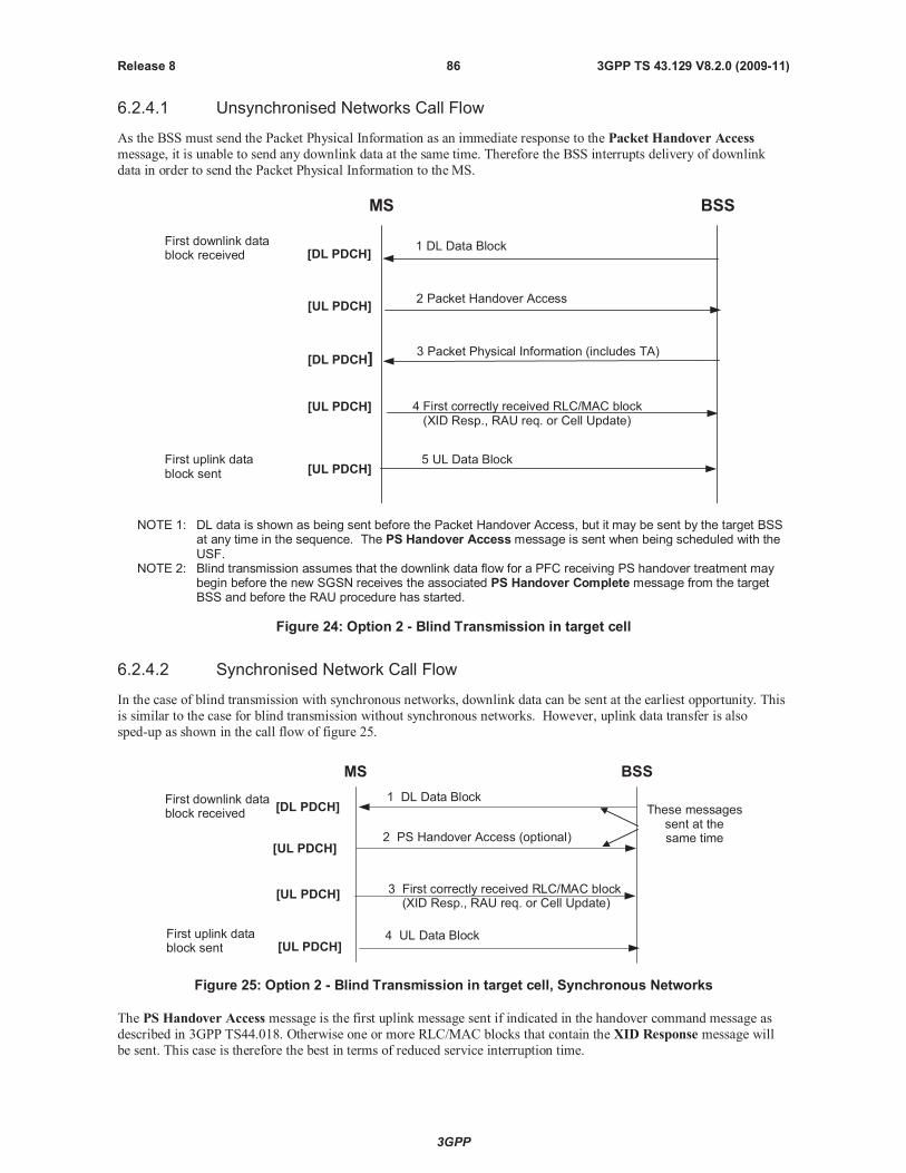
3GPP
3GPP TS 43.129 V8.2.0 (2009-11)86Release 8
6.2.4.1 Unsynchronised Networks Call Flow
As the BSS must send the Packet Physical Information as an immediate response to the Packet Handover Access
message, it is unable to send any downlink data at the same time. Therefore the BSS interrupts delivery of downlink
data in order to send the Packet Physical Information to the MS.
MS BSS
2 Packet Handover Access[UL PDCH]
[DL PDCH]3 Packet Physical Information (includes TA)
1 DL Data Block[DL PDCH]
First downlink datablock received
[UL PDCH]5 UL Data Block
4 First correctly received RLC/MAC block(XID Resp., RAU req. or Cell Update)
[UL PDCH]
First uplink datablock sent
NOTE 1: DL data is shown as being sent before the Packet Handover Access, but it may be sent by the target BSSat any time in the sequence. The PS Handover Accessmessage is sent when being scheduled with theUSF.
NOTE 2: Blind transmission assumes that the downlink data flow for a PFC receiving PS handover treatment maybegin before the new SGSN receives the associated PS Handover Complete message from the targetBSS and before the RAU procedure has started.
Figure 24: Option 2 - Blind Transmission in target cell
6.2.4.2 Synchronised Network Call Flow
In the case of blind transmission with synchronous networks, downlink data can be sent at the earliest opportunity. This
is similar to the case for blind transmission without synchronous networks. However, uplink data transfer is also
sped-up as shown in the call flow of figure 25.
MS BSS
3 First correctly received RLC/MAC block(XID Resp., RAU req. or Cell Update)
1 DL Data Block
[UL PDCH]
[UL PDCH]
These messagessent at thesame time
First downlink datablock received
First uplink datablock sent
4 UL Data Block
2 PS Handover Access (optional)[UL PDCH]
[DL PDCH]
Figure 25: Option 2 - Blind Transmission in target cell, Synchronous Networks
The PS Handover Access message is the first uplink message sent if indicated in the handover command message as
described in 3GPP TS44.018. Otherwise one or more RLC/MAC blocks that contain the XID Response message will
be sent. This case is therefore the best in terms of reduced service interruption time.
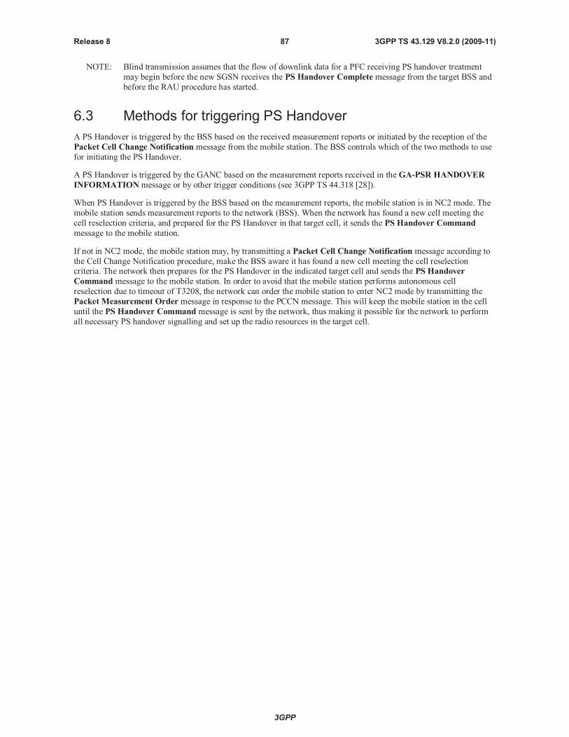
3GPP
3GPP TS 43.129 V8.2.0 (2009-11)87Release 8
NOTE: Blind transmission assumes that the flow of downlink data for a PFC receiving PS handover treatment
may begin before the new SGSN receives the PS Handover Complete message from the target BSS and
before the RAU procedure has started.
6.3 Methods for triggering PS Handover
A PS Handover is triggered by the BSS based on the received measurement reports or initiated by the reception of the
Packet Cell Change Notification message from the mobile station. The BSS controls which of the two methods to use
for initiating the PS Handover.
A PS Handover is triggered by the GANC based on the measurement reports received in theGA-PSR HANDOVER
INFORMATIONmessage or by other trigger conditions (see 3GPP TS 44.318 [28]).
When PS Handover is triggered by the BSS based on the measurement reports, the mobile station is in NC2 mode. The
mobile station sends measurement reports to the network (BSS). When the network has found a new cell meeting the
cell reselection criteria, and prepared for the PS Handover in that target cell, it sends the PS Handover Command
message to the mobile station.
If not in NC2 mode, the mobile station may, by transmitting a Packet Cell Change Notification message according to
the Cell Change Notification procedure, make the BSS aware it has found a new cell meeting the cell reselectioncriteria. The network then prepares for the PS Handover in the indicated target cell and sends the PS Handover
Command message to the mobile station. In order to avoid that the mobile station performs autonomous cell
reselection due to timeout of T3208, the network can order the mobile station to enter NC2 mode by transmitting the
Packet Measurement Order message in response to the PCCN message. This will keep the mobile station in the cell
until the PS Handover Command message is sent by the network, thus making it possible for the network to perform
all necessary PS handover signalling and set up the radio resources in the target cell.
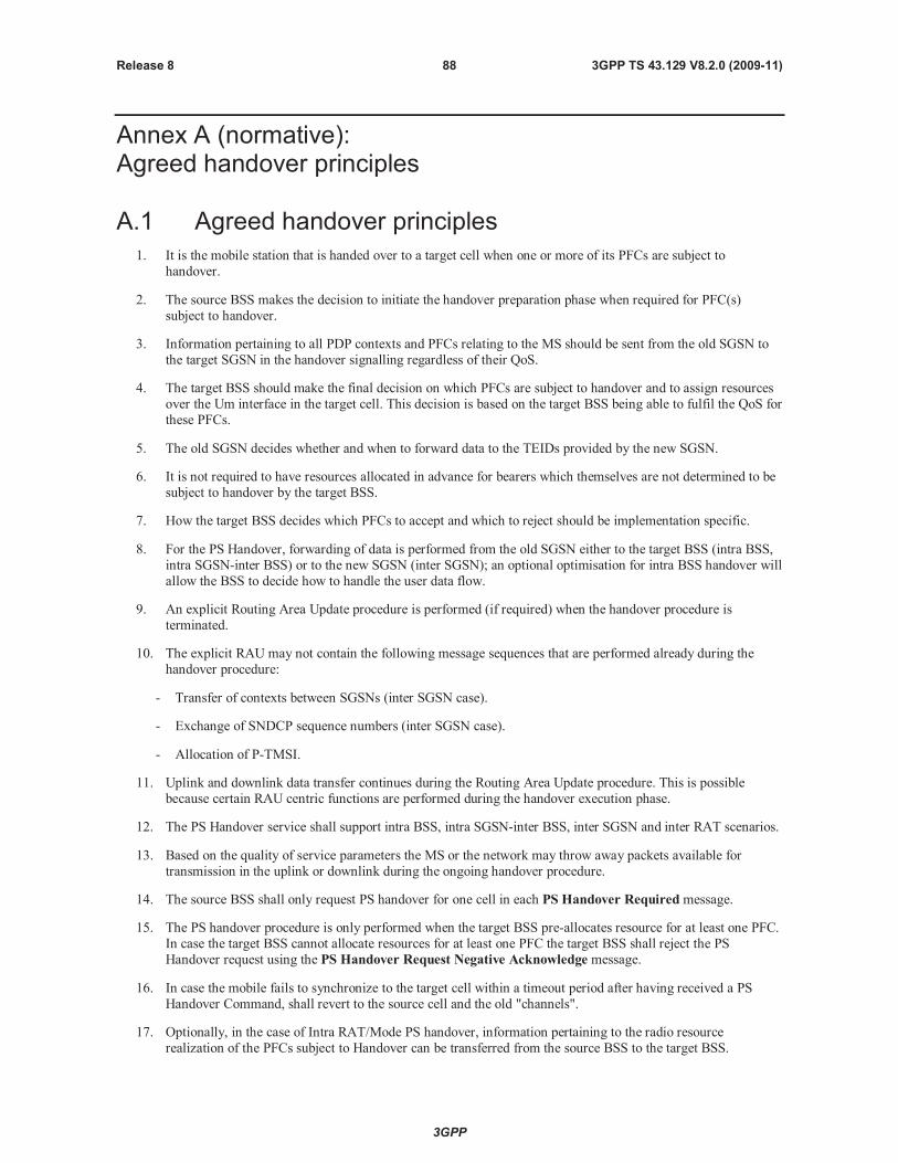
3GPP
3GPP TS 43.129 V8.2.0 (2009-11)88Release 8
Annex A (normative):Agreed handover principles
A.1 Agreed handover principles
1. It is the mobile station that is handed over to a target cell when one or more of its PFCs are subject to
handover.
2. The source BSS makes the decision to initiate the handover preparation phase when required for PFC(s)
subject to handover.
3. Information pertaining to all PDP contexts and PFCs relating to the MS should be sent from the old SGSN to
the target SGSN in the handover signalling regardless of their QoS.
4. The target BSS should make the final decision on which PFCs are subject to handover and to assign resources
over the Um interface in the target cell. This decision is based on the target BSS being able to fulfil the QoS for
these PFCs.
5. The old SGSN decides whether and when to forward data to the TEIDs provided by the new SGSN.
6. It is not required to have resources allocated in advance for bearers which themselves are not determined to be
subject to handover by the target BSS.
7. How the target BSS decides which PFCs to accept and which to reject should be implementation specific.
8. For the PS Handover, forwarding of data is performed from the old SGSN either to the target BSS (intra BSS,
intra SGSN-inter BSS) or to the new SGSN (inter SGSN); an optional optimisation for intra BSS handover will
allow the BSS to decide how to handle the user data flow.
9. An explicit Routing Area Update procedure is performed (if required) when the handover procedure is
terminated.
10. The explicit RAU may not contain the following message sequences that are performed already during the
handover procedure:
- Transfer of contexts between SGSNs (inter SGSN case).
- Exchange of SNDCP sequence numbers (inter SGSN case).
- Allocation of P-TMSI.
11. Uplink and downlink data transfer continues during the Routing Area Update procedure. This is possible
because certain RAU centric functions are performed during the handover execution phase.
12. The PS Handover service shall support intra BSS, intra SGSN-inter BSS, inter SGSN and inter RAT scenarios.
13. Based on the quality of service parameters the MS or the network may throw away packets available for
transmission in the uplink or downlink during the ongoing handover procedure.
14. The source BSS shall only request PS handover for one cell in each PS Handover Requiredmessage.
15. The PS handover procedure is only performed when the target BSS pre-allocates resource for at least one PFC.
In case the target BSS cannot allocate resources for at least one PFC the target BSS shall reject the PS
Handover request using the PS Handover Request Negative Acknowledge message.
16. In case the mobile fails to synchronize to the target cell within a timeout period after having received a PS
Handover Command, shall revert to the source cell and the old "channels".
17. Optionally, in the case of Intra RAT/Mode PS handover, information pertaining to the radio resource
realization of the PFCs subject to Handover can be transferred from the source BSS to the target BSS.
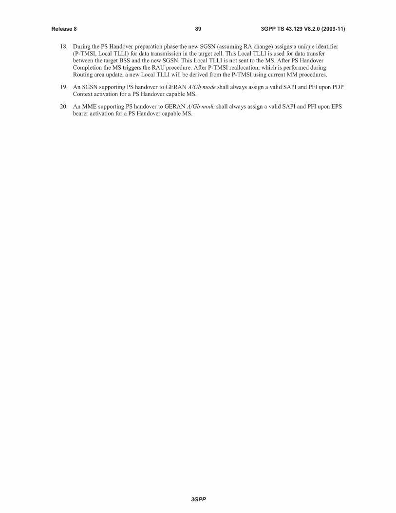
3GPP
3GPP TS 43.129 V8.2.0 (2009-11)89Release 8
18. During the PS Handover preparation phase the new SGSN (assuming RA change) assigns a unique identifier
(P-TMSI, Local TLLI) for data transmission in the target cell. This Local TLLI is used for data transfer
between the target BSS and the new SGSN. This Local TLLI is not sent to the MS. After PS Handover
Completion the MS triggers the RAU procedure. After P-TMSI reallocation, which is performed during
Routing area update, a new Local TLLI will be derived from the P-TMSI using current MM procedures.
19. An SGSN supporting PS handover to GERAN A/Gb mode shall always assign a valid SAPI and PFI upon PDP
Context activation for a PS Handover capable MS.
20. An MME supporting PS handover to GERAN A/Gb mode shall always assign a valid SAPI and PFI upon EPS
bearer activation for a PS Handover capable MS.
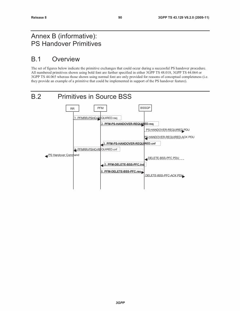
3GPP
3GPP TS 43.129 V8.2.0 (2009-11)90Release 8
Annex B (informative):PS Handover Primitives
B.1 Overview
The set of figures below indicate the primitive exchanges that could occur during a successful PS handover procedure.
All numbered primitives shown using bold font are further specified in either 3GPP TS 48.018, 3GPP TS 44.064 or
3GPP TS 44.065 whereas those shown using normal font are only provided for reasons of conceptual completeness (i.e.
they provide an example of a primitive that could be implemented in support of the PS handover feature).
B.2 Primitives in Source BSS
RR PFM BSSGP
2. PFM-PS-HANDOVER-REQUIRED.req
3. PFM-PS-HANDOVER-REQUIRED.cnf
1. PFMRR-PSHO-REQUIRED.req
4. PFMRR-PSHO-REQUIRED.cnf
PS-HANDOVER-REQUIRED PDU
PS-HANDOVER-REQUIRED-ACK PDU
PS Handover CommandDELETE-BSS-PFC PDU
5. PFM-DELETE-BSS-PFC.ind
6. PFM-DELETE-BSS-PFC.res
DELETE-BSS-PFC-ACK PDU
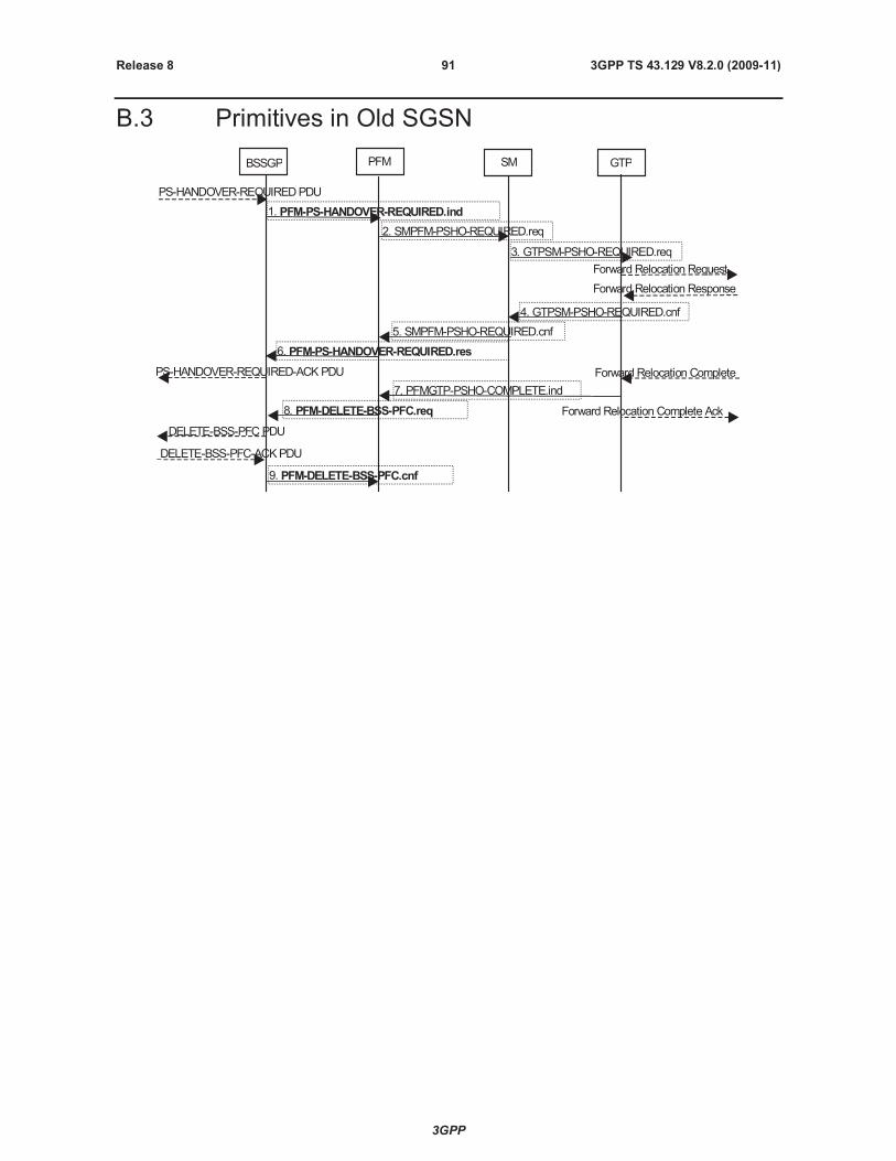
3GPP
3GPP TS 43.129 V8.2.0 (2009-11)91Release 8
B.3 Primitives in Old SGSN
BSSGP PFM SM
2. SMPFM-PSHO-REQUIRED.req
3. GTPSM-PSHO-REQUIRED.req
4. GTPSM-PSHO-REQUIRED.cnf
5. SMPFM-PSHO-REQUIRED.cnf
GTP
1. PFM-PS-HANDOVER-REQUIRED.ind
PS-HANDOVER-REQUIREDPDU
Forward Relocation Request
Forward Relocation Response
PS-HANDOVER-REQUIRED-ACKPDU Forward Relocation Complete
7. PFMGTP-PSHO-COMPLETE.ind
8. PFM-DELETE-BSS-PFC.req
DELETE-BSS-PFCPDU
6. PFM-PS-HANDOVER-REQUIRED.res
DELETE-BSS-PFC-ACKPDU
9. PFM-DELETE-BSS-PFC.cnf
Forward Relocation Complete Ack
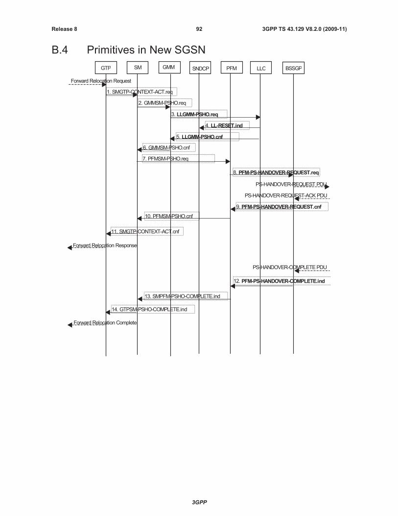
3GPP
3GPP TS 43.129 V8.2.0 (2009-11)92Release 8
B.4 Primitives in New SGSN
GTP GMMSM SNDCP PFM LLC
1. SMGTP-CONTEXT-ACT.req
2. GMMSM-PSHO.req
6. GMMSM-PSHO.cnf
3. LLGMM-PSHO.req
5. LLGMM-PSHO.cnf
BSSGP
7. PFMSM-PSHO.req
8. PFM-PS-HANDOVER-REQUEST.req
10. PFMSM-PSHO.cnf
11. SMGTP-CONTEXT-ACT.cnf
Forward Relocation Request
PS-HANDOVER-REQUEST PDU
PS-HANDOVER-REQUEST-ACKPDU
Forward Relocation Response
PS-HANDOVER-COMPLETEPDU
12. PFM-PS-HANDOVER-COMPLETE.ind
13. SMPFM-PSHO-COMPLETE.ind
14. GTPSM-PSHO-COMPLETE.ind
Forward Relocation Complete
9. PFM-PS-HANDOVER-REQUEST.cnf
4. LL-RESET.ind

3GPP
3GPP TS 43.129 V8.2.0 (2009-11)93Release 8
B.5 Primitives in Target BSS
BSSGP RR
1. PFM-PS-HANDOVER-REQUEST.ind
PS-HANDOVER-REQUESTPDU
2. RRPFM-PSHO.req
RLCData Block
PFM
5. PFMRR-PSHO-COMPLETE.ind
6. PFM-PS-HANDOVER-COMPLETE.req
PS-HANDOVER-COMPLETEPDU
3. RRPFM-PSHO.cnf
PS-HANDOVER-REQUEST-ACKPDU
4. PFM-PS-HANDOVER-REQUEST.res
B.6 Primitives in MS
GMM SM RR
1. GRR-PSHO-SUCCESS.ind
PSHandover Command
LLC
RLCData Blocks
4.GRR-UNITDATA.req
2. LLGMM-PSHO.ind
SNDCP
After theMShas arrived in the newcell it considers the PShandover procedure to be successfullycompleted as a result of one of the following:
TheMS requires timing advance information andhas received the Physical InformationMessage.
TheMShas sent the requested Handover Reference information and does not requiretiming advance information.
TheMSdoes not need to send Handover Reference information and does not require
timing advance information.
3. LL-RESET.ind
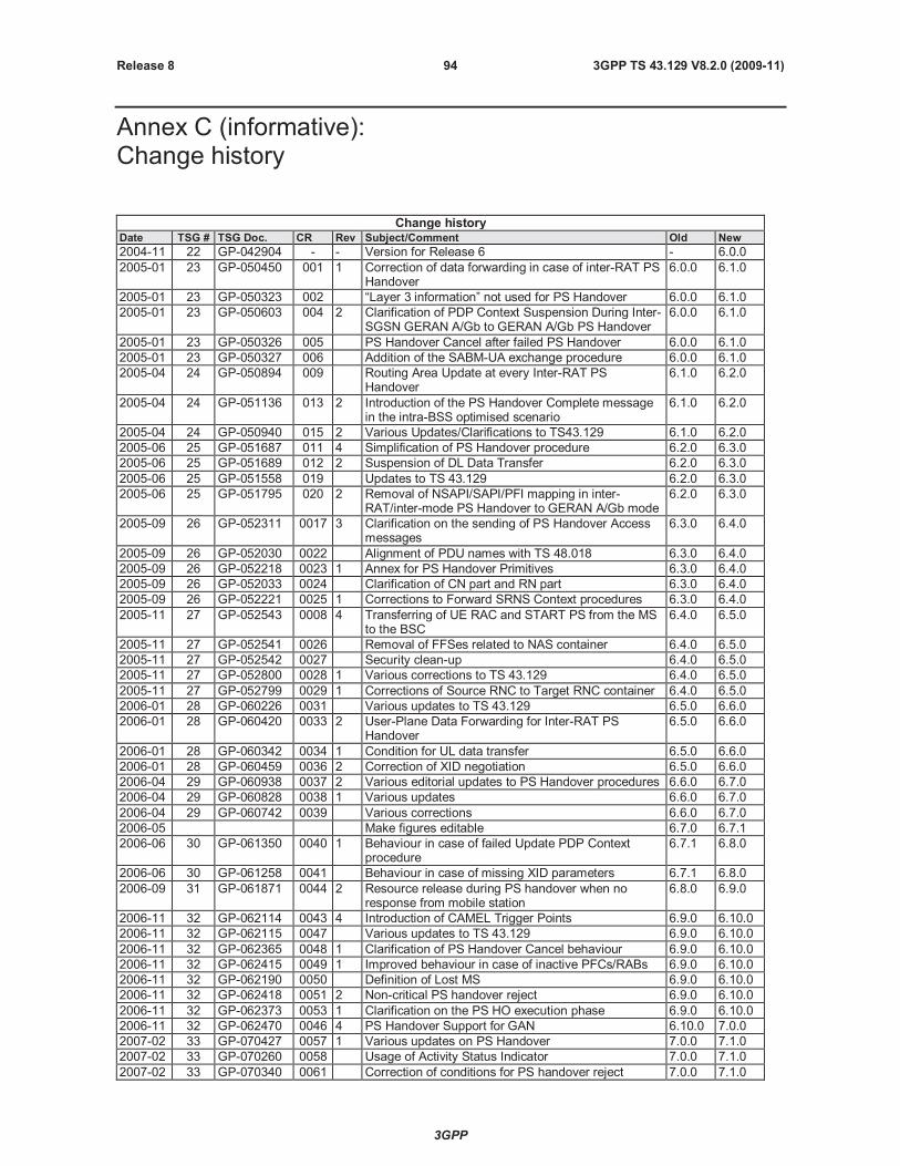
3GPP
3GPP TS 43.129 V8.2.0 (2009-11)94Release 8
Annex C (informative):Change history
Change historyDate TSG # TSG Doc. CR Rev Subject/Comment Old New
2004-11 22 GP-042904 - - Version for Release 6 - 6.0.0
2005-01 23 GP-050450 001 1 Correction of data forwarding in case of inter-RAT PSHandover
6.0.0 6.1.0
2005-01 23 GP-050323 002 “Layer 3 information” not used for PS Handover 6.0.0 6.1.0
2005-01 23 GP-050603 004 2 Clarification of PDP Context Suspension During Inter-SGSN GERAN A/Gb to GERAN A/Gb PS Handover
6.0.0 6.1.0
2005-01 23 GP-050326 005 PS Handover Cancel after failed PS Handover 6.0.0 6.1.0
2005-01 23 GP-050327 006 Addition of the SABM-UA exchange procedure 6.0.0 6.1.0
2005-04 24 GP-050894 009 Routing Area Update at every Inter-RAT PSHandover
6.1.0 6.2.0
2005-04 24 GP-051136 013 2 Introduction of the PS Handover Complete messagein the intra-BSS optimised scenario
6.1.0 6.2.0
2005-04 24 GP-050940 015 2 Various Updates/Clarifications to TS43.129 6.1.0 6.2.0
2005-06 25 GP-051687 011 4 Simplification of PS Handover procedure 6.2.0 6.3.0
2005-06 25 GP-051689 012 2 Suspension of DL Data Transfer 6.2.0 6.3.0
2005-06 25 GP-051558 019 Updates to TS 43.129 6.2.0 6.3.0
2005-06 25 GP-051795 020 2 Removal of NSAPI/SAPI/PFI mapping in inter-RAT/inter-mode PS Handover to GERAN A/Gb mode
6.2.0 6.3.0
2005-09 26 GP-052311 0017 3 Clarification on the sending of PS Handover Accessmessages
6.3.0 6.4.0
2005-09 26 GP-052030 0022 Alignment of PDU names with TS 48.018 6.3.0 6.4.0
2005-09 26 GP-052218 0023 1 Annex for PS Handover Primitives 6.3.0 6.4.0
2005-09 26 GP-052033 0024 Clarification of CN part and RN part 6.3.0 6.4.0
2005-09 26 GP-052221 0025 1 Corrections to Forward SRNS Context procedures 6.3.0 6.4.0
2005-11 27 GP-052543 0008 4 Transferring of UE RAC and START PS from the MSto the BSC
6.4.0 6.5.0
2005-11 27 GP-052541 0026 Removal of FFSes related to NAS container 6.4.0 6.5.0
2005-11 27 GP-052542 0027 Security clean-up 6.4.0 6.5.0
2005-11 27 GP-052800 0028 1 Various corrections to TS 43.129 6.4.0 6.5.0
2005-11 27 GP-052799 0029 1 Corrections of Source RNC to Target RNC container 6.4.0 6.5.0
2006-01 28 GP-060226 0031 Various updates to TS 43.129 6.5.0 6.6.0
2006-01 28 GP-060420 0033 2 User-Plane Data Forwarding for Inter-RAT PSHandover
6.5.0 6.6.0
2006-01 28 GP-060342 0034 1 Condition for UL data transfer 6.5.0 6.6.0
2006-01 28 GP-060459 0036 2 Correction of XID negotiation 6.5.0 6.6.0
2006-04 29 GP-060938 0037 2 Various editorial updates to PS Handover procedures 6.6.0 6.7.0
2006-04 29 GP-060828 0038 1 Various updates 6.6.0 6.7.0
2006-04 29 GP-060742 0039 Various corrections 6.6.0 6.7.0
2006-05 Make figures editable 6.7.0 6.7.1
2006-06 30 GP-061350 0040 1 Behaviour in case of failed Update PDP Contextprocedure
6.7.1 6.8.0
2006-06 30 GP-061258 0041 Behaviour in case of missing XID parameters 6.7.1 6.8.0
2006-09 31 GP-061871 0044 2 Resource release during PS handover when noresponse from mobile station
6.8.0 6.9.0
2006-11 32 GP-062114 0043 4 Introduction of CAMEL Trigger Points 6.9.0 6.10.0
2006-11 32 GP-062115 0047 Various updates to TS 43.129 6.9.0 6.10.0
2006-11 32 GP-062365 0048 1 Clarification of PS Handover Cancel behaviour 6.9.0 6.10.0
2006-11 32 GP-062415 0049 1 Improved behaviour in case of inactive PFCs/RABs 6.9.0 6.10.0
2006-11 32 GP-062190 0050 Definition of Lost MS 6.9.0 6.10.0
2006-11 32 GP-062418 0051 2 Non-critical PS handover reject 6.9.0 6.10.0
2006-11 32 GP-062373 0053 1 Clarification on the PS HO execution phase 6.9.0 6.10.0
2006-11 32 GP-062470 0046 4 PS Handover Support for GAN 6.10.0 7.0.0
2007-02 33 GP-070427 0057 1 Various updates on PS Handover 7.0.0 7.1.0
2007-02 33 GP-070260 0058 Usage of Activity Status Indicator 7.0.0 7.1.0
2007-02 33 GP-070340 0061 Correction of conditions for PS handover reject 7.0.0 7.1.0
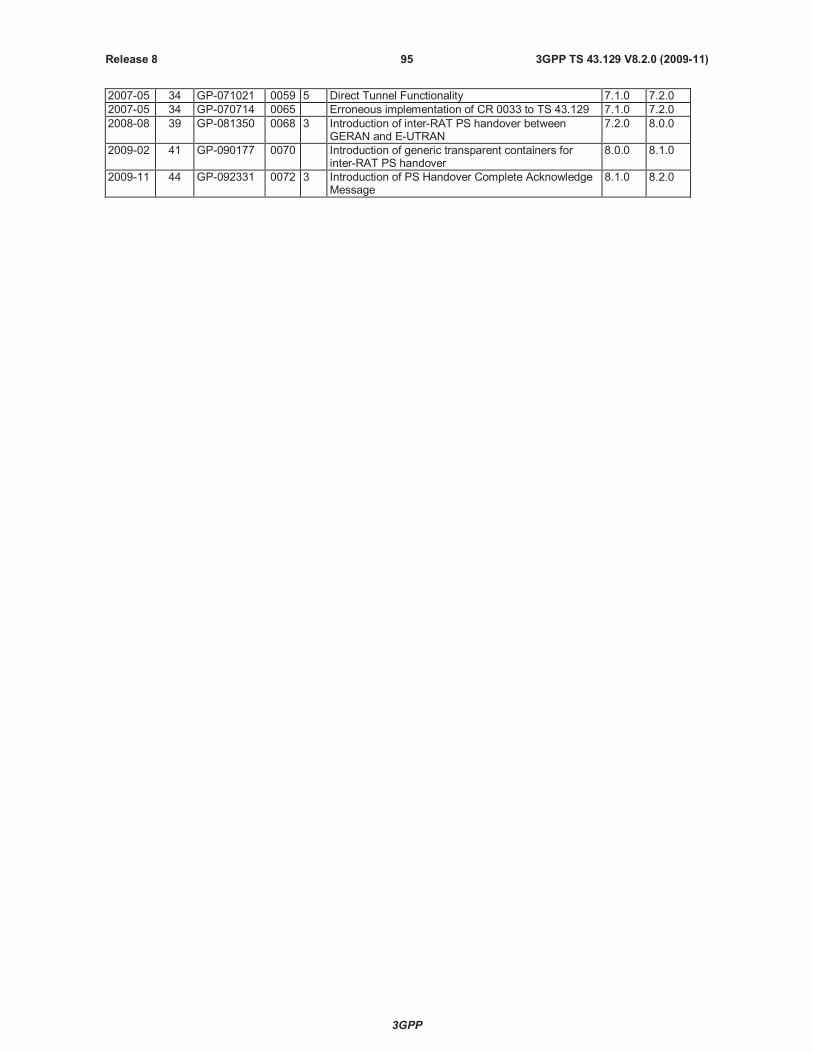
3GPP
3GPP TS 43.129 V8.2.0 (2009-11)95Release 8
2007-05 34 GP-071021 0059 5 Direct Tunnel Functionality 7.1.0 7.2.0
2007-05 34 GP-070714 0065 Erroneous implementation of CR 0033 to TS 43.129 7.1.0 7.2.0
2008-08 39 GP-081350 0068 3 Introduction of inter-RAT PS handover betweenGERAN and E-UTRAN
7.2.0 8.0.0
2009-02 41 GP-090177 0070 Introduction of generic transparent containers forinter-RAT PS handover
8.0.0 8.1.0
2009-11 44 GP-092331 0072 3 Introduction of PS Handover Complete AcknowledgeMessage
8.1.0 8.2.0