3gpp ts 23.402 v8.9 - 株式会社qt · lte, umts, access 3gpp ... 6.2 initial attach on s2a ......
TRANSCRIPT
3GPP TS 23.402 V8.9.0 (2010-06) Technical Specification
3rd Generation Partnership Project;Technical Specification Group Services and System Aspects;
Architecture enhancements for non-3GPP accesses(Release 8)
The present document has been developed within the 3rd Generation Partnership Project (3GPP TM) and may be further elaborated for the purposes of 3GPP. The present document has not been subject to any approval process by the 3GPP Organizational Partners and shall not be implemented. This Specification is provided for future development work within 3GPP only. The Organizational Partners accept no liability for any use of this Specification. Specifications and reports for implementation of the 3GPP TM system should be obtained via the 3GPP Organizational Partners' Publications Offices.

3GPP
3GPP TS 23.402 V8.9.0 (2010-06) 2Release 8
Keywords LTE, UMTS, access
3GPP
Postal address
3GPP support office address 650 Route des Lucioles - Sophia Antipolis
Valbonne - FRANCE Tel.: +33 4 92 94 42 00 Fax: +33 4 93 65 47 16
Internet http://www.3gpp.org
Copyright Notification
No part may be reproduced except as authorized by written permission. The copyright and the foregoing restriction extend to reproduction in all media.
© 2010, 3GPP Organizational Partners (ARIB, ATIS, CCSA, ETSI, TTA, TTC).
All rights reserved.
UMTS™ is a Trade Mark of ETSI registered for the benefit of its members 3GPP™ is a Trade Mark of ETSI registered for the benefit of its Members and of the 3GPP Organizational Partners LTE™ is a Trade Mark of ETSI currently being registered for the benefit of its Members and of the 3GPP Organizational Partners GSM® and the GSM logo are registered and owned by the GSM Association
3GPP
3GPP TS 23.402 V8.9.0 (2010-06) 3Release 8
Contents Foreword ...................................................................................................................................................... 9 Introduction .................................................................................................................................................. 9 1 Scope ................................................................................................................................................ 10 2 References ........................................................................................................................................ 10 3 Definitions, Symbols and Abbreviations............................................................................................ 12 3.1 Definitions ................................................................................................................................................. 12 3.2 Abbreviations............................................................................................................................................. 12 4 Architecture Model and Concepts ..................................................................................................... 13 4.1 Concepts .................................................................................................................................................... 13 4.1.0 General Concepts .................................................................................................................................. 13 4.1.1 General Concepts for Interworking Between E-UTRAN and CDMA2000 ............................................. 13 4.1.2 General Concepts for Interworking Between 3GPP Accesses and WiMAX ............................................ 14 4.1.3 IP Mobility Management Selection Principles ....................................................................................... 14 4.1.3.1 Static Configuration of Inter-technology Mobility Mechanism ......................................................... 14 4.1.3.2 Networks Supporting Multiple IP Mobility Mechanisms .................................................................. 14 4.1.3.2.1 IP Mobility Management Selection During Initial Attach to a Non-3GPP Access ........................ 15 4.1.3.2.2 IPMS solutions ................................................................................................................................ 16 4.1.3.2.3 IP Mobility Management Selection on Handover between accesses .................................................. 16 4.1.4 Trusted/untrusted non-3GPP access network detection .......................................................................... 17 4.2 Architecture Reference Model .................................................................................................................... 17 4.2.1 Architecture for 3GPP Accesses with PMIP-based S5/S8 ...................................................................... 17 4.2.2 Non-roaming Architectures for EPS ...................................................................................................... 18 4.2.3 Roaming Architectures for EPS............................................................................................................. 20 4.3 Network Elements ...................................................................................................................................... 24 4.3.1 Access Networks .................................................................................................................................. 24 4.3.1.1 E-UTRAN ....................................................................................................................................... 24 4.3.1.2 Trusted and Untrusted Non-3GPP Access Network .......................................................................... 24 4.3.2 MME.................................................................................................................................................... 25 4.3.3 Gateway ............................................................................................................................................... 25 4.3.3.1 General ........................................................................................................................................... 25 4.3.3.2 Serving GW .................................................................................................................................... 25 4.3.3.3 PDN GW ........................................................................................................................................ 26 4.3.4 ePDG ................................................................................................................................................... 26 4.3.5 PCRF ................................................................................................................................................... 27 4.3.5.1 Home PCRF .................................................................................................................................... 27 4.3.5.2 Visited PCRF .................................................................................................................................. 27 4.4 Reference Points ........................................................................................................................................ 27 4.4.1 List of Reference Points ........................................................................................................................ 27 4.4.2 Reference Point Requirements .............................................................................................................. 29 4.4.2.1 S5 Reference Point Requirements .................................................................................................... 29 4.4.2.2 Void ................................................................................................................................................ 29 4.4.2.3 Void ................................................................................................................................................ 29 4.4.2.4 Void ................................................................................................................................................ 29 4.5 High Level Functions ................................................................................................................................. 29 4.5.1 PDN GW Selection Function for Non-3GPP Accesses for S2a and S2b ................................................. 29 4.5.2 PDN GW Selection Function for S2c .................................................................................................... 31 4.5.3 Serving GW Selection Function for Non-3GPP Accesses ...................................................................... 31 4.5.4 ePDG Selection .................................................................................................................................... 31 4.5.5 PCRF Selection .................................................................................................................................... 32 4.5.6 DSMIPv6 Home Link Detection Function ............................................................................................. 32 4.6 Identities .................................................................................................................................................... 32 4.6.1 User Identification ................................................................................................................................ 32 4.7 IP Address Allocation ................................................................................................................................ 33 4.7.1 IP Address Allocation with PMIP-based S5/S8 ...................................................................................... 33
3GPP
3GPP TS 23.402 V8.9.0 (2010-06) 4Release 8
4.7.2 IP Address Allocation in Trusted Non-3GPP IP Access using PMIPv6 on S2a ....................................... 37 4.7.3 IP Address Allocation in Untrusted Non-3GPP IP Access using PMIPv6 on S2b ................................... 40 4.7.4 IP Address Allocation using S2c ........................................................................................................... 40 4.8 Network Discovery and Selection ............................................................................................................... 41 4.8.0 General Principles................................................................................................................................. 41 4.8.1 Architecture for Access Network Discovery Support Functions ............................................................. 41 4.8.2 Network Elements ................................................................................................................................ 42 4.8.2.1 Access Network Discovery and Selection Function (ANDSF) .......................................................... 42 4.8.3 Reference Points ................................................................................................................................... 43 4.8.4 ANDSF Discovery ................................................................................................................................ 44 4.8.5 Inter-system Mobility Policies............................................................................................................... 44 4.9 Authentication and Security........................................................................................................................ 44 4.9.1 Access Authentication in non-3GPP Accesses ....................................................................................... 44 4.9.2 Tunnel Authentication .......................................................................................................................... 44 4.10 QoS Concepts ............................................................................................................................................ 45 4.10.1 General ................................................................................................................................................. 45 4.10.2 Void ..................................................................................................................................................... 45 S-GWS-GWS-GW4.10.3 The EPS Bearer with PMIP-based S5/S8 and E-UTRAN access ............................... 45 4.10.4 Application of PCC in the Evolved Packet System ................................................................................ 46 4.11 Charging for Non-3GPP Accesses .............................................................................................................. 46 4.12 Multiple PDN Support ............................................................................................................................... 46 5 Functional Description and Procedures for 3GPP Accesses with PMIP-based S5/S8 .......................... 48 5.1 Control and User Plane Protocol Stacks ...................................................................................................... 48 5.1.1 Void ..................................................................................................................................................... 48 5.1.2 General ................................................................................................................................................. 48 5.1.3 Control Plane ........................................................................................................................................ 48 5.1.3.1 Serving GW - PDN GW .................................................................................................................. 48 5.1.4 User Plane ............................................................................................................................................ 49 5.1.4.1 UE – PDN GW User Plane with E-UTRAN ..................................................................................... 49 5.1.4.2 UE – PDN GW User Plane with 2G access via the S4 Interface ........................................................ 49 5.1.4.3 UE – PDN GW User Plane with 3G Access via the S4 Interface ....................................................... 50 5.1.4.4 UE – PDN-GW User Plane with 3G Access via the S12 Interface..................................................... 50 5.2 Initial E-UTRAN Attach with PMIP-based S5 or S8 ................................................................................... 50 5.3 Detach for PMIP-based S5/S8 .................................................................................................................... 54 5.4 Dedicated Bearer Procedures for E-UTRAN Access with PMIP-based S5/S8 .............................................. 55 5.4.1 General ................................................................................................................................................. 55 5.4.2 Dedicated Bearer Activation ................................................................................................................. 56 5.4.3 Bearer Modification with Bearer QoS Update........................................................................................ 56 5.4.3.1 PCC Initiated Bearer Modification with Bearer QoS Update ............................................................ 56 5.4.3.2 HSS-Initiated Subscribed QoS Modification .................................................................................... 57 5.4.4 Dedicated Bearer Modification without Bearer QoS Update .................................................................. 57 5.4.5 Dedicated Bearer Deactivation .............................................................................................................. 58 5.4.5.1 PCC-initiated Dedicated Bearer Deactivation ................................................................................... 58 5.4.5.2 Void ................................................................................................................................................ 58 5.4.5.3 MME-initiated Dedicated Bearer Deactivation ................................................................................. 58 5.5 UE-initiated Resource Request and Release ................................................................................................ 59 5.6 Multiple PDN Support with PMIP-based S5/S8 .......................................................................................... 60 5.6.1 UE requested PDN connectivity ............................................................................................................ 60 5.6.2 PDN Disconnection .............................................................................................................................. 62 5.6.2.1 UE, MME or S-GW initiated PDN Disconnection ............................................................................ 62 5.6.2.2 PDN-GW-initiated PDN Disconnection ........................................................................................... 63 5.7 Handover and Tracking area Update Procedures for PMIP-based S5/S8 Interface ........................................ 64 5.7.1 Intra-LTE TAU and Inter-eNodeB Handover with Serving GW Relocation ........................................... 64 5.7.2 TAU/RAU or Handover between GERAN A/Gb Mode or UTRAN Iu Mode and E-UTRAN ................. 66 5.8 ME Identity Check Procedures for PMIP-based S5/S8 ................................................................................ 69 5.9 UE-triggered Service Request for PMIP-based S5/S8.................................................................................. 69 5.10 PMIP-based S5/S8 procedures for GERAN/UTRAN over S4 ...................................................................... 70 5.10.1 General ................................................................................................................................................. 70 5.10.2 GPRS procedures that update the PDN GW........................................................................................... 70 5.10.3 UE allocated resources .......................................................................................................................... 71 5.10.4 Network allocated resources.................................................................................................................. 72

3GPP
3GPP TS 23.402 V8.9.0 (2010-06) 5Release 8
5.10.5 UE released resources ........................................................................................................................... 72 5.10.6 PDN GW released resources ................................................................................................................. 72 5.10.7 Attach................................................................................................................................................... 73 5.10.8 Detach interaction using S4 ................................................................................................................... 73 5.10.9 Interaction with CGI/SAI reporting using S4 ......................................................................................... 73 5.10.10 RAU Procedure Support ....................................................................................................................... 73 5.11 PDN GW initiated IPv4 address Delete Procedure ...................................................................................... 73 6 Functional Description and Procedures for Trusted Non-3GPP IP Accesses ...................................... 75 6.1 Control and User Plane Protocol Stacks ...................................................................................................... 75 6.1.1 Protocol Stacks for S2a ......................................................................................................................... 75 6.1.2 Protocol Stacks for S2c over Trusted Non-3GPP IP Accesses ................................................................ 76 6.2 Initial Attach on S2a................................................................................................................................... 77 6.2.1 Initial Attach Procedure with PMIPv6 on S2a and Anchoring in PDN GW ............................................ 77 6.2.2 Void ..................................................................................................................................................... 79 6.2.3 Initial Attach procedure with MIPv4 FACoA on S2a and Anchoring in PDN-GW ................................. 79 6.2.4 Initial Attach Procedure with PMIPv6 on S2a and Chained S2a and PMIP-based S8 .............................. 81 6.3 Initial Attach Procedure with DSMIPv6 on S2c in Trusted Non-3GPP IP Access ........................................ 83 6.4 Detach and PDN Disconnection for S2a...................................................................................................... 86 6.4.1 UE/Trusted Non-3GPP IP Access Network Initiated Detach and UE/Trusted Non-3GPP IP Access
requested PDN Disconnection Procedure with PMIPv6 ......................................................................... 86 6.4.1.1 Non-Roaming, Home Routed Roaming and Local Breakout Case ..................................................... 86 6.4.1.2 Chained PMIP-based S8-S2a Roaming Case .................................................................................... 88 6.4.2 HSS/AAA Initiated Detach Procedure with PMIPv6 .............................................................................. 89 6.4.2.1 Non-Roaming, Home Routed Roaming and Local Breakout Case ..................................................... 89 6.4.2.2 Chained PMIP-based S8-S2a Roaming Case .................................................................................... 90 6.4.3 UE-initiated Detach Procedure and UE-Requested PDN Disconnection Procedure with MIPv4
FACoA ................................................................................................................................................. 91 6.4.4 Network Initiated Detach Procedure with MIPv4 FACoA ...................................................................... 92 6.4.5 HSS/AAA-initiated detach procedure with MIPv4 FACoA .................................................................... 93 6.5 Detach and PDN Disconnection for S2c in Trusted Non-3GPP IP Access.................................................... 94 6.5.1 General ................................................................................................................................................. 94 6.5.2 UE-initiated PDN disconnection Procedure ........................................................................................... 95 6.5.3 HSS-initiated Detach Procedure ............................................................................................................ 96 6.5.4 PDN-GW-initiated PDN Disconnection Procedure ................................................................................ 97 6.6 Network-initiated Dynamic PCC ................................................................................................................ 98 6.6.1 Network-initiated Dynamic PCC on S2a ............................................................................................... 98 6.6.2 Network-initiated Dynamic PCC for S2c over Trusted Non-3GPP IP Access ......................................... 99 6.7 UE-initiated Resource Request and Release .............................................................................................. 100 6.7.1 UE-initiated Resource Request and Release on S2a ............................................................................. 100 6.7.2 UE-initiated Resource Request for S2c over Trusted Non-3GPP IP Access .......................................... 101 6.8 UE-initiated Connectivity to Additional PDN ........................................................................................... 101 6.8.1 UE-initiated Connectivity to Additional PDN with PMIPv6 on S2a ..................................................... 101 6.8.1.1 Non-Roaming, Home Routed Roaming and Local Breakout Case ................................................... 101 6.8.1.2 Chained PMIP-based S8-S2a Roaming Case .................................................................................. 103 6.8.2 UE-initiated Connectivity to Additional PDN with MIPv4 FACoA on S2a .......................................... 104 6.8.3 UE-initiated Connectivity to Additional PDN from Trusted Non-3GPP IP Access with DSMIPv6 on
S2c ..................................................................................................................................................... 105 6.9 Void ........................................................................................................................................................ 105 6.10 PDN GW reallocation upon attach on S2c ................................................................................................ 105 6.11 S2c Bootstrapping via DSMIPv6 Home Link over a Trusted Access ......................................................... 106 6.12 PDN GW initiated Resource Allocation Deactivation................................................................................ 107 6.12.1 PDN GW initiated Resource Allocation Deactivation with S2a PMIP .................................................. 107 6.12.2 PDN GW initiated Resource Allocation Deactivation with S2a MIPv4 ................................................ 108 6.12.3 PDN GW initiated Resource Allocation Deactivation for Chained PMIP-based S8-S2a Roaming ......... 109 6.12.4 Void ................................................................................................................................................... 110 6.13 PDN GW initiated IPv4 address Delete Procedure .................................................................................... 110 6.14 Non-3GPP access initiated IPv4 address Delete Procedure ........................................................................ 111 6.15 IPv4 Home Address Release Procedure for S2c ........................................................................................ 112 7 Functional Description and Procedures for Un-trusted Non-3GPP IP Accesses ................................ 113 7.1 Control and User Plane Protocol Stacks .................................................................................................... 113

3GPP
3GPP TS 23.402 V8.9.0 (2010-06) 6Release 8
7.1.1 Protocol Options for S2b ..................................................................................................................... 113 7.1.2 Protocol Options for S2c over Un-trusted Non-3GPP IP Accesses ....................................................... 114 7.2 Initial Attach on S2b with PMIPv6 ........................................................................................................... 115 7.2.1 Initial Attach with PMIPv6 on S2b ...................................................................................................... 115 7.2.2 Void ................................................................................................................................................... 116 7.2.3 Initial Attach Procedure with PMIPv6 on S2b and Chained S2b and PMIP-based S8............................ 117 7.3 Initial Attach Procedure for S2c in Untrusted Non-3GPP IP Access .......................................................... 117 7.4 Detach and PDN Disconnection for S2b ................................................................................................... 118 7.4.1 UE/ePDG-initiated Detach Procedure and UE-Requested PDN Disconnection with PMIPv6................ 118 7.4.1.1 Non-Roaming, Home Routed Roaming and Local Breakout Case ................................................... 118 7.4.1.2 Chained PMIP-based S8-S2b Roaming Case .................................................................................. 119 7.4.2 HSS/AAA-initiated Detach Procedure with PMIP ............................................................................... 120 7.4.2.1 Non-Roaming, Home Routed Roaming and Local Breakout Case ................................................... 120 7.4.2.2 Chained PMIP-based S8-S2b Roaming Case .................................................................................. 120 7.5 Detach and PDN Disconnection for S2c in Un-trusted Non-3GPP IP Access ............................................. 120 7.5.1 General ............................................................................................................................................... 120 7.5.2 UE-Initiated PDN disconnection Procedure ......................................................................................... 121 7.5.3 HSS-initiated Detach Procedure .......................................................................................................... 122 7.5.4 PDN GW-initiated PDN Disconnection Procedure .............................................................................. 123 7.6 UE-initiated Connectivity to Additional PDN ........................................................................................... 125 7.6.1 UE-initiated Connectivity to Additional PDN with PMIPv6 on S2b ..................................................... 125 7.6.2 UE-initiated Connectivity to Additional PDN from Un-trusted Non-3GPP IP Access with DSMIPv6
on S2c ................................................................................................................................................ 125 7.7 Void ........................................................................................................................................................ 126 7.8 S2c Bootstrapping via DSMIPv6 Home Link over an Un-Trusted Access ................................................. 126 7.9 PDN GW initiated Resource Allocation Deactivation................................................................................ 126 8 Handovers without Optimizations Between 3GPP Accesses and Non-3GPP IP Accesses ................. 126 8.1 Common Aspects for Handover without Optimizations for Multiple PDNs ............................................... 126 8.2 Handovers between non-3GPP IP access with PMIPv6 on S2a/S2b and 3GPP Access ............................... 128 8.2.1 Handover from Trusted or Untrusted Non-3GPP IP Access with PMIPv6 on S2a/S2b to 3GPP
Access ................................................................................................................................................ 128 8.2.1.1 General Procedure for GTP based S5/S8 for E-UTRAN Access ..................................................... 128 8.2.1.2 Using PMIP-based S5/S8............................................................................................................... 131 8.2.1.3 General Procedure for GTP-based S5/S8 for UTRAN/GERAN ...................................................... 133 8.2.1.4 Using PMIP-based S5/S8............................................................................................................... 136 8.2.2 3GPP Access to Trusted Non-3GPP IP Access Handover with PMIPv6 on S2a .................................... 137 8.2.3 E-UTRAN to Untrusted Non-3GPP IP Access Handover with PMIPv6 on S2b .................................... 140 8.2.4 Void ................................................................................................................................................... 141 8.2.5 Void ................................................................................................................................................... 141 8.2.6 Non-3GPP IP Access to 3GPP Access Handover with PMIPv6 on S2a/b for Chained PMIP-based S8 .. 141 8.2.7 3GPP Access to Non-3GPP IP Access Handover with PMIPv6 on S2a/b for Chained PMIP-based S8 .. 142 8.2.8 Void ................................................................................................................................................... 145 8.2.9 Void ................................................................................................................................................... 145 8.3 Handover from 3GPP access to Trusted Non-3GPP IP Access with MIPv4 FACoA on S2a ....................... 146 8.4 Handovers with DSMIPv6 on S2c ............................................................................................................ 148 8.4.1 Trusted or Untrusted Non-3GPP IP Access with DSMIPv6 over S2c to 3GPP Access Handover .......... 148 8.4.2 3GPP Access to Trusted Non-3GPP IP Access Handover with DSMIPv6 over S2c .............................. 149 8.4.3 3GPP Access to Untrusted Non-3GPP IP Access Handover with DSMIPv6 over S2c ........................... 151 8.5 Handover with Access Network Discovery and Selection.......................................................................... 153 8.5.1 Handover between 3GPP Access and Trusted / Untrusted Non-3GPP IP Access with access network
discovery and selection ....................................................................................................................... 153 9 Handovers with Optimizations Between E-UTRAN Access and CDMA2000 Access ...................... 155 9.1 Architecture and Reference Points ............................................................................................................ 155 9.1.1 Architecture for Optimized Handovers between E-UTRAN Access and cdma2000 HRPD Access ....... 155 9.1.2 Reference Points ................................................................................................................................. 156 9.1.2.1 Reference Point List ...................................................................................................................... 156 9.1.2.2 Requirements for the S101 Reference Point ................................................................................... 156 9.1.2.3 S101 Protocol Stack ...................................................................................................................... 157 9.1.2.4 S101 Session Identifier .................................................................................................................. 157 9.1.2.5 Requirements for the S103 Reference Point ................................................................................... 157

3GPP
3GPP TS 23.402 V8.9.0 (2010-06) 7Release 8
9.1.2.6 S103 Protocol Stack ...................................................................................................................... 157 9.2 Overview of Handover Procedures ........................................................................................................... 158 9.3 Optimized Active Handover: E-UTRAN Access to cdma2000 HRPD Access ........................................... 158 9.3.0 Introduction ........................................................................................................................................ 158 9.3.1 Pre-registration Phase ......................................................................................................................... 159 9.3.2 Handover Phase .................................................................................................................................. 161 9.4 Optimized Idle-mode Mobility: E-UTRAN Access to cdma2000 HRPD Access ........................................ 163 9.5 Optimised Active Handover: cdma2000 HRPD Access to EUTRAN ......................................................... 165 9.5.1 General Procedure for GTP-based S5/S8 ............................................................................................. 165 9.5.2 Using PMIP-based S5/S8 .................................................................................................................... 167 9.6 Optimized Idle Mode Mobility: cdma2000 HRPD Access to E-UTRAN Access........................................ 168 9.7 S101 Tunnel Redirection Procedure .......................................................................................................... 169 10 Handovers with Optimizations Between 3GPP Accesses and Mobile WiMAX ................................ 170 10.1 Optimizations for network-controlled dual radio handover ........................................................................ 170 10.1.1 General Principles............................................................................................................................... 170 11 Handover Optimizations Applicable to All Non-3GPP Accesses ..................................................... 171 12 Interactions Between HSS and AAA Server .................................................................................... 171 12.0 General .................................................................................................................................................... 171 12.1 Location Management Procedures ............................................................................................................ 171 12.1.1 UE Registration Notification ............................................................................................................... 172 12.1.2 AAA-initiated UE De-registration Notification .................................................................................... 172 12.1.3 HSS-initiated UE De-registration Notification ..................................................................................... 173 12.1.4 PDN GW Identity Notification ............................................................................................................ 173 12.2 Subscriber Profile Management Procedures .............................................................................................. 174 12.2.1 HSS-initiated User Profile Update Procedure ...................................................................................... 174 12.2.2 AAA-initiated Provide User Profile Procedure .................................................................................... 174 12.3 Authentication Procedures ........................................................................................................................ 175 13 Information Storage ........................................................................................................................ 175 13.0 General .................................................................................................................................................... 175 13.1 HSS ......................................................................................................................................................... 175 13.2 MME ....................................................................................................................................................... 175 13.3 S-GW ...................................................................................................................................................... 176 13.4 Handling of Wild Card APN .................................................................................................................... 176 14 Void ............................................................................................................................................... 176 15 Functional Description and Procedures for 3GPP Accesses with S2c ............................................... 176 15.1 S2c Bootstrapping via DSMIPv6 Home Link ............................................................................................ 176
3GPP
3GPP TS 23.402 V8.9.0 (2010-06) 8Release 8
Annex A (informative): GTP - PMIP Roaming.............................................................................. 178 A.1 Direct Peering Scenario................................................................................................................... 178 A.2 Proxy-based interworking ............................................................................................................... 180
Annex B (informative): Guidance for Contributors to this Specification ..................................... 182
Annex C (informative): Handover Flows Between Non-3GPP Accesses ....................................... 183 C.1 General ........................................................................................................................................... 183 C.2 Trusted Non-3GPP IP Access to Trusted Non-3GPP IP Access with DSMIPv6 over S2c
Handover ........................................................................................................................................ 183 C.3 Untrusted Non-3GPP IP Access with PMIPv6 to Trusted Non-3GPP IP Access with PMIPv6
Handover in the Non-Roaming Scenario ......................................................................................... 184 C.4 Trusted/Untrusted Non-3GPP IP Access with DSMIPv6 to Trusted Non-3GPP IP Access with
PMIPv6 Handover in the Non-Roaming Scenario ............................................................................ 185 C.5 Handover Between Two Untrusted Non-3GPP IP Accesses Connected to the Same ePDG .............. 187
Annex D: Void ................................................................................................................................ 189
Annex E (Informative): Gateway Relocation in the Trusted Non-3GPP IP Access ...................... 190 E.1 Gateway Relocation with PMIPv6 on S2a ....................................................................................... 190 E.2 Gateway Relocation with MIPv4 FACoA on S2a ............................................................................ 191
Annex F (informative): Change history ......................................................................................... 193
3GPP
3GPP TS 23.402 V8.9.0 (2010-06) 9Release 8
Foreword This Technical Specification has been produced by the 3rd Generation Partnership Project (3GPP).
The contents of the present document are subject to continuing work within the TSG and may change following formal TSG approval. Should the TSG modify the contents of the present document, it will be re-released by the TSG with an identifying change of release date and an increase in version number as follows:
Version x.y.z
where:
x the first digit:
1 presented to TSG for information;
2 presented to TSG for approval;
3 or greater indicates TSG approved document under change control.
y the second digit is incremented for all changes of substance, i.e. technical enhancements, corrections, updates, etc.
z the third digit is incremented when editorial only changes have been incorporated in the document.
Introduction Guidance to Readers of this Specification
In order to reduce the number of procedures in this specification certain editorial practices have been adopted. Though there are many independent factors, such as variants of S5/S8 and attachment cases, these are in essence quite similar. So, rather than presenting the permutations of these factors separately and thereby needlessly repeating normative text, conventions have been adopted to combine this information in single procedures.
The S5 and S8 reference points in the EPC architecture have been defined to have both a GTP and PMIP variant. The GTP variant is documented in TS 23.401 [4], while the PMIP variant is documented in this specification. Every effort has been made to eliminate duplication of normative text common to both specifications. Many figures in this specification refer to procedures in TS 23.401 [4] to achieve this end. Common procedures between TS 23.401 [4] and TS 23.402, are represented in this specification in figures by text in shaded box(es) that reference the appropriate figure and steps in TS 23.401 [4]. The details of the common steps are only captured in TS 23.401 [4].
Attachment cases (as discussed in clauses 6.2.1 and 7.2.1) have been combined in a single figure. The different attachment cases can be accommodated by including optional items in the flows, for instance, a vPCRF that is only employed during when a roaming case or LBO is specified.
Multiple APN interactions may occur for many of the procedures defined in this specification. These interactions complicate the flows by introducing certain operations that may occur multiple times. Rather than produce unique flows for this purpose, we indicate where this possibility may occur in text.
3GPP
3GPP TS 23.402 V8.9.0 (2010-06) 10Release 8
1 Scope This document specifies the stage 2 service description for providing IP connectivity using non-3GPP accesses to the Evolved 3GPP Packet Switched domain. In addition, for E-UTRAN and non-3GPP accesses, the specification describes the Evolved 3GPP PS Domain where the protocols between its Core Network elements are IETF-based.
ITU-T Recommendation I.130 [2] describes a three-stage method for characterisation of telecommunication services, and ITU-T Recommendation Q.65 [3] defines stage 2 of the method.
The specification covers both roaming and non-roaming scenarios and covers all aspects, including mobility between 3GPP and non 3GPP accesses, policy control and charging, and authentication, related to the usage of non-3GPP accesses.
TS 23.401 [4] covers architecture aspects common to the Evolved 3GPP Packet Switched domain.
2 References The following documents contain provisions which, through reference in this text, constitute provisions of the present document.
References are either specific (identified by date of publication, edition number, version number, etc.) or non-specific.
For a specific reference, subsequent revisions do not apply.
For a non-specific reference, the latest version applies. In the case of a reference to a 3GPP document (including a GSM document), a non-specific reference implicitly refers to the latest version of that document in the same Release as the present document.
[1] 3GPP TR 21.905: "Vocabulary for 3GPP Specifications".
[2] ITU-T Recommendations I.130: "Method for the characterization of telecommunication services supported by an ISDN and network capabilities of an ISDN".
[3] ITU-T Recommendation Q.65: "The unified functional methodology for the characterization of services and network capabilities".
[4] 3GPP TS 23.401: "GPRS Enhancements for E-UTRAN Access".
[5] 3GPP TS 23.234: "3GPP System to Wireless Local Area Network (WLAN) Interworking; System Description".
[6] 3GPP TS 36.300: "Evolved Universal Terrestrial Radio Access (E-UTRA) and Evolved Universal Terrestrial Radio Access Network (E-UTRAN); Overall description Stage 2".
[7] 3GPP TS 33.234: "3G security; Wireless Local Area Network (WLAN) interworking security".
[8] IETF RFC 5213: "Proxy Mobile IPv6".
[9] IETF RFC 4306, "Internet Key Exchange Protocol Version 2".
[10] IETF RFC 5555: "Mobile IPv6 support for dual stack Hosts and Routers (DSMIPv6)".
[11] IETF RFC 3748: "Extensible Authentication Protocol (EAP)".
[12] IETF RFC 3344, "Mobility Support for IPv4".
[13] IETF RFC 4285, "Authentication Protocol for Mobile IPv6".
[14] IETF RFC 3775, "Mobility Support in IPv6".
[15] IETF RFC 4282, "The Network Access Identifier".
3GPP
3GPP TS 23.402 V8.9.0 (2010-06) 11Release 8
[16] 3GPP TS 23.003: "Numbering, addressing and identification".
[17] IETF Internet-Draft, draft-ietf-netlmm-pmip6-ipv4-support-05: "IPv4 Support for Proxy Mobile IPv6" work in progress.
[18] IETF RFC 4555, "IKEv2 Mobility and Multihoming Protocol (MOBIKE)"
[19] 3GPP TS 23.203: "Policy and Charging Control Architecture".
[20] 3GPP TS 22.278: "Service requirements for evolution of the system architecture".
[21] 3GPP TS 23.060: "GPRS Tunnelling Protocol (GTP) across the Gn and Gp interface".
[22] IETF RFC 4877, "Mobile IPv6 Operation with IKEv2 and the Revised IPsec Architecture".
[23] IETF RFC 2784, "Generic Routing Encapsulation (GRE)".
[24] IETF RFC 2890, "Key and Sequence Number Extensions to GRE".
[25] IETF RFC 3543, "Registration Revocation in Mobile IPv4".
[26] 3GPP TS 29.212: "Policy and charging control over Gx reference point".
[27] 3GPP TS 29.214: "Policy and charging control over Rx reference point".
[28] IETF RFC 2131: "Dynamic Host Configuration Protocol".
[29] IETF RFC 4039: "Rapid Commit Option for the Dynamic Host Configuration Protocol version 4 (DHCPv4)".
[30] IETF RFC 3736: "Stateless Dynamic Host Configuration Protocol (DHCP) Service for IPv6".
[31] Void.
[32] 3GPP2 C.S0024-A v2.0: "cdma2000 High Rate Packet Data Air Interface Specification".
[33] IETF RFC 4283: "Mobile Node Identifier Option for Mobile IPv6 (MIPv6)".
[34] IETF RFC 2794: "Mobile IP Network Access Identifier Extension for IPv4".
[35] IETF Internet-Draft, draft-ietf-mext-binding-revocation-01, "Binding Revocation for IPv6 Mobility", work in progress.
[36] IETF Internet-Draft, draft-ietf-netlmm-grekey-option-01:"GRE Key Option for Proxy Mobile IPv6" work in progress.
[37] Void.
[38] IETF RFC 4861: "Neighbor Discovery for IP Version 6 (IPv6)".
[39] IETF RFC 5446: "Service Selection for Mobile IPv4".
[40] IETF RFC 5026: "Mobile IPv6 bootstrapping in split scenario".
[41] IETF Internet-Draft, draft-ietf-mip6-bootstrapping-integrated-dhc-05: "MIP6-bootstrapping for the Integrated Scenario", work in Progress.
[42] Void.
[43] IETF Internet-Draft, draft-ietf-dime-pmip6-01.txt: "Diameter Proxy Mobile IPv6: Mobile Access Gateway and Local Mobility Anchor Interaction with Diameter Server", work in progress.
[44] IETF RFC 5447: "Diameter Mobile IPv6: Support for Network Access Server to Diameter Server Interaction".
[45] 3GPP TS 33.402: "3GPP System Architecture Evolution: Security aspects of non-3GPP accesses".

3GPP
3GPP TS 23.402 V8.9.0 (2010-06) 12Release 8
[46] 3GPP TS 31.102: "Characteristics of the Universal Subscriber Identity Module (USIM) application".
[47] 3GPP TS 22.011: "Service accessibility".
[48] IETF RFC 3948: "UDP Encapsulation of IPsec ESP Packets".
[49] 3GPP2 C.S0087-0: "E-UTRAN - HRPD and CDMA2000 1x Connectivity and Interworking: Air Interface Aspects".
[50] IETF RFC 4739: " Multiple Authentication Exchanges in the Internet Key Exchange (IKEv2) Protocol".
[51] 3GPP2 X.P0057-0: "E-UTRAN - eHRPD Connectivity and Interworking: Core Network Aspects", work in progress.
[52] 3GPP TS 36.331: "Evolved Universal Terrestrial Radio Access (E-UTRA); Radio Resource Control (RRC); Protocol specification".
[53] 3GPP TS 23.122: "Non-Access-Stratum (NAS) functions related to Mobile Station (MS) in idle mode".
[54] 3GPP TS 24.302: "Access to the 3GPP Evolved Packet Core (EPC) via non-3GPP access networks".
3 Definitions, Symbols and Abbreviations
3.1 Definitions For the purposes of the present document, the terms and definitions given in TR 21.905 [1] and the following apply. A term defined in the present document takes precedence over the definition of the same term, if any, in TR 21.905 [1].
SectorID or Sector Address Identifier: This identifier is defined in 3GPP2 C.S0024-A v2.0 [32] and is used to identify an HRPD AN. The Network operator shall set the value of the SectorID according to the rules specified in clause 14.9 of 3GPP2 C.S0024-A v2.0 [32].
3.2 Abbreviations For the purposes of the present document, the abbreviations given in TR 21.905 [1] and the following apply. An abbreviation defined in the present document takes precedence over the definition of the same abbreviation, if any, in TR 21.905 [1].
CCoA Collocated Care-of-address DSMIPv6 Dual-Stack MIPv6 EPC Evolved Packet Core ePDG Evolved Packet Data Gateway EPS Evolved Packet System FACoA Foreign Agent Care-of-Address GW Gateway HRPD High Rate Packet Data HS-GW HRPD Serving Gateway IPMS IP Mobility management Selection LMA Local Mobility Anchor MAG Mobile Access Gateway MIPv4 Mobile IP version 4 MIPv6 Mobile IP version 6 MME Mobility Management Entity P-GW PDN Gateway PMIP/PMIPv6 Proxy Mobile IP version 6 SectorID Sector Address Identifier

3GPP
3GPP TS 23.402 V8.9.0 (2010-06) 13Release 8
S-GW Serving GW
4 Architecture Model and Concepts
4.1 Concepts
4.1.0 General Concepts The EPS supports the use of non-3GPP IP access networks to access the EPC.
The EPS supports IETF-based network-based mobility management mechanism (e.g., PMIP) and host-based mobility management mechanism (e.g., MIP) over S2 reference points.
The EPS supports IETF-based network-based mobility management mechanism (e.g., PMIP) over S5, and S8 reference points.
When host-based mobility protocol (DSMIPv6 [10]) is used within the EPS and the UE camps on a 3GPP access network, in this specification the UE is considered to be on its home link.
NOTE 1: A scenario where the UE in EPS uses a host based mobility protocol with a HA that is outside the EPS is out of the scope of 3GPP specification.
The mobility management procedures specified to handle mobility between 3GPP and non 3GPP accesses shall include mechanisms to minimize the handover latency due to authentication and authorization for network access. This applies to UEs either supporting simultaneous radio transmission capability or not supporting it. EPS-based mobility between GERAN/UTRAN access and non-3GPP access requires S4-based SGSNs.
For multiple PDN-GWs connecting to the same PDN, all the PDN GWs shall support the same mobility protocols.
The EPC supports local breakout of traffic whether a roaming subscriber is accessing the EPC via a 3GPP or a non 3GPP access network according to the design principles described in clause 4.1 of TS 23.401 [4].
The full support for connecting an UE simultaneously to the EPC via more than one access network is out of the scope of this release of the specification. This release supports simultaneous access from more than one access network during handover between the access networks.
NOTE 2: Even though not explicitly supported by this specification, the mechanisms specified in this specification can be used to connect a UE in parallel to the EPC via 3GPP access network and a Non-3GPP access network towards different PDNs.
4.1.1 General Concepts for Interworking Between E-UTRAN and CDMA2000
The mobility management procedures specified to handle mobility between E-UTRAN and CDMA2000 accesses (as required by TS 22.278 [20]) shall include mechanisms to minimize the service interruption during handover and where possible support bidirectional service continuity.
- This applies to UEs supporting either single or dual radio capability.
- The mobility management procedures should minimize any performance impacts to the UE and the respective accesses, for example, UE battery consumption and network throughput.
- The mobility management procedures should minimize the coupling between the different accesses allowing independent protocol evolution in each access.

3GPP
3GPP TS 23.402 V8.9.0 (2010-06) 14Release 8
4.1.2 General Concepts for Interworking Between 3GPP Accesses and WiMAX
The mobility management procedures specified to handle mobility between 3GPP Accesses and WiMAX (as required by TS 22.278 [20]) shall include mechanisms to minimize the service interruption during handover and where possible support bidirectional service continuity.
- This applies to UEs supporting either single or dual radio capability.
- The mobility management procedures should minimize any performance impacts to the UE and the respective accesses, for example, UE battery consumption and network throughput.
- The mobility management procedures should minimize the coupling between the different accesses allowing independent protocol evolution in each access.
Furthermore, the mobility management procedures specified to handle mobility between 3GPP accesses and WiMAX should minimize the impact on legacy systems (i.e. UTRAN and GERAN).
4.1.3 IP Mobility Management Selection Principles The Mobility mechanisms supported between 3GPP and non-3GPP accesses within an operator and its roaming partner's network would depend upon operator choice.
4.1.3.1 Static Configuration of Inter-technology Mobility Mechanism
For networks deploying a single IP mobility management mechanism, the statically configured mobility mechanism can be access type and/or roaming agreement specific. The information about the mechanism to be used in such scenario is expected to be provisioned into the terminal (or the UICC) and the network. IP session continuity between 3GPP and non-3GPP access types may not be provided in this case if there is a mismatch between what the UE expects and what the network supports. For example service continuity may not be possible if the user switches to a terminal supporting a different IP mobility management mechanism than provisioned in the network.
NOTE: The mismatch case where a trusted non-3GPP network or ePDG only supports DSMIPv6 and the UE does not, may lead to a situation where the UE receives a local IP address in the trusted non-3GPP access network or ePDG, but gains no PDN connectivity in the EPC. Depending on operator policy and roaming agreements, IP connectivity may be provided using this local IP address to access services (e.g. internet access) in the trusted non-3GPP network. However, any such use of the local IP address where the user traffic does not use the EPC is not described in this specification.
4.1.3.2 Networks Supporting Multiple IP Mobility Mechanisms
IP Mobility management Selection (IPMS) consist of two components:
- IP MM protocol selection between Network Based Mobility (NBM) and Host based mobility (HBM - MIPv4 orDSMIPv6).
- Decision on IP address preservation if NBM is selected.
IPMS does not relate to the selection between PMIv6P and GTP over S5/S8.
Upon initial attachment to a 3GPP access, no IPMS is necessary since connectivity to a PDN GW is always established with a network-based mobility mechanism.
Upon initial attachment to a trusted non-3GPP access or ePDG and upon handover from 3GPP to a trusted non-3GPP access or ePDG, IPMS is performed before an IP address is allocated and provided to the UE.
The UE support for a specific IP Mobility Management protocol and/or IP address preservation mechanism for inter-access mobility may be known by the network-based on explicit indication from the UE.
Upon attachment to a trusted non-3GPP access or ePDG, if the access network (supporting at least PMIP6v6) is not aware of the UE capabilities and the home and access network's policies allow the usage of PMIPv6, then PMIPv6 is used for establishing connectivity for the UE to the EPC.
3GPP
3GPP TS 23.402 V8.9.0 (2010-06) 15Release 8
When a NBM mechanism is used for establishing connectivity in the target access upon inter-access mobility, IP address preservation for session continuity based on NBM may take place as per PMIPv6 specification, RFC 5213 [8] and additionally based on the knowledge in the network of UE's capability (if available) to support NBM. Such knowledge may be based on an explicit indication from the UE upon handover that IP address preservation based on NBM management can be provided.
IP address preservation for session continuity based on HBM may take place if the network is aware of the UE capability to support DSMIPv6 or MIPv4. Such knowledge may be based on an indication to the target trusted non-3GPP access or ePDG from the HSS/AAA (e.g. in case of DSMIPv6, the UE performed S2c bootstrap before moving to the target trusted non-3GPP access or ePDG). In such a case, the trusted non-3GPP access network or ePDG provides the UE with a new IP address, local to the access network if IP mobility management protocol selected is DSMIPv6. In that case, in order to get IP address preservation for session continuity, the UE shall use DSMIPv6 over S2c reference point. This IP address shall be used as a care-of address for DSMIPv6, and any other use is out of scope of this specification. If the IP mobility management protocol selected is MIPv4, the address provided to the UE by the non-3GPP access network is a FACoA and IP address preservation is performed over S2a using MIPv4 FACoA procedures.
The final decision on the mobility management mechanism is made by the HSS/AAA upon UE authentication in the trusted non-3GPP access system or ePDG (both at initial attachment and handover), based on the information it has regarding the UE, local/home network capabilities and local/home network policies. If the UE provided an explicit indication of the supported mobility mechanisms, the network shall provide an indication to the UE identifying the selected mobility management mechanism.
Support of different IP mobility management protocols at local/home network is known by the AAA/HSS in one of the following ways:
- through static pre-configuration, or
- through indication of the supported IP mobility management protocols (PMIPv6 and/or MIPv4 FA CoA mode) by the trusted non-3GPP access system or ePDG as part of the AAA exchange for UE authentication.
Upon selecting a mobility management mechanism, as part of the AAA exchange for UE authentication in the trusted non-3GPP access system or ePDG, the HSS/AAA returns to the trusted non-3GPP access system or ePDG an indication on whether a local IP address shall be allocated to the UE, or if instead PMIPv6 shall be used to establish the connectivity, or the HSS/AAA returns to the trusted non-3GPP access system an indication that the address of the MIPv4 Foreign Agent shall be provided to the UE.
IPMS is performed in the following scenarios:
- Upon initial attach to a trusted non-3GPP access or ePDG, the IPMS is performed to decide how to establish IP connectivity for the UE.
- Upon handover without optimization from a 3GPP access to a non-3GPP access, the IPMS is performed to decide how to establish IP connectivity for the UE over the trusted non-3GPP access or ePDG.
- Upon change of access between a non-3GPP access and a 3GPP access or between two non-3GPP accesses, if the IP MM protocol used to provide connectivity to the UE over the trusted non-3GPP access or ePDG is a NBM protocol, then a decision is performed on whether IP address preservation is provided or not as per PMIPv6 specification, RFC 5213 [8] and additionally based on the knowledge in the network of UE's capability (if available) to support NBM.
4.1.3.2.1 IP Mobility Management Selection During Initial Attach to a Non-3GPP Access
The IPMS decision is performed as described in the following:
- If the UE indicates DSMIPv6 support only, and the network supports and selects DSMIPv6, the trusted non-3GPP access network or ePDG provides a local IP address to the UE to be used as CoA for DSMIPv6/S2c.
- If the UE indicates MIPv4 support only, and the network supports and selects MIPv4, then the trusted non-3GPP access network provides a FACoA to the UE.
- If the UE indicates DSMIPv6 or MIPv4 support only, and the network selects PMIPv6 for providing connectivity, then PMIPv6 is used for connectivity.
- If the UE does not indicate any capabilities, it is assumed that the UE is not able to support DSMIPv6 or MIPv4, and NBM is used for providing connectivity if the network supports NBM.

3GPP
3GPP TS 23.402 V8.9.0 (2010-06) 16Release 8
4.1.3.2.2 IPMS solutions
On handover to 3GPP access, UE shall request for IP address preservation by setting Request Type flag to "handover" during the attach procedure.
NOTE: UE requests for address preservation if S2c is used over source access network or MIPv4 FACoA is used to connect over source access network or UE is capable of Network address preservation.
When the UE provides an indication of its supported mobility modes either during initial attach or on handover, the UE provides such information to the entity performing IPMS during network access authentication, for trusted non-3GPP accesses, or during authentication for tunnel establishment with ePDG, for untrusted non-3GPP accesses.
The network then makes the decision on what mobility protocol to be used for connectivity as described in further clauses depending on the scenario.
4.1.3.2.3 IP Mobility Management Selection on Handover between accesses
On handover to non-3GPP accesses, the IPMS decision is performed as described in the following:
a. If the UE only indicates NBM support between the two access technologies involved in the handover and the network supports NBM between those two access technologies involved in the handover, then PMIPv6 is used for providing connectivity, and IP address preservation is provided with S2a procedures.
b. If the UE indicates DSMIPv6 support and the network supports and selects DSMIPv6, the trusted non-3GPP access network or ePDG provides a local IP address to the UE to be used as CoA for DSMIPv6, and IP address preservation is provided with S2c procedures.
c. If the UE indicates DSMIPv6 support only and the network does not support DSMIPv6, then PMIPv6 is used for providing basic connectivity to the existing PDN GW if PMIPv6 is supported by the trusted non-3GPP access network or ePDG. In this case, the decision for IP address preservation is made as per PMIPv6 specification, RFC 5213 [8].
d. If the UE indicates support for both NBM and DSMIPv6, and the network based on policies selects PMIPv6 to establish the connectivity, then PMIPv6 is used to establish connectivity, and IP address preservation is provided with S2a procedures.
e. If the UE indicates support for both NBM and DSMIPv6, and the network based on policies selects DSMIPv6 to establish the connectivity, then the trusted non-3GPP access network or ePDG provides a local IP address to the UE to be used as CoA for DSMIPv6, and IP address preservation is provided with S2c procedures.
f. If the UE does not indicate any capabilities, then PMIPv6 is used for establishing connectivity if PMIPv6 is supported by the trusted non-3GPP access network or ePDG. In this case, the decision for IP address preservation is made as per PMIPv6 specification, RFC 5213 [8].
NOTE 1: In case of bullet c and f, PMIPv6 specification allows two options:
a) Preserve the IP address based on a timer; If the connection through the old access system is not torn down before the timer expires then a new prefix is assigned, or
b) Immediately assign a new prefix.
This decision can be based on operator's policies.
NOTE 2: If prior to the handover, the UE was attached to a non-3GPP access with DSMIPv6, bullets a. and c. are considered not to apply.
NOTE 3: The PDN GW capability of supporting NBM or DSMIPv6 or MIPv4 should be considered in IP Mobility Mode Selection.
The UE indication of DSMIPv6 support may be implicit, e.g. having bootstrapped a security association via the old access network. The same applies to NBM, since the network can collect information about NBM support from other sources.
On handover to 3GPP access, the only decision that needs to be made is whether IP address preservation needs to be provided or not.
3GPP
3GPP TS 23.402 V8.9.0 (2010-06) 17Release 8
4.1.4 Trusted/untrusted non-3GPP access network detection During initial attach or handover attach a UE needs to discover the trust relationship (whether it is a Trusted or Untrusted Non-3GPP Access Network) of the non-3GPP access network in order to know which non-3GPP IP access procedure to initiate. The trust relationship of a non-3GPP access network is made known to the UE with one of the following options:
1) If the non-3GPP access supports 3GPP-based access authentication, the UE discovers the trust relationship during the 3GPP-based access authentication.
2) The UE operates on the basis of pre-configured policy in the UE.
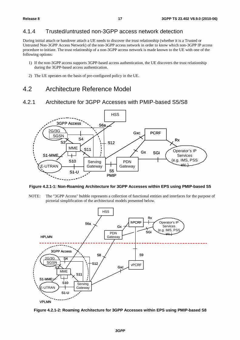
4.2 Architecture Reference Model
4.2.1 Architecture for 3GPP Accesses with PMIP-based S5/S8
SGi
PCRF
Gx
S6a
HSS
Operator's IP Services
(e.g. IMS, PSS etc.)
S1-U
S1-MME
E-UTRAN
2G/3G
S4S3
S5 PMIP
Rx
PDN Gateway
MME S11
S10
Gxc
Serving Gateway
3GPP Access
S12
SGSN
SGi
PCRF
Gx
S6a
HSS
Operator's IP Services
(e.g. IMS, PSS etc.)
S1-U
S1-MME
E-UTRAN
2G/3G
S4S3
S5 PMIP
Rx
PDN Gateway
MME S11
S10
Gxc
Serving Gateway
3GPP Access
S12
SGSN
Figure 4.2.1-1: Non-Roaming Architecture for 3GPP Accesses within EPS using PMIP-based S5
NOTE: The "3GPP Access" bubble represents a collection of functional entities and interfaces for the purpose of pictorial simplification of the architectural models presented below.
hPCRFS6a
HSS
PDNGatewayHPLMN
VPLMN
S8
vPCRF
S1-U
S1-MME
E-UTRAN
2G/3G S4
S3MME
S11
S10
Gxc
S9
SGiGx
Operator's IP Services
(e.g. IMS, PSS etc.)
Rx
3GPP Access
ServingGateway
S12SGSN
hPCRFS6a
HSS
PDNGatewayHPLMN
VPLMN
S8
vPCRF
S1-U
S1-MME
E-UTRAN
2G/3G S4
S3MME
S11
S10
Gxc
S9
SGiGx
Operator's IP Services
(e.g. IMS, PSS etc.)
Rx
3GPP Access
ServingGateway
S12SGSN
Figure 4.2.1-2: Roaming Architecture for 3GPP Accesses within EPS using PMIP-based S8
3GPP
3GPP TS 23.402 V8.9.0 (2010-06) 18Release 8
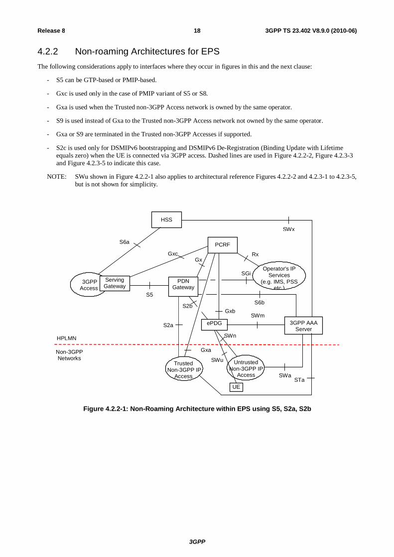
4.2.2 Non-roaming Architectures for EPS The following considerations apply to interfaces where they occur in figures in this and the next clause:
- S5 can be GTP-based or PMIP-based.
- Gxc is used only in the case of PMIP variant of S5 or S8.
- Gxa is used when the Trusted non-3GPP Access network is owned by the same operator.
- S9 is used instead of Gxa to the Trusted non-3GPP Access network not owned by the same operator.
- Gxa or S9 are terminated in the Trusted non-3GPP Accesses if supported.
- S2c is used only for DSMIPv6 bootstrapping and DSMIPv6 De-Registration (Binding Update with Lifetime equals zero) when the UE is connected via 3GPP access. Dashed lines are used in Figure 4.2.2-2, Figure 4.2.3-3 and Figure 4.2.3-5 to indicate this case.
NOTE: SWu shown in Figure 4.2.2-1 also applies to architectural reference Figures 4.2.2-2 and 4.2.3-1 to 4.2.3-5, but is not shown for simplicity.
SGi
PCRF
Gx
HSS
S2b
SWn
Operator's IP Services
(e.g. IMS, PSS etc.)
SWm
SWx
Untrusted Non-3GPP IP
Access SWa
HPLMN
Non-3GPP Networks
S6b
Rx
PDN Gateway
ePDG 3GPP AAA Server
Gxb
S2a
Gxa
Trusted Non-3GPP IP
Access STa
Gxc
S5
S6a
3GPP Access
Serving Gateway
UE
SWu
Figure 4.2.2-1: Non-Roaming Architecture within EPS using S5, S2a, S2b

3GPP
3GPP TS 23.402 V8.9.0 (2010-06) 19Release 8
SGi
PCRF
Gx
HSS
SWn
Operator's IP Services (e.g. IMS, PSS, etc.)
SWm
SWx
Untrusted Non - 3GPP IP
Access SWa
HPLMN
Non-3GPP Networks
S6b
Rx
PDN Gateway
Trusted Non-3GPP IP Access
STa
S2c S2c
ePDG 3GPP AAA Server
UE
Gxa
Gxb
Gxc
S5
S6a
S2c
3GPP Access
Serving Gateway
Figure 4.2.2-2: Non-Roaming Architecture within EPS using S5, S2c

3GPP
3GPP TS 23.402 V8.9.0 (2010-06) 20Release 8
4.2.3 Roaming Architectures for EPS
hPCRF
HSS
Trusted Non-3GPP IP
Access
PDN Gateway HPLMN
SWd
Non-3GPP Networks
VPLMN
vPCRF
3GPP AAA Proxy
STa
3GPP AAA Server
S2a
Gxa
S9
SGi Gx
S6b
Operator's IP Services
(e.g. IMS, PSS etc.)
Rx SWx
SWn
ePDG
SWa
Untrusted Non-3GPP IP
Access
SWm
S2b
Gxb Gxc
S8
S6a
3GPP Access
Serving Gateway
Figure 4.2.3-1: Roaming Architecture for EPS using S8, S2a– S2b - Home Routed
3GPP
3GPP TS 23.402 V8.9.0 (2010-06) 21Release 8
hPCRF
S6a
HSS
Trusted
Non - 3GPP IP Access
PDN
Gateway HPLMN
SWd
Non - 3GPP Networks
VPLMN
S8 vPCRF
3GPP
Access Serving
Gateway** 3GPP AAA
Proxy
STa
3GPP AAA
Server
S2a - PMIP
Gxc
Gxa
S6b
Operator's IP Services
(e.g. IMS, PSS etc.)
Rx SWx
ePDG S2b
SWm
Wn*
Un trusted
Non - 3GPP IP Access SWa
Gxb
SGi
Gx
S9
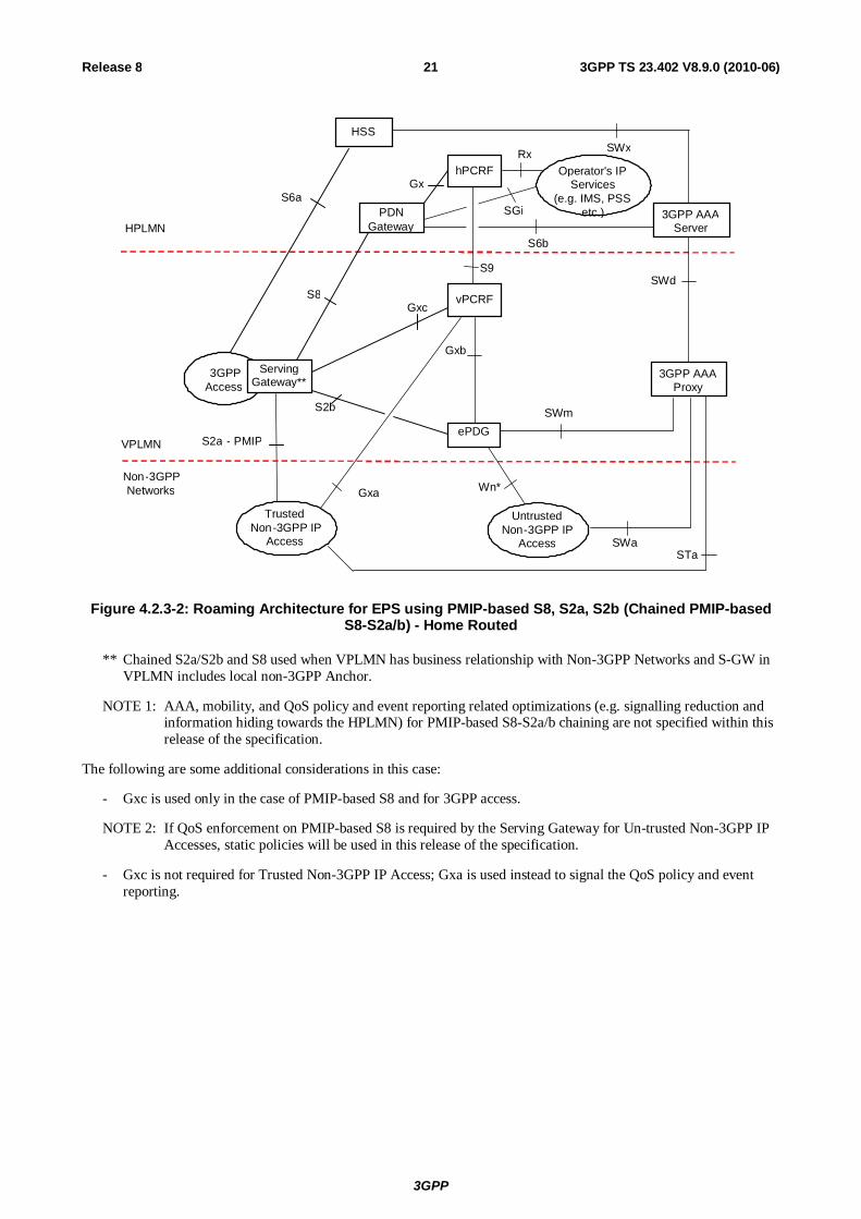
Figure 4.2.3-2: Roaming Architecture for EPS using PMIP-based S8, S2a, S2b (Chained PMIP-based S8-S2a/b) - Home Routed
** Chained S2a/S2b and S8 used when VPLMN has business relationship with Non-3GPP Networks and S-GW in VPLMN includes local non-3GPP Anchor.
NOTE 1: AAA, mobility, and QoS policy and event reporting related optimizations (e.g. signalling reduction and information hiding towards the HPLMN) for PMIP-based S8-S2a/b chaining are not specified within this release of the specification.
The following are some additional considerations in this case:
- Gxc is used only in the case of PMIP-based S8 and for 3GPP access.
NOTE 2: If QoS enforcement on PMIP-based S8 is required by the Serving Gateway for Un-trusted Non-3GPP IP Accesses, static policies will be used in this release of the specification.
- Gxc is not required for Trusted Non-3GPP IP Access; Gxa is used instead to signal the QoS policy and event reporting.

3GPP
3GPP TS 23.402 V8.9.0 (2010-06) 22Release 8
hPCRF
HSS
SWn
Operator's IP Services
(e.g. IMS, PSS etc.)
Trusted Non-3GPP IP
Access SWa
HPLMN
SWd
Non- 3GPP Networks
VPLMN
vPCRF
ePDG
SWm
Untrusted Non- 3GPP IP
Access STa
3GPP AAA Server
S2c
S2c
S9
SGi
Gx Rx
S6b
UE
3GPP AAA Proxy
SWx
Gxa
Gxb Gxc
S8
S6a
S2c
3GPP Access
Serving Gateway
PDN Gateway
Figure 4.2.3-3: Roaming Architecture for EPS using S8 – S2c - Home Routed

3GPP
3GPP TS 23.402 V8.9.0 (2010-06) 23Release 8
hPCRF
HSS
Trusted Non-3GPP IP
Access
HPLMN
SWd
Non-3GPP Networks
S6b
VPLMN
vPCRF
PDN Gateway
3GPP AAA Proxy
3GPP AAA Server
Gxa
S9
S2a
Gx
Rx
SGi
SWx
STa
Visited network IP services or proxies to home network services or PDN
Rx
Gxb
ePDG S2b
SWn
SWm
Untrusted Non-3GPP IP
Access SWa
S5
Gxc
S6a Operator's IP Services
(e.g. IMS, PSS etc.)
3GPP Access
Serving Gateway
Figure 4.2.3-4: Roaming Architecture for EPS using S5, S2a, S2b – Local Breakout
NOTE 2: The two Rx instances in Figure 4.2.3-4 apply to different application functions in the HPLMN and VPLMN.

3GPP
3GPP TS 23.402 V8.9.0 (2010-06) 24Release 8
hPCRF
HSS
SWn
Trusted Non - 3GPP IP Access SWa
HPLMN
SWd
Non - 3GPP Networks
S6b
VPLMN
vPCRF
PDN G ateway 3GPP AAA Proxy
e PDG
SWm
U ntrusted N on - 3GPP IP Access
STa
3GPP AAA Server
S9
Gx
S2c S2c U E
Rx
SGi
SWx
V isited network IP s ervices or proxies to ho m e network services or PDN
R x
Gxa
Gxb
S5
G xc
S6a
Operator's IP Services ( e.g. IMS, PSS
etc.)
S2c
3GPP Access
Serving Gateway
Figure 4.2.3-5: Roaming Architecture for EPS using S5, S2c – Local Breakout
NOTE 3: The two Rx instances in Figure 4.2.3-5 apply to different application functions in the HPLMN and VPLMN.
4.3 Network Elements
4.3.1 Access Networks
4.3.1.1 E-UTRAN
E-UTRAN is described in detail in TS 36.300 [6] with additional functions listed in TS 23.401 [4].
4.3.1.2 Trusted and Untrusted Non-3GPP Access Network
Trusted and Untrusted Non-3GPP Access Networks are IP access networks that use access technology whose specification is out of the scope of 3GPP.
Whether a Non-3GPP IP access network is Trusted or Untrusted is not a characteristic of the access network.
In non-roaming scenario it is the HPLMN's operator decision if a Non-3GPP IP access network is used as Trusted or Untrusted Non-3GPP Access Network.
In roaming scenario, the HSS/3GPP AAA Server in HPLMN makes the final decision of whether a Non-3GPP IP access network is used as Trusted or Untrusted non-3GPP Access Network. The HSS/3GPP AAA Server may take the VPLMN's policy and capability returned from the 3GPP AAA Proxy or roaming agreement into account.

3GPP
3GPP TS 23.402 V8.9.0 (2010-06) 25Release 8
For supporting multiple PDNs, the same trust relationship shall apply to all the PDNs the UE connects to from a certain Non-3GPP Access Network, i.e. it shall not be possible to access one PDN using the non-3GPP access network as Trusted, while access to another PDN using the same non-3GPP access network as Untrusted.
4.3.2 MME The details of functionality of MME are described TS 23.401 [4].
The following are additional MME functions:
- HRPD access node (terminating S101 reference point) selection and maintenance for handovers to HRPD;
- Transparent transfer of HRPD signalling messages and transfer of status information between E-UTRAN and HRPD access, as specified in the pre-registration and handover flows.
- Forwarding the GRE key for uplink traffic to the target S-GW in case of CN node relocation.
4.3.3 Gateway
4.3.3.1 General
Two logical Gateways exist:
- Serving GW (S-GW)
- PDN GW (P-GW)
The functional split of PDN GW and Serving GW is described in TS 23.401 [4].
4.3.3.2 Serving GW
The functionality of the Serving GW is described in TS 23.401 [4]. In addition to the functions described in TS 23.401 [4] the Serving GW includes the following functionality:
- A local non-3GPP anchor for the case of roaming when the non-3GPP IP accesses connected to the VPLMN.
- Event reporting (change of RAT, etc.) to the PCRF.
- Uplink and downlink bearer binding towards 3GPP accesses as defined in TS 23.203 [19].
- Uplink bearer binding verification with packet dropping of "misbehaving UL traffic".
NOTE 1: The term 'Uplink bearer binding verification' is defined in TS 23.401 [4].
- Mobile Access Gateway (MAG) according to PMIPv6 specification, RFC 5213 [8], if PMIP-based S5 or S8 is used. The MAG function shall be able to send UL packets before sending the PBU or before receiving the PBA.
- Decide if packets are to be forwarded (uplink towards PDN or downlink towards UE) or if they are locally destined to the S-GW (e.g. Router Solicitation).
- DHCPv4 (relay agent) and DHCPv6 (relay agent) functions if PMIP-based S5 or S8 is used.
- Handling of Router Solicitation and Router Advertisement messages as defined in RFC 4861 [38], if PMIP based S5 and S8 is used.
- Handling of Neighbour Solicitation and Neighbor Advertisement messages as defined in RFC 4861 [38], if PMIP based S5 and S8 is used.
- Allocation of GRE key, which is used by the PDN GW to encapsulate downlink traffic to the Serving GW on the PMIP-based S5/S8 interface.
- If PMIP-based S8-S2a/b chaining is used:
- the Serving GW acts as a LMA towards the MAG function of the Trusted Non-3GPP IP Access or the ePDG;

3GPP
3GPP TS 23.402 V8.9.0 (2010-06) 26Release 8
- the Serving GW allocates GRE key, which is used to encapsulate uplink traffic on PMIPv6-based S2a/S2b interface.
NOTE 2: The Serving GW does not require full MAG and full LMA functionally.
- the Serving GW includes functionality to interwork the PMIPv6 signalling towards the PDN GW and PMIPv6 signalling towards the MAG function of the Trusted Non-3GPP IP Access or the ePDG. In this case the Serving GW also acts as a MAG towards the PDN GW;
- the Serving GW includes functionality to link the user-plane of the PMIPv6 tunnel towards the PDN GW and the user-plane of the PMIPv6 tunnel towards the MAG function of the Trusted Non-3GPP IP Access or the ePDG.
4.3.3.3 PDN GW
PDN GW functionality is described in TS 23.401 [4] for 3GPP accesses connected to the EPC via GTP-based and PMIP-based S5/S8 interface. The PDN GW supports functionality specified in TS 23.401 [4] that is common to both PMIP-based and GTP-based S5/S8 interfaces also for access to EPC via non-3GPP accesses.
Additionally, the PDN GW is the user plane anchor for mobility between 3GPP access and non-3GPP access. For this, the PDN GW includes the following functionality:
- A LMA according to the PMIPv6 specification, RFC 5213 [8], if PMIP-based S5 or S8, or if S2a or S2b is used. The LMA function shall be able to accept UL packets from any trusted MAG without enforcing that the source IP address must match the CoA in the MN BCE.
- A DSMIPv6 Home Agent, as described in RFC 5555 [10], if S2c is used.
- Allocation of GRE key, which is used to encapsulate uplink traffic to the PDN GW on the PMIP-based S5/S8, or S2a or S2b interface.
- A MIPV4 Home Agent, if S2a with MIPv4 FA CoA mode is used.
4.3.4 ePDG The functionality of ePDG includes the following:
- Functionality defined for the PDG in TS 23.234 [7] for the allocation of a remote IP address as an IP address local to the ePDG which is used as CoA when S2c is used;
- Functionality for transportation of a remote IP address as an IP address specific to a PDN when S2b is used;
- Routing of packets from/to PDN GW (and from/to Serving GW if it is used as local anchor in VPLMN) to/from UE;
- De-capsulation/Encapsulation of packets for IPSec and PMIPv6 tunnels (the latter only if network based mobility (S2b) is used);
- Mobile Access Gateway (MAG) according to the PMIPv6 specification, RFC 5213 [8], if network based mobility (S2b) is used;
- Tunnel authentication and authorization (termination of IKEv2 signalling and relay via AAA messages);
- Local mobility anchor within untrusted non-3GPP access networks using MOBIKE (if needed);
- Transport level packet marking in the uplink;
- Enforcement of QoS policies based on information received via AAA infrastructure;
- Lawful Interception.
- Allocation of GRE key, which is used to encapsulate downlink traffic to the ePDG on the PMIPv6-based S2b interface.

3GPP
3GPP TS 23.402 V8.9.0 (2010-06) 27Release 8
4.3.5 PCRF The functionality of PCRF is described in TS 23.203 [19] with additional functionality listed in TS 23.401 [4]. In the non-roaming scenario, additionally, the PCRF terminates the Gxa, Gxb and Gxc reference points with the appropriate IP-CANs.
In roaming scenarios, the difference from TS 23.401 [4], is that the vPCRF exists for the UE for the scenario of roaming with home-routed traffic in addition to the scenario in TS 23.401 [4] of roaming with local breakout.
4.3.5.1 Home PCRF
In addition to the h-PCRF functionality listed in TS 23.401 [4], in this document the Home PCRF
- Terminates the Gx reference point for roaming with home routed traffic;
- Terminates the Gxa, Gxb or Gxc/S9 reference points as appropriate for the IP-CAN type.
4.3.5.2 Visited PCRF
In addition to the v-PCRF functionality listed in TS 23.401 [4], in this document the Visited PCRF
- Terminates the Gxa, Gxb or Gxc reference points as appropriate for the IP-CAN type;
- Terminates the S9 reference point.
4.4 Reference Points
4.4.1 List of Reference Points The description of the reference points:
S1-MME, S1-U, S3, S4, S10, S11: these are defined in TS 23.401 [4].
S2a It provides the user plane with related control and mobility support between trusted non 3GPP IP access and the Gateway.
S2b It provides the user plane with related control and mobility support between ePDG and the Gateway.
S2c It provides the user plane with related control and mobility support between UE and the Gateway. This reference point is implemented over trusted and/or untrusted non-3GPP Access and/or 3GPP access.
S5 It provides user plane tunnelling and tunnel management between Serving GW and PDN GW. It is used for Serving GW relocation due to UE mobility and in case the Serving GW needs to connect to a non collocated PDN GW for the required PDN connectivity.
S6a This interface is defined between MME and HSS for authentication and authorization. It is defined in TS 23.401 [4].
S6b It is the reference point between PDN Gateway and 3GPP AAA server/proxy for mobility related authentication if needed. This reference point may also be used to retrieve and request storage of mobility parameters. This reference point may also be used to retrieve static QoS profile for a UE for non-3GPP access in case dynamic PCC is not supported.
Gx It provides transfer of (QoS) policy and charging rules from PCRF to Policy and Charging Enforcement Function (PCEF) in the PDN GW.
Gxa It provides transfer of (QoS) policy information from PCRF to the Trusted Non-3GPP accesses.
Gxb This interface is not specified within this release of the specification.
Gxc It provides transfer of (QoS) policy information from PCRF to the Serving Gateway

3GPP
3GPP TS 23.402 V8.9.0 (2010-06) 28Release 8
PMIP-based S8 It is the roaming interface in case of roaming with home routed traffic. It provides the user plane with related control between Gateways in the VPLMN and HPLMN.
S9 It provides transfer of (QoS) policy and charging control information between the Home PCRF and the Visited PCRF in order to support local breakout function. In all other roaming scenarios, S9 has functionality to provide dynamic QoS control policies from the HPLMN.
SGi It is the reference point between the PDN Gateway and the packet data network. Packet data network may be an operator external public or private packet data network or an intra operator packet data network, e.g. for provision of IMS services. This reference point corresponds to Gi and Wi functionalities and supports any 3GPP and non-3GPP access systems.
SWa It connects the Untrusted non-3GPP IP Access with the 3GPP AAA Server/Proxy and transports access authentication, authorization and charging-related information in a secure manner.
STa It connects the Trusted non-3GPP IP Access with the 3GPP AAA Server/Proxy and transports access authentication, authorization, mobility parameters and charging-related information in a secure manner.
SWd It connects the 3GPP AAA Proxy, possibly via intermediate networks, to the 3GPP AAA Server.
SWm This reference point is located between 3GPP AAA Server/Proxy and ePDG and is used for AAA signalling (transport of mobility parameters, tunnel authentication and authorization data). This reference point also includes the MAG-AAA interface functionality, IETF Internet-Draft, draft-ietf-dime-pmip6-01 [43] and Mobile IPv6 NAS-AAA interface functionality, RFC 5447 [44].
SWn This is the reference point between the Untrusted Non-3GPP IP Access and the ePDG. Traffic on this interface for a UE-initiated tunnel has to be forced towards ePDG. This reference point has the same functionality as Wn which is defined in TS 23.234 [5].
SWu This is the reference point between the UE and the ePDG and supports handling of IPSec tunnels. The functionality of SWu includes UE-initiated tunnel establishment, user data packet transmission within the IPSec tunnel and tear down of the tunnel and support for fast update of IPSec tunnels during handover between two untrusted non-3GPP IP accesses.
SWx This reference point is located between 3GPP AAA Server and HSS and is used for transport of authentication, subscription and PDN connection related data.
S1 interface for E-UTRAN is the same for both the architectures.
Protocol assumption:
- S2a interface and S2b interface are based on current or future IETF RFCs. S2a is based on Proxy Mobile IP version 6. To enable access via Trusted Non 3GPP IP accesses that do not support PMIPv6, S2a also supports Client Mobile IPv4 FA mode. S2b is based on Proxy Mobile IP version 6.
- S2c is based on DSMIPv6 [10].
- The PMIP-based S5, PMIP-based S8 and S2a/S2b interfaces are based on the same protocols and differences shall be minimized. The S5 interface is based on the PMIPv6 specification, RFC 5213 [8]. The GTP variant of S5 interface is described in TS 23.401 [4].
- PMIPv6-based S8 interface is based on the PMIPv6 specification, RFC 5213 [8]. The GTP variant interface is described in TS 23.401 [4].
- The PMIPv6-based interfaces (S5, S8, S2a, and S2b) shall support Generic Routing Encapsulation (GRE) RFC 2784 [23] including the Key field extension RFC 2890 [24]. The Key field value of each GRE packet header should enable the unique identification of the UE PDN connection that the GRE packet payload is associated with. These keys are exchanged using GRE Options extension to PMIPv6 Proxy Binding Update and Proxy Binding Ack messages on PMIPv6-based interfaces, which is described in draft-ietf-netlmm-grekey-option-01 [36].
- In case of CN node relocation, the GRE key for uplink traffic is forwarded to the target S-GW over S10/S11 reference point.
- SWu interface is based on IKEv2 [9] and MOBIKE [18].

3GPP
3GPP TS 23.402 V8.9.0 (2010-06) 29Release 8
The EPS shall allow the operator to configure a type of access (3GPP or non-3GPP) as the "home link" for Client Mobile IP purposes.
NOTE: Redundancy support on reference points PMIP-based S5 and PMIP-based S8 should be taken into account.
4.4.2 Reference Point Requirements
4.4.2.1 S5 Reference Point Requirements
Both the GTP and PMIP variants of the S5 reference point shall satisfy the following architectural principles:
- There shall be only one radio interface protocol stack defined, common for both S5 variants, including both radio layer and Non-Access Stratum protocols.
- There shall be only one S6a interface defined common to both S5 variants. There may be a need for different information elements specific to PMIP-based or GTP-based variants of S5 but differences due to the S5 variants should be minimized.
- In the non-roaming case, there shall be only one Gx interface defined for transfer of policy and charging rules, common to both S5 variants. There may be a need for different information elements specific to PMIP-based or GTP-based variants of S5 but differences due to the S5 variants should be minimized.
- Differences between S5 variants in terms of functional split between the endpoints should be minimized.
The S5 reference point shall fulfil the following requirements:
- S5 shall allow access to multiple PDNs. It shall be possible to allow an UE to connect to different packet data networks. It shall also be possible to support a UE with concurrent connections to several packet data networks.
- S5 shall be able to transport both IPv4 and IPv6 user plane traffic independent of IP version of the underlying IP transport network.
- S5 shall support fault handling. There should be mechanisms to identify and signal faults for groups of mobiles – e.g., if a large node handling millions of terminals goes down.
NOTE: As further development of the architecture takes place as well as when additional functionality such as MBMS, LCS etc. are addressed, further requirements will be needed.
4.4.2.2 Void
4.4.2.3 Void
4.4.2.4 Void
4.5 High Level Functions
4.5.1 PDN GW Selection Function for Non-3GPP Accesses for S2a and S2b
PDN Gateway selection for non-3GPP accesses uses similar mechanisms as defined in TS 23.401 [4], with the following modification:

3GPP
3GPP TS 23.402 V8.9.0 (2010-06) 30Release 8
- The PDN Gateway selection function interacts with the 3GPP AAA Server or 3GPP AAA Proxy and uses subscriber information provided by the HSS to the 3GPP AAA Server. To support separate PDN GW addresses at a PDN GW for different mobility protocols (PMIP, MIPv4 or GTP), the PDN GW Selection function takes mobility protocol type into account when deriving PDN GW address by using the Domain Name Service function.
During the initial authorization, PDN Gateway selection information for each of the subscribed PDNs is returned to the non-3GPP access system. The PDN Gateway selection information includes:
- The PDN GW identity, which is a logical name (FQDN) or IP address and an APN; or
- an APN and an indication whether the allocation of a PDN GW from the visited PLMN is allowed or a PDN GW from the home PLMN shall be allocated.
This enables the entity requiring the IP address of the PDN Gateway to proceed with selection as per the procedures defined in TS 23.401 [4], clause 4.3.8.1. Once the selection has occurred, the PDN Gateway registers its association with a UE and the APN with the AAA/HSS by sending PDN GW identity, that is either its IP address (e.g. if it has a single IP address for all the mobility protocols it supports or if it only supports one mobility protocol) or its FQDN (e.g. if it has multiple IP addresses for the mobility protocols it supports), as well as information that identifies the PLMN in which the PDN GW is located to the 3GPP AAA Server or AAA Proxy only when the Access Technology Type is non-3GPP. For 3GPP access types, the MME/SGSN updates the HSS with the selected PDN GW identity, as well as information that identifies the PLMN in which the PDN GW is located, as per TS 23.401 [4]. This permits the HSS and 3GPP AAA Server or Proxy to provide the association of the PDN Gateway identity and the related APN for the UE subsequently.
NOTE 1: The format of the information that identifies the PLMN in which the PDN GW is located is defined in stage 3 specifications.
In the case that a UE already has assigned PDN Gateway(s), the PDN GW identity for each of the already allocated PDN Gateway(s), as well as information that identifies the PLMN in which the PDN GW is located, are returned by the 3GPP AAA Server or Proxy during the authorization step. This eliminates the need to repeat PDN Gateway selection for the PDNs the UE is already connected with. The information about the PLMN in which the PGW is located allows the receiving entity to determine an appropriate APN-OI.
Upon mobility between 3GPP and non-3GPP accesses, PDN Gateway selection information for the subscribed PDNs the UE is not yet connected with is returned to the target access system as done during initial attachment. For the PDNs the UE is already connected with transfer of PDN GW information takes place as defined below:
- If a UE attaches to a non-3GPP access and it already has assigned PDN Gateway(s) due to a previous attach in a 3GPP access, the HSS provides the PDN GW identity, as well as information that identifies the PLMN in which the PDN GW is located, for each of the already allocated PDN Gateway(s) with the corresponding PDN information to the 3GPP AAA server over the SWx reference point.
- If a UE attaches to a 3GPP access and it already has an assigned PDN Gateway(s) due to a previous attach in a non-3GPP access, the HSS provides the PDN GW identity, as well as information that identifies the PLMN in which the PDN GW is located, for each of the already allocated PDN Gateway(s) with the corresponding PDN information to the MME over the S6a reference point.
The HSS receives the PDN GW identity for each of the selected PDN GWs and the corresponding PDN information for a given UE, from both the 3GPP AAA Server and also from the MME, depending on the currently in-use access. The HSS is responsible for the storage of the selected PDN GW identity as described in clause 12.
NOTE 2: The location of the PDN GW selection function depends upon the type of S2 interface used for attachment and the IP mobility mechanism being used.
- For PMIPv6 on S2a/b, the entity requesting the PDN Gateway is the entity acting as Mobile Access Gateway (MAG).
- For the S8-S2a/b chained cases, the PDN GW information is sent together with the selected Serving GW address from the 3GPP AAA proxy to the entity acting as MAG in the non-3GPP access network during access authentication and authorization. The PDN GW selection mechanism is the same as in the unchained case. The MAG function of the non-3GPP access network conveys the PDN GW address to the Serving GW as part of the PMIPv6 PBU message.
- For MIPv4 FA mode on S2a, the entity requesting the PDN Gateway is the entity that plays the role of the FA.
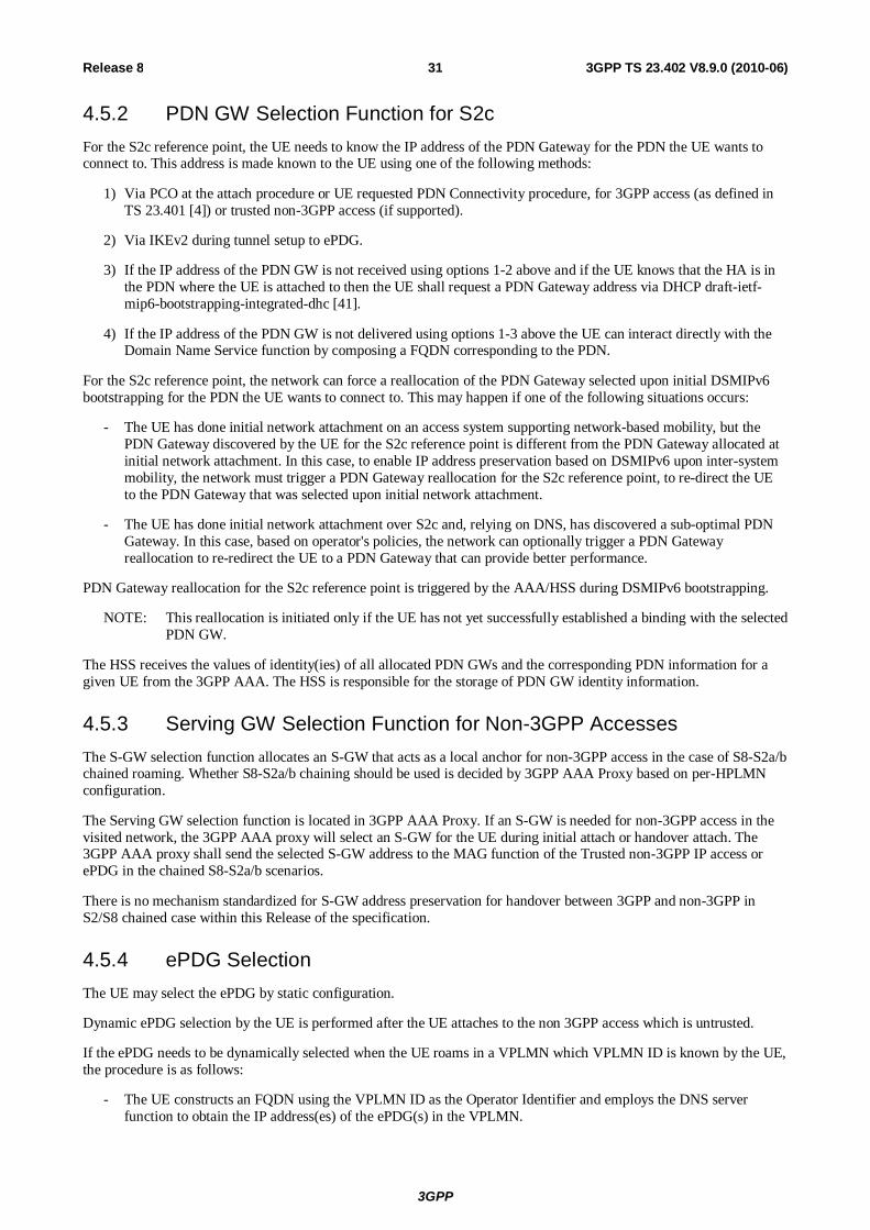
3GPP
3GPP TS 23.402 V8.9.0 (2010-06) 31Release 8
4.5.2 PDN GW Selection Function for S2c For the S2c reference point, the UE needs to know the IP address of the PDN Gateway for the PDN the UE wants to connect to. This address is made known to the UE using one of the following methods:
1) Via PCO at the attach procedure or UE requested PDN Connectivity procedure, for 3GPP access (as defined in TS 23.401 [4]) or trusted non-3GPP access (if supported).
2) Via IKEv2 during tunnel setup to ePDG.
3) If the IP address of the PDN GW is not received using options 1-2 above and if the UE knows that the HA is in the PDN where the UE is attached to then the UE shall request a PDN Gateway address via DHCP draft-ietf-mip6-bootstrapping-integrated-dhc [41].
4) If the IP address of the PDN GW is not delivered using options 1-3 above the UE can interact directly with the Domain Name Service function by composing a FQDN corresponding to the PDN.
For the S2c reference point, the network can force a reallocation of the PDN Gateway selected upon initial DSMIPv6 bootstrapping for the PDN the UE wants to connect to. This may happen if one of the following situations occurs:
- The UE has done initial network attachment on an access system supporting network-based mobility, but the PDN Gateway discovered by the UE for the S2c reference point is different from the PDN Gateway allocated at initial network attachment. In this case, to enable IP address preservation based on DSMIPv6 upon inter-system mobility, the network must trigger a PDN Gateway reallocation for the S2c reference point, to re-direct the UE to the PDN Gateway that was selected upon initial network attachment.
- The UE has done initial network attachment over S2c and, relying on DNS, has discovered a sub-optimal PDN Gateway. In this case, based on operator's policies, the network can optionally trigger a PDN Gateway reallocation to re-redirect the UE to a PDN Gateway that can provide better performance.
PDN Gateway reallocation for the S2c reference point is triggered by the AAA/HSS during DSMIPv6 bootstrapping.
NOTE: This reallocation is initiated only if the UE has not yet successfully established a binding with the selected PDN GW.
The HSS receives the values of identity(ies) of all allocated PDN GWs and the corresponding PDN information for a given UE from the 3GPP AAA. The HSS is responsible for the storage of PDN GW identity information.
4.5.3 Serving GW Selection Function for Non-3GPP Accesses The S-GW selection function allocates an S-GW that acts as a local anchor for non-3GPP access in the case of S8-S2a/b chained roaming. Whether S8-S2a/b chaining should be used is decided by 3GPP AAA Proxy based on per-HPLMN configuration.
The Serving GW selection function is located in 3GPP AAA Proxy. If an S-GW is needed for non-3GPP access in the visited network, the 3GPP AAA proxy will select an S-GW for the UE during initial attach or handover attach. The 3GPP AAA proxy shall send the selected S-GW address to the MAG function of the Trusted non-3GPP IP access or ePDG in the chained S8-S2a/b scenarios.
There is no mechanism standardized for S-GW address preservation for handover between 3GPP and non-3GPP in S2/S8 chained case within this Release of the specification.
4.5.4 ePDG Selection The UE may select the ePDG by static configuration.
Dynamic ePDG selection by the UE is performed after the UE attaches to the non 3GPP access which is untrusted.
If the ePDG needs to be dynamically selected when the UE roams in a VPLMN which VPLMN ID is known by the UE, the procedure is as follows:
- The UE constructs an FQDN using the VPLMN ID as the Operator Identifier and employs the DNS server function to obtain the IP address(es) of the ePDG(s) in the VPLMN.

3GPP
3GPP TS 23.402 V8.9.0 (2010-06) 32Release 8
- The UE selects an ePDG address from the list returned in the DNS response and initiates the IPsec tunnel establishment.
Otherwise if the ePDG needs to be dynamically selected the procedure is as follows:
- The UE constructs an FQDN using the HPLMN ID and employs the DNS server function to obtain the IP address(es) of the ePDG(s).
- The UE selects an ePDG address from the list returned in the DNS response and initiates the IPsec tunnel establishment.
A UE connected to one or multiple PDN GWs uses a single ePDG. In case of handover between ePDGs, the UE may be temporarily connected to two ePDGs.
4.5.5 PCRF Selection In addition to the PDN-GW and AF being served by one or more PCRF nodes in a HPLMN and, where applicable , in VPLMN as in TS 23.401 [4], the following nodes in this specification also are served by PCRF:
- Serving GW;
- Elements in trusted non-3gpp access;
- ePDG.
Selection of a PCRF by nodes served by PCRF in this specification, is the same as that in specified in TS 23.203 [19].
4.5.6 DSMIPv6 Home Link Detection Function The DSMIPv6 Home Link Detection Function is used by the UE to detect if, for a specific PDN, an access interface is the Home Link from a DSMIPv6 perspective.
It is up to the UE configuration to decide when to trigger the home link detection function for a specific PDN connection, except that homelink detection for an access interface shall be performed before sending any DSMIPv6 Binding Update via that access interface.
The UE detects the home link comparing the IPv6 prefix associated with a specific access system of the UE , and the Home Network Prefix (HNP) associated with the PDN connection. If there is a match, the UE detects it is in the home link for this specific PDN over the access interface. Otherwise, the UE detects it is not in the home link for this specific PDN over the access interface.
Home Network Prefix (HNP) may be assigned in a 3GPP access via PCO during 3GPP attach, if supported by the UE, or via IKEv2.
NOTE: The UE knows the IPv6 prefix associated with a specific access system interface via IP address allocation mechanisms applied in that access system.
The UE knows the HNP associated with a specific PDN from the IPsec security association bootstrap (see clause 6.3, step 4) or from PCO received in 3GPP attach.
4.6 Identities
4.6.1 User Identification In order to access the 3GPP Evolved Packet Core from non-3GPP accesses, and get Authentication, Authorization and Accounting services from the Evolved Packet Core, the NAI RFC 4282 [15] based user identification defined in TS 23.003 [16] shall be used.
In order to support network-based and client-based mobility related services from the evolved packet core, the NAI RFC 4282 [15] based user identification as defined in TS 23.003 [16] shall be used by the network and mobility clients. The username part of NAI shall be based on IMSI. This applies to S2a, S2b and S2c reference points.

3GPP
3GPP TS 23.402 V8.9.0 (2010-06) 33Release 8
User identification in non-3GPP accesses may require additional identities that are out of the scope of 3GPP. These user identities, if not compliant to TS 23.003 [16], are however not sufficient to identify a user in the 3GPP Evolved Packet Core.
4.7 IP Address Allocation
4.7.1 IP Address Allocation with PMIP-based S5/S8 The IP address allocation mechanisms described in clause 5.3.1.1 of TS 23.401 [4] are also valid for the PMIP based S5/S8. This clause is complementary to clause 5.3.1 of TS 23.401 [4] and describes the differences in the IP Address allocation when PMIP-based S5/S8 is used.
For IP address allocation with PMIP-based S5/S8, the following clarifications apply:
- If the PDN Type associated with the PDN connection is IPv4:
- If initial and handover attach and deferred IPv4 address allocation is not used, the IPv4 address is allocated via default bearer activation. This case does not present any architecture differences from the GTP based S5/S8 described in clause 5.3.1.2.1 of TS 23.401 [4]. In this case, the Serving GW shall request IPv4 address in the Proxy Binding Update. Then the IPv4 address is assigned by the PDN GW and returned to the Serving Gateway in the Proxy Binding Acknowledgement.
- If initial and handover attach and deferred IPv4 address allocation is used, the IPv4 address allocation and IPv4 parameter configuration via DHCPv4 according to RFC 2131 [28] and RFC 4039 [29] procedure does not present any architecture differences from the GTP based S5/S8 described in TS 23.401 [4], clause 5.3.1.2.4, except that the Serving GW shall have DHCPv4 relay agent functionality. The Serving GW shall request IPv4 address in the Proxy Binding Update. Then the IPv4 address is assigned by the PDN GW and returned to the Serving Gateway in the Proxy Binding Acknowledgement. The PDN GW shall also send the DHCPv4 Address Allocation Procedure Indication in the same Proxy Binding Acknowledgement message. In this case, the UE IPv4 address assigned by the PDN GW is not provided as part of the default bearer activation procedures to the UE. The Serving GW replaces the IPv4 address assigned by the PDN GW to 0.0.0.0 in the response message to the MME. The MME then forwards the 0.0.0.0 address to the UE. After the default bearer establishment procedure is completed, the UE uses the connectivity with the EPS and initiates the IPv4 address allocation on its own using DHCPv4 as specified in figure 4.7.1-1. The IPv4 address provided to the UE by DHCPv4 procedure shall correspond to the value provided in the Proxy Binding Acknowledgement message.
- If the IPv4 address is allocated by using DHCPv4 procedure, then at any time after the UE releases the IPv4 address using DHCPv4 or the IPv4 address lease time expires, the PDN GW initiates the "PDN-GW initiated PDN-disconnection" procedure for the given PDN connection. The same IPv4 address shall not be allocated to another UE immediately.
- If the PDN Type associated with the PDN connection is IPv6:
- IPv6 network prefix allocation via IPv6 Stateless Address auto-configuration: The IPv6 network prefix is assigned by the PDN GW and returned to the Serving Gateway in the Proxy Binding Acknowledgement. The Serving GW shall advertise the same information as the PDN GW would advertise with GTP based S5/S8. To ensure that link-local address generated by the UE does not collide with the link-local address of the Serving GW, the PDN GW shall provide an interface identifier to the UE and the UE shall use this interface identifier to configure its link-local address. For stateless address auto-configuration however, the UE can choose any interface identifier to generate IPv6 address, other than link-local, without involving the network. The PDN GW shall also provide a link-local address to the Serving GW and the Serving GW shall use the link-local address on the access link shared with the UE. In the case of PMIP-S5/S8 because any prefix that the Serving GW will advertise to the UE is unique, there is no need for the UE to perform Duplicate Address Detection for global uniqueness for any IPv6 address configured from the allocated IPv6 network prefix. However, the Serving GW shall respond with Neighbor Advertisement upon receiving Neighbor Solicitation messages from a given UE. For example, the UE may perform Neighbor Unreachability Detection towards the Serving GW, the Serving GW supports the DAD related functionality similar to that supported by PDN GW in the case of GTP based S5/S8 described in TS 23.401 [4], clause 5.3.1.2.2. Otherwise the PDN GW has the same functions as it is defined in TS 23.401 [4], clause 5.3.1.2.2.

3GPP
3GPP TS 23.402 V8.9.0 (2010-06) 34Release 8
- IPv6 parameter configuration via Stateless DHCPv6 procedure does not present any architecture differences from the GTP based S5/S8 described in TS 23.401 [4], clause 5.3.1.2.3, except that the Serving GW shall have DHCPv6 relay agent functionality. The P-GW notifies the UE with the same DNSv6 information as was provided via PCO during the PDN connection establishment procedure, e.g. Attach, if DHCPv6 procedure is performed by the UE.
- If sent, the router solicitation from the UE comes subsequent to the Attach procedure, as shown in Figure 4.7.1-2. The IPv6 network prefix assigned in the PMIP Binding Acknowledgement is sent in the Router Advertisement.
- If the PDN type associated with the PDN connection is IPv4v6:
- The IPv6 network prefix allocation via IPv6 Stateless Address auto-configuration procedure and IPv6 parameter configuration via Stateless DHCPv6 procedure are the same as for PDN type IPv6 defined in pervious bullets.
- If initial attach and deferred IPv4 address allocation is used, the Serving GW shall request both IPv6 network prefix and IPv4 address in the Proxy Binding Update. In this case no IPv4 address is assigned by the PDN GW during the attach procedure. Only IPv6 network prefix is returned to the Serving Gateway in the Proxy Binding Acknowledgement. The PDN GW shall also send the DHCPv4 Address Allocation Procedure Indication in the same PBA message. Then the Serving GW shall respond to the UE by setting the IPv4 PDN Address to 0.0.0.0. The UE may obtain an IPv4 address subsequently, by initiating DHCPv4 procedure as specified in figure 4.7.1-1.
- If initial attach and deferred IPv4 address allocation is not used, the Serving GW shall request both IPv6 network prefix and IPv4 address in the Proxy Binding Update. In this case IPv4 address is assigned by the PDN GW during the attach procedure. IPv6 network prefix and IPv4 address is returned to the Serving Gateway in the Proxy Binding Acknowledgement. The Serving GW shall deliver IPv4 address to the UE.
- For handover attach (i.e. Request Type set to "handover"), the Serving GW shall request both IPv6 network prefix and IPv4 address in the Proxy Binding Update. Irrespective of whether the UE requested deferred IPv4 address or not. The previously assigned IPv6 network prefix and/or IPv4 address are returned to the Serving Gateway in the Proxy Binding Acknowledgement during the handover attach procedure. If deferred IPv4 address allocation is used for this PDN connection, the PDN GW shall also send the DHCPv4 Address Allocation Procedure Indication in the same PBA message. In this case, the UE IPv4 address is not provided as part of the default bearer activation procedures to the UE. The Serving GW shall respond to the MME by setting the PDN Address to 0.0.0.0. The MME then forwards the 0.0.0.0 address to the UE. After the default bearer establishment procedure is completed, the UE uses the connectivity with the EPS and may renew the IPv4 address allocation using DHCPv4. The IPv4 Address provided to the UE by subsequent DHCPv4, when initiated by the UE, must correspond to the value provided in the PBA.
- If the IPv4 address is provided to the UE by using DHCPv4 procedure, then at any time after the UE releases the IPv4 address using DHCPv4 or IPv4 address lease time expires, the PDN GW initiates the "PDN Gateway initiated IPv4 address Delete" procedure to delete the IPv4 address from the PDN connection and bearer contexts. The same IPv4 address shall not be allocated to another UE immediately.
- If an external PDN Address Allocation is needed, the PDN GW follows the same procedures defined in TS 23.401 [4] to obtain the external IP address after the PBU is received and before the PBA is sent.
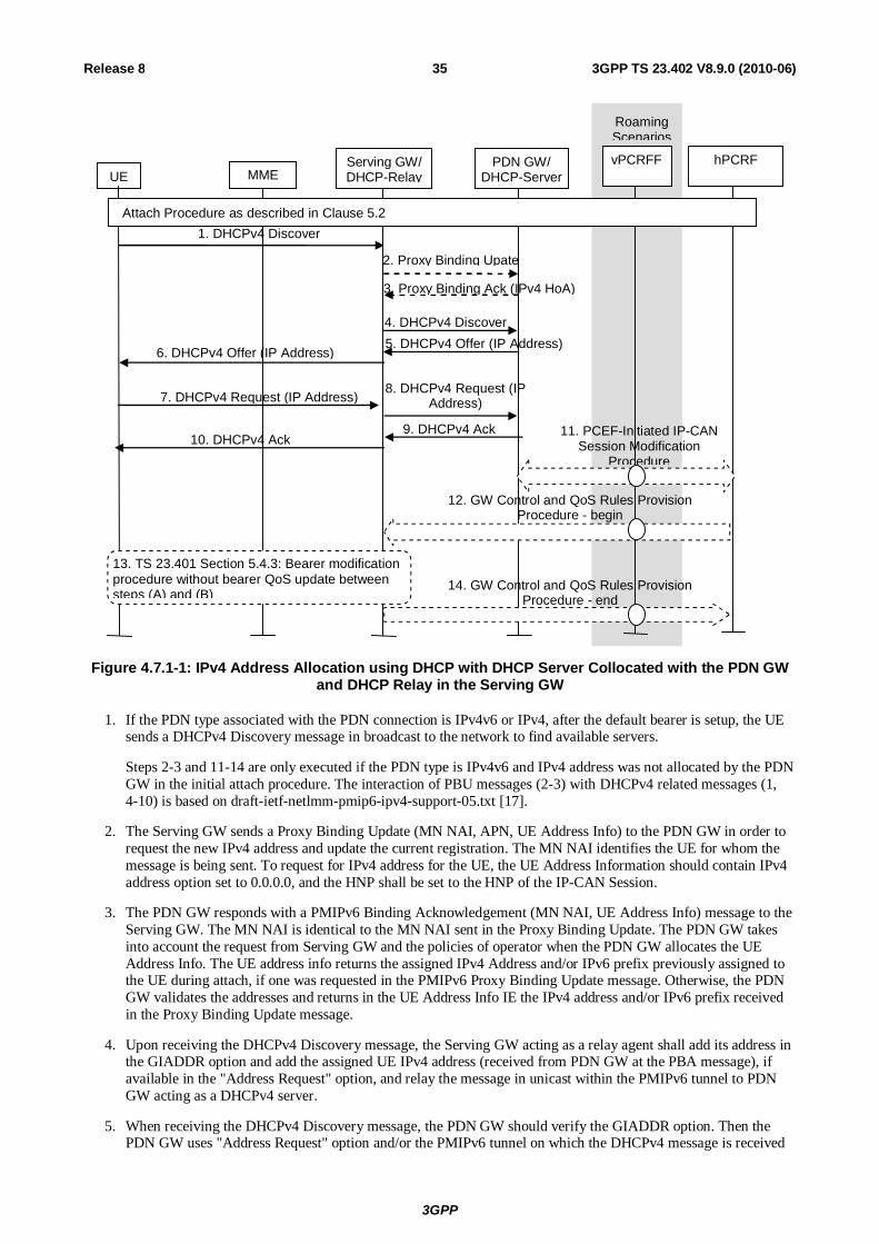
3GPP
3GPP TS 23.402 V8.9.0 (2010-06) 35Release 8
UE Serving GW/ DHCP-Relay MME
PDN GW/ DHCP-Server
1. DHCPv4 Discover
7. DHCPv4 Request (IP Address)
10. DHCPv4 Ack
4. DHCPv4 Discover 5. DHCPv4 Offer (IP Address)
8. DHCPv4 Request (IP Address)
9. DHCPv4 Ack
vPCRFF
hPCRF
6. DHCPv4 Offer (IP Address)
Roaming Scenarios
Attach Procedure as described in Clause 5.2
11. PCEF-Initiated IP-CAN Session Modification
Procedure
12. GW Control and QoS Rules Provision Procedure - begin
13. TS 23.401 Section 5.4.3: Bearer modification procedure without bearer QoS update between steps (A) and (B)
14. GW Control and QoS Rules Provision Procedure - end
2. Proxy Binding Upate
3. Proxy Binding Ack (IPv4 HoA)
Figure 4.7.1-1: IPv4 Address Allocation using DHCP with DHCP Server Collocated with the PDN GW and DHCP Relay in the Serving GW
1. If the PDN type associated with the PDN connection is IPv4v6 or IPv4, after the default bearer is setup, the UE sends a DHCPv4 Discovery message in broadcast to the network to find available servers.
Steps 2-3 and 11-14 are only executed if the PDN type is IPv4v6 and IPv4 address was not allocated by the PDN GW in the initial attach procedure. The interaction of PBU messages (2-3) with DHCPv4 related messages (1, 4-10) is based on draft-ietf-netlmm-pmip6-ipv4-support-05.txt [17].
2. The Serving GW sends a Proxy Binding Update (MN NAI, APN, UE Address Info) to the PDN GW in order to request the new IPv4 address and update the current registration. The MN NAI identifies the UE for whom the message is being sent. To request for IPv4 address for the UE, the UE Address Information should contain IPv4 address option set to 0.0.0.0, and the HNP shall be set to the HNP of the IP-CAN Session.
3. The PDN GW responds with a PMIPv6 Binding Acknowledgement (MN NAI, UE Address Info) message to the Serving GW. The MN NAI is identical to the MN NAI sent in the Proxy Binding Update. The PDN GW takes into account the request from Serving GW and the policies of operator when the PDN GW allocates the UE Address Info. The UE address info returns the assigned IPv4 Address and/or IPv6 prefix previously assigned to the UE during attach, if one was requested in the PMIPv6 Proxy Binding Update message. Otherwise, the PDN GW validates the addresses and returns in the UE Address Info IE the IPv4 address and/or IPv6 prefix received in the Proxy Binding Update message.
4. Upon receiving the DHCPv4 Discovery message, the Serving GW acting as a relay agent shall add its address in the GIADDR option and add the assigned UE IPv4 address (received from PDN GW at the PBA message), if available in the "Address Request" option, and relay the message in unicast within the PMIPv6 tunnel to PDN GW acting as a DHCPv4 server.
5. When receiving the DHCPv4 Discovery message, the PDN GW should verify the GIADDR option. Then the PDN GW uses "Address Request" option and/or the PMIPv6 tunnel on which the DHCPv4 message is received

3GPP
3GPP TS 23.402 V8.9.0 (2010-06) 36Release 8
to identify the UE binding and update it with the 'client identifier' and 'chaddr' combination for subsequent DHCPv4 procedure. After that the PDN GW extends an IPv4 lease offer and sending the DHCPv4 Offer with the assigned UE IPv4 address.
6. The Serving GW acting as DHCPv4 relay agent relays the DHCPv4 message to the UE.
7. When the UE receives the lease offer, it sends a DHCPREQUEST message containing the received IPv4 address.
8. The Serving GW acting as DHCPv4 relay agent relays the DHCPv4 message to the PDN GW.
9. When the PDN GW receives the DHCPREQUEST message from the UE, it sends a DHCPACK packet to the UE. This message includes the lease duration and any other configuration information that the client might have requested.
10. The Serving GW acting as DHCPv4 relay agent relays the DHCPv4 message to the UE.
When receiving the DHCPACK message, the UE completes TCP/IP configuration process.
11. In case a new IPv4 address is allocated, the PDN-GW initiates the PCEF initiated IP-CAN session modification procedure as described in TS 23.203 [19] to inform the PCRF of the IPv4 address allocated to the UE. If PCC rules have changed the PCRF provides the updated PCC rules to the PDN-GW as part of this procedure.
12. In case QoS rules have to be modified, e.g. change of SDF filters, the PCRF initiates a GW Control and QoS rules provision procedure as described in TS 23.203 [19] to inform the S-GW of the updated QoS rules.
13. The S-GW initiates the "Bearer Modification Procedure without bearer QoS update" as described in TS 23.401 [4], clause 5.4.3, between steps (A) and (B).
14. The S-GW informs the PCRF of the success of the QoS rules enforcement, thus ending the GW Control and QoS rules provision procedure described in TS 23.203 [19].
The PDN GW shall discard the unicast DHCPv4 Discovery or Request message with an empty or unknown GIADDR option, if the assigned UE IPv4 address is not delivered to the UE yet.
NOTE 1: The DHCPv4 client may skip DHCPv4 Discovery phase, and send DHCPv4 Request message in broadcast as the first message. In this case, the Serving GW acting as a relay agent shall add its address in the GIADDR option and add the assigned UE IPv4 address (received from PDN GW in the PBA message) in the "Address Request" option if one was provided in the attach procedure, and relay the message in unicast within the PMIPv6 tunnel to PDN GW acting as a DHCPv4 server.
NOTE 2: After releasing the IPv4 address using DHCPv4 Release procedure, UE can request an IPv4 address for the same PDN connection subsequently.
NOTE 3: Allocation of IP address from an external PDN using Radius or Diameter requires the "Proxy Binding Update" of PMIPv6 to carry the relevant PCO that is transported by GTP.
UE Serving GW
MME PDN GW
1. Router Solicitation
2. Router Advertisement (UE IPv6 Prefix)
Attachment procedure as defined in Clause 5.2
Figure 4.7.1-2: IPv6 Prefix allocation after the Attach procedure

3GPP
3GPP TS 23.402 V8.9.0 (2010-06) 37Release 8
4.7.2 IP Address Allocation in Trusted Non-3GPP IP Access using PMIPv6 on S2a
IP address is allocated to the UE when connectivity to new PDN is initiated. The IP address can be provided by either PDN GW or external PDN. Access GW in trusted non-3GPP access system is responsible for delivering the IP address to the UE. Based on the signalling between the UE and the non-3GPP IP access system the UE should be able to know the connected PDN identity (APN). This enables the UE to uniquely associate each allocated IP address with the PDN from where it was allocated.
The trusted non-3GPP Access shall support at least one of the following functionalities in order to successfully allocate IP address to the UE in the EPC:
- Support of DHCPv4 relay agent functionality for IPv4 parameter configuration and IP address allocation as specified in RFC 2131 [28] and RFC 4039 [29] and described in clause 4.7.1 for the Serving GW. This functionality is used to support DHCPv4 based IPv4 address allocation mechanism in the UE. For this case the following applies:
- At initial attach or handover attach, if the PDN type is IPv4 only, the trusted non-3GPP IP Access shall request IPv4 address in the Proxy Binding Update. The Protocol Configuration Options in the Proxy Binding Update includes the Address Allocation Preference to indicate that deferred IPv4 address allocation was requested by the UE. In the same way as it is defined in clause 4.7.1, the IPv4 address is assigned by the PDN GW during the initial attach procedure and the IPv4 address is returned in the Proxy Binding Acknowledgement. The DHCPv4 Address Allocation Procedure Indication is included in the Proxy Binding Acknowledgement to indicate that IPv4 address allocation using DHCPv4 is allowed. The MAG shall not deliver the assigned IPv4 address to the UE before the DHCPv4 address allocation. After the PMIPv6 tunnel is set up between the trusted non-3GPP Access and the PDN GW, the trusted non-3GPP Access may relay the DHCPv4 messages between the UE and the PDN GW for IPv4 parameter configuration and IPv4 address allocation as specified for the Serving GW in figure 4.7.1-1.
- At initial attach and handover attach, if the PDN type is IPv4v6 and deferred IPv4 address allocation is used, the trusted non-3GPP IP Access shall request both IPv6 network prefix and IPv4 address in the Proxy Binding Update. The Protocol Configuration Options in the Proxy Binding Update includes the Address Allocation Preference to indicate that deferred IPv4 address allocation was requested by the UE. In the same way as it is defined in clause 4.7.1, if deferred IPv4 address allocation is allowed, no IPv4 address is assigned by the PDN GW during the initial attach procedure, only IPv6 network prefix is returned in the Proxy Binding Acknowledgement. The DHCPv4 Address Allocation Procedure Indication is included in the Proxy Binding Acknowledgement to indicate that IPv4 address allocation using DHCPv4 is allowed. After the PMIPv6 tunnel is set up between the Trusted Non-3GPP IP Access and the PDN GW, when the UE requests the IPv4 address via DHCPv4, the trusted non-3GPP Access and PDN GW perform steps 2 and 3 in Figure 4.7.1-1, and then the non-3GPP Access may relay the DHCPv4 messages between the UE and the PDN GW for IPv4 parameter configuration and IPv4 address allocation as specified in figure 4.7.1-1.
- Any time after the UE releases the IPv4 address using DHCPv4 or IPv4 address lease time expires, and if the PDN Type is IPv4, the PDN GW initiates "PDN-GW-initiated PDN-disconnection" procedure for the given PDN connection. The same IPv4 address shall not be allocated to another UE immediately.
- Any time after the UE releases the IPv4 address using DHCPv4 or IPv4 address lease time expires, and if the PDN Type is IPv4v6, the PDN GW initiates the "PDN GW initiated IPv4 address Delete Procedure" procedure to delete the IPv4 address from the PDN connection and from bearer contexts. The same IP address shall not be allocated to another UE immediately.
- Support of DHCPv4 server functionality for IPv4 parameter configuration and IP address allocation as specified in RFC 2131 [28] and RFC 4039 [29]. This functionality is used to support DHCPv4 based IPv4 address allocation mechanism in the UE. For this case the following applies:
- At initial attach and handover attach, if the PDN type is IPv4v6 and deferred IPv4 address allocation is used, the trusted non-3GPP IP Access shall request both IPv6 network prefix and IPv4 address in the Proxy Binding Update. The Protocol Configuration Options in the Proxy Binding Update includes the Address Allocation Preference to indicate that deferred IPv4 address allocation was requested by the UE. In the same way as it is defined in clause 4.7.1, if deferred IPv4 address allocation is allowed, no IPv4 address is assigned by the PDN GW during the initial attach procedure, only IPv6 network prefix and the DHCPv4 Address Allocation Procedure Indication are returned in the Proxy Binding Acknowledgement. After the PMIPv6 tunnel is set up between the Trusted Non-3GPP IP Access and the PDN GW, when the UE requests the IPv4

3GPP
3GPP TS 23.402 V8.9.0 (2010-06) 38Release 8
address via DHCPv4, the MAG in Trusted Non-3GPP IP Access requests the IPv4 address for the UE from the PDN GW via PMIPv6 signalling as it is described in Figure 4.7.2-1.
NOTE 1: At initial attach and handover attach, if the PDN type is IPv4, the trusted non-3GPP IP Access requests IPv4 address in the Proxy Binding Update and the PDN GW returns an IPv4 address in the Proxy Binding Acknowledgement. In this case the PDN GW is not aware of how and when the IPv4 address is delivered to the UE.
- Any time after the UE releases the IPv4 address using DHCPv4 or IPv4 address lease time expires, and if the PDN Type is IPv4, the trusted non-3GPP access system will initiate "Trusted Non-3GPP IP Access requested PDN Disconnection Procedure with PMIPv6" procedure for the given PDN connection. The same IP address shall not be allocated to another UE immediately.
- Any time after the UE releases the IPv4 address using DHCPv4 or IPv4 address lease time expires, and if the PDN Type is IPv4v6, the non-3GPP access may initiate "Non-3GPP access initiated IPv4 address Delete Procedure" procedure to delete the IPv4 address from the PDN connection and bearer contexts. The same IP address shall not be allocated to another UE immediately.
- Support of DHCPv6 (relay agent or server) functionality for IPv6 parameter configuration as specified in RFC 3736 [30]. This functionality is required to support DHCPv6 based parameter configuration mechanism in the UE.
- Support of prefix advertisement for IPv6 prefix received from PDN GW in PMIPv6 Proxy Binding Acknowledgement.
- Support for IPv4 Address allocation that is received from PDN GW from PMIPv6 Proxy Binding Acknowledgement using access specific mechanisms.
NOTE 2: Configuration parameters are received from the PDN GW by using DHCPv4/v6 (the non-3GPP Access GW acting as DHCPv4/v6 relay towards the PDN GW) or PMIPv6 PCO in the PBA message.
NOTE 3: When DHCPv4/v6 is used between the non-3GPP Access GW and PDN GW, the DHCPv4/v6 messages are sent within the PMIPv6 tunnel.
NOTE 4: After releasing the IPv4 address using DHCPv4 Release procedure, UE can request an IPv4 address for the same PDN connection subsequently.
- Support of static IP address allocation. The non-3GPP access may receive a static IP address (i.e. a static IPv4 address and/or a static IPv6 prefix) from HSS/AAA during access authentication and authorization procedure. Then the non-3GPP access should forward the static IP address to the PDN GW.
NOTE 5: For static address allocation, a static PDN GW is selected by either having the APN configured to map to a given PDN GW, or the PDN GW identity provided by the HSS/AAA indicates the static PDN GW.

3GPP
3GPP TS 23.402 V8.9.0 (2010-06) 39Release 8
UE
Trusted non-3GPP IP Access
PDN GW
1. DHCPv4 Discover
5. DHCPv4 Request (IP Address)
6. DHCPv4 Ack
vPCRFF
hPCRF
4. DHCPv4 Offer (IP Address)
Roaming Scenarios
Attach Procedure as described in Clause 6.2
7. PCEF-Initiated IP-CAN Session Modification
Procedure
8. GW Control and QoS Rules Provision Procedure
2. Proxy Binding Upate
3. Proxy Binding Ack (IPv4 HoA)
Figure 4.7.2-1: IPv4 Address Allocation using DHCP with DHCP Server Collocated with the MAG when PDN type is IPv4v6
1. If the PDN type associated with the PDN connection is IPv4v6, after the PDN connection establishment, the UE sends a DHCPv4 Discovery message in broadcast to the network to find available servers.
2. The MAG in the Trusted Non-3GPP IP Access sends a Proxy Binding Update (MN NAI, APN, UE Address Info) to the PDN GW in order to request the new IPv4 address and update the current registration. The MN NAI identifies the UE for whom the message is being sent. To request for IPv4 address for the UE, the UE Address Information should contain IPv4 address option set to 0.0.0.0, and the HNP shall be set to the HNP of the PDN connection.
3. Upon receiving the PBU message from the Trusted Non-3GPP IP Access the PDN GW allocates an IPv4 address for the UE in accordance with the operator's policies. The PDN GW responds with a PMIPv6 Binding Acknowledgement (MN NAI, UE Address Info) message to the Trusted Non-3GPP IP Access. The MN NAI is identical to the MN NAI sent in the Proxy Binding Update. The UE address info returns the assigned IPv4 Address and IPv6 prefix previously assigned to the UE during attach.
4. The Trusted Non-3GPP IP Access acting as a DHCPv4 server sends the DHCPv4 Offer with the assigned UE IPv4 address received in the PBA message in step 3.
5. When the UE receives the lease offer, it sends a DHCPREQUEST message containing the received IPv4 address.
6 The MAG in the Trusted Non-3GPP IP Access acting as DHCPv4 server sends a DHCPACK packet to the UE. This message includes the lease duration and any other configuration information that the client might have requested.
When receiving the DHCPACK message, the UE completes TCP/IP configuration process.
3GPP
3GPP TS 23.402 V8.9.0 (2010-06) 40Release 8
7. In case a new IPv4 address is allocated, the PDN-GW initiates the PCEF initiated IP-CAN session modification procedure as described in TS 23.203 [19] to inform the PCRF of the IPv4 address allocated to the UE. If PCC rules have changed the PCRF provides the updated PCC rules to the PDN-GW as part of this procedure. This step can happen any time after step 3.
8. In case QoS rules have to be modified, e.g. change of SDF filters, the PCRF initiates a GW Control and QoS rules provision procedure as described in TS 23.203 [19] to inform the S GW of the updated QoS rules.
NOTE 6: The DHCPv4 client may skip DHCPv4 Discovery phase, and send DHCPv4 Request message in broadcast as the first message.
NOTE 7: After releasing the IPv4 address using DHCPv4 Release procedure, UE can request an IPv4 address for the same PDN connection subsequently.
4.7.3 IP Address Allocation in Untrusted Non-3GPP IP Access using PMIPv6 on S2b
When an Untrusted Non-3GPP IP access is used two types of IP address are allocated to the UE:
- An IP address, which is used by the UE within the Untrusted Non-3GPP IP Access Network to get IP connectivity towards the ePDG.
- One or more IP address(es), which is used by the UE towards the external PDNs via the allocated PDN GW(s).
The IP address that is allocated by the Untrusted Non-3GPP IP Access Network is used as the end point of the IPSec SAs between the UE and the ePDG. The allocation of this IP address is out of the scope of this specification.
The IP address(es) that are allocated by the PDN GW(s) are allocated to the UE when connectivity to a new PDN is initiated. The IP address(es) can be provided by either PDN GW or external PDN as it is specified in clause 5.3.1.1 of TS 23.401 [4]. The ePDG receives the allocated IP address(es) within the Proxy Binding Acknowledgement and the ePDG is responsible for delivering the IP address(es) to the UE. The ePDG shall provide the UE with connected PDN information (APN), so that the UE can uniquely associate each allocated IP address with the PDN from where it was allocated.
The ePDG may receive a static IP address (i.e. a static IPv4 address and/or a static IPv6 prefix) from HSS/AAA during IKEv2 tunnel establishment procedure. Then the ePDG should forward the static IP address to the PDN GW.
NOTE: For static address allocation, a static PDN GW is selected by either having the APN configured to map to a given PDN GW, or the PDN GW identity provided by the HSS/AAA indicates the static PDN GW.
4.7.4 IP Address Allocation using S2c Prior the use of S2c an IP address which will be used as a care-of address shall be allocated to the UE.
When a Trusted Non-3GPP Access Network is used one or more IP addresses are allocated to the UE by the Trusted Non-3GPP Access Network. One of these IP addresses is used by the UE as care-of address within DSMIPv6. The allocation of these IP addresses is out of the scope this specification.
When an Untrusted Non-3GPP Access Network is used one or more IP addresses are allocated to the UE by the Untrusted Non-3GPP Access Network. The allocation of these IP addresses is out of the scope of 3GPP. One of these IP addresses is used by the UE as the IP address towards the ePDG when IPSec SAs are established. During the IPSec SA establishment the ePDG allocates and delivers an IP address to the UE, which IP address is used by the UE as care-of address within DSMIPv6. This IP address is allocated by the ePDG either by using an internal address pool or using an external server, such as DHCP. The allocation of this IP address is implementation specific.
When a UE is connecting to a PDN via S2c, address allocation for that PDN takes place as follows.
During IKEv2 exchange for bootstrapping the DSMIPv6 security association (see clause 6.3) the following parameters can be negotiated between the UE and the PDN GW/HA:
- The IPv6 prefix to which the IPv6 Home Address belongs, also called the "Home Network Prefix" and the PDN associated with the IPv6 prefix (PDN is indicated with APN);
- The UE's IPv6 Home Address;
3GPP
3GPP TS 23.402 V8.9.0 (2010-06) 41Release 8
- The DNS server address for that PDN.
The UE may request additional configuration parameters by running stateless DHCP as defined in RFC 4039 [29] and RFC 3736 [30] over the DSMIPv6 tunnel.
The UE may also request an IPv4 home address using DSMIPv6 signalling, as defined in RFC 5555 [10].
The PDN GW/HA may receive a static IP address (i.e. a static IPv4 address and/or a static IPv6 prefix) from HSS/AAA during the authentication and authorization procedure. Then the PDN GW/HA shall assign the static IP address to the UE, as indicated above.
NOTE: The UE selects a PDN GW as specified in clause 4.5.2. In case the PDN GW selected by the UE is different from the static PDN GW stored in the HSS, the PDN GW reallocation procedure (see clause 6.10) shall be performed.
4.8 Network Discovery and Selection
4.8.0 General Principles NOTE 1: When the UE is roaming, how it discovers and interacts with the ANDSF is not specified in the
specification of this release.
The following principles apply when the UE is registered in the Home PLMN or in a PLMN which is equivalent to the home PLMN and when both 3GPP and non-3GPP accesses are available or when multiple non-3GPP accesses are available:
- The EPS network may provide the UE with assistance data/policies about available accesses located in the Home PLMN or in a PLMN equivalent to the Home PLMN, to allow the UE to scan for accesses and select an access.
- Assistance data/policies are provided only after establishing secure communication, as specified in TS 33.402 [45].
- The EPS network allows the operator to influence the access that the UE shall handover to (when in active mode) or re-select (when in idle mode).
- Multi-access network discovery and selection works for both single-radio and multiple- radio terminals.
- No architectural impact is foreseen for network selection upon initial network attachment.
- The UE may provide information to the network for the retrieval of the assistance data/policies.
The multi-access network discovery and selection mechanism shall not interfere with the existing 3GPP PLMN selection mechanisms used for the 3GPP Access Technologies (specified in TS 23.122 [53]), with the existing 3GPP PLMN selection mechanisms used for I-WLAN access (specified in TS 23.234 [5]) and with the existing 3GPP2 network selection mechanisms. In particular, when PLMN selection is applicable, it is performed before any access network discovery and selection procedures based on ANDSF (see TS 24.302 [54]).
The ANDSF's policy and the UE implementation shall ensure that PLMN changes are not conducted more often than the time stored in the USIM (in EFHPPLMN, see TS 31.102 [46]) for the "periodic network selection attempts" specified in TS 22.011 [47].
NOTE 2: A change between the HPLMN and another PLMN equivalent to the HPLMN may be triggered by the ANDSF, but is not considered a PLMN reselection.
4.8.1 Architecture for Access Network Discovery Support Functions The following architecture may be used for access network discovery and selection. The support and the use of these functions and interfaces are optional.

3GPP
3GPP TS 23.402 V8.9.0 (2010-06) 42Release 8
UE ANDSF S14 3GPP IP Access or
Trusted/Untrusted Non-3GPP IP
Access
Figure 4.8.1.1-1: Architecture for Access Network Discovery Support Functions
4.8.2 Network Elements
4.8.2.1 Access Network Discovery and Selection Function (ANDSF)
The ANDSF contains data management and control functionality necessary to provide network discovery and selection assistance data as per operators' policy. The ANDSF shall respond to UE requests for access network discovery information and may be able to initiate data transfer to the UE, based on network triggers.
NOTE 1: In this Release, the OMA DM Push mechanism may not work in all possible scenarios and the ANDSF may not always be able to initiate a session to the UE.
NOTE 2: The usage of ANDSF capabilities is intended for scenarios where access-network level solutions are not sufficient for the UE to perform Network Discovery and Selection of non-3GPP technologies according to operator policies.
The ANDSF shall be able to provide the following information:
1) Inter-system mobility policy:
- The inter-system mobility policy is a set of operator-defined rules and preferences that affect the inter-system mobility decisions taken by the UE. The UE uses the inter-system mobility policy to:
(i) decide when inter-system mobility is allowed or restricted; and
(ii) to select the most preferable access technology type or access network that should be used to access EPC.
For example, an inter-system mobility policy may indicate that inter-system handover from E-UTRAN access to WLAN access is not allowed. It may also indicate e.g. that WiMAX access is more preferable to WLAN access.
- The inter-system mobility policy may be provisioned in the UE and may be updated by the ANDSF based on network triggers or after receiving a UE request for network discovery and selection information.
- The inter-system mobility policy identifies which access technology type or which specific access network is mostly preferable for EPC access. It shall be able to indicate:
- If a specific access technology type is preferable to another (e.g. WiMAX is preferable to WLAN).
- If a specific access network identifier is preferable to another (e.g. WLAN SSID-1 is preferable to WLAN SSID-2).
- The inter-system mobility policy identifies also when inter-system mobility is allowed or restricted. It shall be able to indicate:
- If inter-system mobility is restricted from one access technology type to another (e.g. handover from WiMAX to WLAN is restricted).
- If inter-system mobility is restricted when certain conditions are met.
- Validity conditions, i.e. conditions indicating when a policy is valid (such conditions may include e.g. a time duration, a location area, etc.). The validity conditions may also indicate when the UE shall request for new policies.

3GPP
3GPP TS 23.402 V8.9.0 (2010-06) 43Release 8
- The inter-system mobility policy indicates whether the operator-preferred list of access networks or access technology types for EPC access, shall take precedence over corresponding user-preferred list, when automatic access network selection is used.
2) Access network discovery information:
- Upon UE request, the ANDSF may provide a list of access networks available in the vicinity of the UE for all the access technology types requested by the UE (if any requested).
- The ANDSF provides information for access networks that are available to the UE including:
- the access technology type (e.g. WLAN, WiMAX).
- the radio access network identifier (e.g. the SSID of a WLAN).
- other technology specific information, e.g. one or more carrier frequencies.
- validity conditions, i.e. conditions indicating when the provided access network discovery information is valid (such conditions may include e.g. a location).
- The UE may retain and use the access network discovery information provided by the ANDSF until new/updated information is retrieved.
The UE shall select the most preferable available access network for inter-system mobility based on the received / provisioned inter-system mobility policies and user preferences. When automatic access network selection is used, the UE shall not initiate a connection to the EPC using an access network indicated as restricted by inter-system mobility policies.
NOTE 3: The user may manually select the access technology type or access network that should be used by the UE; in such a case the inter-system mobility policies are not taken into account.
The ANDSF shall be able to limit the amount of information provided to the UE based e.g. on the UE's current location, UE capabilities, etc.
The ANDSF that directly interacts with the UE is located in the subscriber's home operator network.
The ANDSF in the subscriber's home operator network may interact with other databases such as the HSS user profile information residing in subscriber's home operator network. Details of such interaction with these databases are not described in this Release of the specifications.
The ANDSF shall be able to limit the load caused by the UE initiated requests towards the ANDSF.
There are two types of information provided by the ANDSF, i.e. the inter-system mobility policy and the access network discovery. The ANDSF may provide both types of information or only one of them, according to the operator requirements. In this release of the specification, access network discovery information is provided for accesses located only in the Home PLMN or in a PLMN equivalent to the Home PLMN.
Inter-system mobility policies and access network discovery information may also be statically pre-configured by the operator on the UE. The inter-system mobility policies and access network discovery information provided to the UE by the ANDSF take precedence on the inter-system mobility policies and access network discovery information pre-configured on the UE.
4.8.3 Reference Points S14 This reference point is between UE and ANDSF for direct queries via pull. It enables dynamic provision
of information to the UE for access NW discovery and selection procedures related to non-3GPP and 3GPP accesses. This dynamic provision shall be supported with Pull (UE-initiated session) and with Push (ANDSF-initiated session), if feasible. Communication over S14 is secured as specified in TS 33.402 [45].
Protocol assumption:
- S14 interface is realized above IP level.

3GPP
3GPP TS 23.402 V8.9.0 (2010-06) 44Release 8
4.8.4 ANDSF Discovery The ANDSF is discovered through interaction with the Domain Name Service function or the DHCP Server function. The ANDSF address may also be provisioned to the UE.
NOTE: The ANDSF may not be contactable in certain PDNs.
4.8.5 Inter-system Mobility Policies Policies may be organized in a hierarchy, e.g. a priority order among multiple policies determines which policy is applied with the highest priority.
The inter system mobility policies delivered to UE, or pre-configured on the UE, may have different scopes:
- A generic inter-system mobility policy has an unrestricted scope.
- A UE activity level specific inter-system mobility policy applies to the UE depending on its activity level, e.g.. a certain policy may apply to the UE while it is "active" , while another policy (or no policy) may apply to the UE while it is "idle".
The definition of "active" and "idle" activity levels are access-network specific. In general, a UE is considered to be "active" when it has active communication bearers with the network for transmitting / receiving user data. When the UE has no active communication bearers for user data transmission / reception, it is considered to be "idle". For the case of E-UTRAN access, a UE is "active" when it is in ECM-CONNECTED state, while it is "idle" when it is in ECM-IDLE state.
4.9 Authentication and Security
4.9.1 Access Authentication in non-3GPP Accesses Non-3GPP access authentication defines the process that is used for Access Control i.e. to permit or deny a subscriber to attach to and use the resources of a non-3GPP IP access which is interworked with the EPC network. Non-3GPP access authentication signalling is executed between the UE and the 3GPP AAA server/HSS. The authentication signalling may pass through AAA proxies.
3GPP based access authentication is executed across a SWa/STa reference point as depicted in the EPS architecture diagram. Following principles shall apply in this case:
- Transport of authentication signalling shall be independent of the non-3GPP IP Access technology.
- The 3GPP based access authentication signalling shall be based on IETF protocols, for e.g., Extensible Authentication Protocol (EAP) as specified in RFC 3748 [11].
The details of the access authentication procedure are defined in TS 33.402 [45].
4.9.2 Tunnel Authentication Tunnel authentication refers to the procedure by which the UE and the ePDG perform mutual authentication during the IPsec tunnel establishment between the UE and the ePDG (SWu reference point).
Tunnel authentication is used only in case of Untrusted Non-3GPP Access and is executed across a SWm reference point as depicted in the EPS architecture diagram.
The details of the tunnel authentication procedure are defined in TS 33.402 [45].

3GPP
3GPP TS 23.402 V8.9.0 (2010-06) 45Release 8
4.10 QoS Concepts
4.10.1 General The QoS model that is applied in conjunction with PMIP-based reference points does not use bearer IDs in user plane packets. Instead it is based on packet filters and associated QoS parameters (QCI, ARP, MBR, GBR) provided to the access system through off-path signalling.
The PCRF signals the same packet filters and associated QoS parameters over Gxa, Gxb and Gxc as over Gx; in other words the granularity of the QoS information that is passed over Gxa, Gxb and Gxc is the same as over Gx.
4.10.2 Void
S-GWS-GWS-GW4.10.3 The EPS Bearer with PMIP-based S5/S8 and E-UTRAN access
eNB PDN GW UE
Traffic Flow Aggregates
UL Packet Filter
UL -PF RB -ID
Traffic Flow Aggregates
DL Packet Filter
DL -PF S1-TE-ID
RB-ID S1 -TE-ID
Ra dio Bearer S1 Bearer
Application / Service Layer
IP Transport Leg
Serving GW
DL Packet Filter
DL-PF TNL QoS
S1-TE-ID TNL QoS
Figure 4.10.3-1: Two Unicast EPS bearers (PMIP-based S5/S8 and E-UTRAN access)
For PMIP-based S5/S8 and E-UTRAN access, an EPS bearer consists of the concatenation of one Radio Bearer and one S1 bearer. The PDN Connectivity Service between a UE and an external packet data network is supported through a concatenation of an EPS Bearer and IP connectivity between Serving GW and PDN GW. QoS control between a Serving GW and a PDN GW is provided at the Transport Network Layer (TNL).
The EPS bearer is realised by the following elements:
- In the UE, UL TFT maps a traffic flow aggregate to an EPS bearer in the uplink direction.
- In the Serving GW, the DL TFT maps a traffic flow aggregate to an EPS bearer in the downlink direction.
- A radio bearer transports the packets of an EPS bearer between a UE and an eNodeB. There is a one-to-one mapping between an EPS bearer and a radio bearer.
- An S1 bearer transports the packets of an EPS bearer between an eNodeB and a Serving GW. There is a one-to-one mapping between an EPS bearer and a S1 bearer.
- A per UE per PDN tunnel transports the packets of an EPS bearer between a Serving GW and a PDN GW. There is a many-to-one mapping between an EPS bearer and this per UE, per PDN tunnel.

3GPP
3GPP TS 23.402 V8.9.0 (2010-06) 46Release 8
- A UE stores a mapping between an uplink packet filter and a radio bearer to create the mapping between a traffic flow aggregate and a radio bearer in the uplink.
- An eNodeB stores a one-to-one mapping between a radio bearer and an S1 bearer to create the binding between a radio bearer and an S1 bearer in both the uplink and the downlink direction.
- A Serving GW stores a one-to-one mapping between a downlink packet filter and an S1 bearer to create the mapping between a traffic flow aggregate and an S1 bearer in the downlink.
- A PDN GW enforces APN-AMBR across all SDFs of the same APN that is associated with Non-GBR QCIs.
4.10.4 Application of PCC in the Evolved Packet System EPS supports both static and dynamic PCC deployment options as specified in TS 23.401 [4].
NOTE 1: The local configuration of PCEF static policy and charging control functionality is not subject to standardization and is not based on subscription information.
In case of non-3GPP access that does not support an Gxa/b or S9 interface, static QoS policies (e.g. based on subscription QoS parameters for default connectivity) may be provided to the non-3GPP access through the AAA infrastructure. To perform policy enforcement according to the subscription QoS parameters for default connectivity, additional information may be provided to the PDN GW in one of the following ways:
- from the PCRF, if present and if the PDN GW supports the Gx interface;
- from the 3GPP AAA Server through the S6b interface in the form of a static QoS profile.
NOTE 2: In the latter case the PCEF may change the provided values based on interaction with the PCRF or based on local configuration.
When dynamic policy provisioning is not deployed, the PDN GW in case of PMIP based signalling uses the access type information (RAT Type in 3GPP access) contained in Proxy Binding Update messages for, e.g. charging. When dynamic policy provisioning is deployed, the PDN GW relies on the PCRF for indication of the handling required due to the access technology.
The behaviour of the system when PCC is deployed only in VPLMN or only in HPLMN is described in TS 23.203 [19].
For non-3GPP access that supports UEs with different Bearer Control Mode (BCM) capabilities, it should be possible for the UE to signal its BCM capabilities to the BBERF. It should also be possible for the BBERF to signal the selected BCM to the UE. How this information is exchanged between the UE and the BBERF is outside of the scope of 3GPP.
4.11 Charging for Non-3GPP Accesses The following are related to Non-3GPP accesses:
- Accounting information, e.g. the amount of data transmitted in uplink and downlink direction categorized with the QCI per UE, could be collected by components, if any, in the Non-3GPP access networks for inter-operator settlements.
NOTE: Specification of the above functionality is outside the scope of this TS.
4.12 Multiple PDN Support General high level principles for the support of multiple PDNs are provided in TS 23.401 [4], clause 5.10.1. In addition, the following applies:
- Simultaneous exchange of IP traffic to multiple PDNs is supported in the EPS, when the network policies, non-3GPP access and user subscription allow it. UE Support for multiple overlapping IP address spaces is optional.
- In this release of the specification, the following functions are not supported:
- Multiple PDN connections for a given APN and UE when using PMIP-based S5/S8, PMIP-based S2a and S2b.

3GPP
3GPP TS 23.402 V8.9.0 (2010-06) 47Release 8
- Handover with a change of S5/S8 variant. Procedures do not support a transition from a 3GPP source system supporting multiple PDN connections for a given APN (i.e. over GTP-based S5/S8) to a 3GPP target system where this is not supported (i.e. over PMIP-based S5/S8).
- Handover from an access with multiple PDN connections for a given APN to another access using a PMIP-based interface that does not offer this support is possible (e.g. from 3GPP access using GTP based S5/S8 to non-3GPP access using S2b) though not all connections persist. See clause 8.1.
Once a specific IP mobility protocol is selected during initial attach for a specific non-3GPP access, it is not possible for the UE to use different mobility protocols for any of the PDNs that it obtains connectivity on the same non-3GPP access after initial attach. It is not possible for a UE that is connected to multiple PDNs over a 3GPP access to perform a handover to a non-3GPP access and then use different mobility protocols for the various PDNs that it connected with on the same non-3GPP access.

3GPP
3GPP TS 23.402 V8.9.0 (2010-06) 48Release 8
5 Functional Description and Procedures for 3GPP Accesses with PMIP-based S5/S8
5.1 Control and User Plane Protocol Stacks
5.1.1 Void
5.1.2 General TS 23.401 [4] defines the protocol stack for both the control plane and user plane for 3GPP accesses using GTP-based S5/S8. This clause defines the protocol stacks for 3GPP accesses using the PMIP-based S5/S8.
5.1.3 Control Plane
5.1.3.1 Serving GW - PDN GW
S5 or S8
Serving GW PDN GW
IPv4/IPv6
L2
L1
PMIPv6
IPv4/IPv6
L2
L1
PMIPv6
Legend: - The control part of PMIPv6 specification, RFC 5213 [8]) protocol is used for signalling messages between
Serving GW and PDN GW (S5 or S8).
Figure 5.1.3.1-1: Control Plane for PMIP-based S5 and PMIP-based S8 Interfaces

3GPP
3GPP TS 23.402 V8.9.0 (2010-06) 49Release 8
5.1.4 User Plane
5.1.4.1 UE – PDN GW User Plane with E-UTRAN
S5/S8
Tunnelling Layer
UDP/ IP
IPv4IPv6
L2
Relay
L2
L1 L1
IPv4/IPv6
SGi S1-U E-UTRAN-Uu
PDCP GTP-U
Relay
Serving GW PDN GW
IPv4IPv6
L2 L2
L1 L1
PDCP
RLC
MAC
L1
IP
Application
L2
L1
IP
eNB
RLC
L2 MAC
L1 L1
UE
UDP / IP
GTP-U Tunnelling
Layer
UDP / IP
Legend: - On the S5/S8 interface, the tunnelling layer implements GRE encapsulation applicable for PMIPv6 [36]. - MME controls the user plane tunnel establishment and establishes User Plane Bearers between eNB and
Serving GW. - EUTRAN-Uu: The radio protocols of E-UTRAN between the UE and the eNB are specified in TS 36.300 [6].
Figure 5.1.4.1-1: User Plane for E-UTRAN
5.1.4.2 UE – PDN GW User Plane with 2G access via the S4 Interface
Serving GW PDN GW
S5/S8
LLC
RLC
MAC
GSM RF
SNDCP
IP
Application
SGi S4 Gb Um
SGSN BS UE
MAC
GSM RF
Network Service
L1bis
RLC BSSGP
Relay LLC
SNDCP
Network Service
L1bis
BSSGP
Relay Relay
Tunnelling Layer
GTP-U
UDP
IP
L2
L1
GTP-U
UDP
IP
L2
L1
IPv4/IPv6 IPv4/ IPv6
L2
L1
L2
L1
Tunnelling Layer
IP
Legend: - On the S5/S8 interface, the tunnelling layer implements GRE encapsulation applicable for PMIPv6 [36]. - Protocols on the Um and the Gb interfaces are described in the TS 23.060 [21].
Figure 5.1.4.2-1: User Plane for A/Gb mode

3GPP
3GPP TS 23.402 V8.9.0 (2010-06) 50Release 8
5.1.4.3 UE – PDN GW User Plane with 3G Access via the S4 Interface
Serving GW PDN GW
S5/S8
UDP/ IP
L2
GTP-U GTP-U
Relay
L2
L1 L1 L1
PDCP
RLC
MAC
L1
IP
Application
IPv4/IPv6
L2
SGi S4 Iu Uu
SGSN UTRANUE
RLC
L2
PDCP
Relay
MAC
L1 L1
Tunnelling Layer
Relay
IPv4/IPv6 UDP/ IP
GTP-U Tunnelling
Layer
IP
L1
L2
L1
L2
UDP/ IP
GTP-U
UDP/ IP
Legend: - On the S5/S8 interface, the tunnelling layer implements GRE encapsulation applicable for PMIPv6 [36]. - Protocols on the Uu and the Iu interfaces are described in the TS 23.060 [21].
Figure 5.1.4.3-1: User Plane for Iu mode
5.1.4.4 UE – PDN-GW User Plane with 3G Access via the S12 Interface
Serving GW PDN GW
S5/S8
Tunnelling Layer
GTP-U
UDP/ IP
L2
Relay
L2
L1 L1
PDCP
RLC
MAC
L1
IP
Application
IPv4/IPv6
L2
L1
IP
SGi Iu Uu
UTRAN
RLC
L2
PDCP GTP-U
Relay
MAC
L1 L1
Tunnelling Layer
IPv4/ IPv6
UDP/ IP
Legend: - On the S5/S8 interface, the tunnelling layer implements GRE encapsulation applicable for PMIPv6 [36]. - Protocols on the Uu interface are described in the TS 23.060 [21]. - SGSN controls the user plane tunnel establishment and may establish a Direct Tunnel between UTRAN
and Serving GW.
Figure 5.1.4.4-1: User Plane for UTRAN mode and Direct Tunnel on S12
5.2 Initial E-UTRAN Attach with PMIP-based S5 or S8 This clause is related to the case when the UE powers-on in the LTE network with PMIP-based S5 or S8 interface and includes the case of roamers from a GTP network into a PMIPv6 network when PMIP-based S5 is used to connect the Serving GW and the PDN GW of the visited PLMN. Proxy Mobile IP version 6 is used on S5 or S8 interface. It is

3GPP
3GPP TS 23.402 V8.9.0 (2010-06) 51Release 8
assumed that the MAG is collocated with the Serving GW for the PMIPv6 procedure between the Serving GW and the PDN GW.
When only GTP-based S5 or S8 connections are established for roamers from a GTP network into a PMIPv6 network the procedure as described in TS 23.401 [4] applies.

3GPP
3GPP TS 23.402 V8.9.0 (2010-06) 52Release 8
C.4 Proxy Binding Ack
C.2 Proxy Binding Update
B.4 Proxy Binding Ack
B.2 Proxy Binding Update
A.4 Proxy Binding Ack
A.2 Proxy Binding Update
new MME old MME Serving GW hPCRF HSS/AAA PDN GW eNodeB UE
Attach procedure as in TS 23.401, Figure 5.3.2.1-1, before step (A)
Attach procedure as in TS 23.401, Figure 5.3.2.1-1, between steps (A) and (B)
Attach procedure as in TS 23.401, Figure 5.3.2.1-1, between steps (B) and (C)
Attach procedure as in TS 23.401, Figure 5.3.2.1-1, after step (C)
vPCRF
Roaming Scenarios
A.1 BBERF-Initiated Gateway Control Session Termination Procedure
A.3 PCEF-InitIiated IP-CAN Session Termination
Procedure
B.1 BBERF-InitiatedGateway Control Session Termination Procedure
B.3 PCEF-Initiated IP-CAN Session Termination
Procedure
C.1 Gateway Control Session Establishment Procedure
C.3 IP-CAN Session Establishment Procedure
C.5 Gateway Control and QoS Rules Provison Procedure
Figure 5.2-1: Initial E-UTRAN attach with PMIP-based S5 or S8
This procedure applies to the Non-Roaming (Figure 4.2.1-1), Roaming (Figure 4.2.1-2) and Local Breakout (Figure 4.2.3-4) cases. For the Roaming and Local Breakout cases, the vPCRF forwards messages between the Serving GW and the hPCRF. In the Local Breakout case, the vPCRF forwards messages between the PDN GW and the hPCRF.
3GPP
3GPP TS 23.402 V8.9.0 (2010-06) 53Release 8
The optional interaction steps between the gateways and the PCRF in the procedures in figure 5.2-1 only occur if dynamic policy provisioning is deployed. Otherwise policy may be statically configured with the gateway.
A.1) The Serving GW initiates the Gateway Control Session Termination Procedure with the PCRF, as specified in TS 23.203 [19]. The S-GW provides information to enable the PCRF to uniquely identify the IP-CAN session. This results in the removal of the Gateway Control session in S-GW.
A.2) The Serving GW sends a Proxy Binding Update (MN NAI, lifetime=0) message to the PDN GW. The MN NAI identifies the UE. The lifetime field indicates that the message is used to de-register the UE at the PDN-GW.
A.3) The PDN GW initiates the IP CAN session Termination Procedure with the PDN GW as specified in TS 23.203 [19]. The PDN GW provides information to enable the PCRF to uniquely identify the IP-CAN session. This results in the removal of IP-CAN session related information in the PCRF and in the PDN-GW.
A.4) The PDN GW responds to the Serving GW with the result of the deregistration with Proxy Binding Update Acknowledgement message.
Steps between A.4 and B.1 and steps between B.4 and C.1 are described in TS 23.401 [4], clause 5.3.2.1.
Steps B.1 to B.4 are the same as Steps A.1 through A.4.
C.1) The Serving GW initiates the Gateway Control Session Establishment Procedure with the PCRF, as specified in TS 23.203 [19]. The S-GW provides the information to the PCRF to correctly associate it with the IP-CAN session to be established in step C.3 and also to convey subscription related parameters to the PCRF that have been received between steps (B) and (C) from the MME, including the APN-AMBR and Default Bearer QoS.
C.2) The Serving GW sends a Proxy Binding Update (MN NAI, Lifetime, Access Technology Type, Handover Indicator, APN, GRE key for downlink traffic, UE Address Info Additional Parameters, Charging Characteristics) to the PDN GW in order to establish the new registration. The MN NAI identifies the UE for whom the message is being sent. The Lifetime field must be set to a nonzero value in the case of a registration. Access Technology Type is set to indicate 3GPP access to EPS. Handover Indication option is set to indicate attachment over a new interface as no Handover indication is received from the MME. The APN may be necessary to differentiate the intended PDN from the other PDNs supported by the same PDN GW. The optional Additional Parameters may contain information, for example, protocol configuration options. The UE Address Info IE is used to request an IPv6 prefix, IPv4 address, or both IPv4 address and IPv6 prefix. Based on PDN Type parameter received in the Create Session Request, Serving GW includes request for IPv4 Home Address (PDN Type set to IPv4), or IPv6 Home Network Prefix (PDN type set to IPv6) or both IPv4 home address and IPv6 HNP (PDN type set to IPv4v6) in the PBU as specified in PMIPv6 specification, RFC 5213 [8]). In the case of a subscribed IPv4 address and/or IPv6 prefix provided by the MME in the PDN Address Allocation IE, the UE Address Info IE is set to the subscribed IPv4 address and/or IPv6 prefix.
NOTE 1: Any time after Step C.1 is initiated, Step C.2 can be initiated by MAG.
C.3) The PDN GW initiates the IP CAN Session Establishment Procedure with the PCRF, as specified in TS 23.203 [19]. The PDN GW provides information to the PCRF used to identify the session and associate Gateway Control Sessions established in step C.1 correctly. The PDN GW also provide the PCRF with the UE IPv4 address and/or IPv6 prefix newly assigned as a result of step C.2, which might lead the PCRF to update the QoS rules to include this IPv4 address and/or IPv6 prefix. The PCRF creates IP-CAN session related information and responds to the PDN GW with PCC rules and event triggers.
C.4) The PDN GW responds with a PMIPv6 Binding Acknowledgement (MN NAI, Lifetime, UE Address Info, GRE key for uplink traffic, Charging ID, Additional Parameters) message to the Serving GW. The MN NAI is identical to the MN NAI sent in the Proxy Binding Update. The Lifetime indicates the duration the binding will remain valid. The PDN GW takes into account the request from Serving GW and the policies of operator when the PDN GW allocates the UE Address Info. The UE address info returns the newly assigned IPv4 address and/or IPv6 prefix assigned to the UE, if one was requested in the PMIPv6 Proxy Binding Update message. IP address allocation by the PDN-GW is as stated in clause 4.7.1. "IP Address Allocation with PMIP-based S5/S8". If the PDN GW sends the DHCPv4 Address Allocation Procedure Indication in the Proxy Binding Acknowledgement message, the UE IPv4 address assigned by the PDN GW is not provided as part of the default bearer activation procedures to the UE. In this case, the Serving GW does not forward the IPv4 address assigned by the PDN GW to the MME, but sets the PDN Address to 0.0.0.0 in the message to the MME. If a valid IPv4 address and/or IPv6 prefix received in the Proxy Binding Update message, the PDN GW validates the addresses and returns it the UE Address Info IE of the Proxy Binding Acknowledge message. The Charging ID is assigned
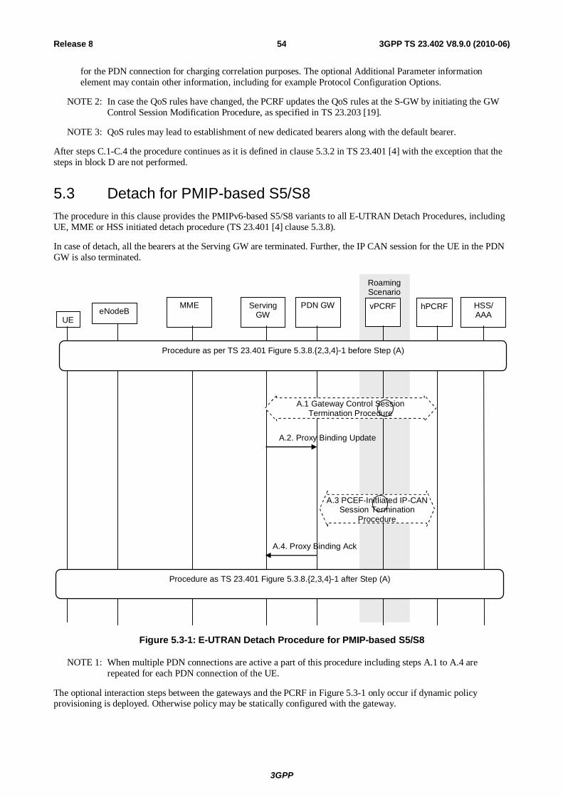
3GPP
3GPP TS 23.402 V8.9.0 (2010-06) 54Release 8
for the PDN connection for charging correlation purposes. The optional Additional Parameter information element may contain other information, including for example Protocol Configuration Options.
NOTE 2: In case the QoS rules have changed, the PCRF updates the QoS rules at the S-GW by initiating the GW Control Session Modification Procedure, as specified in TS 23.203 [19].
NOTE 3: QoS rules may lead to establishment of new dedicated bearers along with the default bearer.
After steps C.1-C.4 the procedure continues as it is defined in clause 5.3.2 in TS 23.401 [4] with the exception that the steps in block D are not performed.
5.3 Detach for PMIP-based S5/S8 The procedure in this clause provides the PMIPv6-based S5/S8 variants to all E-UTRAN Detach Procedures, including UE, MME or HSS initiated detach procedure (TS 23.401 [4] clause 5.3.8).
In case of detach, all the bearers at the Serving GW are terminated. Further, the IP CAN session for the UE in the PDN GW is also terminated.
PDN GW HSS/ AAA UE
eNodeB MME Serving
GW vPCRF
A.2. Proxy Binding Update
A.4. Proxy Binding Ack
hPCRF
Roaming Scenario
Procedure as per TS 23.401 Figure 5.3.8.{2,3,4}-1 before Step (A)
Procedure as TS 23.401 Figure 5.3.8.{2,3,4}-1 after Step (A)
A.1 Gateway Control Session Termination Procedure
A.3 PCEF-InitIiated IP-CAN Session Termination
Procedure
Figure 5.3-1: E-UTRAN Detach Procedure for PMIP-based S5/S8
NOTE 1: When multiple PDN connections are active a part of this procedure including steps A.1 to A.4 are repeated for each PDN connection of the UE.
The optional interaction steps between the gateways and the PCRF in Figure 5.3-1 only occur if dynamic policy provisioning is deployed. Otherwise policy may be statically configured with the gateway.

3GPP
3GPP TS 23.402 V8.9.0 (2010-06) 55Release 8
This procedure applies to the Non-Roaming (Figure 4.2.1-1), Roaming (Figure 4.2.1-2) and Local Breakout (Figure 4.2.3-4) cases. For the Roaming and Local Breakout cases, the vPCRF forwards messages between the Serving GW and the hPCRF. In the Local Breakout case, the vPCRF forwards messages between the PDN GW and the hPCRF.
in this case. In the non-roaming case, the vPCRF is not involved at all.
A.1) The Serving GW initiates the Gateway Control Session Termination Procedure with the PCRF as specified in TS 23.203 [19]. The S-GW provides information to enable the PCRF to unambiguously identify the IP-CAN session corresponding to the Gateway Control Session. This results in the removal of the Gateway Control session in S-GW.
A.2) The Serving GW sends a Proxy Binding Update (MN NAI, APN, lifetime=0) message to the PDN GW to release the PDN connection of the UE at the PDN-GW. The MN NAI and APN identify the PDN connection of the UE. The lifetime field indicates that the message is used to release the PDN connection of the UE at the PDN-GW.
A.3) The PDN GW initiates the PCEF-Initiated IP-CAN Session Termination Procedure with the PCRF as specified in TS 23.203 [19]. The PDN GW provides information to enable the PCRF to uniquely identify the IP-CAN session. This results in the removal of IP-CAN session related information in the PCRF and in the PDN GW.
A.4) The PDN GW responds to the Serving GW with the result of the PDN connection release with Proxy Binding Update Acknowledgement
5.4 Dedicated Bearer Procedures for E-UTRAN Access with PMIP-based S5/S8
5.4.1 General The procedure given in Figure 5.4.1-1 applies to all dedicated resource allocation operations for E-UTRAN which are triggered by PCRF, with the only exception of MME-initiated Dedicated Bearer Deactivation procedure which is covered in clause 5.4.5.3 The procedures initiated by the S-GW in the E-UTRAN differ for each case.
The procedure described in Figure 5.4.1-1 shows only the steps, due to PMIP based S5/S8, that are different from the GTP variant of the procedure given in TS 23.401 [4].
S-GW vPCRF UE eNB MME PDN GW
Dedicated bearer procedure as per TS 23.401, Figure 5.4.{1,3}-1 and 5.4.2.1-1 and 5.4.4.1-1,
between (A) and (B)
hPCRF
Roaming Scenario
B.2 PCC Rules Provision Procedure
A.1. Gateway Control and QoS Policy Rules Provision Procedure - begin
B.1. Gateway Control and QoS Policy Rules Provision Procedure - end
Figure 5.4.1-1: Dedicated Resource Allocation Procedure, UE in Active Mode
This procedure applies to the Non-Roaming (Figure 4.2.1-1), Roaming (Figure 4.2.1-2) and Local Breakout (Figure 4.2.3-4) cases. For the Roaming and Local Breakout cases, the vPCRF forwards messages between the Serving GW and the hPCRF. In the Local Breakout case, the vPCRF forwards messages between the PDN GW and the hPCRF.

3GPP
3GPP TS 23.402 V8.9.0 (2010-06) 56Release 8
If dynamic policy provision is not deployed, the steps shown in the figure are not taken. Instead, a configured static policy may be applied.
A.1) The PCRF initiates the Gateway Control and QoS Rules Provision Procedure specified in TS 23.203 [19] by sending a message with the QoS rules and Event Trigger information to the S-GW.
Steps between A.1 and B.1 are described in TS 23.401 [4], clauses 5.4.{1, 2.1, 3, 4.1}.
NOTE: For a PMIP-based S5/S8, before procedure steps (step 3 of TS 23.401 [4], clause 5.4.1), the PCRF sends a PCC decision provision (QoS policy) message to the S-GW and not to the P-GW as done for GTP-based S5/S8. The S-GW uses this QoS policy to determine that traffic flow(s) shall be aggregated to or removed from an active bearer. The S-GW generates the TFT and updates the EPS Bearer QoS to match the aggregated set of traffic flows. It is possible that the S-GW bearer binding function will result in the modification, creation or removal of bearers at this point. For modification, the S-GW sends an Update Bearer Request (PTI, EPS Bearer Identity, EPS Bearer QoS, TFT) message to the MME. For creation of a dedicated bearer, the S-GW sends a Create Bearer message and for removal, the S-GW sends a Delete Bearer Request.
B.1) The Serving GW indicates to the PCRF whether the requested QoS Policy Rules Provision could be enforced or not thus completing the GW Control and QoS Rules Provision procedure started in step A.1.
B.2) The PCRF initiates the PCC Rules Provision Procedure as specified in TS 23.203 [19]. The PCRF provides updated PCC rules to the PCEF for enforcement by means of an PCC Rules Provision procedure specified in TS 23.203 [19].
NOTE: Step B.2 may occur before step A.1 or performed in parallel with steps A.1-B.1 if acknowledgement of resource allocation is not required to update PCC rules in PCEF. For details please refer to TS 23.203 [19].
5.4.2 Dedicated Bearer Activation When the QoS Policy rules provided by the PCRF to the Serving Gateway in Step A.1 of figure 5.4.1-1 above results in the Serving Gateway to decide to activate a dedicated bearer, this procedure is applied.
The procedure depicted in Figure 5.4.1-1 applies for this case. On receiving message A.1, the Serving GW decides that a new bearer needs to be activated, the Serving GW uses this QoS policy to assign the EPS Bearer QoS, i.e., it assigns the values to the bearer level QoS parameters (excluding AMBR); see TS 23.401 [4] clause 4.7.3. The Serving GW follows the procedure shown in TS 23.401 [4], clause 5.4.1 by sending a Create Bearer Request message (EPS Bearer QoS, TFT, S1 TEID) to the MME.
The message descriptions for A.1, B.1 and B.2 in clause 5.4.1 apply to this case as well. The steps between A.1 and B.1 are described in TS 23.401 [4], clause 5.4.1.
5.4.3 Bearer Modification with Bearer QoS Update
5.4.3.1 PCC Initiated Bearer Modification with Bearer QoS Update
When the QoS Policy rules provided by the PCRF to the Serving Gateway in step A.1 of Figure 5.4.1-1 above results in the Serving Gateway to decide to modify the QoS of an already existing bearer, this procedure is applied. QoS modification may result in a bearer modification in the E-UTRAN access.
The procedure depicted in Figure 5.4.1-1 applies to this case as well. On receiving message A.1, the Serving GW uses this QoS policy to determine that traffic flow(s) shall be aggregated to or removed from an active bearer. The Serving GW generates the TFT and updates the EPS Bearer QoS to match the aggregated set of traffic flows. The Serving GW then follows the procedure shown in TS 23.401 [4], clause 5.4.2 by sending the Update Bearer Request (EPS Bearer QoS, TFT) message to the MME.
The message descriptions for A.1, B.1 and B.2 in clause 5.4.1 apply to this procedure as well. The steps between A.1 and B.1 are described in TS 23.401 [4], clause 5.4.2.1.

3GPP
3GPP TS 23.402 V8.9.0 (2010-06) 57Release 8
5.4.3.2 HSS-Initiated Subscribed QoS Modification
The HSS Initiated Subscribed QoS Modification for a PMIP-based S5/S8 is depicted in Figure 5.4.3.2-1.
S-GW vPCRF UE eNB MME PDN GW
Bearer procedure as per TS 23.401, Figure 5.4.2.2-1, between steps (A) and (B)
hPCRF
Roaming Scenario
HSS
Procedure as per TS 23.401, Figure 5.4.2.2-1, before Step (A)
A.1 GW Control and QoS Policy Rules Request Procedure - begin
A.2 PCC Rules Provision Procedure
B.1 Gateway Control and QoS Policy Rules Request Procedure - end
B.2 PCC Rules Provision
Procedure
Figure 5.4.3.2-1: HSS-initiated Subscribed QoS Modification
A.1. The Serving GW initiates the Gateway Control and QoS Policy Rules Request Procedure with the PCRF as specified in TS 23.203 [19]. The S-GW provides the updated default EPS Bearer QoS for the default bearer to the PCRF and the PCRF responds with updated QoS rules. The PCRF makes a PCC decision as a result of the Gateway Control and QoS policy request and provides the updated QoS Rules to the Serving GW.
A.2. The PCRF initiates the PCC Rules Provision Procedure with the PDN GW as specified in TS 23.203 [19] to updates the rules in the PDN GW.
After Step A.1, the Serving GW follows the procedure shown in TS 23.401 [4], clause 5.4.2.1 by sending the Update Bearer Request message to the MME. The procedure is completed when the Serving GW receives a Update Bearer Response from the MME in Step 10 of TS 23.401 [4] clause 5.4.2.1.
B.1. The Serving GW indicates to the PCRF whether the requested QoS Policy Rules Provision could be enforced or not and thus completing the GW Control and QoS Rules Provision procedure started in step A.1.
B.2. The PCRF executes the Policy and Charging Rules Provision Procedure as specified in TS 23.203 [19] to update the PCC rules in the PDN GW.
NOTE: Step B.2 may be performed in parallel with steps A.1-B.1 if acknowledgement of resource allocation is not required at the PCRF to update PCC rules in PCEF. For details please refer to TS 23.203 [19].
5.4.4 Dedicated Bearer Modification without Bearer QoS Update When the QoS Policy rules provided by the PCRF to the Serving Gateway in step A.1 of figure 5.4.1-1 above results in the Serving Gateway to decide to only update the set of TFTs corresponding to an already existing dedicated bearer, this procedure is applied.
NOTE: If neither the contents of the TFT nor the APN-AMBR are modified, this procedure does not apply.
The procedure depicted in Figure 5.4.1-1 applies to this case as well. On receiving message A.1, the Serving GW uses this QoS policy to determine that traffic flow(s) shall be aggregated to or removed from an active dedicated bearer. The Serving GW generates the TFT and determines that no update of the EPS Bearer QoS is needed. The Serving GW then
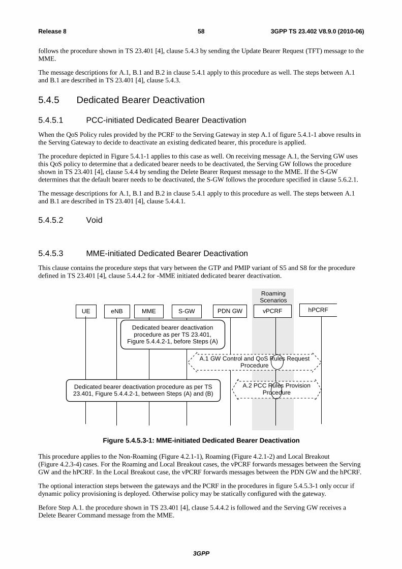
3GPP
3GPP TS 23.402 V8.9.0 (2010-06) 58Release 8
follows the procedure shown in TS 23.401 [4], clause 5.4.3 by sending the Update Bearer Request (TFT) message to the MME.
The message descriptions for A.1, B.1 and B.2 in clause 5.4.1 apply to this procedure as well. The steps between A.1 and B.1 are described in TS 23.401 [4], clause 5.4.3.
5.4.5 Dedicated Bearer Deactivation
5.4.5.1 PCC-initiated Dedicated Bearer Deactivation
When the QoS Policy rules provided by the PCRF to the Serving Gateway in step A.1 of figure 5.4.1-1 above results in the Serving Gateway to decide to deactivate an existing dedicated bearer, this procedure is applied.
The procedure depicted in Figure 5.4.1-1 applies to this case as well. On receiving message A.1, the Serving GW uses this QoS policy to determine that a dedicated bearer needs to be deactivated, the Serving GW follows the procedure shown in TS 23.401 [4], clause 5.4.4 by sending the Delete Bearer Request message to the MME. If the S-GW determines that the default bearer needs to be deactivated, the S-GW follows the procedure specified in clause 5.6.2.1.
The message descriptions for A.1, B.1 and B.2 in clause 5.4.1 apply to this procedure as well. The steps between A.1 and B.1 are described in TS 23.401 [4], clause 5.4.4.1.
5.4.5.2 Void
5.4.5.3 MME-initiated Dedicated Bearer Deactivation
This clause contains the procedure steps that vary between the GTP and PMIP variant of S5 and S8 for the procedure defined in TS 23.401 [4], clause 5.4.4.2 for -MME initiated dedicated bearer deactivation.
S-GW vPCRF UE eNB MME PDN GW hPCRF
Dedicated bearer deactivation procedure as per TS 23.401, Figure 5.4.4.2-1, between Steps (A) and (B)
Dedicated bearer deactivation procedure as per TS 23.401,
Figure 5.4.4.2-1, before Steps (A)
Roaming Scenarios
A.2 PCC Rules Provision Procedure
A.1 GW Control and QoS Rules Request Procedure
Figure 5.4.5.3-1: MME-initiated Dedicated Bearer Deactivation
This procedure applies to the Non-Roaming (Figure 4.2.1-1), Roaming (Figure 4.2.1-2) and Local Breakout (Figure 4.2.3-4) cases. For the Roaming and Local Breakout cases, the vPCRF forwards messages between the Serving GW and the hPCRF. In the Local Breakout case, the vPCRF forwards messages between the PDN GW and the hPCRF.
The optional interaction steps between the gateways and the PCRF in the procedures in figure 5.4.5.3-1 only occur if dynamic policy provisioning is deployed. Otherwise policy may be statically configured with the gateway.
Before Step A.1. the procedure shown in TS 23.401 [4], clause 5.4.4.2 is followed and the Serving GW receives a Delete Bearer Command message from the MME.

3GPP
3GPP TS 23.402 V8.9.0 (2010-06) 59Release 8
A.1) The Serving GW decides to deactivate the bearers and initiates the Gateway Control and QoS Policy Rules Request Procedure with the PCRF as specified in TS 23.203 [19]. The Serving GW informs the PCRF about the deleted QoS Rules.
A.2) The PCRF initiates the PCC Rules Provision Procedure with the PDN GW as specified in TS 23.203 [19] to updates the rules in the PDN GW. The PCC rules provide the PDN GW with information required to enforce the remaining dedicated resource allocation policy, after removing PCC rules corresponding to the QoS rules deactivated by step A.1.
After step A.1, the Serving GW follows the procedure shown in TS 23.401 [4], clause 5.4.4.2 by sending the Delete Bearer Request message to the MME. The Serving GW does not need to wait for step A.1 to complete to proceed with the deactivation of bearers with the MME. The procedure is completed when the Serving GW receives a Delete Bearer Response from the MME in Step 8 of TS 23.401 [4], clause 5.4.4.2.
5.5 UE-initiated Resource Request and Release This clause is related to the case when UE-initiated resource request and release is supported, and it is utilized for the PMIP-based S5/S8 traffic flow aggregates.
In the non-roaming case, vPCRF will not be involved.
UE PDN GW vPCRF hPCRF Serving GW
UE requested bearer resource modification procedure as per TS 23.401,
Figure 5.4.5-1 before Step A
Roaming Scenarios
Dedicated bearer activation/modification procedure as per TS 23.401, Figure 5.4.{1,2.1, 2.2, 3}-1 between Step A and B; or Dedicated bearer deactivation procedure as per figure 5.4.4.1-1 from Steps 3a to Step 8a.
A.1 Gateway Control and QoS Rules Request -begin
B.2 PCC Rules Provision Procedure
B.1 Gateway Control and QoS Policy Rules Request - end
Figure 5.5-1: UE-initiated resource request/release with PMIP-based S5/S8
This procedure applies to the Non-Roaming (Figure 4.2.1-1), Roaming (Figure 4.2.1-2) and Local Breakout (Figure 4.2.3-4) cases. For the Roaming and Local Breakout cases, the vPCRF forwards messages between the Serving GW and the hPCRF. In the Local Breakout case, the vPCRF forwards messages between the PDN GW and the hPCRF.
The optional interaction steps between the gateways and the PCRF in the procedures in Figure 5.5-1 only occur if dynamic policy provisioning is deployed. Otherwise policy may be statically configured with the gateway.
A.1. The Serving GW initiates the Gateway Control and QoS Policy Rules Request Procedure as specified in TS 23.203 [19]. The Serving GW provides the content of the Traffic Aggregate Description (TAD) and the

3GPP
3GPP TS 23.402 V8.9.0 (2010-06) 60Release 8
requested QoS change to the PCRF as an Event Report. The PCRF makes a PCC decision as a result of the Gateway Control and QoS policy request and provides the updated QoS Rules to the Serving GW.
Steps between A.1 and B.1 are described in TS 23.401 [4], clauses 5.4.1, 5.4.2 and 5.4.3 for resource allocation/modification or clause 5.4.4.1 for resource deactivation. Based on the QoS policy rules, the Serving GW decides whether to initiate a dedicated resource allocation activation or dedicated resource allocation modification (with or without QoS update).The Serving GW uses this QoS policy to assign the EPS Bearer QoS, i.e. it assigns the values to the bearer level QoS parameters (excluding AMBR); see clause 4.7.3 of TS 23.401 [4] and sends the appropriate message to the MME.
B.1. The Serving GW indicates to the PCRF whether the requested QoS Policy Rules Provision could be enforced or not and thus completing the GW Control and QoS Rules Provision procedure started in step A.1.
B.2. The PCRF initiates the Policy and Charging Rules Provision Procedure as specified in TS 23.203 [19] to update the PCC rules in the PDN GW.
NOTE: Step B.2 may be performed in parallel with Steps A.1-B1 if acknowledgement of resource allocation is not required at the PCRF to update PCC rules in PCEF. For details please refer to TS 23.203 [19].
5.6 Multiple PDN Support with PMIP-based S5/S8
5.6.1 UE requested PDN connectivity The UE requested PDN connectivity procedure for an E-UTRAN is depicted in figure 5.6.1-1. The procedure allows the UE to request for connectivity to a PDN including allocation of a default bearer. In this procedure, the UE is assumed to be in active mode. Proxy Mobile IP is used on S5 or S8 interface. It is assumed that the MAG is collocated with the Serving GW for the PMIPv6 procedure between the Serving GW and the PDN GW.
When only GTP-based S5 or S8 connections are established for roamers from a PMIP network into a GTP network the procedure as described in clause 5.10.2 of TS 23.401 [4] applies.
When PMIP-based S5/S8 is used, at most one PDN connection per APN is supported. If the UE requests a PDN connection for an APN for which the UE already has an active PDN connection, the MME shall reject the PDN connectivity request.
The procedure is also used for the re-establishment of existing PDN connectivity after the UE performed the handover from non-3GPP accesses for the first PDN connection by the Attach procedure. The UE triggers the re-establishment of existing PDN connectivity after the handover by providing a Request Type indicating "Handover" as specified in TS 23.401 [4].

3GPP
3GPP TS 23.402 V8.9.0 (2010-06) 61Release 8
A.4 Proxy Binding Ack
A.2 Proxy Binding Update
new MME old MME Serving GW hPCRF HSS/AAA PDN GW eNodeB UE
UE Requested PDN connectivity procedure as in TS 23.401, Figure 5.10.2-1, before step (A)
UE Requested PDN connectivity procedure as in TS 23.401, Figure 5.10.2-1, between step (A) and step (B)
vPCRF
A.1 Gateway Control Session Establishment Procedure
A.3a IP-CAN Session Establishment Procedure
Roaming Scenarios
UE Requested PDN connectivity procedure as in TS 23.401, Figure 5.10.2-1, after step (B)
Alt. A)
B.1 Proxy Binding Update
B.2 PCEF-Initiated IP-CAN Session
Modification Procedure
B.3 Proxy Binding Ack
Alt. B)
A.3b PCEF-Initiated IP-CAN Session
Modification Procedure
(C)
(D)
Figure 5.6.1-1: UE requested PDN connectivity with PMIP-based S5 or S8
This procedure applies to the Non-Roaming (Figure 4.2.1-1), Roaming (Figure 4.2.1-2) and Local Breakout (Figure 4.2.3-4) cases. For the Roaming and Local Breakout cases, the vPCRF forwards messages between the Serving GW and the hPCRF. In the Local Breakout case, the vPCRF forwards messages between the PDN GW and the hPCRF.
The optional interaction steps between the gateways and the PCRF in the procedures in figure 5.6.1-1 only occur if dynamic policy provisioning is deployed. Otherwise policy may be statically configured with the gateway.
For UE request additional PDN connectivity to PDNs when connected to 3GPP access network with PMIP-based S5 or S8, the IP address is not available after step A1, steps in (Alt A) are performed after step A.1, excluding steps in (Alt B). The step in (C) is performed only when the UE establishes additional PDN connectivity with a PDN it is not already connected to, excluding step (D).
3GPP
3GPP TS 23.402 V8.9.0 (2010-06) 62Release 8
For re-establishment of existing PDN connectivity after the UE performed the handover from non-3GPP accesses, the steps shown in (Alt A) and (Alt B) are mutually exclusive in this procedure, i.e. either steps A.2-A.4 are executed or steps B.1-B.3. In order to execute the alternative (Alt B), the IP address of the UE needs to be available after step A.1. The IP Address(es) of the UE is received in step A.1, if dynamic policy provisioning is deployed.
In case the IP address(es) of the UE is available after step A.1, (Alt B) provides lower jitter for dual radio handovers. In case the IP address(es) of the UE is not available after step A.1, (Alt A) shall be used.
For re-establishment of existing PDN connectivity after the UE performed the handover from non-3GPP accesses, the following also applies:
- In step A.2/B.1 the Serving GW sets the Handover Indicator to "handover".
- The step in (D) and step B.2 are performed only when the UE re-establishes PDN connectivity after a handover. The steps in (D) correspond to the PCEF-Initiated IP-CAN Session Modification procedure specified in TS 23.203 [19].
- In step A.4/B.3, the UE Address Info shall contain the IP address the UE obtained during PDN connectivity establishment for this PDN over the non-3GPP access. The PDN GW also includes the Charging Id for the PDN connection in the Proxy binding acknowledgements.
The steps A.1-A.4 correspond to steps C.1-C.4 in clause 5.2-1.
The steps B.1-B.3 correspond to steps A.2, A.3b, A.4.
5.6.2 PDN Disconnection
5.6.2.1 UE, MME or S-GW initiated PDN Disconnection
When GTP-based S5 or S8 is used the procedure described in clause 5.10.3 of TS 23.401 [4] applies for the UE or MME initiated PDN disconnection. The PMIP variant of this procedure is specified below. In addition, if the default bearer belonging to a PDN connection is to be deactivated by the S-GW, e.g. due to un-successful modification of QoS of default bearer that was triggered by PCRF interaction, the S-GW deactivates all bearers belonging to the PDN connection using the following procedure.

3GPP
3GPP TS 23.402 V8.9.0 (2010-06) 63Release 8
PDN GW HSS/ AAA UE
eNodeB MME Serving
GW vPCRF
A.2. Proxy Binding Update
A.4. Proxy Binding Ack
hPCRF
Roaming Scenario
Procedure as per TS 23.401 Figure 5.10.3-1 before Step (A) for UE/MME initiated PDN disconnection
Procedure as TS 23.401 Figure 5.10.3-1 after Step (A) for UE/MME initiated PDN disconnection, or Figure 5.4.4.1-1 after Step (A) for S-GW initiated PDN disconnection
A.1 Gateway Control Session Termination Procedure
A.3 PCEF-InitIiated IP-CAN Session Termination
Procedure
Figure 5.6.2-1: UE, MME or S-GW initiated PDN disconnection Procedure for PMIP-based S5/S8
Steps A.1 to A.4 are described in clause 5.3. For the case of S-GW initiated PDN disconnection, which corresponds to PDN GW initiated bearer deactivation procedure of clause 5.4.4.1 of TS 23.401 [4], the procedure starts from step A.1 and there are no steps corresponding to box (B) of figure 5.4.4.1-1 of TS 23.401 [4].
5.6.2.2 PDN-GW-initiated PDN Disconnection
The default bearer and all the dedicated resource allocations associated with the PDN address are released in this procedure.

3GPP
3GPP TS 23.402 V8.9.0 (2010-06) 64Release 8
UE
A. 1. Binding Revocation Request
B.2. Binding Revocation Ack
PDN GW
eNodeB MME Serving GW
vPCRF hPCRF
Procedure as per Figure 5.4.4.1-1 between Step (A) and Step (B) in TS 23.401
B.1 BBERF-Initiated GW Control Session Termination Procedure
Figure 5.6.2.2-1: PDN GW initiated PDN Disconnection Procedure for PMIP-based S5/S8
This procedure applies to the Non-Roaming (Figure 4.2.1-1), Roaming (Figure 4.2.1-2) and Local Breakout (Figure 4.2.3-4) cases. For the Roaming and Local Breakout cases, the vPCRF forwards messages between the Serving GW and the hPCRF. In the Local Breakout case, the vPCRF forwards messages between the PDN GW and the hPCRF.
The optional interaction steps between the gateways and the PCRF in the procedures in figure 5.6.2.2-1 only occur if dynamic policy provisioning is deployed. Otherwise policy may be statically configured with the gateway.
A.1. The PDN GW sends a Binding Revocation Indication (PDN address) message to the Serving GW as defined in draft-ietf-mext-binding-revocation [35].
Steps between A and B are described in clause 5.4.4.1 of TS 23.401 [4], using the indication that all bearers belonging to the given PDN address shall be released.
B.1. The Serving GW initiates the Gateway Control Session Termination Procedure with the PCRF as specified in TS 23.203 [19]. The S-GW provides the information to enable the PCRF to uniquely identify the IP-CAN session. This results in the removal of the Gateway Control session in S-GW.
B.2. The Serving GW returns a Binding Revocation Acknowledgement message to the PDN GW.
NOTE: Step B.2 may occur before steps B.1 since the Serving GW need not wait for terminating the GW Control Session with the PCRF before acknowledging the Binding Revocation.
5.7 Handover and Tracking area Update Procedures for PMIP-based S5/S8 Interface
5.7.1 Intra-LTE TAU and Inter-eNodeB Handover with Serving GW Relocation
This clause contains the procedure steps that vary between the GTP and PMIP variant of S5 and S8 for the TAU with MME and Serving GW change procedure defined in TS 23.401 [4], clause 5.3.3.1 as well as Inter-eNodeB Handover with CN Node Relocation described in TS 23.401 [4], clause 5.5.1.2.
In case of a Serving GW relocation, the target Serving GW must establish a Gateway Control Session with the PCRF to perform policy controlled functions such as Bearer-Binding. The source Serving GW relinquishes its Gateway Control Session with the PCRF in step B.
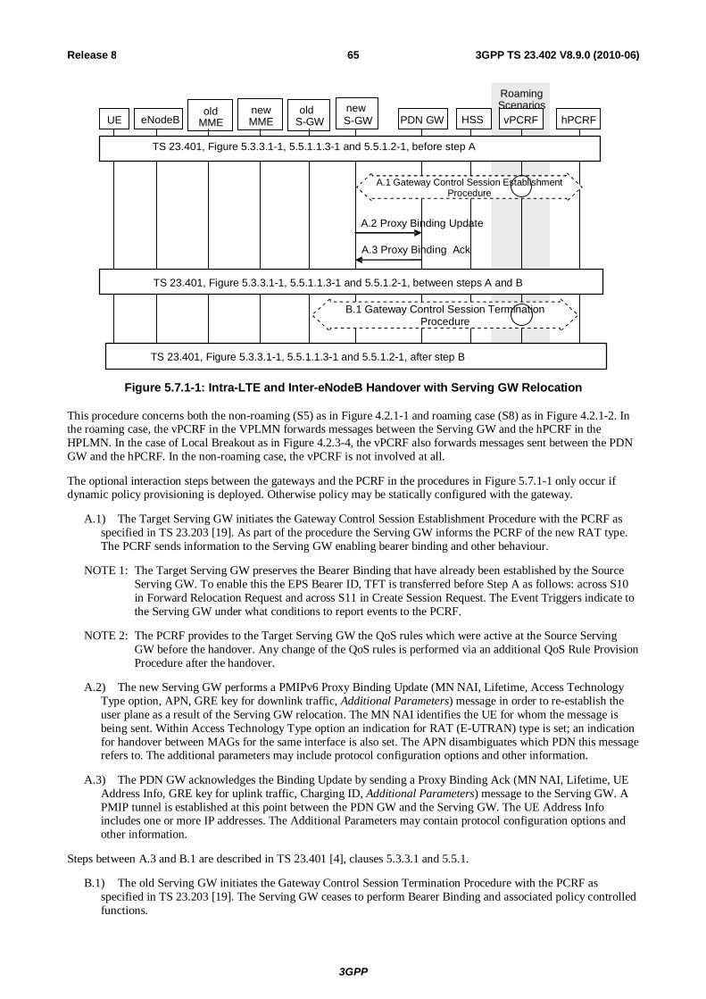
3GPP
3GPP TS 23.402 V8.9.0 (2010-06) 65Release 8
Roaming Scenarios
UE eNodeB new MME PDN GW
old MME
old S-GW
new S-GW
HSS vPCRF
hPCRF
TS 23.401, Figure 5.3.3.1-1, 5.5.1.1.3-1 and 5.5.1.2-1, before step A
A.2 Proxy Binding Update
A.3 Proxy Binding Ack
A.1 Gateway Control Session Establishment Procedure
B.1 Gateway Control Session Termination Procedure
TS 23.401, Figure 5.3.3.1-1, 5.5.1.1.3-1 and 5.5.1.2-1, between steps A and B
TS 23.401, Figure 5.3.3.1-1, 5.5.1.1.3-1 and 5.5.1.2-1, after step B
Figure 5.7.1-1: Intra-LTE and Inter-eNodeB Handover with Serving GW Relocation
This procedure concerns both the non-roaming (S5) as in Figure 4.2.1-1 and roaming case (S8) as in Figure 4.2.1-2. In the roaming case, the vPCRF in the VPLMN forwards messages between the Serving GW and the hPCRF in the HPLMN. In the case of Local Breakout as in Figure 4.2.3-4, the vPCRF also forwards messages sent between the PDN GW and the hPCRF. In the non-roaming case, the vPCRF is not involved at all.
The optional interaction steps between the gateways and the PCRF in the procedures in Figure 5.7.1-1 only occur if dynamic policy provisioning is deployed. Otherwise policy may be statically configured with the gateway.
A.1) The Target Serving GW initiates the Gateway Control Session Establishment Procedure with the PCRF as specified in TS 23.203 [19]. As part of the procedure the Serving GW informs the PCRF of the new RAT type. The PCRF sends information to the Serving GW enabling bearer binding and other behaviour.
NOTE 1: The Target Serving GW preserves the Bearer Binding that have already been established by the Source Serving GW. To enable this the EPS Bearer ID, TFT is transferred before Step A as follows: across S10 in Forward Relocation Request and across S11 in Create Session Request. The Event Triggers indicate to the Serving GW under what conditions to report events to the PCRF.
NOTE 2: The PCRF provides to the Target Serving GW the QoS rules which were active at the Source Serving GW before the handover. Any change of the QoS rules is performed via an additional QoS Rule Provision Procedure after the handover.
A.2) The new Serving GW performs a PMIPv6 Proxy Binding Update (MN NAI, Lifetime, Access Technology Type option, APN, GRE key for downlink traffic, Additional Parameters) message in order to re-establish the user plane as a result of the Serving GW relocation. The MN NAI identifies the UE for whom the message is being sent. Within Access Technology Type option an indication for RAT (E-UTRAN) type is set; an indication for handover between MAGs for the same interface is also set. The APN disambiguates which PDN this message refers to. The additional parameters may include protocol configuration options and other information.
A.3) The PDN GW acknowledges the Binding Update by sending a Proxy Binding Ack (MN NAI, Lifetime, UE Address Info, GRE key for uplink traffic, Charging ID, Additional Parameters) message to the Serving GW. A PMIP tunnel is established at this point between the PDN GW and the Serving GW. The UE Address Info includes one or more IP addresses. The Additional Parameters may contain protocol configuration options and other information.
Steps between A.3 and B.1 are described in TS 23.401 [4], clauses 5.3.3.1 and 5.5.1.
B.1) The old Serving GW initiates the Gateway Control Session Termination Procedure with the PCRF as specified in TS 23.203 [19]. The Serving GW ceases to perform Bearer Binding and associated policy controlled functions.
3GPP
3GPP TS 23.402 V8.9.0 (2010-06) 66Release 8
5.7.2 TAU/RAU or Handover between GERAN A/Gb Mode or UTRAN Iu Mode and E-UTRAN
In case of inter-RAT TAU/RAU or handovers, the Serving GW may or may not be relocated. The PMIP based S5/S8 variants procedure steps for inter-RAT TAU/RAU or handover without Serving GW relocation is shown in Figure 5.7.2-1 and those corresponding to a change of Serving GW is shown in Figure 5.7.2-2.
The procedures in this clause correspond to the following Figures in TS 23.401 [4]:
- Figure 5.3.3.2-1 [UTRAN Iu mode to E-UTRAN] Tracking Area Update.
- Figure 5.3.3.3-1E-UTRAN to UTRAN/GERAN RA Update.
- Figure 5.3.3.6-1 E-UTRAN to GERAN A/Gb mode Routeing Area Update.
- Figure 5.5.2.1.3-1: E-UTRAN to UTRAN Iu mode Inter RAT HO, execution phase.
- Figure 5.5.2.2.3-1: UTRAN Iu mode to E-UTRAN Inter RAT HO, execution phase.
- Figure 5.5.2.3.3-1: E-UTRAN to GERAN A/Gb mode Inter RAT HO, execution phase.
- Figure 5.5.2.4.3-1: GERAN A/Gb mode to E-UTRAN Inter RAT HO, execution phase.
The procedure also applies to Figure 5.5.1.1.2-1 "X2-based handover without Serving GW relocation". The User Location Information IE may be received by the Serving GW from the MME. In this case the Serving GW forwards this information to the PDN GW by means of this procedure.
In TS 23.401 [4], the clauses corresponding to Figure 5.7.2-1 and Figure 5.7.2-2 cover both the case of Serving GW relocation and no Serving GW relocation. In case of no Serving GW relocation, Steps (A) in the above figures are between the un-changed Serving GW and the PCRF and the Steps (B) in those figures do not apply, as shown in Figure 5.7.2-1. In case of Serving GW relocation, Steps (A) in the above figure are between the target Serving GW and the PCRF and the Steps (B) is between the source Serving GW and the PCRF, as shown in Figure 5.7.2-2.
In case of no Serving GW relocation, the S-GW signals the change of RAT to the PCRF. In addition, if the Serving GW has received the User Location Information IE from the MME, this information is also sent to the PCRF. If PCC rules provided to the PDN-GW have changed, the PCRF updates these rules at the PDN-GW. The PCRF sends the RAT Type change or User Location Information to the PDN GW.
The user plane already exists between the Serving GW and the PDN GW and remains unchanged. In case of RAU or handover to 2G/3G, user plane routing is assumed to proceed over the S4 interface towards the S2/S3 SGSN. When an inter-RAT TAU occurs, the enhanced packet core may signal this event to the PDN GW, for example to inform the PDN GW of a RAT type change. In the case of a PMIP-based S5 and S8, a Modify Bearer Request is not sent from the Serving GW to the PDN GW. Instead, the PCRF in the HPLMN reports the change of event. The PCRF signals any change in the policy resulting from the event to the PDN GW, provisioning updated policy and charging rules.
In case dynamic PCC is not deployed, a change of RAT type will not be signalled to the PDN GW using PMIP based S5/S8 interfaces, if no change of Serving GW has occurred.

3GPP
3GPP TS 23.402 V8.9.0 (2010-06) 67Release 8
Roaming Scenarios
Serving GW
PDN GW
HSS vPCRF hPCRF
TS 23.401, Figures 5.3.3.{2,3}-1 and 5.5.2.{1,2,3,4}.3-1, before step A.
A.1 Gateway Control and QoS Rules Request Procedure
A.2 PCC Rules Provision Procedure
TS 23.401, Figures 5.3.3.{2,3}-1 and 5.5.2.{1,2,3,4}.3-1, before step A.
Figure 5.7.2-1: Inter-RAT TAU/RAU or Handover without Serving GW relocation
This procedure applies to the Non-Roaming (Figure 4.2.1-1), Roaming (Figure 4.2.1-2) and Local Breakout (Figure 4.2.3-4) cases. For the Roaming and Local Breakout cases, the vPCRF forwards messages between the Serving GW and the hPCRF. In the Local Breakout case, the vPCRF forwards messages between the PDN GW and the hPCRF.
The optional interaction steps between the gateways and the PCRF in the procedures in Figure 5.7.2-1 only occur if dynamic policy provisioning is deployed. Otherwise policy may be statically configured with the gateway.
A.1) The Serving GW informs the PCRF about the change of RAT type and UE Location Information IE (if this has been received from the MME preceding step A) by initiating the Gateway Control and QoS Policy Rules Request Procedure as specified in TS 23.203 [19].
A.2) The PCRF updates the PCC rules at the PDN GW by initiating the PCC Rules Provision Procedure as specified in TS 23.203 [19] if the PCC rules have changed based on the RAT type reported by the Serving GW in step A.1. Further, the hPCRF notifies the PDN GW of the change in RAT and the UE Location Information IE (if this has been received from the MME preceding step A).
Step A.2 may be initiated before A.1 completes.
The following procedure describes inter-RAT TAU/RAU or Handover in the case of Serving Gateway relocation for PMIP-based S5/S8.
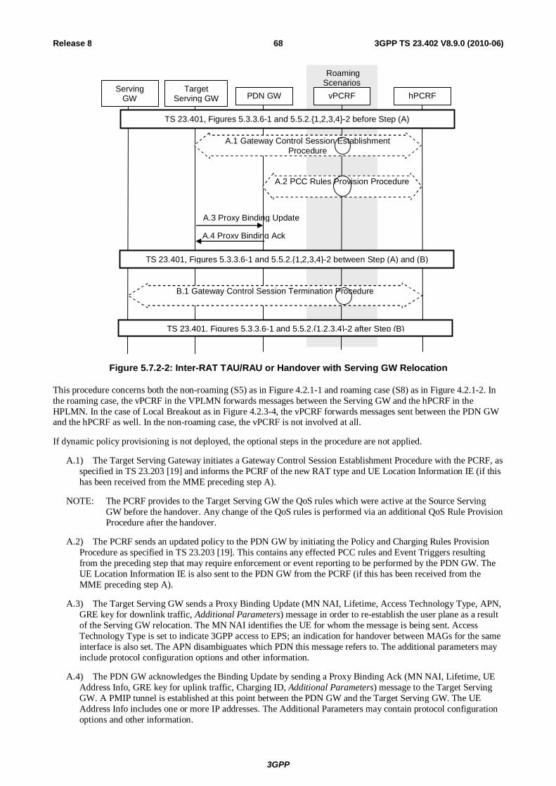
3GPP
3GPP TS 23.402 V8.9.0 (2010-06) 68Release 8
Roaming Scenarios
Target Serving GW PDN GW vPCRF hPCRF
Serving GW
A.3 Proxy Binding Update
A.4 Proxy Binding Ack
TS 23.401, Figures 5.3.3.6-1 and 5.5.2.{1,2,3,4}-2 after Step (B)
TS 23.401, Figures 5.3.3.6-1 and 5.5.2.{1,2,3,4}-2 before Step (A)
TS 23.401, Figures 5.3.3.6-1 and 5.5.2.{1,2,3,4}-2 between Step (A) and (B)
A.1 Gateway Control Session Establishment Procedure
A.2 PCC Rules Provision Procedure
B.1 Gateway Control Session Termination Procedure
Figure 5.7.2-2: Inter-RAT TAU/RAU or Handover with Serving GW Relocation
This procedure concerns both the non-roaming (S5) as in Figure 4.2.1-1 and roaming case (S8) as in Figure 4.2.1-2. In the roaming case, the vPCRF in the VPLMN forwards messages between the Serving GW and the hPCRF in the HPLMN. In the case of Local Breakout as in Figure 4.2.3-4, the vPCRF forwards messages sent between the PDN GW and the hPCRF as well. In the non-roaming case, the vPCRF is not involved at all.
If dynamic policy provisioning is not deployed, the optional steps in the procedure are not applied.
A.1) The Target Serving Gateway initiates a Gateway Control Session Establishment Procedure with the PCRF, as specified in TS 23.203 [19] and informs the PCRF of the new RAT type and UE Location Information IE (if this has been received from the MME preceding step A).
NOTE: The PCRF provides to the Target Serving GW the QoS rules which were active at the Source Serving GW before the handover. Any change of the QoS rules is performed via an additional QoS Rule Provision Procedure after the handover.
A.2) The PCRF sends an updated policy to the PDN GW by initiating the Policy and Charging Rules Provision Procedure as specified in TS 23.203 [19]. This contains any effected PCC rules and Event Triggers resulting from the preceding step that may require enforcement or event reporting to be performed by the PDN GW. The UE Location Information IE is also sent to the PDN GW from the PCRF (if this has been received from the MME preceding step A).
A.3) The Target Serving GW sends a Proxy Binding Update (MN NAI, Lifetime, Access Technology Type, APN, GRE key for downlink traffic, Additional Parameters) message in order to re-establish the user plane as a result of the Serving GW relocation. The MN NAI identifies the UE for whom the message is being sent. Access Technology Type is set to indicate 3GPP access to EPS; an indication for handover between MAGs for the same interface is also set. The APN disambiguates which PDN this message refers to. The additional parameters may include protocol configuration options and other information.
A.4) The PDN GW acknowledges the Binding Update by sending a Proxy Binding Ack (MN NAI, Lifetime, UE Address Info, GRE key for uplink traffic, Charging ID, Additional Parameters) message to the Target Serving GW. A PMIP tunnel is established at this point between the PDN GW and the Target Serving GW. The UE Address Info includes one or more IP addresses. The Additional Parameters may contain protocol configuration options and other information.

3GPP
3GPP TS 23.402 V8.9.0 (2010-06) 69Release 8
Steps between A.4 and B.1 are described in the clauses of TS 23.401 [4], containing the figures referenced in Figure 5.7.2-1 above.
B.1) The old Serving GW initiates the Gateway Control Session Termination Procedure with the PCRF, as specified in TS 23.203 [19]. The S-GW provides information to enable the PCRF to uniquely identify the IP-CAN session. This results in the removal of the Gateway Control session in S-GW.
5.8 ME Identity Check Procedures for PMIP-based S5/S8 ME identity check by the MME in case of PMIP-based S5/S8 is performed as defined for GTP-based S5/S8, see clause 5.3.2.1 (E-UTRAN Initial Attach procedure) of TS 23.401 [4].
No ME identity check support is specified on the S5/S8 reference point.
5.9 UE-triggered Service Request for PMIP-based S5/S8 This clause contains the procedure steps that vary between the GTP and PMIP variant of S5 and S8 for the UE-triggered Service Request procedure defined in TS 23.401 [4], clause 5.3.4.1, for the case where the RAT Type reported in the Service Request has changed compared to the last reported RAT Type.
Roaming Scenarios
UE vPCRF Serving
GW hPCRF PDN GW
A.2 PCC Rules Provision Procedure
A.1 Gateway Control and QoS Rules Request Procedure
UE triggered Service Request procedure as per TS 23.401, Figure 5.3.4.1-1 before step (A)
UE triggered Service Request procedure as per TS 23.401, Figure 5.3.4.1-1 after step (A)
Figure 5.9-1: UE-triggered Service Request for PMIP-based S5/S8
This procedure concerns both the non-roaming (S5) and roaming case (S8). In the roaming case, the vPCRF in the VPLMN forwards messages between the Serving GW and the hPCRF in the HPLMN. In the case of Local Breakout, the vPCRF forwards messages sent between the PDN GW and the hPCRF as well. In the non-roaming case, the vPCRF is not involved at all.
The optional interaction steps between the gateways and the PCRF in the procedures in Figure 5.9-1 only occur if dynamic policy provisioning is deployed. Otherwise policy may be statically configured with the gateway.
A.1) The Serving GW informs the PCRF about the change of RAT type by initiating the Gateway Control and QoS Policy Rules Request Procedure as specified in TS 23.203 [19].
A.2) The PCRF updates the PCC rules at the PDN GW by initiating the PCC Rules Provision Procedure as specified in TS 23.203 [19] if the PCC rules have changed based on the RAT type reported by the Serving GW in step A.1. Further, the hPCRF notifies the PDN GW of the change in RAT.

3GPP
3GPP TS 23.402 V8.9.0 (2010-06) 70Release 8
Step A.2 may be initiated before step A.1 completes: Once the hPCRF receives the event report from the Serving GW as part of step A.1, the hPCRF may complete step A.1 and initiate step A.2 in any order..
5.10 PMIP-based S5/S8 procedures for GERAN/UTRAN over S4
5.10.1 General This clause presents the PMIP-based S5/S8 procedures equivalent to the GTP-based procedures presented in TS 23.060 [21] for interworking. The differences required for interpretation of the PMIP-based S5/S8 procedures in other clauses of this specification are clarified below.
If PCC is not deployed, only default bearers may be provided for UE connection to a PDN. This is described fully in the PMIP-based S5/S8 procedures referred to in clause 5.10. Secondary PDP context requests are not supported in this case.
Bearer-specific parameters sent along S4 are not forwarded to the PDN GW or PCRF in many cases. Bearers terminate in the Serving GW when PMIP-based S5/S8 has been deployed. Though EPS bearer identifier information is not relevant to the PCRF or PCEF in these cases, some bearer-oriented parameters must be forwarded to the PCRF for authorization and so that the PCRF will generate the correct corresponding PCC rules to send to the PDN GW for enforcement.
5.10.2 GPRS procedures that update the PDN GW Several procedures employing GTP-based S5/S8 includes a "Modify Bearer" exchange, initiated by the Serving GW, responded to by the PDN GW. The equivalent interaction for a PMIP-based S5/S8 is shown in figure 5.7.2-1.
The following procedures in TS 23.060 [21] will make use of the procedure shown in this specification, clause 5.7.2 to signal RAT change as determined by the SGSN. Aside from the new RAT type, no additional parameter must be sent as an event report by the Serving GW to the PDN GW by means of the PCRF (as described in TS 23.203 [19]).
The procedure in clause 5.7.2 refers directly to procedures in TS 23.401 [4], while the procedures described here in support of S4 refer to clauses in TS 23.060 [21]. The following clarifications to the procedure in clause 5.7.2 must be considered to interpret clause 5.7.2:
- 6.9.2.2.1a: Serving RNS Relocation Procedure, Combined Hard Handover and SRNS Relocation Procedure, and Combined Cell/URA Update and SRNS Relocation Procedure using S4
Steps A.1 and A.2 of the procedure in clause 5.7.2 occur instead of the steps shown in the box (B1) in TS 23.060 [21], clause 6.9.2.2.1a, figure 39b. The APN AMBR, RAT Type and other parameters defined in clause 6.9.2.2.1a step B and C are transmitted according to clause 5.7.2, as additional IEs transmitted between the S-GW, PCRF and P-GW. IEs are returned to the S-GW (insofar as step A.2 implies a Gateway Control and QoS Rules Provision procedure as described in TS 23.203 [19]).
This procedure applies also to clause 6.9.2.2.3 Combined Cell / URA Updates and SRNS Relocation Procedure.
- 6.9.2.2.5A Enhanced Serving RNS Relocation Procedure Using S4
Steps A.1 and A.2 of the procedure in clause 5.7.2 occur instead of the steps shown in the box (step B and C) in figure 44b1 and steps B and C in figure 44b2 in TS 23.060 [21], clause 6.9.2.2.5A.
- 6.12.1A: UE Initiated Service Request Procedure Using S4
Steps A.1 and A.2 of the procedure in clause 5.7.2 occur instead of the steps shown in the box (B1) in TS 23.060 [21], clause 6.12.1A, figure 50A.
- 6.13.1.1.2: Iu mode to A/Gb mode Intra-SGSN Change using S4
Steps A.1 and A.2 of the procedure in clause 5.7.2 occur instead of the steps shown in the box (A1) in TS 23.060 [21], clause 6.13.1.1.2, figure 52-2.
- 6.13.1.2.2: A/Gb mode to Iu mode Intra-SGSN Change using S4
3GPP
3GPP TS 23.402 V8.9.0 (2010-06) 71Release 8
Steps A.1 and A.2 of the procedure in clause 5.7.2 occur instead of the steps shown in the box (A1) in TS 23.060 [21], clause 6.13.1.2.2, figure 53-2.
- 6.13.2.1.2: Iu mode to A/Gb mode Inter-SGSN Change using S4
Steps A.1 and A.2 of the procedure in clause 5.7.2 occur instead of the steps shown in the box (B1) in TS 23.060 [21], clause 6.13.2.1.2, figure 54-3.
- 6.13.2.2.2: A/Gb mode to Iu mode Inter-SGSN Change using S4
Steps A.1 and A.2 of the procedure in clause 5.7.2 occur instead of the steps shown in the box (B1) in TS 23.060 [21], clause 6.13.2.2.2, figure 55-3.
- 8.1.4A Paging response for GPRS Downlink Transfer with no established User plane on S4
Steps A.1 and A.2 of the procedure in clause 5.7.2 occur instead of the steps shown in the box (C) in TS 23.060 [21], clause 8.1.4, figure 56b.
5.10.3 UE allocated resources The UE (or the SGSN on behalf of the UE) requests resources in several procedures in TS 23.060 [21]. The procedure described in clause 5.5 of this specification provides the PMIP-based S5/S8 describes UE-initiated resource request, modification and release. This procedure, with the additional clarification given below, will support the following procedures shown in TS 23.060 [21].
In each case, the SGSN provides a Bearer identifier (the LBI) over S4. The bearer binding performed by the Serving GW is in this case constrained to either reject or modify (increase or decrease the resource assigned to) the indicated bearer. The Serving GW shall not provide a different bearer as a result of the PDP Context Activation or Modification procedures.
- 9.2.2.1A: A PDP Context Activation using S4
Steps A.1 to A.4 of the procedure in clause 5.6.1 occur instead of the steps shown in the box (A1) in TS 23.060 [21], clause 9.2.2.1A, figure 64a. Step A.1 and A.3a include the RAT Type, Default Bearer QoS and APN-AMBR IEs, and other IEs defined in TS 23.060 [21] clause 9.2.2.1A, step B.
Step A.3b in clause 5.6.1 of this specification (insofar as it implies a Gateway Control and QoS Rules Provision procedure as described in TS 23.203 [19]) returns the IEs to the S-GW, including EPS Bearer QoS and other IEs defined in TS 23.060 [21] clause 9.2.2.1A, step C.
NOTE: As described in TS 23.060 [21], an S4-based SGSN applies the BCM 'MS/NW' whenever the S4 is selected for a certain MS. The Serving GW is not aware of the BCM.
One connection per APN is supported. In case the UE requests a PDP context (effectively an additional PDN connection) for an APN for which the UE already has an active PDN connection, the SGSN shall reject the PDN connectivity request.
- 9.2.2.1.1A, Figure 66a: Secondary PDP Context Activation Procedure, PDP Creation Part using S4
Step A.1 of the procedure in clause 5.5 corresponds to the steps described in the box (A1) and (A2) in TS 23.060 [21], clause 9.2.2.1.1A, figure 66a.
In step A.1, additional IEs are required by the PCRF and PDN GW in order properly assign QoS rules and prepare the dedicated bearer. The TFT and EPS Bearer QoS (excluding ARP) IEs are received from the SGSN by the S-GW over S4. These parameters are then forward to the PCRF as described in clause 5.5.
- 9.2.3.3A: MS-Initiated EPS Bearer Modification Procedure using S4, Request Part
The procedure step in TS 23.060 [21], clause 9.2.3.3A, figure 72c, step B corresponds with step A.1 of figure 5.5-1 (of this specification).
The Serving GW provides the same information to the PCRF as the PDN GW provides according to step B in TS 23.060 [21], clause 9.2.3.3A; this clause defines the IEs included in step A.1 of clause 5.5.
- 9.2.3.3B: MS-Initiated EPS Bearer Modification Procedure using S4, Execution Part

3GPP
3GPP TS 23.402 V8.9.0 (2010-06) 72Release 8
The procedure step in TS 23.060 [21], clause 9.2.3.3B, figure 72d, step A corresponds with step A.1 of figure 5.5-1 (of this specification). The following information elements may be sent, depending on the scenario, see TS 23.060 [21], clause 9.2.3.3B.
- 9.2.3.3C MS-Initiated EPS Bearer Modification Procedure using S4, Response Part
The procedure step in TS 23.060 [21], clause 9.2.3.3A, figure 72c, step C corresponds with step figure 5.5-1 (of this specification), steps B.1 and B.2, with one difference - before step B.1, step A of the procedure in TS 23.060, clause 9.2.3.3C occurs. The Serving GW indicates to the PCRF the result of the resource allocation. This may result in additional interaction with the PDN GW (see TS 23.203 [19]).
5.10.4 Network allocated resources Network entities may request resources by means of off-path signalling to support PMIP-based S5/S8. This is defined in clause 5.4.1. All IEs present in messages sent in the replaced 'boxes' in procedures in the following list are sent instead using messages described in this specification. The following procedures in TS 23.060 [21] employ this procedure:
- 9.2.2.3A: Network Requested PDP Context Activation Procedure using S4
Step A.1 of the procedure in clause 5.4.1 occurs instead of the steps shown in the box (A1) in TS 23.060 [21], clause 9.2.2.3A, Figure 69c. Steps B.1 and B.2 of the procedure in clause 5.4.1 correspond to the box (B1).
- 9.2.3.1A: SGSN-Initiated EPS Bearer Modification Procedure, Request Part
Step A.1 of clause 5.5 occurs instead of the steps inside box (A1) in TS 23.060 [21], clause 9.2.3.1A, figure 70c. Figure 5.5-1 refers to TS 23.401 [4] yet the procedure applies to the SGSN-Initiated EPS Bearer Modification Procedure using S4 as well.
- 9.2.3.1B: SGSN-Initiated EPS Bearer Modification Procedure, Response Part
Steps B.1 and B.2 of clause 5.5 occurs instead of the steps inside box (B1) in TS 23.060 [21], clause 9.2.3.1B, figure 70d. Figure 5.5-1 refers to TS 23.401 [4] yet the procedure applies to the SGSN-Initiated EPS Bearer Modification Procedure using S4 as well
- 9.2.3.2A: PDN GW-Initiated EPS Bearer Modification Procedure
Step A.1 of the procedure in clause 5.4.1 occurs instead of the steps shown in the box (A1) in TS 23.060 [21], clause 9.2.3.2A, Figure 71c.
Steps B.1 and B.2 of the procedure in clause 5.4.1 correspond to the box (A2). Step B.1 indicates whether the resource allocation was successful. This may result in additional interaction with the PDN GW (refer to TS 23.203 [19]).
5.10.5 UE released resources The UE may release dedicated resources by means of off-path signalling to support PMIP-based S5/S8 deployments, as shown in clause 5.5.
- 9.2.4.1A.1: MS-and SGSN Initiated PDN connection Deactivation Procedure using S4
Steps A.1 to A.4 of the procedure in clause 5.6.2.1 "UE, MME or S-GW Initiated PDN Disconnection" occur instead of steps shown in the box (A1) in TS 23.060 [21], clause 9.2.4.1A.1, figure 74a.
- 9.2.4.1A.2: MS- and SGSN Initiated Bearer Deactivation using S4
Steps A.1, B.1 and B.2 of the procedure in clause 5.5 "UE Initiated Resource Request and Release" procedure occur instead of the steps shown in the box (A1) in TS 23.060 [21], clause 9.2.4.1A.2, figure 74b.
5.10.6 PDN GW released resources The PDN GW may release resources by means of off-path signalling to support PMIP-based S5/S8 deployments as shown in clause 5.4.1. The following procedures in TS 23.060 [21] employ this procedure:
- 9.2.4.3A: PDN GW-Initiated PDP Context Deactivation Procedure using S4

3GPP
3GPP TS 23.402 V8.9.0 (2010-06) 73Release 8
Step A.1 in clause 5.4.1 corresponds to the steps shown in box (A1) of TS 23.060 [21], clause 9.2.4.3A, figure 77a.
- 9.2.4.3B: PDN GW-Initiated PDP Context Deactivation Procedure using S4
Steps B.1 and B.2 in clause 5.4.1 correspond to the steps in the box (B1) in TS 23.060 [21], clause 9.2.4.3B, figure 77b.
5.10.7 Attach The GPRS Attach Procedure is supported by the following PMIP-based S5/S8 procedures:
Clause 5.3 is employed instead of box (A) in TS 23.060 [21], clause 6.5.3A, figure 22A. clause 5.3 is also used instead of box (B) in TS 23.060 [21], clause 6.5.3B, figure 22B.
5.10.8 Detach interaction using S4 The MS-, SGSN- and HLR-initiated GPRS detach procedures are supported by the following equivalent PMIP-based S5/S8 procedure:
Clause 5.3 is employed instead of the gray box (A1) in TS 23.060 [21], clause 6.6.3, Figure 25A.
5.10.9 Interaction with CGI/SAI reporting using S4 In the Interaction with CGI / SAI reporting using S4 Procedure as depicted in Figure 15.1.3-3 of TS 23.060 [21], if CGI or SAI changes are considered relevant to charging, a change notification is sent to the PDN GW. There is no response to this report. This corresponds to a Location change (CGI/SAI) event report provided to the PCRF by means of a Gateway Control and QoS Rules Request, as defined in TS 23.203 [19]. This procedure ensures that the event is reported to the PDN GW as well.
5.10.10 RAU Procedure Support RAU procedures in TS 23.060 [21] send messages from the S4 SGSN to the S-GW and thence to P-GW using GTPv2. For PMIP-based S5/S8, these exchanges occur via PCC.
TS 23.203 [19], figure 7.7.3-1 "Gateway Control and QoS Rules Request", depicts the procedure. The BBERF(S-GW) sends a Gateway Control and QoS Rules Request message to the PCRF including the APN-AMBR. The PCRF sends a PCC Rules Provision message to the PDN GW including the APN-AMBR. The PDN GW responds with an Acknowledge Policy and Charging Rules Provisioning message with the APN-AMBR to the PCRF. The PCRF responds to the BBERF(S-GW) with a Gateway Control and QoS Rules Reply message with the APN-AMBR parameter. The response from the PCRF to the BBERF to the initial Gateway Control and QoS Rules Request message must wait (synchronously) for the completion of the PCC Rules Provision exchange between the PCRF and PCEF.
- 6.9.1.2.2a: Inter SGSN Routeing Area Update and Combined Inter SGSN RA / LA Update using S4
Instead of the steps shown in the box (B1) in TS 23.060 [21], clause 6.9.1.2.2a, figure 33b, the procedure described above is employed.
- 6.9.2.1a: Routeing Area Update Procedure using S4
Instead of the steps shown in the box (B1) in TS 23.060 [21], clause 6.9.2.1a, figure 36b, the procedure described above is employed.
5.11 PDN GW initiated IPv4 address Delete Procedure This procedure is initiated by the PDN GW when the UE releases the IPv4 address using DHCPv4 procedure or the lease for the IP address has expired. The procedure is used to delete the IPv4 address from the PDN connection context.
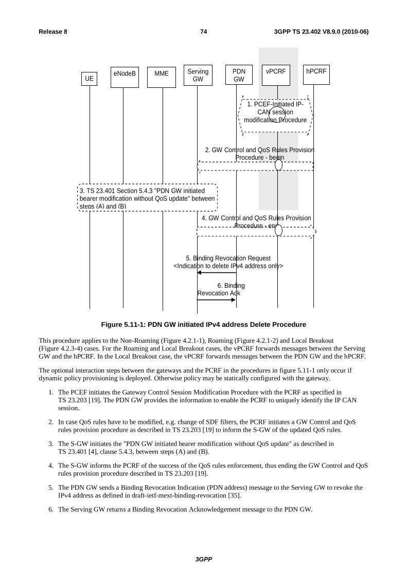
3GPP
3GPP TS 23.402 V8.9.0 (2010-06) 74Release 8
UE
5. Binding Revocation Request <Indication to delete IPv4 address only>
6. Binding Revocation Ack
PDN GW
eNodeB MME Serving GW
vPCRF hPCRF
1. PCEF-Initiated IP-CAN session
modification Procedure
2. GW Control and QoS Rules Provision Procedure - begin
3. TS 23.401 Section 5.4.3 "PDN GW initiated bearer modification without QoS update" between steps (A) and (B)
4. GW Control and QoS Rules Provision Procedure - end
Figure 5.11-1: PDN GW initiated IPv4 address Delete Procedure
This procedure applies to the Non-Roaming (Figure 4.2.1-1), Roaming (Figure 4.2.1-2) and Local Breakout (Figure 4.2.3-4) cases. For the Roaming and Local Breakout cases, the vPCRF forwards messages between the Serving GW and the hPCRF. In the Local Breakout case, the vPCRF forwards messages between the PDN GW and the hPCRF.
The optional interaction steps between the gateways and the PCRF in the procedures in figure 5.11-1 only occur if dynamic policy provisioning is deployed. Otherwise policy may be statically configured with the gateway.
1. The PCEF initiates the Gateway Control Session Modification Procedure with the PCRF as specified in TS 23.203 [19]. The PDN GW provides the information to enable the PCRF to uniquely identify the IP CAN session.
2. In case QoS rules have to be modified, e.g. change of SDF filters, the PCRF initiates a GW Control and QoS rules provision procedure as described in TS 23.203 [19] to inform the S-GW of the updated QoS rules.
3. The S-GW initiates the "PDN GW initiated bearer modification without QoS update" as described in TS 23.401 [4], clause 5.4.3, between steps (A) and (B).
4. The S-GW informs the PCRF of the success of the QoS rules enforcement, thus ending the GW Control and QoS rules provision procedure described in TS 23.203 [19].
5. The PDN GW sends a Binding Revocation Indication (PDN address) message to the Serving GW to revoke the IPv4 address as defined in draft-ietf-mext-binding-revocation [35].
6. The Serving GW returns a Binding Revocation Acknowledgement message to the PDN GW.
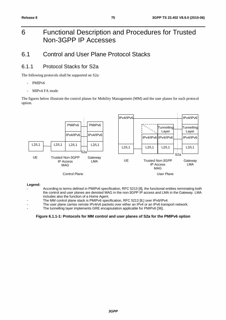
3GPP
3GPP TS 23.402 V8.9.0 (2010-06) 75Release 8
6 Functional Description and Procedures for Trusted Non-3GPP IP Accesses
6.1 Control and User Plane Protocol Stacks
6.1.1 Protocol Stacks for S2a The following protocols shall be supported on S2a:
- PMIPv6
- MIPv4 FA mode
The figures below illustrate the control planes for Mobility Management (MM) and the user planes for each protocol option.
S2a Trusted Non-3GPP
IP Access MAG
Gateway LMA
IPv4/IPv6
L2/L1
PMIPv6
IPv4/IPv6
L2/L1
PMIPv6
L2/L1
IPv4/IPv6
L2/L1
Tunnelling Layer
L2/L1 L2/L1
UE
L2/L1
IPv4/IPv6
IPv4/IPv6
L2/L1
Tunnelling Layer
IPv4/IPv6
IPv4/IPv6
S2a
Trusted Non-3GPP IP Access
MAG
Gateway LMA
UE
Control Plane User Plane
Legend: - According to terms defined in PMIPv6 specification, RFC 5213 [8], the functional entities terminating both
the control and user planes are denoted MAG in the non-3GPP IP access and LMA in the Gateway. LMA includes also the function of a Home Agent.
- The MM control plane stack is PMIPv6 specification, RFC 5213 [8,] over IPv6/IPv4. - The user plane carries remote IPv4/v6 packets over either an IPv4 or an IPv6 transport network. - The tunnelling layer implements GRE encapsulation applicable for PMIPv6 [36].
Figure 6.1.1-1: Protocols for MM control and user planes of S2a for the PMIPv6 option

3GPP
3GPP TS 23.402 V8.9.0 (2010-06) 76Release 8
S2a
Trusted Non-3GPP IP Access
FA
Gateway HA
L2/L1
IPv4
L2/L1
Tunnelling Layer
UE
L2/L1
IPv4
IPv4
L2/L1
Tunnelling Layer
IPv4
IPv4
S2a
Trusted Non-3GPP IP Access
FA
Gateway HA
UE
Control Plane User Plane
IPv4
L2/L1
UDP
MIPv4
IPv4
L2/L1
UDP
MIPv4
IPv4
L2/L1
UDP
MIPv4
IPv4
L2/L1
UDP
MIPv4
Legend: - According to terms defined in MIPv4 RFC 3344 [12], the functional entities terminating both the control and
user planes are denoted MN (Mobile Node) in the UE, FA (Foreign Agent) in the non-3GPP IP access, and HA (Home Agent) in the Gateway.
- The MM control plane stack is MIPv4 RFC 3344 [12] over UDP over IPv4. - The user plane carries remote IPv4 packets over an IPv4 transport network. - The tunnelling layer implements IP encapsulation applicable for MIPv4 as defined in RFC 3344 [12]. In
some cases the tunnelling layer may be transparent. Figure 6.1.1-2: Protocols for MM control and user planes of S2a for the MIPv4 FA mode option
6.1.2 Protocol Stacks for S2c over Trusted Non-3GPP IP Accesses The following protocol shall be supported on S2c over Trusted Non-3GPP IP Accesses:
- DSMIPv6, with IPsec and IKEv2 used to secure mobility signalling, as specified in RFC 4877 [22]
The figure below illustrates the control plane for Mobility Management (MM) and the user plane.
S2c
IP Access System Router
Gateway HA
UE
IPv4/IPv6
L2/L1
Tunnelling Layer
IPv4/IPv6
L2/L1
IPv4/IPv6
L2/L1
IPv4/IPv6
S2c
IP Access System Router
Gateway HA
UE
Control Plane User Plane
IPv4/IPv6
L2/L1
DSMIPv6
IPv4/IPv6
L2/L1
DSMIPv6
IPv4/IPv6
L2/L1
IPv4/IPv6
L2/L1
IPv4/IPv6
L2/L1
Tunnelling Layer
IPv4/IPv6
Legend: - According to terms defined in DSMIPv6 [10], the functional entities terminating both the control and user
planes are denoted MN (Mobile Node) in the UE, and HA (Home Agent) in the Gateway. - The MM control plane stack is DSMIPv6 [10] over IPv6/IPv4. - The user plane carries remote IPv4/v6 packets over either an IPv4 or an IPv6 transport network. - The tunnelling layer implements IP encapsulation applicable for MIPv6 as defined in DSMIPv6 [10]. In
some cases the tunnelling layer may be transparent.
Figure 6.1.2-1: Protocols for MM control and user planes of S2c for the DSMIPv6 option

3GPP
3GPP TS 23.402 V8.9.0 (2010-06) 77Release 8
6.2 Initial Attach on S2a
6.2.1 Initial Attach Procedure with PMIPv6 on S2a and Anchoring in PDN GW
PMIPv6 specification, RFC 5213 [8], is used to setup a PMIPv6 tunnel between the trusted non-3GPP IP access and the PDN GW. In both roaming and non-roaming cases, S2a is present. It is assumed that MAG exists in the trusted non-3GPP IP access.
Roaming Scenarios
UE vPCRF AAA Proxy
PDN GW
HSS/ AAA hPCRF
5. Proxy Binding Update
Trusted Non-3GPP IP Access
2. Authentication & Authorization
7. Update PDN GW Address
2. EAP Authentication
1. Non-3GPP Specific Procedures
3. L3 Attach Trigger
11. L3 Attach Completion
9. PMIP Tunnel
8. Proxy Binding Ack
4. Gateway Control Session Establishment Procedure
6. IP-CAN Session Establishment Procedure
10. Gateway Control and QoS Rules Provison Procedure
Figure 6.2.1-1: Initial attachment with Network-based MM mechanism over S2a for roaming, LBO and non-roaming scenarios
The optional interaction steps between the gateways and the PCRF in the procedures only occur if dynamic policy provisioning is deployed. Otherwise policy may be statically configured in the gateway.
This procedure applies to the Non-Roaming (Figure 4.2.2-1), Roaming (Figure 4.2.3-1) and Local Breakout (Figure 4.2.3-4) cases. For the Roaming and Local Breakout cases, the vPCRF forwards messages between the non-3GPP access and the hPCRF. In the Local Breakout case, the vPCRF forwards messages between the PDN GW and the hPCRF. In the Roaming and LBO cases, the 3GPP AAA Proxy serves as an intermediary between the Trusted Non-3GPP IP Access and the 3GPP AAA Server in the HPLMN. In the non-roaming case, the vPCRF is not involved at all.
1) The initial Non-3GPP access specific L2 procedures are performed. These procedures are Non-3GPP access specific and are outside the scope of 3GPP.
2) The EAP authentication procedure is initiated and performed involving the UE, Trusted Non-3GPP IP Access and the 3GPP AAA Server. In the roaming case, there may be several AAA proxies involved. Subscription data is provided to the Trusted non-3GPP IP Access by the HSS/AAA in this step. The list of all the authorized APNs along with additional PDN GW selection information is returned to the access gateway as part of the reply from the 3GPP AAA Server to the trusted non-3GPP access as described in clause 4.5.1. The 3GPP AAA Server also

3GPP
3GPP TS 23.402 V8.9.0 (2010-06) 78Release 8
returns to the trusted non-3GPP access the MN NAI to be used to identify the UE in Proxy Binding Update and Gateway Control Session Establishment messages (steps 4 and 10). If supported by Non-3GPP access network, the Attach Type is indicated to the Non-3GPP access network by the UE. The mechanism for supporting attach type is access technology specific and out of scope for 3GPP standardization. Attach Type indicates "Handover" when the UE already has active PDN connection(s) due to mobility from 3GPP access to non-3GPP access.
NOTE 1: The MN NAI returned from the 3GPP AAA Server to the trusted non-3GPP access is a permanent IMSI based MN NAI.
3) After successful authentication and authorization, the non-3GPP access specific L3 attach procedure is triggered. The UE may send requested APN to the Non-3GPP IP access in this step.
If the UE sends a requested APN in this step, the Trusted non-3GPP Access verifies that it is allowed by subscription. If the UE does not send a requested APN the Trusted non-3GPP Access uses the default APN.
The PDN Gateway selection takes place at this point as described in clause 4.5.1. This may entail an additional interaction with the Domain Name Server function in order to obtain the PDN GW address. If the PDN subscription profile returned by the 3GPP AAA Server in step 2 contains a PDN GW identity for the selected APN and the Attach Type does not indicate "Handover", the Non-3GPP access GW may request a new PDN GW as described in clause 4.5.1, e.g. to allocate a PDN GW that allows for more efficient routeing.
The UE may request the type of address (IPv4 address or IPv6 prefix or both) during this step.
If supported by the non-3GPP access, the UE may send Protocol Configuration Options in this step using access specific mechanisms. The Protocol Configuration Options provided by the UE may include the user credentials for PDN access authorization. In that case, in order to handle situations where the UE may have subscriptions to multiple PDNs, the UE should also send a requested APN to the non-3GPP IP access.
4) The Trusted non-3GPP access initiates the Gateway Control Session Establishment Procedure with the PCRF, as specified in TS 23.203 [19]. The Trusted non-3GPP access provides the information to the PCRF to correctly associate it with the IP-CAN session to be established in step 6 and also to convey subscription related parameters to the PCRF, including the APN-AMBR (if forwarded by the trusted non-3GPP IP access) and Default Bearer QoS.
5) The MAG function of Trusted Non-3GPP IP Access sends a Proxy Binding Update (MN-NAI, Lifetime, Access Technology Type, Handover Indicator, APN, GRE key for downlink traffic, Charging Characteristics, Additional Parameters) message to PDN GW. The MN NAI identifies the UE. The Lifetime field must be set to a nonzero value. Access Technology Type is set to a value matching the characteristics of the non-3GPP access. Handover Indicator is set to "initial" attach as the UE has provided Attach Type indicating "Initial" attach. The Additional Parameters include the Protocol Configuration Options provided by the UE in step 3 and may also include other information. The MAG requests the IP address types (IPv4 address and/or IPv6 Home Network Prefix) based on requested IP address types and subscription profile in the same way as the PDN type is selected during the E-UTRAN Initial Attach in TS 23.401 [4]. If the PDN requires an additional authentication and authorization with an external AAA Server, the PDN GW performs such an additional authentication and authorization at the reception of the Proxy Binding Update.
NOTE 2: Any time after initiation of Step 4, Step 5 can be initiated by MAG.
6) The PDN GW initiates the IP-CAN Session Establishment Procedure with the PCRF, as specified in TS 23.203 [19]. The PDN GW provides information to the PCRF used to identify the session and associate Gateway Control Sessions established in step 4 correctly. The PCRF creates IP-CAN session related information and responds to the PDN GW with PCC rules and event triggers. The PCRF may modify the APN-AMBR and send the APN-AMBR to the PDN GW in the response message.
7) The selected PDN GW informs the 3GPP AAA Server of its PDN GW identity and the APN corresponding to the UE's PDN Connection. The message includes information that identifies the PLMN in which the PDN GW is located. This information is registered in the HSS as described in clause 12.
8) The PDN GW processes the proxy binding update and creates a binding cache entry for the UE. The PDN GW allocates IP address(es) for the UE. The PDN GW then sends a Proxy Binding Acknowledgement (MN NAI, Lifetime, UE Address Info, GRE key for uplink traffic, charging ID, Additional Parameters) message to the MAG function in Trusted Non-3GPP IP Access, including the IP address(es) allocated for the UE. The UE Address Info includes one or more IP addresses. The Lifetime indicates the duration of the binding. The

3GPP
3GPP TS 23.402 V8.9.0 (2010-06) 79Release 8
Charging ID is assigned for the PDN connection for charging correlation purposes. The Additional Parameters may include Protocol Configuration Options and other information.
NOTE 3: If UE requests for both IPv4 and IPv6 addresses, both are allocated. If the PDN GW operator dictates the use of IPv4 addressing only or IPv6 addressing only for this APN, the PDN GW shall allocate only IPv4 address or only IPv6 prefix to the UE. If the UE requests for only IPv4 or IPv6 address only one address is allocated accordingly.
9) The PMIPv6 tunnel is set up between the Trusted Non-3GPP IP Access and the PDN GW.
10) The PCRF may update the QoS rules in the trusted non-3GPP access by initiating the GW Control Session Modification Procedure, as specified in TS 23.203 [19].
11) L3 attach procedure is completed via non-3GPP access specific trigger. IP connectivity between the UE and the PDN GW is set for uplink and downlink directions. At this step the IP address information is provided to the UE. Unless already known from step 3, the Non-3GPP IP access should indicate the connected PDN identity (APN) to the UE. If supported by the non-3GPP access, the Protocol Configuration Options provided by the PDN GW in step 8 are returned to the UE in this step using access specific mechanisms.
6.2.2 Void
6.2.3 Initial Attach procedure with MIPv4 FACoA on S2a and Anchoring in PDN-GW
MIPv4 [12] is used to setup a MIP tunnel between the Trusted non-3GPP IP Access and the PDN GW. It is assumed that a Foreign Agent (FA) is located in the Trusted non-3GPP IP Access.
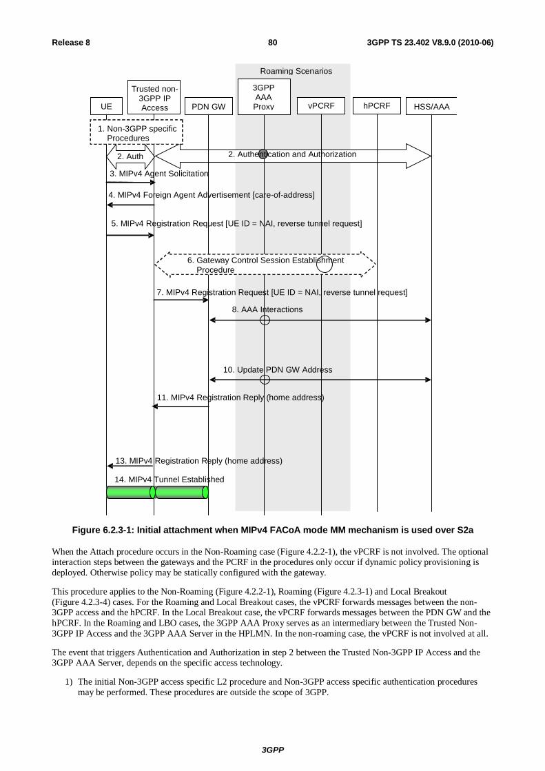
3GPP
3GPP TS 23.402 V8.9.0 (2010-06) 80Release 8
UE PDN GW
3GPP AAA Proxy
Trusted non- 3GPP IP Access vPCRF hPCRF HSS/AAA
1. Non-3GPP specific Procedures
2. Authentication and Authorization
Roaming Scenarios
2. Auth
3. MIPv4 Agent Solicitation
4. MIPv4 Foreign Agent Advertisement [care-of-address]
5. MIPv4 Registration Request [UE ID = NAI, reverse tunnel request]
7. MIPv4 Registration Request [UE ID = NAI, reverse tunnel request]
11. MIPv4 Registration Reply (home address)
10. Update PDN GW Address
13. MIPv4 Registration Reply (home address)
14. MIPv4 Tunnel Established
8. AAA Interactions
6. Gateway Control Session Establishment Procedure
Figure 6.2.3-1: Initial attachment when MIPv4 FACoA mode MM mechanism is used over S2a
When the Attach procedure occurs in the Non-Roaming case (Figure 4.2.2-1), the vPCRF is not involved. The optional interaction steps between the gateways and the PCRF in the procedures only occur if dynamic policy provisioning is deployed. Otherwise policy may be statically configured with the gateway.
This procedure applies to the Non-Roaming (Figure 4.2.2-1), Roaming (Figure 4.2.3-1) and Local Breakout (Figure 4.2.3-4) cases. For the Roaming and Local Breakout cases, the vPCRF forwards messages between the non-3GPP access and the hPCRF. In the Local Breakout case, the vPCRF forwards messages between the PDN GW and the hPCRF. In the Roaming and LBO cases, the 3GPP AAA Proxy serves as an intermediary between the Trusted Non-3GPP IP Access and the 3GPP AAA Server in the HPLMN. In the non-roaming case, the vPCRF is not involved at all.
The event that triggers Authentication and Authorization in step 2 between the Trusted Non-3GPP IP Access and the 3GPP AAA Server, depends on the specific access technology.
1) The initial Non-3GPP access specific L2 procedure and Non-3GPP access specific authentication procedures may be performed. These procedures are outside the scope of 3GPP.

3GPP
3GPP TS 23.402 V8.9.0 (2010-06) 81Release 8
2) The EAP-based authentication procedure for trusted non-3GPP access networks between UE and the 3GPP EPC shall be performed as defined by TS 33.402 [45]. The PDN Gateway information is returned as part of the reply from the 3GPP AAA Server to the FA in the trusted non-3GPP access as described in clause 4.5.1. The Attach Type is indicated to the Non-3GPP access network by the UE as described in the step 2 of clause 6.2.1.
3) The UE may send an Agent Solicitation (AS) RFC 3344 [12] message. Specification of this message is out of the scope of 3GPP.
4) The FA in the Trusted Non-3GPP IP Access sends a Foreign Agent Advertisement (FAA) [12] message to the UE. The FAA message includes the Care-of Address (CoA) of the Foreign Agent function in the FA. Specification of this message is out of the scope of 3GPP.
5) The UE sends a Registration Request (RRQ) (MN-NAI, lifetime, APN) message to the FA as specified in RFC 3344 [12]. The MN NAI identifies the UE. Reverse Tunnelling shall be requested. This ensures that all traffic will go through the PDN GW. The RRQ message shall include the NAI-Extension RFC 2794 [34]. The UE may not indicate a specific Home Agent address in the RRQ message, in which case the PDN Gateway/Home Agent is selected by the FA as per step 2. The UE then receives the IP address of the PDN Gateway in step 13 as part of the Registration Reply (RRP) message. The UE should then include the PDN Gateway address in the Home Agent address field of subsequent RRQ messages. Subscription data is provided to the Trusted non-3GPP IP Access by the HSS/AAA in this step. The UE may request connectivity to a specific PDN by using an APN as specified in RFC 5446 [39]. If the UE provides an APN the FA verifies that it is allowed by subscription. If the UE does not provide an APN the FA establishes connectivity with the default PDN. The PDN Gateway selection takes place at this point as described in clause 4.5.1. This may entail an additional name resolution step.
6) The Trusted non-3GPP access initiates the Gateway Control Session Establishment Procedure with the PCRF, as specified in TS 23.203 [19]. The Trusted non-3GPP access provides the information to the PCRF to correctly associate it with the IP-CAN session to be established in Step 9 and also to convey subscription related parameters to the PCRF, including the APN-AMBR (if forwarded by the trusted non-3GPP IP access) and Default Bearer QoS.
7) The FA processes the message according to RFC 3344 [12] and forwards a corresponding RRQ (MN-NAI, APN) message to the PDN GW.
8) The selected PDN GW obtains Authentication and Authorization information from the 3GPP AAA/HSS.
9) The PDN GW allocates an IP address for the UE. The PDN GW initiates the IP-CAN Session Establishment Procedure with the PCRF, as specified in TS 23.203 [19]. The PDN GW provides information to the PCRF used to identify the session and associate Gateway Control Sessions established in step 6 correctly. The PCRF creates IP-CAN session related information and responds to the PDN GW with PCC rules and event triggers.
10) The selected PDN GW informs the 3GPP AAA Server of the PDN GW identity and the APN corresponding to the UE's PDN Connection. The message includes information that identifies the PLMN in which the PDN GW is located. This information is registered in the HSS as described in clause 12.
11) The PDN GW sends a RRP (MN-NAI, Home Address, Home Agent Address, Lifetime) as defined in RFC 3344 [12] to the FA. The Home Address includes UE Home IP address, the Home Agent Address contains the IP address of Home Agent. The Lifetime indicates the duration of the binding.
12) In case the QoS rules have changed, the PCRF updates the QoS rules in the Trusted non-3GPP access by initiating the GW Control Session Modification Procedure, as specified in TS 23.203 [19].
13) The FA processes the RRP (MN-NAI, Home Address, Home Agent Address) according to RFC 3344 [12] and sends a corresponding RRP message to the UE.
14) IP connectivity from the UE to the PDN GW is now setup. A MIPv4 tunnel is established between the FA in the Trusted Non-3GPP IP Access and the PDN GW.
6.2.4 Initial Attach Procedure with PMIPv6 on S2a and Chained S2a and PMIP-based S8
This clause defines the initial attach procedure for the PMIP-based S8/S2a chaining. This procedure also applies to the initial attach for PMIP-based S8/S2b chaining.

3GPP
3GPP TS 23.402 V8.9.0 (2010-06) 82Release 8
UE vPCRF AAA Proxy
PDN GW
HSS/ AAA hPCRF
2. Proxy Binding Update
Trusted Non-3GPP
Access/ePDG
.
5. Update PDN GW Address
S-GW
3. Proxy Binding Update
6. Proxy Binding Ack
8. Complete Attach
PMIP Tunnel
PMIP Tunnel
1. Attach Initiation
7. Proxy Binding Ack
4. PCEF-Initiated IP-CAN Session Establishment Procedure
Figure 6.2.4-1: Initial attachment for chained PMIP-based S8-S2a/b roaming scenarios
1) The attach initiation on the trusted or untrusted non-3GPP access is performed as described in steps 1-4 of clause 6.2.1 (for trusted non-3GPP access) and step 1 of clause 7.2.1 (for untrusted non-3GPP access). As part of the authentication procedure, the 3GPP AAA proxy obtains the PDN GW selection information from the HSS/AAA as described in clause 4.5.1, and performs Serving GW selection as described in clause 4.5.3. The 3GPP AAA proxy provides both PDN GW selection information and Serving GW identity to the MAG function of the trusted non-3GPP access or ePDG. Then the MAG function performs the PDN GW selection. If PCC is deployed, the MAG function of the Trusted Non-3GPP IP access is notified to interact with the PCRF when it is PMIP-based chained case.
2) The MAG function of Trusted Non-3GPP IP Access or ePDG sends a Proxy Binding Update (MN-NAI, Lifetime, Access Technology Type, Handover Indicator, APN, GRE key for downlink traffic, PDN GW address, Additional Parameters) message to the Serving GW in the VPLMN. The MN NAI identifies the UE. The Lifetime field must be set to a nonzero value, indicating registration. Access Technology Type is set to a value matching the characteristics of the non-3GPP access. Handover Indicator is set to indicate attachment over a new interface. The MAG requests the IP address types (IPv4 address and/or IPv6 Home Network Prefix) based on requested IP address types and subscription profile in the same way as the PDN type is selected during the E-UTRAN Initial Attach in TS 23.401 [4]. The Additional Parameters may include Protocol Configuration Options and other information.
3) The Serving GW sends a corresponding Proxy Binding Update (MN-NAI, Lifetime, Access Technology Type, Handover Indicator, APN, GRE key for downlink traffic, Additional Parameters) message (as in step 2) to the PDN GW. The GRE key for downlink traffic is allocated by the Serving GW.
NOTE 1: In this Release of the specification, the Serving GW uses the right protocol to connect with the PDN GW based on the pre-configured information on itself in case the selected Serving GW supporting both PMIP and GTP.

3GPP
3GPP TS 23.402 V8.9.0 (2010-06) 83Release 8
4) The PDN GW initiates the PCEF-initiated IP CAN Session Establishment Procedure with the hPCRF, as specified in TS 23.203 [19].
5) The selected PDN GW informs the 3GPP AAA Server of the PDN GW identity. The message includes information that identifies the PLMN in which the PDN GW is located. The 3GPP AAA Server then conveys this information to the HSS for the UE.
6) The PDN GW processes the proxy binding update and allocates IP address(es) for the UE. The PDN GW creates a binding cache entry for the PMIPv6 tunnel towards the Serving GW and sends a Proxy Binding Acknowledgement (MN NAI, Lifetime, UE Address Info, GRE key for uplink traffic, Charging ID, Additional Parameters) message to the Serving GW. The MN NAI is identical to the MN NAI sent in the Proxy Binding Update. The Lifetime indicates the duration the binding will remain valid. The UE Address Info includes one or more IP addresses. The Charging ID is assigned for the PDN connection for charging correlation purposes. The Additional Parameters may include Protocol Configuration Options and other information.
NOTE 2: If UE requests for both IPv4 and IPv6 addresses, both are allocated. If the UE requests for only IPv4 or IPv6 address only one address is allocated accordingly.
7) The Serving GW processes the proxy binding acknowledgement and creates a binding cache entry for the PMIPv6 tunnel towards the MAG function in the trusted non-3GPP access or ePDG. At this point, the Serving GW also establishes the internal forwarding state for the concatenation of the PMIPv6 tunnels. The Serving GW then sends a corresponding Proxy Binding Acknowledgement (MN NAI, Lifetime, UE Address Info, GRE key for uplink traffic, Charging ID, Additional Parameters) message (as in step 7) to the MAG function of Trusted Non-3GPP IP Access or ePDG. The GRE key for uplink traffic is allocated by the Serving GW. The Charging ID is assigned for the PDN connection for charging correlation purposes.
8) The attach procedure is completed as described in steps 10-11 of clause 6.2.1 (for trusted non-3GPP access) and steps 6-8 of clause 7.2.1 (for untrusted non-3GPP access).
6.3 Initial Attach Procedure with DSMIPv6 on S2c in Trusted Non-3GPP IP Access
This clause is related to the case when the UE attaches to a Trusted Non-3GPP Access network and host based mobility management mechanisms are used. Dual Stack MIPv6 [10] is used for supporting mobility over S2c interface.
The S2c initial attach can be seen to consist of several modules:
A. The UE sets up local IP connectivity in a Trusted Non-3GPP Access
B. The UE discovers the HA, and establishes a security association with it to protect DSMIPv6 signalling.
C. The UE performs a Binding Update with the PDN GW

3GPP
3GPP TS 23.402 V8.9.0 (2010-06) 84Release 8
Roaming Scenarios
UE AAA Proxy vPCRF
PDN GW
HSS/ AAA hPCRF
5. Binding Update
Trusted Non-3GPP IP Access
7. Binding Acknowledgement
1. Access Authentication 1. Authentication and Authorization
2. L3 Attach and Local IP Address Allocation
4. Authentication and Authorization 4. MIPv6 Security Association Setup
A)
B)
C)
3. Gateway Control Session Establishment Procedure
6. IP-CAN Session Establishment Procedure
8. Gateway Control and QoS Rules Provision Procedure
Figure 6.3-1: Initial attachment from Trusted Non-3GPP IP Access with DSMIPv6
Non-roaming (Figure 4.2.2-1), home routed roaming (Figure 4.2.3-1) and Local Breakout (Figure 4.2.3-4) cases are supported by this procedure. The AAA proxy and vPCRF are only used in the case of home routed roaming and Local Breakout. In non-roaming scenarios, the AAA proxy and vPCRF are not involved.
The optional interaction steps between the gateways and the PCRF in the procedures only occur if dynamic policy provisioning is deployed. Otherwise policy may be statically configured in the gateway.
The UE may be authenticated and authorised to access the Trusted Non-3GPP Access network according to an access network specific procedure. These procedures are outside the scope of 3GPP, After the authentication, UE is configured with Local IP Address from the access network domain.
A) Setup of Local IP connectivity
1) Access Authentication procedure for trusted Non-3GPP access networks between UE and the 3GPP EPC shall be performed as defined by TS 33.402 [45] unless the conditions in TS 33.402 are met that allow to skip this procedure As indicated above, in the roaming case signalling may be routed via a 3GPP AAA Proxy in the VPLMN, as specified in TS 23.234 [5]. As part of the AAA exchange for network access authentication, the AAA/HSS and/or the 3GPP AAA Proxy may return to the Trusted non-3GPP IP Access a set of home/visited operator's policies to be enforced on the usage of local IP address, or IPv6 prefix, allocated by the access system upon successful authentication. Subscription data is provided to the Trusted non-3GPP IP Access by the HSS/AAA in this step.
2) The L3 connection is established between the UE and the Trusted Non-3GPP Access system. As a result of this procedure, an IPv4 address or an IPv6 address/prefix is also assigned to the UE by the access system (i.e. a Local IP address that will be used as a Care-of Address for DSMIPv6 over the S2c reference point).
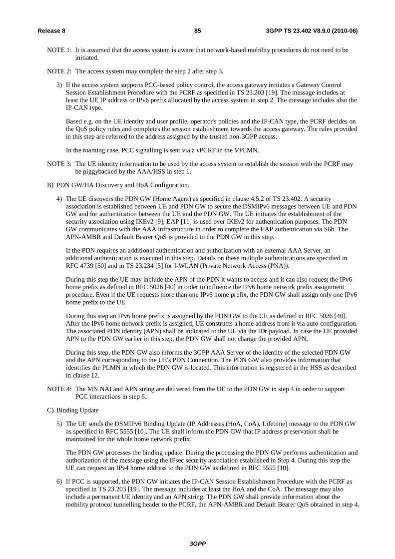
3GPP
3GPP TS 23.402 V8.9.0 (2010-06) 85Release 8
NOTE 1: It is assumed that the access system is aware that network-based mobility procedures do not need to be initiated.
NOTE 2: The access system may complete the step 2 after step 3.
3) If the access system supports PCC-based policy control, the access gateway initiates a Gateway Control Session Establishment Procedure with the PCRF as specified in TS 23.203 [19]. The message includes at least the UE IP address or IPv6 prefix allocated by the access system in step 2. The message includes also the IP-CAN type.
Based e.g. on the UE identity and user profile, operator's policies and the IP-CAN type, the PCRF decides on the QoS policy rules and completes the session establishment towards the access gateway. The rules provided in this step are referred to the address assigned by the trusted non-3GPP access.
In the roaming case, PCC signalling is sent via a vPCRF in the VPLMN.
NOTE 3: The UE identity information to be used by the access system to establish the session with the PCRF may be piggybacked by the AAA/HSS in step 1.
B) PDN GW/HA Discovery and HoA Configuration.
4) The UE discovers the PDN GW (Home Agent) as specified in clause 4.5.2 of TS 23.402. A security association is established between UE and PDN GW to secure the DSMIPv6 messages between UE and PDN GW and for authentication between the UE and the PDN GW. The UE initiates the establishment of the security association using IKEv2 [9]; EAP [11] is used over IKEv2 for authentication purposes. The PDN GW communicates with the AAA infrastructure in order to complete the EAP authentication via S6b. The APN-AMBR and Default Bearer QoS is provided to the PDN GW in this step.
If the PDN requires an additional authentication and authorization with an external AAA Server, an additional authentication is executed in this step. Details on these multiple authentications are specified in RFC 4739 [50] and in TS 23.234 [5] for I-WLAN (Private Network Access (PNA)).
During this step the UE may include the APN of the PDN it wants to access and it can also request the IPv6 home prefix as defined in RFC 5026 [40] in order to influence the IPv6 home network prefix assignment procedure. Even if the UE requests more than one IPv6 home prefix, the PDN GW shall assign only one IPv6 home prefix to the UE.
During this step an IPv6 home prefix is assigned by the PDN GW to the UE as defined in RFC 5026 [40]. After the IPv6 home network prefix is assigned, UE constructs a home address from it via auto-configuration. The associated PDN identity (APN) shall be indicated to the UE via the IDr payload. In case the UE provided APN to the PDN GW earlier in this step, the PDN GW shall not change the provided APN.
During this step, the PDN GW also informs the 3GPP AAA Server of the identity of the selected PDN GW and the APN corresponding to the UE's PDN Connection. The PDN GW also provides information that identifies the PLMN in which the PDN GW is located. This information is registered in the HSS as described in clause 12.
NOTE 4: The MN NAI and APN string are delivered from the UE to the PDN GW in step 4 in order to support PCC interactions in step 6.
C) Binding Update
5) The UE sends the DSMIPv6 Binding Update (IP Addresses (HoA, CoA), Lifetime) message to the PDN GW as specified in RFC 5555 [10]. The UE shall inform the PDN GW that IP address preservation shall be maintained for the whole home network prefix.
The PDN GW processes the binding update. During the processing the PDN GW performs authentication and authorization of the message using the IPsec security association established in Step 4. During this step the UE can request an IPv4 home address to the PDN GW as defined in RFC 5555 [10].
6) If PCC is supported, the PDN GW initiates the IP-CAN Session Establishment Procedure with the PCRF as specified in TS 23.203 [19]. The message includes at least the HoA and the CoA. The message may also include a permanent UE identity and an APN string. The PDN GW shall provide information about the mobility protocol tunnelling header to the PCRF, the APN-AMBR and Default Bearer QoS obtained in step 4.

3GPP
3GPP TS 23.402 V8.9.0 (2010-06) 86Release 8
The PCRF decides on the PCC rules and Event Triggers and provisions them to the PDN GW. The PDN GW installs the received PCC rules.
NOTE 5: The permanent UE identity to be used by the PDN GW to establish the session with the PCRF may be piggybacked by the AAA/HSS in step 4.
7) The PDN GW sends the DSMIPv6 Binding Ack (Lifetime, IP Addresses (HoA, CoA)) message to the UE. In this step the PDN GW may include the duration of the binding and the IPv4 home address allocated for the UE as specified in RFC 5555 [10], if previously requested by the UE and allowed by the subscription profile as it is specified in the E-UTRAN attach procedure in TS 23.401 [4]. Even in case the UE requests more than one IPv4 home address in step 5, the PDN GW shall assign only one IPv4 home address for the UE.
8) The PCRF initiates the Gateway Control and QoS Rules Provision Procedure specified in TS 23.203 [19] by sending a message with the information of mobility protocol tunnelling encapsulation header to the Trusted non 3GPP access Gateway. In case the QoS rules have changed, the updated QoS rules shall also be included in this message.
NOTE 6: Rules related to the HoA can be sent to the Trusted Non-3GPP Access based on the procedure in clause 6.6.2.
6.4 Detach and PDN Disconnection for S2a
6.4.1 UE/Trusted Non-3GPP IP Access Network Initiated Detach and UE/Trusted Non-3GPP IP Access requested PDN Disconnection Procedure with PMIPv6
6.4.1.1 Non-Roaming, Home Routed Roaming and Local Breakout Case
The procedure in this clause applies to both Detach Procedures, including UE or Trusted non-3GPP access initiated detach procedure, and UE/Trusted non-3GPP Access requested PDN disconnection procedure when supported by the Trusted non-3GPP access.
The UE can initiate the detach procedure, e.g. when the UE is power off. The Trusted Non-3GPP Access Network can initiate the detach procedure due to administrative reasons or detecting the UE's leaving by, e.g. Link-layer event specific to the access technology (refer to PMIPv6 specification, RFC 5213 [8], for more information).

3GPP
3GPP TS 23.402 V8.9.0 (2010-06) 87Release 8
Roaming Scenarios
UE AAA Proxy vPCRF
PDN GW
HSS/ AAA hPCRF
3. Proxy Binding Update (lifetime=0)
Trusted Non-3GPP IP Access
6. Proxy Binding Ack
1. Access technology specific detach trigger
4. Update PDN GW Address
7. Non-3GPP specific resource release
procedure
2. Gateway Control Session Termination Procedure
5. PCEF-Initiated IP-CAN Session Termination Procedure
Figure 6.4.1.1-1: UE/Trusted Non-3GPP Access Network initiated detach procedure or PDN-disconnection with PMIPv6
For detach procedure and in case of connectivity with multiple PDNs, the steps 2 to 6 are repeated for each PDN the UE is connected to.
For UE-requested PDN disconnection procedure, steps 2 to 6 are performed for the PDN that the UE requested disconnection from.
This procedure applies to the Non-Roaming (Figure 4.2.2-1), Roaming (Figure 4.2.3-1) and Local Breakout (Figure 4.2.3-4) cases. For the Roaming and Local Breakout cases, the vPCRF forwards messages between the non-3GPP access and the hPCRF. In the Local Breakout case, the vPCRF forwards messages between the PDN GW and the hPCRF. In the Roaming and LBO cases, the 3GPP AAA Proxy serves as an intermediary between the Trusted Non-3GPP IP Access and the 3GPP AAA Server in the HPLMN. In the non-roaming case, the vPCRF is not involved at all.
If dynamic policy provisioning is not deployed, the optional steps 3 and 4 do not occur. Instead, the PDN GW may employ static configured policies.
1) The UE or the Trusted Non-3GPP Access Network triggers either detach or disconnection from a specific PDN by an access technology specific procedure.
2) The Trusted Non-3GPP Access Network initiates the Gateway Control Session Termination Procedure with the PCRF as specified in TS 23.203 [19]. The Trusted Non-3GPP Access Network no longer applies QoS policy to traffic flows for this UE.
3) The Mobile Access Gateway (MAG) in the Trusted Non-3GPP IP Access sends a Proxy Binding Update (MN NAI, APN, lifetime=0) message to the PDN GW with lifetime value set to zero, indicating de-registration. The MN NAI identifies the UE to deregister from the PDN GW. The APN is needed in order to determine which PDN to deregister the UE from, as some PDN GWs may support multiple PDNs.
4) The PDN GW informs the AAA Server/HSS to remove the PDN GW identity information and APN corresponding to the UE's PDN connection. This information is de-registered from the HSS as described in clause 12.

3GPP
3GPP TS 23.402 V8.9.0 (2010-06) 88Release 8
5) The PDN GW deletes the IP CAN session associated with the UE and executes a PCEF-Initiated IP CAN Session Termination Procedure with the PCRF as specified in TS 23.203 [19].
6) The PDN GW deletes existing entries implied in the Proxy Binding Update message from its Binding Cache and sends a Proxy Binding Ack (MN NAI, APN, lifetime=0) message to the MAG.
7) Non-3GPP specific resource release procedure is executed. The resources of Trusted Non-3GPP Access Network are released. In case of disconnection from a PDN, if the PDN from which the UE is disconnected was the only PDN that the UE was connected to, detach related procedures may be performed in the Trusted non-3GPP IP access.
6.4.1.2 Chained PMIP-based S8-S2a Roaming Case
This clause defines the UE/Trusted Non-3GPP IP Access Network-initiated detach procedure UE-requested PDN disconnection procedure for PMIP-based S8-S2a chaining. This procedure also applies to UE/ePDG-initiated detach procedure for PMIP-based S8-S2b chaining.
UE AAA Proxy
vPCRF
PDN GW
HSS/ AAA hPCRF
2. Proxy Binding Update (lifetime=0)
Trusted Non-3GPP
Access/ePDG
4. Update PDN GW Address
S-GW
3. Proxy Binding Update (lifetime=0)
7. Proxy Binding Ack
6. Proxy Binding Ack
1. Detach Initiation
8. Detach Completion
5. PCEF-Initiated IP-CAN Session Termination Procedure
Figure 6.4.1.2-1: UE/ePDG/Trusted Non-3GPP Access Network initiated detach procedure for chained PMIP-based S8-S2a/b roaming scenarios and PDN-disconnection for chained PMIP-based S8-S2a
For detach procedure and in case of connectivity with multiple PDNs, the steps 2 to 7 are repeated for each PDN the UE is connected to.
For UE-requested PDN disconnection procedure for chained PMIP-based S8-S2a, steps 2 to 7 are performed for the PDN that the UE requested disconnection from.
1) For detach, initial steps of the detach is performed as described in steps 1-2 of clause 6.4.1.1 (for trusted non-3GPP access) and step 1 of clause 7.4.1.1 (for untrusted non-3GPP access). For UE-requested PDN disconnection in chained PMIP-based S8-S2a, steps 1-2 of clause 6.4.1.1 are performed.
2) The MAG in the Trusted Non-3GPP IP Access or ePDG sends a Proxy Binding Update (MN NAI, APN, lifetime=0) message to the Serving GW with lifetime value set to zero, indicating de-registration. The MN NAI identifies the UE to deregister from the PDN GW. The APN is needed in order to determine which PDN GW to deregister the UE from, as some PDNs may support multiple PDNs.

3GPP
3GPP TS 23.402 V8.9.0 (2010-06) 89Release 8
3) The Serving GW deletes all existing entries implied in the Proxy Binding Update message from its Binding Cache and releases all associated resources (e.g. GRE tunnel), and then sends a corresponding Proxy Binding Update message (as in step 2) to the PDN GW in the HPLMN.
4) The PDN GW informs the AAA Server/HSS to remove the PDN GW address information for the UE.
5) The PDN GW initiates the PCEF-initiated IP CAN Session Termination Procedure, as specified in TS 23.203 [19].
6) The PDN GW deletes existing entries implied in the Proxy Binding Update message from its Binding Cache and releases all associated resources, and then sends a Proxy Binding Ack (MN NAI, APN, lifetime=0) message to the Serving GW in the VPLMN.
7) The Serving GW sends a corresponding Proxy Binding Ack message (as in step 6) to the MAG function in Trusted Non-3GPP IP Access.
8) The detach procedure is completed as described in step 7 of clause 6.4.1.1 (for trusted non-3GPP access) and step 6 of clause 7.4.1.1 (for untrusted non-3GPP access). In case of disconnection from a PDN, if the PDN from which the UE is disconnected was the only PDN that the UE was connected to, detach related procedures may be performed.
6.4.2 HSS/AAA Initiated Detach Procedure with PMIPv6
6.4.2.1 Non-Roaming, Home Routed Roaming and Local Breakout Case
HSS/AAA-initiated detach procedure with PMIPv6 is illustrated in figure 6.4.2.1-1. The HSS can initiate the procedure e.g. when the user's subscription is removed. The 3GPP AAA Server can initiate the procedure, e.g. instruction from O&M, timer for re-authentication/re-authorization expired.
Roaming Scenarios
UE AAA Proxy vPCRF
PDN GW
HSS/ AAA hPCRF
1. UE De-registration Request
3. UE De-Registration Ack
2. The procedures as TS 23.402, Figure 6.4.1.1-1, after Step 1
Trusted Non-3GPP IP Access
Figure 6.4.2.1-1: HSS/AAA-initiated detach procedure with PMIPv6
This procedure applies to the Non-Roaming (Figure 4.2.2-1), Roaming (Figure 4.2.3-1) and Local Breakout (Figure 4.2.3-4) cases. For the Roaming and Local Breakout cases, the vPCRF forwards messages between the non-3GPP access and the hPCRF. In the Local Breakout case, the vPCRF forwards messages between the PDN GW and the hPCRF. In the Roaming and LBO cases, the 3GPP AAA Proxy serves as an intermediary between the Trusted Non-3GPP IP Access and the 3GPP AAA Server in the HPLMN. In the non-roaming case, the vPCRF is not involved at all.
1) The HSS/AAA sends a Detach Indication message to the MAG in the Trusted Non-3GPP Access Network to detach a specific UE.
2) This includes the procedure after step 1 as in figure 6.4.1.1-1.
3) The MAG of the Trusted Non-3GPP Access Network sends a Detach Ack message to the HSS/AAA.
NOTE: The HSS/AAA may also send a detach indication message to the PDN GW. The PDN GW does not remove the PMIP tunnels on S2a, since the MAG in the non-3GPP access is responsible for removing the PMIP tunnels on S2a. The PDN GW acknowledges the receipt of the detach indication message to the HSS/AAA.

3GPP
3GPP TS 23.402 V8.9.0 (2010-06) 90Release 8
6.4.2.2 Chained PMIP-based S8-S2a Roaming Case
This clause defines the HSS/AAA-initiated detach procedure for PMIP-based S8-S2a chaining. This procedure also applies for PMIP-based S8-S2b chaining.
UE AAA Proxy vPCRF
PDNGW
HSS/AAA hPCRF
1. Detach Indication
3. Detach Ack
2. Detach Procedures
Trusted Non-3GPP IP Access/ePDG S-GW
Figure 6.4.2.2-1: HSS/AAA-initiated detach procedure for chained PMIP-based S8-S2a/b roaming scenarios
1) The HSS/AAA sends a Detach Indication message to the MAG in the Trusted Non-3GPP Access Network or ePDG to detach a specific UE.
2) The detach procedure as described in steps 2-7 of clause 6.4.1.1 is performed for trusted non-3GPP accesses and according to steps 2-6 of clause 7.4.1.1 for untrusted non-3GPP accesses.
3) The MAG of the Trusted Non-3GPP Access Network or ePDG sends a Detach Ack message to the HSS/AAA.
NOTE: The HSS/AAA may also send a detach indication message to the PDN GW. The PDN GW does not remove the PMIP tunnels on S2a, since the MAG in the non-3GPP access is responsible for removing the PMIP tunnels on S2a. The PDN GW acknowledges the receipt of the detach indication message to the HSS/AAA.

3GPP
3GPP TS 23.402 V8.9.0 (2010-06) 91Release 8
6.4.3 UE-initiated Detach Procedure and UE-Requested PDN Disconnection Procedure with MIPv4 FACoA
The procedure in this clause applies to both UE initiated Detach Procedure and UE-requested PDN disconnection procedure with MIPv4 FACoA when supported by the Trusted non-3GPP access.
The UE can initiate this procedure, e.g. when the UE is powered off.
Roaming Scenarios
UE AAA Proxy vPCRF
PDN GW
HSS/ AAA hPCRF
3. MIPv4 Registration Request (lifetime=0))
Trusted Non-3GPP IP Access
7. MIPv4 Registration Reply
5. Update PDN GW Address
9. Non-3GPP specific resource release procedure
1. MIPv4 Registration Request (lifetime=0)
8. MIPv4 Registration Reply
2. Gateway Control Session Termination Procedure
6. PCEF-Initiated IP-CAN Session Termination Procedure
4. AAA Interactions
Figure 6.4.3-1: UE-initiated detach procedure with MIPv4 FACoA
NOTE: AAA proxy and vPCRF are only used in the case of home routed roaming (Figure 4.2.3-1) and local breakout (Figure 4.2.3-4).
For detach procedure and in case of connectivity with multiple PDNs, the steps 1 to 9 are repeated for each PDN the UE is connected to.
For UE-requested PDN disconnection procedure, steps 1 to 9 are performed for the PDN that the UE requested disconnection from.
The optional interaction steps between the gateways and the PCRF in the procedures only occur if dynamic policy provisioning is deployed. Otherwise policy may be statically configured with the gateway.
This procedure applies to the Non-Roaming (Figure 4.2.2-1), Roaming (Figure 4.2.3-1) and Local Breakout (Figure 4.2.3-4) cases. For the Roaming and Local Breakout cases, the vPCRF forwards messages between the non-3GPP access and the hPCRF. In the Local Breakout case, the vPCRF forwards messages between the PDN GW and the hPCRF. In the Roaming and LBO cases, the 3GPP AAA Proxy serves as an intermediary between the Trusted Non-3GPP IP Access and the 3GPP AAA Server in the HPLMN. In the non-roaming case, the vPCRF is not involved at all.
1) The UE sends a MIPv4 Registration Request (RRQ) (MN-NAI, Home Address, Home Agent Address, Care-of Address, lifetime = 0) message to the Foreign Agent (FA) in the Trusted Non-3GPP Access Network with lifetime value set to zero, indicating de-registration. The MN-NAI identifies the UE. The Home Address includes UE Home IP addresses, the Home Agent Address contains the IP address of Home Agent. Care-of Address indicates the CoA used by the UE for the binding.

3GPP
3GPP TS 23.402 V8.9.0 (2010-06) 92Release 8
2) The Trusted Non-3GPP Access Network initiates the Gateway Control Session Termination Procedure with the PCRF as specified in TS 23.203 [19]. The Trusted Non-3GPP Access Network no longer applies QoS policy to traffic flows for this UE.
3) The FA relays this MIPv4 RRQ (MN-NAI, lifetime = 0) message to the PDN GW.
4) The selected PDN GW obtains Authentication and Authorization information from the AAA/HSS.
5) The PDN GW informs the AAA Server/HSS to remove the PDN GW identity information and APN corresponding to the UE's PDN Connection. This information is de-registered from the HSS as described in clause 12.
6) The PDN GW deletes the IP CAN session associated with the UE and executes a PCEF-Initiated IP-CAN Session Termination Procedure with the PCRF as specified in TS 23.203 [19].
7) The PDN GW sends a MIPv4 Registration Reply (RRP) (MN-NAI, Home Address, Home Agent Address, Lifetime=0) message to the FA.
8) Any time after step 7, the FA relays this MIPv4 RRP (MN-NAI, Home Address, Home Agent Address, Lifetime=0) message to the UE.
9) After step 7, Non-3GPP specific resource release procedure is executed.
6.4.4 Network Initiated Detach Procedure with MIPv4 FACoA Trusted Non-3GPP Access Network initiated detach procedure with MIPv4 FACoA Mode is illustrated in Figure 6.4.4-1. The Trusted Non-3GPP Access Network can initiate this procedure due to administration reason or detecting the UE's leaving by, e.g. Link-layer event specific to the access technology (see RFC 3543 [25] for more information).
Roaming Scenarios
UE AAA Proxy vPCRF
PDN GW
HSS/ AAA hPCRF
2. Registration Revocation
Trusted Non-3GPP IP Access
5. Registration Revocation Ack
3. Update PDN GW Address
6. Non-3GPP specific resource release procedure
1. Gateway Control Session Termination Procedure
4. PCEF-Initiated IP-CAN Session Termination Procedure
Figure 6.4.4-1: Trusted Non-3GPP Access Network initiated detach procedure with MIPv4 FACoA
NOTE: AAA proxy and vPCRF are only used in the case of home routed roaming (Figure 4.2.3-1) and local breakout (Figure 4.2.3-4).

3GPP
3GPP TS 23.402 V8.9.0 (2010-06) 93Release 8
The optional interaction steps between the gateways and the PCRF in the procedures only occur if dynamic policy provisioning is deployed. Otherwise policy may be statically configured with the gateway.
This procedure applies to the Non-Roaming (Figure 4.2.2-1), Roaming (Figure 4.2.3-1) and Local Breakout (Figure 4.2.3-4) cases. For the Roaming and Local Breakout cases, the vPCRF forwards messages between the non-3GPP access and the hPCRF. In the Local Breakout case, the vPCRF forwards messages between the PDN GW and the hPCRF. In the Roaming and LBO cases, the 3GPP AAA Proxy serves as an intermediary between the Trusted Non-3GPP IP Access and the 3GPP AAA Server in the HPLMN. In the non-roaming case, the vPCRF is not involved at all.
1) The Trusted Non-3GPP Access Network detects the UE's leaving and initiates a Gateway Control Session Termination Procedure with the PCRF as specified in TS 23.203 [19]. The Trusted Non-3GPP Access Network no longer applies QoS policy to traffic flows for this UE.
2) The FA sends a Registration Revocation (Home Address, Home Agent Address, Care-of Address) message (see RFC 3543 [25]) to the PDN GW.
3) The PDN GW informs the AAA Server/HSS to remove the PDN GW identity information and APN corresponding to the UE's PDN Connection. This information is de-registered from the HSS as described in clause 12.
4) The PDN GW deletes the IP CAN session associated with the UE and executes a PCEF-Initiated IP-CAN Session Termination Procedure with the PCRF as specified in TS 23.203 [19].
5) The PDN GW sends a Registration Revocation Ack (Home Address) message (see RFC 3543 [25]) to the FA.
6) The Trusted Non-3GPP Access Network executes a specific resource release procedure.
6.4.5 HSS/AAA-initiated detach procedure with MIPv4 FACoA HSS/AAA-initiated detach procedure with MIPv4 FACoA Mode is illustrated in Figure 6.4.5-1. The HSS can initiate the procedure e.g. when the user's subscription is removed. The 3GPP AAA Server can initiate the procedure, e.g. instruction from O&M, timer for re-authentication/re-authorization expired.
Roaming Scenarios
UE AAA Proxy vPCRF
PDN GW
HSS/ AAA hPCRF
Trusted Non-3GPP IP Access
1. Detach Indication
3. Detach Ack
2. Procedure as TS 23.402, Figure 6.4.4-1
Figure 6.4.5-1: HSS/AAA-initiated detach procedure with MIPv4 FACoA
NOTE: AAA proxy and vPCRF are only used in the case of home routed roaming (Figure 4.2.3-1) and local breakout (Figure 4.2.3-4).
The optional interaction steps between the gateways and the PCRF in the procedures only occur if dynamic policy provisioning is deployed. Otherwise policy may be statically configured with the gateway.
This procedure applies to the Non-Roaming (Figure 4.2.2-1), Roaming (Figure 4.2.3-1) and Local Breakout (Figure 4.2.3-4) cases. For the Roaming and Local Breakout cases, the vPCRF forwards messages between the non-3GPP access and the hPCRF. In the Local Breakout case, the vPCRF forwards messages between the PDN GW and the hPCRF. In the Roaming and LBO cases, the 3GPP AAA Proxy serves as an intermediary between the Trusted Non-3GPP IP Access and the 3GPP AAA Server in the HPLMN. In the non-roaming case, the vPCRF is not involved at all.

3GPP
3GPP TS 23.402 V8.9.0 (2010-06) 94Release 8
1) The HSS/AAA sends a detach indication message to the FA in the Trusted Non-3GPP Access Network to detach a specific UE.
2) This includes the procedure in figure 6.4.4-1.
3) The FA sends a Detach Ack message to the HSS/AAA.
NOTE: The HSS/AAA may also send a detach indication message to the PDN GW. The PDN GW does not remove the MIPv4 tunnels, since the MIPv4 FA in the non-3GPP access is responsible for removing the MIPv4 tunnels. The PDN GW acknowledges the receipt of the detach indication message to the HSS/AAA.
6.5 Detach and PDN Disconnection for S2c in Trusted Non-3GPP IP Access
6.5.1 General This clause is related to the cases where at least one DSMIPv6 PDN disconnection procedure is performed. In case of detach the DSMIPv6 PDN disconnection is executed for all the existing PDNs connections, while in the case of disconnecting a single PDN connection the DSMIPv6 PDN disconnection is executed only for the individual PDN connection.
The DSMIPv6 PDN disconnection procedure is on a per PDN basis and allows:
- the UE to inform the network that it requests to release a S2c based PDN connection, and
- the network to inform the UE that a S2c based PDN connection is disconnected.
The UE may be disconnected from a PDN either explicitly or implicitly:
- Explicit PDN disconnection: The network or the UE explicitly requests PDN disconnection and signal with each other.
- Implicit PDN disconnection: The network disconnects the UE from a PDN, without notifying the UE. This is typically the case when the network presumes that it is not able to communicate with the UE, e.g. due to radio conditions.
Three PDN disconnection procedures are provided when the UE accesses the EPS through S2c:
- UE-Initiated PDN disconnection Procedure;
- AAA/HSS-initiated Detach Procedure;
- PDN GW-initiated PDN disconnection Procedure.
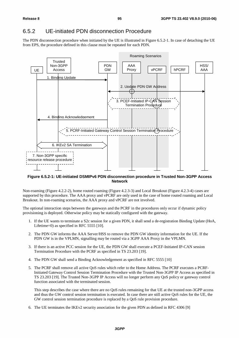
3GPP
3GPP TS 23.402 V8.9.0 (2010-06) 95Release 8
6.5.2 UE-initiated PDN disconnection Procedure The PDN disconnection procedure when initiated by the UE is illustrated in Figure 6.5.2-1. In case of detaching the UE from EPS, the procedure defined in this clause must be repeated for each PDN.
Roaming Scenarios
UE AAA Proxy vPCRF
PDN GW
HSS/ AAA hPCRF
1. Binding Update
Trusted Non-3GPP
Access
4. Binding Acknowledgement
2. Update PDN GW Address
3. PCEF-Initiated IP-CAN Session Termination Procedure
5. PCRF-Initiated Gateway Control Session Termination Procedure
6. IKEv2 SA Termination
7. Non-3GPP specific resource release procedure
Figure 6.5.2-1: UE-initiated DSMIPv6 PDN disconnection procedure in Trusted Non-3GPP Access Network
Non-roaming (Figure 4.2.2-2), home routed roaming (Figure 4.2.3-3) and Local Breakout (Figure 4.2.3-4) cases are supported by this procedure. The AAA proxy and vPCRF are only used in the case of home routed roaming and Local Breakout. In non-roaming scenarios, the AAA proxy and vPCRF are not involved.
The optional interaction steps between the gateways and the PCRF in the procedures only occur if dynamic policy provisioning is deployed. Otherwise policy may be statically configured with the gateway.
1. If the UE wants to terminate a S2c session for a given PDN, it shall send a de-registration Binding Update (HoA, Lifetime=0) as specified in RFC 5555 [10].
2. The PDN GW informs the AAA Server/HSS to remove the PDN GW identity information for the UE. If the PDN GW is in the VPLMN, signalling may be routed via a 3GPP AAA Proxy in the VPLMN.
3. If there is an active PCC session for the UE, the PDN GW shall execute a PCEF-Initiated IP-CAN session Termination Procedure with the PCRF as specified in TS 23.203 [19].
4. The PDN GW shall send a Binding Acknowledgement as specified in RFC 5555 [10]
5. The PCRF shall remove all active QoS rules which refer to the Home Address. The PCRF executes a PCRF-Initiated Gateway Control Session Termination Procedure with the Trusted Non-3GPP IP Access as specified in TS 23.203 [19]. The Trusted Non-3GPP IP Access will no longer perform any QoS policy or gateway control function associated with the terminated session.
This step describes the case where there are no QoS rules remaining for that UE at the trusted non-3GPP access and thus the GW control session termination is executed. In case there are still active QoS rules for the UE, the GW control session termination procedure is replaced by a QoS rule provision procedure.
6. The UE terminates the IKEv2 security association for the given PDN as defined in RFC 4306 [9]
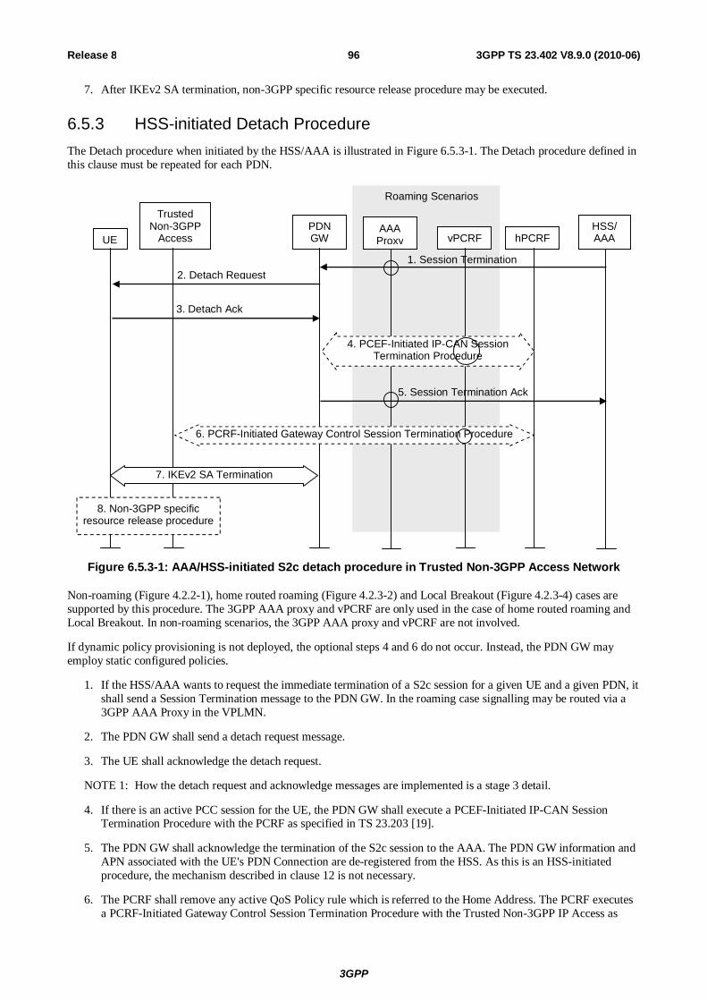
3GPP
3GPP TS 23.402 V8.9.0 (2010-06) 96Release 8
7. After IKEv2 SA termination, non-3GPP specific resource release procedure may be executed.
6.5.3 HSS-initiated Detach Procedure The Detach procedure when initiated by the HSS/AAA is illustrated in Figure 6.5.3-1. The Detach procedure defined in this clause must be repeated for each PDN.
Roaming Scenarios
UE AAA Proxy vPCRF
PDN GW
HSS/ AAA hPCRF
1. Session Termination
Trusted Non-3GPP
Access
2. Detach Request
5. Session Termination Ack
3. Detach Ack
4. PCEF-Initiated IP-CAN Session Termination Procedure
6. PCRF-Initiated Gateway Control Session Termination Procedure
7. IKEv2 SA Termination
8. Non-3GPP specific resource release procedure
Figure 6.5.3-1: AAA/HSS-initiated S2c detach procedure in Trusted Non-3GPP Access Network
Non-roaming (Figure 4.2.2-1), home routed roaming (Figure 4.2.3-2) and Local Breakout (Figure 4.2.3-4) cases are supported by this procedure. The 3GPP AAA proxy and vPCRF are only used in the case of home routed roaming and Local Breakout. In non-roaming scenarios, the 3GPP AAA proxy and vPCRF are not involved.
If dynamic policy provisioning is not deployed, the optional steps 4 and 6 do not occur. Instead, the PDN GW may employ static configured policies.
1. If the HSS/AAA wants to request the immediate termination of a S2c session for a given UE and a given PDN, it shall send a Session Termination message to the PDN GW. In the roaming case signalling may be routed via a 3GPP AAA Proxy in the VPLMN.
2. The PDN GW shall send a detach request message.
3. The UE shall acknowledge the detach request.
NOTE 1: How the detach request and acknowledge messages are implemented is a stage 3 detail.
4. If there is an active PCC session for the UE, the PDN GW shall execute a PCEF-Initiated IP-CAN Session Termination Procedure with the PCRF as specified in TS 23.203 [19].
5. The PDN GW shall acknowledge the termination of the S2c session to the AAA. The PDN GW information and APN associated with the UE's PDN Connection are de-registered from the HSS. As this is an HSS-initiated procedure, the mechanism described in clause 12 is not necessary.
6. The PCRF shall remove any active QoS Policy rule which is referred to the Home Address. The PCRF executes a PCRF-Initiated Gateway Control Session Termination Procedure with the Trusted Non-3GPP IP Access as

3GPP
3GPP TS 23.402 V8.9.0 (2010-06) 97Release 8
specified in TS 23.203 [19]. The Trusted Non-3GPP IP Access will no longer perform any QoS policy or gateway control function associated with the terminated session.
This step describes the case where there are no QoS rules remaining for that UE at the trusted non-3GPP access and thus the GW control session termination is executed. In case there are still active QoS rules for the UE, the GW control session termination procedure is replaced by a QoS rule provision procedure.
7. The PDN GW or the UE terminates the IKEv2 security association for the given PDN as defined in RFC 4306 [9].
8. After IKEv2 SA termination, non-3GPP specific resource release procedure may be executed.
NOTE 2: The HSS/AAA may (e.g.. when STa is implemented and/or based on operator's policies) also send a detach indication message to the non-3GPP access. The HSS/AAA should wait to receive acknowledgement(s) from PDN GW(s) before sending the detach indication to the non-3GPP access. The non-3GPP access detaches the UE and acknowledges the receipt of the detach indication message to the HSS/AAA.
6.5.4 PDN-GW-initiated PDN Disconnection Procedure The PDN Disconnection procedure when initiated by the PDN-GW is illustrated in Figure 6.5.4-1.
Roaming Scenarios
UE AAA Proxy vPCRF
PDN GW
HSS/ AAA hPCRF
Trusted Non-3GPP
Access
1. PDN Disconnection Request
2. PDN Disconnection Ack
4. PCEF-Initiated IP-CAN Session Termination Procedure
6. IKEv2 SA Termination
3. Update PDN GW Address
5. Gateway Control and QoS Rules Provision or PCRF-Initiated Gateway Control Session Termination Procedure
7. Non-3GPP specific resource release procedure
Figure 6.5.4-1: PDN GW Initiated PDN disconnection S2c procedure in Trusted Non-3GPP Access Network
Non-roaming (Figure 4.2.2-1), home routed roaming (Figure 4.2.3-2) and Local Breakout (Figure 4.2.3-4) cases are supported by this procedure. The 3GPP AAA proxy and vPCRF are only used in the case of home routed roaming and Local Breakout. In non-roaming scenarios, the 3GPP AAA proxy and vPCRF are not involved.
If dynamic policy provisioning is not deployed, the optional step 3 does not occur. Instead, the PDN GW may employ static configured policies.
If the PDN GW-initiated PDN Disconnection Procedure is triggered by the UE binding lifetime expiration (Implicit PDN disconnection procedure), steps 1 and 2 may be omitted.

3GPP
3GPP TS 23.402 V8.9.0 (2010-06) 98Release 8
1. In the explicit detach procedure the PDN GW shall send a detach request message.
2. In the explicit detach procedure, the UE shall acknowledge the detach request.
NOTE: How the detach request and acknowledge messages are implemented is a stage 3 detail.
3. If this is the last PDN connection for the given APN, the PDN GW informs the AAA Server/HSS to remove the PDN GW identity information for the UE. If the PDN GW is in the VPLMN, signalling may be routed via a 3GPP AAA Proxy in the VPLMN.
4. If there is an active PCC session for the UE, the PDN GW shall execute a PCEF-Initiated IP-CAN Session Termination Procedure with the PCRF as specified in TS 23.203 [19].
5. The PCRF shall remove all active QoS rules which refer to the Home Address. The PCRF executes a Gateway Control and QoS Rules Provision procedure or, if this is the last PDN Connection for the UE, a PCRF-Initiated Gateway Control Session Termination Procedure with the Trusted Non-3GPP IP Access as specified in TS 23.203 [19]. The Trusted Non-3GPP IP Access will no longer perform any QoS policy or gateway control function associated with the terminated PDN Connection.
6. The PDN GW or the UE may terminate the IKEv2 security association for the given PDN as defined in RFC 4306 [9].
7. After IKEv2 SA termination, non-3GPP specific resource release procedure may be executed.
6.6 Network-initiated Dynamic PCC
6.6.1 Network-initiated Dynamic PCC on S2a If dynamic PCC is deployed, the procedure given in Figure 6.6.1-1 is used by the PCRF to provision rules to the Trusted non-3GPP IP access and for the Trusted non-3GPP IP access to enforce the policy by controlling the resources and configuration in the trusted non-3GPP access. The access specific procedure executed in the trusted non-3GPP access is not within the scope of this specification.
Trusted Non-3GPP
IP Access PDN GW vPCRF hPCRF
2. Access specific mechanism to
enforce the policy
Roaming Scenarios
4. PCC Rules Provision Procedure
3. Gateway Control and QoS Policy Rules Provision- end
1. Gateway Control and QoS Policy Rules Provision- begin
Figure 6.6.1-1: Network-initiated dynamic policy control procedure in Trusted Non-3GPP IP Access for S2a
This procedure concerns both the non-roaming (as Figure 4.2.2-1) and roaming case (as Figure 4.2.3-1). In the roaming case, the vPCRF in the VPLMN forwards messages between the Trusted Non-3GPP IP Access and the hPCRF in the HPLMN. In the case of Local Breakout (as Figure 4.2.3-4), the vPCRF forwards messages sent between the PDN GW and the hPCRF. In the non-roaming case, the vPCRF is not involved at all.
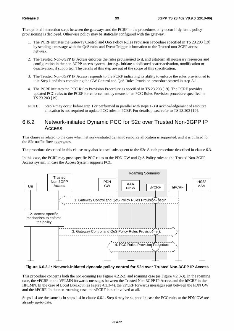
3GPP
3GPP TS 23.402 V8.9.0 (2010-06) 99Release 8
The optional interaction steps between the gateways and the PCRF in the procedures only occur if dynamic policy provisioning is deployed. Otherwise policy may be statically configured with the gateway.
1. The PCRF initiates the Gateway Control and QoS Policy Rules Provision Procedure specified in TS 23.203 [19] by sending a message with the QoS rules and Event Trigger information to the Trusted non-3GPP access network..
2. The Trusted Non-3GPP IP Access enforces the rules provisioned to it, and establish all necessary resources and configuration in the non-3GPP access system, ,for e.g.. initiate a dedicated bearer activation, modification or deactivation, if supported. The details of this step are out of the scope of this specification.
3. The Trusted Non-3GPP IP Access responds to the PCRF indicating its ability to enforce the rules provisioned to it in Step 1 and thus completing the GW Control and QoS Rules Provision procedure started in step A.1.
4. The PCRF initiates the PCC Rules Provision Procedure as specified in TS 23.203 [19]. The PCRF provides updated PCC rules to the PCEF for enforcement by means of an PCC Rules Provision procedure specified in TS 23.203 [19].
NOTE: Step 4 may occur before step 1 or performed in parallel with steps 1-3 if acknowledgement of resource allocation is not required to update PCC rules in PCEF. For details please refer to TS 23.203 [19].
6.6.2 Network-initiated Dynamic PCC for S2c over Trusted Non-3GPP IP Access
This clause is related to the case when network-initiated dynamic resource allocation is supported, and it is utilized for the S2c traffic flow aggregates.
The procedure described in this clause may also be used subsequent to the S2c Attach procedure described in clause 6.3.
In this case, the PCRF may push specific PCC rules to the PDN GW and QoS Policy rules to the Trusted Non-3GPP Access system, in case the Access System supports PCC.
Roaming Scenarios
UE AAA Proxy vPCRF
PDN GW
HSS/ AAA hPCRF
Trusted Non-3GPP
Access
2. Access specific mechanism to enforce
the policy
1. Gateway Control and QoS Policy Rules Provision- begin
4. PCC Rules Provision Procedure
3. Gateway Control and QoS Policy Rules Provision- end
Figure 6.6.2-1: Network-initiated dynamic policy control for S2c over Trusted Non-3GPP IP Access
This procedure concerns both the non-roaming (as Figure 4.2.2-2) and roaming case (as Figure 4.2.3-3). In the roaming case, the vPCRF in the VPLMN forwards messages between the Trusted Non-3GPP IP Access and the hPCRF in the HPLMN. In the case of Local Breakout (as Figure 4.2.3-4), the vPCRF forwards messages sent between the PDN GW and the hPCRF. In the non-roaming case, the vPCRF is not involved at all.
Steps 1-4 are the same as in steps 1-4 in clause 6.6.1. Step 4 may be skipped in case the PCC rules at the PDN GW are already up-to-date.

3GPP
3GPP TS 23.402 V8.9.0 (2010-06) 100Release 8
6.7 UE-initiated Resource Request and Release
6.7.1 UE-initiated Resource Request and Release on S2a This procedure is applicable to both PMIPv6 on S2a and DSMIPv6 on S2c.
This clause is related to the case when UE-initiated resource request and release is supported in the Trusted Non-3GPP IP Access, and it is utilized for the S2a/S2c traffic flow aggregates.
Figure 6.7.1-1 depicts the procedure for the roaming and non-roaming cases.
1. IP-CAN specific resource request/release initiated by UE
Roaming Scenarios
3. Access specific mechanism to enforce the policy
UE PDN GW vPCRF hPCRF Trusted Non-3GPP
IP Access
2. Gateway Control and QoS Rules Request -begin
5. PCC Rules Provision Procedure
4. Gateway Control and QoS Policy Rules Request - end
Figure 6.7.1-1: UE-initiated resource request/release with S2a or S2c
The optional interaction steps between the gateways and the PCRF in the procedures only occur if dynamic policy provisioning is deployed. Otherwise policy may be statically configured with the gateway.
Both the roaming (Figure 4.2.3-1) and non-roaming (Figure 4.2.2-1) scenarios are depicted in the figure. In the roaming case, the vPCRF acts as an intermediary, sending the QoS Policy Rules Provision from the hPCRF in the HPLMN to the trusted non-3GPP IP access in the VPLMN. The vPCRF receives the Acknowledgment from the trusted non-3GPP IP access and forwards it to the hPCRF. In the non-roaming case, the vPCRF is not involved at all.
1. The trusted non-3GPP IP access receives an IP-CAN specific resource allocation or resource release request initiated by the UE.
2. The trusted non-3GPP IP access initiates the Gateway Control and QoS Policy Rules Request Procedure as specified in TS 23.203 [19]. The trusted non-3GPP IP access provides the UE request or release of resources as an Event Report. The PCRF makes a PCC decision as a result of the Gateway Control and QoS policy request and provides the updated QoS Rules to the trusted non-3GPP IP access.
3. An IP-CAN specific resource allocation or resource release procedure may be triggered by the enforcement of the received policy rules. In this step, a response for the resource request/release is sent to the UE.
4. The trusted non-3GPP IP access indicates to the PCRF whether the requested QoS Policy Rules Provision could be enforced or not and thus completing the GW Control and QoS Rules Provision procedure.
5. The PCRF initiates the Policy and Charging Rules Provision Procedure as specified in TS 23.203 [19] to update the PCC rules in the PDN GW. The updated PCC Rules and Event Triggers include any adjustments to resources due to the decision taken in step 2.

3GPP
3GPP TS 23.402 V8.9.0 (2010-06) 101Release 8
NOTE: Step 5 may be performed in parallel with Steps 2-4 if acknowledgement of resource allocation is not required at the PCRF to update PCC rules in PCEF. For details please refer to TS 23.203 [19].
Step 2 may be omitted if the Trusted non-3GPP IP access has already received authorisation for the UE's request from the PCRF, e.g.. QoS rules downloaded at handover.
6.7.2 UE-initiated Resource Request for S2c over Trusted Non-3GPP IP Access
The procedure is specified in clause 6.7.1.
6.8 UE-initiated Connectivity to Additional PDN
6.8.1 UE-initiated Connectivity to Additional PDN with PMIPv6 on S2a
6.8.1.1 Non-Roaming, Home Routed Roaming and Local Breakout Case
Establishment of connectivity to an additional PDN over trusted access with S2a is supported only for the accesses that support such feature and the UEs that have such capability.
PMIPv6 specification, RFC 5213 [8], is used to setup an IP connectivity between the trusted non-3GPP IP access and the EPC during initial attach. In both roaming and non-roaming cases, S2a is present. It is assumed that MAG exists in the trusted non-3GPP IP access.
NOTE 1: The PDN GW treats each MN-ID+APN as a separate binding and may allocate a new IP address/prefix for each binding.
One PDN connection per APN is supported. If the UE requests a PDN connection for an APN for which the UE already has an active PDN connection, the trusted non-3GPP IP access shall reject the PDN connectivity request.
The procedure is also used for the re-establishment of existing PDN connectivity after the UE performed the handover from 3GPP accesses for the first PDN connection by the Attach procedure.

3GPP
3GPP TS 23.402 V8.9.0 (2010-06) 102Release 8
UE Trusted Non-3GPP IP
Access (MAG) PDN GW
PDN GW 2 vPCRF hPCRF
HSS/AAA AAA
Proxy
Roaming Scenarios
Existing PMIP Tunnel 4. New PMIP Tunnel
Existing PMIP Tunnel
1. Trigger new PDN Connectivity
3. Reply(new PDN connectivity information)
2. Steps 4-10 of Figure 6.2.1-1
Figure 6.8.1.1-1: Additional PDN connectivity with Network-based MM mechanism over S2a for non-roaming and roaming
The steps in the procedure which are marked as optional occur only if dynamic policy provisioning has been deployed.
In the roaming case, messages are forwarded between the Trusted Non-3GPP IP Access and the hPCRF via the vPCRF. In the case of LBO, messages are forwarded between the PDN GW and the hPCRF via the vPCRF also. Further, in the case of LBO, messages between the PDN GW and the 3GPP AAA Server are sent via the 3GPP AAA Proxy.
1) When the UE wishes to connect to an additional PDN, it sends a trigger indicating that connectivity with that specific PDN is desired. The UE provides information about the new PDN by using an APN. If supported by the non-3GPP access, the UE may send Protocol Configuration Options in this step using access specific mechanisms. The Protocol Configuration Options provided by the UE may include the user credentials for PDN access authorization. The UE triggers the re-establishment of existing PDN connectivity after the handover by providing a Request Type indicating "Handover" on accesses that support the indication.
NOTE 2: The definition of the trigger that the UE provides to the access network (MAG) is out of scope of 3GPP.
2) At this step the trusted non-3GPP IP access performs PDN GW selection as described in clause 4.5.1. Steps 4 to 10 according to clause 6.2.1 are executed with PDN GW2 instead of PDN GW1.
3) The trusted non-3GPP IP access system sends the reply message to the UE with the allocated IP address from the PDN that the UE indicated at step 1. If supported by the non-3GPP access, the Protocol Configuration Options provided by the PDN GW in step 2 are returned to the UE in this step using access specific mechanisms. Since UE requested for additional PDN connectivity, the UE configures the IP address received from the MAG without deleting its configuration for connectivity with any other previously established PDN. For handover, the UE is returned the IP address the UE obtained before the handover during PDN connectivity establishment.
NOTE 3: The definition of the message used to carry the new connectivity information to the UE is out of scope of 3GPP.
4) The PMIPv6 tunnel is thus set up between the Trusted Non-3GPP IP Access and the PDN GW corresponding to the requested additional PDN while maintaining tunnels previously established for other PDNs.
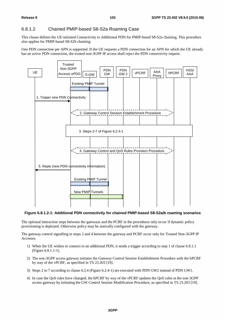
3GPP
3GPP TS 23.402 V8.9.0 (2010-06) 103Release 8
6.8.1.2 Chained PMIP-based S8-S2a Roaming Case
This clause defines the UE-initiated Connectivity to Additional PDN for PMIP-based S8-S2a chaining. This procedure also applies for PMIP-based S8-S2b chaining.
One PDN connection per APN is supported. If the UE requests a PDN connection for an APN for which the UE already has an active PDN connection, the trusted non-3GPP IP access shall reject the PDN connectivity request.
UE
Trusted Non-3GPP PDN
GW PDN GW 2 vPCRF hPCRF
HSS/ AAA AAA
Proxy
1. Trigger new PDN Connectivity
5. Reply (new PDN connectivity information)
S-GW
Existing PMIP Tunnel
Access/ ePDG
New PMIP Tunnels
Existing PMIP Tunnel
4. Gateway Control and QoS Rules Provision Procedure
2. Gateway Control Session Establishment Procedure
3. Steps 2-7 of Figure 6.2.4-1
Figure 6.8.1.2-1: Additional PDN connectivity for chained PMIP-based S8-S2a/b roaming scenarios
The optional interaction steps between the gateways and the PCRF in the procedures only occur if dynamic policy provisioning is deployed. Otherwise policy may be statically configured with the gateway.
The gateway control signalling in steps 2 and 4 between the gateway and PCRF occur only for Trusted Non-3GPP IP Accesses.
1) When the UE wishes to connect to an additional PDN, it sends a trigger according to step 1 of clause 6.8.1.1 (Figure 6.8.1.1-1).
2) The non-3GPP access gateway initiates the Gateway Control Session Establishment Procedure with the hPCRF by way of the vPCRF, as specified in TS 23.203 [19].
3) Steps 2 to 7 according to clause 6.2.4 (Figure 6.2.4-1) are executed with PDN GW2 instead of PDN GW1.
4) In case the QoS rules have changed, the hPCRF by way of the vPCRF updates the QoS rules at the non-3GPP access gateway by initiating the GW Control Session Modification Procedure, as specified in TS 23.203 [19].

3GPP
3GPP TS 23.402 V8.9.0 (2010-06) 104Release 8
5) The trusted non-3GPP access system or ePDG sends the reply message to the UE according to step 3 of clause 6.8.1.1 (Figure 6.8.1.1-1). If supported by the trusted non-3GPP access system, the Protocol Configuration Option provided by the PDN GW in step 3 are returned to the UE in this step using access specific mechanisms.
6.8.2 UE-initiated Connectivity to Additional PDN with MIPv4 FACoA on S2a
NOTE: The PDN GW treats each MN-ID+APN as a separate binding and may allocate a new IP address for each binding.
Multiple connections to the same APN is supported for MIPv4 FACoA on S2a as the UE and PDN GW distinguish between connections by means of the UE's distinct home addresses for each connection.
UE Trusted Non-3GPP IP Access (FA)
PDN GW
PDN GW 2 vPCRF hPCRF HSS/
AAA AAA Proxy
Roaming Scenarios
Existing MIPv4 Tunnel 4. New MIPv4 Tunnel
Existing MIPv4 Tunnel 1. MIPv4 Registration Request [UE ID = NAI, reverse tunnel request, Service Request Selection]
3. MIPv4 Registration Reply (home address)
2. Steps 6 – 12 of Figure 6.2.3-1
Figure 6.8.2-1: UE-initiated Connectivity to Additional PDN with MIPv4 FACoA on S2a
This procedure applies to the Non-Roaming (Figure 4.2.2-1), Roaming (Figure 4.2.3-1) and Local Breakout (Figure 4.2.3-4) cases. For the Roaming and Local Breakout cases, the vPCRF forwards messages between the non-3GPP access and the hPCRF. In the Local Breakout case, the vPCRF forwards messages between the PDN GW and the hPCRF. In the Roaming and LBO cases, the 3GPP AAA Proxy serves as an intermediary between the Trusted Non-3GPP IP Access and the 3GPP AAA Server in the HPLMN. In the non-roaming case, the vPCRF is not involved at all.
1) When the UE wishes to connect to an additional PDN, UE sends a Registration Request (RRQ) (MN-NAI, lifetime, APN) RFC 3344 [12] message to the FA as specified in RFC 3344 [12]. Reverse Tunnelling shall be requested. This ensures that all traffic will go through the PDN GW. The RRQ message shall include the NAI-Extension RFC 2794 [34]. The UE may not indicate a specific Home Agent address in the RRQ message, in which case the PDN Gateway/Home Agent is selected by the FA. The UE then receives the IP address of the PDN Gateway in step 3 as part of the Registration Reply (RRP) message. The UE should then include the PDN Gateway address in the Home Agent address field of subsequent RRQ messages. The UE provides information about the new PDN by using an APN as specified in RFC 5446 [39].
2) The trusted non-3GPP IP access performs a PDN GW selection for the new PDN connection. Steps 6-12 of clause 6.2.3 are executed with PDN GW2 instead of PDN GW1. The AAA interactions for obtaining Authentication and Authorization information occur irrespective of whether the UE has a PDN connection with a different APN to the same PDN GW or not.
3) The FA processes the RRP (MN-NAI, Home Address, Home Agent Address, APN) message according to RFC 3344 [12] and sends a corresponding RRP message to the UE.

3GPP
3GPP TS 23.402 V8.9.0 (2010-06) 105Release 8
4) The MIPv4 tunnel is thus set up between the Trusted Non-3GPP IP Access and the PDN GW2 corresponding to the requested additional PDN while maintaining tunnels previously established for other PDNs.
6.8.3 UE-initiated Connectivity to Additional PDN from Trusted Non-3GPP IP Access with DSMIPv6 on S2c
This clause is related to the case when the UE attaches to a Trusted Non-3GPP Access network and host-based mobility management mechanisms are used. Dual Stack MIPv6 [10] is used for supporting mobility over S2c interface. This case describes the scenario when UE adds connectivity to one or more additional PDN at any time after initial attach. Since host-based mobility mechanisms are used, the procedure is similar to the initial attach procedure.
NOTE: Based on the MN-ID and APN, the PDN GW may allocate a new IP address/prefix for a new binding.
UE PDN
GW1
1. S2c Attach to additional PDNs, as in steps 4 -8 of Figure 6.3-1
PDN GW2Trusted
non - 3GPP
Existing PDN connection
Figure 6.8.3-1: UE-initiated connectivity to multiple PDNs from Trusted Non-3GPP IP Access with DSMIPv6
When the initial attachment is performed, the UE performs procedures described in clause 6.3, Figure 6.3-1, to obtain connectivity with a PDN GW and a specific PDN. If at any time, the UE wants to obtain connectivity with additional PDNs, it repeats steps 4-8 of Figure 6.3-1.
1). The UE performs PDN GW discovery for the new PDN and repeats steps 4-8 of clause 6.3, Figure 6.3-1 for each additional PDN the UE wants to connect to. This step can be performed and be repeated at any time after the initial attach for one or multiple PDNs.
If the UE discovers a different PDN GW for the additional PDN connectivity, when the current PDN GW could provide access to the additional PDN, the PDN GW reallocation procedure may be used, as defined in clause 6.10.
6.9 Void
6.10 PDN GW reallocation upon attach on S2c The PDN GW reallocation procedure depicted in figure 6.10-1 can be used by the HSS/AAA to force the assignment of a new PDN GW to the UE upon attach with DSMIPv6 in a trusted or untrusted non-3GPP IP access. The decision on whether to trigger PDN GW reallocation is taken by the HSS/AAA according to the principles described in clause 4.5.2.

3GPP
3GPP TS 23.402 V8.9.0 (2010-06) 106Release 8
Roaming Scenarios
UE Initi al PDN GW
HSS/ AAA Trusted Non - 3GPP
IP Access/ePDG
2. DSMIPv6 security association setup and reallocation trigger
1. Access t o trusted non - 3GPP IP access/ePDG and CoA configuration: Figure 6.3 - 1 steps 1 - 3 (trusted access) or Figure 7.3 - 1 steps 1 - 3 (untrusted access)
Target PDN GW
Reallocation trigger and target PGW address
2. Authentication and authorization
AAA Proxy
4 . BU/BA exchange with target PDN GW: Figure 6.3 - 1 steps 5 - 8 (trusted access) or Figure 7.3 - 1 steps 5 - 7 (untrusted access)
vPCRF hPCRF
3 . DSMIPv6 security association setup, HoA configuration with target PDN GW: Figure 6.3-1 step 4 (trusted access) or Figure 7.3-1 step 4 (untrusted access)
Figure 6.10-1: PDN GW reallocation upon initial attach on S2c
The following is a detailed description of the involved steps:
1) The UE authenticates in the trusted non-3GPP access, or establishes the IPsec tunnel with the ePDG, and obtains a local IP address to be used as care-of address for DSMIPv6.
2) The UE establishes the DSMIPv6 SA with the initially discovered PDN GW. This implies an AAA exchange with the HSS/AAA. The HSS/AAA triggers the reallocation of the PDN GW and the APN associated with the UE's PDN Connection by piggybacking a reallocation indication and the target PDN GW identity in the AAA exchange. In the signalling from the PDN-GW to the UE, the PDN-GW indicates reallocation, assigns no IPv6 prefix to the UE and includes the IP address of the target PDN GW.
If the target PDN GW identity is stored in the HSS in form of the IP address, then this IP address can be transferred to the UE directly. If the target PDN GW identity is stored in the HSS in form of the PDN GW FQDN, the initial PDN GW shall derive the IP address of the HA functionality of the target PDN GW from the PDN GW FQDN provided by the AAA server and provide it to the UE.
3) The UE establishes the DSMIPv6 SA with the target PDN GW provided by the network during step 2.
4) The UE performs the DSMIPv6 registration with the target PDN GW.
NOTE 1: In case the UE performs DSMIPv6 bootstrapping for an existing PDN connection, the UE includes its IPv6 Home Address during step 2.
NOTE 2: The DSMIPv6 SA between the UE and the initial PDN GW may be implicitly removed by the UE and the initial PDN GW any time after step 2, before expiry of the SA.
6.11 S2c Bootstrapping via DSMIPv6 Home Link over a Trusted Access
When the UE is connected on a trusted non-3GPP access considered to be DSMIPv6 home link for the UE based on clause 4.5.6, the UE may trigger the establishment of S2c IKEv2 SA, e.g. to optimize future handovers to other accesses using S2c. For each PDN connection, the S2c IKEv2 SA establishment has to be performed separately.
NOTE: A trusted non-3GPP access can be defined as DSMIPv6 Home Link in addition to the 3GPP access.
Once the UE is attached to the PDN over the trusted non-3GPP access, the procedure describing the bootstrapping is in clause 15.1.

3GPP
3GPP TS 23.402 V8.9.0 (2010-06) 107Release 8
6.12 PDN GW initiated Resource Allocation Deactivation
6.12.1 PDN GW initiated Resource Allocation Deactivation with S2a PMIP This procedure is performed to release all the resources associated with the PDN address, for example, due to IP-CAN session modification requests from PCRF or due to handover Non-3GPP to 3GPP. When it is performed for a handover, the connections associated with the PDN address are released, but the PDN address is kept in the PDN GW
UE
2. Binding Revocation Request
PDN GW
hPCRF
Roaming Scenarios
vPCRF
3. Release the Old context
5. Binding Revocation Ack
Trusted Non-3GPP IP Access
Trusted Non-3GPP IP Access initiated release procedures (where applicable)
4. Gateway Control Session Termination Procedure
AAA/ HSS
3GPP AAA proxy
1. IP-CAN Session Modification
6. Update PDN GW Address
Figure 6.12.1-1: PDN GW Initiated Binding Revocation with S2a PMIP
This procedure applies to the Non-Roaming (Figure 4.2.2-1), Roaming (Figure 4.2.3-1) and Local Breakout (Figure 4.2.3-4) cases. For the Roaming and Local Breakout cases, the vPCRF forwards messages between the non-3GPP IP access and the hPCRF. In the Local Breakout case, the vPCRF forwards messages between the PDN GW and the hPCRF. In the non-roaming case, the vPCRF is not involved at all.
The optional interaction steps between the gateways and the PCRF in the procedures in figure 6.12.1-1 only occur if dynamic policy provisioning is deployed. Otherwise policy may be statically configured with the gateway.
1. If dynamic PCC is deployed, the PDN GW initiated Resource Allocation Deactivation procedure may for example be triggered due to 'IP-CAN session Modification procedure', as defined in TS 23.203 [6]. In this case the resources associated with the PDN connection in the PDN GW are released.
The PDN GW initiated Resource Allocation Deactivation can also be triggered during handovers from Non-3GPP to 3GPP.
2. The PDN GW sends a Binding Revocation Indication message to the trusted non-3GPP IP access as defined in draft-ietf-mext-binding-revocation [35].
3. The resources may be released in the trusted non-3GPP IP access, according to an access specific, trusted non-3GPP IP access initiated, release mechanism.
4. If the resources are released in the trusted non-3GPP IP access, the trusted non-3GPP IP access initiates a Gateway Control Session Termination Procedure with the PCRF as specified in TS 23.203 [19].
5. The trusted non-3GPP IP access returns a Binding Revocation Acknowledgement message to the PDN GW.
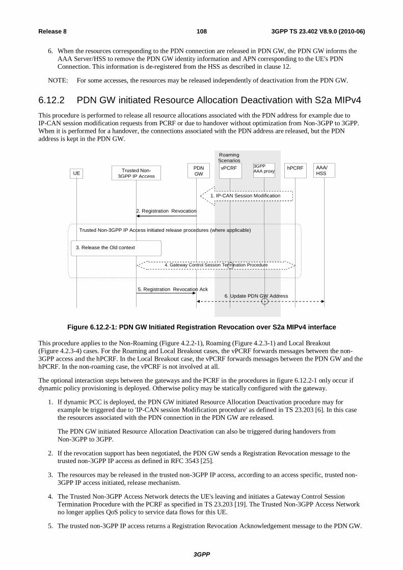
3GPP
3GPP TS 23.402 V8.9.0 (2010-06) 108Release 8
6. When the resources corresponding to the PDN connection are released in PDN GW, the PDN GW informs the AAA Server/HSS to remove the PDN GW identity information and APN corresponding to the UE's PDN Connection. This information is de-registered from the HSS as described in clause 12.
NOTE: For some accesses, the resources may be released independently of deactivation from the PDN GW.
6.12.2 PDN GW initiated Resource Allocation Deactivation with S2a MIPv4 This procedure is performed to release all resource allocations associated with the PDN address for example due to IP-CAN session modification requests from PCRF or due to handover without optimization from Non-3GPP to 3GPP. When it is performed for a handover, the connections associated with the PDN address are released, but the PDN address is kept in the PDN GW.
UE
2. Registration Revocation Request
PDN GW
hPCRF
Roaming Scenarios
vPCRF
3. Release the Old context
5. Registration Revocation Ack
Trusted Non-3GPP IP Access
Trusted Non-3GPP IP Access initiated release procedures (where applicable)
4. Gateway Control Session Termination Procedure
AAA/ HSS
3GPP AAA proxy
1. IP-CAN Session Modification
6. Update PDN GW Address
Figure 6.12.2-1: PDN GW Initiated Registration Revocation over S2a MIPv4 interface
This procedure applies to the Non-Roaming (Figure 4.2.2-1), Roaming (Figure 4.2.3-1) and Local Breakout (Figure 4.2.3-4) cases. For the Roaming and Local Breakout cases, the vPCRF forwards messages between the non-3GPP access and the hPCRF. In the Local Breakout case, the vPCRF forwards messages between the PDN GW and the hPCRF. In the non-roaming case, the vPCRF is not involved at all.
The optional interaction steps between the gateways and the PCRF in the procedures in figure 6.12.2-1 only occur if dynamic policy provisioning is deployed. Otherwise policy may be statically configured with the gateway.
1. If dynamic PCC is deployed, the PDN GW initiated Resource Allocation Deactivation procedure may for example be triggered due to 'IP-CAN session Modification procedure' as defined in TS 23.203 [6]. In this case the resources associated with the PDN connection in the PDN GW are released.
The PDN GW initiated Resource Allocation Deactivation can also be triggered during handovers from Non-3GPP to 3GPP.
2. If the revocation support has been negotiated, the PDN GW sends a Registration Revocation message to the trusted non-3GPP IP access as defined in RFC 3543 [25].
3. The resources may be released in the trusted non-3GPP IP access, according to an access specific, trusted non-3GPP IP access initiated, release mechanism.
4. The Trusted Non-3GPP Access Network detects the UE's leaving and initiates a Gateway Control Session Termination Procedure with the PCRF as specified in TS 23.203 [19]. The Trusted Non-3GPP Access Network no longer applies QoS policy to service data flows for this UE.
5. The trusted non-3GPP IP access returns a Registration Revocation Acknowledgement message to the PDN GW.

3GPP
3GPP TS 23.402 V8.9.0 (2010-06) 109Release 8
6. When the resources corresponding to the PDN connection are released in PDN GW, the PDN GW informs the AAA Server/HSS to remove the PDN GW identity information and APN corresponding to the UE's PDN Connection. This information is de-registered from the HSS as described in clause 12.
NOTE: For some accesses, the resources may be released independently of deactivation from the PDN GW.
6.12.3 PDN GW initiated Resource Allocation Deactivation for Chained PMIP-based S8-S2a Roaming
This clause defines the PDN GW initiated resource allocation deactivation for chained PMIP-based S8-S2a roaming. This procedure also applies for PMIP-based S8-S2b chaining.
UE
2. Binding Revocation Request
PDN GW
hPCRF vPCRF
3. Release the old context
5. Binding Revocation Ack
Trusted Non-3GPP Access / ePDG
Trusted Non-3GPP IP Access or ePDG initiated release procedures (where applicable)
Serving GW
1. Binding Revocation Request
6. Binding Revocation Ack
4. Gateway Control Session Termination Procedure
AAA/ HSS
7. Update PDN GW Address
AAA Proxy
Roaming Scenarios
Figure 6.12.3-1: PDN GW Initiated Binding Revocation for Chained PMIP-based S8-S2a Roaming Case
The optional interaction step between the gateways and the PCRF in the procedures in figure 6.12.3-1 occur only if dynamic policy provisioning is deployed. Otherwise policies may be statically configured in the gateway.
1. The PDN GW sends a Binding Revocation Indication message to the MAG function in the Serving GW as defined in draft-ietf-mext-binding-revocation [35].
2. The Serving GW sends a corresponding Binding Revocation Indication message to the MAG function of the trusted non-3GPP IP access or ePDG.
3. The trusted non-3GPP IP access or ePDG may release allocated resources in the non-3GPP IP access according to access specific release mechanisms.
4. In case a Gateway Control Session between the trusted non-3GPP access or ePDG and hPCRF exists, the Gateway Control Session Termination procedure, as specified in TS 23.203 [19], is performed.
5. The MAG function of the trusted non-3GPP IP access or ePDG returns a Binding Revocation Acknowledgement message to the Serving GW.
6. The MAG function of the Serving GW or ePDG sends a corresponding Binding Revocation Acknowledgement message to the PDN GW.
7. In the case where the resources corresponding to the PDN connection are released in the PDN GW, the PDN GW informs the AAA Server/HSS to remove the PDN GW identity information and APN corresponding to the UE's PDN Connection. This information is de-registered from the HSS as described in clause 12.

3GPP
3GPP TS 23.402 V8.9.0 (2010-06) 110Release 8
NOTE: For some accesses, the resources may be released independently of deactivation from the PDN GW.
6.12.4 Void
6.13 PDN GW initiated IPv4 address Delete Procedure This procedure is initiated by the PDN GW when the UE releases the IPv4 address using DHCPv4 procedure or the lease for the IP address has expired. The procedure is used to delete the IPv4 address from the PDN connection bearer context.
UE
5. Binding Revocation Indication, (Indication to delete IPv4 address only)
6. Binding Revocation Acknowledgement
PDN GW
Trusted non-3GPP
Access vPCRF hPCRF
1. PCEF-Initiated IP-CAN session
modification Procedure
2. GW Control and QoS Rules Provision Procedure - begin
3. Access Specific mechanism for modification of context according to the rule.
4. GW Control and QoS Rules Provision Procedure - end
Figure 6.13-1: PDN GW initiated IPv4 address Delete Procedure
The optional interaction steps between the gateways and the PCRF in the procedures only occur if dynamic policy provisioning is deployed. Otherwise policy may be statically configured in the gateway.
The roaming (Figure 4.2.3-1), Local Breakout (Figure 4.2.3-4) and non-roaming (Figure 4.2.2-1) scenarios are depicted in the figure. In the roaming case, the vPCRF acts as an intermediary, relaying the PCC messages between the hPCRF in the HPLMN to the BBERF/PCEF in the VPLMN. In the non-roaming case, the vPCRF is not involved at all. In the Roaming and LBO cases, the 3GPP AAA Proxy serves as an intermediary between the Trusted Non-3GPP IP Access and the 3GPP AAA Server in the HPLMN.
1. The PCEF initiates the IP-CAN Session Modification Procedure with the PCRF as specified in TS 23.203 19]. The PDN GW provides the information to enable the PCRF to uniquely identify the IP-CAN session.
2. In case QoS rules have to be modified, e.g. change of SDF filters, the PCRF initiates a GW Control and QoS rules provision procedure as described in TS 23.203 [19] to inform the Trusted non-3GPP access of the updated QoS rules.

3GPP
3GPP TS 23.402 V8.9.0 (2010-06) 111Release 8
3. The Trusted non-3GPP Access initiates the "Network-initiated Dynamic PCC on S2a" procedure to release the bearers.
4. The trusted non-3GPP access informs the PCRF of the success of the QoS rules enforcement, thus ending the GW Control and QoS rules provision procedure described in TS 23.203 [19].
5. The PDN GW sends a Binding Revocation Indication (PDN address) message to the trusted non-3GPP access to revoke the IPv4 address as defined in draft-ietf-mext-binding-revocation [35].
6. The trusted non-3GPP access returns a Binding Revocation Acknowledgement message to the PDN GW.
6.14 Non-3GPP access initiated IPv4 address Delete Procedure This procedure is initiated by the Trusted non-3GPP access when the UE releases the IPv4 address using DHCPv4 procedure or the lease for the IP address has expired. The procedure is used to delete the IPv4 address from the PDN connection and bearer context.
UE
1. PBU Lifetime=0, <Indication to delete IPv4 address only
2. PBA
PDN GW
Trusted non-3GPP
Access vPCRF hPCRF
3. PCEF-Initiated IP-CAN session
modification Procedure
5. Access Specific mechanism for modification of context according to the rule.
6. GW Control and QoS Rules Provision Procedure - end
4. GW Control and QoS Rules Provision Procedure - end
Figure 6.14-1: Non-3GPP access initiated IPv4 address Delete Procedure
The optional interaction steps between the gateways and the PCRF in the procedures only occur if dynamic policy provisioning is deployed. Otherwise policy may be statically configured in the gateway.
The roaming (Figure 4.2.3-1), Local Breakout (Figure 4.2.3-4) and non-roaming (Figure 4.2.2-1) scenarios are depicted in the figure. In the roaming case, the vPCRF acts as an intermediary, relaying the PCC messages between the hPCRF in the HPLMN to the BBERF/PCEF in the VPLMN. In the non-roaming case, the vPCRF is not involved at all. In the Roaming and LBO cases, the 3GPP AAA Proxy serves as an intermediary between the Trusted Non-3GPP IP Access and the 3GPP AAA Server in the HPLMN.
1. The MAG in the Trusted Non-3GPP IP Access sends a Proxy Binding Update (MN NAI, APN, lifetime=0, IPv4 only indication) message to the PDN GW with lifetime value set to zero, indicating de-registration. The MN NAI identifies the UE to deregister from the PDN GW. The indication for IPv4 only informs the UE that only the
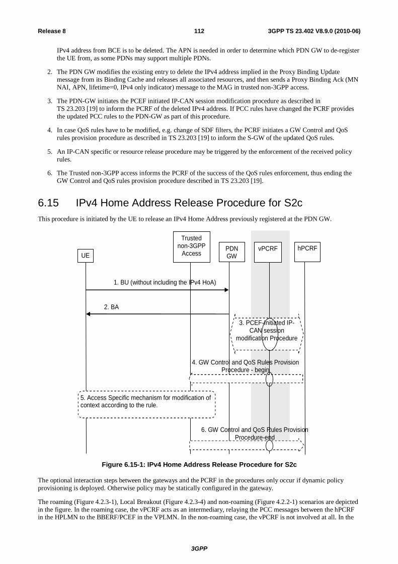
3GPP
3GPP TS 23.402 V8.9.0 (2010-06) 112Release 8
IPv4 address from BCE is to be deleted. The APN is needed in order to determine which PDN GW to de-register the UE from, as some PDNs may support multiple PDNs.
2. The PDN GW modifies the existing entry to delete the IPv4 address implied in the Proxy Binding Update message from its Binding Cache and releases all associated resources, and then sends a Proxy Binding Ack (MN NAI, APN, lifetime=0, IPv4 only indicator) message to the MAG in trusted non-3GPP access.
3. The PDN-GW initiates the PCEF initiated IP-CAN session modification procedure as described in TS 23.203 [19] to inform the PCRF of the deleted IPv4 address. If PCC rules have changed the PCRF provides the updated PCC rules to the PDN-GW as part of this procedure.
4. In case QoS rules have to be modified, e.g. change of SDF filters, the PCRF initiates a GW Control and QoS rules provision procedure as described in TS 23.203 [19] to inform the S-GW of the updated QoS rules.
5. An IP-CAN specific or resource release procedure may be triggered by the enforcement of the received policy rules.
6. The Trusted non-3GPP access informs the PCRF of the success of the QoS rules enforcement, thus ending the GW Control and QoS rules provision procedure described in TS 23.203 [19].
6.15 IPv4 Home Address Release Procedure for S2c This procedure is initiated by the UE to release an IPv4 Home Address previously registered at the PDN GW.
UE
1. BU (without including the IPv4 HoA)
PDN GW
Trusted non-3GPP
Access vPCRF hPCRF
3. PCEF-Initiated IP-CAN session
modification Procedure
5. Access Specific mechanism for modification of context according to the rule.
6. GW Control and QoS Rules Provision Procedure-end
4. GW Control and QoS Rules Provision Procedure - begin
2. BA
Figure 6.15-1: IPv4 Home Address Release Procedure for S2c
The optional interaction steps between the gateways and the PCRF in the procedures only occur if dynamic policy provisioning is deployed. Otherwise policy may be statically configured in the gateway.
The roaming (Figure 4.2.3-1), Local Breakout (Figure 4.2.3-4) and non-roaming (Figure 4.2.2-1) scenarios are depicted in the figure. In the roaming case, the vPCRF acts as an intermediary, relaying the PCC messages between the hPCRF in the HPLMN to the BBERF/PCEF in the VPLMN. In the non-roaming case, the vPCRF is not involved at all. In the

3GPP
3GPP TS 23.402 V8.9.0 (2010-06) 113Release 8
Roaming and LBO cases, the 3GPP AAA Proxy serves as an intermediary between the Trusted Non-3GPP IP Access and the 3GPP AAA Server in the HPLMN.
1. If the UE has previously registered IPv4 home address and wants to release it, the UE sends a Binding Update (IPv6 HoA, lifetime) message to the PDN GW without including the IPv4 HoA, indicating de-registration for the IPv4 Home Address only.
2. The PDN GW modifies the existing entry to delete the IPv4 home address implied in the Binding Update message from its Binding Cache and releases all associated resources, and then sends a Binding Ack message to the UE.
3. The PDN-GW initiates the PCEF initiated IP-CAN session modification procedure as described in TS 23.203 [19] to inform the PCRF of the deleted IPv4 address. If PCC rules have changed the PCRF provides the updated PCC rules to the PDN-GW as part of this procedure.
4. In case QoS rules have to be modified, e.g. change of SDF filters, the PCRF initiates a GW Control and QoS rules provision procedure as described in TS 23.203 [19] to inform the S-GW of the updated QoS rules.
5. An IP CAN specific or resource release procedure may be triggered by the enforcement of the received policy rules.
6. The Trusted non-3GPP access informs the PCRF of the success of the QoS rules enforcement, thus ending the GW Control and QoS rules provision procedure described in TS 23.203 [19].
7 Functional Description and Procedures for Un-trusted Non-3GPP IP Accesses
7.1 Control and User Plane Protocol Stacks
7.1.1 Protocol Options for S2b The following protocol shall be supported on S2b:
- PMIPv6
The figure below illustrates the control plane for Mobility Management (MM) and the user plane.

3GPP
3GPP TS 23.402 V8.9.0 (2010-06) 114Release 8
S2b ePDG MAG
Gateway LMA
IPv4/IPv6
L2/L1
PMIPv6
IPv4/IPv6
L2/L1
PMIPv6
L2/L1
IPv4/IPv6
L2/L1 L2/L1
IPv4/IPv6
L2/L1
Tunnelling Layer
IPv4/IPv6
IPv4/IPv6
S2b
ePDG MAG
Gateway LMA
UE
Control Plane User Plane
Tunnelling Layer
IPv4/IPv6
IPv4/IPv6
IPSEC IPSEC
UE
L2/L1 L2/L1
IPv4/IPv6
IKEv2
IPv4/IPv6
IKEv2
Legend: - According to terms defined in PMIPv6 specification, RFC 5213 [8], the functional entities terminating both
the control and user planes are denoted MAG in the non-3GPP IP access and LMA in the Gateway. LMA includes also the function of a Home Agent.
- The MM control plane stack is PMIPv6 (draft-ietf-netlmm-proxymip6 [8]) over IPv6/IPv4. - The user plane carries remote IPv4/v6 packets over either an IPv4 or an IPv6 transport network. Between
the UE and the ePDG, packets are encapsulated using IPSEC RFC 3948 [48]. - The tunnelling layer implements GRE encapsulation applicable for PMIPv6 [36].
Figure 7.1.1-1: Protocols for MM control and user planes of S2b for the PMIPv6 option
7.1.2 Protocol Options for S2c over Un-trusted Non-3GPP IP Accesses The following protocols shall be supported for S2c over un-trusted non-3GPP IP accesses:
- DSMIPv6, with IPsec and IKEv2 used to secure mobility signalling, as specified in RFC 4877 [22].
The figure below illustrates the control plane for Mobility Management (MM) and the user plane.
S2c
ePDG Gateway HA
UE
L2/L1
Tunnelling Layer
IPv4/IPv6
L2/L1 L2/L1
S2c
ePDG Gateway HA
UE
Control Plane User Plane
IPv4/IPv6
L2/L1
DSMIPv6
L2/L1
DSMIPv6
IPv4/IPv6
L2/L1 L2/L1 L2/L1
Tunnelling Layer
IPv4/IPv6
IPv4/IPv6 IPv4/IPv6 IPv4/IPv6 IPv4/IPv6
IPSEC IPSEC IPv4/IPv6 IPv4/IPv6
IPSEC IPSEC
Legend: - According to terms defined in DSMIPv6 [10], the functional entities terminating both the control and user
planes are denoted MN (Mobile Node) in the UE, and HA (Home Agent) in the Gateway. - The MM control plane stack is DSMIPv6 [10] over IPv6/IPv4. - The user plane carries remote IPv4/v6 packets over either an IPv4 or an IPv6 transport network. Between
the UE and the ePDG, packets are encapsulated using IPSEC RFC 3948 [48]. - The tunnelling layer implements IP encapsulation applicable for MIPv6 as defined in DSMIPv6 [10]. In
some cases the tunnelling layer may be transparent.
Figure 6.1.2-1: Protocols for MM control and user planes of S2c for the DSMIPv6 option

3GPP
3GPP TS 23.402 V8.9.0 (2010-06) 115Release 8
7.2 Initial Attach on S2b with PMIPv6
7.2.1 Initial Attach with PMIPv6 on S2b This clause is related to the case when the UE powers-on in an untrusted non-3GPP IP access network via S2b interface.
In the non-roaming case, PMIPv6 specification, RFC 5213 [8], is used to setup a PMIPv6 tunnel between the ePDG and the PDN GW. It is assumed that MAG is collocated with ePDG. The IPsec tunnel between the UE and the ePDG provides a virtual point-to-point link between the UE and the MAG functionality on the ePDG.
3. Proxy Binding Update
6. Proxy Binding Ack
5. Update PDN GW Address
2. IKEv2 Authentication and Tunnel Setup
8.IKEv2 (IP Address Configuration)
9. IPSec and PMIPv6 Tunnels
Roaming Scenarios
UE PDN GW vPCRF
AAA Proxy
HSS/ AAA hPCRF ePDG
PMIP Tunnel
7. IPSec Tunnel Setup Completion
IPSec
4. IP-CAN Session Establishment Procedure
2. Authentication & Authorization
Non-3GPP IP Access
1. Authentication & Authorization 1 Authentication and & authorisation
Figure 7.2.1-1: Initial attachment when Network-based MM mechanism are used over S2b for roaming, non-roaming and LBO
NOTE 1: Before the UE initiates the setup of an IPsec tunnel with the ePDG it configures an IP address from an untrusted non-3GPP IP access network. This address is used for sending all IKEv2 [9] messages and as the source address on the outer header of the IPsec tunnel.
The home routed roaming (Figure 4.2.3-1), LBO (Figure 4.2.3-4) and non-roaming (Figure 4.2.2-1) scenarios are depicted in the figure.
- In the LBO case, the 3GPP AAA Proxy acts as an intermediary, forwarding messages from the 3GPP AAA Server in the HPLMN to the PDN GW in the VPLMN and visa versa. Messages between the PDN GW in the VPLMN and the hPCRF in the HPLMN are forwarded by the vPCRF in the VPLMN.
- In the home routed roaming and non-roaming case, the vPCRF and the 3GPP AAA Proxy are not involved.
If dynamic policy provisioning is not deployed, the optional step 3 does not occur. Instead, the PDN GW may employ static configured policies.
The UE may be authenticated and authorised to access the Untrusted Non-3GPP Access network with an access network specific procedure. These procedures are outside the scope of 3GPP.
1) The Access authentication procedure between UE and the 3GPP EPC may be performed as defined by TS 33.402 [45]. In the roaming case signalling may be routed via a 3GPP AAA Proxy in the VPLMN, as specified in TS 23.234 [5]. As part of the AAA exchange for network access authentication, the AAA/HSS and/or the 3GPP AAA Proxy may return to the Non-3GPP IP Access a set of home/visited operator's policies to be enforced on the usage of local IP address, or IPv6 prefix, allocated by the access system upon successful authentication. Subscription data is provided to the Non-3GPP IP Access by the HSS/AAA in this step.
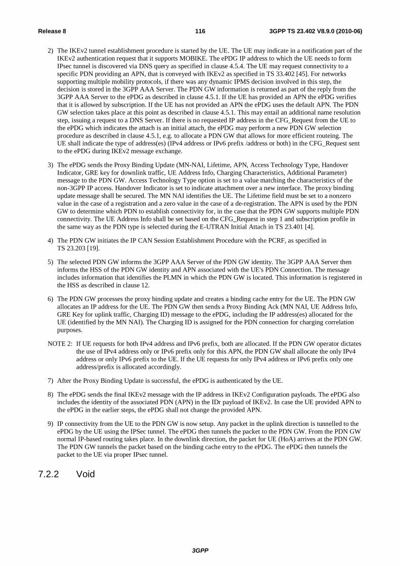
3GPP
3GPP TS 23.402 V8.9.0 (2010-06) 116Release 8
2) The IKEv2 tunnel establishment procedure is started by the UE. The UE may indicate in a notification part of the IKEv2 authentication request that it supports MOBIKE. The ePDG IP address to which the UE needs to form IPsec tunnel is discovered via DNS query as specified in clause 4.5.4. The UE may request connectivity to a specific PDN providing an APN, that is conveyed with IKEv2 as specified in TS 33.402 [45]. For networks supporting multiple mobility protocols, if there was any dynamic IPMS decision involved in this step, the decision is stored in the 3GPP AAA Server. The PDN GW information is returned as part of the reply from the 3GPP AAA Server to the ePDG as described in clause 4.5.1. If the UE has provided an APN the ePDG verifies that it is allowed by subscription. If the UE has not provided an APN the ePDG uses the default APN. The PDN GW selection takes place at this point as described in clause 4.5.1. This may entail an additional name resolution step, issuing a request to a DNS Server. If there is no requested IP address in the CFG_Request from the UE to the ePDG which indicates the attach is an initial attach, the ePDG may perform a new PDN GW selection procedure as described in clause 4.5.1, e.g. to allocate a PDN GW that allows for more efficient routeing. The UE shall indicate the type of address(es) (IPv4 address or IPv6 prefix /address or both) in the CFG_Request sent to the ePDG during IKEv2 message exchange.
3) The ePDG sends the Proxy Binding Update (MN-NAI, Lifetime, APN, Access Technology Type, Handover Indicator, GRE key for downlink traffic, UE Address Info, Charging Characteristics, Additional Parameter) message to the PDN GW. Access Technology Type option is set to a value matching the characteristics of the non-3GPP IP access. Handover Indicator is set to indicate attachment over a new interface. The proxy binding update message shall be secured. The MN NAI identifies the UE. The Lifetime field must be set to a nonzero value in the case of a registration and a zero value in the case of a de-registration. The APN is used by the PDN GW to determine which PDN to establish connectivity for, in the case that the PDN GW supports multiple PDN connectivity. The UE Address Info shall be set based on the CFG_Request in step 1 and subscription profile in the same way as the PDN type is selected during the E-UTRAN Initial Attach in TS 23.401 [4].
4) The PDN GW initiates the IP CAN Session Establishment Procedure with the PCRF, as specified in TS 23.203 [19].
5) The selected PDN GW informs the 3GPP AAA Server of the PDN GW identity. The 3GPP AAA Server then informs the HSS of the PDN GW identity and APN associated with the UE's PDN Connection. The message includes information that identifies the PLMN in which the PDN GW is located. This information is registered in the HSS as described in clause 12.
6) The PDN GW processes the proxy binding update and creates a binding cache entry for the UE. The PDN GW allocates an IP address for the UE. The PDN GW then sends a Proxy Binding Ack (MN NAI, UE Address Info, GRE Key for uplink traffic, Charging ID) message to the ePDG, including the IP address(es) allocated for the UE (identified by the MN NAI). The Charging ID is assigned for the PDN connection for charging correlation purposes.
NOTE 2: If UE requests for both IPv4 address and IPv6 prefix, both are allocated. If the PDN GW operator dictates the use of IPv4 address only or IPv6 prefix only for this APN, the PDN GW shall allocate the only IPv4 address or only IPv6 prefix to the UE. If the UE requests for only IPv4 address or IPv6 prefix only one address/prefix is allocated accordingly.
7) After the Proxy Binding Update is successful, the ePDG is authenticated by the UE.
8) The ePDG sends the final IKEv2 message with the IP address in IKEv2 Configuration payloads. The ePDG also includes the identity of the associated PDN (APN) in the IDr payload of IKEv2. In case the UE provided APN to the ePDG in the earlier steps, the ePDG shall not change the provided APN.
9) IP connectivity from the UE to the PDN GW is now setup. Any packet in the uplink direction is tunnelled to the ePDG by the UE using the IPSec tunnel. The ePDG then tunnels the packet to the PDN GW. From the PDN GW normal IP-based routing takes place. In the downlink direction, the packet for UE (HoA) arrives at the PDN GW. The PDN GW tunnels the packet based on the binding cache entry to the ePDG. The ePDG then tunnels the packet to the UE via proper IPsec tunnel.
7.2.2 Void

3GPP
3GPP TS 23.402 V8.9.0 (2010-06) 117Release 8
7.2.3 Initial Attach Procedure with PMIPv6 on S2b and Chained S2b and PMIP-based S8
This procedure is described in clause 6.2.4.
7.3 Initial Attach Procedure for S2c in Untrusted Non-3GPP IP Access
This clause is related to the case when the UE powers-on in an untrusted network and host-based mobility management mechanism is used to establish IP connectivity and to perform inter-access Handover. Dual Stack MIPv6 [10] is used for supporting mobility over S2c interface.
Roaming Scenarios
UE ePDG PDN GW HSS/ AAA
2. IKEv2 authentication and tunnel Setup
2. Authentication and Authorization
6. Binding Update
5. MIPv6 Security Association Setup and Home Address Configuration
3. IKEv2 (IP Address)
9 IPSec Tunnel
4. IPSec Tunnel
8. Binding Ack
10. DSMIPv6 Tunnel
7. IP-CAN Session Establishment Procedure
vPCRF 3GPP AAA
Proxy hPCRF
5. Authentication and Authorization
Non-3GPP IP Access
1. Authentication and Authorization 1.Access Authentication
Figure 7.3-1: Initial attachment from Untrusted Non-3GPP IP Access with DSMIPv6
The non-roaming (Figure 4.2.2-2), Roaming (Figure 4.2.3-3) and LBO (Figure 4.2.3-5) are all covered in this procedure. In the Roaming and LBO case, the ePDG communicates with the 3GPP AAA Server by way of the 3GPP AAA Proxy, functioning as a relay for AAA messages. In the LBO case, the PDN GW in the VPLMN interacts with the PCRF by means of the vPCRF. In the non-roaming case, the 3GPP AAA Proxy and vPCRF are not involved.
If dynamic policy provisioning is not deployed, the optional step 6 does not occur. Instead, the PDN GW may employ static configured policies.
1) The Access authentication procedure between UE and the 3GPP EPC may be performed as defined by TS 33.402 [45]. As part of the AAA exchange for network access authentication, the AAA/HSS and/or the 3GPP AAA Proxy may return to the Non-3GPP IP Access a set of home/visited operator's policies to be enforced on the usage of local IP address, or IPv6 prefix, allocated by the access system upon successful authentication. Subscription data is provided to the Non-3GPP IP Access by the HSS/AAA in this step. After the authentication, UE is configured with Local IP Address from the access network domain. This address is used for sending all IKEv2 [9] messages and as the source address on the outer header of the IPsec tunnel between the UE and the ePDG.

3GPP
3GPP TS 23.402 V8.9.0 (2010-06) 118Release 8
2) The IKEv2 tunnel establishment procedure is started by the UE. The UE may indicate in a notification part of the IKEv2 authentication request that it supports MOBIKE. The ePDG IP address to which the UE needs to form IPsec tunnel is discovered via DNS query as specified in clause 4.5.4. The procedure is as described in TS 33.234 [7].
3) The ePDG sends the final IKEv2 message with the assigned IP address in IKEv2 Configuration payloads.
4) IPsec Tunnel between the UE and ePDG is now setup.
5) A security association is established between UE and PDN GW to secure the DS-MIPv6 messages between UE and PDN GW. This step is performed as specified in step 4 of clause 6.3. During this step an IPv6 home network prefix is assigned by the PDN GW to the UE as defined in RFC 5026 [40]. After the IPv6 home network prefix is assigned, UE constructs a home address from it via auto-configuration.
6) The UE sends the Binding Update (IP Addresses (HoA, CoA)) message to the PDN GW. The Binding Update is as specified in RFC 5555 [10]. The UE may request an IPv4 Home Address in this step. The UE shall inform the PDN GW that the whole home prefix shall be moved.
7) The PDN GW executes a IP-CAN Session Establishment Procedure with the PCRF as specified in TS 23.203 [19]. The message from the PDG GW includes at least the HoA and the CoA. The message may also include a permanent UE identity and an APN string.
The PCRF decides on the PCC rules and Event Triggers and provisions them to the PDN GW. The PDN GW installs the received PCC rules.
8) The PDN GW processes the binding update and creates a binding cache entry for the UE. The PDN GW allocates an IPv4 home address for the UE if requested by the UE in step 5 and allowed by the subscription profile received as it is specified in the E-UTRAN attach procedure in TS 23.401 [4]. The PDN GW then sends a Binding Ack to the UE, including the IPv4 home address allocated for the UE.
9) The IP Connectivity is now setup.
7.4 Detach and PDN Disconnection for S2b
7.4.1 UE/ePDG-initiated Detach Procedure and UE-Requested PDN Disconnection with PMIPv6
7.4.1.1 Non-Roaming, Home Routed Roaming and Local Breakout Case
The procedure in this clause applies to Detach Procedures, initiated by UE or ePDG initiated detach procedure, and to the UE-requested PDN disconnection procedure.
The UE can initiate the Detach procedure, e.g. when the UE is power off. The ePDG may initiate the Detach procedure due to administration reason or the IKEv2 tunnel releasing.
For multiple PDN connectivity, this detach procedure shall be repeated for each PDN connected.

3GPP
3GPP TS 23.402 V8.9.0 (2010-06) 119Release 8
Roaming Scenarios
UE AAA Proxy vPCRF
PDN GW
HSS/ AAA hPCRF
2. Proxy Binding Update (lifetime=0)
ePDG
5. Proxy Binding Ack
3. Update PDN GW Address
6. Non-3GPP specific resource release procedure
1. IKEv2 tunnel release trigger
4. PCEF-Initiated IP-CAN Session Termination Procedure
Figure 7.4.1-1: UE/ePDG-initiated detach procedure with PMIPv6
The home routed roaming (Figure 4.2.3-1), LBO (Figure 4.2.3-4) and non-roaming (Figure 4.2.2-1) scenarios are depicted in the figure. In the LBO case, the 3GPP AAA Proxy acts as an intermediary, forwarding messages from the 3GPP AAA Server in the HPLMN to the PDN GW in the VPLMN and visa versa. Messages between the PDN GW in the VPLMN and the hPCRF in the HPLMN are forwarded by the vPCRF in the VPLMN. In the non-roaming case, the vPCRF and the 3GPP AAA Proxy are not involved.
If dynamic policy provisioning is not deployed, the optional steps 4 and 5 do not occur. Instead, the PDN GW may employ static configured policies.
1) IKEv2 tunnel release triggers PMIP tunnel release.
2) The MAG in the ePDG sends a Proxy Binding Update (MN NAI, APN, lifetime=0) message to the PDN GW. The MN NAI identifies the UE. The APN disambiguates the IP CAN session in the case where the same PDN GW is used for multiple PDN access. The lifetime value set to zero, indicates this is a PMIP de-registration.
3) The PDN GW informs the AAA Server/HSS to remove the PDN GW identity information and APN associated with the UE's PDN Connection. This information is registered in the HSS as described in clause 12.
4) The PDN GW deletes the IP CAN session associated with the UE and executes a PCEF-Initiated IP-CAN Session Termination Procedure with the PCRF as specified in TS 23.203 [19].
5) The PDN GW deletes all existing entries for the indicated HoA from its Binding Cache and sends a Proxy Binding Ack (MN NAI, lifetime=0) message to the MAG in the ePDG. The PDN GW sends a Proxy Binding Ack message to the ePDG. The MN NAI value and the lifetime=0 values indicate that the UE has been successfully deregistered.
6) Non-3GPP specific resource release procedure is executed.
7.4.1.2 Chained PMIP-based S8-S2b Roaming Case
This procedure is described in clause 6.4.1.2.

3GPP
3GPP TS 23.402 V8.9.0 (2010-06) 120Release 8
7.4.2 HSS/AAA-initiated Detach Procedure with PMIP
7.4.2.1 Non-Roaming, Home Routed Roaming and Local Breakout Case
HSS/AAA-initiated detach procedure with PMIPv6 for non-roaming case is illustrated in Figure 7.4.2-1. The HSS can initiate the procedure e.g. when the user's subscription is removed. The 3GPP AAA Server can initiate the procedure, e.g. instruction from O&M, timer for re-authentication/re-authorization expired.
Roaming Scenarios
UE AAA Proxy vPCRF
PDN GW
HSS/ AAA hPCRF ePDG
1. Detach Indication
3. Detach Ack
2. The procedures as TS 23.402, Figure 7.4.1-1, after Step 1
Figure 7.4.2-1: HSS/AAA-initiated detach procedure with PMIPv6
NOTE 1: AAA proxy and vPCRF are only used in the case of home routed roaming (Figure 4.2.3-1) and local breakout (Figure 4.2.3-4).
1) The HSS/AAA sends a detach indication message to the ePDG to detach a specific UE.
2) This include the procedure after step1 as Figure 7.4.1-1.
For multiple PDN connectivity, this step shall be repeated for each PDN connected.
3) The ePDG sends a Detach Ack message to the HSS.
NOTE 2: The HSS/AAA may also send a detach indication message to the PDN GW. The PDN GW does not remove the PMIP tunnels on S2b, since the ePDG is responsible for removing the PMIP tunnels on S2b. The PDN GW acknowledges the receipt of the detach indication message to the HSS/AAA.
7.4.2.2 Chained PMIP-based S8-S2b Roaming Case
This procedure is described in clause 6.4.2.2.
7.5 Detach and PDN Disconnection for S2c in Un-trusted Non-3GPP IP Access
7.5.1 General This clause is related to the cases where at least one DSMIPv6 PDN disconnection procedure is performed. In case of detach the DSMIPv6 PDN disconnection is executed for all the existing PDNs connections, while in the case of disconnecting a single PDN connection the DSMIPv6 PDN disconnection is executed only for the individual PDN connection.
The DSMIPv6 PDN disconnection procedure is on a per PDN basis and allows:
- the UE to inform the network that it requests to release a S2c based PDN connection; and
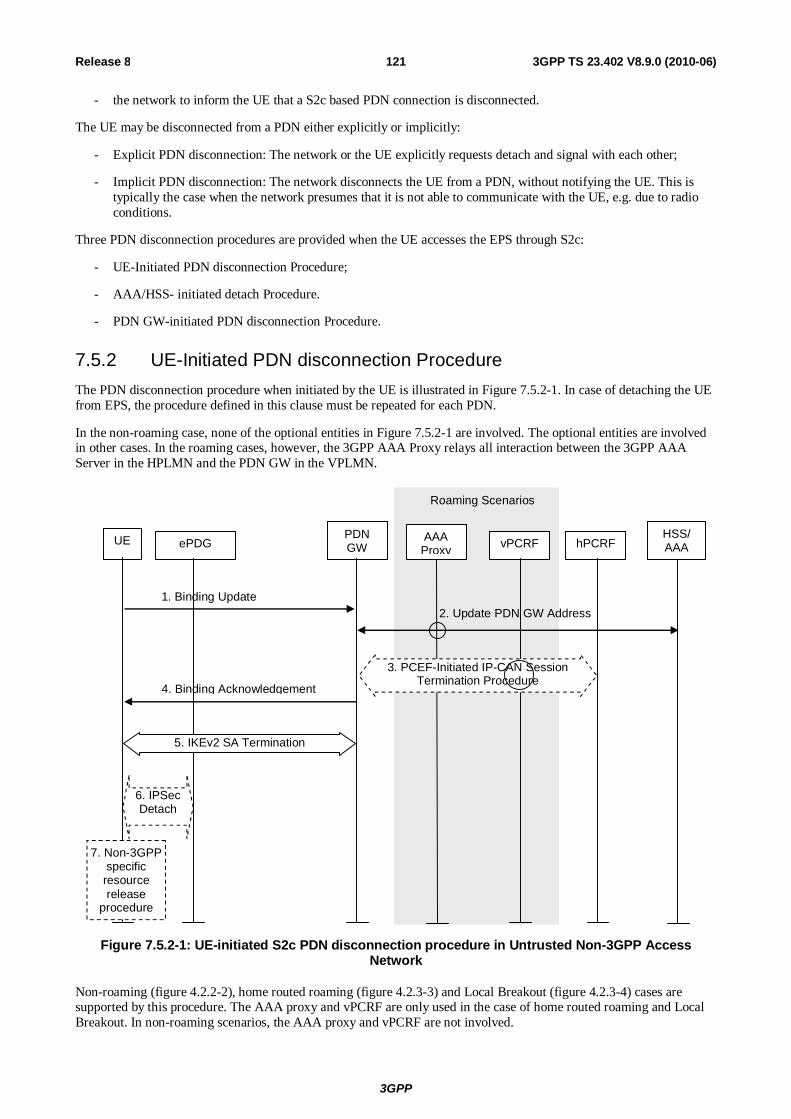
3GPP
3GPP TS 23.402 V8.9.0 (2010-06) 121Release 8
- the network to inform the UE that a S2c based PDN connection is disconnected.
The UE may be disconnected from a PDN either explicitly or implicitly:
- Explicit PDN disconnection: The network or the UE explicitly requests detach and signal with each other;
- Implicit PDN disconnection: The network disconnects the UE from a PDN, without notifying the UE. This is typically the case when the network presumes that it is not able to communicate with the UE, e.g. due to radio conditions.
Three PDN disconnection procedures are provided when the UE accesses the EPS through S2c:
- UE-Initiated PDN disconnection Procedure;
- AAA/HSS- initiated detach Procedure.
- PDN GW-initiated PDN disconnection Procedure.
7.5.2 UE-Initiated PDN disconnection Procedure The PDN disconnection procedure when initiated by the UE is illustrated in Figure 7.5.2-1. In case of detaching the UE from EPS, the procedure defined in this clause must be repeated for each PDN.
In the non-roaming case, none of the optional entities in Figure 7.5.2-1 are involved. The optional entities are involved in other cases. In the roaming cases, however, the 3GPP AAA Proxy relays all interaction between the 3GPP AAA Server in the HPLMN and the PDN GW in the VPLMN.
Roaming Scenarios
UE AAA Proxy vPCRF
PDN GW
HSS/ AAA hPCRF
1. Binding Update
ePDG
4. Binding Acknowledgement
2. Update PDN GW Address
3. PCEF-Initiated IP-CAN Session Termination Procedure
5. IKEv2 SA Termination
6. IPSec Detach
7. Non-3GPP specific resource release
procedure
Figure 7.5.2-1: UE-initiated S2c PDN disconnection procedure in Untrusted Non-3GPP Access Network
Non-roaming (figure 4.2.2-2), home routed roaming (figure 4.2.3-3) and Local Breakout (figure 4.2.3-4) cases are supported by this procedure. The AAA proxy and vPCRF are only used in the case of home routed roaming and Local Breakout. In non-roaming scenarios, the AAA proxy and vPCRF are not involved.
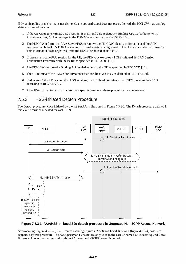
3GPP
3GPP TS 23.402 V8.9.0 (2010-06) 122Release 8
If dynamic policy provisioning is not deployed, the optional step 3 does not occur. Instead, the PDN GW may employ static configured policies.
1. If the UE wants to terminate a S2c session, it shall send a de-registration Binding Update (Lifetime=0, IP Addresses (HoA, CoA)) message to the PDN GW as specified in RFC 5555 [10].
2. The PDN GW informs the AAA Server/HSS to remove the PDN GW identity information and the APN associated with the UE's PDN Connection. This information is registered in the HSS as described in clause 12. This information is de-registered from the HSS as described in clause 12.
3. If there is an active PCC session for the UE, the PDN GW executes a PCEF-Initiated IP-CAN Session Termination Procedure with the PCRF as specified in TS 23.203 [19].
4. The PDN GW shall send a Binding Acknowledgement to the UE as specified in RFC 5555 [10].
5. The UE terminates the IKEv2 security association for the given PDN as defined in RFC 4306 [9].
6. If after step 5 the UE has no other PDN sessions, the UE should terminate the IPSEC tunnel to the ePDG according to RFC 4306 [9].
7. After IPsec tunnel termination, non-3GPP specific resource release procedure may be executed.
7.5.3 HSS-initiated Detach Procedure The Detach procedure when initiated by the HSS/AAA is illustrated in Figure 7.5.3-1. The Detach procedure defined in this clause must be repeated for each PDN.
Roaming Scenarios
UE AAA Proxy vPCRF
PDN GW
HSS/ AAA hPCRF
2. Detach Request
ePDG
3. Detach Ack
5. Session Termination Ack
4. PCEF-Initiated IP-CAN Session Termination Procedure
6. IKEv2 SA Termination
7. IPSec Detach
1. Session Termination
8. Non-3GPP specific resource release
procedure
Figure 7.5.3-1: AAA/HSS-initiated S2c detach procedure in Untrusted Non-3GPP Access Network
Non-roaming (Figure 4.2.2-2), home routed roaming (figure 4.2.3-3) and Local Breakout (figure 4.2.3-4) cases are supported by this procedure. The AAA proxy and vPCRF are only used in the case of home routed roaming and Local Breakout. In non-roaming scenarios, the AAA proxy and vPCRF are not involved.

3GPP
3GPP TS 23.402 V8.9.0 (2010-06) 123Release 8
If dynamic policy provisioning is not deployed, the optional step 4 does not occur. Instead, the PDN GW may employ static configured policies.
1. If the HSS/AAA wants to request the immediate termination of a S2c session for a given UE and a given PDN, it shall send a Session Termination message to the PDN GW.
2. The PDN GW sends a detach request message.
3. The UE shall acknowledge the detach request.
NOTE 1: How the detach request and acknowledge messages are implemented is a stage 3 issue.
4. If there is an active PCC session for the UE, the PDN GW executes a PCEF-Initiated IP-CAN Session Termination Procedure with the PCRF as specified in TS 23.203 [19].
5. The PDN GW shall acknowledge the termination of the S2c session to the 3GPP AAA Server/HSS. As part of this interaction with the 3GPP AAA Server/HSS, the PDN GW indicates that the AAA Server should remove the PDN GW address and APN associated with the UE's PDN Connection. As this is an HSS-initiated procedure, the mechanism described in clause 12.1.2 is not necessary.
6. The PDN GW or the UE terminates the IKEv2 security association for the given PDN as defined in RFC 4306 [9].
7. If after step 6 the UE has no other PDN sessions, the UE should terminate the IPSEC tunnel to the ePDG according to RFC 4306 [9].
8. After IPsec tunnel termination, non-3GPP specific resource release procedure may be executed.
NOTE 2: The HSS/AAA may also send a detach indication message to ePDG. The HSS/AAA should wait to receive acknowledgement(s) from PDN GW(s) before sending the detach indication to the ePDG. The ePDG releases the IPSEC tunnels to the UE and acknowledges the receipt of the detach indication message to the HSS/AAA.
7.5.4 PDN GW-initiated PDN Disconnection Procedure The PDN Disconnection procedure when initiated by the PDN GW is illustrated in Figure 7.5.4-1.

3GPP
3GPP TS 23.402 V8.9.0 (2010-06) 124Release 8
Roaming Scenarios
UE AAA Proxy vPCRF
PDN GW
HSS/ AAA hPCRF ePDG
1. Detach Request
2. Detach Ack
4. PCEF-Initiated IP-CAN Session Termination Procedure
5. IKEv2 SA Termination
3. Update PDN GW Address
6. Non-3GPP specific
resource release
procedure
Figure 7.5.4-1: PDN GW- initiated PDN Disconnection S2c procedure in Untrusted Non-3GPP Access Network
Non-roaming (Figure 4.2.2-1), home routed roaming (Figure 4.2.3-2) and Local Breakout (Figure 4.2.3-4) cases are supported by this procedure. The 3GPP AAA proxy and vPCRF are only used in the case of home routed roaming and Local Breakout. In non-roaming scenarios, the 3GPP AAA proxy and vPCRF are not involved.
If dynamic policy provisioning is not deployed, the optional step 3 does not occur. Instead, the PDN GW may employ static configured policies.
If the PDN GW-initiated PDN Disconnection Procedure is triggered by the UE binding lifetime expiration (Implicit PDN disconnection procedure), steps 1 and 2 may be omitted.
1. In the explicit detach procedure the PDN GW shall send a detach request message.
2. In the explicit detach procedure, the UE shall acknowledge the detach request.
NOTE: How the detach request and acknowledge messages are implemented is a stage 3 detail.
3. If this is the last PDN connection for the given APN, the PDN GW informs the 3GPPAAA Server/HSS to remove the PDN GW Identity information for the UE. If the PDN GW is in the VPLMN, signalling may be routed via a 3GPP AAA Proxy in the VPLMN.
4. If there is an active PCC session for the UE, the PDN GW shall execute a PCEF-Initiated IP CAN Session Termination Procedure with the PCRF as specified in TS 23.203 [19].
5. The PDN GW or the UE may terminate the IKEv2 security association for the given PDN as defined in RFC 4306 [9].
6. After IKEv2 SA termination, non-3GPP specific resource release procedure may be executed.

3GPP
3GPP TS 23.402 V8.9.0 (2010-06) 125Release 8
7.6 UE-initiated Connectivity to Additional PDN
7.6.1 UE-initiated Connectivity to Additional PDN with PMIPv6 on S2b NOTE: The PDN GW treats each MN-ID+APN as a separate binding and may allocate a new IP address/prefix
for each binding.
This clause is related to the case when the UE has an established PDN connection and wishes to establish one or more additional PDN connections. Since PMIPv6 is used to establish connectivity with the additional PDN, the UE establishes a separate SWu instance (i.e. a separate IPSec tunnel) for each additional PDN.
One PDN connection per APN is supported. If the UE requests a PDN connection for an APN for which the UE already has an active PDN connection, the ePDG shall reject the PDN connectivity request.
UE
PDN GW1
1. Initial S2b Attach as in Fig 7.2.1-1
2. S2b Attach to additional PDNs as in Fig 7.2.1-1
PDN GW2
ePDG
Figure 7.6.1-1: UE-initiated connectivity to additional PDN from Un-trusted Non-3GPP IP Access with PMIPv6
1) The UE has performed the Initial S2b Attach procedure as defined in clause 7.2.1, Figure 7.2.1-1 and has an established PDN connection.
2) The UE repeats the procedure of clause 7.2.1, Figure 7.2.1-1 for each additional PDN the UE wants to connect to, with the following exceptions:
a) The IKEv2 tunnel establishment procedure for each additional PDN connection is initiated with the ePDG that was selected in step 1;
b) The APN information corresponding to the requested PDN connection is conveyed with IKEv2 as specified in TS 33.402 [45];
c) For network supporting multiple mobility protocols, if there was any dynamic IPMS decision in step 1, the AAA/HSS enforces the same IPMS decision for each additional PDN connection.
7.6.2 UE-initiated Connectivity to Additional PDN from Un-trusted Non-3GPP IP Access with DSMIPv6 on S2c
This clause is related to the case when the UE powers-on in an untrusted network and host-based mobility management mechanism is used for obtaining connectivity. Dual Stack MIPv6 [10] is used for supporting mobility over S2c interface. This case covers the scenario when UE obtains connectivity with one or more additional PDNs at any time after initial attach Since host-based mobility mechanisms are used, the procedure is similar to the initial attach procedure.
NOTE: Based on the MN-ID and APN, the PDN GW may allocate a new IP address/prefix for a new binding.

3GPP
3GPP TS 23.402 V8.9.0 (2010-06) 126Release 8
UE PDN
GW1
1. Initial S2c PDN Attach as in Figure 7.3-1
2. S2c Attach to additional PDNs as in steps 4-8 of Figure 7.3-1
PDN GW2
ePDG
Figure 7.6.2-1: UE-initiated connectivity to additional PDN from Un-trusted Non-3GPP IP Access with DSMIPv6
When the initial attachment is performed, the UE performs procedures described in clause 7.3, Figure 7.3-1, to obtain connectivity with a PDN GW and a specific PDN. If at any time the UE wants to obtain connectivity with additional PDNs, since DSMIPv6 is used to obtain connectivity, the UE repeats only steps 4-8 of Figure 7.3-1.
1) The UE performs initial S2c PDN Attach procedure as defined in clause 7.3, Figure 7.3-1.
2) The UE repeats steps 4-8 of clause 7.3, Figure 7.3-1 for each additional PDN the UE wants to connect to. This step can be performed and repeated at any time after step 1 for one or multiple PDNs.
7.7 Void
7.8 S2c Bootstrapping via DSMIPv6 Home Link over an Un-Trusted Access
When the UE is connected on an un-trusted non-3GPP access considered to be DSMIPv6 home link for the UE based on clause 4.5.6, the UE may trigger the establishment of S2c IKEv2 SA, e.g. to optimize future handovers to other accesses using S2c. For each PDN connection, the S2c IKEv2 SA establishment has to be performed separately.
NOTE: An un-trusted non-3GPP access can be defined as DSMIPv6 Home Link in addition to the 3GPP access.
Once the UE is attached to the PDN over the un-trusted non-3GPP access, the procedure describing the bootstrapping is in clause 15.1.
7.9 PDN GW initiated Resource Allocation Deactivation The PDN GW initiated resource allocation deactivation procedure as defined in clause 6.12.1 should also apply to S2b PMIP reference point.
8 Handovers without Optimizations Between 3GPP Accesses and Non-3GPP IP Accesses
8.1 Common Aspects for Handover without Optimizations for Multiple PDNs
This clause describes the common aspects of handover for connectivity with multiple PDNs.

3GPP
3GPP TS 23.402 V8.9.0 (2010-06) 127Release 8
The support of multiple PDNs has the following impacts on the handover procedures for single PDN connectivity:
- Upon handover from 3GPP access to non-3GPP access, and from non-3GPP access to another non-3GPP access, using S2a or S2b, during the access authentication the HSS/AAA returns to the Trusted Non-3GPP Access or the ePDG the PDN GW identity and the associated APN for each PDN the UE is connected to. For non-3GPP accesses that support UE to establish connectivity to PDNs after attach, the UE performs an attach to the target non-3GPP access indicating that it is a handover, resulting in the UE being connected to one PDN, and the UE establishes connectivity with the remaining PDNs it was connected to in the 3GPP system before the handover using the UE-initiated Connectivity to Additional PDN procedure.
- If the UE hands over from 3GPP access with GTP-based S5/S8 to a non-3GPP access using PMIP-based S2a or S2b, and the UE has more than one PDN connection to a given APN in the source 3GPP access, only one PDN connection to the given APN will be established in the target non-3GPP access. In this case, the following applies:
a) If dynamic PCC is deployed and the PCRF receives a Gateway Control Session Establishment Request from the target BBERF indicating an IP-CAN type different from 3GPP access, the PCRF shall select one of the IP-CAN sessions for this APN and continue with the BBERF relocation procedure for that PDN connection.
b) When the PDN GW receives a PBU over PMIP-based S2a or S2b, the PDN GW shall select one of the PDN connections for this APN and continue with the handover procedure for that PDN connection. The PDN GW shall terminate the remaining PDN connections for that APN without removing the PDN GW information in HSS. If dynamic PCC is deployed, the PDN GW informs the PCRF about the deactivated PDN connections using the PCEF initiated IP-CAN session termination procedure as described in TS 23.203 [19].
c) Whenever the PDN GW receives a PBU containing an IPv6 prefix or an IPv4 address associated to one of the PDN connections and the IPv6 prefix or the IPv4 address is valid, the PDN GW shall use the IPv6 prefix or the IPv4 address to select the PDN connection out of the active PDN connections. In cases where the information is not included in the PBU, the PDN GW and PCRF shall select the latest PDN connection out of the active PDN connections for the given APN (i.e. the PDN connection that was activated last out of the active PDN connections for the given APN).
NOTE: The UE may disconnect from certain PDN connections while still in the 3GPP access to ensure that there is only one PDN connection per APN when handing over to non-3GPP access.
- Upon handover from non-3GPP access to 3GPP access, if the MME has changed since the last detach or if there is no valid Subscriber context for the UE in the MME, or if the ME identity has changed, during the access authentication the HSS returns the Subscriber Data to the MME, including the PDN GW identity and the associated APN for each PDN the UE is connected to before the handover. The UE performs an attach to the 3GPP access with and indication for "handover" and then establishes connectivity with the remainder of PDNs that it was connected with over the non-3GPP system before the handover, using UE requested PDN connectivity specified in TS 23.401 [4]. The UE provides an indication of "handover" by providing Request Type indicating "handover" in the PDN connectivity request message as specified in TS 23.401 [4].
- For connectivity based on S2c:
- Upon handover from 3GPP access to non-3GPP access, and from non-3GPP access to another non-3GPP access, the UE performs DSMIPv6 bootstrapping (if not yet performed) and binding procedures for each PDN connection.
- Upon handover from non-3GPP access, the UE de-registers the DSMIPv6 binding for each PDN connection.
3GPP
3GPP TS 23.402 V8.9.0 (2010-06) 128Release 8
8.2 Handovers between non-3GPP IP access with PMIPv6 on S2a/S2b and 3GPP Access
8.2.1 Handover from Trusted or Untrusted Non-3GPP IP Access with PMIPv6 on S2a/S2b to 3GPP Access
8.2.1.1 General Procedure for GTP based S5/S8 for E-UTRAN Access
The steps involved in the handover from a trusted or untrusted non-3GPP IP access to E-UTRAN connected to EPC are depicted below for both the non-roaming and roaming cases and when PMIPv6 is used on S2a or S2b or MIPv4 FACoA is used on S2a. It is assumed that while the UE is served by the trusted or untrusted non-3GPP IP access, a PMIPv6 tunnel or MIPv4 tunnel is established between the non-3GPP access network and the PDN GW in the EPC.
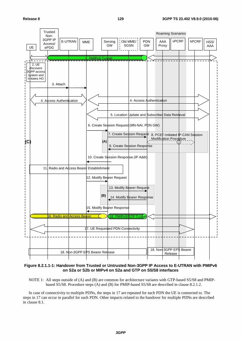
3GPP
3GPP TS 23.402 V8.9.0 (2010-06) 129Release 8
Old MME/ SGSN
PDN GW
hPCRF
UE
Trusted Non-
3GPP IP Access/ ePDG
E-UTRAN MME Serving GW
HSS/ AAA
1. PMIPv6 Tunnel
3. Attach
4. Access Authentication 4. Access Authentication
5. Location Update and Subscriber Data Retrieval
6. Create Session Request (MN-NAI, PDN GW)
7. Create Session Request
9. Create Session Response
13. Modify Bearer Request
14. Modify Bearer Response
10. Create Session Response (IP Addr)
11. Radio and Access Bearer Establishment
16. PMIPv6/GTP Tunnel 16. Radio and Access Bearer
2. UE discovers
3GPP access system and initiates HO
(A)
(B)
vPCRF AAA Proxy
18. Non-3GPP EPS Bearer Release 18. Non-3GPP EPS Bearer
Release
(C)
Roaming Scenarios
8. PCEF-Initiated IP-CAN Session Modification Procedure
12. Modify Bearer Request
15. Modify Bearer Response
17. UE Requested PDN Connectivity
Figure 8.2.1.1-1: Handover from Trusted or Untrusted Non-3GPP IP Access to E-UTRAN with PMIPv6 on S2a or S2b or MIPv4 on S2a and GTP on S5/S8 interfaces
NOTE 1: All steps outside of (A) and (B) are common for architecture variants with GTP-based S5/S8 and PMIP-based S5/S8. Procedure steps (A) and (B) for PMIP-based S5/S8 are described in clause 8.2.1.2.
In case of connectivity to multiple PDNs, the steps in 17 are repeated for each PDN the UE is connected to. The steps in 17 can occur in parallel for each PDN. Other impacts related to the handover for multiple PDNs are described in clause 8.1.

3GPP
3GPP TS 23.402 V8.9.0 (2010-06) 130Release 8
The optional interaction steps between the gateways and the PCRF in the procedures only occur if dynamic policy provisioning is deployed. Otherwise policy may be statically configured with the gateway.
Both the roaming (Figure 4.2.1-2) and non-roaming (Figure 4.2.1-1) scenarios are depicted in the figure. In the roaming case, the vPCRF acts as an intermediary, sending the QoS Policy Rules Provision from the hPCRF in the HPLMN to the Serving GW in the VPLMN. The vPCRF receives the Acknowledgment from the Serving GW and forwards it to the hPCRF. In the non-roaming case, the vPCRF is not involved at all.
The steps involved in the handover are discussed below.
1) The UE uses a trusted or untrusted non-3GPP access system and is being served by PDN GW (as PMIPv6 LMA or MIPv4 HA).
2) The UE discovers the E-UTRAN access and determines to transfer its current sessions (i.e. handover) from the currently used non-3GPP access system to E-UTRAN. The mechanisms that aid the UE to discover the 3GPP Access system, are specified in clause 4.8 (Network Discovery and Selection).
3) The UE sends an Attach Request to the MME with Request Type indicating "Handover" Attach. The message from the UE is routed by E-UTRAN to the MME as specified in TS 23.401 [4] (E-UTRAN). The UE should include any one of the APNs, corresponding to the PDN connections in the source non-3GPP access. The APN is provided as specified in TS 23.401 [4].
4) The MME may contact the HSS and authenticate the UE.
5) After successful authentication, the MME may perform location update procedure and subscriber data retrieval from the HSS as specified in TS 23.401 [4]. Since the Request Type is "Handover", the PDN GW identity conveyed to the MME will be stored in PDN subscription context. The MME receives information on the PDNs the UE is connected to over the non-3GPP access in the Subscriber Data obtained from the HSS.
6) The MME selects an APN, a serving GW and PDN GW as described in TS 23.401 [4]. The MME sends a Create Session Request (including IMSI, MME Context ID (SGSN equivalent is TBD), PDN-GW address, Handover Indication, APN) message to the selected Serving GW. Since the Request Type is "Handover", a Handover Indication information is included.
7) The Serving GW sends a Create Session Request (Handover Indication) message to the PDN-GW in the VPLMN or HPLMN as described in TS 23.401 [4]. Since the MME includes Handover Indication information in Create Session Request message, the Serving GW includes this information in Create Session Request message.
Since Handover Indication is included, the PDN GW should not switch the tunnel from non-3GPP IP access to 3GPP access system at this point.
8) Since Handover Indication is included, the PDN GW executes a PCEF-Initiated IP CAN Session Modification Procedure with the PCRF as specified in TS 23.203 [19] to obtain the rules required for the PDN GW in the VPLMN or HPLMN to function as the PCEF for all the active sessions the UE has established with the new IP-CAN type as a result of the handover procedure. If the UE had disconnected from the default PDN before handover then the PDN GW executes a PCEF initiated IP CAN Session Establishment procedures as described in TS 23.203 [19].
If the updated PCC rules require establishment of dedicated bearer for the UE, the establishment of those bearers take place before step 12. The establishment of dedicated bearers in combination with the default takes place as described in Annex F of TS 23.401 [4].
Since Handover Indication is included in step 7, the PDN GW stores the new PCC Rules for E-UTRAN access as well as the old PCC Rules for the Trusted or Untrusted Non-3GPP IP access and still applies the old PCC Rules for charging.
NOTE 3: PDN GW address and Serving GW address selection is as described in the clause "GW selection" in TS 23.401 [4].
9) The PDN GW responds with a Create Session Response message to the Serving GW as described in TS 23.401 [4].The Create Session Response contains the IP address or the prefix that was assigned to the UE while it was connected to the non-3GPP IP access.
10) The Serving GW returns a Create Session Response message to the MME as specified in TS 23.401 [4]. This message also includes the IP address of the UE. This message also serves as an indication to the MME that the
3GPP
3GPP TS 23.402 V8.9.0 (2010-06) 131Release 8
S5 bearer setup and update has been successful. At this step the PMIPv6 or GTP tunnel(s) over S5 are established.
11) Radio and Access bearers are established at this step in the 3GPP access as specified in TS 23.401 [4].
12) The MME sends a Modify Bearer Request (eNodeB address, eNodeB TEID, Handover Indication) message to the Serving GW.
13) Since the Handover Indication is included in step 12), the Serving GW sends a Modify Bearer Request message to the PDN GW to prompt the PDN GW to tunnel packets from non 3GPP IP access to 3GPP access system and immediately start routing packets to the Serving GW for the default and any dedicated EPS bearers established.
In this step, The PDN GW removes the old PCC Rules for the Trusted or Untrusted Non-3GPP IP access and applies the new Rules for E-UTRAN access for charging.
NOTE 4: Steps 13 and 14 are not performed if the PDNs are reconnected after handoff by the UE in step 17.
14) The PDN GW acknowledges by sending Modify Bearer Response to the Serving GW.
15)The Serving GW acknowledges by sending Modify Bearer Response (EPS Bearer Identity) message to the MME.
16) The UE sends and receives data at this point via the E-UTRAN system.
17) For connectivity to multiple PDNs, the UE establishes connectivity to each PDN, the UE was connected to before the handover, besides the PDN connection established in steps 3-15, by executing the UE requested PDN connectivity procedure specified in TS 23.401 [4].
18) The PDN GW shall initiate resource allocation deactivation procedure in the trusted/untrusted non-3GPP IP access as defined in clause 6.12 or clause 7.9.
8.2.1.2 Using PMIP-based S5/S8
When a Trusted or Untrusted Non-3GPP IP Access to 3GPP Access handover occurs, the following steps are performed instead of and in addition to the steps performed in the GTP-based S5/S8 case (see previous clause). In the case of PMIP-based S5/S8, a Create Session Request and Modify Bearer Request is not sent from the Serving GW to the PDN GW. Rather, the serving GW interacts with the hPCRF and PMIP messages are exchanged between the Serving GW and the PDN GW.

3GPP
3GPP TS 23.402 V8.9.0 (2010-06) 132Release 8
Old MME PDN GW HSS/ AAA UE
E-UTRAN MME Serving GW
hPCRF
B.1. Proxy Binding Update
B.3. Proxy Binding Ack
Trusted / Untrusted
Non-3GPP IP Access
vPCRF
Roaming Scenario
Procedure as per Figure 8.2.1.1-1 before Step (A)
Procedure as per Figure 8.2.1.1-1 between Step (A) and Step (B)
Procedure as per Figure 8.2.1.1-1 between Step (B) and step 17
A.1 Gateway Control Session Establishment Procedure
B.2. PCEF Initiated IP-CAN Session Modification Procedure
A.2. Proxy Binding Update
A.4. Proxy Binding Ack
Alt. A)
Alt. B)
18. UE Requested PDN Connectivity
19. Non-3GPP EPS Bearer Release 19. Non-3GPP EPS Bearer Release
A.3. PCEF Initiated IP-CAN Session Modification Procedure
Figure 8.2.1.2-1: Trusted/Untrusted Non-3GPP IP Access to E-UTRAN Handover over PMIP-based S2a and using PMIP-based S5/S8
This procedure supports the home routed (Figure 4.2.2.1), roaming (Figure 4.2.3-1) and Local breakout (Figure 4.2.3-4) case. The Serving GW establishes a Gateway Control Session with the PCRF in the HPLMN. In the case of the roaming or local breakout scenario, the Serving GW interacts with the hPCRF by way of the vPCRF. The signalling takes place through the vPCRF in the VPLMN. In the case of Local Breakout, the PDN GW in the VPLMN exchanges messages with the vPCRF. The vPCRF then exchanges messages with the hPCRF in the HPLMN.
The optional interaction steps between the gateways and the PCRF in Figure 8.2.1.2-1 only occur if dynamic policy provisioning is deployed. Otherwise policy may be statically configured with the gateway.
The steps shown in (Alt A) and (Alt B) are mutually exclusive in this procedure, i.e. either steps A.2-A.5 are executed or steps B.1-B.3. In order to execute the alternative (Alt B), the IP Address(es) of the UE needs to be available after step A.1. The IP Address(es) of the UE is received in step A.1, if dynamic policy provisioning is deployed.

3GPP
3GPP TS 23.402 V8.9.0 (2010-06) 133Release 8
In case the IP address(es) of the UE is available after step A1, (Alt B) provides lower jitter for dual radio handovers. In case the IP address(es) of the UE is not available after step A1, (Alt A) shall be used.
A.1) The Serving GW initiates a Gateway Control Session Establishment Procedure with the PCRF as specified in TS 23.203 [19] to obtain the rules required for the Serving GW to perform the bearer binding for all the active sessions the UE may establish as a result of the handover procedure.
If the updated QoS rules require establishment of dedicated bearer for the UE, the establishment of those bearers take place before step B1. The establishment of dedicated bearers in combination with the default takes place as described in Annex F of TS 23.401 [4].
A.2) The Serving GW sends a PMIPv6 Proxy Binding Update (MN NAI, Lifetime, Access Technology Type, Handover Indicator, IP Address Requested, APN, GRE Key for downlink traffic, Additional Parameters) message to the PDN GW. The MN NAI identifies the UE. The Lifetime field must be set to a non-zero value in the case of a registration. Access Technology Type is set to indicate 3GPP access to EPS. The Serving GW includes request for IPv4 Home Address and/or IPv6 Home Network Prefix as specified in step C.2 of clause 5.2. The APN may be necessary to differentiate the intended PDN from the other PDNs supported by the same PDN GW. The optional Additional Parameters may contain information, for example, protocol configuration options.
A.3) The PDN GW executes a PCEF-Initiated IP-CAN Session Modification Procedure with the PCRF as specified in TS 23.203 [19] to obtain the rules required for the PDN GW to function as the PCEF for all the active IP sessions the UE has established with new IP-CAN type.
A.4) The PDN GW responds with a Proxy Binding Ack (MN NAI, Lifetime, UE Address Info, GRE key for uplink traffic, Charging ID, Additional Parameters) message to the Serving GW. The MN NAI is identical to the MN NAI sent in the Proxy Binding Update. The Lifetime indicates the duration the binding will remain valid. The UE address info returns the IP Address assigned to the UE. IP address allocation by the PDN-GW is as specified in clause 4.7.1. If the PDN GW sends the DHCPv4 Address Allocation Procedure Indication in the Proxy Binding Acknowledgement message, the UE IPv4 address assigned by the PDN GW is not provided as part of the default bearer activation procedures to the UE. In this case, the Serving GW does not forward the IPv4 address assigned by the PDN GW to the MME, but sets the PDN Address to 0.0.0.0 in the message to the MME. The optional Additional Parameter information element may contain other information, including for example Protocol Configuration Options. The Serving GW acts as the MAG (in terms of PMIPv6). Since this step is triggered by the Proxy Binding Update message from the Serving GW in step A.2, it can occur after step A.2 and does not need to wait for step A.3.
NOTE 2: PDN GW address selection is as described in TS 23.401 [4].
Steps between A and B.1 are described in clause 8.2.1.1.
B.1-B.3) Corresponds to steps A.2 - A.4, respectively.
Steps between B.1 and 18 are described in clause 8.2.1.1.
18) For connectivity to multiple PDNs, the UE establishes connectivity to each PDN, the UE was connected to before the handover, besides the PDN connection established in the steps above, by executing the UE requested PDN connectivity procedure specified in clause 5.6.1.
19) The PDN GW shall initiate resource allocation deactivation procedure in the trusted/untrusted non-3GPP IP access as defined in clause 6.12 or clause 7.9.
8.2.1.3 General Procedure for GTP-based S5/S8 for UTRAN/GERAN
The steps involved in the handover from a trusted/untrusted non-3GPP IP access to UTRAN/GERAN connected to EPC are depicted below for both the non-roaming and roaming cases and when PMIPv6 is used on S2a or S2b. It is assumed that while the UE is served by the trusted/untrusted non-3GPP IP access, a PMIPv6 tunnel is established between the non-3GPP access network and the PDN GW in the EPC.
NOTE: This procedure is applicable to S4-SGSN only.
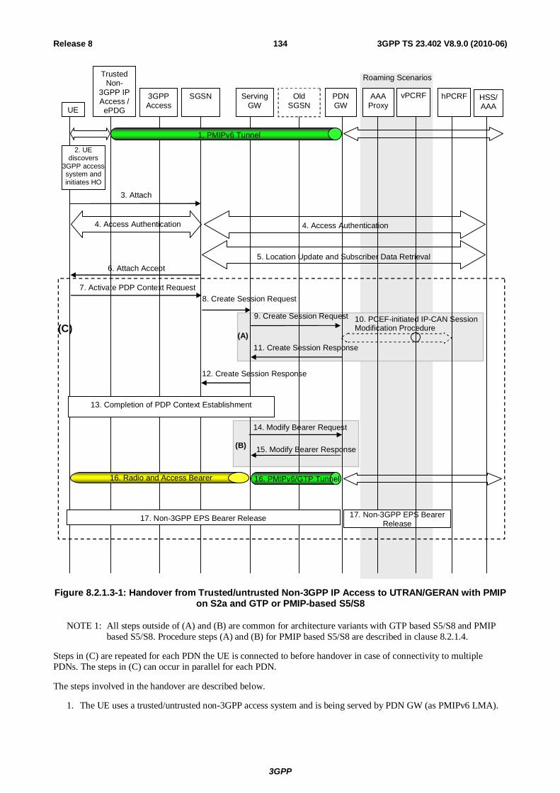
3GPP
3GPP TS 23.402 V8.9.0 (2010-06) 134Release 8
Old SGSN
PDN GW
hPCRF
UE
Trusted Non-
3GPP IP Access / ePDG
3GPP Access
SGSN Serving GW
HSS/ AAA
1. PMIPv6 Tunnel
3. Attach
4. Access Authentication 4. Access Authentication
5. Location Update and Subscriber Data Retrieval
8. Create Session Request
9. Create Session Request
11. Create Session Response
14. Modify Bearer Request
15. Modify Bearer Response
12. Create Session Response
13. Completion of PDP Context Establishment
16. PMIPv6/GTP Tunnel 16. Radio and Access Bearer
2. UE discovers
3GPP access system and initiates HO
(A)
(B)
vPCRF AAA Proxy
17. Non-3GPP EPS Bearer Release 17. Non-3GPP EPS Bearer Release
(C)
Roaming Scenarios
10. PCEF-initiated IP-CAN Session Modification Procedure
6. Attach Accept
7. Activate PDP Context Request
Figure 8.2.1.3-1: Handover from Trusted/untrusted Non-3GPP IP Access to UTRAN/GERAN with PMIP on S2a and GTP or PMIP-based S5/S8
NOTE 1: All steps outside of (A) and (B) are common for architecture variants with GTP based S5/S8 and PMIP based S5/S8. Procedure steps (A) and (B) for PMIP based S5/S8 are described in clause 8.2.1.4.
Steps in (C) are repeated for each PDN the UE is connected to before handover in case of connectivity to multiple PDNs. The steps in (C) can occur in parallel for each PDN.
The steps involved in the handover are described below.
1. The UE uses a trusted/untrusted non-3GPP access system and is being served by PDN GW (as PMIPv6 LMA).

3GPP
3GPP TS 23.402 V8.9.0 (2010-06) 135Release 8
2. The UE discovers the 3GPP Access system (UTRAN or GERAN) and determines to transfer its current sessions (i.e. handover) from the currently used non-3GPP access system to the discovered 3GPP Access system. The mechanisms that aid the UE to discover the 3GPP Access system, are specified in clause 4.8 (Network Discovery and Selection).
3. The UE sends an Attach Request to the SGSN. The message from the UE is routed by 3GPP Access to the SGSN as specified in clause 6.5 of TS 23.060 [21].
4. The SGSN may contact the HSS and authenticate the UE as described in TS 23.060 [21].
5. The SGSN may perform location update procedure and subscriber data retrieval from the HSS as specified in TS 23.060 [21]. PDN GW identity information is part of the subscriber data..
6. The SGSN sends the Attach Accept request to the UE to indicate the completion of the attach procedure as defined in TS 23.060 [21].
7. The UE initiate at this stage this establishment of the primary PDP context as defined in clause 9.2.2 of TS 23.060 [21].
8. The SGSN selects a Serving GW as described in TS 23.060 [21] and sends Create Session Request (Handover indication, and other parameters described in TS 23.060 [21]) message to the selected Serving GW.
9. The Serving GW sends a Create Session Request message to the PDN-GW as described in TS 23.060 [21]. The PDN GW should not switch the tunnel from non-3GPP IP access to 3GPP access system at this point.
10. The PDN GW executes a PCEF-Initiated IP CAN Session Modification Procedure with the PCRF as specified in TS 23.203 [19] to obtain the rules required for the PDN GW to function as the PCEF for all the active sessions the UE has established with the new IP-CAN type as a result of the handover procedure.
If the updated PCC rules require establishment of dedicated EPS bearers for the UE, the establishment of those bearers take place before step 12. The Dedicated bearer shall be mapped to Secondary PDP contexts by the Serving Gateway. The default and dedicated bearers are synchronised as described in Annex F of TS 23.401 [4].
Since the PDN GW does not switch the tunnel in step 9, it stores the new PCC Rules for UTRAN/GERAN access as well as the old PCC Rules for the Trusted or Untrusted Non-3GPP IP access and still applies the old PCC Rules for charging.
NOTE 2: PDN GW address and Serving GW address selection is as described in the clause "GW selection" in TS 23.401 [4].
11. The PDN GW responds with a Create Session Response message to the Serving GW as described in TS 23.060 [21].The Create Session Response contains the IP address or the prefix that was assigned to the UE while it was connected to the non-3GPP IP access.
12. The Serving GW returns a Create Session Response message to the SGSN as specified in TS 23.060 [21]. This message also includes the IP address of the UE. This message also serves as an indication to the SGSN that the S5 bearer setup and update has been successful.
13. The rest of the PDP context establishment as specified in TS 23.060 [21] is completed here.
14.The Serving GW sends a Modify Bearer Request message to the PDN GW in the VPLMN or the HPLMN including the Handover Indication flag that prompts the PDN GW to tunnel packets from non 3GPP IP access to 3GPP access system and immediately start routing packets to the Serving GW for the default and any dedicated EPS bearers established. In case of non-roaming or roaming with home routed traffic this message is sent to the PDN GW in the HPLMN. In case of local breakout traffic the message is sent to the PDN GW in the VPLMN.
In this step, The PDN GW removes the old PCC Rules for the Trusted or Untrusted Non-3GPP IP access and applies the new Rules for UTRAN/GERAN access for charging.
15. The PDN GW acknowledges by sending Modify Bearer Response to the Serving GW.
16. The UE sends and receives data at this point via the 3GPP access system.
17. The PDN GW shall initiate resource allocation deactivation procedure in the trusted/untrusted non-3GPP IP access as defined in clause 6.12 or clause 7.9.

3GPP
3GPP TS 23.402 V8.9.0 (2010-06) 136Release 8
8.2.1.4 Using PMIP-based S5/S8
When a Trusted/untrusted Non-3GPP IP Access to UTRAN/GERAN handover occurs, the following steps are performed instead of and in addition to the steps performed in the GTP based S5/S8 case (see previous clause). In the case of PMIP based S5/S8, a Create Session Request and Modify Bearer Request is not sent from the Serving GW to the PDN GW. Rather, the serving GW interacts with the hPCRF and PMIP messages are exchanged between the Serving GW and the PDN GW.
PDN GW HSS/ AAA UE
3GPP Access
SGSN Serving GW
hPCRF
B.1. Proxy Binding Update
B.3. Proxy Binding Ack
Trusted / Untrusted
Non-3GPP IP Access
vPCRF
Roaming Scenario
Procedure as per Figure 8.2.1.3-1 before Step 7
Procedure as per Figure 8.2.1.3-1 between Step (A) and Step (B)
Procedure as per Figure 8.2.1.3-1 after Step (B)
A.1 Gateway Control Session Establishment Procedure
B.2. PCEF Initiated IP-CAN Session Modification Procedure
Alt. A)
Alt. B)
A.2. Proxy Binding Update
A.4. Proxy Binding Ack
Procedure as per Figure 8.2.1.3-1 Steps 7-8
(C)
A.3. PCEF Initiated IP-CAN Session Modification Procedure
Figure 8.2.1.4-1: Trusted/untrusted Non-3GPP IP Access to GERAN/UTRAN over PMIP-based S2a and using PMIP-based S5/S8
Steps in (C) are repeated for each PDN the UE is connected to before handover in case of connectivity to multiple PDNs. The steps in (C) can occur in parallel for each PDN.
This procedure supports the home routed (Figure 4.2.2-1), roaming (Figure 4.2.3-1) and Local breakout (Figure 4.2.3-4) case. The Serving GW establishes a Gateway Control Session with the PCRF in the HPLMN. In the case of the roaming or local breakout scenario, the Serving GW interacts with the hPCRF by way of the vPCRF. The signalling takes place through the vPCRF in the VPLMN. In the case of Local Breakout, the PDN GW in the VPLMN exchanges messages with the vPCRF. The vPCRF then exchanges messages with the hPCRF in the HPLMN.
The optional interaction steps between the gateways and the PCRF in Figure 8.2.1.4-1 only occur if dynamic policy provisioning is deployed. Otherwise policy may be statically configured with the gateway.
3GPP
3GPP TS 23.402 V8.9.0 (2010-06) 137Release 8
The steps shown in (Alt A) and (Alt B) are mutually exclusive in this procedure, i.e. either steps A.2-A.5 are executed or steps B.1-B.3. In order to execute the alternative (Alt B), the IP Address(es) of the UE needs to be available after step A.1. The IP Address(es) of the UE is received in step A.1, if dynamic policy provisioning is deployed.
In case the IP address(es) of the UE is available after step A1, (Alt B) provides lower jitter for dual radio handovers. In case the IP address(es) of the UE is not available after step A1, (Alt A) shall be used.
A.1) The Serving GW initiates a Gateway Control Session Establishment Procedure with the PCRF as specified in TS 23.203 [19] to obtain the rules required for the Serving GW to perform the bearer binding for all the active sessions the UE may establish as a result of the handover procedure.
If the updated PCC rules require establishment of dedicated bearer for the UE, the establishment of those bearers take place before step B.1.
The description of steps A.1 to A.4 and B.1 to B.3 are the same as in clause 8.2.1.2.
8.2.2 3GPP Access to Trusted Non-3GPP IP Access Handover with PMIPv6 on S2a
The steps involved in the handover from 3GPP Access connected to the EPC to trusted non-3GPP IP access are depicted below for the case of non-roaming, roaming with home routed traffic, roaming with local breakout and roaming with anchoring in the Serving Gateway in the VPLMN. It is assumed that while the UE is served by the 3GPP Access, a PMIPv6 or GTP tunnel is established between the S-GW and the PDN GW in the evolved packet core.

3GPP
3GPP TS 23.402 V8.9.0 (2010-06) 138Release 8
Serving GW
PDN GW UE
Trusted Non-
3GPP IP Access
hPCRF
1. PMIPv6/ GTP tunnel
3. Access Authentication
3. Authentication and Authorization (PDN GW)
6. Proxy Binding Update
8. Proxy Binding Ack (IP Addr)
10. PMIPv6 tunnel
2. UE discovers Trusted Non-3GPP Access and initiates
HO
HSS/ AAA
vPCRF AAA Proxy
Roaming Scenarios
3GPP Access
MME/ SGSN
4. L3 Attach Trigger
9. L3 Attach Completion
12. 3GPP EPS Bearer Release 12. 3GPP EPS Bearer Release
5. Gateway Control Session Establishment Procedure
7. PCEF-Initiated IP-CAN Session Modification Procedure
11. UE-initiated Connectivity to Additional PDN
Figure 8.2.2-1: Handover from 3GPP Access to Trusted Non-3GPP IP Access with PMIPv6 on S2a and PMIPv6 or GTP on S5 interface
This procedure supports the home routed (Figure 4.2.2.1), roaming (Figure 4.2.3-1) and Local breakout (Figure 4.2.3-4) case. The PCRF in the HPLMN is informed of the change and any change in the policy that results is signalled to the Serving GW. The signalling takes place through the vPCRF in the VPLMN. In the case of Local Breakout, the PDN GW in the VPLMN exchanges messages with the vPCRF.
The optional interaction steps between the gateways and the PCRF in Figure 8.2.2-1 only occur if dynamic policy provisioning is deployed. Otherwise policy may be statically configured with the gateway.
For connectivity to multiple PDNs, step 11 is repeated for each PDN the UE is connected to. Step 11 can occur in parallel for each PDN. Other impacts related to the handover for multiple PDNs are described in clause 8.1.
1) The UE is connected in the 3GPP Access and has a PMIPv6 or GTP tunnel on the S5 interface.
2) The UE discovers the trusted non-3GPP IP access system and determines to transfer its current sessions (i.e. handover) from the currently used 3GPP Access to the discovered trusted non-3GPP IP access system. The mechanisms that aid the UE to discover the trusted non-3GPP IP access system, are specified in clause 4.8 (Network Discovery and Selection).
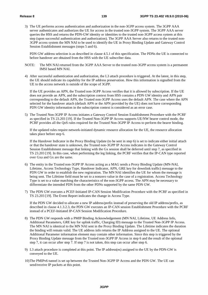
3GPP
3GPP TS 23.402 V8.9.0 (2010-06) 139Release 8
3) The UE performs access authentication and authorization in the non-3GPP access system. The 3GPP AAA server authenticates and authorizes the UE for access in the trusted non-3GPP system. The 3GPP AAA server queries the HSS and returns the PDN-GW identity or identities to the trusted non-3GPP access system at this step (upon successful authentication and authorization). The 3GPP AAA Server also returns to the trusted non-3GPP access system the MN NAI to be used to identify the UE in Proxy Binding Update and Gateway Control Session Establishment messages (steps 5 and 6).
PDN GW address selection is as described in clause 4.5.1 of this specification. The PDNs the UE is connected to before handover are obtained from the HSS with the UE subscriber data.
NOTE: The MN NAI returned from the 3GPP AAA Server to the trusted non-3GPP access system is a permanent IMSI based MN NAI.
4) After successful authentication and authorization, the L3 attach procedure is triggered. At the latest, in this step, the UE should indicate its capability for the IP address preservation. How this information is signalled from the UE to the access network is outside of the scope of 3GPP.
If the UE provides an APN, the Trusted non-3GPP Access verifies that it is allowed by subscription. If the UE does not provide an APN, and the subscription context from HSS contains a PDN GW identity and APN pair corresponding to the default APN, the Trusted non-3GPP Access uses the default APN. The case where the APN selected for the handover attach (default APN or the APN provided by the UE) does not have corresponding PDN GW identity information in the subscription context is considered as an error case.
5) The Trusted Non-3GPP IP Access initiates a Gateway Control Session Establishment Procedure with the PCRF as specified in TS 23.203 [19]. If the Trusted Non-3GPP IP Access supports UE/NW bearer control mode, the PCRF provides all the QoS rules required for the Trusted Non-3GPP IP Access to perform the bearer binding.
If the updated rules require network-initiated dynamic resource allocation for the UE, the resource allocation takes place before step 6.
If the Handover Indicator in the Proxy Binding Update (to be sent in step 6) is set to indicate either initial attach or that the handover state is unknown, the Trusted non-3GPP IP Access indicates in the Gateway Control Session Establishment message that linking with the Gx session shall be deferred until step 7, as specified in TS 23.203 [19]. In this case, when performing the leg linking, the PCRF verifies that the IP-CAN type reported over Gxa and Gx are the same.
6) The entity in the Trusted non-3GPP IP Access acting as a MAG sends a Proxy Binding Update (MN-NAI, Lifetime, Access Technology Type, Handover Indicator, APN, GRE key for downlink traffic) message to the PDN GW in order to establish the new registration. The MN NAI identifies the UE for whom the message is being sent. The Lifetime field must be set to a nonzero value in the case of a registration. Access Technology Type is set to a value matching the characteristics of the non-3GPP access. The APN may be necessary to differentiate the intended PDN from the other PDNs supported by the same PDN GW.
7) The PDN GW executes a PCEF-Initiated IP-CAN Session Modification Procedure with the PCRF as specified in TS 23.203 [19]. The Event Report indicates the change in Access Type.
If the PDN GW decided to allocate a new IP address/prefix instead of preserving the old IP address/prefix, as described in clause 4.1.3.2.3, the PDN GW executes an IP-CAN session Establishment Procedure with the PCRF instead of a PCEF-Initiated IP-CAN Session Modification Procedure.
8) The PDN GW responds with a PMIP Binding Acknowledgement (MN NAI, Lifetime, UE Address Info, Additional Parameters, GRE key for uplink traffic, Charging ID) message to the Trusted Non-3GPP IP Access. The MN NAI is identical to the MN NAI sent in the Proxy Binding Update. The Lifetime indicates the duration the binding will remain valid. The UE address info returns the IP Address assigned to the UE. The optional Additional Parameter information element may contain other information. Since this step is triggered by the Proxy Binding Update message from the Trusted non-3GPP IP Access in step 6 and the result of the optional step 7, it can occur after step 7. If step 7 is not taken, this step can occur after step 6.
9) L3 attach procedure is completed at this point. The IP address(es) assigned to the UE by the PDN-GW is conveyed to the UE.
10) The PMIPv6 tunnel is set up between the Trusted Non-3GPP IP Access and the PDN GW. The UE can send/receive IP packets at this point.

3GPP
3GPP TS 23.402 V8.9.0 (2010-06) 140Release 8
11) For connectivity to multiple PDNs, the UE establishes connectivity to all the PDNs that the UE was connected to before the handover besides the PDN connection that was established in the steps 3-10, as described in clause 6.8.1.
12) The PDN GW shall initiate the PDN GW Initiated PDN Disconnection procedure in 3GPP access as defined in clause 5.6.2.2 or the PDN GW Initiated Bearer Deactivation procedure as defined in TS 23.401 [4], clause 5.4.4.1.
8.2.3 E-UTRAN to Untrusted Non-3GPP IP Access Handover with PMIPv6 on S2b
This clause shows a call flow for a handover when a UE moves from an E-UTRAN to an untrusted non-3GPP access network. PMIPv6/GTP is assumed to be used on the S5/S8 interface and PMIPv6 is used on the S2b interface.
Serving GW
PDN GW UE ePDG MME hPCRF
1. Radio bearer and S1 bearer 1. PMIPv6/GTP tunnel
4. IKEv2 auth and tunnel setup
4. Authentication and Authorization (PDN GW)
5. Proxy BU (MN-NAI, IP Addr req)
7. Proxy BA (IP Addr)
PMIPv6 tunnel 8. IPsec tunnel setup completion
and address configuration
9. PMIPv6 tunnel 9. IPsec Tunnel
HSS/ AAA
vPCRF AAA Proxy
Roaming Scenarios
2. UE discovers Untrusted Non-
3GPP Access and initiates HO
6. PCEF-initiated IP-CAN Session Modification
Procedure
11. 3GPP EPS Bearer release
10. UE-initiated Connectivity to Additional PDN
11. 3GPP EPS Bearer release
Non-3GPP IP Access
3 Authenticatiion and authorisation 3. Access Authentication
Figure 8.2.3-1: E-UTRAN to Untrusted Non-3GPP IP Access Handover
Both the roaming (Figure 4.2.1-2) and non-roaming (Figure 4.2.1-1) scenarios are depicted in the figure. In the roaming case, the vPCRF acts as an intermediary, sending the QoS Policy Rules Provision from the hPCRF in the HPLMN to the Serving GW in the VPLMN. The vPCRF receives the Acknowledgment from the Serving GW and forwards it to the hPCRF. In the non-roaming case, the vPCRF is not involved.
For connectivity to multiple PDNs, step 9 is repeated for each PDN the UE is connected to. Step 9 can occur in parallel for each PDN. Other impacts related to the handover for multiple PDNs are described in clause 8.1.

3GPP
3GPP TS 23.402 V8.9.0 (2010-06) 141Release 8
The optional interaction steps between the gateways and the PCRF in the procedures only occur if dynamic policy provisioning is deployed. Otherwise policy may be statically configured in the gateway.
1) The UE is initially attached to the E-UTRAN network.
2) The UE moves and attaches to an untrusted non-3GPP IP access network.
3) Access authentication procedure between UE and the 3GPP EPC may be performed as defined by TS 33.402 [45].
4) The IKEv2 tunnel establishment procedure is started by the UE. The ePDG IP address to which the UE needs to form IPsec tunnel with is discovered as specified in clause 4.5.3. After the UE is authenticated, UE is also authorized for access to the APN. The procedure is as described in TS 33.234 [5]. As part of access authentication the PDN GW identity is sent to the ePDG by the 3GPP AAA server. If the UE supports IP address preservation during handover from E-UTRAN to the untrusted non-3GPP IP access, the UE shall include its address (IPv4 address or IPv6 prefix /address or both) allocated when it's attached to E-UTRAN into the CFG_Request sent to the ePDG during IKEv2 message exchange.
5) The ePDG sends the Proxy Binding Update (MN-NAI, Lifetime, Access Technology Type, Handover Indicator, GRE key for downlink traffic, UE Address Info, Additional Parameter) message to the PDN GW. Access Technology Type is set to a value matching the characteristics of the non-3GPP access. The UE Address Info shall be set according to the CFG_Request in step 3. The ePDG shall not change the requested address(es) in the CFG_Request sent by the UE, and encode such address(es) in PBU and send to the PDN GW. If the UE included the address in step 3, the ePDG sets the handover indicator to indicate Handoff between two different interfaces of the UE.
6) If PCC is supported, the PDN GW requires configuration for enforcing policy, the PDN GW executes a PCEF-Initiated IP CAN Session Modification Procedure with the PCRF as specified in TS 23.203 [19].
7) The PDN GW processes the Proxy Binding Update message from the ePDG, updates the binding cache entry for the UE and responds with a Proxy Binding Acknowledgement (MN_NAI, Lifetime, GRE key for uplink traffic, UE Address Info, Charging ID, Additional Parameters) message. In the Proxy Binding Ack, the PDN GW replies with the same IP address and/or prefix that was assigned to the UE earlier. At this point a PMIPv6 tunnel exists between PDN GW and ePDG. Since this step is triggered by the Proxy Binding Update message from the ePDG in step 4, it can occur after step 4 and does not need to wait for step 5.
8) The ePDG and the UE continue the IKEv2 exchange and IP address configuration.
9) At the end of the handover procedure there is a default bearer for the UE that consists of an IPsec tunnel between the UE and the ePDG and a PMIPv6 tunnel between the ePDG and the PDN GW.
10) For connectivity to multiple PDNs, the UE establishes connectivity to each PDN the UE was connected to before the handover, besides the PDN connection that was established in the steps 3-8, by executing the UE-initiated Connectivity to Additional PDN procedure specified in clause 7.6.1.
11) The PDN GW shall initiate the PDN GW Initiated PDN Disconnection procedure in 3GPP access as defined in clause 5.6.2.2 or the PDN GW Initiated Bearer Deactivation procedure as defined in TS 23.401 [4], clause 5.4.4.1.
8.2.4 Void
8.2.5 Void
8.2.6 Non-3GPP IP Access to 3GPP Access Handover with PMIPv6 on S2a/b for Chained PMIP-based S8
The steps involved in the handover from a trusted or non-trusted non-3GPP IP access to a 3GPP access connected to EPC are depicted below for roaming cases with chained S2a/b and PMIP-based S8. It is assumed that while the UE is

3GPP
3GPP TS 23.402 V8.9.0 (2010-06) 142Release 8
served by the non-3GPP IP access, a PMIPv6 tunnel is established between the non-3GPP access network and the Serving GW and another one between the Serving GW and the PDN GW.
New Serving GW
PDN GW hPCRF
UE
Trusted Non-3GPP IP Access 3GPP
Access MME
/SGSN Serving
GW HSS/ AAA
1. PMIPv6 Tunnel
vPCRF AAA Proxy
1. PMIPv6 Tunnel
/ ePDG
.
2. Procedure as per Figure 8.2.1.2-1 steps 2-18 (for E-UTRAN) or Figure 8.2.1.4-1 steps 2-16 (for UTRAN/GERAN)
3. Non-3GPP EPS bearer release 3. Non-3GPP EPS bearer release
Figure 8.2.6-1: Handover from Trusted or Untrusted Non-3GPP IP Access to 3GPP Access with chained S2a/b and PMIP-based S8
NOTE: The procedure applies both for the case where a new Serving GW is selected during attach on 3GPP access or for the case where the Serving GW is not changed.
1) The UE uses a trusted or untrusted non-3GPP access system. PDN connectivity is achieved through concatenated PMIPv6 tunnels between the trusted non-3GPP access or ePDG and the Serving GW, and between the Serving GW and the PDN GW.
2) The handover procedure from trusted or untrusted non-3GPP IP access with PMIPv6 on S2a/S2b to 3GPP access with PMIP-based S5/S8 is performed as described in steps 2-18 of clause 8.2.1.2 (for E-UTRAN) and steps 2-16 of clause 8.2.1.4 (for UTRAN/GERAN).
3) In case a new Serving GW has been selected during the attach on 3GPP access, the PDN GW triggers the bearer release in the non-3GPP access as defined in clause 6.12.3. Otherwise, the Serving GW triggers resource release in the non-3GPP access as defined in steps 2-5 of clause 6.12.3.
8.2.7 3GPP Access to Non-3GPP IP Access Handover with PMIPv6 on S2a/b for Chained PMIP-based S8
The steps involved in the handover from a 3GPP access to a trusted or non-trusted non-3GPP IP access connected to EPC are depicted below for roaming cases with chained S2a/b and PMIP-based S8.
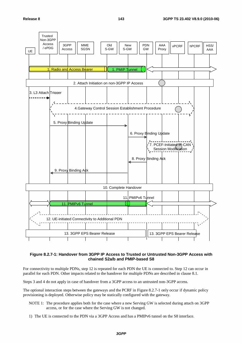
3GPP
3GPP TS 23.402 V8.9.0 (2010-06) 143Release 8
New S-GW
PDN GW
hPCRF UE
Trusted Non-3GPP
Access / ePDG
3GPP Access
MME SGSN
Old S-GW
HSS/ AAA
vPCRF AAA Proxy
5. Proxy Binding Update
.
6. Proxy Binding Update
10. Complete Handover
2. Attach Initiation on non-3GPP IP Access
11. PMIPv6 Tunnel 11. PMIPv6 Tunnel
1. PMIP Tunnel 1. Radio and Access Bearer
8. Proxy Binding Ack
9. Proxy Binding Ack
13. 3GPP EPS Bearer Release
12. UE-initiated Connectivity to Additional PDN
3. L3 Attach Trigger
4.Gateway Control Session Establishment Procedure
13. 3GPP EPS Bearer Release
7. PCEF-Initiated IP-CAN Session Modification
Figure 8.2.7-1: Handover from 3GPP IP Access to Trusted or Untrusted Non-3GPP Access with chained S2a/b and PMIP-based S8
For connectivity to multiple PDNs, step 12 is repeated for each PDN the UE is connected to. Step 12 can occur in parallel for each PDN. Other impacts related to the handover for multiple PDNs are described in clause 8.1.
Steps 3 and 4 do not apply in case of handover from a 3GPP access to an untrusted non-3GPP access.
The optional interaction steps between the gateways and the PCRF in Figure 8.2.7-1 only occur if dynamic policy provisioning is deployed. Otherwise policy may be statically configured with the gateway.
NOTE 1: The procedure applies both for the case where a new Serving GW is selected during attach on 3GPP access, or for the case where the Serving GW is not changed.
1) The UE is connected to the PDN via a 3GPP Access and has a PMIPv6 tunnel on the S8 interface.

3GPP
3GPP TS 23.402 V8.9.0 (2010-06) 144Release 8
2) The attach initiation on the trusted or untrusted non-3GPP access is performed as described in steps 2-3 of clause 8.2.2 (for trusted non-3GPP access) and steps 2-3 of clause 8.2.3 (for untrusted non-3GPP access). As part of the authentication procedure, the 3GPP AAA proxy obtains the PDN-GW identity from the HSS/AAA as described in clause 4.5.1, and performs Serving GW selection as described in clause 4.5.3. Both PDN GW identity and Serving GW information is provided to the MAG function of the trusted non-3GPP access or ePDG. If PCC is deployed, the MAG function of the Trusted Non-3GPP IP access is notified to interact with the PCRF when it is the PMIP-based chained case.
3) After successful authentication and authorization, the L3 attach procedure in the trusted non-3GPP access is triggered as described in step 4 of clause 8.2.2.
4) The trusted non-3GPP access initiates a Gateway Control Session Establishment Procedure with the PCRF as described in step 5 of clause 8.2.2.
5) The MAG function of Trusted Non-3GPP IP Access or ePDG sends a Proxy Binding Update (MN-NAI, Lifetime, Access Technology Type, Handover Indicator, APN, GRE key for downlink traffic, PDN GW address, Additional Parameters) message to the Serving GW in the VPLMN. The MN NAI identifies the UE. The Lifetime field must be set to a nonzero value, indicating registration. Access Technology Type is set to a value matching the characteristics of the non-3GPP access. Handover Indicator is set to indicate attachment over a new interface. The Additional Parameters may include Protocol Configuration Options and other information.
6) The Serving GW sends a corresponding Proxy Binding Update (MN-NAI, Lifetime, Access Technology Type, Handover Indicator, APN, GRE key for downlink traffic, Additional Parameters) message (as in step 3) to the PDN GW.
NOTE 2: In this Release of the specification, the Serving GW uses the right protocol to connect with the PDN GW based on the pre-configured information on itself in case the selected Serving GW supporting both PMIP and GTP.
7) The PDN GW initiates the PCEF-Initiated IP-CAN Session Modification Procedure with the hPCRF to update the rules in the PDN GW, as specified in TS 23.203 [19].
8) The PDN GW processes the proxy binding update and creates a binding cache entry for the PMIPv6 tunnel towards the Serving GW. The PDN GW responds with a Proxy Binding Acknowledgement (MN-NAI, Lifetime, UE Address Info, GRE key for uplink traffic, Additional Parameters) message to the Serving GW. The MN-NAI is identical to the MN-NAI sent in the Proxy Binding Update. The Lifetime indicates the duration the binding will remain valid. The UE Address Info includes one or more IP addresses. The Additional Parameters may include Protocol Configuration Options and other information.
9) The Serving GW processes the proxy binding acknowledgement and creates a binding cache entry for the PMIPv6 tunnel towards the MAG function in the trusted non-3GPP access or ePDG. At this point, the Serving GW also establishes the internal forwarding state for the concatenation of the PMIPv6 tunnels. The Serving GW then sends a corresponding Proxy Binding Acknowledgement (MN NAI, Lifetime, UE Address Info, GRE key for uplink traffic, Charging ID, Additional Parameters) message (as in step 8) to the MAG function of Trusted Non-3GPP IP Access or ePDG.
10) The handover attach procedure is completed as described in step 9 of clause 8.2.2 (for trusted non-3GPP access) and steps 7-8 of clause 8.2.3 (for untrusted non-3GPP access).
11) The UE is connected to the PDN via the non-3GPP access system. PDN connectivity is achieved through concatenated PMIPv6 tunnels between the trusted non-3GPP access or ePDG and the Serving GW, and between the Serving GW and the PDN GW.
12) For connectivity to multiple PDNs, the UE establishes connectivity to each PDN the UE was connected to before the handover, besides the PDN connection established in steps 2-11, by executing the UE-initiated Connectivity to Additional PDN procedure specified in clause 6.8.1.2, that applies to both trusted and untrusted non-3GPP accesses.
13) In case a new Serving GW has been selected during the attach on the non-3GPP access, the PDN GW triggers the bearer release in the 3GPP access using the PDN GW initiated Bearer Deactivation procedure. Otherwise, the Serving GW triggers the bearer release in the 3GPP Access using the Serving GW initiated Bearer Deactivation procedure. The 3GPP access resources associated with the PDN address are released if existing.

3GPP
3GPP TS 23.402 V8.9.0 (2010-06) 145Release 8
8.2.8 Void
8.2.9 Void
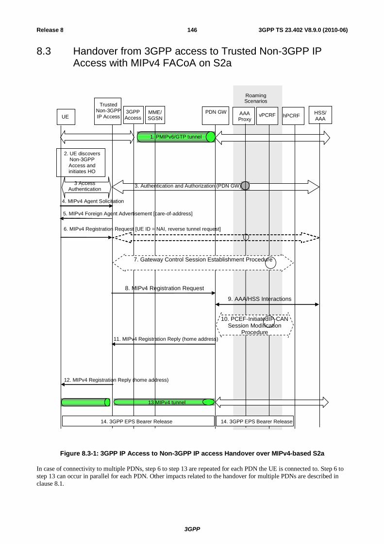
3GPP
3GPP TS 23.402 V8.9.0 (2010-06) 146Release 8
8.3 Handover from 3GPP access to Trusted Non-3GPP IP Access with MIPv4 FACoA on S2a
PDN GW UE
Trusted Non-3GPP IP Access hPCRF
1. PMIPv6/GTP tunnel
3 Access Authentication .
3. Authentication and Authorization (PDN GW)
13 MIPv4 tunnel
2. UE discovers Non-3GPP Access and initiates HO
HSS/ AAA
vPCRF AAA Proxy
Roaming Scenarios
3GPP Access
MME/ SGSN
14. 3GPP EPS Bearer Release 14. 3GPP EPS Bearer Release
4. MIPv4 Agent Solicitation
5. MIPv4 Foreign Agent Advertisement [care-of-address]
6. MIPv4 Registration Request [UE ID = NAI, reverse tunnel request]
11. MIPv4 Registration Reply (home address)
12. MIPv4 Registration Reply (home address)
7. Gateway Control Session Establishment Procedure
10. PCEF-InitiatedIP-CAN Session Modification
Procedure
8. MIPv4 Registration Request
9. AAA/HSS Interactions
Figure 8.3-1: 3GPP IP Access to Non-3GPP IP access Handover over MIPv4-based S2a
In case of connectivity to multiple PDNs, step 6 to step 13 are repeated for each PDN the UE is connected to. Step 6 to step 13 can occur in parallel for each PDN. Other impacts related to the handover for multiple PDNs are described in clause 8.1.

3GPP
3GPP TS 23.402 V8.9.0 (2010-06) 147Release 8
The steps involved in the handover from 3GPP Access connected to the EPC to trusted non-3GPP IP access are depicted below for the case of non-roaming, roaming with home routed traffic, roaming with local breakout and roaming with anchoring in the Serving Gateway in the VPLMN. It is assumed that while the UE is served by the 3GPP Access, a PMIPv6 or GTP tunnel is established between the S-GW and the PDN GW in the evolved packet core.
The optional interaction steps between the gateways and the PCRF in the procedures only occur if dynamic policy provisioning is deployed. Otherwise policy may be statically configured with the gateway.
Both the roaming (Figure 4.2.1-2) and non-roaming (Figure 4.2.1-1) scenarios are depicted in the figure. In the roaming case, the vPCRF acts as an intermediary, sending the QoS Policy Rules Provision from the hPCRF in the HPLMN to the Serving GW in the VPLMN. The vPCRF receives the Acknowledgment from the Serving GW and forwards it to the hPCRF. In the non-roaming case, the vPCRF is not involved at all.
The event that triggers Authentication and Authorization in step 3 or step 6 between the Trusted Non-3GPP IP Access and the 3GPP AAA Server, or whether this step occurs at all, depends on the specific access technology.
1) The UE is connected in the 3GPP Access and has a PMIPv6 or GTP tunnel on the S5 interface.
2) The UE discovers the trusted non-3GPP IP access system and determines to transfer its current sessions (i.e. handover) from the currently used 3GPP Access to the discovered trusted non-3GPP IP access system. The mechanisms that aid the UE to discover the trusted non-3GPP IP access system, are specified in clause 4.8 (Network Discovery and Selection).
3) The UE performs access authentication and authorization in the non-3GPP access system as defined by TS 33.402 [45]. The 3GPP AAA server authenticates and authorizes the UE for access in the trusted non-3GPP system. As part of the authentication and authorization procedure, the 3GPP AAA server obtains the PDN-GW identity from the HSS and it returns the same PDN-GW identity to the trusted non-3GPP access system at this step (upon successful authentication and authorization).
4) The UE may send an Agent Solicitation (AS) RFC 3344 [12] message. Specification of this message is out of the scope of 3GPP.
5) The FA in the Trusted Non-3GPP IP Access sends a Foreign Agent Advertisement (FAA) (RFC 3344 [12]) message to the UE. The FAA message includes the Care-of Address (CoA) of the Foreign Agent function in the FA. Specification of this message is out of the scope of 3GPP.
6) The UE sends a Registration Request (RRQ) (MN-NAI, lifetime) message as defined in RFC 3344 [12] to the FA as specified in RFC 3344 [12]. Reverse Tunnelling shall be requested. This ensures that all traffic will go through the PDN GW. The RRQ message shall include the NAI-Extension RFC 2794 [34]. The UE may not indicate a specific Home Agent address in the RRQ message, in which case the FA uses the PDN GW address as received in step 3. The UE then receives the IP address of the PDN Gateway in step 11 as part of the RRP message. The UE should then include the PDN Gateway address in the Home Agent address field of subsequent RRQ messages.
7) The Trusted non-3GPP access initiates the Gateway Control Session Establishment Procedure with the PCRF. The Trusted non-3GPP access provides the information to the PCRF to correctly associate it with the IP-CAN session and also to convey subscription related parameters to the PCRF. If the Trusted Non-3GPP access supports UE/NW bearer control mode, the PCRF provides all the QoS rules required for the Trusted Non-3GPP access to perform the bearer binding.
8) The FA processes the message according to RFC 3344 [12] and forwards a corresponding RRQ (MN-NAI, lifetime) message to the PDN GW.
9) The selected PDN GW obtains Authentication and Authorization information from the AAA/HSS.
10) The PDN GW allocates an IP address for the UE. The PDN GW initiates the IP CAN Session Modification Procedure with the PCRF, as specified in TS 23.203 [19]. The PDN GW provides information to the PCRF that the IP-CAN type has changed and the PCRF responds to the PDN GW with PCC rules and event triggers.
11) The PDN GW sends a Registration Reply (RRP) (MN-NAI, Home Address, Home Agent Address) message as defined in RFC 3344 [12] to the FA.
12) The FA processes the RRP (MN-NAI, Home Address) according to RFC 3344 [12] and sends a corresponding RRP message to the UE.

3GPP
3GPP TS 23.402 V8.9.0 (2010-06) 148Release 8
13) IP connectivity from the UE to the PDN GW is now setup. A MIP tunnel is established between the FA in the Trusted Non-3GPP IP Access and the PDN GW.
14) The PDN GW shall initiate the PDN GW Initiated PDN Disconnection procedure in 3GPP access as defined in clause 5.6.2.2 or the PDN GW Initiated Bearer Deactivation procedure as defined in TS 23.401 [4], clause 5.4.4.1.
8.4 Handovers with DSMIPv6 on S2c
8.4.1 Trusted or Untrusted Non-3GPP IP Access with DSMIPv6 over S2c to 3GPP Access Handover
In this scenario, the session starts in a trusted or untrusted non-3GPP access system using DSMIPv6 and subsequently, the session hands over to a 3GPP access system.
The steps involved in the handover from a trusted/untrusted non-3GPP IP access to 3GPP Access connected to EPC are depicted below when DSMIPv6 is used on S2c over non-3GPP system.
PDN GW AAA Proxy
HSS/ AAA UE
Trusted Non-
3GPP IP Access/ ePDG
EUTRAN MME Serving GW
hPCRF
1. DSMIPv6 Tunnel
3. BU (DSMIPv6 deregistration with lifetime=0), BA
vPCRF
2. 3GPP Attach and Bearer Setup as defined in Step (C) of Figure 8.2.1.1-1
Roaming Scenario
4. PCRF initiated Gateway Control Session Termination Procedure
Figure 8.4.1-1: Trusted Non-3GPP S2c (DSMIPv6) to 3GPP with S5 handover
For connectivity to multiple PDNs, step 18 of Figure 8.2.1.1-1 and steps 3 of Figure 8.4.1-1 are repeated for each PDN the UE is connected to. Other impacts related to the handover for multiple PDNs are described in clause 8.1.
The optional interaction steps between the gateways and the PCRF in the procedures only occur if dynamic policy provisioning is deployed. Otherwise policy may be statically configured with the gateway.
1) The UE uses a trusted or untrusted non-3GPP access system. It has a DSMIPv6 session with the PDN GW.
2) The UE discovers and attaches to the 3GPP access as defined in Step (C) of Figure 8.2.1.1-1, except that the IP-CAN session modification and the path switch are triggered as explained below.
3) The UE sends a BU (lifetime) to the PDN GW to de-register its DSMIPv6 binding, as defined in RFC 5555 [10] that was created while the UE was in non-3GPP access system. The UE shall inform the PDN GW that the whole home prefix shall be moved. The PDN GW responds with a BA message as defined in RFC 5555 [10].
Any time after step 2, prior to receiving the de-registration Binding Update from the UE (i.e. BU with lifetime = 0), which is received in (step 3), the PDN GW may de-register the DSMIPv6 binding. In this case the PDN GW shall send a Binding Revocation Indication message to the UE.
Following the de-registration of the DSMIPv6 binding due to reception of de-registration Binding update or due to triggering Binding Revocation, the PDN GW triggers PCEF initiated IP-CAN session modification, instead of

3GPP
3GPP TS 23.402 V8.9.0 (2010-06) 149Release 8
doing it as part of the step 2, and performs path switch to forward downlink packets to the UE without any tunnelling (as the UE is on the home link).
4) The PCRF initiates "PCRF-initiated Gateway Control Session Termination" procedure to release the resources in the non-3GPP access. This procedure is triggered by the PCEF-Initiated IP-CAN Session Modification Procedure with the PCRF.
According to RFC 4877 [22] the security associations between the UE and the PDN GW(s) should not be immediately deleted. As the security associations were created dynamically using IKEv2 they will be automatically deleted when they expire. The IP address used by the UE as home address is not released by the UE and the PDN GW as a result of the deletion of such security associations if the UE remains connected to the PDN GW. This applies also to the scenario where the UE performed the initial attach over a 3GPP access and was given a IP address, bootstrapped the DSMIPv6 over the 3GPP access, performed an handover to the non-3GPP access using S2c, and is now performing an handover towards 3GPP access and therefore returning to the Home Link.
8.4.2 3GPP Access to Trusted Non-3GPP IP Access Handover with DSMIPv6 over S2c
In this scenario, the session starts in 3GPP access (e.g. E-UTRAN) using PMIPv6 or GTP over S5 or no S5 is used (co-located Serving GW and PDN GW). The session hands over to the trusted non-3GPP access system that does not use PMIPv6 where the UE will receive a different prefix than the one it was using in 3GPP access system. The UE subsequently initiates DSMIPv6 with the same PDN GW to maintain the IP session.
Support of PCC for Trusted non-3GPP accesses is optional. The PCC interactions shown in Figure 8.4.2-1 are omitted if the Trusted non-3GPP access does not support PCC. If PCC is not supported, policy rules may be configured by other means.
In the non-roaming case, none of the optional entities in Figure 8.4.2-1 are involved.
The optional entities are involved in other cases.
- In the roaming cases, however, the 3GPP AAA Proxy mediates all interaction between the 3GPP AAA Server in the PLMN and entities in the VPLMN and non-3GPP access.
- Similarly, interaction between hPCRF in the HPLMN and entities in the VPLMN and non-3GPP access occurs by way of the vPCRF in the VPLMN. In both these cases, messages are relayed by the optional entities towards and from the HPLMN.

3GPP
3GPP TS 23.402 V8.9.0 (2010-06) 150Release 8
Serving GW
PDN GW UE
Trusted Non-
3GPP IP Access
hPCRF
1. PMIPv6/ GTP Tunnel
3. Access Authentication
3. Authentication and Authorization (PDN GW)
7. Binding Update
9. Binding Acknowledgement
4. L3 Attach & Local IP Address
Allocation
11. DSMIPv6 tunnel
2. UE discovers Trusted Non-3GPP Access and initiates
HO
HSS/ AAA
vPCRF AAA Proxy
Roaming Scenarios
6. DSMIPv6 bootstrapping
(A) 5. Gateway Control Session Establishment Procedure
8. PCEF-initiated IP-CAN Session Modification Procedure
12. 3GPP EPS Bearer release
10. Gateway Control and QoS Rules Provision Procedure
Figure 8.4.2-1: 3GPP S5 to Trusted Non-3GPP S2c (DSMIPv6) Handover
In case of connectivity to multiple PDNs, Steps 6 to 9 are repeated for each PDN the UE is connected to. Other impacts related to the handover for multiple PDNs are described in clause 8.1
1) The UE uses a 3GPP access system. It has an IP address that is supported over S5 interface, this IP address will be used as a HoA over the S2c reference point.
2) At this point the UE decides to initiate non-3GPP access procedure. The decision is based on any number of reasons e.g. local policies of the UE.
3) The UE shall perform access authentication and authorization in the non-3GPP access system as defined by TS 33.402 [45] unless the conditions in TS 33.402 [45] are met that allow to skip this procedure. In the roaming case signalling may be routed via a 3GPP AAA Proxy in the VPLMN, as specified in TS 23.234 [5]. As part of the AAA exchange for network access authentication, the 3GPP AAA Server and/or the 3GPP AAA Proxy may return to the non-3GPP access system a set of home/visited operator's policies to be enforced on the usage of local IP address, or IPv6 prefix, allocated by the access system upon successful authentication.
4) The L3 connection is established between the UE and the Trusted Non-3GPP Access system. As a result of this procedure, an IPv4 address or an IPv6 address/prefix is also assigned to the UE by the access system (i.e. a Local IP address that will be used as a Care-of Address for DSMIPv6 over the S2c reference point).

3GPP
3GPP TS 23.402 V8.9.0 (2010-06) 151Release 8
5) The Trusted non-3GPP IP Access initiates a Gateway Control Session Establishment Procedure with the PCRF as specified in TS 23.203 [19].
Based e.g. on the UE identity and user profile, operator's policies and the IP-CAN type, the PCRF decides on the QoS policy rules and completes the GW control session establishment towards the access gateway (5b)
In the roaming case, PCC signalling is sent via a vPCRF server in the VPLMN
6) If bootstrapping was not performed prior to the handover defined here, the UE may discover PDN GW address using MIPv6 bootstrapping procedures defined in clause 4.5.2. If the PDN GW discovered by the UE upon MIPv6 bootstrapping is different from the PDN GW that was in use on the 3GPP access, a PDN GW reallocation as per steps 2-3 in clause 6.10 is performed. The target PDN GW that is communicated to the UE as part of the reallocation procedure must be exactly the PDN GW that was serving the UE while on the 3GPP access.
7) The UE sends a DSMIPv6 BU message to the PDN GW to register its CoA, the CoA is the local IP address allocated in step 4. The UE shall inform the PDN GW that the whole home prefix shall be moved.
8) If PCC is supported, the PDN GW executes a PCEF-Initiated IP CAN Session Modification Procedure with the PCRF as specified in TS 23.203 [19].
In the roaming case, PCC signalling is sent via a vPCRF server in the VPLMN.
9) The PDN GW sends the MIP Binding Ack to the UE. Since this step is triggered by the Binding Update message from the UE in step 7, it can occur after step 7 and does not need to wait for step 8.
The PDN GW may send message 9 before the procedure in step message 8 is complete.
10) The PCRF initiates the Gateway Control and QoS Rules Provision Procedure specified in TS 23.203 [19] by sending a message with the information of mobility protocol tunnelling encapsulation header to the Trusted non-3GPP IP Access. In case the QoS rules have changed, the updated QoS rules shall also be included in this message.
11) The UE continues with IP service using the same IP address in step 1.
12) The PDN GW shall initiate the PDN GW Initiated PDN Disconnection procedure in 3GPP access as defined in clause 5.6.2.2 or the PDN GW Initiated Bearer Deactivation procedure as defined in TS 23.401 [4], clause 5.4.4.1.
8.4.3 3GPP Access to Untrusted Non-3GPP IP Access Handover with DSMIPv6 over S2c
In this scenario, the session starts in 3GPP access (e.g. E-UTRAN) using either GTP or PMIPv6 is used over S5, or no S5 is used (co-located Serving GW and PDN GW). ). In the roaming case instead of S5, S8 is used. The session hands over to an untrusted non-3GPP access system that does not use PMIPv6 where the UE will receive a different prefix from the ePDG than the one it was using in 3GPP access system The UE subsequently initiates DSMIPv6 with the its PDN GW to maintain the IP session.
Support of PCC for Untrusted non-3GPP accesses is optional. The PCC interactions shown in Figure 8.4.3-1 are omitted if the Untrusted non-3GPP access does not support PCC. If PCC is not supported, policy rules may be configured by other means.
In the non-roaming case, none of the optional entities in Figure 8.4.3-1 are involved.
The optional entities are involved in other cases.
- In the roaming cases, however, the 3GPP AAA Proxy mediates all interaction between the 3GPP AAA Server in the PLMN and entities in the VPLMN and non-3GPP access.
- Similarly, interaction between hPCRF in the HPLMN and entities in the VPLMN and non-3GPP access occurs by way of the vPCRF in the VPLMN. In both these cases, messages are relayed by the optional entities towards and from the HPLMN.

3GPP
3GPP TS 23.402 V8.9.0 (2010-06) 152Release 8
Serving GW
PDN GW UE ePDG hPCRF
1. PMIPv6/ GTP tunnel
4. IKEv2 auth and tunnel setup
4. Authentication and Authorization (PDN GW)
7. Binding Update
9. Binding Acknowledgement
DSMIPv6 tunnel IPsec Tunnel
2. UE discovers Untrusted Non-
3GPP Access and initiates HO
HSS/ AAA
vPCRF AAA Proxy
Roaming Scenarios
IPsec Tunnel
6. DSMIPv6 bootstrapping
10. IPSec and DSMIPv6 Tunnels
11. 3GPP EPS Bearer Release
8. PCEF-initiated IP-CAN Session Modification Procedure
5. IKEv2 (IP address)
Non-3GPP IP Access
3. Authentication and Authorization 3.Access Authentication
Figure 8.4.3-1: 3GPP Access to Untrusted Non-3GPP IP Access with S2c (DSMIPv6) Handover
In case of connectivity to multiple PDNs, Steps 6 to 8 are repeated for each PDN the UE is connected to. Other impacts related to the handover for multiple PDN GWs are described in clause 8.1
1. The UE uses a 3GPP access system. It has an IP address that is supported over S5 interface, this IP address will be used as a HoA over the S2c reference point.
2. At this point the UE decides to initiate non-3GPP access procedure. The decision is based on any number of reasons e.g. local policies of the UE.
3 Access authentication procedure between UE and the 3GPP EPC may be performed as defined by TS 33.402 [45].
4. The IKEv2 tunnel establishment procedure is started by the UE. The UE may indicate in a notification part of the IKEv2 authentication request that it supports MOBIKE. The ePDG IP address to which the UE needs to form IPsec tunnel is discovered via DNS query as specified in clause 4.5.4. After the UE is authenticated, UE is also authorized for access to the APN. The procedure is as described in TS 33.234 [7].
NOTE: It is assumed that the access system is aware that network-based mobility procedures do not need to be initiated.
5. The ePDG sends the final IKEv2 message with the assigned IP address in IKEv2 Configuration payloads. The IKEv2 procedure is completed and the IPSEC tunnel is set-up. In this procedure, the assigned IP address is an

3GPP
3GPP TS 23.402 V8.9.0 (2010-06) 153Release 8
IPv4 address or an IPv6 prefix assigned to the UE by the ePDG and the assigned IP address that will be used as a Care-of Address for DSMIPv6 over the S2c reference point.
6. If bootstrapping was not performed prior to the handover defined here, the UE may discover PDN GW address using DSMIPv6 bootstrapping procedures defined in clause 4.5.2. If the PDN GW discovered by the UE upon MIPv6 bootstrapping is different from the PDN GW that was in use on the 3GPP access, a PDN GW reallocation as per steps 2-3 in clause 6.10 is performed. The target PDN GW that is communicated to the UE as part of the reallocation procedure must be exactly the PDN GW that was serving the UE while on the 3GPP access.
7. The UE sends a DSMIPv6 BU message to the PDN GW to register its CoA. The UE shall inform the PDN GW that the whole home prefix shall be moved.
8. If PCC is supported, the PDN GW executes a PCEF-Initiated IP CAN Session Modification Procedure with the PCRF as specified in TS 23.203 [19] to obtain the rules required for the PDN GW in the VPLMN or HPLMN to function as the PCEF for all the active sessions the UE has established with the new IP-CAN type as a result of the handover procedure.
9. The PDN GW sends the DSMIPv6 Binding Ack to the UE. Since this step is triggered by the Binding Update message from the UE in step 6, it can occur after step 6 and does not need to wait for step 7.
The PDN GW may send message 8 before the procedure in step 8 is complete.
10. The UE continues with IP service using the same IP address in step 1.
11. The PDN GW shall initiate the PDN GW Initiated PDN Disconnection procedure in 3GPP access as defined in clause 5.6.2.2 or the PDN GW Initiated Bearer Deactivation procedure as defined in TS 23.401 [4], clause 5.4.4.1.
8.5 Handover with Access Network Discovery and Selection
8.5.1 Handover between 3GPP Access and Trusted / Untrusted Non-3GPP IP Access with access network discovery and selection
The figure below shows the main steps involved in a handover between a 3GPP access and a non-3GPP IP access (also called an inter-system handover) when network discovery and selection information is provided by the network (see clause 4.8). This information is provided in order to control the UE's inter-system handover decisions and in order to reduce the battery consumption for inter-system mobility.

3GPP
3GPP TS 23.402 V8.9.0 (2010-06) 154Release 8
UE ANDSF
3. Access Network Info Request
4. Access Network Info Response
1. UE connected with the EPC over a 3GPP or non - 3GPP access
5. UE makes access network selection and handover decision
6. UE initiates the inter - system handover
2. Discover ANDSF and establish secure communication
Figure 8.5.1-1: Handover between 3GPP Access and trusted / untrusted non-3GPP IP Access with Access Network Discovery and Selection
1. The UE is connected with a source access network (either a 3GPP access or a trusted / untrusted non-3GPP IP access). Its radio interfaces not connected to any access network may be in power saving or powered down mode.
2. If the inter-system mobility policies (see clause 4.8) in the UE indicate that inter-system mobility is allowed with at least one access technology type, then the UE may decide to discover neighbour access networks with assistance by the network. In this case, the UE discovers the address of ANDSF (if needed) as specified in clause 4.8, establishes secure communication with the ANDSF as specified in TS 33.402 [45] and requests access network info from the ANDSF as specified in the steps below.
3. The UE sends an Access Network Info Request (UE Capabilities, UE Location) message to the ANDSF to retrieve network discovery and selection information. The UE Capabilities indicate the capabilities of the UE pertaining to access network discovery, such as the access technology types that can be supported by the UE. If the UE Location is available in the UE, it should be included in the message to indicate the UE's current location, e.g. for the 3GPP access, Cell ID, TAI, and/or GPS (if available). If the UE Location is not included then other mechanisms may be used by ANDSF to identify the UE's current location.
NOTE 1: In this release of the specification, no mechanisms are specified for the ANDSF to identify the UE's current location, if this information is not provided by the UE.
4. The ANDSF responds with an Access Network Info Response (Available Access Network Info, Updated Inter-system Mobility Policies) message to the UE. The Available Access Networks Info contains a list of access networks that are available in the vicinity of UE. If the UE included one or more access technology types in the Access Network Info Request, then information about neighbour access network with the requested access technology types is included. The Updated Inter-system Mobility Policies may be included in order to update / install operator defined rules / preferences in the UE. These rules / preferences may indicate a preference value for an available access network and help the UE select an available access network that is more preferable to the current access network.
5. The UE powers up its appropriate radio interface(s) (if needed) and measures the available access networks for which inter-system mobility is allowed, as indicated by the updated / current inter-system mobility policies. The
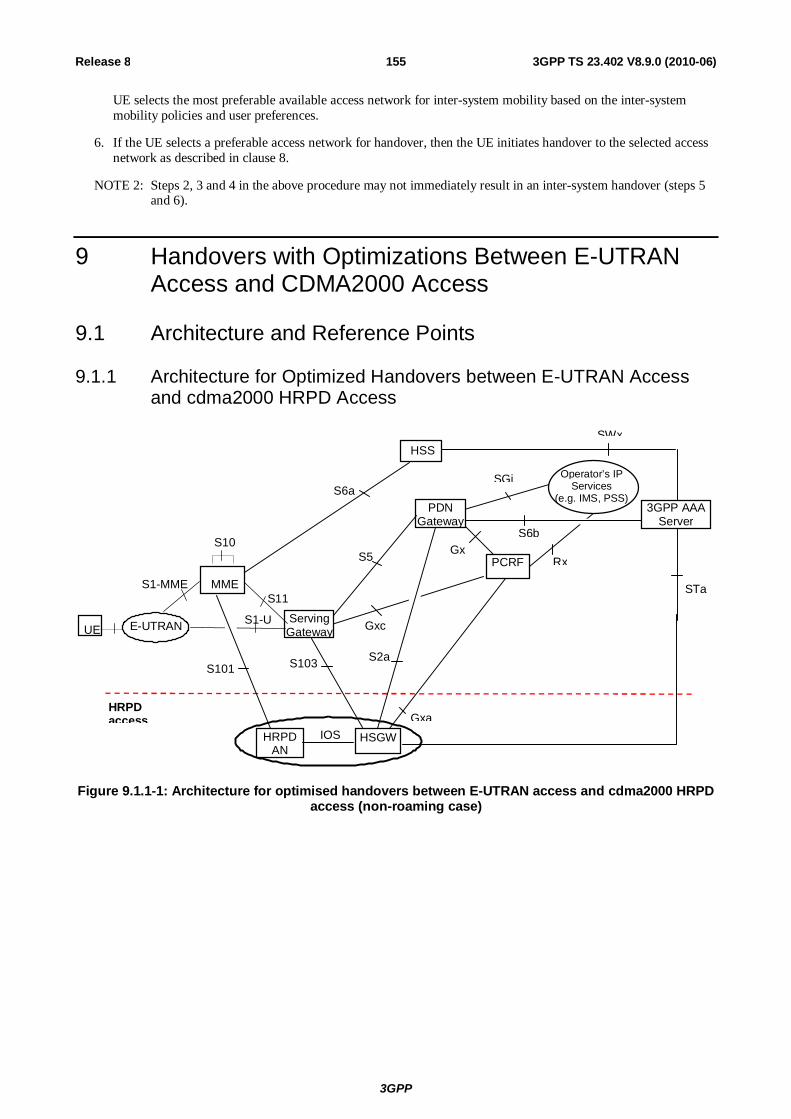
3GPP
3GPP TS 23.402 V8.9.0 (2010-06) 155Release 8
UE selects the most preferable available access network for inter-system mobility based on the inter-system mobility policies and user preferences.
6. If the UE selects a preferable access network for handover, then the UE initiates handover to the selected access network as described in clause 8.
NOTE 2: Steps 2, 3 and 4 in the above procedure may not immediately result in an inter-system handover (steps 5 and 6).
9 Handovers with Optimizations Between E-UTRAN Access and CDMA2000 Access
9.1 Architecture and Reference Points
9.1.1 Architecture for Optimized Handovers between E-UTRAN Access and cdma2000 HRPD Access
PCRF
HSS
PDN Gateway
HRPD access
STa
3GPP AAA Server
S2a
Gxa
SGi
GxS6b
Operator’s IP Services
(e.g. IMS, PSS)
Rx
SWx
Gxc
S5
S6a
Serving Gateway
HRPD AN
HSGW IOS
S1-U
MME
S10
S11
UE E-UTRAN
S1-MME
S101 S103
Figure 9.1.1-1: Architecture for optimised handovers between E-UTRAN access and cdma2000 HRPD access (non-roaming case)

3GPP
3GPP TS 23.402 V8.9.0 (2010-06) 156Release 8
hPCRF
HSS
PDN Gateway HPLMN
SWd
HRPD access
VPLMN
vPCRF
3GPP AAA Proxy
STa
3GPP AAA Server
S2a
Gxa
S9
SGi
Gx
S6b
Operator’s IP Services
(e.g. IMS, PSS)
Rx
SWx
Gxc
S8
S6a
Serving Gateway
HRPD AN
HSGW IOS
S1-U
MME
S10
S11
E-UTRAN UE
S1-MME
S101 S103
Figure 9.1.1-2: Architecture for optimised handovers between E-UTRAN access and cdma2000 HRPD access (roaming case; Home routed)
NOTE 1: Optimized handover supported by this architecture is intended for the scenario where the operator owns both the E-UTRAN access and the HRPD access, or where there is a suitable inter-operator agreement in place.
NOTE 2: Gxc is used only in the case of PMIP variant of S5 or S8.
NOTE 3: For further specification of the functions and interfaces of the HRPD Serving GW (HS-GW) refer to 3GPP2 X.P0057 [51]. The HRPD in this specification refers to the evolved HRPD as defined in 3GPP2 X.P0057 [51].
Depicted in Figure 9.1.1-1 is an access specific architecture providing support for optimised E-UTRAN-HRPD handovers. in the non-roaming case. Depicted in figure 9.1.1-2 is an access specific architecture providing support for optimised E-UTRAN-HRPD handovers in the roaming case with Home routed traffic.
9.1.2 Reference Points
9.1.2.1 Reference Point List
S101: It enables interactions between EPS and HRPD access to allow for pre-registration and handover signalling with the target system.
S103: This User Plane interface is used to forward DL data to minimize packet losses in mobility from E-UTRAN to HRPD.
9.1.2.2 Requirements for the S101 Reference Point
The S101 interface supports procedures for Pre-Registration, Session Maintenance and Active handovers between E-UTRAN and HRPD networks. This is based on tunnelling over S101 signalling of one technology while the UE is in the other technology. The HRPD air interface messages tunnelled over S101 in E-UTRAN to HRPD mobility are defined in 3GPP2 C.S0087-0 [49].
The S101 reference point shall support the following requirements:
- HRPD and E-UTRAN/EPS messages shall be transported as opaque containers without modifications by the MME or HRPD AN.
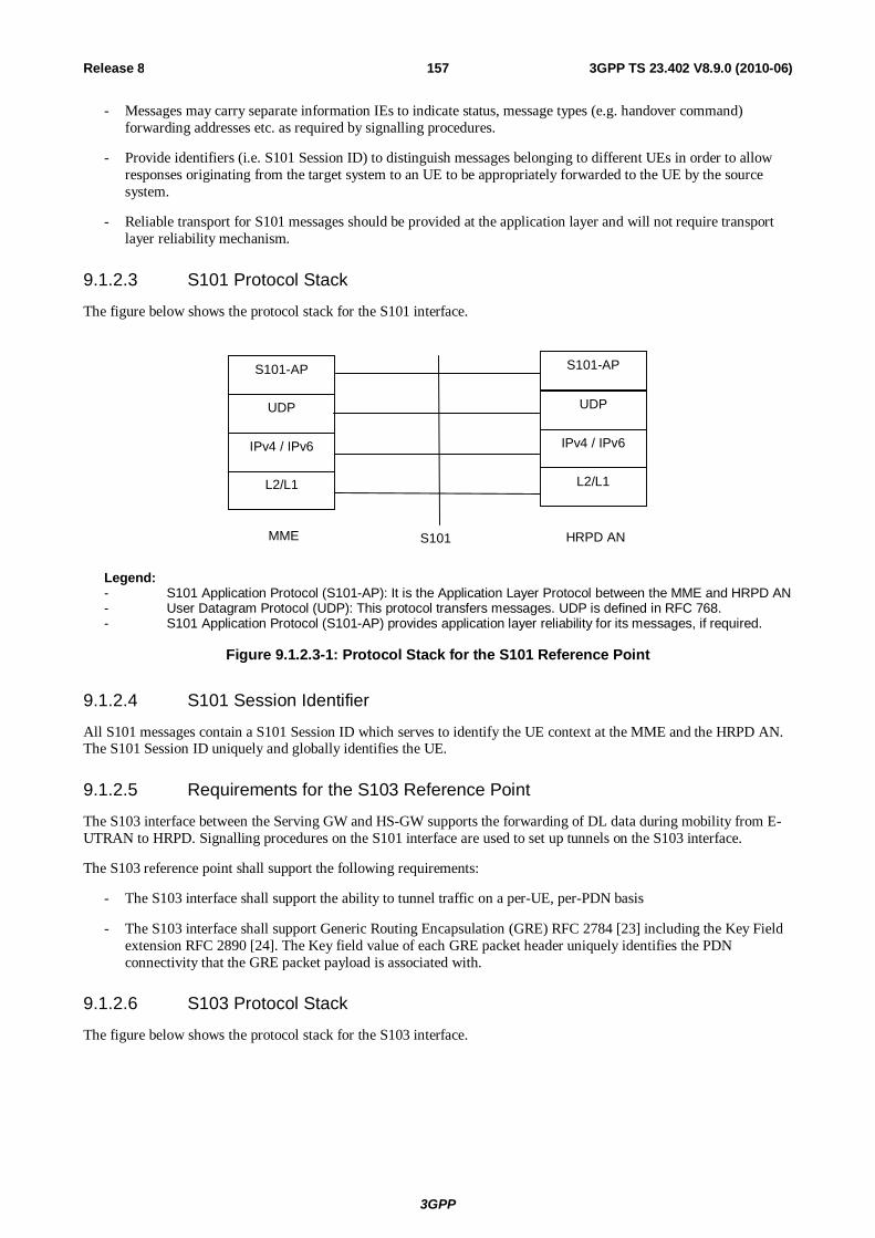
3GPP
3GPP TS 23.402 V8.9.0 (2010-06) 157Release 8
- Messages may carry separate information IEs to indicate status, message types (e.g. handover command) forwarding addresses etc. as required by signalling procedures.
- Provide identifiers (i.e. S101 Session ID) to distinguish messages belonging to different UEs in order to allow responses originating from the target system to an UE to be appropriately forwarded to the UE by the source system.
- Reliable transport for S101 messages should be provided at the application layer and will not require transport layer reliability mechanism.
9.1.2.3 S101 Protocol Stack
The figure below shows the protocol stack for the S101 interface.
UDP
IPv4 / IPv6
L2/L1
MME
S101-AP
UDP
IPv4 / IPv6
L2/L1
HRPD AN
S101-AP
S101
Legend: - S101 Application Protocol (S101-AP): It is the Application Layer Protocol between the MME and HRPD AN - User Datagram Protocol (UDP): This protocol transfers messages. UDP is defined in RFC 768. - S101 Application Protocol (S101-AP) provides application layer reliability for its messages, if required.
Figure 9.1.2.3-1: Protocol Stack for the S101 Reference Point
9.1.2.4 S101 Session Identifier
All S101 messages contain a S101 Session ID which serves to identify the UE context at the MME and the HRPD AN. The S101 Session ID uniquely and globally identifies the UE.
9.1.2.5 Requirements for the S103 Reference Point
The S103 interface between the Serving GW and HS-GW supports the forwarding of DL data during mobility from E-UTRAN to HRPD. Signalling procedures on the S101 interface are used to set up tunnels on the S103 interface.
The S103 reference point shall support the following requirements:
- The S103 interface shall support the ability to tunnel traffic on a per-UE, per-PDN basis
- The S103 interface shall support Generic Routing Encapsulation (GRE) RFC 2784 [23] including the Key Field extension RFC 2890 [24]. The Key field value of each GRE packet header uniquely identifies the PDN connectivity that the GRE packet payload is associated with.
9.1.2.6 S103 Protocol Stack
The figure below shows the protocol stack for the S103 interface.

3GPP
3GPP TS 23.402 V8.9.0 (2010-06) 158Release 8
GRE TunnellingL ayer
IPv4 / IPv6
L2/L1
Serving GW
HSGWS103
GRE TunnellingLayer
IPv4 / IPv6
L2/L1
Figure 9.1.2.6-1: Protocol Stack for the S103 Reference Point
Legend:
- On the S103 interface, the tunnelling layer implements GRE encapsulation with the Key Field extension RFC 2784 [23], RFC 2890 [24].
9.2 Overview of Handover Procedures The S101 reference point, and E-UTRAN and HRPD access is used for transparent transfer of pre-registration and handover signalling between the UE and the target access system
The purpose of the procedures is to minimise the total service interruption time experienced at the UE, by allowing the UE to attach and perform service activation (in the case of E-UTRAN) or to perform a session configuration or traffic allocation request (in the case of HRPD) in the target access system before leaving the source access system.
In case where the UE is connected to the E-UTRAN and conditions are such that a handover to HRPD may be required, the source system provides the UE with sufficient information to perform pre-registration with the target HRPD access and core network, over the S101 tunnelling interface. If conditions subsequently warrant that a handover should occur, the handover signalling will also be performed over the S101 tunnelling interface. Once the UE is ready to connect to the target system, it switches to the HRPD access. Alternatively, the E-UTRAN may redirect the UE to HRPD using RRC Connection Release with Redirection Information set as specified in clause 5.3.8 of TS 36.331 [52]. If pre-registration has not been performed successfully, upon receiving the redirection message, the UE acquires the HRPD channel and performs the non-optimized handover according to clause 8.2.2 from step 3 onwards. If pre-registration is successful, upon receiving the redirection message, the UE follows the RRC Connection Release with Redirection procedure to reselect the HRPD cell according to TS 33.311 [52] and then performs the idle-mode optimized handover procedure as specified in clause 9.4 from step 3 onwards.
In case where the UE is connected to the HRPD and conditions are such that a handover to E-UTRAN may be required, the source system provides the UE with sufficient information to perform pre-registration with the target EPS. The pre-registration may be performed over the S101 tunnelling interface. If conditions subsequently warrant that a handover should occur, the handover signalling may also be performed over the S101 tunnelling interface. Once the UE is ready to connect to the target system, it switches to the E-UTRAN access.
9.3 Optimized Active Handover: E-UTRAN Access to cdma2000 HRPD Access
9.3.0 Introduction This clause describes the Optimised Handover from E-UTRAN Access to cdma2000 HRPD Access in two phases, pre-registration and the actual handover. In pre-registration phase the UE registers to the cdma2000 HRPD Access, while the UE remains to be connected to the E-UTRAN. The pre-registration may take place well in advance of the need to make the actual handover. In the handover phase, the connection is handed over to cdma2000 HRPD Access, and the UE leaves E-UTRAN.

3GPP
3GPP TS 23.402 V8.9.0 (2010-06) 159Release 8
9.3.1 Pre-registration Phase Figure 9.3.1-1 illustrates a high-level call flow for the optimised E-UTRAN to HRPD handover procedure, Pre-registration phase.
UE MME
HRPD Access Network AAA HSGW E-UTRAN PCRF
2. Decision to pre-register with HRPD
S-GW PDN GW
5. HRPD EAP-AKA Authentication
6. Gateway Control Session Establishment
4. A11 / A10 Signaling Establishment
8. HRPD L2 Session Maintenance 9. PCRF Interaction
3. HRPD Radio Session Establishment Signaling
1. UE registered in MME or an ongoing data session
7. HRPD IP Session Establishment Signaling
Direct Transfer Request
UL/DL Information
Transfer
Uplink/Downlink S1 CDMA2000
Tunneling
Direct Transfer Request
UL/DL Information
Transfer
Uplink/Downlink S1 CDMA2000
Tunneling
Direct Transfer Request
UL/DL Information
Transfer
Uplink/Downlink S1 CDMA2000
Tunneling
Direct Transfer Request
UL/DL Information
Transfer
Uplink/Downlink S1 CDMA2000
Tunneling
Figure 9.3.1-1: HRPD registration via LTE/SAE tunnel
1. The UE is registered with E-UTRAN/MME. It may have an ongoing data session established over EPS/E-UTRAN access.
2. Based on a Radio Layer trigger (e.g., an indication from the E-UTRAN when the UE is in connected state or an indication over the broadcast channel), the UE decides to initiate a pre-registration procedure with potential target HRPD access. The pre-registration procedure allows the UE to establish and maintain a dormant session in the target HRPD access, while attached to the E-UTRAN/MME.
3. Registration to the HRPD is achieved by exchanging a series of HRPD messages between the UE and the HRPD Access Network. The HRPD signalling that is tunnelled transparently over the E-UTRAN and EPC creates an HRPD session context between the UE and the HRPD Access Network. The procedures described below are used in steps 3, 5, 8 and 9.
The UE generates an UL Information Transfer message (UL HRPD message). The UL HRPD message is transferred from the UE to the eNB as a parameter in the UL Information Transfer.
The eNB sends Uplink S1 CDMA2000 Tunnelling message (UL HRPD message, Sector ID) to the MME. The SectorID is statically configured in the eNB.
The MME selects an HRPD access node address. In order to be able to distinguish S101 signalling transactions belonging to different UEs, an S101 Session ID is used to identify signalling related to that UE on S101. The

3GPP
3GPP TS 23.402 V8.9.0 (2010-06) 160Release 8
MME sends a Direct Transfer Request message (S101 Session ID, SectorID, UL HRPD message) to the HRPD access node. The MME determines the correct HRPD access node entity and address from the SectorID.
NOTE 1: There is an unambiguous mapping from the SectorID to the HRPD access node address.
The HRPD Access Network sends signalling in the DL direction to the MME using Direct Transfer Request message (S101 Session ID, DL HRPD message). The S101 Session ID is used to associate the signalling to a particular UE.
The MME sends the information on to the eNB using the Downlink S1 CDMA2000 Tunnelling message (DL HRPD message).
The eNB uses the DL information transfer message (DL HRPD message) to transport the signalling the UE.
4. The HRPD Access Network creates a signalling relationship with the HS-GW for the UE with interactions in HRPD network A10 / A11 interfaces.
5. The UE, HS-GW, and 3GPP AAA exchange EAP-AKA' signalling to authenticate the UE on the HRPD system. The HS-GW receives the APN(s) and PDN GW identity(es) information from AAA during authentication.
6. The HS-GW initiates a Gateway Control Session Establishment Procedure with the PCRF as specified in TS 23.203 [19]. If the HS-GW supports UE/NW bearer control mode, the PCRF provides the rules required for the HS-GW to perform the bearer binding for all the active sessions the UE may establish as a result of the handover procedure.
7. The UE and HS-GW exchange signalling to establish context to support the bearer traffic environment in use over the E-UTRAN.
8. At any time prior to the Handover Phase, if session maintenance activity is required, the UE or HRPD access network shall perform session maintenance signalling by tunnelling the HRPD session maintenance messages over the S101. If QoS parameters require updating, then this step includes the PCRF interaction. The MME uses the S101 Session ID to identify the UE context over the S101 interface.
NOTE 2: Between Step 7 and Step 8 the UE may enter ECM-IDLE state. To execute the session maintenance procedures at Step 8 it is necessary for the UE to enter ECM-CONNECTED state.
9 PCRF interactions due to session maintenance can be initiated by the PCRF or the HS-GW. The PCRF initiates the Gateway Control and QoS Rules Provision Procedure specified in TS 23.203 [19]. The HS-GW initiates the Gateway Control and QoS Policy Rules Request Procedure as specified in TS 23.203 [19].

3GPP
3GPP TS 23.402 V8.9.0 (2010-06) 161Release 8
9.3.2 Handover Phase Figure 9.3.2-1 illustrates a high-level call flow for the optimised E-UTRAN to HRPD handover procedure, Handover phase. The prerequisite of the handover phase is the successfully performed Pre-registration phase as it is specified in clause 9.3.1.
1. CDMA measurements
3. Handover from E-UTRA preparation request
7. A11 Signalling
11. Data Forwarding
13. HRPD TCC
16. UE Context Release
15a. Notification Request (HO Complete)
0. UE connected via E-UTRAN
2. Handover decision
6. Direct Transfer Request
9a. Create forwarding tunnels Request
9b. Create forwarding tunnels Response
10. Downlink S1 CDMA2000 Tunneling
11. Mobility from E-UTRA
17a. Delete Bearer Request
17b. Delete Bearer Response
4. UL handover preparation transfer
5. Uplink S1 CDMA2000 Tunneling
8. Direct Transfer Request
UE MME HRPD Access
Network AAA HSGW E-UTRAN PCRF S-GW PDN GW
14b. Proxy Binding Update 14a. A11 Request Signalling
14c. Proxy Binding Acknowledge
15b. Notification Response
12. HRPD AN acquires UE
14d. A11 Response Signalling
18. P-GW initiates resource allocation deactivation procedure at E-UTRAN
14e. PCEF Initiated IP-CAN Session Modification Procedure
Figure 9.3.2-1: E-UTRAN to HRPD handover
0. Ongoing session established over EPS/E-UTRAN access.
1. The eNB receives measurement reports from the UE.

3GPP
3GPP TS 23.402 V8.9.0 (2010-06) 162Release 8
2. The eNB makes the handover decision.
3. The handover decision is signalled to the UE with Handover from E-UTRA preparation request message.
4. UE sends an UL handover preparation transfer message (HRPD message starting HO access) to the eNB. The HRPD message starting HO access will be carried transparently to the HRPD access node, and its purpose is to request information for accessing an HRPD traffic channel. The message indicates to the eNB that the UE is responding to the Handover from E-UTRA preparation request message, and is requesting information for accessing an HRPD traffic channel.
5. The eNB sends the Uplink S1 CDMA2000 Tunnelling message (HRPD message starting HO access, and SectorID, CDMA2000 HO Required Indication) to the MME. The SectorID is statically configured in the eNB. The eNB will also include CDMA2000 HO Required Indication IE to Uplink S1 CDMA2000 Tunnelling message, which indicates to the MME that the handover preparation has started.
6. When receiving Uplink S1 CDMA2000 Tunnelling message with CDMA2000 HO Required Indication the MME determines an HRPD access node address based on the SectorID. An S101 Session ID is used to identify signalling related to that UE on S101. The MME sends a Direct Transfer Request message (S101 Session ID, SectorID, PDN GW Identity(es), GRE key(s) for uplink traffic, APN(s), HRPD message starting HO access) to the HRPD access node.
When GTP based S5/S8 is used in the EPS, the MME creates the uplink GRE keys from the uplink TEIDs of the default bearers using a standardized algorithm. In this way only one GRE key per PDN connection is created. The PDN GW shall be able to identify any PDN connection based on the GRE key created from the uplink TEID of the default bearer of that PDN connection.
NOTE: When a PDN GW that supports both GTP and PMIP based interfaces allocates a TEID for a GTP tunnel, it also allocates and memorizes a corresponding GRE key if the tunnel is created for a default bearer. Later the PDN GW is able to identify the PDN connection based on the corresponding GRE key, i.e. the PDN GW also assigns the corresponding GRE key to that particular PDN connection and it cannot use that GRE key for any other PDN connection.
7. The HRPD access network allocates the requested radio access resources, and requests a forwarding address from HS-GW. The information sent in the request from the HRPD access network to HS-GW includes APN(s), PDN GW Identity(es) and GRE key(s) for uplink traffic. The response includes the HS-GW Address and GRE key(s) for forwarded traffic on S103. There is one GRE key for each PDN connection for which traffic is to be forwarded.
8. The HRPD access network sends the Direct Transfer Request message (S101 Session ID, HRPD message with HO access information, HS-GW Address and GRE key(s) for forwarded traffic, CDMA2000 HO Status) to the MME. The HS-GW Address and GRE key(s) for forwarded traffic are sent if data forwarding applies. If the HRPD access network did not allocate the resources as requested, this will be indicated to the MME and eNB with the CDMA2000 HO Status IE, and the embedded HRPD message indicates the failure to the UE.
9a. If Direct Transfer Request message included HS-GW Address and GRE key(s) for forwarded traffic, the MME determines which of the S1-U bearers should be forwarded to the HRPD and configures resources for indirect data forwarding by sending Create Forwarding Tunnel Request (HS-GW address, GRE key(s) for forwarded traffic, EPS bearer ID(s) subject to forwarding) to the Serving GW.
9b. The Serving GW confirms data forwarding resources for S103 and allocates forwarding address for S1 in Create Forwarding Tunnel Response (cause, S-GW address, S1-U uplink TEID(s)). The S1-U uplink TEIDs are provided one per S1-U bearers subject to forwarding.
10. The MME sends the Downlink S1 CDMA2000 Tunnelling message (HRPD message with HO access information, S-GW address, S1-U uplink TEID(s), CDMA2000 HO Status) to the E-UTRAN. If the CDMA2000 HO Status indicates that handover preparation failed, the Downlink S1 CDMA2000 Tunnelling message will be sent with appropriate cause, and the embedded HRPD message that indicates the failure to the UE. The message from the MME provides the eNB also with the data forwarding S1-U uplink TEIDs allocated at the Serving GW.
11. The E-UTRAN forwards the HRPD message with HO access information to the UE in Mobility from E-UTRA message. This is perceived by the UE as a Handover Command message. If handover preparation failed, DL Information transfer message will be sent instead, with the embedded HRPD message that indicates the failure to the UE.

3GPP
3GPP TS 23.402 V8.9.0 (2010-06) 163Release 8
The E-UTRAN starts forwarding received downlink data to the S-GW on a per-S1-U bearer forwarding tunnel, which then forwards these packets on a per-PDN per-UE S103 tunnel to the HS-GW. The forwarding starts at the same moment as the Mobility from E-UTRA message is sent to the UE.
12. The UE retunes to the HRPD radio access network and performs traffic channel acquisition.
13. The UE sends an HRPD Traffic Channel Complete (TCC) message to the HRPD access network.
14a-e The E-UTRAN triggers switching the flow in the EPC with the following sequence:
14a. The HRPD access network sends A11 request signalling to HS-GW to start setting up the U-Plane connection between the HRPD access network and HS-GW.
14b. The HS-GW sends Proxy Binding Update to PDN GW. The HS-GW sends the all zero IPv4 Home Address (0.0.0.0) or all zero IPv6 Home Prefix (0::/0) in the PBU message. In order to support session continuity, the P-GW performs the Binding Cache entry existence test based on the NAI and assigns the same IPv4 Home Address and/or IPv6 Home Prefix to the UE and acknowledge in the PBA message.
14c. The PDN GW switches the flow from Serving GW to HS-GW, and sends Proxy Binding Acknowledge to HS-GW, including the Charging ID for the PDN connection.
14d. The HS-GW responses with A11 response signalling to the HRPD access network.
14e. The PDN GW executes a PCEF-Initiated IP-CAN Session Modification Procedure with the PCRF as specified in TS 23.203 [19] to obtain the rules required for the PDN GW to function as the PCEF for all the active IP sessions the UE has established with new IP-CAN type. Otherwise, information configured with the P-GW may be used to determine policy. Since Steps 14c and 14e are both triggered by the Proxy Binding Update in Step 14b, Steps 14c and 14e may occur in parallel.
For a multiple PDN connection, steps 14b-14e are performed for each PDN connection.
15a. The HRPD access network sends a Notification Request (HO Complete, S101 session ID) message to the MME (including the S101 session ID to identify the UE context).
15b. The MME responds by sending a Notification Response(S101 session ID) to the HRPD access network.
The timers in MME are started to supervise when the EPS bearer resources in the Serving GW and the temporary resources used for indirect forwarding in the Serving GW shall be released. The uses of these timers are defined in TS 23.401 [4].
16. The MME releases the UE context in the source E-UTRAN based on the normal E-UTRAN procedure.
17a. This step is only performed in case of Serving GW resource is not released yet. When either one of the timers started in step 15 expires, the MME releases S-GW resources by sending a Delete Bearer Request (Cause, TEID) message to the Serving GW. The MME shall indicate to the Serving GW that the Serving GW shall not initiate a delete procedure towards the PDN GW.
17b. The Serving GW acknowledges resource removal with Delete Bearer Response (TEID) message.
18. At any time after step 14c, the PDN GW shall initiate the PDN GW Initiated PDN Disconnection procedure at E-UTRAN as defined in clause 5.6.2.2 or the PDN GW Initiated Bearer Deactivation procedure as defined in TS 23.401 [4], clause 5.4.4.1.
9.4 Optimized Idle-mode Mobility: E-UTRAN Access to cdma2000 HRPD Access
This procedure is used in the case the UE has a dormant HRPD session in the target HRPD network, either through the pre-registration procedure or previous HRPD attachment.

3GPP
3GPP TS 23.402 V8.9.0 (2010-06) 164Release 8
UE MME
HRPD Access Network AAA HSGW E-UTRAN PCRF S-GW PDN
GW
5. PMIP Binding Update
4. A11 Reg. Req. (Active start)
9 . HRPD TCC
8. HRPD Traffic Channel Assignment 7. A11 Reg. Reply
6. PMIP Binding Ack
10. HRPD Connection Release
3. HRPD Connection Request
1. UE is in ECM_IDLE
2. UE decision to perform cell
re-selection
11. P-GW initiates resource allocation deactivation procedure
4a. Fetching PDN GW addresses
6a. PCEF Initiated IP-CAN Session Modification Procedure
Figure 9.4-1: E-UTRAN to HRPD mobility in idle-mode
1. The UE is attached to E-UTRAN network and stay in ECM_IDLE state. The UE has a dormant HRPD session in the target HRPD network, either through the pre-registration procedure or previous HRPD attachment
2. The UE is in idle mode. Based on some trigger, the idle UE decides to perform cell re-selection to the HRPD system. Note, the cell re-selection decision can be made at any time when the UE is attached in the E-UTRAN network (including as soon as the UE has completed pre-registration).
3. The UE moves to HRPD radio and starts the idle mode mobility procedure. The UE sends an HRPD Connection Request message to request an HRPD traffic channel.
4. The HRPD access allocates the requested radio access resources and triggers the HS-GW to switch from idle to active mode.
4a. The HS-GW fetches the PDN GW identity for all the active PDN connections from the 3GPP AAA Server.
5~6. The HS-GW exchanges a PMIP BU/BA with the PDN GW. The UE address information in PMIP BA returns the IP Address assigned to the UE. In this message, the Charging ID is also carried for charging correlation purposes. At this point the user plane is switched in the PDN GW towards the HRPD access network via the HS-GW.
6a. The PDN GW executes a PCEF-Initiated IP CAN Session Modification Procedure with the PCRF as specified in TS 23.203 [19] to obtain any new QoS policy and charging rules for all the active sessions as a result of the handover procedure. Since steps 6 and 6a are both triggered by the Proxy Binding Update in step 5, steps 6 and 6a may occur in parallel.
For multiple PDN connections, steps 5-6 and 6a-6b are performed for each PDN connection.
7. The HS-GW acknowledges the HRPD access network.
8. The HRPD access network replies to the UE with the HRPD Traffic Channel Assignment (TCA) message.
9. The UE sends an HRPD Traffic Channel Complete (TCC) message to the HRPD access network.

3GPP
3GPP TS 23.402 V8.9.0 (2010-06) 165Release 8
10. Then the UE can go back to dormant mode by initiating the HRPD connection release procedure. Otherwise, at this step the UE traffic may flow in both uplink and downlink directions via the HRPD access.
11. At any time after step 6, the P-GW shall initiate the PDN GW Initiated PDN Disconnection procedure as defined in clause 5.6.2.2, so that any resources are released in the EPS serving nodes that were serving the UE in E-UTRAN access before the idle-mode mobility to HRPD took place.
9.5 Optimised Active Handover: cdma2000 HRPD Access to EUTRAN
9.5.1 General Procedure for GTP-based S5/S8 Figure 9.5.1-1 illustrates a high-level call flow for an optimised HRPD to EUTRAN handover procedure.
26. Release of HRPD resources
eNB MME S-GW HSGW HRPD AN P-GW
2. Decision to handover to E-UTRAN
7. Create Session Request
3. Message X (Attach Request)
1. HRPD Radio on
HSS PCRF
21. RRC RB establishment 20. S1 Initial UE context setup Request
19. RRC connection request / Service request
UE
5. Authentication
6. Location update and Subscriber data retrieval
8. Create Session request
10. Create Session response (and Create Bearer Request)
18. LTE radio ON
22. S1 Initial UE context setup Complete 23. Modify bearer Request
24. Modify bearer Response 25. HO Complete
5. Direct Transfer (S101 Session ID, Authentication)
5. Message X (Authentication)
4. Direct Transfer (S101 Session ID, Attach Request, UE Capabilities, TAI)
12. Direct Transfer (S101 Session ID, Attach Accept, (and Bearer Setup Request))
13. Message X (Attach Accept, (and Bearer Setup Request))
14. Message X (Attach Complete, (and Bearer Setup Response)) 15. Direct Transfer (S101 Session ID, Attach Complete, (and Bearer Setup Response))
11. Create Session Response (and Create Bearer Request)
17. Create Bearer Response
16. Create Bearer Response
(A)
(B)
27. P-GW initiates resource allocation deactivation procedure at HRPD access
9. PCEF Initiated IP-CAN Session Modification Procedure
Figure 9.5.1-1: HRPD to EUTRAN handover with GTP-based S5/S8
NOTE 1: UE may need to perform a Tracking Area Update procedure in step 19.
NOTE 2: UE may perform E-UTRAN attach directly over the E-UTRAN radio.
1. The UE is registered with HRPD. If may have an ongoing data session established over HRPD access.

3GPP
3GPP TS 23.402 V8.9.0 (2010-06) 166Release 8
2. Handover decision occurs.
NOTE 4: The means by which a handover decision is made shall be specified in 3GPP2.
3. Upon handover decision, the UE initiates the Attach procedure by transmission of a NAS Attach Request message over tunnelling mechanism to the HRPD AN.
4. When receiving Message X the HRPD AN selects an MME and TAI. This selection is based on a mapping from the current HRPD reference sector to corresponding MMEs and TAI. An S101 Session ID is used to identify signalling related to that UE on S101. The HRPD AN sends an S101 DT to the MME. MME constructs TAI List for the UE based on the received TAI.
NOTE 5: It is assumed that the NAS UE capabilities shall be transferred as part of the Attach Request. AS UE capabilities shall be obtained by the eNB using existing RRC procedures.
5. If no UE context for the UE exists anywhere in the network, authentication must be performed. If UE was unknown to the target MME and the old MME, target MME will send an Identity Request to request the UE's IMSI prior to step 5. PDN GW identity is sent from HSS to MME in this step. These messages are tunnelled to/from the UE via the HRPD tunnelling mechanism and the S101 Direct Transfer capability.
6. If the MME has changed since the last detach, or if it is the very first attach, the MME sends an Update Location to the HSS. The HSS acknowledges the Update Location message by sending an Update Location Ack (IMSI, Subscription data) message to the MME.
7. The MME selects a Serving GW as described in TS 23.401 [4] and sends a Create Session Request (Handover Indication) message to the selected Serving GW. Since the Request Type is "Handover", a Handover Indication parameter is included.
The Serving GW buffers any downlink packets it may receive from the PDN GW without sending a Downlink Data Notification message to the MME until it receives the Modify Bearer Request message.
8. The Serving GW creates a new entry in its EPS Bearer table and sends a Create Session Request message to the PDN GW.
9. The PDN GW executes a PCEF-Initiated IP CAN Session Modification Procedure with the PCRF as specified in TS 23.203 [19] to obtain any new QoS policy and charging rules for all the active sessions as a result of the handover procedure.
10. The PDN GW returns a Create Session Response message to the Serving GW, with the proper TEIDs and bearer-related information. After this step, the path switch has occurred. The PDN GW may send a Create Bearer Request message combined with the Create Session Response message, which starts the Dedicated Bearer Activation Procedure.
11. The Serving GW returns a Create Session Response message to the new MME. The Create Bearer Request message may be sent together with the Create Session Response message.
12. Upon receiving the Create Session Response message, the MME sends an Attach Accept message (and the Bearer Setup Request message if Create Bearer Request message was received) to the UE over the S101 interface. S-TMSI is included if the MME allocates a new S-TMSI. TAI List for the UE is included in the Attach Accept message.
13. The HRPD AN forwards the Attach Accept (and the Bearer Setup Request message) to the UE.
14. The UE sends the Attach Complete message (and the Bearer Setup Response message) over the HRPD AN tunnelling mechanism.
15. The HRPD AN forwards the Attach Complete message (and the Bearer Setup Response message) to the MME.
16. If Create Bearer Request message was sent by the Serving GW in step 11, the MME sends a Create Bearer Response message to Serving GW.
17. If Create Bearer Request message was sent by the PDN GW in step 10, the Serving GW sends a Create Bearer Response message to PDN GW.
18. Upon completion of the E-UTRAN Attach procedure, UE switches over to EUTRAN.

3GPP
3GPP TS 23.402 V8.9.0 (2010-06) 167Release 8
NOTE 6: Messages 19-24 are intended to be identical to the corresponding messages for UE Initiated Service Request Procedures as described in TS 23.401 [4].
19. UE performs the NAS service request procedure. The UE sends NAS message Service Request towards the MME encapsulated in an RRC message to the eNodeB. The RRC message(s) that can be used to carry this NAS message are described in TS 36.300 [6]. The eNodeB forwards the NAS Service request message to MME. NAS message is encapsulated in an S1-AP: Initial UE Message. Details of this step are described in TS 36.300 [6].
20. The MME sends S1-AP Initial Context Setup Request message to the eNodeB.
21. The eNodeB performs the RRC radio bearer establishment procedure. The user plane security is established at this step. This step implicitly confirms the Service Request. This step is described in detail in TS 36.300 [6]. When user plane security has been established the EPS bearer state is synchronized between the UE and the network, i.e. the UE should remove any internal resources for bearers that are not set up.
The uplink data from the UE can now be forwarded by eNodeB to the Serving GW. The eNodeB sends the uplink data to the Serving GW address and TEID provided in the step 20.
For connectivity to multiple PDNs the UE initiates re-establishment of the additional PDN connections using the UE requested PDN connectivity procedure described in clause 5.6.1.
22. The eNodeB sends an S1-AP message Initial Context Setup Complete to the MME. This step is described in detail in TS 36.300 [6].
23. The MME sends a Modify Bearer Request message to the Serving GW. The Serving GW is now able to transmit downlink data towards the UE.
24. The Serving GW sends a Modify Bearer Response to the MME.
25. MME sends HO complete to the HRPD AN, so that it can release resources.
26. The HRPD resources may be released according to the 3GPP2 specific release mechanism.
27. At any time after step 9, the P-GW shall initiate the Resource Allocation Deactivation Procedure in HRPD network.
9.5.2 Using PMIP-based S5/S8 Figure 9.5.2-1 shows the steps that are different from the procedure for GTP based S5/S8 (see clause 9.5.1).
eNB MME S -GW HSGW HRPD AN P-GW HSS PCRF UE
A4. Proxy Binding Acknowledgement
A2. Proxy Binding Request
Procedure as per Figure 9.5.1-1 before Step (A)
Procedure as per Figure 9.5.1-1 after Step (A)
A.1. Gateway Control Session Establishment Procedure
A.3. PCEF Init iated IP-CAN Session Modification Procedure
Figure 9.5.2-1: HRPD to EUTRAN handover with PMIP-based S5/S8
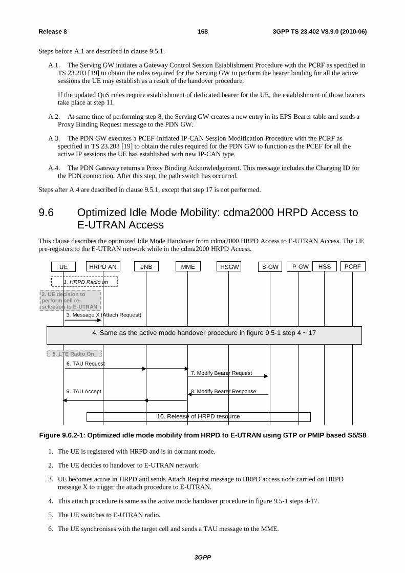
3GPP
3GPP TS 23.402 V8.9.0 (2010-06) 168Release 8
Steps before A.1 are described in clause 9.5.1.
A.1. The Serving GW initiates a Gateway Control Session Establishment Procedure with the PCRF as specified in TS 23.203 [19] to obtain the rules required for the Serving GW to perform the bearer binding for all the active sessions the UE may establish as a result of the handover procedure.
If the updated QoS rules require establishment of dedicated bearer for the UE, the establishment of those bearers take place at step 11.
A.2. At same time of performing step 8, the Serving GW creates a new entry in its EPS Bearer table and sends a Proxy Binding Request message to the PDN GW.
A.3. The PDN GW executes a PCEF-Initiated IP-CAN Session Modification Procedure with the PCRF as specified in TS 23.203 [19] to obtain the rules required for the PDN GW to function as the PCEF for all the active IP sessions the UE has established with new IP-CAN type.
A.4. The PDN Gateway returns a Proxy Binding Acknowledgement. This message includes the Charging ID for the PDN connection. After this step, the path switch has occurred.
Steps after A.4 are described in clause 9.5.1, except that step 17 is not performed.
9.6 Optimized Idle Mode Mobility: cdma2000 HRPD Access to E-UTRAN Access
This clause describes the optimized Idle Mode Handover from cdma2000 HRPD Access to E-UTRAN Access. The UE pre-registers to the E-UTRAN network while in the cdma2000 HRPD Access.
eNB S-GW HSGW HRPD AN P-GW
2. UE decision to perform cell re-selection to E-UTRAN
1. HRPD Radio on
HSS PCRF UE MME
3. Message X (Attach Request)
5. LTE Radio On
4. Same as the active mode handover procedure in figure 9.5-1 step 4 ~ 17
6. TAU Request
9. TAU Accept
10. Release of HRPD resource
7. Modify Bearer Request
8. Modify Bearer Response
Figure 9.6.2-1: Optimized idle mode mobility from HRPD to E-UTRAN using GTP or PMIP based S5/S8
1. The UE is registered with HRPD and is in dormant mode.
2. The UE decides to handover to E-UTRAN network.
3. UE becomes active in HRPD and sends Attach Request message to HRPD access node carried on HRPD message X to trigger the attach procedure to E-UTRAN.
4. This attach procedure is same as the active mode handover procedure in figure 9.5-1 steps 4-17.
5. The UE switches to E-UTRAN radio.
6. The UE synchronises with the target cell and sends a TAU message to the MME.

3GPP
3GPP TS 23.402 V8.9.0 (2010-06) 169Release 8
7. The MME sends a Modify Bearer Request message to the Serving GW. If the Serving GW receives any downlink data or it had already buffers any downlink data, it is now able to send the Downlink Data notification to MME to trigger paging procedure.
8. The Serving GW acknowledges a Modify Bearer Response to the MME.
9. The MME returns a TAU Accept message to the UE.
For connectivity to multiple PDNs the UE initiates re-establishment of the additional PDN connections using the UE requested PDN connectivity procedure described in clause 5.6.1.
10. HRPD resources are released as applicable and defined in 3GPP2 X.P0057 [51], using the PDN GW initiated release procedure as defined in clause 6.12.1 as a trigger.
9.7 S101 Tunnel Redirection Procedure S101 Tunnel Redirection Procedure is used when the UE perform TAU with MME change while the UE has already triggered a pre-registration procedure from LTE to the HRPD as described in clause 9.3.1 and the S101 session exists between the MME and the HRPD Access Network.
The detail procedure for the idle case is depicted as figure 9.7-1.
Figure 9.7-1: S101 tunnel redirection during TAU with MME change
1. UE performs pre-registration over the old MME while in ECM-CONNECTED state, followed by transition to ECM-IDLE state. The S101 tunnel exists between the old MME and the HRPD Access Network.
2. TAU procedure with MME change is executed as described in TS 23.401 [4], figure 5.3.3.1-1, up to the step where the new MME receives Update Location Ack from the HSS. The HRPD Access Network IP address is transferred to the new MME via the Context Response message.
3. The new MME sends Notification Request (Redirection, S101 Session ID) message to the HRPD Access Network. After receiving this message, the HRPD Access Network associates the S101 tunnel for this specific UE with the new MME. Then the HRPD Access Network releases any context associated with the old MME.
4. In response to the Notification Request message, the HRPD Access Network sends a Notification Response (S101 Session ID) message to the target MME.
5. The TAU procedure is completed.
The detailed procedure for the active case is depicted as figure 9.7-2.

3GPP
3GPP TS 23.402 V8.9.0 (2010-06) 170Release 8
Figure 9.7-2: S101 tunnel redirection during inter-eNodeB handover with MME relocation
1. UE performs pre-registration over the old MME while in ECM-CONNECTED state. The S101 tunnel exists between the old MME and the HRPD Access Network.
2. Inter-eNodeB handover with MME relocation procedure is executed as described in TS 23.401 [4], figure 5.5.1.2-1, steps up to TAU. The HRPD Access Network IP address is transferred to the new MME via the Forward Relocation Request message.
3. The new MME sends Notification Request (Redirection, S101 Session ID) message to the HRPD Access Network. After receiving this message, the HRPD Access Network associates the S101 tunnel with the new MME. Then the HRPD Access Network releases any context associated with the old MME.
4. In response to the Notification Request message, the HRPD Access Network sends a Notification Response (S101 Session ID) message to the target MME.
5. The TAU procedure occurs.
10 Handovers with Optimizations Between 3GPP Accesses and Mobile WiMAX
10.1 Optimizations for network-controlled dual radio handover
10.1.1 General Principles The solution for network-controlled dual radio handover between 3GPP accesses (GERAN, UTRAN, E-UTRAN) and Mobile WiMAX is based on the concepts of clause 4.1.2 In addition, the following principles apply when the ANDSF functionality is supported by the network and by the UE:
1) The EPS shall support mechanisms for delivery of inter-system mobility policies and access network discovery information over the S14 interface, as described in clause 4.8.
2) The inter-system mobility policies shall contain operator-defined rules and preferences that help the UE:
(i) determine when mobility between mobile WiMAX and 3GPP accesses is restricted or allowed; and
(ii) determine when a 3GPP or mobile WiMAX access is more preferable than the currently used radio access.
3) The access network discovery information shall contain information about mobile WiMAX access networks that are available in the vicinity of the UE, if the UE's location is known and if such information is available in the network and allowed by the operator.
4) If a UE discovers a neighbour mobile WiMAX access and determines (based on the inter-system mobility policies and user preferences) that:

3GPP
3GPP TS 23.402 V8.9.0 (2010-06) 171Release 8
(i) the discovered mobile WiMAX access is more preferable to the currently used 3GPP access; and
(ii) mobility from 3GPP access to mobile WiMAX access is allowed, then the UE shall attempt to handover to the discovered mobile WiMAX access;
according to the S2a/S2c procedures described in clause 8.
5) If a UE discovers one or more neighbour 3GPP accesses and determines (based on the inter-system mobility policies and user preferences) that:
(i) 3GPP access is more preferable to mobile WiMAX access; and
(ii) mobility from mobile WiMAX access to 3GPP access is allowed, then the UE shall select a neighbour 3GPP access (e.g. based on 3GPP access selection rules) and shall attempt to handover to the selected 3GPP access;
according to procedures described in clause 8.
11 Handover Optimizations Applicable to All Non-3GPP Accesses
<This clause describes handover optimization procedures that are generic and applicable to all non-3GPP accesses.>
12 Interactions Between HSS and AAA Server
12.0 General The interaction between the 3GPP AAA Server and the HSS is not explicitly presented in several figures of this specification. Though these entities are depicted as "AAA/HSS" in these figures, these functions are distinct and interact over the SWx reference point.
12.1 Location Management Procedures The location management procedures between HSS and 3GPP AAA Server is described in this clause.
Non-3GPP access location management procedures define the process in which the 3GPP AAA Server interacts with the HSS for the following purposes:
- To register the current 3GPP AAA Server address in the HSS for a given 3GPP user. This procedure is invoked by the 3GPP AAA Server after a new subscriber has been authenticated by the 3GPP AAA Server (either at attach and handover). As part of the response, the HSS returns the subscriber's user profile data (QoS profile, user capabilities, etc.) to the 3GPP AAA Server.
- To register the current PDN GW identity and its association with the UE and APN in the HSS for a given user. This information is provided by the AAA Server to the HSS at attachment to a particular PDN via non-3GPP access.
- To acquire the PDN GW identity for each of the already allocated PDN Gateway(s) with the corresponding PDN information from the HSS over the SWx reference point for a given UE. This is for the case when the UE has already been assigned PDN Gateway(s) due to a previous attach in a 3GPP access (when the UE is handed over from a 3GPP access to a non-3GPP access).
- To de-register the currently registered 3GPP AAA Server-address in the HSS for a given user and purge any related non-3GPP user status data in the HSS. The 3GPP AAA Server de-registers its address and purges user status data when e.g. the UE has disappeared from non-3GPP access coverage, when another EPC core network entity (e.g. charging system) has initiated a disconnection, when a re-authentication failure in the 3GPP AAA Server occurs, etc. If a UE has changed to a 3GPP access RAT, the 3GPP AAA Server initiated De-Registration procedure should not affect any currently selected PDN GW identity and APN associated with the UE's PDN Connection stored in the HSS and in use in the 3GPP access.

3GPP
3GPP TS 23.402 V8.9.0 (2010-06) 172Release 8
- HSS-initiated de-registration procedure to purge the UE from the 3GPP AAA server. This happens when the user's subscription has been cancelled or other operator-determined reasons. As a result, the 3GPP AAA server should deactivate any UE tunnel in the PDN GW and/or detach the UE from the access network.
The previous procedures are described in more detail in the following clauses. These procedures between the 3GPP AAA Server and the HSS are common to all non-3GPP accesses, whether trusted or non-trusted, and are independent of the mobility protocol used.
12.1.1 UE Registration Notification After a UE has successfully been authenticated and authorised by the 3GPP AAA Server to make use of a given non-3GPP access (over SWa/STa), ePDG (over SWm) or PDN GW (over S6b for S2c), the 3GPP AAA Server registers its address to the HSS, unless already done. In turn, the HSS should store the address of the registered 3GPP AAA server for the given user and mark the user as registered in the 3GPP AAA Server. In the response, the HSS returns user profile data.
3GPP AAA
Server HSS
1. UE Registration Request
2. UE Registration Ack
Figure 12.1.1-1: UE Registration Notification
1. Once the UE has been successfully authenticated by the 3GPP AAA server, the 3GPP AAA Server sends a UE Registration Request (User Identity, 3GPP AAA Server address) to the HSS.
2. The HSS checks that the user is known and that the stored 3GPP AAA Server address is the same one stored for the user and that it is the same 3GPP AAA Server that previously requested authentication vectors for this same user. If this is successful, the HSS marks the 3GPP AAA Server as the registered 3GPP AAA Server for user. The HSS responds with a UE Registration Ack (User Identity, Subscription Data). The subscription data includes information to be used by the PDN GW selection function or an already selected PDN GW identity and APN if present.
12.1.2 AAA-initiated UE De-registration Notification The 3GPP AAA Server requests the HSS to De-Register the currently registered UE. In doing so, the 3GPP AAA Server is notifying the HSS that the UE no longer has any context in the 3GPP AAA Server. The HSS should in turn delete the registered 3GPP AAA Server address.
3GPP AAA
Server HSS
1. UE De-Registration Request
2. UE De-Registration Ack
Figure 12.1.2-1: AAA-initiated UE De-registration Notification
1. The 3GPP AAA Server sends a UE De-Registration Request (User Identity, Cause) to the HSS. The "Cause" field may take values such as Authentication-Failure, UE-Detached, Charging-System-Request, etc.
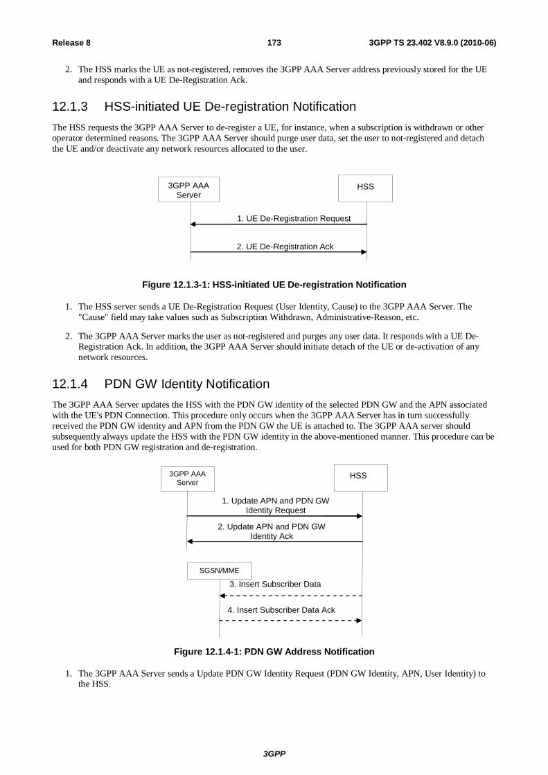
3GPP
3GPP TS 23.402 V8.9.0 (2010-06) 173Release 8
2. The HSS marks the UE as not-registered, removes the 3GPP AAA Server address previously stored for the UE and responds with a UE De-Registration Ack.
12.1.3 HSS-initiated UE De-registration Notification The HSS requests the 3GPP AAA Server to de-register a UE, for instance, when a subscription is withdrawn or other operator determined reasons. The 3GPP AAA Server should purge user data, set the user to not-registered and detach the UE and/or deactivate any network resources allocated to the user.
3GPP AAA
Server HSS
1. UE De-Registration Request
2. UE De-Registration Ack
Figure 12.1.3-1: HSS-initiated UE De-registration Notification
1. The HSS server sends a UE De-Registration Request (User Identity, Cause) to the 3GPP AAA Server. The "Cause" field may take values such as Subscription Withdrawn, Administrative-Reason, etc.
2. The 3GPP AAA Server marks the user as not-registered and purges any user data. It responds with a UE De-Registration Ack. In addition, the 3GPP AAA Server should initiate detach of the UE or de-activation of any network resources.
12.1.4 PDN GW Identity Notification The 3GPP AAA Server updates the HSS with the PDN GW identity of the selected PDN GW and the APN associated with the UE's PDN Connection. This procedure only occurs when the 3GPP AAA Server has in turn successfully received the PDN GW identity and APN from the PDN GW the UE is attached to. The 3GPP AAA server should subsequently always update the HSS with the PDN GW identity in the above-mentioned manner. This procedure can be used for both PDN GW registration and de-registration.
3GPP AAA Server
HSS
1. Update APN and PDN GW Identity Request
2. Update APN and PDN GW
Identity Ack
SGSN/MME
3. Insert Subscriber Data
4. Insert Subscriber Data Ack
Figure 12.1.4-1: PDN GW Address Notification
1. The 3GPP AAA Server sends a Update PDN GW Identity Request (PDN GW Identity, APN, User Identity) to the HSS.

3GPP
3GPP TS 23.402 V8.9.0 (2010-06) 174Release 8
The PDN GW identity is either the IP address (e.g., if the PDN GW has a single IP address for all the mobility protocols it supports or if it only supports one mobility protocol) or the FQDN (e.g. if the PDN GW has multiple IP addresses for the mobility protocols it supports).
2. The HSS checks that the user is known and that the stored 3GPP AAA Server name is the currently registered 3GPP AAA server for this same user. If this is successful, the HSS returns a Update PDN GW Identity Acknowledgement.
3. Steps 3-4 are only performed if the PDN GW identity information was successfully modified in the HSS and an SGSN or MME is registered in the HSS for the same UE. In this case the HSS sends an Insert Subscriber Data message to the SGSN or MME to update the change in the SGSN or MME. If both an SGSN and an MME is registered in the HSS, and Insert Subscriber Data message is sent to each of them.
4. The SGSN or MME acknowledges by sending an Insert Subscriber Data Ack message.
12.2 Subscriber Profile Management Procedures The subscriber profile management procedures between HSS and 3GPP AAA Server is described in this clause.
The procedure is invoked by the HSS when the subscriber profile has been modified and needs to be sent to the 3GPP AAA Server. This may happen due to a modification of user profile data in the HSS.
The 3GPP AAA Server may also request the user profile data from the HSS. This procedure is invoked when for some reason the subscription profile of a subscriber is lost or needs to be updated.
12.2.1 HSS-initiated User Profile Update Procedure The HSS may send a User Profile Update request to the 3GPP AAA Server whenever the subscriber profile in the HSS is modified since it was previously sent to the 3GPP AAA Server. The User Profile Update procedure is depicted in the following figure.
3GPP AAA
Server HSS
1. User Profile Update
2. User Profile Update Ack
Figure 12.2.1-1: HSS-initiated User Profile Update Procedure
1. The HSS sends a User Profile Update (User Identity, Subscription Data) message to the 3GPP AAA Server. If the HSS is aware of the non-3GPP access type it may return only the subscription data that affects the non-3GPP access.
2. The 3GPP AAA Server updates its subscription data and acknowledges the User Profile Update message by returning a User Profile Update Ack (User Identity) message. As a result, the 3GPP AAA Server may need to update the non-3GPP access network and the PDN GW with new authorisation data, the PDN GW with new service authorisation data and new subscribed QoS data.
12.2.2 AAA-initiated Provide User Profile Procedure The 3GPP AAA Server may send a Provide User Profile request to the HSS when the user subscription profile of a subscriber is lost or is corrupt or for any other reason.
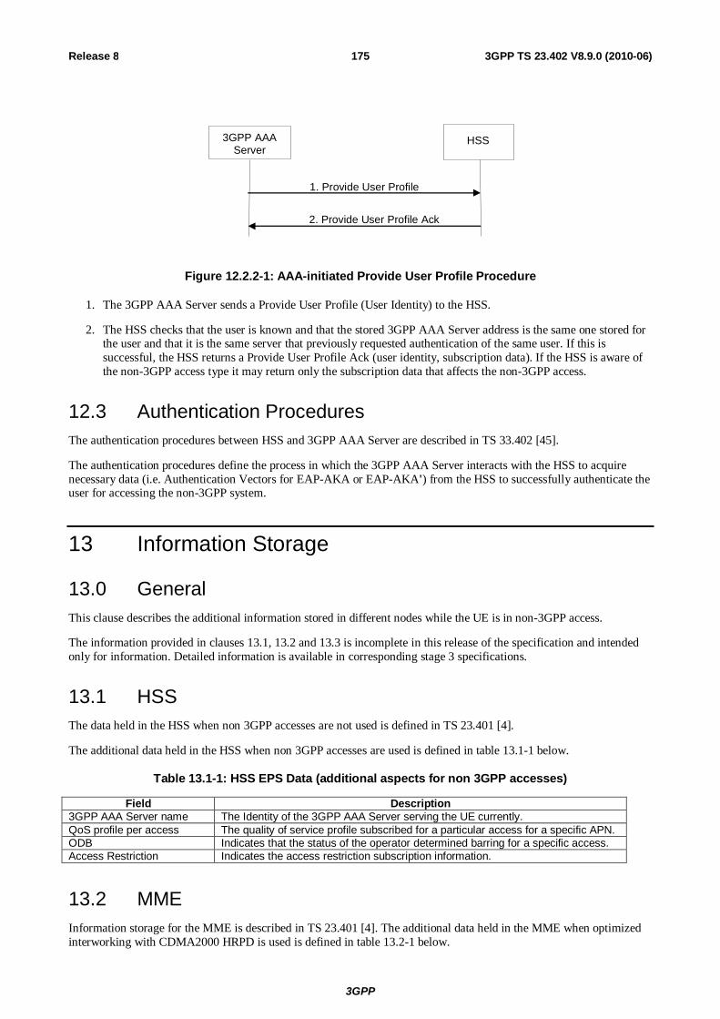
3GPP
3GPP TS 23.402 V8.9.0 (2010-06) 175Release 8
3GPP AAA Server
HSS
1. Provide User Profile
2. Provide User Profile Ack
Figure 12.2.2-1: AAA-initiated Provide User Profile Procedure
1. The 3GPP AAA Server sends a Provide User Profile (User Identity) to the HSS.
2. The HSS checks that the user is known and that the stored 3GPP AAA Server address is the same one stored for the user and that it is the same server that previously requested authentication of the same user. If this is successful, the HSS returns a Provide User Profile Ack (user identity, subscription data). If the HSS is aware of the non-3GPP access type it may return only the subscription data that affects the non-3GPP access.
12.3 Authentication Procedures The authentication procedures between HSS and 3GPP AAA Server are described in TS 33.402 [45].
The authentication procedures define the process in which the 3GPP AAA Server interacts with the HSS to acquire necessary data (i.e. Authentication Vectors for EAP-AKA or EAP-AKA') from the HSS to successfully authenticate the user for accessing the non-3GPP system.
13 Information Storage
13.0 General This clause describes the additional information stored in different nodes while the UE is in non-3GPP access.
The information provided in clauses 13.1, 13.2 and 13.3 is incomplete in this release of the specification and intended only for information. Detailed information is available in corresponding stage 3 specifications.
13.1 HSS The data held in the HSS when non 3GPP accesses are not used is defined in TS 23.401 [4].
The additional data held in the HSS when non 3GPP accesses are used is defined in table 13.1-1 below.
Table 13.1-1: HSS EPS Data (additional aspects for non 3GPP accesses)
13.2 MME Information storage for the MME is described in TS 23.401 [4]. The additional data held in the MME when optimized interworking with CDMA2000 HRPD is used is defined in table 13.2-1 below.
Field Description 3GPP AAA Server name The Identity of the 3GPP AAA Server serving the UE currently. QoS profile per access The quality of service profile subscribed for a particular access for a specific APN. ODB Indicates that the status of the operator determined barring for a specific access. Access Restriction Indicates the access restriction subscription information.

3GPP
3GPP TS 23.402 V8.9.0 (2010-06) 176Release 8
Table 13.2-1: MME storage requirements to support optimized interworking with CDMA2000 HRPD
Field Description S101 HRPD Access Network IP address
The IP address of the HRPD AN used for the S101 tunnel for a UE. This is stored on a per UE basis.
S103 Forwarding Address HS GW IP address used for data forwarding to the HRPD access over S103 interface. This is stored on a per UE basis.
S103 GRE key(s) GRE Key(s) used for the data forwarding tunnel to the HS GW - one per UE-PDN connection. This is stored on a per UE basis.
13.3 S-GW Information storage for the S-GW is described in TS 23.401 [4]. The additional data held in the S-GW when optimized interworking with CDMA2000 HRPD is used is defined in table 13.3-1 below.
Table 13.3-1: S-GW storage requirements to support optimized interworking with CDMA2000 HRPD
Field Description S103 Forwarding Address HS-GW IP address used for data forwarding to the HRPD access
over S103 interface. This is stored on a per UE basis. S103 GRE key(s) GRE Key(s) used for the data forwarding tunnel to the HS-GW -
one per UE-PDN connection. This is stored on a per UE basis.
13.4 Handling of Wild Card APN When the wild card APN is present in the subscription context, the UE is authorized to connect to APNs which are not present in the subscription context.
When a request is received for registering a PDN GW ID for such an active APN which is not present in the subscription context, the nodes (HSS/MME/ S4 SGSN/AAA Server/Non-3GPP access) shall store the PDN GW ID and the APN for the UE.
When a request is received for deregistering of PDN GW ID, for such an active APN which is not present in the subscription context, the nodes (HSS/MME/ S4 SGSN/AAA Server/Non-3GPP access) shall delete the PDN GW ID and the APN for the UE.
14 Void
15 Functional Description and Procedures for 3GPP Accesses with S2c
15.1 S2c Bootstrapping via DSMIPv6 Home Link When connected over the UE home link (i.e. 3GPP access as defined in clause 4.1), the UE may trigger the establishment of S2c IKEv2 SA, e.g. to optimize future handovers to non-3GPP accesses using S2c. For each PDN connection, the S2c IKEv2 SA establishment has to be performed separately.

3GPP
3GPP TS 23.402 V8.9.0 (2010-06) 177Release 8
UE P DNGW 3GPP AAA/HSS
1. PDNGW discovery
2. IKEv2 Security Association establishment & IPv6 HoA allocation 2. Auth. & Authorization
3GPP AAA Proxy
0. 3GPP PDN Access Attach
3 . Home Link Detection
Figure 15.1-1: S2c PDN Attach via DSMIPv6 home link
0. In this procedure it is assumed that UE is already attached to the PDN over the 3GPP access system as defined in TS 23.401 [4]. This step, according to TS 23.401 [4] could be an initial attach to a default PDN or a UE initiated subsequent attach to another PDN.
1. The UE discovers the PDN GW providing access to the PDN it connected to in Step 0, as defined in the clause 4.5.2. To ensure reachability of the PDN GW, signalling associated with this step as well as step 2 below, should be performed over the connection established by step 0 above.
2. A security association is established between the UE and PDN GW to secure the DSMIPv6 messages related to this PDN connection between the UE and the PDN GW.
The UE initiates the establishment of the security association using IKEv2 [9]; EAP [11] is used over IKEv2 for authentication purposes. The PDN GW communicates with the AAA infrastructure in order to complete the authentication.
During this step an IPv6 home prefix is assigned by the PDN GW to the UE as defined in RFC 4877 [22]. During this step the UE shall include the IPv6 Home Address and may include the APN of the PDN it wants to access. The PDN GW address and APN associated with the UE's PDN Connectivity are registered by the AAA server with the HSS as described in clause 12.
In this step, the PDN GW may be either in the HPLMN or in the VPLMN. When the PDN GW is in the VPLMN, the interaction between the PDN GW in the VPLMN with the AAA/HSS in the HPLMN may involve a 3GPP AAA Proxy in the VPLMN as specified in TS 23.234 [5].
3. UE confirms that it is located in its DSMIPv6 home link for the given PDN, as described for DSMIPv6 Home Link Detection Function in clause 4.5.6.
In some cases this procedure may result in a PDN GW that is different than the one the UE is connected to in step 0. In this case the PDN GW reallocation procedure defined in clause 6.10 is applied.

3GPP
3GPP TS 23.402 V8.9.0 (2010-06) 178Release 8
Annex A (informative): GTP - PMIP Roaming The scenarios below identify and describe various deployment scenarios for interworking between EPC networks based on GTP and EPC networks based on PMIP. The scenario described here are the direct peering scenario and the proxy-based interworking.
A.1 Direct Peering Scenario The "direct peering" scenario consists in having one of the two roaming partners provide support for both variants of roaming flavour (e.g. a PMIP operator would support GTP-based roaming interface towards a GTP-only roaming partner, or vice versa) in order to make roaming possible.
The support for such roaming flavour can be provided either on the same GW node or on different GW nodes. Upon establishment of connectivity for a specific roaming UE, the Visited network chooses a GTP-based or a PMIP-based S8 interface (on the same GW node or on different GW nodes, note that for a single user only a single Serving GW is allocated when connecting to EPC), depending on the preferences of the roaming partner that owns the subscriber.
Serving GW
(PMIP)
vPCRF
Gxc
GTP – HPLMN PMIP – VPLMN
PMIP GTP
S9
Serving GW
(GTP)
Towards other PMIP
operators
PDN GW (GTP)
PCRF
Gx
GTP
Towards other PMIP
operators
GTP – VPLMN
Serving GW
(GTP)
a) PMIP VPLMN – GTP HPLMN
b) GTP VPLMN – PMIP HPLMN
PDN GW (PMIP)
hPCRF
Gx
PMIP – HPLMN
PMIP
S9
PDN GW (GTP)
Gx
Figure A.1-1: Direct peering examples: a) PMIP-based VPLMN to GTP-based HPLMN; b) GTP-based VPLMN to PMIP-based HPLMN
Depicted in Figure A.1-1 (a) is an example of "direct peering" interworking between a GTP-based HPLMN and a PMIP-based VPLMN. When roamers whose subscription is owned by the GTP-based operator attach to the EPS network of the PMIP-based operator, they are assigned a GTP-capable GW acting in the role of S-GW. The S-GW selection is carried out by MME or SGSN based on the subscriber's HPLMN. In case of the Serving GW supporting

3GPP
3GPP TS 23.402 V8.9.0 (2010-06) 179Release 8
both GTP and PMIP, the MME/SGSN should indicate the Serving GW which protocol should be used over S5/S8 interface.
Depicted in Figure A.1-1 (b) is an example of "direct peering" interworking between a PMIP-based HPLMN and a GTP-based VPLMN. When roamers whose subscription is owned by the PMIP-based operator attach to the EPS network of the GTP-based operator, they are assigned a GTP-capable S-GW. The information provided by the PMIP-based HPLMN for the P-GW selection function must take into account that the Visited network is GTP-only, in order to return either the IP address (or an APN that can be resolved to an IP address according to the PDN GW resolution mechanism) that points to a GTP-capable PDN GW.
Figure A.1-2 depicts the scenario in which a UE from a GTP-based network roams in a PMIP-based network, local breakout is used, and home-routed bearers are also possible. As with the home-routed case, the MME or SGSN in the PMIP-based VPLMN selects a GTP-capable Serving GW, but it selects a PMIP capable PDN GW. As a result, the S-GW in this example supports both GTP and PMIP based S5/S8. This allows the local breakout bearer and any associated home-routed bearer for the user (e.g. the default bearer) to be served by the same Serving GW. Support of S9 may not be required in all local breakout scenarios.
Serving GW
(PMIP)
Serving GW
(PMIP, GTP)
PDN GW
(PMIP)
vPCRF
PMIP
hPCRF
Gx
S9
PMIP – VPLMN GTP – HPLMN
Gxc
Figure A.1-2: Direct peering example: Local Breakout, UE from GTP HPLMN Roaming in PMIP VPLMN
Figure A.1-3 depicts the scenario in which a UE from a PMIP-based network roams into a GTP-based network and local breakout is used. As with the home-routed case, the MME/SGSN in the GTP-based VPLMN selects a GTP-capable Serving GW and the PDN GW selection function selects a GTP-capable PDN GW. This allows the local breakout bearer and any associated home-routed bearer for the user (e.g., the default bearer) to be served by the same Serving GW. Support of S9 may not be required in all local breakout scenarios.

3GPP
3GPP TS 23.402 V8.9.0 (2010-06) 180Release 8
Serving GW
(GTP)
Serving GW
(GTP) PDN GW
(GTP)
vPCRF
GTP
hPCRF
Gx
S9
GTP – VPLMN PMIP – HPLMN
Figure A.1-3: Direct peering example: Local Breakout, UE from PMIP HPLMN Roaming in GTP VPLMN
A.2 Proxy-based interworking In this scenario an Interworking Proxy (IWP) sits between the GTP-based PLMN and the PMIP-based PLMN to perform protocol conversion between the GTP protocol on one side and the PMIP and Diameter protocols on the other side.
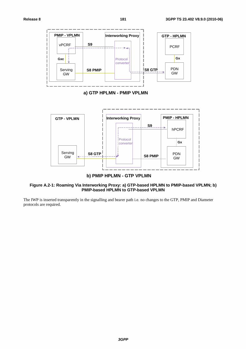
3GPP
3GPP TS 23.402 V8.9.0 (2010-06) 181Release 8
Serving GW
vPCRF
Gxc
GTP - HPLMN PMIP - VPLMN
S8 PMIP S8 GTP
S9
Interworking Proxy
PDN GW
PCRF
Gx Protocol converter
a) GTP HPLMN - PMIP VPLMN
Protocol converter
GTP - VPLMN Interworking Proxy PMIP - HPLMN
b) PMIP HPLMN - GTP VPLMN
Serving GW
S8 GTP S8 PMIP
S9
PDN GW
hPCRF
Gx
Figure A.2-1: Roaming Via Interworking Proxy: a) GTP-based HPLMN to PMIP-based VPLMN; b) PMIP-based HPLMN to GTP-based VPLMN
The IWP is inserted transparently in the signalling and bearer path i.e. no changes to the GTP, PMIP and Diameter protocols are required.

3GPP
3GPP TS 23.402 V8.9.0 (2010-06) 182Release 8
Annex B (informative): Guidance for Contributors to this Specification The following guidance is provided for drafting figures for TS 23.402 that share some common procedures with TS 23.401 [4].
Representation of PMIP or GTP variants of S5/S8:
- Flows to TS 23.401 [4] will contain the complete procedures for GTP-based S5/S8.
- In TS 23.401 [4], clause(s) of a flow that is different for PMIP version of S5/S8 interface are shown surrounded by shaded box indexed by capital letter in ascending order, e.g. "A", "B", "C", etc.
At the bottom of the flow, the following text should be included, e.g.
NOTE: Procedure steps (A) and (B) for an PMIP-based S5/S8 are defined in TS 23.402.
- In TS 23.402, each step for the relevant clause, belonging to say annex A, of the flow should be indicated by "A.1, A.2, …" . In TS 23.402 common clauses of the flow captured in TS 23.401 [4], should be indicated by shaded boxes with text, e.g. "Procedures in TS 23.401, Figure x.y.z-k, before A", "Procedures in TS 23.401, Figure x.y.z-k, between A and B", etc.
For an illustrative example of the drafting guidelines rule, please refer to Figure 5.4.1-1 in TS 23.401 [4] and corresponding Figure 5.4.1-1-1 in this specification.
Representation of different architectural cases:
- For each case supported, indicate the presence of the optional network entities that may be included in the procedure step. These optional entities appear between the source and destination of the procedure interaction arc as a gray circle. For example, a vPCRF may stand between the Serving GW and the hPCRF.
- In text following a procedure diagram, list the different cases supported by the figure.
- For each case that is supported, indicated what the role of the optional network entity is, when it occurs in the interaction. For example, "In the roaming case, the vPCRF forwards messages between the Serving GW and the PDN GW".
While it is possible to describe these interactions in each step in which they might occur, this will tend to clutter and complicate the procedure diagrams and should be avoided. A single paragraph found beneath each procedure including optional network elements should suffice to clarify that procedure.
Representation of the impact of multiple PDN connectivity:
- In text following a procedure diagram, list the specific impacts arising from multiple PDN connectivity. This will chiefly include a description of which interactions in the figure may be repeated N times for each PDN connected to.

3GPP
3GPP TS 23.402 V8.9.0 (2010-06) 183Release 8
Annex C (informative): Handover Flows Between Non-3GPP Accesses
C.1 General This clause describes non-exhaustive examples of flows for handover between non-3GPP accesses connected to the EPC. The handover scenarios are based on the mechanisms defined in clause 8 of this document.
C.2 Trusted Non-3GPP IP Access to Trusted Non-3GPP IP Access with DSMIPv6 over S2c Handover
In this scenario, the session starts in (source) trusted non3GPP access using DSMIPv6 over S2c. The session hands over to another (target) trusted non-3GPP access system. The UE subsequently initiates DSMIPv6 with the same PDN GW to maintain the IP session.
In the non-roaming case, none of the optional entities in Figure C.2-1 are involved.
2. The process continues as defined by steps marked as (A) in 8.4.2-1
4. Release resources in Source Trusted Non-3GPP IP Access
PDN GW
AAA Proxy
vPCRF hPCRF UE
Roaming Scenario
HSS/ AAA
Source Trusted Non-3GPP IP Access
Target Trusted Non-3GPP IP Access
1. DSMIPv6 Tunnel
3. DSMIPv6 Tunnel
Figure C.2-1: Trusted non-3GPP to Trusted non-3GPP handover based on S2c
1. The UE uses a source Trusted non-3GPP IP access system. It has a local IP address from the non-3GPP system which is used as a care-of address in the DSMIPv6 registration to the PDN GW. The UE maintains a security association with the PDN GW.
2. The UE decides to initiate an access procedure with a new, target Trusted non-3GPP IP access. The procedure continues with the steps defined in Figure 8.6-1 (A)
3. The UE continues the ongoing session(s) via the same PDN GW maintaining the same IP address.
4. Resources in the source Trusted Non-3GPP IP access are released.
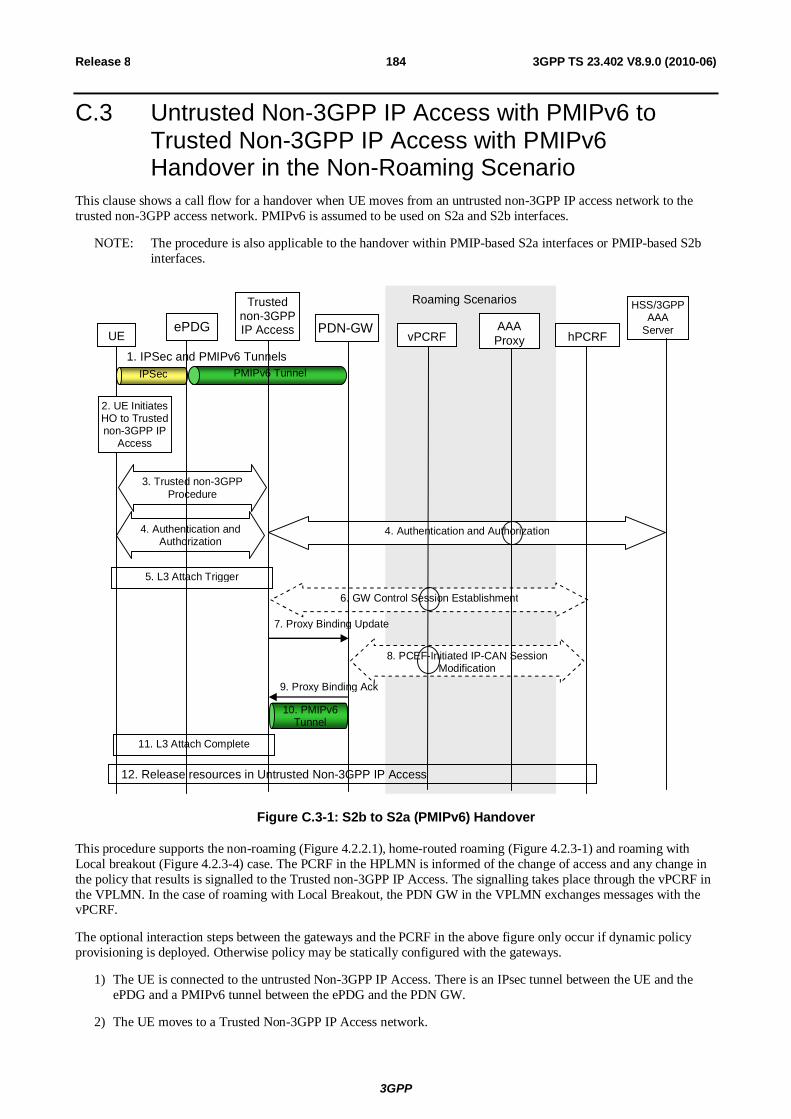
3GPP
3GPP TS 23.402 V8.9.0 (2010-06) 184Release 8
C.3 Untrusted Non-3GPP IP Access with PMIPv6 to Trusted Non-3GPP IP Access with PMIPv6 Handover in the Non-Roaming Scenario
This clause shows a call flow for a handover when UE moves from an untrusted non-3GPP IP access network to the trusted non-3GPP access network. PMIPv6 is assumed to be used on S2a and S2b interfaces.
NOTE: The procedure is also applicable to the handover within PMIP-based S2a interfaces or PMIP-based S2b interfaces.
3. Trusted non-3GPP Procedure
4. Authentication and Authorization
4. Authentication and Authorization
5. L3 Attach Trigger
7. Proxy Binding Update
9. Proxy Binding Ack
10. PMIPv6 Tunnel
11. L3 Attach Complete
6. GW Control Session Establishment
8. PCEF-Initiated IP-CAN Session Modification
PMIPv6 Tunnel IPSec
HSS/3GPP AAA
Server
12. Release resources in Untrusted Non-3GPP IP Access
2. UE Initiates HO to Trusted non-3GPP IP
Access
1. IPSec and PMIPv6 Tunnels
Roaming Scenarios
UE PDN-GW vPCRF
AAA Proxy hPCRF
ePDG
Trusted non-3GPP IP Access
Figure C.3-1: S2b to S2a (PMIPv6) Handover
This procedure supports the non-roaming (Figure 4.2.2.1), home-routed roaming (Figure 4.2.3-1) and roaming with Local breakout (Figure 4.2.3-4) case. The PCRF in the HPLMN is informed of the change of access and any change in the policy that results is signalled to the Trusted non-3GPP IP Access. The signalling takes place through the vPCRF in the VPLMN. In the case of roaming with Local Breakout, the PDN GW in the VPLMN exchanges messages with the vPCRF.
The optional interaction steps between the gateways and the PCRF in the above figure only occur if dynamic policy provisioning is deployed. Otherwise policy may be statically configured with the gateways.
1) The UE is connected to the untrusted Non-3GPP IP Access. There is an IPsec tunnel between the UE and the ePDG and a PMIPv6 tunnel between the ePDG and the PDN GW.
2) The UE moves to a Trusted Non-3GPP IP Access network.
3GPP
3GPP TS 23.402 V8.9.0 (2010-06) 185Release 8
3) The access specific procedures of the Trusted Non-3GPP IP Access are performed. These procedures are outside of the scope of 3GPP.
4) The EAP authentication procedure is initiated and performed involving the UE, Trusted Non-3GPP IP Access and the 3GPP AAA Server. In the roaming case, there may be several AAA proxies involved. As part of the authentication procedure, the information of the selected PDN GW, e.g. PDN GW's address, is conveyed to the MAG in the Trusted Non-3GPP IP Accesses.
5) After successful authentication and authorization, the L3 attach procedure is triggered.
6) The Trusted non-3GPP IP access initiates a Gateway Control Session Establishment Procedure with the PCRF as specified in TS 23.203 [19] to obtain the rules required for the Trusted non-3GPP IP access to perform the bearer binding.
7) The MAG function in the Trusted Non-3GPP IP Access sends Proxy Binding Update message to the PDN GW.
8) The PDN GW executes a PCEF-Initiated IP CAN Session Modification Procedure with the PCRF as specified in TS 23.203 [19] to inform the PCRF of the new IP-CAN type and obtain the updates to the PCC rules.
9) The PDN GW processes the proxy binding update and creates a binding cache entry for the UE. The PDN GW allocates IP address for the UE. The PDN GW then sends a Proxy Binding Acknowledgement to the MAG function in the Trusted Non-3GPP IP Access, including the IP address(s) allocated for the UE. The IP address allocated is same as that was assigned to UE before over the Untrusted Non-3GPP Accesses.
10) The PMIPv6 tunnel is set up between the Trusted Non-3GPP IP Access and the PDN GW.
11) L3 attach procedure is completed. IP connectivity between the UE and the PDN GW is set up for uplink and downlink direction over the trusted non-3GPP IP access.
12) The PDN GW initiates resource allocation deactivation procedure in the untrusted non-3GPP IP access as defined in clause 6.12 or clause 7.9.
C.4 Trusted/Untrusted Non-3GPP IP Access with DSMIPv6 to Trusted Non-3GPP IP Access with PMIPv6 Handover in the Non-Roaming Scenario
This clause shows a call flow for a handover when UE moves from a source trusted/untrusted non-3GPP IP access network to a target trusted non-3GPP access network. PMIPv6 is assumed to be used on S2a and DSMIPv6 is assumed to be used on source trusted/untrusted access network.

3GPP
3GPP TS 23.402 V8.9.0 (2010-06) 186Release 8
1a. IPSec Tunnel 1. DSMIPv6 Tunnel
Source Trusted Non-3GPP IP Access or ePDG
Trusted Non-3GPP Access
HSS/3GPP AAA
Server
hPCRF AAA Proxy
vPCRF PDN GW UE
Roaming Scenario
5. Trusted Non-3GPP IP Attach as defined in Steps 5-8 of Figure 8.2.2-1
9. BU (DSMIPv6 deregistration with lifetime=0), BA
8. UE-initiated Connectivity to additional PDNs
2. UE discovers Trusted Non-3GPP Access and initiates
HO
3. Access Authentication 3. Authentication and Authorization (PDN GW)
6. L3 Attach Completion 7. PMIPv6 tunnel
10. PCRF initiated Gateway Control Session Termination Procedure
4. L3 Attach Trigger
Figure C.4-1: S2c over trusted or untrusted Non-3GPP IP access to S2a (PMIPv6) Handover
This procedure supports the non-roaming (Figure 4.2.2.1), home routed roaming (Figure 4.2.3-1) and roaming with Local breakout (Figure 4.2.3-4) case. The PCRF in the HPLMN is informed of the change of access and any change in the policy that results is signalled to the Trusted non-3GPP IP Access. The signalling takes place through the vPCRF in the VPLMN. In the case of roaming with Local Breakout, the PDN GW in the VPLMN exchanges messages with the vPCRF.
The optional interaction steps between the gateways and the PCRF in the above figure only occur if dynamic policy provisioning is deployed. Otherwise policy may be statically configured with the gateways.
In case of connectivity to multiple PDNs, step 8 is repeated for each PDN the UE is connected to. This step can occur in parallel for each PDN. Other impacts related to the handover for multiple PDNs are described in clause 8.1. Alternatively, if supported by non-3GPP access technology and if the UE does not provide any APN upon handover attach in the trusted non-3GPP IP access, Step 5 is repeated for each PDN the UE is connected to, instead of Step 8. DSMIPv6 de-registration in step 9 will be performed for each PDN connection. These steps can occur in parallel for each PDN.
1. The UE is connected to the trusted/untrusted Non-3GPP Access using S2c.
1a. There is an IPsec tunnel between the UE and the ePDG if UE is connected over untrusted access network.
2. The UE moves to a Trusted Non-3GPP Access network.
3. The EAP authentication procedure is initiated and performed involving the UE, Trusted Non-3GPP IP Access and the 3GPP AAA Server. In the roaming case, there may be several AAA proxies involved. As part of the authentication procedure, the information of the selected PDN GW, e.g. PDN GW's address, is conveyed to the MAG in the Trusted Non-3GPP IP Accesses. The PDNs the UE is connected to are obtained from the HSS with the UE subscriber profile.

3GPP
3GPP TS 23.402 V8.9.0 (2010-06) 187Release 8
4. After successful authentication and authorization, the L3 attach procedure is triggered.
5. The UE continues the attach to the Trusted Non-3GPP IP Access as defined in Steps 5-8 of Figure 8.2.2-1, except that the IP CAN session modification defined in step 7 is triggered as explained below.
6. L3 attach procedure is completed. IP connectivity between the UE and the PDN GW is set for uplink and downlink direction over the trusted non-3GPP IP access.
7. The PMIPv6 tunnel is set up between the Trusted Non-3GPP IP Access and the PDN GW. The UE can send/receive IP packets at this point.
8. In case of connectivity to multiple PDNs, the UE establishes connectivity to all the PDNs besides the Default PDN that the UE was connected to before the handover as described in clause 6.8.1.
9. The UE sends a BU (lifetime) to the PDN GW to de-register its DSMIPv6 binding that was created while the UE was in non-3GPP access system. The PDN GW responds with a BA message.
Any time after step 5, prior to receiving the de-registration Binding Update from the UE, the PDN GW may de-register the DSMIPv6 binding. In this case the PDN GW shall send a Binding Revocation Indication message to the UE.
Following the de-registration of the DSMIPv6 binding due to reception of de-registration Binding update or due to triggering Binding Revocation, the PDN GW triggers PCEF initiated IP CAN session modification, instead of doing it as part of the step 5.
10. The PCRF initiates "PCRF-initiated Gateway Control Session Termination" procedure to release the resources in the non-3GPP access. This procedure is triggered by the PCEF-Initiated IP-CAN Session Modification Procedure with the PCRF.
C.5 Handover Between Two Untrusted Non-3GPP IP Accesses Connected to the Same ePDG
This handover case is handled by MOBIKE [18], i.e. the existing IPSec tunnel, via the first untrusted non-3GPP IP access, is only modified for the use with the second untrusted non-3GPP access (and not torn down and re-created from scratch). It is assumed that the MOBIKE support indication has been sent by UE to ePDG in the initial attach.
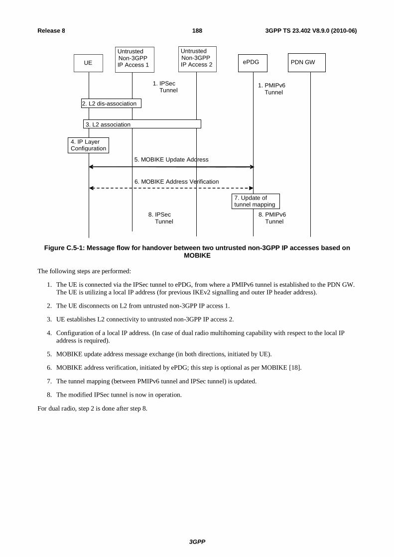
3GPP
3GPP TS 23.402 V8.9.0 (2010-06) 188Release 8
UE ePDG PDN GW
7. Update of tunnel mapping
2. L2 dis-association
3. L2 association
Untrusted Non-3GPP IP Access 1
1. PMIPv6 Tunnel
Untrusted Non-3GPP IP Access 2
4. IP Layer Configuration
6. MOBIKE Address Verification
5. MOBIKE Update Address
1. IPSec Tunnel
8. IPSec Tunnel
8. PMIPv6 Tunnel
Figure C.5-1: Message flow for handover between two untrusted non-3GPP IP accesses based on MOBIKE
The following steps are performed:
1. The UE is connected via the IPSec tunnel to ePDG, from where a PMIPv6 tunnel is established to the PDN GW. The UE is utilizing a local IP address (for previous IKEv2 signalling and outer IP header address).
2. The UE disconnects on L2 from untrusted non-3GPP IP access 1.
3. UE establishes L2 connectivity to untrusted non-3GPP IP access 2.
4. Configuration of a local IP address. (In case of dual radio multihoming capability with respect to the local IP address is required).
5. MOBIKE update address message exchange (in both directions, initiated by UE).
6. MOBIKE address verification, initiated by ePDG; this step is optional as per MOBIKE [18].
7. The tunnel mapping (between PMIPv6 tunnel and IPSec tunnel) is updated.
8. The modified IPSec tunnel is now in operation.
For dual radio, step 2 is done after step 8.

3GPP
3GPP TS 23.402 V8.9.0 (2010-06) 189Release 8
Annex D: Void

3GPP
3GPP TS 23.402 V8.9.0 (2010-06) 190Release 8
Annex E (Informative): Gateway Relocation in the Trusted Non-3GPP IP Access Gateway relocation within the Trusted Non-3GPP IP Access is possible using the procedures defined in this clause. The trigger for gateway relocation and any mechanisms for preserving or transferring context between gateways within the Trusted Non-3GPP IP Access is considered out of scope of this specification and should be handled within standards external to 3GPP.
In both the case of PMIPv6 and MIP v4 FACoA on S2a, the Gateway Control Session for the target gateway of the relocation is established before the intra-non-3GPP handover occurs. After the handover, the Gateway Control Session in the source gateway of the handover is terminated.
The mobility management and policy control signalling are both shown as optional messages. This is to allow flexibility depending on the requirements of the trusted non-3GPP IP access system. This allows a policy control signalling relocation (on Gxa) or a relocation of the local mobility anchor (S2a) or both (Gxa and S2a).
E.1 Gateway Relocation with PMIPv6 on S2a
UE PDN GW 3GPP AAA Proxy
Trusted non - 3GPP IP Access vPCRF hPCRF HSS/AA
A 1. Non - 3GPP Specific Trigger
Roaming Scenarios
4. Proxy Binding Update 5. Proxy Binding Ack
7. Gateway Control Session Termination
8. Ack Gateway Control Session Termination
2. Gateway Control Session Establishment
3. Acknowledge Gateway Control Session Establishment
6. PMIPv6 Tunnel Established
Figure E.1-1: Gateway Relocation when PMIPv6 MM mechanism is used over S2a
When the Gateway Relocation procedure occurs in the Non-Roaming case (Figure 4.2.2-1), the vPCRF is not involved.
In the case of Roaming (Figure 4.2.3-1) and Local Breakout (Figure 4.2.3-4), the vPCRF is employed to forward messages from the hPCRF in the home PLMN, by way of the vPCRF in the VPLMN to the non-3GPP access.
1) A gateway relocation is triggered, to be initiated by the Trusted Non-3GPP IP Access. These trigger is outside the scope of 3GPP standardization.
2) The target Gateway in the Trusted Non-3GPP IP Access sends a Gateway Control Session Establishment message to the hPCRF.

3GPP
3GPP TS 23.402 V8.9.0 (2010-06) 191Release 8
3) The PCRF responds to the target Gateway an Ack Gateway Control Session Establishment (QoS Rules, Event Triggers) message. The PCC rules provide the PDN GW with information required to enforce the dedicated bearer policy. The event triggers indicate to the PDN GW when to report an event back to the PCRF related to the dedicated bearer.
4) The target Gateway sends a Proxy Binding Update (MN NAI) message to the PDN GW to register the UE at the PDN-GW. The MN NAI identifies the UE.
5) After creating the binding cache entry for the UE, the PDN GW responds with a Proxy Binding Acknowledgement (MN NAI, Lifetime, UE Address Info) message to the MAG. The MN NAI repeats the UE identity sent previously. The Lifetime expresses the duration of validity of the binding. The UE Address info includes the allocated IP Address(es) corresponding to the IP CAN session.
6) The PMIP tunnel from the target gateway to the PDN GW is established.
7) The source Gateway in the Trusted Non-3GPP IP Access system sends a Gateway Control Session Termination to the PCRF. This gateway ceases to perform Bearer Binding and associated policy controlled functions.
8) The PCRF sends an Acknowledge Gateway Control Session Termination message to the Trusted Non-3GPP IP Access acknowledging the termination of the control session.
E.2 Gateway Relocation with MIPv4 FACoA on S2a
UE PDN GW 3GPP AAA Proxy
Trusted non - 3GPP IP Access vPCRF hPCRF HSS/AA
A 1. Non - 3GPP Specifi c Trigger
Roaming Scenari os
2 . MIPv4 Registration Request [UE ID = NAI, reverse tunnel request
4 . MIPv4 Registration Request [UE ID = NAI, reverse tunnel request ]
5. MIPv4 Registration Reply (home address)
7. MIPv4 Registration Reply (home address)
8. MIP Tunnel Established
3. Gateway Control Session Establishment
Procedure
6. Gateway Control Session Termination Procedure
Figure E.2-1: Gateway Relocation when MIPv4 FACoA mode MM mechanism is used over S2a
When the Gateway Relocation procedure occurs in the Non-Roaming case (Figure 4.2.2-1), the vPCRF is not involved.
In the case of Roaming (Figure 4.2.3-1) and Local Breakout (Figure 4.2.3-4), the vPCRF is employed to forward messages from the hPCRF in the home PLMN, by way of the vPCRF in the VPLMN to the non-3GPP access.

3GPP
3GPP TS 23.402 V8.9.0 (2010-06) 192Release 8
1) A gateway relocation is triggered, to be initiated by the UE. This trigger is outside the scope of 3GPP standardization.
2) The UE sends a Registration Request (RRQ) RFC 3344 [12] message to the FA. Reverse Tunnelling shall be requested. This ensures that all traffic will go through the PDN GW. The RRQ message shall include the NAI-Extension RFC 3775 [14] and the Home Agent Address.
3) The Trusted non-3GPP access initiates the Gateway Control Session Establishment Procedure with the PCRF, as specified in TS 23.203 [19]. The Trusted non-3GPP access provides the information to the PCRF to correctly associate it with the IP CAN session to be established in Step 9 and also to convey subscription related parameters to the PCRF.
4) The FA processes the message according to RFC 3344 [12] and forwards a corresponding RRQ message to the PDN GW.
5) The PDN GW allocates an IP address for the UE and sends a Registration Reply (RRP) RFC 3344 [12] to the FA, including the IP address allocated for the UE.
6) The Trusted Non-3GPP Access Network initiates the Gateway Control Session Termination Procedure with the PCRF as specified in TS 23.203 [19]. The Trusted Non-3GPP Access Network no longer applies QoS policy to service data flows for this UE.
7) The FA processes the RRP according to RFC 3344 [12] and sends a corresponding RRP message to the UE.
8) IP connectivity from the UE to the PDN GW is now setup. A MIP tunnel is established between the FA in the Trusted Non-3GPP IP Access and the PDN GW.

3GPP
3GPP TS 23.402 V8.9.0 (2010-06) 193Release 8
Annex F (informative): Change history
Change history Date TSG # TSG Doc. CR Rev Cat Subject/Comment Old New
2007-12 SP-38 SP-070829 - - - MCC editorial update for presentation to TSG SA for approval 1.5.1 2.0.0 2007-12 SP-38 - - - - Release 8 Version created after approval at TSG SA #38 2.0.0 8.0.0 2008-03 SP-39 SP-080123 0158 - C Attach Type for 3GPP accesses and Incorporation of MIPv4 into
Non-3GPP-to-EUTRAN Handover 8.0.0 8.1.0
2008-03 SP-39 SP-080125 0157 1 F Reference points renaming 8.0.0 8.1.0 2008-03 SP-39 SP-080123 0156 1 C Informing the PCRF about existence of tunnelled traffic 8.0.0 8.1.0 2008-03 SP-39 SP-080123 0154 - C IEs for Non-3GPP Detach & Additional PDN Procedures and
Updates for currently valid version of PMIPv6 draft 8.0.0 8.1.0
2008-03 SP-39 SP-080123 0153 - C Cleanup/Merge of CR0063R1: Clean-up and addition of IEs for consistency
8.0.0 8.1.0
2008-03 SP-39 SP-080125 0151 - F Merger of 23.402 CR0066R3 (MIPv4 FA CoA procedures for non-3GPP access to SAE) and 23.402 CR0074R2 (Editorial corrections for TS 23.402)
8.0.0 8.1.0
2008-03 SP-39 SP-080123 0150 1 C Clarifications related to IKE at handover from host-based mobility to network-based mobility
8.0.0 8.1.0
2008-03 SP-39 SP-080123 0147 - C Removal of the FFS concerning the uplink signalling of RAT when we don't have S-GW relocation
8.0.0 8.1.0
2008-03 SP-39 SP-080125 0139 3 F Removal of editor's notes for IP Mobility Management Selection 8.0.0 8.1.0 2008-03 SP-39 SP-080123 0138 2 C On description and clarification for IPMS 8.0.0 8.1.0 2008-03 SP-39 SP-080125 0136 1 F IPMS corrections 8.0.0 8.1.0 2008-03 SP-39 SP-080123 0135 3 C Handover with Network Discovery and Selection 8.0.0 8.1.0 2008-03 SP-39 SP-080125 0134 3 F Information provided by the ANDSF 8.0.0 8.1.0 2008-03 SP-39 SP-080121 0133 3 B ANDSF Discovery 8.0.0 8.1.0 2008-03 SP-39 SP-080121 0121 2 B Addition of PMIP-based S5/S8 UE-triggered Service Request
Procedure to 23.402 8.0.0 8.1.0
2008-03 SP-39 SP-080125 0117 1 F IP Address Allocation and parameter configuration in case of S2c
8.0.0 8.1.0
2008-03 SP-39 SP-080123 0116 1 C Refinements to GW selection 8.0.0 8.1.0 2008-03 SP-39 SP-080123 0115 1 C Dual stack support (IPv4/IPv6) in PMIP for E-UTRAN 8.0.0 8.1.0 2008-03 SP-39 SP-080125 0114 - F Adding procedure for HSS Initiated QoS Subscribed Modification
to TS 23.402 8.0.0 8.1.0
2008-03 SP-39 SP-080123 0111 2 C Merge of CR0072 (Modification to handover procedure from non 3GPP to EUTRAN when S5/S8 is PMIP based) and CR0069Rev2 (Clean up of S2 Handover procedures) and CR0025 (Clean up of S2 Handover procedures)
8.0.0 8.1.0
2008-03 SP-39 SP-080125 0109 1 F PCC related corrections to various flows 8.0.0 8.1.0 2008-03 SP-39 SP-080123 0107 2 C Handover Indication as UE capability for Network address
preservation in 3GPP access 8.0.0 8.1.0
2008-03 SP-39 SP-080121 0106 1 B Handover flows between non-3GPP and 3GPP with chained S2/S8a
8.0.0 8.1.0
2008-03 SP-39 SP-080125 0105 2 F S2c and Multiple PDNs cleanup 8.0.0 8.1.0 2008-03 SP-39 SP-080123 0104 2 C S2c Detach for Untrusted non-3GPP Accesses 8.0.0 8.1.0 2008-03 SP-39 SP-080125 0102 - F S2c Detach over Trusted Non-3GPP Access Cleanup 8.0.0 8.1.0 2008-03 SP-39 SP-080125 0101 3 F Functional Description and Procedures for 3GPP Accesses with
S2c 8.0.0 8.1.0
2008-03 SP-39 SP-080123 0100 - C GRE Key Exchange Using PMIP 8.0.0 8.1.0 2008-03 SP-39 SP-080121 0099 2 B Principles for 3GPP-Mobile Wimax interworking 8.0.0 8.1.0 2008-03 SP-39 SP-080123 0098 - C Serving GW Relocation and Modification of Handover and
Tracking Area Update Procedures when PMIP is used at S5/S8 8.0.0 8.1.0
2008-03 SP-39 SP-080123 0096 3 C Context transfer information for PMIP-based CN node Relocation
8.0.0 8.1.0
2008-03 SP-39 SP-080122 0095 2 C HRPD to EUTRAN handover call flows for default bearer case 8.0.0 8.1.0 2008-03 SP-39 SP-080122 0092 7 C Updates in TS 23.402 for currently valid version of PMIPv6 draft 8.0.0 8.1.0 2008-03 SP-39 SP-080122 0090 4 C Update on IP Mobility Mode Selection 8.0.0 8.1.0 2008-03 SP-39 SP-080122 0085 3 C On IPMS solutions 8.0.0 8.1.0 2008-03 SP-39 SP-080128 0082 5 C On IPMS on handover between accesses 8.0.0 8.1.0 2008-03 SP-39 SP-080124 0081 1 F Special situations in EUTRAN - HRPD HO 8.0.0 8.1.0 2008-03 SP-39 SP-080124 0080 1 F Alignment of EUTRAN-HRPD HO with RAN2 and SA2 decisions 8.0.0 8.1.0 2008-03 SP-39 SP-080122 0079 4 C Alignment of EUTRAN - > HRPD HO with updated inter S-GW
HO 8.0.0 8.1.0
2008-03 SP-39 SP-080124 0074 3 F Editorial corrections for TS 23.402 8.0.0 8.1.0 2008-03 SP-39 SP-080121 0073 2 B PDN GW reallocation procedure for the S2c reference point 8.0.0 8.1.0 2008-03 SP-39 SP-080122 0065 - C Addition of IEs to Non-3GPP Untrusted Procedures 8.0.0 8.1.0 2008-03 SP-39 SP-080122 0064 1 C Addition of IEs to Non-3GPP Resource Control Procedures 8.0.0 8.1.0 2008-03 SP-39 SP-080122 0062 2 C Addition of IEs to PMIP-based S5/S8 Procedures 8.0.0 8.1.0

3GPP
3GPP TS 23.402 V8.9.0 (2010-06) 194Release 8
Change history Date TSG # TSG Doc. CR Rev Cat Subject/Comment Old New
2008-03 SP-39 SP-080124 0061 1 F Cleanup PDN Selection Procedure 8.0.0 8.1.0 2008-03 SP-39 SP-080121 0060 1 B Non-3GPP Gateway Control Session Relocation 8.0.0 8.1.0 2008-03 SP-39 SP-080124 0056 2 F Removal of FFS Statements on Proxy Binding Update Security 8.0.0 8.1.0 2008-03 SP-39 SP-080124 0055 2 F Cleanup of Wa*, Wd*, Wx*, Wm* references points 8.0.0 8.1.0 2008-03 SP-39 SP-080124 0054 2 F ePDG discovery during a handover from EUTRAN to untrusted
non-3GPP access networks 8.0.0 8.1.0
2008-03 SP-39 SP-080122 0050 1 C Establishment of dedicated bearers during handover 8.0.0 8.1.0 2008-03 SP-39 SP-080122 0049 3 C Cleanup of the handover from trusted non-3GPP to
GERAN/UTRAN 8.0.0 8.1.0
2008-03 SP-39 SP-080124 0045 1 F Dedicated Bearer Activation at Attach for PMIP-S5/S8 8.0.0 8.1.0 2008-03 SP-39 SP-080122 0044 2 C Principles and Protocol Stack for S103 Interface 8.0.0 8.1.0 2008-03 SP-39 SP-080122 0043 2 C Timing of PCC and PMIP Signalling at Handover 8.0.0 8.1.0 2008-03 SP-39 SP-080124 0039 4 F ePDG selection 8.0.0 8.1.0 2008-03 SP-39 SP-080124 0031 3 F Relation of DSMIPv6 and 3GPP access 8.0.0 8.1.0 2008-03 SP-39 SP-080167 0030 1 F Clarification on Access Authentication 8.0.0 8.1.0 2008-03 SP-39 SP-080124 0028 1 F ePDG Function Clarification 8.0.0 8.1.0 2008-03 SP-39 SP-080121 0027 3 B Principles of multiple PDN support in 23.402 8.0.0 8.1.0 2008-03 SP-39 SP-080124 0018 1 F Clarification on S-GW selection when Handover 8.0.0 8.1.0 2008-03 SP-39 SP-080121 0016 3 B Modification on S8/S2 Chained Attach Procedure 8.0.0 8.1.0 2008-03 SP-39 SP-080121 0015 1 B Optimized Idle Mode Handover from HRPD to E-UTRAN 8.0.0 8.1.0 2008-03 SP-39 SP-080122 0012 3 C Attach Type for Non-3GPP accesses 8.0.0 8.1.0 2008-03 SP-39 SP-080122 0007 3 C Activation of additional PDN connection for PMIP-based S5/S8 8.0.0 8.1.0 2008-03 SP-39 SP-080122 0006 1 C PDN GW selection for multiple PDN connections with S2a 8.0.0 8.1.0 2008-03 SP-39 SP-080167 0002 1 C IP address allocation and protocol configuration using DHCP 8.0.0 8.1.0 2008-03 - - - - - Update by MCC to correct Figure 8.2.1.4-1 due to error in
implementing CR0049R3 8.1.0 8.1.1
2008-06 SP-40 SP-080387 0038 5 F PDN GW function 8.1.1 8.2.0 2008-06 SP-40 SP-080385 0140 1 C On providing indication to UE about the mobility mode protocol
selected 8.1.1 8.2.0
2008-06 SP-40 SP-080387 0152 6 B Trusted/untrusted non-3GPP access network detection 8.1.1 8.2.0 2008-06 SP-40 SP-080385 0159 2 F Harmonization of Access Authentication in non-3GPP networks
with SA3 specification 8.1.1 8.2.0
2008-06 SP-40 SP-080385 0163 1 C Handling of UE initiated resource request at HO to non-3GPP accesses for pre-existing flows
8.1.1 8.2.0
2008-06 SP-40 SP-080382 0165 5 B Addition of description of inter-system mobility policies 8.1.1 8.2.0 2008-06 SP-40 SP-080382 0166 5 C Addition of description of the DSMIPv6 home link detection
function 8.1.1 8.2.0
2008-06 SP-40 SP-080384 0170 4 F Clarification on terms of Trusted and Untrusted non-3GPP networks
8.1.1 8.2.0
2008-06 SP-40 SP-080383 0171 4 F Clarification on simultaneous access to EPS 8.1.1 8.2.0 2008-06 SP-40 SP-080383 0173 3 F ANDSF-initiated transactions 8.1.1 8.2.0 2008-06 SP-40 SP-080384 0174 3 F Clarifications on the information provided by ANDSF 8.1.1 8.2.0 2008-06 SP-40 SP-080383 0175 2 F ANDSF - Removal of editor's note about privacy 8.1.1 8.2.0 2008-06 SP-40 SP-080383 0176 3 C ANDSF 8.1.1 8.2.0 2008-06 SP-40 SP-080383 0177 2 F Clarification of forwarding behaviour of S-GW on the S103
reference point 8.1.1 8.2.0
2008-06 SP-40 SP-080387 0181 4 C Update to 23.402 for dedicated resource-allocation 8.1.1 8.2.0 2008-06 SP-40 SP-080387 0182 1 F Updating HSS Initiated Subscribed QoS Modification Procedure
for PMIP-based S5/S8 8.1.1 8.2.0
2008-06 SP-40 SP-080387 0183 2 F Updating Protocol Stack for Trusted and Untrusted 3GPP Accesses
8.1.1 8.2.0
2008-06 SP-40 SP-080386 0185 2 C Revised DNS Function for Service Selection 8.1.1 8.2.0 2008-06 SP-40 SP-080386 0186 2 C PDN GW-AAA Server-HSS Interaction clean up 8.1.1 8.2.0 2008-06 SP-40 SP-080385 0189 2 C FFS Removal 8.1.1 8.2.0 2008-06 SP-40 SP-080384 0199 2 C Clarification to the S2c Bootstrapping via DSMIPv6 Home Link 8.1.1 8.2.0 2008-06 SP-40 SP-080383 0200 2 C Clarification for connectivity with multiple PDNs with PMIP. 8.1.1 8.2.0 2008-06 SP-40 SP-080383 0201 3 C Clarification for multiple PDNs and the mobility protocols used. 8.1.1 8.2.0 2008-06 SP-40 SP-080385 0211 5 C IP address(es) allocation in PMIP based S5/S8 8.1.1 8.2.0 2008-06 SP-40 SP-080385 0213 2 F GTP-PMIP Roaming via an Interworking Proxy 8.1.1 8.2.0 2008-06 SP-40 SP-080383 0220 5 F Clarification on ePDG selection 8.1.1 8.2.0 2008-06 SP-40 SP-080383 0222 1 F Clarification on IP address allocation for non-3GPP IP access
networks 8.1.1 8.2.0
2008-06 SP-40 SP-080386 0223 4 F Removing PCC flow details from TS 23.402 8.1.1 8.2.0 2008-06 SP-40 SP-080386 0224 1 D Removing note about HRPD credentials in E-UTRAN -> HRPD
Handover 8.1.1 8.2.0
2008-06 SP-40 SP-080383 0225 1 F Clarification on MN NAI in trusted non-3GPP accesses 8.1.1 8.2.0 2008-06 SP-40 SP-080382 0227 1 F Adding reference to PP2 spec on CDMA interworking to TS
23.402 8.1.1 8.2.0
2008-06 SP-40 SP-080382 0228 3 B Additional CDMA interworking related storage parameters 8.1.1 8.2.0 2008-06 SP-40 SP-080388 0229 6 C Completion of missing functionality for PMIP-based S8-S2
chaining (Section 4) 8.1.1 8.2.0
2008-06 SP-40 SP-080384 0230 7 C Completion of missing functionality for PMIP-based S8-S2 8.1.1 8.2.0

3GPP
3GPP TS 23.402 V8.9.0 (2010-06) 195Release 8
Change history Date TSG # TSG Doc. CR Rev Cat Subject/Comment Old New
chaining (Section 6) 2008-06 SP-40 SP-080384 0231 2 C Completion of missing functionality for PMIP-based S8-S2
chaining (Section 7) 8.1.1 8.2.0
2008-06 SP-40 SP-080384 0232 6 C Completion of missing functionality for PMIP-based S8-S2 chaining (Section 8)
8.1.1 8.2.0
2008-06 SP-40 SP-080386 0244 3 F Refining of Optimized handover from HRPD to E-UTRAN 8.1.1 8.2.0 2008-06 SP-40 SP-080382 0245 2 F Alignment of Release Old context at optimized inter-access
handover between E-UTRAN and HRPD 8.1.1 8.2.0
2008-06 SP-40 SP-080382 0246 1 F Alignment of Release Old context at optimized inter-access handover between E-UTRAN and HRPD
8.1.1 8.2.0
2008-06 SP-40 SP-080434 0261 4 C Alignment of non-3GPP to 3GPP Handover and Attach procedures
8.1.1 8.2.0
2008-06 SP-40 SP-080382 0262 - F 23.402 Clean-up 8.1.1 8.2.0 2008-06 SP-40 SP-080385 0263 - C PDN GW identification 8.1.1 8.2.0 2008-06 SP-40 SP-080386 0266 1 C Preventing misuse of DSMIPv6 CoA 8.1.1 8.2.0 2008-06 SP-40 SP-080382 0268 2 F Alignment of Section 12 with other relevant AAA functions and
features 8.1.1 8.2.0
2008-06 SP-40 SP-080385 0278 1 F Limitation of the frequency of UE requested ANDSF interactions 8.1.1 8.2.0 2008-06 SP-40 SP-080384 0279 1 F Clarification on the IPv6 prefix delegation and IPv4 Home
address allocation for S2c 8.1.1 8.2.0
2008-06 SP-40 SP-080385 0280 1 F IP Mobility Mode Selection FFS cleanup 8.1.1 8.2.0 2008-06 SP-40 SP-080383 0281 1 F ANDSF FFS cleanup 8.1.1 8.2.0 2008-06 SP-40 SP-080386 0282 - F S2c Handover FFS cleanup 8.1.1 8.2.0 2008-06 SP-40 SP-080386 0283 - F S2c Multiple PDN FFS cleanup 8.1.1 8.2.0 2008-06 SP-40 SP-080387 0284 2 F S2c Untrusted Attach FFS cleanup 8.1.1 8.2.0 2008-06 SP-40 SP-080384 0287 1 F Corrections on IPv4 home address assignment for S2c initial
attachment procedure 8.1.1 8.2.0
2008-06 SP-40 SP-080384 0288 - F Corrections of references 8.1.1 8.2.0 2008-06 SP-40 SP-080387 0290 2 C Support for handover with multiple PDNs in TS 23.402 8.1.1 8.2.0 2008-06 SP-40 SP-080385 0291 2 C Handling Multiple PDN during handover attach procedure 8.1.1 8.2.0 2008-06 SP-40 SP-080384 0293 1 F Clarification to the use of IPSec association for S2c Handover. 8.1.1 8.2.0 2008-06 SP-40 SP-080384 0296 - F External authentication when S2c is used 8.1.1 8.2.0 2008-06 SP-40 SP-080386 0297 2 B PMIP-based S5/S8 support for GPRS procedures 8.1.1 8.2.0 2008-06 SP-40 SP-080385 0298 1 C Partial support of PCC - FFS Removal 8.1.1 8.2.0 2008-06 SP-40 SP-080383 0302 2 F Clarification on PDN GW selection for S2c 8.1.1 8.2.0 2008-06 SP-40 SP-080384 0305 - F Cleaning up Annex C 8.1.1 8.2.0 2008-06 SP-40 SP-080386 0317 - F Removal of editor notes from Initial attach procedure over S2a 8.1.1 8.2.0 2008-06 SP-40 SP-080382 0320 1 F Access network discovery information 8.1.1 8.2.0 2008-06 SP-40 SP-080386 0321 1 C PDN GW information provisioning for GTP- based S8-S2
chaining 8.1.1 8.2.0
2008-06 SP-40 SP-080385 0324 1 F Handling of multiple PDNs during Idle mode mobility from E-UTRAN to HRPD
8.1.1 8.2.0
2008-06 SP-40 SP-080386 0327 2 B S101 tunnel redirection 8.1.1 8.2.0 2008-06 SP-40 SP-080387 0328 1 F Updated architecture figure for optimised handover between
HRPD and E-UTRAN 8.1.1 8.2.0
2008-09 SP-41 SP-080594 0160 4 B Impacts of multiple PDN on detach and PDN-disconnection procedure for PMIP-based S5/S8 and S2a
8.2.0 8.3.0
2008-09 SP-41 SP-080595 0215 6 F Update of general principles for WiMAX network-controlled dual radio handover
8.2.0 8.3.0
2008-09 SP-41 SP-080595 0335 5 F Clean up for S8/S2 Chained Case 8.2.0 8.3.0 2008-09 SP-41 SP-080595 0337 2 F Architecture clean-up 8.2.0 8.3.0 2008-09 SP-41 SP-080595 0338 3 F PCC Control in Non-optimized Handover with Non-chained Case 8.2.0 8.3.0 2008-09 SP-41 SP-080595 0340 3 F Refine the optimized handover from HRPD to E-UTRAN 8.2.0 8.3.0 2008-09 SP-41 SP-080595 0341 2 F PCC Cleanup for LTE<->HRPD Handover flow 8.2.0 8.3.0 2008-09 SP-41 SP-080595 0342 1 F Alignment of resource allocation deactivation Procedure 8.2.0 8.3.0 2008-09 SP-41 SP-080595 0346 2 F Corrections for handover from non-3GPP to GERAN/UTRAN
access 8.2.0 8.3.0
2008-09 SP-41 SP-080595 0347 2 F ANDSF cleanup 8.2.0 8.3.0 2008-09 SP-41 SP-080595 0350 1 F Trusted/untrusted non-3GPP Access system detection 8.2.0 8.3.0 2008-09 SP-41 SP-080595 0351 5 F Handover indication in S2b scenario 8.2.0 8.3.0 2008-09 SP-41 SP-080595 0352 2 F PMIP-based S5/S8 Procedures to support GPRS and EPC 8.2.0 8.3.0 2008-09 SP-41 SP-080594 0353 1 C Address allocation implied PCC interaction 8.2.0 8.3.0 2008-09 SP-41 SP-080595 0355 - F Simultaneous access to EPS during handover 8.2.0 8.3.0 2008-09 SP-41 SP-080595 0356 4 F PDN-GW identification 8.2.0 8.3.0 2008-09 SP-41 SP-080595 0357 1 F Removal of the limitation of the frequency of UE requested
ANDSF interactions 8.2.0 8.3.0
2008-09 SP-41 SP-080597 0360 1 F Corrections to architecture diagrams 8.2.0 8.3.0 2008-09 SP-41 SP-080597 0363 - F On alignment of stage 2 description of the session ID with stage
3 specification 8.2.0 8.3.0
2008-09 SP-41 SP-080597 0364 1 F On replacement of PDSN with HS-GW in optimized HRPD/E-UTRAN handover
8.2.0 8.3.0
2008-09 SP-41 SP-080597 0370 1 F Clarification on use of IPsec tunnels for the support of multiple 8.2.0 8.3.0

3GPP
3GPP TS 23.402 V8.9.0 (2010-06) 196Release 8
Change history Date TSG # TSG Doc. CR Rev Cat Subject/Comment Old New
PDNs over untrusted non-3GPP accesses. 2008-09 SP-41 SP-080597 0371 1 F Correction to section 6.2 of TS 23.402 8.2.0 8.3.0 2008-09 SP-41 SP-080599 0373 3 F M-PDN Detach for S2b 8.2.0 8.3.0 2008-09 SP-41 SP-080597 0374 2 F Revision of flow procedure about mobility protocol tunnelling
header information 8.2.0 8.3.0
2008-09 SP-41 SP-080597 0375 1 F Cleanup on IPv4 home address assignment for S2c 8.2.0 8.3.0 2008-09 SP-41 SP-080597 0378 - F IP address allocation related corrections 8.2.0 8.3.0 2008-09 SP-41 SP-080597 0379 - F Corrections in Optimized Handovers between E-UTRAN Access
and cdma2000 HRPD Access 8.2.0 8.3.0
2008-09 SP-41 SP-080597 0381 - F Clean-up of UE-initiated connectivity to additional APNs flows (Section 6.8.1.1)
8.2.0 8.3.0
2008-09 SP-41 SP-080597 0382 2 F Clean-up of S2-S8 Chaining Flows 8.2.0 8.3.0 2008-09 SP-41 SP-080597 0383 - F Handling of Multiple PDNs with HRPD=>EUTRAN Idle mode
mobility 8.2.0 8.3.0
2008-09 SP-41 SP-080597 0385 1 F Multiple PDN Connections with Untrusted access and network-based mobility
8.2.0 8.3.0
2008-09 SP-41 SP-080594 0386 1 C Correction to incomplete implementation of CR0176R3 8.2.0 8.3.0 2008-09 SP-41 SP-080597 0388 - F Removal of FFSs in Annex D 8.2.0 8.3.0 2008-09 SP-41 SP-080597 0393 1 F Correction of section 4.5.1 title 8.2.0 8.3.0 2008-09 SP-41 SP-080598 0396 1 F Adding PCC interactions to Annex C flows 8.2.0 8.3.0 2008-09 SP-41 SP-080598 0397 3 F Handling of IPv4 Deferred address for PMIP-S5 8.2.0 8.3.0 2008-09 SP-41 SP-080594 0398 2 C IP address release for PMIP based S5/S8 procedure when UE
has been allocated IPv4 and IPv6 addresses 8.2.0 8.3.0
2008-09 SP-41 SP-080594 0399 3 C IP address release for PMIP based S5/S8 procedure when UE has been allocated IPv4 address only
8.2.0 8.3.0
2008-09 SP-41 SP-080598 0403 2 F Cleanup for sections 6.1, 6.2 and 6.3 8.2.0 8.3.0 2008-09 SP-41 SP-080598 0404 2 F Cleanup for sections 6.5, 6.6 & 7.5 8.2.0 8.3.0 2008-09 SP-41 SP-080598 0405 1 F Cleanup of section 6.8 8.2.0 8.3.0 2008-09 SP-41 SP-080598 0406 1 F Cleanup for section 7 8.2.0 8.3.0 2008-09 SP-41 SP-080598 0407 1 F Correction on S2b control plane protocol stack 8.2.0 8.3.0 2008-09 SP-41 SP-080598 0409 2 F Proposal on non-roaming only Rel-8 ANDSF 8.2.0 8.3.0 2008-09 SP-41 SP-080598 0411 1 F Generic Clean up of GRE key 8.2.0 8.3.0 2008-09 SP-41 SP-080598 0414 - F Cleanup of generic handover flow to trusted non-3GPP access 8.2.0 8.3.0 2008-09 SP-41 SP-080599 0416 1 F Correction to section 8 on Handover procedures in TS 23.402 8.2.0 8.3.0 2008-09 SP-41 SP-080599 0418 1 F UE Requested PDN Disconnection for S2b 8.2.0 8.3.0 2008-09 SP-41 SP-080599 0419 1 F UE requested PDN disconnection 8.2.0 8.3.0 2008-09 SP-41 SP-080599 0431 2 F GRE key in HO from GTP based network to HRPD 8.2.0 8.3.0 2008-09 SP-41 SP-080599 0439 2 F on alignment with PP2 specifications and the handling of DL
data in the HRPD to LTE optimized idle mode mobility 8.2.0 8.3.0
2008-09 SP-41 SP-080599 0444 2 D Removal of few editor's notes 8.2.0 8.3.0 2008-09 SP-41 SP-080599 0449 2 F M-PDN Functional Normalization for 3GPP Accesses 8.2.0 8.3.0 2008-09 SP-41 SP-080599 0450 2 F Supporting 'Network-centric' multiple PDN handover during
3GPP to non-3GPP non-optimized Handover 8.2.0 8.3.0
2008-09 SP-41 SP-080542 0456 - F Merger of 23.402 CR0339R2 and 23.402 CR0343 8.2.0 8.3.0 2008-12 SP-42 SP-080825 0387 2 F ANDSF security 8.3.0 8.4.0 2008-12 SP-42 SP-080825 0408 2 F ANDSF clean-up 8.3.0 8.4.0 2008-12 SP-42 SP-080825 0412 2 F Separation of NAS signalling and PCC concepts 8.3.0 8.4.0 2008-12 SP-42 SP-080825 0413 2 F Clarifying that handover between non-3GPP access and
GERAN/UTRAN requires S4-based SGSN 8.3.0 8.4.0
2008-12 SP-42 SP-080825 0415 2 F Resolving open issues on multiple PDN connections to one APN 8.3.0 8.4.0 2008-12 SP-42 SP-080825 0440 3 F Clarification of Gxc use in PMIP-based S8-S2b Chaining Case 8.3.0 8.4.0 2008-12 SP-42 SP-080825 0451 2 F Removal of notes in Annex A 8.3.0 8.4.0 2008-12 SP-42 SP-080825 0462 1 F Multiple PDN Connections Control for LTE->HRPD handover 8.3.0 8.4.0 2008-12 SP-42 SP-080825 0463 - F On alignment of LTE->HRPD handover flow with RAN2 definition 8.3.0 8.4.0 2008-12 SP-42 SP-080825 0464 - F Cleanup for HRPD->LTE handover 8.3.0 8.4.0 2008-12 SP-42 SP-080825 0467 1 F Symbols Abbreviations and Signalling unification for section 9 8.3.0 8.4.0 2008-12 SP-42 SP-080825 0468 1 F Clarification on the Time When to Release the Temporary
Resource in the S-GW 8.3.0 8.4.0
2008-12 SP-42 SP-080825 0474 1 F Attach type in S2b 8.3.0 8.4.0 2008-12 SP-42 SP-080825 0476 2 F Cleanup of generic handover to non-3GPP access 8.3.0 8.4.0 2008-12 SP-42 SP-080825 0477 2 F Handover name correction 8.3.0 8.4.0 2008-12 SP-42 SP-080826 0479 - F Clarifications to IP address allocation procedures when using
PMIP-S5/S8 8.3.0 8.4.0
2008-12 SP-42 SP-080826 0480 2 F S101 Sector ID 8.3.0 8.4.0 2008-12 SP-42 SP-080826 0481 - F Clean up of Multiple PDN Connectivity 8.3.0 8.4.0 2008-12 SP-42 SP-080826 0482 2 F Procedure for deleting IP address for S2a interface 8.3.0 8.4.0 2008-12 SP-42 SP-080826 0483 1 F Bearer release on handover from non-3GPP access with S2c to
3GPP access 8.3.0 8.4.0
2008-12 SP-42 SP-080826 0484 3 F Corrections to MIPv4 sections 8.3.0 8.4.0 2008-12 SP-42 SP-080826 0485 3 F Editorial clean-up of PMIP-based S5/S8 sections 8.3.0 8.4.0 2008-12 SP-42 SP-080826 0487 1 F Editorial clean-up of PMIP-based S2a/b sections 8.3.0 8.4.0
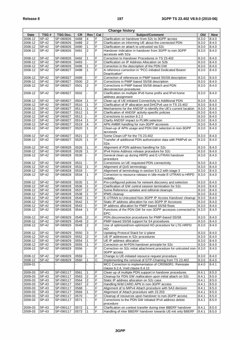
3GPP
3GPP TS 23.402 V8.9.0 (2010-06) 197Release 8
Change history Date TSG # TSG Doc. CR Rev Cat Subject/Comment Old New
2008-12 SP-42 SP-080826 0488 4 F Clarification on handover from S2c to 3GPP access 8.3.0 8.4.0 2008-12 SP-42 SP-080826 0489 2 F Clarification on informing UE about the connected PDN 8.3.0 8.4.0 2008-12 SP-42 SP-080826 0490 1 F Clarification on attach to untrusted via S2c 8.3.0 8.4.0 2008-12 SP-42 SP-080826 0491 2 F Handover indication in handover from 3GPP to non-3GPP
accesses with S2a 8.3.0 8.4.0
2008-12 SP-42 SP-080826 0492 1 F Correction to Handover Procedures in TS 23.402 8.3.0 8.4.0 2008-12 SP-42 SP-080826 0493 - F Clarification on IP Address Allocation on S2b 8.3.0 8.4.0 2008-12 SP-42 SP-080826 0496 1 F Correction in the description of the PDN GW 8.3.0 8.4.0 2008-12 SP-42 SP-080827 0498 1 F A reference correction in "PCC-initiated Dedicated Bearer
Deactivation" 8.3.0 8.4.0
2008-12 SP-42 SP-080827 0499 - F Correction of references in PMIP based S5/S8 description 8.3.0 8.4.0 2008-12 SP-42 SP-080827 0500 2 F Corrections in PMIP based S5/S8 description 8.3.0 8.4.0 2008-12 SP-42 SP-080827 0501 2 F Corrections in PMIP based S5/S8 detach and PDN
disconnection procedures 8.3.0 8.4.0
2008-12 SP-42 SP-080827 0502 - F Clarification on multiple IPv6 home prefix and IPv4 home address assignment
8.3.0 8.4.0
2008-12 SP-42 SP-080827 0504 1 F Clean-up of UE-initiated Connectivity to Additional PDN 8.3.0 8.4.0 2008-12 SP-42 SP-080827 0510 1 F Clarification of IP allocation and DHCPv6 use in TS 23.402 8.3.0 8.4.0 2008-12 SP-42 SP-080827 0511 1 F Mechanisms for the ANDSF to identify the UE's current location 8.3.0 8.4.0 2008-12 SP-42 SP-080827 0512 1 F Clarification of ANDSF activity-specific policies 8.3.0 8.4.0 2008-12 SP-42 SP-080827 0513 - F Corrections to section 8.2.2 8.3.0 8.4.0 2008-12 SP-42 SP-080827 0514 1 F Clarify ANDSF impact to PLMN selection 8.3.0 8.4.0 2008-12 SP-42 SP-080827 0519 4 F APN AMBR handling for non-3GPP accesses 8.3.0 8.4.0 2008-12 SP-42 SP-080827 0520 1 F Clean-up of APN usage and PDN GW selection in non-3GPP
accesses 8.3.0 8.4.0
2008-12 SP-42 SP-080827 0521 2 F Some Clean-UP for the TS 23.402 8.3.0 8.4.0 2008-12 SP-42 SP-080827 0525 1 F Transfer of additional PDN authorization data with PMIPv6 on
S2a 8.3.0 8.4.0
2008-12 SP-42 SP-080828 0526 1 F Alignment of PDN address handling for S2c 8.3.0 8.4.0 2008-12 SP-42 SP-080828 0528 1 F IPv4 Home Address release procedure for S2c 8.3.0 8.4.0 2008-12 SP-42 SP-080828 0530 - F General clean up during HRPD and E-UTRAN handover
procedure 8.3.0 8.4.0
2008-12 SP-42 SP-080828 0531 - F Corrections on UE requested PDN connectivity 8.3.0 8.4.0 2008-12 SP-42 SP-080828 0532 1 F Alignment of QoS terminology 8.3.0 8.4.0 2008-12 SP-42 SP-080828 0533 - F Alignment of terminology in section 9.3.2 with stage 3 8.3.0 8.4.0 2008-12 SP-42 SP-080828 0534 1 F Correction to resource release in idle-mode E-UTRAN to HRPD
mobility 8.3.0 8.4.0
2008-12 SP-42 SP-080828 0535 1 F Pre-configured policies for network discovery and selection 8.3.0 8.4.0 2008-12 SP-42 SP-080828 0536 1 F Clarification of GW control session termination for S2c 8.3.0 8.4.0 2008-12 SP-42 SP-080828 0537 2 F Some Reference updates and editorial cleanups 8.3.0 8.4.0 2008-12 SP-42 SP-080828 0538 1 F IPMS cleanup 8.3.0 8.4.0 2008-12 SP-42 SP-080828 0540 1 F E-UTRAN to Untrusted Non-3GPP IP Access Handover cleanup 8.3.0 8.4.0 2008-12 SP-42 SP-080828 0542 1 F Static IP address allocation for non 3GPP IP Accesses 8.3.0 8.4.0 2008-12 SP-42 SP-080828 0543 - F IP address allocation for PMIP based S5/S8 flows 8.3.0 8.4.0 2008-12 SP-42 SP-080828 0544 1 F Functions of the PDN GW for non-3GPP accesses connected to
EPC. 8.3.0 8.4.0
2008-12 SP-42 SP-080829 0545 2 F PDN disconnection procedures for PMIP-based S5/S8 8.3.0 8.4.0 2008-12 SP-42 SP-080829 0548 2 F PMIP-based S5/S8 support for S4 procedures 8.3.0 8.4.0 2008-12 SP-42 SP-080829 0549 2 F Use of optimized/non-optimized HO procedure for LTE-HRPD
HO 8.3.0 8.4.0
2008-12 SP-42 SP-080829 0550 3 F Updating Protocol Stack for U-plane 8.3.0 8.4.0 2008-12 SP-42 SP-080829 0552 2 F UE IP addresses in S2c procedures 8.3.0 8.4.0 2008-12 SP-42 SP-080829 0554 1 F UE IP address allocation 8.3.0 8.4.0 2008-12 SP-42 SP-080829 0555 1 F Correction on M-PDN handover principle for S2c 8.3.0 8.4.0 2008-12 SP-42 SP-080829 0556 - F Correction on S2c initial attachment procedure for untrusted non-
3GPP access 8.3.0 8.4.0
2008-12 SP-42 SP-080829 0559 - F Change to UE-initiated resource request procedure 8.3.0 8.4.0 2008-12 SP-42 SP-080829 0560 1 C Implementing the removal of GTP-Chaining from TS 23.402 8.3.0 8.4.0 2009-01 - - - - - MCC Correction to implementation of CR0560R1: Reinstate
clause 6.2.4, Void clause 6.4.12. 8.4.0 8.4.1
2009-03 SP-43 SP-090117 0561 1 F Clean up of multiple PDN support in handover procedures 8.4.1 8.5.0 2009-03 SP-43 SP-090117 0563 2 F Cleanup for PDN GW reallocation upon initial attach on S2c 8.4.1 8.5.0 2009-03 SP-43 SP-090117 0564 2 F Static IP address allocation on S2c case 8.4.1 8.5.0 2009-03 SP-43 SP-090117 0567 2 F Handling Wild CARD APN in non-3GPP access 8.4.1 8.5.0 2009-03 SP-43 SP-090117 0568 - F Alignment of to MIPv4 Attach procedure with SA3 decision 8.4.1 8.5.0 2009-03 SP-43 SP-090117 0569 1 F Alignment of Attach procedure with 23.203 8.4.1 8.5.0 2009-03 SP-43 SP-090117 0570 - F Cleanup of resources upon handover to non-3GPP access 8.4.1 8.5.0 2009-03 SP-43 SP-090117 0571 - F Corrections to the PDN GW initiated IPv4 address delete
procedure 8.4.1 8.5.0
2009-03 SP-43 SP-090117 0572 1 F Clarification on context transfer during inter BBERF handover 8.4.1 8.5.0 2009-03 SP-43 SP-090117 0573 1 F Handling of inter BBERF handover towards UE-init only BBERF 8.4.1 8.5.0

3GPP
3GPP TS 23.402 V8.9.0 (2010-06) 198Release 8
Change history Date TSG # TSG Doc. CR Rev Cat Subject/Comment Old New
2009-03 SP-43 SP-090117 0575 1 F Clean-up of section 8.4.2 8.4.1 8.5.0 2009-03 SP-43 SP-090117 0577 - F Alignment of S101 Tunnel Redirection message name with
Stage 3 8.4.1 8.5.0
2009-03 SP-43 SP-090117 0584 1 F Clarification on the request of the type of address on S2a 8.4.1 8.5.0 2009-03 SP-43 SP-090117 0586 2 F Removal of Non-3GPP network initiated PDN connection re-
establishment 8.4.1 8.5.0
2009-03 SP-43 SP-090118 0588 3 F Initial E-UTRAN Attach clarification 8.4.1 8.5.0 2009-03 SP-43 SP-090118 0590 2 F Corrections and Alignments in Annex C 8.4.1 8.5.0 2009-03 SP-43 SP-090118 0594 1 F Interaction between inter-system mobility policies and user
preferences 8.4.1 8.5.0
2009-03 SP-43 SP-090118 0595 2 F Clarification on path switch trigger for S2c-based handovers 8.4.1 8.5.0 2009-03 SP-43 SP-090118 0600 1 F Clarification on PLMN change triggered by ANDSF 8.4.1 8.5.0 2009-03 SP-43 SP-090118 0601 1 F ANDSF push not mandated in all access networks 8.4.1 8.5.0 2009-03 SP-43 SP-090118 0602 - F Clean-up of PCO handling with PMIPv6 on S2a 8.4.1 8.5.0 2009-03 SP-43 SP-090118 0603 1 F Reword Dedicated Bearer Deactivation sub-session title 8.4.1 8.5.0 2009-03 SP-43 SP-090118 0606 1 F Clarifications to IPv4 address allocation using DHCPv4 for S2a 8.4.1 8.5.0 2009-03 SP-43 SP-090118 0607 1 F HA discovery procedure 8.4.1 8.5.0 2009-03 SP-43 SP-090118 0610 - F Cleanup for some editorial corrections 8.4.1 8.5.0 2009-03 SP-43 SP-090118 0611 1 F Cleanup for handover between 3GPP Access and Trusted /
Untrusted Non-3GPP IP Access with access network discovery and selection
8.4.1 8.5.0
2009-03 SP-43 SP-090118 0612 - F Cleanup of S7 interface 8.4.1 8.5.0 2009-03 SP-43 SP-090118 0613 1 F Gateway Control Session establishment when IPMS capability is
not known 8.4.1 8.5.0
2009-03 SP-43 SP-090119 0615 - F Correction of the description of SWx 8.4.1 8.5.0 2009-03 SP-43 SP-090119 0616 - F PDN type checking in case of S2a and S2b and S2c 8.4.1 8.5.0 2009-03 SP-43 SP-090119 0621 - F Correction of IPv6 address allocation for S2c 8.4.1 8.5.0 2009-03 SP-43 SP-090119 0622 1 F Correction of incorrect references and old procedure names 8.4.1 8.5.0 2009-03 SP-43 SP-090119 0623 - F Correction of old-styled PCC procedures 8.4.1 8.5.0 2009-03 SP-43 SP-090119 0624 - F Correction of incorrect references to void section 8.4.1 8.5.0 2009-03 SP-43 SP-090119 0625 1 F Clarification of interface identifier allocation to UE in PMIP-based
S5/S8 case 8.4.1 8.5.0
2009-03 SP-43 SP-090119 0627 2 F Clarification of home link detection for IKEv2 SA via home link over non-3GPP access
8.4.1 8.5.0
2009-03 SP-43 SP-090119 0631 1 F Clarification on signalling of UE supported BCMs 8.4.1 8.5.0 2009-03 SP-43 SP-090119 0632 2 F Notification of assigned IP prefix in case of S2c 8.4.1 8.5.0 2009-03 SP-43 SP-090119 0633 1 F PMIP-based S5/S8 Update for User Location Signalling 8.4.1 8.5.0 2009-03 SP-43 SP-090119 0634 1 F PMIP-based S5/S8 Update for the usage of AMBR 8.4.1 8.5.0 2009-06 SP-44 SP-090338 0618 3 F On the charging Id in PMIP based S5/S8 core 8.5.0 8.6.0 2009-06 SP-44 SP-090338 0630 3 F "Charging Characteristics" receipt in PGW via PMIP 8.5.0 8.6.0 2009-06 SP-44 SP-090338 0640 1 F Correction to the PCC/QoS Principles 8.5.0 8.6.0 2009-06 SP-44 SP-090338 0642 1 F Clarification of access network information in HSS 8.5.0 8.6.0 2009-06 SP-44 SP-090338 0646 1 F S2a initial attach cleanup 8.5.0 8.6.0 2009-06 SP-44 SP-090338 0648 1 F Cleanup for IPv4 only indication on S2c 8.5.0 8.6.0 2009-06 SP-44 SP-090338 0657 - F Alignment to CT WG4 3GPP PMIPv6 Information Element name 8.5.0 8.6.0 2009-06 SP-44 SP-090338 0659 1 F Align the ATT value in PBU with the latest CT WG4 decision 8.5.0 8.6.0 2009-06 SP-44 SP-090339 0661 - F The corrections on the handover call flows from 3GPP to non-
3GPP access 8.5.0 8.6.0
2009-06 SP-44 SP-090339 0665 - F Usage of FQDN for PDN GW reallocation 8.5.0 8.6.0 2009-06 SP-44 SP-090339 0668 2 F PMIP-based S5/S8 support for Clarification on the SGSN
initiated bearer deactivation procedure 8.5.0 8.6.0
2009-06 SP-44 SP-090339 0670 3 F Alignment to CT4 GTPv2 Message Naming Conventions 8.5.0 8.6.0 2009-06 SP-44 SP-090339 0677 1 F Gateway Control Session establishment when IPMS capability is
not known 8.5.0 8.6.0
2009-06 SP-44 SP-090339 0679 - F Modification on the figure 5.2-1 in clause 5.2 8.5.0 8.6.0 2009-06 SP-44 SP-090339 0680 1 F The revision of IP Address Allocation clause 8.5.0 8.6.0 2009-06 SP-44 SP-090339 0681 1 F Correct the wording in 8.2.3 and 8.4.2 and 8.4.3 8.5.0 8.6.0 2009-06 SP-44 SP-090340 0682 1 F Modification of the error in Figure 9.3.2-1 E-UTRAN to HRPD
handover 8.5.0 8.6.0
2009-06 SP-44 SP-090340 0684 - F Alignment of S101 Redirection Procedure 8.5.0 8.6.0 2009-06 SP-44 SP-090340 0685 1 F Clarify the usage of AMBR for Trusted non-3GPP access 8.5.0 8.6.0 2009-06 SP-44 SP-090340 0686 1 F Clarification for PDN GW information Transmission 8.5.0 8.6.0 2009-06 SP-44 SP-090340 0692 1 F Removal of DHCP Client function from MAG in non-3GPP
access 8.5.0 8.6.0
2009-06 SP-44 SP-090340 0694 1 F Further clarifications to IPv4 address allocation using DHCPv4 for S2a
8.5.0 8.6.0
2009-06 SP-44 SP-090340 0705 - F Handling of TFT 8.5.0 8.6.0 2009-06 SP-44 SP-090341 0706 - F Update of IETF references 8.5.0 8.6.0 2009-06 SP-44 SP-090341 0708 1 F Editorial Correction in Figure 4.2.3-2 (Rel-8) 8.5.0 8.6.0 2009-06 SP-44 SP-090341 0709 1 F Editorial Correction in section 6.8.1.2 (Rel-8) 8.5.0 8.6.0 2009-06 SP-44 SP-090341 0746 - F Clarification on the APN-AMBR usage on P-GW 8.5.0 8.6.0

3GPP
3GPP TS 23.402 V8.9.0 (2010-06) 199Release 8
Change history Date TSG # TSG Doc. CR Rev Cat Subject/Comment Old New
2009-09 SP-45 SP-090590 0748 - F Corrections to BCM handling for S4-SGSN and PMIP-based S5/S8
8.6.0 8.7.0
2009-09 SP-45 SP-090590 0754 1 F Reference correction for S2c 8.6.0 8.7.0 2009-09 SP-45 SP-090590 0760 2 F Clarification for the home link detection function 8.6.0 8.7.0 2009-09 SP-45 SP-090590 0762 2 F Correction of S101 redirection procedure 8.6.0 8.7.0 2009-09 SP-45 SP-090590 0768 3 F Clarification for the AAA Server Behaviour During PDN-
Disconnection Procedure 8.6.0 8.7.0
2009-09 SP-45 SP-090590 0771 2 F Correction for Handover with Multiple PDN Connections and IP Preservation (R8)
8.6.0 8.7.0
2009-09 SP-45 SP-090590 0774 - F Removal of Annex D on Access Network Selection and Discovery
8.6.0 8.7.0
2009-09 SP-45 SP-090590 0775 - F Interference with PLMN selection used in I-WLAN access 8.6.0 8.7.0 2009-09 SP-45 SP-090590 0779 2 F PLMN reselection between HPLMN and EHPLMN 8.6.0 8.7.0 2009-09 SP-45 SP-090590 0786 3 F Complete Information Storage for TS 23.402 8.6.0 8.7.0 2009-09 SP-45 SP-090590 0790 1 F Clarification on powering interfaces up for handovers with
access network discovery and selection 8.6.0 8.7.0
2009-09 SP-45 SP-090590 0793 - F Removal of FFS related to synchronization of bearer establishment
8.6.0 8.7.0
2009-09 SP-45 SP-090590 0797 - F No unnecessary TFT Updates 8.6.0 8.7.0 2009-09 SP-45 SP-090590 0815 1 F Clarification that PLMN selection precedes any ANDSF
procedures 8.6.0 8.7.0
2009-12 SP-46 SP-090785 0836 2 D Remove empty section 14 - interaction with other services 8.7.0 8.8.0 2009-12 SP-46 SP-090785 0830 1 F HSS/AAA-initiated detach procedure for S2 8.7.0 8.8.0 2009-12 SP-46 SP-090785 0840 3 F Correction to APN-OI handling an inter-access handovers 8.7.0 8.8.0 2009-12 SP-46 SP-090785 0849 - F Clarification on the PDN GW selection for chained case 8.7.0 8.8.0 2009-12 SP-46 SP-090785 0851 - F Corrections to S2c Detach and PDN disconnection procedures. 8.7.0 8.8.0 2010-06 SP-48 SP-100316 0857 1 F Addition of the PGW Identity Information and APN Removal
Procedure 8.8.0 8.9.0
2010-06 SP-48 SP-100315 0877 - F Corrections to align S4 procedures for PMIP-based S5/S8 8.8.0 8.9.0 2010-06 SP-48 SP-100315 0879 1 F DNSv6 address allocation in PMIPv6 8.8.0 8.9.0 2010-06 SP-48 SP-100315 0881 - F Use of EAP-AKA' 8.8.0 8.9.0 2010-06 SP-48 SP-100315 0883 - F Correction of Request Type 8.8.0 8.9.0 2010-06 SP-48 SP-100315 0886 1 F Authentication for Non-3GPP 8.8.0 8.9.0 2010-06 SP-48 SP-100370 0902 - D Removing Editor's Notes from frozen specs 8.8.0 8.9.0