3gpp ts 23 - 一般社団法人 電波産業会 4 3gpp 4 3gpp ts 23.205 v4.11.0 (2006-09) 8.1.2.2...
TRANSCRIPT
3GPP TS 23.205 V4.11.0 (2006-09)Technical Specification
3rd Generation Partnership Project;Technical Specification Group Core Network;
Bearer-independent circuit-switched core network;Stage 2
(Release 4)
The present document has been developed within the 3rd Generation Partnership Project (3GPP TM) and may be further elaborated for the purposes of 3GPP. The present document has not been subject to any approval process by the 3GPP Organizational Partners and shall not be implemented. This Specification is provided for future development work within 3GPP only. The Organizational Partners accept no liability for any use of this Specification.Specifications and reports for implementation of the 3GPP TM system should be obtained via the 3GPP Organizational Partners' Publications Offices.

3GPP
3GPP TS 23.205 V4.11.0 (2006-09)2Release 4
Keywords UMTS, network, circuit mode
3GPP
Postal address
3GPP support office address 650 Route des Lucioles - Sophia Antipolis
Valbonne - FRANCE Tel.: +33 4 92 94 42 00 Fax: +33 4 93 65 47 16
Internet http://www.3gpp.org
Copyright Notification
No part may be reproduced except as authorized by written permission. The copyright and the foregoing restriction extend to reproduction in all media.
© 2006, 3GPP Organizational Partners (ARIB, ATIS, CCSA, ETSI, TTA, TTC).
All rights reserved.

3GPP
3GPP TS 23.205 V4.11.0 (2006-09)3Release 4
Contents Foreword ............................................................................................................................................................8 1 Scope ........................................................................................................................................................9 2 References ................................................................................................................................................9 3 Definitions, symbols and abbreviations .................................................................................................11 3.1 Symbols ........................................................................................................................................................... 11 3.2 Abbreviations................................................................................................................................................... 11 4 Main Concepts .......................................................................................................................................11 4.1 General............................................................................................................................................................. 11 4.2 Bearer-Independent Call Control ..................................................................................................................... 12 4.3 H.248/MEGACO ............................................................................................................................................. 12 5 General Circuit Switched Core Network Domain Architecture.............................................................12 5.1 Logical Architecture ........................................................................................................................................ 12 5.1.1 CS Core Network Nodes ............................................................................................................................ 12 5.1.1.1 MSC Server .......................................................................................................................................... 12 5.1.1.2 GMSC Server ....................................................................................................................................... 12 5.1.1.3 Media Gateway..................................................................................................................................... 12 5.1.2 CS Core Network Interfaces and Reference Points.................................................................................... 13 5.1.2.1 Mc Interface.......................................................................................................................................... 13 5.1.2.2 Nc Interface .......................................................................................................................................... 13 5.1.2.3 Nb Interface .......................................................................................................................................... 13 5.2 Network Interworking...................................................................................................................................... 13 5.2.1 Interworking on the Nc Reference Point .................................................................................................... 13 5.2.2 Interworking on the Nb Reference Point.................................................................................................... 13 6 Call Establishment .................................................................................................................................13 6.1 Basic Mobile Originating Call ......................................................................................................................... 13 6.1.1 Forward bearer establishment .................................................................................................................... 13 6.1.2 Backward bearer establishment.................................................................................................................. 17 6.2 Basic Mobile Terminating Call........................................................................................................................ 21 6.2.1 Forward bearer establishment .................................................................................................................... 21 6.2.1.1 GMSC server ........................................................................................................................................ 21 6.2.1.2 MSC server........................................................................................................................................... 23 6.2.2 Backward bearer establishment.................................................................................................................. 28 6.2.2.1 GMSC server ........................................................................................................................................ 28 6.2.2.2 MSC server........................................................................................................................................... 29 7 Call Clearing ..........................................................................................................................................35 7.1 Network Initiated ............................................................................................................................................. 35 7.1.1 GMSC server.............................................................................................................................................. 35 7.1.2 MSC server ................................................................................................................................................ 35 7.2 User Initiated ................................................................................................................................................... 37 7.2.1 Void............................................................................................................................................................ 38 7.2.2 MSC server ................................................................................................................................................ 38 7.3 (G)MSC server Initiated .................................................................................................................................. 39 7.3.1 GMSC server.............................................................................................................................................. 40 7.3.2 MSC server ................................................................................................................................................ 40 7.4 MGW Initiated................................................................................................................................................. 41 7.4.1 GMSC server.............................................................................................................................................. 42 7.4.2 MSC server ................................................................................................................................................ 42 8 Handover/Relocation..............................................................................................................................44 8.1 UMTS to UMTS .............................................................................................................................................. 45 8.1.1 Intra-MSC SRNS Relocation ..................................................................................................................... 45 8.1.2 Basic Inter-MSC SRNS Relocation ........................................................................................................... 48 8.1.2.1 MSC-A/MGW-A.................................................................................................................................. 48

3GPP
3GPP TS 23.205 V4.11.0 (2006-09)4Release 4
8.1.2.2 MSC-B/MGW-B .................................................................................................................................. 49 8.1.3 Subsequent Inter-MSC SRNS Relocation back to the Anchor MSC ......................................................... 52 8.1.3.1 MSC-A/MGW-A.................................................................................................................................. 52 8.1.3.2 MSC-B/MGW-B .................................................................................................................................. 53 8.1.4 Subsequent Inter-MSC SRNS Relocation to a third MSC ......................................................................... 56 8.2 UMTS to GSM ................................................................................................................................................ 56 8.2.1 Intra-MSC UMTS to GSM Handover ........................................................................................................ 56 8.2.2 Basic Inter-MSC UMTS to GSM Handover .............................................................................................. 61 8.2.2.1 MSC-A/ MGW-A................................................................................................................................. 61 8.2.2.2 MSC-B / MGW-B ................................................................................................................................ 62 Voice Processing function ................................................................................................................................................ 62 8.2.3 Subsequent Inter-MSC UMTS to GSM Handover back to the Anchor MSC ............................................ 65 8.2.3.1 MSC-A ................................................................................................................................................. 66 8.2.3.2 MSC-B.................................................................................................................................................. 66 8.2.4 Subsequent Inter-MSC UMTS to GSM Handover to a third MSC ............................................................ 71 8.3 GSM to UMTS ................................................................................................................................................ 71 8.3.1 Intra-MSC GSM to UMTS Handover ........................................................................................................ 71 8.3.2 Basic Inter-MSC GSM to UMTS Handover .............................................................................................. 75 8.3.2.1 MSC-A ................................................................................................................................................. 75 8.3.2.2 MSC-B.................................................................................................................................................. 75 8.3.3 Subsequent Inter-MSC GSM to UMTS Handover back to the Anchor MSC ............................................ 79 8.3.3.1 MSC-A ................................................................................................................................................. 80 8.3.3.2 MSC-B / MGW-B ................................................................................................................................ 80 8.3.4 Subsequent Inter-MSC GSM to UMTS Handover to a third MSC ............................................................ 83 8.4 GSM to GSM................................................................................................................................................... 84 8.4.1 Intra-MSC GSM to GSM Handover .......................................................................................................... 84 8.4.2 Basic Inter-MSC GSM to GSM Handover................................................................................................. 87 8.4.2.1 MSC-A / MGW-A................................................................................................................................ 87 8.4.2.2 MSC-B / MGW-B ................................................................................................................................ 88 8.4.3 Subsequent Inter-MSC GSM to GSM Handover back to the Anchor MSC............................................... 92 8.4.3.1 MSC-A / MGW-A................................................................................................................................ 92 8.4.3.2 MSC-B / MGW-B ................................................................................................................................ 92 8.4.4 Subsequent GSM to GSM Handover to a third MSC................................................................................. 96 8.5 Handling of GSM Services after UMTS to GSM Handover ........................................................................... 96 9 Compatibility Issues...............................................................................................................................96 9.1 Interworking with GERAN (A i/f)................................................................................................................... 96 10 General (G)MSC server-MGW Procedures ...........................................................................................97 10.1 MGW Unavailable........................................................................................................................................... 97 10.2 MGW Available............................................................................................................................................... 98 10.3 MGW Recovery............................................................................................................................................... 99 10.4 (G)MSC server Recovery ................................................................................................................................ 99 10.4.1 General ....................................................................................................................................................... 99 10.4.2 (G)MSC Server Restoration ....................................................................................................................... 99 10.5 MGW Re-register .......................................................................................................................................... 100 10.6 MGW Re-registration Ordered by (G)MSC server........................................................................................ 100 10.7 Removal from Service of a Physical Termination ......................................................................................... 100 10.8 Restoration to Service of a Physical Termination.......................................................................................... 101 10.9 Audit of MGW............................................................................................................................................... 101 10.9.1 Audit of Value.......................................................................................................................................... 101 10.9.2 Audit of Capability................................................................................................................................... 102 10.10 MGW Capability Change .............................................................................................................................. 102 10.11 Void ............................................................................................................................................................... 103 10.12 (G)MSC Server Out of service ...................................................................................................................... 103 11 Identities...............................................................................................................................................103 11.1 Bearer Address and Binding Reference ......................................................................................................... 103 11.2 MGW-Id ........................................................................................................................................................ 103 11.3 (G)MSC server Address................................................................................................................................. 103 12 Operational Aspects .............................................................................................................................103 12.1 Charging ........................................................................................................................................................ 103

3GPP
3GPP TS 23.205 V4.11.0 (2006-09)5Release 4
13 Interactions with Other Services ..........................................................................................................104 13.1 enhanced Multi-Level Precedence and Pre-emption service (eMLPP).......................................................... 104 13.2 Call Deflection Service.................................................................................................................................. 104 13.3 Line identification Services ........................................................................................................................... 106 13.3.1 Calling Line Identification Presentation (CLIP) ...................................................................................... 106 13.3.2 Calling Line Identification Restriction (CLIR) ........................................................................................ 106 13.3.3 Connected Line Identification Presentation (COLP)................................................................................ 106 13.3.4 Connected Line Identification Restriction (COLR) ................................................................................. 106 13.4 Call Forwarding Services............................................................................................................................... 107 13.4.1 Call Forwarding Unconditional (CFU) .................................................................................................... 107 13.4.2 Call Forwarding on mobile subscriber Busy (CFB)................................................................................. 108 13.4.2.1 Network Determined User Busy (NDUB).......................................................................................... 108 13.4.2.2 User Determined User Busy (UDUB) ................................................................................................ 111 13.4.3 Call Forwarding on No Reply (CFNRy) .................................................................................................. 114 13.4.4 Call Forwarding on mobile subscriber Not Reachable (CFNRc) ............................................................. 116 13.4.4.1 Rerouting by HLR .............................................................................................................................. 116 13.4.4.2 Rerouting by VLR .............................................................................................................................. 116 13.5 Call Waiting (CW)......................................................................................................................................... 119 13.5.1 Call Confirmation of the waiting call....................................................................................................... 120 13.5.2 Acceptance of the Waiting Call................................................................................................................ 121 13.6 Call Hold (CH) .............................................................................................................................................. 121 13.7 Multiparty (MPTY)........................................................................................................................................ 124 13.8 Closed User Group (CUG)............................................................................................................................. 128 13.9 Advice of Charge (AoC)................................................................................................................................ 128 13.10 User-to-User Signalling (UUS)...................................................................................................................... 128 13.11 Call Barring Services ..................................................................................................................................... 128 13.11.1 Barring of outgoing calls.......................................................................................................................... 128 13.11.2 Barring of incoming calls......................................................................................................................... 128 13.12 Explicit Call Transfer (ECT) ......................................................................................................................... 128 13.13 Completion of Calls to Busy Subscriber (CCBS) .......................................................................................... 131 13.13.1 Clearing when tones/announcements are provided to the calling subscriber ........................................... 131 13.13.2 Network initiated mobile originated call.................................................................................................. 131 13.13.2.1 Early Traffic Channel Assignment ..................................................................................................... 132 13.13.3 CCBS Information conveyed by Call Signalling ..................................................................................... 132 13.14 Multiple Subscriber Profile (MSP) ................................................................................................................ 133 13.15 Multicall......................................................................................................................................................... 133 13.16 Calling Name Presentation (CNAP) .............................................................................................................. 133 13.17 Alternate Speech/Fax..................................................................................................................................... 133 13.18 Modification of the Access Bearer................................................................................................................. 133 13.18.1 Modification of Bearer Characteristics .................................................................................................... 133 13.18.2 IWF Protocol Change............................................................................................................................... 134 13.19 GSM Fax........................................................................................................................................................ 134 14 Interactions with Other Network Features and Services ......................................................................135 14.1 Customised Applications for Mobile network Enhanced Logic (CAMEL)................................................... 135 14.1.1 Play Announcement/Send Tone ............................................................................................................... 136 14.1.2 User Interaction........................................................................................................................................ 136 14.2 IST ................................................................................................................................................................. 137 14.3 Operator Determined Barring (ODB) ............................................................................................................ 137 14.3.1 Barring of Outgoing Calls ........................................................................................................................ 137 14.3.2 Barring of Incoming Calls........................................................................................................................ 137 14.4 DTMF ............................................................................................................................................................ 138 14.4.1 DTMF Tone Generation........................................................................................................................... 138 14.4.1.1 Inband DTMF Tone Generation ......................................................................................................... 138 14.4.1.2 Out-of-Band DTMF Tone Generation................................................................................................ 139 14.4.2 DTMF Detection ...................................................................................................................................... 140 14.4.2.1 Inband DTMF Detection .................................................................................................................... 140 14.4.2.2 Out-of-Band DTMF Detection ........................................................................................................... 140 14.5 OR.................................................................................................................................................................. 141 14.5.1 Optimal routeing for basic mobile-to-mobile calls................................................................................... 141 14.5.2 Optimal routeing for conditional call forwarding; Early call forwarding ................................................ 141 14.5.3 Optimal routeing for conditional call forwarding; Late call forwarding .................................................. 141

3GPP
3GPP TS 23.205 V4.11.0 (2006-09)6Release 4
14.5.3.1 MSC server......................................................................................................................................... 141 14.5.3.2 GMSC server ...................................................................................................................................... 141 14.6 Providing tones or announcements ................................................................................................................ 145 15 Tunnelling ............................................................................................................................................147 15.1 Forward Bearer Establishment....................................................................................................................... 147 15.1.1 Outgoing Side .......................................................................................................................................... 147 15.1.2 Incoming Side .......................................................................................................................................... 148 15.2 Backward Bearer Establishment .................................................................................................................... 151 15.2.1 Outgoing Side .......................................................................................................................................... 151 15.2.2 Incoming Side .......................................................................................................................................... 152 16 Messages/Procedures and their contents ..............................................................................................154 16.1 Messages between (G)MSC servers .............................................................................................................. 154 16.2 Procedures between (G)MSC server and MGW............................................................................................ 156 16.2.1 Change Flow Direction ............................................................................................................................ 156 16.2.2 Join Bearer Termination........................................................................................................................... 157 16.2.3 Isolate Bearer Termination....................................................................................................................... 157 16.2.4 Establish Bearer ....................................................................................................................................... 158 16.2.5 Prepare Bearer.......................................................................................................................................... 159 16.2.6 Reserve Circuit......................................................................................................................................... 160 16.2.7 Change Through-Connection ................................................................................................................... 161 16.2.8 Activate Interworking Function ............................................................................................................... 161 16.2.9 Release Bearer.......................................................................................................................................... 161 16.2.10 Bearer Established.................................................................................................................................... 162 16.2.11 Bearer Released........................................................................................................................................ 163 16.2.12 Release Termination................................................................................................................................. 163 16.2.13 Tunnel Information Up ............................................................................................................................ 164 16.2.14 Tunnel Information Down........................................................................................................................ 164 16.2.15 Send Tone ................................................................................................................................................ 164 16.2.16 Stop Tone ................................................................................................................................................. 165 16.2.17 Play Announcement ................................................................................................................................. 165 16.2.18 Stop Announcement ................................................................................................................................. 166 16.2.19 Announcement Completed....................................................................................................................... 167 16.2.20 Tone Completed ....................................................................................................................................... 167 16.2.21 Detect DTMF ........................................................................................................................................... 167 16.2.22 Stop DTMF Detection.............................................................................................................................. 168 16.2.23 Report DTMF........................................................................................................................................... 169 16.2.24 Send DTMF.............................................................................................................................................. 169 16.2.25 Stop DTMF .............................................................................................................................................. 170 16.2.26 MGW Out-of-Service............................................................................................................................... 170 16.2.27 MGW Communication Up ....................................................................................................................... 171 16.2.28 MGW Restoration .................................................................................................................................... 171 16.2.29 MGW Register ......................................................................................................................................... 172 16.2.30 MGW Re-register..................................................................................................................................... 172 16.2.31 (G)MSC Server Ordered Re-register........................................................................................................ 173 16.2.32 (G)MSC Server Restoration ..................................................................................................................... 173 16.2.33 (G)MSC Server Out of Service ................................................................................................................ 174 16.2.34 Termination Out-of-Service ..................................................................................................................... 174 16.2.35 Termination Restoration........................................................................................................................... 175 16.2.36 Audit Value .............................................................................................................................................. 175 16.2.37 Audit Capability ....................................................................................................................................... 176 16.2.38 Capability Update..................................................................................................................................... 176 16.2.39 Command Reject...................................................................................................................................... 177 16.2.40 Activate Voice Processing Function ........................................................................................................ 177 16.2.41 Modify Bearer Characteristics ................................................................................................................. 178 16.2.42 IWF Protocol Indication........................................................................................................................... 178 16.2.43 Bearer Modification Support.................................................................................................................... 179 16.2.44 Rate Change ............................................................................................................................................. 179 16.2.45 Bearer Modified................................................................................................................................................. 180 16.2.46 Bearer Modification Failed ................................................................................................................................ 180 16.2.47 Continuity Check Tone ............................................................................................................................ 180

3GPP
3GPP TS 23.205 V4.11.0 (2006-09)7Release 4
16.2.48 Continuity Check Verify .......................................................................................................................... 181 16.2.49 Continuity Check Response ..................................................................................................................... 181 17 Bearer Redirect.....................................................................................................................................182 17.1 Example of use of Bearer Redirect with Call Forwarding on No Reply (CFNRy)........................................ 182 18 (G)MSC MGW Tandeming .................................................................................................................185 18.1 Example of use of MSC MGW Tandeming during call setup to provide bearer access to specialised
MGW resources. ............................................................................................................................................ 185 19 Timers for bearer independent CS core network..................................................................................186
Annex A (informative): Change History ............................................................................................187
3GPP
3GPP TS 23.205 V4.11.0 (2006-09)8Release 4
Foreword This Technical Specification has been produced by the 3rd Generation Partnership Project (3GPP).
The contents of the present document are subject to continuing work within the TSG and may change following formal TSG approval. Should the TSG modify the contents of the present document, it will be re-released by the TSG with an identifying change of release date and an increase in version number as follows:
Version x.y.z
where:
x the first digit:
1 presented to TSG for information;
2 presented to TSG for approval;
3 or greater indicates TSG approved document under change control.
y the second digit is incremented for all changes of substance, i.e. technical enhancements, corrections, updates, etc.
z the third digit is incremented when editorial only changes have been incorporated in the document.

3GPP
3GPP TS 23.205 V4.11.0 (2006-09)9Release 4
1 Scope The present document defines the stage 2 description for the bearer independent CS core network. The stage 2 shall cover the information flow between the GMSC server, MSC server and media gateways. Note that nothing in the present document shall preclude an implementation of a combined MSC Server and MGW. The present document shall show the CS core network termination of the Iu interface in order to cover the information flow stimulus to the core network and describe the interaction with the supplementary and value added services and capabilities.
For the purposes of the present document, the protocol used over the Nc interface is an enhanced call control protocol supporting call bearer separation such as BICC (which is specified in [22]). The protocol used over the Mc interface is H.248 (which is specified in [5]). Existing specifications and recommendations shall not be repeated, as such the relevant specification shall be referred to.
The present document is applicable only for ATM or IP transport in the CS core network.
MGW
Signalling and Data TransferInterface
SignallingInterface
UTRAN PSTN/Legacy/External
HLRApplications& Services
MSC server GMSC server
Mc
D C
MGWNb
Nc
Iu
Iu
CAPCAP
Mc
GERAN
A
A
Figure 1: CS core network logical architecture
The CAP interfaces and the interfaces towards the HLR are outside the scope of the present document.
Details of Transcoder-Free Operation are outside the scope of the present document. Please see 3GPPTS 23.153 [3] for more information.
2 References The following documents contain provisions which, through reference in this text, constitute provisions of the present document.
• References are either specific (identified by date of publication, edition number, version number, etc.) or non-specific.
• For a specific reference, subsequent revisions do not apply.
• For a non-specific reference, the latest version applies. In the case of a reference to a 3GPP document (including a GSM document), a non-specific reference implicitly refers to the latest version of that document in the same Release as the present document.
[1] 3GPP TR 21.905: "Vocabulary for 3GPP Specifications".
[2] 3GPP TS 23.002: "Network Architecture".
[3] 3GPP TS 23.153: "Out of Band Transcoder Control; Stage 2".

3GPP
3GPP TS 23.205 V4.11.0 (2006-09)10Release 4
[4] 3GPP TS 24.008: "Mobile Radio Interface Layer 3 specification; Core Network Protocols; Stage 3".
[5] ITU-T Recommendation H.248: "Gateway Control Protocol".
[6] 3GPP TS 29.232: "Media Gateway Controller (MGC); Media Gateway (MGW) interface; Stage 3".
[7] 3GPP TS 29.415: "Core Network Nb User Plane Protocols; Stage 3".
[8] 3GPP TS 23.009: "Handover procedures".
[9] 3GPP TS 23.072: "Call Deflection (CD) supplementary service; Stage2".
[10] 3GPP TS 23.078: "Customized Applications for Mobile network Enhanced Logic (CAMEL) - Phase 3; Stage 2".
[11] 3GPP TS 23.079: "Support of Optimal Routeing (SOR); Technical Realisation".
[12] 3GPP TS 23.082: "Call Forwarding (CF) Supplementary Services; Stage 2".
[13] 3GPP TS 23.083: "Call Waiting (CW) and Call Hold (HOLD) Supplementary Services; Stage 2".
[14] 3GPP TS 23.084: "Digital cellular telecommunications system (Phase 2+); Multi Party (MPTY) Supplementary Service; Stage 2".
[15] 3GPP TS 23.091: "Explicit Call Transfer (ECT) Supplementary Service; Stage 2".
[16] 3GPP TS 23.093: "Technical realisation of Completion of Calls to Busy Subscriber (CCBS); Stage 2".
[17] 3GPP TS 23.135: "Multicall supplementary service; Stage 2".
[18] 3GPP TS 23.108: "Mobile radio interface layer 3 specification; Core Network Protocols; Stage 2".
[19] GSM TS 02.32: "Immediate Service Termination (IST); Service Description; Stage 1".
[20] 3GPP TS 25.415: "UTRAN Iu Interface User Plane Protocols".
[21] 3GPP TS 29.414: "Core Network Nb Data Transport and Transport Signalling".
[22] 3GPP TS 29.205: "Application of Q.1900 Series to Bearer Independent circuit-switched core network architecture; Stage 3".
[23] 3GPP TS 29.010: "Information element mapping between Mobile Station - Base Station System (MS - BSS) and Base Station System - Mobile-services Switching Centre (BSS - MSC); Signalling procedures and the Mobile Application Part (MAP)".
[24] GSM TS 03.45: "Technical realization of facsimile group 3 transparent".
[25] 3GPP TS 23.146: "Technical realization of facsimile group 3 non-transparent".
[26] 3GPP TS 25.413: "UTRAN Iu Interface RANAP Signalling"
[27] 3GPP TS 48.008: "Mobile-services Switching Centre – Base Station System (MSC – BSS) interface; layer 3 specification"
[28] 3GPP TS 23.014: "Technical Specification Group Core Network; Support of Dual Tone Multi-Frequency (DTMF) signalling".

3GPP
3GPP TS 23.205 V4.11.0 (2006-09)11Release 4
3 Definitions, symbols and abbreviations
3.1 Symbols For the purposes of the present document, the following symbols apply:
Iu Interface between the RNS and the core network. It is also considered as a reference point. Mc Interface between the server and the media gateway. Nb Interface between media gateways. Nc The NNI call control interface between (G)MSC servers.
3.2 Abbreviations For the purposes of the present document, the following abbreviations apply:
BCF Bearer Control Function BICC Bearer Independent Call Control CIC Call Instance Code CCF Call Control Function CS Circuit Switched IAM Initial Address Message IETF Internet Engineering Task Force IP Internet Protocol IPv4 Internet Protocol version 4 IPv6 Internet Protocol version 6 MGW Media Gateway MGC Media Gateway Controller MSC-S MSC Server MTP2 Message Transfer Part layer 2 MTP3 Message Transfer Part layer 3 NNI Network-Network interface RAB Radio Access Bearer RANAP Radio Access Network Application Protocol TCAP Transaction Capabilities Application Part TFO Tandem free operation TRAU Transcoder and Rate Adapter Unit TrFO Transcoder free operation UDP User Datagram Protocol UTRAN UMTS Terrestrial Radio Access Network
4 Main Concepts
4.1 General The circuit switched core network enables the support of different transports (e.g. ATM or IP) in a bearer-independent fashion. For the ATM and IP transport, there is a strict separation between the call control level and the bearer control level. In the case of ATM or IP transport, the passage of compressed speech at variable bit rates is possible through the CS core network.
The CS core network shall employ the MSC server, GMSC server and media gateways. The GMSC server and MSC server shall provide the call control and mobility management functions, and the media gateway shall provide the bearer control and transmission resource functions. The media gateway shall contain the stream manipulating functions.
The GMSC server and MSC servers are connected to the media gateway via the Mc reference point. The MSC servers and GMSC servers are connected with the Nc reference point. There may be a number of call control transit nodes
3GPP
3GPP TS 23.205 V4.11.0 (2006-09)12Release 4
between the MSC server and GMSC server in the Nc reference point. The MGWs are connected with the Nb reference point.
The users connected to the CS core network shall not be aware whether a MSC server – media gateway combination is used, or a monolithic MSC is used.
4.2 Bearer-Independent Call Control The protocol used on the Nc interface shall be a call control protocol supporting IP and ATM transports in a bearer-independent manner for the ISDN service set, allowing the physical separation of the call control entities from the bearer control entities.
4.3 H.248/MEGACO H.248/MEGACO has been jointly developed within the ITU-T and the IETF, and supports a separation of call control entities from bearer control entities, and a separation of bearer control entities from transport entities. H.248 is used on the Mc interface between the (G)MSC servers and the media gateway.
5 General Circuit Switched Core Network Domain Architecture
5.1 Logical Architecture The overall CS core network logical architecture is shown in figure 1.
5.1.1 CS Core Network Nodes
5.1.1.1 MSC Server
The MSC server mainly comprises the call control and mobility control parts of a GSM/UMTS MSC as described in 3GPP TS 23.002 [2]. It is also integrated with a VLR to hold the mobile subscriber's service data and CAMEL related data.
The MSC server terminates the user-network signalling (see 3GPP TS 24.008 [4]) and translates it into the signalling over the Nc interface. It also terminates the signalling over the Mc interface with the media gateway.
The MSC server controls the parts of the call state model that pertain to connection control for media channels in an MGW. It also contains the 'Call Control Function' in the BICC model.
5.1.1.2 GMSC Server
The GMSC server mainly comprises the call control and mobility control parts of a GSM/UMTS GMSC as described in 3GPP TS 23.002 [2].
The GMSC server terminates the signalling over the Nc interface and the call control interfaces to the external networks. It also terminates the signalling over the Mc interface towards the media gateway.
The GMSC server controls the parts of the call state model that pertain to connection control for media channels in an MGW. It also contains the 'Call Control Function' in the BICC model
5.1.1.3 Media Gateway
The media gateway terminates the signalling over the Mc interface from the (G)MSC servers. It also terminates the bearer part of the signalling over the Iu interface and the Nb interface.

3GPP
3GPP TS 23.205 V4.11.0 (2006-09)13Release 4
The media gateway contains bearer terminations and media manipulation equipment (e.g. transcoders, echo cancellers, or tone senders). It may perform media conversion and framing protocol conversion.
5.1.2 CS Core Network Interfaces and Reference Points
5.1.2.1 Mc Interface
The Mc reference point in the present document considers the aspects of the interface between the (G)MSC server and the MGW. The H.248 protocol [5] together with 3GPP specific extensions/packages shall be used over the Mc interface.
5.1.2.2 Nc Interface
The Network-Network based call control is used over the Nc interface. Any suitable call control protocol may be used over the Nc interface (e.g. BICC).
5.1.2.3 Nb Interface
The bearer control signalling and transport are carried over the Nb interface.
5.2 Network Interworking
5.2.1 Interworking on the Nc Reference Point Interworking between the Nc reference point, call control protocols and ISUP is defined within the 3GPP stage 3 documentation for each protocol (or by references specified in stage 3 documentation [6]).
5.2.2 Interworking on the Nb Reference Point The interworking is specified in 3GPP TS 29.415 [7] and 3GPP TS 29.414 and [21].
6 Call Establishment NOTE1: All message sequence charts in this clause are examples. All valid call establishment message sequences
can be derived from the example message sequences and associated message pre-conditions.
NOTE2: The continuity indication in the IAM is not used to indicate that a continuity check will be performed on the current leg of the call, but it is used to indicate that a Continuity message can be expected as a result of a continuity check on a preceding ISUP circuit, or establishment of a preceding bearer connection.
6.1 Basic Mobile Originating Call
6.1.1 Forward bearer establishment The mobile originating call shall be established in accordance with 3GPP TS 23.108 [17]. The following paragraphs describe the additional requirements for the bearer independent CS core network. If out-of-band transcoder control is applied for a speech call, it shall be performed in accordance with 3GPP TS 23.153 [3].
MGW selection
The MSC server shall select an MGW for the bearer connection before it performs the access bearer assignment or the network side bearer establishment. This may happen either before sending the IAM or after receiving the Bearer Information message. In the latter case, the MGW selection may be based on a possibly received MGW-id from the succeeding node (bullet 1 or bullet 2 in figure 6.2).

3GPP
3GPP TS 23.205 V4.11.0 (2006-09)14Release 4
Initial addressing
The MSC server shall indicate in the IAM that forward bearer establishment is to be used. If access bearer assignment has not been completed, the MSC server shall indicate that the Continuity message will follow. However, if late access bearer assignment (assignment after alerting or answer) is used the MSC server shall not indicate that the Continuity message will follow. The MSC server provides the bearer characteristics to the succeeding node in the IAM. If the MGW is selected at an earlier stage the MGW-id may also be provided in the IAM (bullet 1 in figure 6.2).
Network side bearer establishment
The MSC server shall either select bearer characteristics or requests the MGW to select and provide the bearer characteristics for the network side bearer connection before sending the IAM. In the latter case the MSC server uses the Prepare Bearer procedure to request the MGW to select the bearer characteristics. After the succeeding node has provided a bearer address and a binding reference in the Bearer Information message the MSC server uses the Establish Bearer procedure to request the MGW to establish a bearer towards the destination MGW. The MSC server provides the MGW with the bearer address, the binding reference and the bearer characteristics (bullet 2 in figure 6.2).
Access bearer assignment
The MSC server shall select bearer characteristics for the access bearer.
For UTRAN, before the MSC server starts the access bearer assignment, the MSC server requests the MGW to prepare for the access bearer establishment using the Prepare Bearer procedure. The MSC server requests the MGW to provide a bearer address and a binding reference, provides the MGW with the bearer characteristics and requests notification that the bearer can be modified. For speech calls, the MSC server shall provide the MGW with the speech coding information for the bearer. For a non-speech call the MSC server also provides the MGW with a PLMN Bearer Capability [4]. After the MGW has replied with the bearer address and the binding reference the MSC server requests access bearer assignment using the provided bearer address and binding reference (bullet 3 in figure 6.2) in accordance with 3GPP TS 25.413 [26]. The MSC shall only be notified by the MGW using Bearer Modification Support procedure if the existing link characteristics of the access bearer can be modified at a later stage, see subclause 13.18.1..
For GERAN, before the MSC server starts the access bearer assignment, the MSC server uses the Reserve Circuit procedure to seize a TDM circuit. For a non-speech call the MSC server also provides the MGW with a PLMN Bearer Capability [4] and a GSM channel coding. After the MGW has replied to the TDM circuit seizure, the MSC server requests access bearer assignment (bullet 4 in figure 6.2) in accordance with 3GPP TS 48.008 [27].
Framing protocol initialisation
In 3GPP CS CN speech and data shall be carried using the Iu/Nb User Plane Protocol. The specification for the Iu UP protocol is defined in [20] and the Nb UP Protocol in [7] and [21]. The Iu/Nb UP Protocol is established through the CN in a forward direction. This is established independently of the bearer establishment direction. The MGW derives the forward direction from information sent by the MSC server within the Establish Bearer and Prepare Bearer procedures [6].
Confirmation of bearer establishment
If the IAM which was sent to the succeeding node indicated that the Continuity message will follow, the MSC server sends the Continuity message when the access bearer assignment has been completed (bullet 5 in figure 6.2).
Through-Connection
During any one of the Prepare Bearer, Reserve Circuit and Establish Bearer procedures, the MSC server will use the Change Through-Connection procedure to request the MGW to through-connect the bearer terminations so that the bearer will be backward through-connected (bullet 2, and bullet 3 or 4 in figure 6.2).
When the MSC server receives the answer indication, it requests the MGW to both-way through-connect the bearer using the Change Through-Connection procedure (bullet 6 in figure 6.2).
Interworking function
The MGW may use an interworking function that is based on the PLMN Bearer Capability [4] of the bearer termination. The activation of the possible interworking function in both bearer terminations will be requested by the

3GPP
3GPP TS 23.205 V4.11.0 (2006-09)15Release 4
MSC server at reception of the answer indication using the Activate Interworking Function procedure (bullet 6 in figure 6.2).
Codec handling
The MGW may include a speech transcoder based upon the speech coding information provided to each bearer termination.
Voice Processing function
A voice processing function located on the MGW may be used to achieve desired acoustic quality on the bearer terminations. The MSC server shall request the activation of voice processing functions in the bearer terminations. For non-speech calls, the MSC server has the ability to instruct the MGW to disable the voice processing functions (bullet 6 in figure 6.2).
Failure handling in MSC server
If any procedure between the MSC server and the MGW has not completed successfully or the MSC server receives a Bearer Released procedure from the MGW, the call shall be cleared as described in clause 7.3, (G)MSC server initiated call clearing or in clause 7.4, MGW initiated call clearing. Alternatively, the MSC server may only release the resources in the MGW that caused the failure, possibly select a new MGW for the bearer connection and continue the call establishment using new resources in the selected MGW.
Example
Figure 6.1 shows the network model for the mobile originating call. The 'squared' line represents the call control signalling. The 'dotted' line represents the bearer control signalling (not applicable in A-interface) and the bearer. The MSC server seizes one context with two bearer terminations in the MGW. The bearer termination T1 is used for the bearer towards the RNC/BSC and the bearer termination T2 is used for the bearer towards the succeeding MGW.
MGW
MSC-S
CTX1T1 T2
RNC/BSC
Figure 6.1 Basic Mobile Originating Call, Forward Bearer Establishment (network model)
Figure 6.2 shows the message sequence chart example for the mobile originating call. In the example the MSC server requests seizure of the network side bearer termination and establishment of the bearer when the Bearer Information message is received from the succeeding node. After the network side bearer termination is seized the MSC server requests seizure of the access side bearer termination. When the MSC server receives an answer indication, it shall requests the MGW to both-way through-connect the bearer terminations. The MSC shall also request the possible activation of the interworking function in both terminations and the possible activation of the voice processing functions for the bearer terminations.

3GPP
3GPP TS 23.205 V4.11.0 (2006-09)16Release 4
Bearer Establishment
GSM:
Reserve Circuit + Change Through-Connection Context (C1) ADD.reply (T1)
ASSIGNMENT REQUEST
ASSIGNMENT COMPL
Context (C1) ADD.request (T1)4
UMTS:
Establish Bearer + Change Through-Connection
Prepare Bearer + Change Through-Connection
Continuity
Context (C1) ADD.reply (T1)
RAB ASSIGNMENT REQ
RAB ASSIGNMENT COMPL
Bearer Establishment and Iu UP Initialization
Context (C1) ADD.reply (T2)
Context ($) ADD.request ($)
Bearer Information
Context (C1) ADD.request ($)
Initial Address CALL PROCEEDING
SETUP
UE RNC/BSC MSC-S MGW
2
3
5
1
UP Init
UP Init Ack
Figure 6.2/1 Basic Mobile Originating Call, Forward Bearer Establishment (message sequence chart)

3GPP
3GPP TS 23.205 V4.11.0 (2006-09)17Release 4
Context (C1) MOD.reply (T2)
Context (C1) MOD.request (T2)
Context (C1) MOD.reply (T1)
Context (C1) MOD.request (T1)6
CONNECT
ALERTINGAnswer
Address Complete
UE RNC/BSC MSC-S MGW
Change Through-Connection +Activate Inter-Working Function(when applicable) +Activate Voice ProcessingFunction (when applicable)
Activate Inter-WorkingFunction (when applicable) +Activate Voice ProcessingFunction (when applicable)
Figure 6.2/2 Basic Mobile Originating Call, Forward Bearer Establishment (message sequence chart continue)
6.1.2 Backward bearer establishment The basic mobile originating call shall be established in accordance with 3GPP TS 23.108 [17]. The following paragraphs describe the additional requirements for the bearer independent CS core network. If out-of-band transcoder control is applied for a speech call, it shall be performed in accordance with 3GPP TS 23.153 [3].
MGW selection
The MSC server shall select an MGW for the bearer connection before it performs the access bearer assignment or the network side bearer establishment. This happens before sending the IAM (bullet 1 or 2 in figure 6.4).
Network side bearer establishment
The MSC server shall either select preferred bearer characteristics or requests the MGW to select and provide the bearer characteristics for the network side bearer connection before sending the IAM. The MSC server requests the MGW to prepare for the network side bearer establishment using the Prepare Bearer procedure. The MSC server requests the MGW to provide a bearer address and a binding reference, and provides the MGW with the preferred bearer characteristics or requests the MGW to select and provide the bearer characteristics (bullet 3 in figure 6.4). After the MGW has replied with the bearer address, the binding reference and the bearer characteristics (if requested), the MSC server sends the IAM to the succeeding node.
Initial addressing
The MSC server shall indicate in the IAM that backward bearer establishment is to be used. If access bearer assignment has not been completed, the MSC server shall indicate that the Continuity message will follow. However, if late access bearer assignment (assignment after alerting or answer) is used the MSC server shall not indicate that the Continuity message will follow. The MSC server provides the bearer characteristics, the bearer address and the binding reference to the succeeding node in the IAM. The MSC server may also provide the MGW-id in the IAM (bullet 4 in figure 6.4).
Access bearer assignment
The MSC server shall select bearer characteristics for the access bearer.

3GPP
3GPP TS 23.205 V4.11.0 (2006-09)18Release 4
For UTRAN, before the MSC server starts the access bearer assignment, the MSC server requests the MGW to prepare for the access bearer establishment using the Prepare Bearer procedure. The MSC server requests the MGW to provide a bearer address and a binding reference, provides the MGW with the bearer characteristics and requests notification that the bearer can be modified. For speech calls, the MSC server shall provide the MGW with the speech coding information for the bearer. For a non-speech call the MSC server also provides the MGW with a PLMN Bearer Capability [4]. After the MGW has replied with the bearer address and the binding reference the MSC server requests access bearer assignment using the provided bearer address and binding reference (bullet 1 in figure 6.4) in accordance with 3GPP TS 25.413 [26]. The MSC shall only be notified by the MGW using the Bearer Modification Support procedure if the existing link characteristics of the access bearer can be modified at a later stage, see subclause 13.18.1..
For GERAN, before the MSC server starts the access bearer assignment, the MSC server uses the Reserve Circuit procedure to seize a TDM circuit. For a non-speech call the MSC server also provides the MGW with a PLMN Bearer Capability [4] and a GSM channel coding. After the MGW has replied the TDM circuit seizure the MSC server requests access bearer assignment (bullet 2 in figure 6.4) in accordance with 3GPP TS 48.008 [27]..
Framing protocol initialisation
In 3GPP CS CN speech and data shall be carried using the Iu/Nb User Plane Protocol. The specification for the Iu UP protocol is defined in [20] and the Nb UP Protocol in [7] and [21]. The Iu/Nb UP Protocol is established through the CN in a forward direction. This is established independently of the bearer establishment direction. The MGW derives the forward direction from information sent by the MSC server within the Establish Bearer and Prepare Bearer procedures [6].
Confirmation of bearer establishment
If the IAM was sent to the succeeding node indicating that the Continuity message will follow, the MSC server sends the Continuity message when the access bearer assignment has been completed.
Through-Connection
During the Prepare Bearer or Reserve Circuit procedures, the MSC server will use the Change Through-Connection procedure to request the MGW to through-connect the bearer terminations so that the bearer will be backward through-connected (bullet 1 or 2, and bullet 3 in figure 6.4).
When the MSC server receives the answer indication, it requests the MGW to both-way through-connect the bearer using the Change Through-Connection procedure (bullet 5 in figure 6.4).
Interworking function
The MGW may use an interworking function that is based on the PLMN Bearer Capability [4] of the bearer termination. The activation of the possible interworking function in both bearer terminations will be requested by the MSC server at reception of the answer indication using the Activate Interworking Function procedure (bullet 5 in figure 6.4).
Codec handling
The MGW may include a speech transcoder based upon the speech coding information provided to each bearer termination.
Voice Processing function
A voice processing function located on the MGW may be used to achieve desired acoustic quality on the bearer terminations. The MSC server shall request the activation of the voice processing functions in the bearer terminations. For non-speech calls, the MSC server has the ability to instruct the MGW to disable the voice processing functions (bullet 5 in figure 6.4).
Failure handling in MSC server
If any procedure between the MSC server and the MGW has not completed successfully, the call shall be cleared as described in clause 7.3, (G)MSC server initiated call clearing. Alternatively, the MSC server may only release the

3GPP
3GPP TS 23.205 V4.11.0 (2006-09)19Release 4
resources in the MGW that caused the failure, possibly select a new MGW for the bearer connection and continue the call establishment using new resources in the selected MGW.
Example
Figure 6.3 shows the network model for the mobile originating call. The 'squared' line represents the call control signalling. The 'dotted' line represents the bearer control signalling (not applicable in A-interface) and the bearer. The MSC server seizes one context with two bearer terminations in the MGW. The bearer termination T1 is used for the bearer towards the RNC/BSC and the bearer termination T2 is used for the bearer towards the succeeding MGW.
MGW
MSC-S
CTX1T1 T2
RNC/BSC
Figure 6.3 Basic Mobile Originating Call, Backward Bearer Establishment (network model)
Figure 6.4 shows the message sequence chart example for the mobile originating call. In the example the MSC server requests seizure of the access side bearer termination and network side bearer termination. As the access bearer assignment has been completed before the IAM, no Continuity message will be sent. When the MSC server receives an answer indication, it requests the MGW to both-way through-connect the bearer terminations. The MSC server, shall also request the possible activation of the interworking function in both bearer terminations. The MSC server shall request the possible activation of the voice processing functions for the bearer terminations.

3GPP
3GPP TS 23.205 V4.11.0 (2006-09)20Release 4
Bearer Establishment and Iu UP Initialization
GSM:
Context (C1) ADD.reply (T1)
ASSIGNMENT REQUEST
ASSIGNMENT COMPL
Context (C$) ADD.request (T1) 2 Reserve Circuit + Change Through-Connection
UMTS:
Context (C1) ADD.reply (T1)
RAB ASSIGNMENT REQ
RAB ASSIGNMENT COMPL
Context (C1) ADD.reply (T2)
Context (C1) ADD.request ($)
Context (C$) ADD.request ($)
Initial Address
CALL PROCEEDING
SETUP
Bearer Establishment
UE RNC MSC MGW
3
1
4
UE RNC/BSC MSC-S MGW
Prepare Bearer + Change Through-Connection
Prepare Bearer
UP Init
UP Init Ack
Figure 6.4/1 Basic Mobile Originating Call, Backward Bearer Establishment (message sequence chart)

3GPP
3GPP TS 23.205 V4.11.0 (2006-09)21Release 4
Context (C1) MOD.reply (T2)
Context (C1) MOD.request (T2)
Context (C1) MOD.reply (T1)
Context (C1) MOD.request (T1)5
CONNECT
ALERTINGAnswer
Address Complete
UE RNC MSC MGWUE RNC/BSC MSC-S MGW
Activate Inter-WorkingFunction (when applicable) +Activate Voice ProcessingFunction (when applicable)
Change Through-Connection +Activate Inter-Working Function(when applicable) + Activate VoicProcessing Function (whenapplicable)
Figure 6.4/2 Basic Mobile Originating Call, Backward Bearer Establishment (message sequence chart continue)
6.2 Basic Mobile Terminating Call
6.2.1 Forward bearer establishment The basic mobile terminating call shall be established in accordance with 3GPP TS 23.108 [18]. The following paragraphs describe the additional requirements for the bearer independent CS core network. If out-of-band transcoder control is applied for a speech call, it shall be performed in accordance with 3GPP TS 23.153 [3].
6.2.1.1 GMSC server
MGW selection
The GMSC server shall select an MGW for the bearer connection before it performs the incoming side bearer establishment or the outgoing side bearer establishment. This may happen either before sending the IAM or after receiving the Bearer Information message. If the GMSC server received an MGW-id from the preceding node and/or from the succeeding node, then it may use one of them for the MGW selection (bullet 1 or bullet 4 in figure 6.6).
NOTE: As an implementation option, if there is no need for the GMSC server to manipulate the bearer, the GMSC server may perform call control signalling without any associated MGW. In that case the bearer related information shall be passed transparently through the GMSC server.
Initial addressing
The GMSC server shall indicate in the IAM that forward bearer establishment is to be used. The GMSC server shall also indicate in the IAM that the Continuity message will follow if either of the following conditions is satisfied before sending the IAM:
1. the incoming IAM indicated that the Continuity message will follow, but no Continuity message has been received;
2. the GMSC server selected an MGW, but a notification of successful bearer establishment on the incoming side has not been received from the MGW.
The GMSC server shall provide the bearer characteristics to the succeeding node in the IAM. If the MGW is selected at an early stage the MGW-id may also be provided in the IAM (bullet 1 in figure 6.6).

3GPP
3GPP TS 23.205 V4.11.0 (2006-09)22Release 4
Outgoing side bearer establishment
The GMSC server shall either select bearer characteristics or requests the MGW to select and provide the bearer characteristics for the outgoing side bearer connection before it sends the IAM. In the latter case the GMSC server uses the Prepare Bearer procedure to request the MGW to select the bearer characteristics. After the GMSC server has received a bearer address and a binding reference in the Bearer Information message from the succeeding node the GMSC server requests the MGW to establish a bearer to the given destination MGW using the Establish Bearer procedure. The GMSC server shall provide the MGW with the bearer address, the binding reference and the bearer characteristics (bullet 4 in figure 6.6).
Incoming side bearer establishment
The GMSC server requests the MGW to prepare for the incoming side bearer establishment using the Prepare Bearer procedure. The GMSC server requests the MGW to provide a bearer address, a binding reference and to notify when the bearer is established (bullet 5 in figure 6.6). The GMSC server also provides the MGW with the bearer characteristics that was received from the preceding node in the IAM. After the MGW has replied with the bearer address and the binding reference, the GMSC server sends the Bearer Information message to the preceding node. The GMSC server may also include the MGW-id in the Bearer Information message (bullet 6 in figure 6.6).
NOTE: The incoming side bearer establishment may take place either before or after HLR interrogation.
Framing protocol initialisation
In 3GPP CS CN speech and data shall be carried using the Iu/Nb User Plane Protocol. The specification for the Iu UP protocol is defined in [20] and the Nb UP Protocol in [7] and [21]. The Iu/Nb UP Protocol is established through the CN in a forward direction. This is established independently of the bearer establishment direction. The MGW derives the forward direction from information sent by the MSC server within the Establish Bearer and Prepare Bearer procedures [6].The notification of bearer establishment shall not be sent until the Iu/Nb UP has been initialised.
Through-Connection
During the Prepare Bearer and Establish Bearer procedures, the GMSC server will use the Change Through-Connection procedure to request the MGW to both-way through-connect the bearer termination (bullet 4 and bullet 5 in figure 6.6).
Confirmation of bearer establishment
If the IAM which was sent to the succeeding node indicated that the Continuity message will follow, the Continuity message shall be sent when both of the following conditions are satisfied:
1. Either:
a. The incoming IAM indicated that the Continuity message will follow, and a Continuity message has been received from the preceding node (bullet 8 in figure 6.6), or
b. The incoming IAM did not indicate that the Continuity message will follow;
2. Either:
a. The GMSC server has selected an MGW, and a notification of successful bearer establishment in the incoming side has been received from the MGW (bullet 7 in figure 6.6), or
b. MGW selection is not requiered for this call.
Voice Processing function
A voice processing function located on the MGW may be used to achieve desired acoustic quality on the bearer terminations. The GMSC server shall request the activation of the voice processing functions in the bearer terminations. For non-speech calls, the GMSC server has the ability to instruct the MGW to disable the voice processing functions (bullet 13 in figure 6.6). The voice activation request from the GMSC server to MGWa may be issued as soon as bullet 8 in figure 6.6, and may be issued as late as bullet 13 in figure 6.6 as illustrated.

3GPP
3GPP TS 23.205 V4.11.0 (2006-09)23Release 4
Failure handling in GMSC server
If any procedure between the GMSC server and the MGW has not completed successfully or the GMSC server receives a Bearer Released procedure from the MGW, the call shall be cleared as described in clause 7.3, (G)MSC server initiated call clearing or in clause 7.4, MGW initiated call clearing. Alternatively, the GMSC server may only release the resources in the MGW that caused the failure, possibly select a new MGW for the bearer connection and continue the call establishment using new resources in the selected MGW.
6.2.1.2 MSC server
Paging
If the network side bearer establishment is delayed whilst the paging procedure is completed, the MSC server starts the Start_Bearer_Establishment timer when the paging procedure is started. The Start_Bearer_Establishment timer is stopped when the paging procedure is completed, or optionally when the Call Confirmed message is received in accordance with 3GPP TS 23.153 [3]. If the Start_Bearer_Establishment timer expires, the MSC server starts the network side bearer establishment.
Call setup
The MSC server indicates to the UE in the SETUP message that early access bearer assignment is used in order to establish the bearer end-to-end before the UE starts alerting. The MSC server indicates to the UE in SETUP message that early access bearer assignment is used if either of the following conditions is satisfied before sending the SETUP message (bullet 2 in figure 6.6):
1. The incoming IAM indicated that the Continuity message will follow, but no Continuity message has been received;
2. A notification of successful bearer establishment in the network side has not been received from the MGW.
MGW selection
The MSC server shall select an MGW for the bearer connection before it performs the network side bearer establishment or the access bearer assignment. This happens at latest after the UE has sent the Call Confirmed message. If the MSC server received an MGW-id from the preceding node, it may use this for the MGW selection (bullet 3 in figure 6.6).
Network side bearer establishment
The MSC server requests the MGW to prepare for the network side bearer establishment using the Prepare Bearer procedure. The MSC server requests the MGW to provide a bearer address, a binding reference and to notify when the bearer is established (bullet 3 in figure 6.6). The MSC server also provides the MGW with the bearer characteristics that was received from the preceding node in the IAM. After the MGW has replied with the bearer address and the binding reference, the MSC server provides the Bearer Information message to the preceding node. The MSC server may also provide the MGW-id in the Bearer Information message.
Access bearer assignment
The access bearer assignment may be started when both of the following conditions are satisfied:
1. Either:
a. The incoming IAM indicated that the Continuity message will follow, and a Continuity message has been received from the preceding node, or
b. The incoming IAM did not indicate that the Continuity message will follow;
2. A notification of successful bearer establishment in the network side has been received from the MGW (bullet 6 in figure 6.6).
The MSC server shall select bearer characteristics for the access bearer.
3GPP
3GPP TS 23.205 V4.11.0 (2006-09)24Release 4
For the access bearer assignment in UTRAN the MSC server requests the MGW to prepare for the access bearer establishment using the Prepare Bearer procedure. The MSC server requests the MGW to provide a bearer address and a binding reference, provides the MGW with the bearer characteristics and requests notification that the bearer can be modified. For speech calls, the MSC server shall provide the MGW with the speech coding information for the bearer. For a non-speech call the MSC server also provides the MGW with a PLMN Bearer Capability [4]. After the MGW has replied with the bearer address and the binding reference the MSC server requests the access bearer assignment using the provided bearer address and the binding reference (bullet 9 in figure 6.6) in accordance with 3GPP TS 25.413 [26]. The MSC shall only be notified by the MGW using the Bearer Modification Support procedure if the existing link characteristics of the access bearer can be modified at a later stage, see subclause 13.18.1..
For GERAN, before the MSC server starts the access bearer assignment, the MSC server uses the Reserve Circuit procedure to seize a TDM circuit. For a non-speech call the MSC server also provides the MGW with a PLMN Bearer Capability [4] and a GSM channel coding. After the MGW has replied the TDM circuit seizure the MSC server requests access bearer assignment (bullet 10 in figure 6.6) in accordance with 3GPP TS 48.008 [27]..
Framing protocol initialisation
In 3GPP CS CN speech and data shall be carried using the Iu/Nb User Plane Protocol. The specification for the Iu UP protocol is defined in [20] and the Nb UP Protocol in [7] and [21]. The Iu/Nb UP Protocol is established through the CN in a forward direction. This is established independently of the bearer establishment direction. The MGW derives the forward direction from information sent by the MSC server within the Establish Bearer and Prepare Bearer procedures [6]. The notification of bearer establishment shall not be sent until the Nb UP has been initialised.
Called party alerting
For a speech call, when the MSC server receives an Alerting message, it requests the MGW to provide a ringing tone to the calling party using the Send Tone procedure (bullet 11 in figure 6.6).
NOTE: Other kind of tones may be provided to the calling party at an earlier stage of the call establishment.
Called party answer
For a speech call, when the MSC server receives a Connect message, it requests the MGW to stop providing the ringing tone to the calling party using the Stop Tone procedure (bullet 12 in figure 6.6).
Through-Connection
During the Prepare Bearer and Reserve Circuit procedures, the MSC server will use the Change Through-Connection procedure to request the MGW to through-connect the bearer terminations so that the bearer will be not through-connected (bullet 3, and bullet 9 or 10 in figure 6.6).
When the MSC server receives the Connect message, it requests the MGW to both-way through-connect the bearer using the Change Through-Connection procedure (bullet 12 in figure 6.6).
Interworking function
The MGW may use an interworking function that is based on the PLMN Bearer Capability [4] of the bearer termination. The activation of the possible interworking function in both bearer terminations will be requested by the MSC server at reception of the Connect message using the Activate Interworking Function procedure (bullet 12 in figure 6.6).
Codec handling
The MGW may include a speech transcoder based upon the speech coding information provided to each bearer termination.
Voice Processing function
A voice processing function located on the MGW may be used to achieve desired acoustic quality on the bearer terminations. The MSC server shall request the activation of the voice processing functions in the bearer terminations. For non-speech calls, the MSC server has the ability to instruct the MGW to disable the voice processing functions (bullet 12 in figure 6.6).
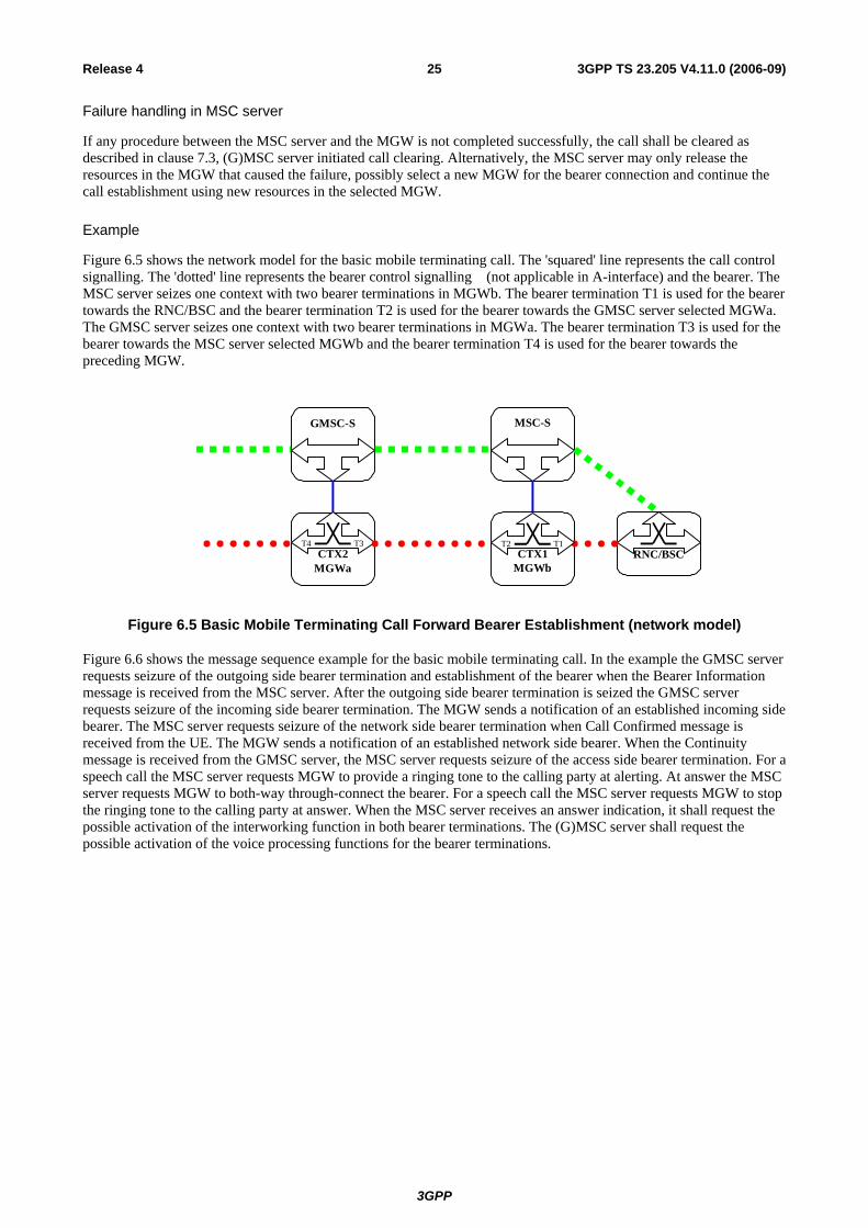
3GPP
3GPP TS 23.205 V4.11.0 (2006-09)25Release 4
Failure handling in MSC server
If any procedure between the MSC server and the MGW is not completed successfully, the call shall be cleared as described in clause 7.3, (G)MSC server initiated call clearing. Alternatively, the MSC server may only release the resources in the MGW that caused the failure, possibly select a new MGW for the bearer connection and continue the call establishment using new resources in the selected MGW.
Example
Figure 6.5 shows the network model for the basic mobile terminating call. The 'squared' line represents the call control signalling. The 'dotted' line represents the bearer control signalling (not applicable in A-interface) and the bearer. The MSC server seizes one context with two bearer terminations in MGWb. The bearer termination T1 is used for the bearer towards the RNC/BSC and the bearer termination T2 is used for the bearer towards the GMSC server selected MGWa. The GMSC server seizes one context with two bearer terminations in MGWa. The bearer termination T3 is used for the bearer towards the MSC server selected MGWb and the bearer termination T4 is used for the bearer towards the preceding MGW.
MGWbMGWa
GMSC-S MSC-S
RNC/BSCCTX2T4 T3
CTX1T2 T1
Figure 6.5 Basic Mobile Terminating Call Forward Bearer Establishment (network model)
Figure 6.6 shows the message sequence example for the basic mobile terminating call. In the example the GMSC server requests seizure of the outgoing side bearer termination and establishment of the bearer when the Bearer Information message is received from the MSC server. After the outgoing side bearer termination is seized the GMSC server requests seizure of the incoming side bearer termination. The MGW sends a notification of an established incoming side bearer. The MSC server requests seizure of the network side bearer termination when Call Confirmed message is received from the UE. The MGW sends a notification of an established network side bearer. When the Continuity message is received from the GMSC server, the MSC server requests seizure of the access side bearer termination. For a speech call the MSC server requests MGW to provide a ringing tone to the calling party at alerting. At answer the MSC server requests MGW to both-way through-connect the bearer. For a speech call the MSC server requests MGW to stop the ringing tone to the calling party at answer. When the MSC server receives an answer indication, it shall request the possible activation of the interworking function in both bearer terminations. The (G)MSC server shall request the possible activation of the voice processing functions for the bearer terminations.

3GPP
3GPP TS 23.205 V4.11.0 (2006-09)26Release 4
Bearer Establishment
HLR Interrogation
Bearer Establishment
Context (C1) NOTIFY.request (T2)
Context (C1) NOTIFY.reply (T2) 6 Bearer Established
Continuity
Continuity
CALL CONFIRMED
SETUP
Initial Address
Paging + Security
UE RNC/BSC MSC-S MGWbGMSC-S MGWa
Initial Address
Context ($) ADD.request ($)
Context (C1) ADD.reply (T2)
Bearer Information
Context ($) ADD.request ($)
Context (C2) ADD.reply (T3)
Context (C2) NOTIFY.request(T4)
Context (C2) NOTIFY.reply(T4)
1
2
3
4
Bearer Information
Context (C2) ADD.request ($)
Context (C2) ADD.reply (T4)
5
8
7
Prepare Bearer + Change Through-Connection
Establish Bearer +Change Through-Connection
Bearer Established
Prepare Bearer +Change Through-Connection
UP Init
UP Init Ack
UP Init
UP Init Ack
Figure 6.6/1 Basic Mobile Terminating Call, Forward Bearer Establishment (message sequence chart)

3GPP
3GPP TS 23.205 V4.11.0 (2006-09)27Release 4
13
UE RNC/BSC MSC-S MGWbGMSC-S MGWa
Context (C1) ADD.request (T1)
Context (C1) ADD.reply (T1)
ASSIGNMENT REQUEST
ASSIGNMENT COMPL
Reserve Circuit + Change Through-Connection
GSM:
Context (C1) MOD.request ( T2)
Context (C1) MOD.reply (T2)
Context (C1) ADD.request ($)
Context (C1) ADD.reply (T1)
RAB ASSIGNMENT REQ
RAB ASSIGNMENT COMPL
Bearer Establish. and Iu UP Initializa.
Address CompleteALERTING
Address Complete Context (C1) MOD.request ( T2)
Context (C1) MOD.reply (T2)
CONNECT
Answer
Context (C1) MOD.request ( T1)
Context (C1) MOD.reply (T1)
9
11
12
Prepare Bearer + Change Through-Connection
Send Tone (start providing a ringing tone for a speech call)
UMTS:
10
Change Through-Connection + Activate Inter-Working Function (when applicable) + Activate Voice Processing Function (when applicable)
Stop Tone (stop providing a ringing tone for speech call) + Activate Interworking Function (when applicable) + Activate Voice Processing Function (when applicable)
Answer
Context (C2) MOD.request ( T4)
Context (C2) MOD.reply (T4)
Activate Voice Processing Function (when applicable)
Context (C2) MOD.request ( T3)
Context (C2) MOD.reply (T3)
Activate Voice Processing Function (when applicable)
Figure 6.6/2 Basic Mobile Terminating Call, Forward Bearer Establishment (message sequence chart continue)

3GPP
3GPP TS 23.205 V4.11.0 (2006-09)28Release 4
6.2.2 Backward bearer establishment The basic mobile terminating call shall be established in accordance with 3GPP TS 23.108 [4]. The following paragraphs describe the additional requirements for the bearer independent CS core network. If out-of-band transcoder control is applied for a speech call, it shall be performed in accordance with 3GPP TS 23.153 [3].
6.2.2.1 GMSC server
MGW selection
The GMSC server shall select an MGW for the bearer connection before it performs the incoming side bearer establishment or the outgoing side bearer establishment. This happens before sending the IAM. If the GMSC server received an MGW-id from the preceding node, it may use this for the MGW selection (bullet 1 in figure 6.8).
NOTE 1: As an implementation option, if there is no need for the GMSC server to manipulate the bearer, the GMSC server may perform call control signalling without any associated MGW. In that case the bearer related information shall be provided transparently through the GMSC server.
Outgoing side bearer establishment
The GMSC server shall either select preferred bearer characteristics or requests the MGW to select and provide the bearer characteristics for the outgoing side bearer connection before it sends the IAM. The GMSC server requests the MGW to prepare for the outgoing side bearer establishment using the Prepare Bearer procedure. The GMSC server requests the MGW to provide a bearer address and a binding reference, and provides the MGW with the preferred bearer characteristics or requests the MGW to select and provide the bearer characteristics (bullet 3 in figure 6.8). After the MGW has replied with the bearer address and the binding reference, the GMSC server sends the IAM to the succeeding node.
Initial addressing
The GMSC server shall indicate in the IAM that backward bearer establishment is to be used. The GMSC server shall also indicate in the IAM that the Continuity message will follow if either of the following conditions is satisfied before sending the IAM:
1. The incoming IAM indicated that the Continuity message will follow, but no Continuity message has been received, or
2. The GMSC server selected an MGW, but a notification of successful bearer establishment on the incoming side has not been received from the MGW.
The GMSC server shall provide the bearer characteristics to the succeeding node in the IAM. The MGW-id may also be provided in the IAM (bullet 4 in figure 6.8).
Incoming side bearer establishment
The GMSC server requests the MGW to establish a bearer to the given destination MGW and to notify when the bearer is established using the Establish Bearer procedure. The GMSC server provides the MGW with the bearer address, the binding reference and the bearer characteristics that were received from the preceding node in the IAM (bullet 1 in figure 6.8).
NOTE 2: The incoming side bearer establishment may take place either before or after HLR interrogation.
Framing protocol initialisation
In 3GPP CS CN speech and data shall be carried using the Iu/Nb User Plane Protocol. The specification for the Iu UP protocol is defined in [20] and the Nb UP Protocol in [7] and [21]. The Iu/Nb UP Protocol is established through the CN in a forward direction. This is established independently of the bearer establishment direction. The MGW derives the forward direction from information sent by the MSC server within the Establish Bearer and Prepare Bearer procedures [6]. The notification of bearer establishment shall not be sent until the Iu/Nb UP has been initialised
3GPP
3GPP TS 23.205 V4.11.0 (2006-09)29Release 4
Through-Connection
During the Prepare Bearer and Establish Bearer procedures, the GMSC server will use the Change Through-Connection procedure to request the MGW to both-way through-connect the bearer termination (bullet 1 and bullet 3 in figure 6.8).
Confirmation of bearer establishment
If the IAM which was sent to the succeeding node indicated that the Continuity message will follow, the Continuity message shall be sent when both of the following conditions are satisfied:
1. Either:
a. The incoming IAM indicated that the Continuity message will follow, and a Continuity message has been received from the preceding node, or
b. The incoming IAM did not indicate that the Continuity message will follow;
2. Either:
a. The GMSC server has selected an MGW, and a notification of successful bearer establishment in the incoming side has been received from the MGW (bullet 2 in figure 6.8), or
b. MGW selection is not requiered for this call.
Voice Processing function
A voice processing function located on the MGW may be used to achieve desired acoustic quality on the bearer terminations. The (G)MSC server shall request the activation of voice processing functions in the bearer terminations. For non-speech calls, the GMSC server has the ability to instruct the MGW to disable the voice processing functions (bullet 12 in figure 6.8). The voice activation request from the GMSC server to MGWa may be issued as soon as bullet 4 in figure 6.8, and may be issued as late as bullet 12 in figure 6.8 as illustrated.
Failure handling in GMSC server
If any procedure between the MSC server and the MGW is not completed successfully or the GMSC server receives a Bearer Released procedure from the MGW, the call shall be cleared as described in clause 7.3, (G)MSC server initiated call clearing or in clause 7.4, MGW initiated call clearing. Alternatively, the GMSC server may only release the resources in the MGW that caused the failure, possibly select a new MGW for the bearer connection and continue the call establishment using new resources in the selected MGW.
6.2.2.2 MSC server
Paging
If the network side bearer establishment is delayed whilst the paging procedure is completed, the MSC server starts the Start_Bearer_Establishment timer when the paging procedure is started. The Start_Bearer_Establishment timer is stopped when the paging procedure is completed, or optionally when the Call Confirmed message is received in accordance with 3GPP TS 23.153 [3]. If the Start_Bearer_Establishment timer expires, the MSC server starts the network side bearer establishment.
Call setup
The MSC server indicates to the UE in the SETUP message that early access bearer assignment is used in order to establish the bearer end-to-end before the UE starts alerting. The MSC server indicates to the UE in the SETUP message that early access bearer assignment is used, if and only if, either of the following conditions are satisfied before sending the SETUP message (bullet 5 in figure 6.8):
1. If the IAM indicated that the Continuity message will follow, but no Continuity message has been received.
2. A notification of successful bearer establishment in the network side has not been received from the MGW.

3GPP
3GPP TS 23.205 V4.11.0 (2006-09)30Release 4
MGW selection
The MSC server shall select an MGW for the bearer connection before it performs the network side bearer establishment or the access bearer assignment. This happens at latest after the UE has sent the Call Confirmed message. If the MSC server received an MGW-id from the preceding node, it may use this for the MGW selection (bullet 6 in figure 6.8).
Network side bearer establishment
The MSC server requests the MGW to establish a bearer to the given destination MGW and to notify when the bearer is established using the Establish Bearer procedure. The MSC server provides the MGW with the bearer address, the binding reference and the bearer characteristics that were received from the preceding node in the IAM (bullet 6 in figure 6.8).
Access bearer assignment
The access bearer assignment may be started when both of the following conditions are satisfied:
1. Either:
a. The incoming IAM indicated that the Continuity message will follow, and a Continuity message has been received from the preceding node, or
b. The incoming IAM did not indicate that the Continuity message will follow;
2. A notification of successful bearer establishment in the network side has been received from the MGW (bullet 7 in figure 6.8).
The MSC server shall select bearer characteristics for the access bearer.
For the access bearer assignment in UTRAN the MSC server requests the MGW to prepare for the access bearer establishment using the Prepare Bearer procedure. The MSC server requests the MGW to provide a bearer address and a binding reference, provides the MGW with the bearer characteristics and requests notification that the bearer can be modified. For speech calls, the MSC server shall provide the MGW with the speech coding information for the bearer. For a non-speech call the MSC server also provides the MGW with a PLMN Bearer Capability [4]. After the MGW has replied with the bearer address and the binding reference the MSC server requests the access bearer assignment using the provided bearer address and the binding reference (bullet 8 in figure 6.8) ) in accordance with 3GPP TS 25.413 [26]. The MSC shall only be notified by the MGW using the Bearer Modification Support procedure if the existing link characteristics of the access bearer can be modified at a later stage, see subclause 13.18.1..
For GERAN, before the MSC server starts the access bearer assignment, the MSC server uses the Reserve Circuit procedure to seize a TDM circuit. For a non-speech call the MSC server also provides the MGW with a PLMN Bearer Capability [4] and a GSM channel coding. After the MGW has replied the TDM circuit seizure the MSC server requests access bearer assignment (bullet 9 in figure 6.8) in accordance with 3GPP TS 48.008 [27].
Framing protocol initialisation
In 3GPP CS CN speech and data shall be carried using the Iu/Nb User Plane Protocol. The specification for the Iu UP protocol is defined in [20] and the Nb UP Protocol in [7] and [21]. The Iu/Nb UP Protocol is established through the CN in a forward direction. This is established independently of the bearer establishment direction. The MGW derives the forward direction from information sent by the MSC server within the Establish Bearer and Prepare Bearer procedures [6]. The notification of bearer establishment shall not be sent until the Nb UP has been initialised.
Called party alerting
For a speech call, when the MSC server receives an Alerting message, it requests the MGW to provide a ringing tone to the calling party using the Send Tone procedure (bullet 10 in figure 6.8).
NOTE: Other kind of tones may be provided to the calling party at an earlier stage of the call establishment.
3GPP
3GPP TS 23.205 V4.11.0 (2006-09)31Release 4
Called party answer
For a speech call, when the MSC server receives a Connect message, it requests the MGW to stop providing the ringing tone to the calling party using the Stop Tone procedure (bullet 11 in figure 6.8).
Through-Connection
During any one of the Prepare Bearer, Reserve Circuit and Establish Bearer procedures, the MSC server will use the Change Through-Connection procedure to request the MGW to through-connect the bearer terminations so that the bearer will be not through-connected (bullet 6, and bullet 8 or 9 in figure 6.8).
When the MSC server receives the Connect message, it requests the MGW to both-way through-connect the bearer using the Change Through-Connection procedure (bullet 11 in figure 6.8).
Interworking function
The MGW may use an interworking function that is based on the PLMN Bearer Capability [4] of the bearer termination. The activation of the possible interworking function in both bearer terminations will be requested by the MSC server at reception of the Connect message using the Activate Interworking Function procedure (bullet 11 in figure 6.8).
Codec handling
The MGW may include a speech transcoder based upon the speech coding information provided to each bearer termination.
Voice Processing function
A voice processing function located on the MGW may be used to achieve desired acoustic quality on the bearer terminations. The MSC server shall request the activation of the voice processing functions in the bearer terminations. For non-speech calls, the MSC server has the ability to instruct the MGW to disable the voice processing functions (bullet 11 in figure 6.8).
Failure handling in MSC server
If any procedure between the MSC server and the MGW is not completed successfully or the MSC server receives a Bearer Released procedure from the MGW, the call shall be cleared as described in clause 7.3, (G)MSC server initiated call clearing or in clause 7.4, MGW initiated call clearing. Alternatively, the MSC server may only release the resources in the MGW that caused the failure, possibly select a new MGW for the bearer connection and continue the call establishment using new resources in the selected MGW.
Example
Figure 6.7 shows the network model for the basic mobile terminating call. The 'squared' line represents the call control signalling. The 'dotted' line represents the bearer control signalling (not applicable in A-interface) and the bearer. The MSC server seizes one context with two bearer terminations in MGWb. The bearer termination T1 is used for the bearer towards the RNC/BSC and the bearer termination T2 is used for the bearer towards the GMSC server selected MGWa. The GMSC server seizes one context with two bearer terminations in MGWa. The bearer termination T3 is used for the bearer towards the MSC server selected MGWb and the bearer termination T4 is used for the bearer towards the preceding MGW.

3GPP
3GPP TS 23.205 V4.11.0 (2006-09)32Release 4
MGWbMGWa
GMSC-S MSC-S
RNC/BSCCTX2T4 T3
CTX1T2 T1
Figure 6.7 Basic Mobile Terminating Call, Backward Bearer Establishment (network model)
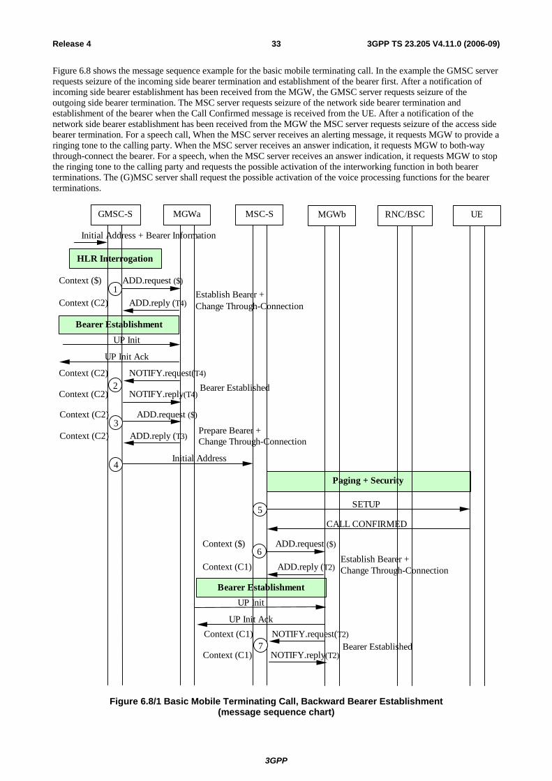
3GPP
3GPP TS 23.205 V4.11.0 (2006-09)33Release 4
Figure 6.8 shows the message sequence example for the basic mobile terminating call. In the example the GMSC server requests seizure of the incoming side bearer termination and establishment of the bearer first. After a notification of incoming side bearer establishment has been received from the MGW, the GMSC server requests seizure of the outgoing side bearer termination. The MSC server requests seizure of the network side bearer termination and establishment of the bearer when the Call Confirmed message is received from the UE. After a notification of the network side bearer establishment has been received from the MGW the MSC server requests seizure of the access side bearer termination. For a speech call, When the MSC server receives an alerting message, it requests MGW to provide a ringing tone to the calling party. When the MSC server receives an answer indication, it requests MGW to both-way through-connect the bearer. For a speech, when the MSC server receives an answer indication, it requests MGW to stop the ringing tone to the calling party and requests the possible activation of the interworking function in both bearer terminations. The (G)MSC server shall request the possible activation of the voice processing functions for the bearer terminations.
Bearer Establishment
Bearer Establishment
HLR Interrogation
CALL CONFIRMED
SETUP
Initial Address
Paging + Security
UE RNC/BSCMSC-S MGWbGMSC-S MGWa
Initial Address + Bearer Information
Context ($) ADD.request ($)
Context (C1) ADD.reply (T2)
Context (C2) ADD.request ($)
Context (C2) ADD.reply (T3)
Context (C2) NOTIFY.request(T4)
Context (C2) NOTIFY.reply(T4)
4
5
6
3
Context ($) ADD.request ($)
Context (C2) ADD.reply (T4) 1
2
Context (C1) NOTIFY.request(T2)
Context (C1) NOTIFY.reply(T2) 7
Establish Bearer + Change Through-Connection
Prepare Bearer +Change Through-Connection
Establish Bearer +Change Through-Connection
Bearer Established
Bearer Established
UP Init
UP Init Ack
UP Init
UP Init Ack
Figure 6.8/1 Basic Mobile Terminating Call, Backward Bearer Establishment (message sequence chart)

3GPP
3GPP TS 23.205 V4.11.0 (2006-09)34Release 4
UE RNC/BSC MSC-S MGWbGMSC-
S MGWa
Address CompleteALERTING
Address CompleteContext (C1) MOD.request ( T2)
Context (C1) MOD.reply (T2)
CONNECT
Answer
Context (C1) MOD.request ( T2)
Context (C1) MOD.reply (T2)
Answer
10
Context (C1) MOD.request ( T1)
Context (C1) MOD.reply (T1) 11
Send Tone (start providing a ringing tone for a speech call)
Change Through-Connection + Activate Interworking Function (when applicable) + Activate Voice Processing Function (when applicable) Stop Tone (stop providing a ringing tone for speech call) + Activate Interworking Function (when applicable) + Activate Voice Processing Function (when applicable)
Context (C2) MOD.request ( T4)
Context (C2) MOD.reply (T4)
Context (C2) MOD.request ( T3)
Context (C2) MOD.reply (T3) 12
Activate Voice Processing Function(when applicable)
Activate Voice Processing Function (when applicable)
Context (C1) ADD.request (T1)
Context (C1) ADD.reply (T1)
ASSIGNMENT REQUEST
ASSIGNMENT COMPL
Reserve Circuit + Change Through-Connection
GSM:
Context (C1) ADD.request ($)
Context (C1) ADD.reply (T1)
RAB ASSIGNMENT REQ
RAB ASSIGNMENT COMPL
Bearer Establish. and Iu UP Initializa.
8 Prepare Bearer + Change Through-Connection
UMTS:
9
Figure 6.8/2 Basic Mobile Terminating Call, Backward Bearer Establishment (message sequence chart continue)

3GPP
3GPP TS 23.205 V4.11.0 (2006-09)35Release 4
7 Call Clearing NOTE: All message sequence charts in this clause are examples. All valid call establishment message sequences
can be derived from the example message sequences and associated message pre-conditions.
7.1 Network Initiated The terms "incoming" and "outgoing" in the following text refers to the direction of propagation of the Release message, not to the direction of establishing the original call.
7.1.1 GMSC server
Call clearing from the incoming side
Once the Release message has been received from the preceding node, the GMSC server releases any MGW allocated resources for the incoming side. If any resources were seized in the MGW, the GMSC server shall use the Release Bearer, Change Through-Connection and Release Termination procedures to indicate to the MGW to remove the incoming side bearer termination and that the bearer can be released towards the preceding MGW. After the resources in the MGW are released the GMSC server sends the Release Complete message to the preceding node.
Call clearing to the outgoing side
The GMSC server sends the Release message to the succeeding node. Once the succeeding node has sent the Release Complete message, the GMSC server releases any MGW allocated resources for the outgoing side. If any resources were seized in the MGW, the GMSC server shall use the Release Bearer, Change Through-Connection and Release Termination procedures to indicate to the MGW to remove the outgoing side bearer termination and that the bearer can be released towards the succeeding MGW.
7.1.2 MSC server The network initiated call clearing shall be performed in accordance with 3GPP TS 23.108 [18]. The following paragraphs describe the additional requirements for the bearer independent CS core network.
Call clearing from the network side
Once the Release message has been received from the preceding/succeeding node, the MSC server releases any MGW allocated resources for the network side. If any resources were seized in the MGW, the MSC server shall use the Release Bearer, Change Through-Connection and Release Termination procedures to indicate to the MGW to remove the network side bearer termination and that the bearer can be released towards the preceding/succeeding MGW. After the resources in the MGW are released the MSC server sends the Release Complete message to the preceding/succeeding node (bullet 1 in figure 7.2).
Call clearing to the UE
The MSC server initiates call clearing towards the UE and requests release of the associated radio resources as described in 3GPP TS 23.108[18]. Once the call clearing and the release of the associated radio resources have been completed, the MSC server releases any MGW allocated resources for the access side. If any resources were seized in the MGW, the MSC server uses the Release Termination procedure to requests the MGW to remove the access side bearer termination (bullet 2 or bullet 3 in figure 7.2).
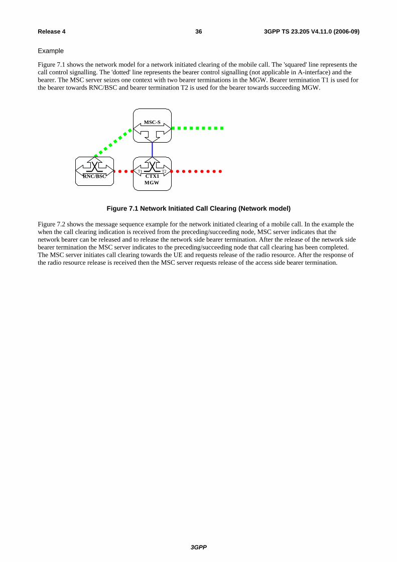
3GPP
3GPP TS 23.205 V4.11.0 (2006-09)36Release 4
Example
Figure 7.1 shows the network model for a network initiated clearing of the mobile call. The 'squared' line represents the call control signalling. The 'dotted' line represents the bearer control signalling (not applicable in A-interface) and the bearer. The MSC server seizes one context with two bearer terminations in the MGW. Bearer termination T1 is used for the bearer towards RNC/BSC and bearer termination T2 is used for the bearer towards succeeding MGW.
MGW
MSC-S
CTX1T1 T2
RNC/BSC
Figure 7.1 Network Initiated Call Clearing (Network model)
Figure 7.2 shows the message sequence example for the network initiated clearing of a mobile call. In the example the when the call clearing indication is received from the preceding/succeeding node, MSC server indicates that the network bearer can be released and to release the network side bearer termination. After the release of the network side bearer termination the MSC server indicates to the preceding/succeeding node that call clearing has been completed. The MSC server initiates call clearing towards the UE and requests release of the radio resource. After the response of the radio resource release is received then the MSC server requests release of the access side bearer termination.
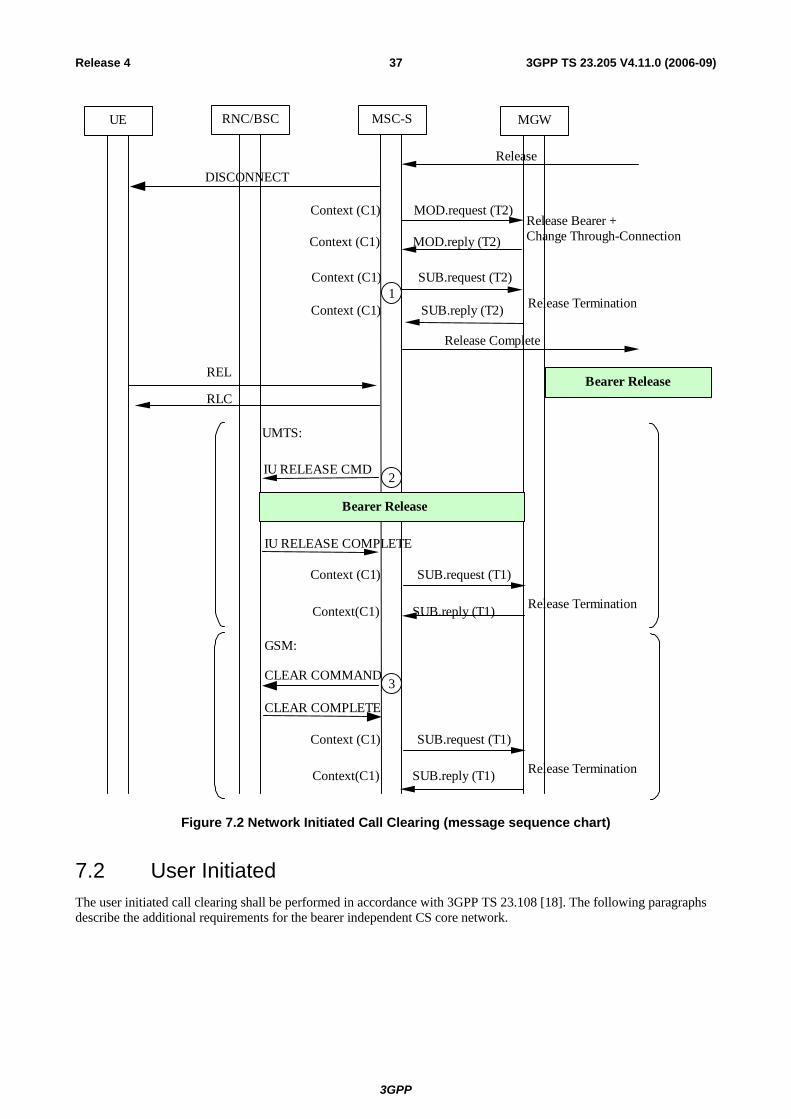
3GPP
3GPP TS 23.205 V4.11.0 (2006-09)37Release 4
GSM:
UMTS:
Release Termination
CLEAR COMPLETE
CLEAR COMMAND
Context(C1) SUB.reply (T1)
Context (C1 ) SUB.request (T1)
3
Release Termination
Release Bearer + Change Through-Connection Context (C1 ) MOD.reply (T2)
Context (C1 ) MOD.request (T2)
Release Termination
IU RELEASE COMPLETE
REL
RLC
DISCONNECT
IU RELEASE CMD
Context(C1) SUB.reply (T1)
Context (C1 ) SUB.request (T1)
Release
Context (C1 ) SUB.request (T2)
Context (C1 ) SUB.reply (T2)
Release Complete
UE RNC/BSC MSC-S MGW
Bearer Release
1
2
Bearer Release
Figure 7.2 Network Initiated Call Clearing (message sequence chart)
7.2 User Initiated The user initiated call clearing shall be performed in accordance with 3GPP TS 23.108 [18]. The following paragraphs describe the additional requirements for the bearer independent CS core network.

3GPP
3GPP TS 23.205 V4.11.0 (2006-09)38Release 4
7.2.1 Void
7.2.2 MSC server
Call clearing from the UE
The UE initiated call clearing is performed and the release of the associated radio resources is performed as described in 3GPP TS 23.108 [18]. Once the call clearing and the associated radio resources release have been completed, the MSC server releases any MGW allocated resources for the access side. If any resources were seized in the MGW the MSC server uses the Release Termination procedure to requests the MGW to remove the access side bearer termination (bullet 1 or bullet 2 in figure 7.4).
Call clearing to the network side
The MSC server sends the Release message to the preceding/succeeding node. Once the preceding/succeeding node has sent the Release Complete, the MSC server releases any MGW allocated resources for the network side. If any resources were seized in the MGW server shall use the Release Bearer, Change Through-Connection and Release Termination procedures to indicate to the MGW to remove the network side bearer termination and that the bearer can be released towards the preceding/succeeding MGW (bullet 3 in figure 7.4).
Example
Figure 7.3 shows the network model for a user initiated clearing of a mobile call. The 'squared' line represents the call control signalling. The 'dotted' line represents the bearer control signalling (not applicable in A-interface) and the bearer. The MSC server seizes one context with two bearer terminations in the MGW. Bearer termination T1 is used for the bearer towards RNC/BSC and bearer termination T2 is used for the bearer towards succeeding MGW.
MGW
MSC-S
CTX1T1 T2
RNC/BSC
Figure 7.3 User Initiated Call Clearing (Network model)
Figure 7.4 shows the message sequence example for the user initiated clearing of a mobile call. In the example the UE initiates call clearing towards the MSC server and the MSC server requests release of the radio resource. After the response of the radio resource release is received the MSC server requests the release of the access side bearer termination. The MSC server initiates call clearing towards the preceding/succeeding node. Once the preceding/succeeding node has indicated that call clearing has been completed, the MSC server indicates that the network bearer can be released and to release the network side bearer termination.

3GPP
3GPP TS 23.205 V4.11.0 (2006-09)39Release 4
Release Complete
GSM:
UMTS:
CLEAR COMPLETE
CLEAR COMMAND
Release Termination Context(C1) SUB.reply (T1)
Context (C1 ) SUB.request (T1)
2
Release Termination
IU RELEASE COMPLETE
IU RELEASE CMD
Context(C1) SUB.reply (T1)
Context (C1 ) SUB.request (T1)
1
Release Bearer + Change Through-Connection Context (C1 ) MOD.reply (T2)
Context (C1 ) MOD.request (T2)
Release Termination
REL
RLC
DISCONNECT
Context (C1 ) SUB.reply (T2)
Context (C1 ) SUB.request (T2)
Release
UE RNC/BSC MSC-S MGW
Bearer Release
3
Bearer Release
Figure 7.4 User Initiated Call Clearing (message sequence chart)
7.3 (G)MSC server Initiated The following paragraphs describe the additional requirements for (G)MSC server initiated call clearing in the bearer independent CS core network.

3GPP
3GPP TS 23.205 V4.11.0 (2006-09)40Release 4
7.3.1 GMSC server
Call clearing to the destination side
If the call is already established towards the destination, call clearing is performed as described in clause 7.1.1, call clearing to the outgoing side.
Call clearing to the originating side
The call clearing to the originating side is performed as described in clause 7.1.1, call clearing to the outgoing side.
7.3.2 MSC server
Call clearing to the UE
The call clearing to the UE is performed as described in clause 7.1.2, call clearing to the UE (bullet 1 and bullet 2 in figure 7.6).
Call clearing to the network side
If the call is already established towards the network side, the call clearing to the network side is performed as described in clause 7.2.2, call clearing to the network side (bullet 3 in figure 7.6).
Example
Figure 7.5 shows the network model for the MSC server initiated clearing of the mobile call. The 'squared' line represents the call control signalling. The 'dotted' line represents the bearer control signalling (not applicable in A-interface) and the bearer. The MSC server seizes one context with two bearer terminations in the MGW. Bearer termination T1 is used for the bearer towards RNC/BSC and bearer termination T2 is used for the bearer towards succeeding MGW.
MGW
MSC-S
CTX1T1 T2
RNC/BSC
Figure 7.5 MSC Server Initiated Call Clearing (Network model)
Figure 7.6 shows the message sequence example for the MSC server initiated clearing of a mobile call. In the example the MSC server initiates call clearing of the network side and the access side. After the call clearing towards the UE and the release of the radio resource have been completed the MSC server requests release of the access side bearer termination. Once the preceding/succeeding node has indicated that call clearing has been completed, the MSC server indicates that the network bearer can be released and to release the network side bearer termination.
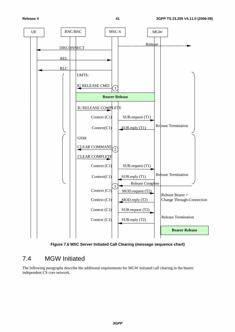
3GPP
3GPP TS 23.205 V4.11.0 (2006-09)41Release 4
Release Bearer + Change Through-Connection Context (C1 ) MOD.reply (T2)
Context (C1 )
Release Termination Context (C1 ) SUB.reply (T2)
Context (C1 ) SUB.request (T2)
Bearer Release
Release Complete
GSM:
UMTS:
CLEAR COMPLETE
CLEAR COMMAND
Release Termination Context(C1) SUB.reply (T1)
Context (C1 ) SUB.request (T1)
2
Release Termination
IU RELEASE COMPLETE
IU RELEASE CMD
Context(C1) SUB.reply (T1)
Context (C1 ) SUB.request (T1)
1
REL
RLC
DISCONNECT Release
UE RNC/BSC MSC-S MGW
3
Bearer Release
MOD.request (T2)
Figure 7.6 MSC Server Initiated Call Clearing (message sequence chart)
7.4 MGW Initiated The following paragraphs describe the additional requirements for MGW initiated call clearing in the bearer independent CS core network.

3GPP
3GPP TS 23.205 V4.11.0 (2006-09)42Release 4
7.4.1 GMSC server
Bearer released on the destination side
After the GMSC server has received the Bearer Released procedure from the MGW, it shall send the Release message to the succeeding node. Once the succeeding node has sent the Release Complete message, the GMSC server releases any MGW allocated resources for the destination side. The GMSC server uses the Release Termination procedure to request the MGW to remove the destination side bearer termination.
The call clearing to the incoming side is performed as described in clause 7.1.1.2, call clearing to the outgoing side.
Bearer released on the originating side
After the GMSC server has received the Bearer Released procedure from the MGW, the GMSC server sends the Release message to the preceding node. Once the preceding node has sent the Release Complete message, the GMSC server releases any MGW allocated resources for the originating side. The GMSC server uses the Release Termination procedure to request the MGW to remove the originating side bearer termination.
If the call is already established towards the destination side, call clearing to the destination side is performed as described in clause 7.1.1.2, call clearing to the outgoing side.
7.4.2 MSC server
Bearer released on the access side
After the MSC server has received the Bearer Released procedure from the MGW, the MSC server initiates the call clearing towards the UE and requests release of the allocated radio resources as described in 3GPP TS 23.108 [18]. Once the call clearing and the radio resources release have been completed, the MSC server releases any MGW allocated resources for the access side. The MSC server uses the Release Termination procedure to request the MGW to remove the access side bearer termination.
If the call is already established towards the network side, call clearing to the network side is performed as described in clause 7.2, call clearing to the network side.
Bearer released on the network side
After the MSC server has received the Bearer Released procedure from the MGW, the MSC server sends the Release message to the preceding/succeeding node. Once the preceding/succeeding node has sent the Release Complete message, the MSC server releases any MGW allocated resources for the network side. The MSC server uses the Release Termination procedure to request the MGW to remove the network side bearer termination (bullet 1 and bullet 2 in figure 7.8).
Call clearing to the UE is performed as described in clause 7.1.2.2, call clearing to the UE (bullet 3 in figure 7.8).
Example
Figure 7.7 shows the network model for an MGW initiated clearing of a mobile call. The 'squared' line represents the call control signalling. The 'dotted' line represents the bearer control signalling (not applicable in A-interface) and the bearer. The MSC server seizes one context with two bearer terminations in the MGW. Bearer termination T1 is used for the bearer towards RNC/BSC and bearer termination T2 is used for the bearer towards succeeding MGW.

3GPP
3GPP TS 23.205 V4.11.0 (2006-09)43Release 4
MGW
MSC-S
CTX1T1 T2
RNC/BSC
Figure 7.7 MGW Initiated Call Clearing (Network model)
Figure 7.8 shows the message sequence example for the MGW initiated clearing of a mobile call. After the MSC server is notified that the MGW has released the network side bearer, the MSC server initiates call clearing of the network side and the access side. After the call clearing towards the UE and the radio resource release have been completed the MSC server requests release of the access side bearer termination. Once the preceding/succeeding node has indicated that call clearing has been completed, the MSC server requests the release of the network side bearer termination.

3GPP
3GPP TS 23.205 V4.11.0 (2006-09)44Release 4
Release Termination Context (C1) SUB.reply (T2)
Context (C1) SUB.request (T2)
Release Complete3
GSM:
CLEAR COMPLETE
CLEAR COMMAND
Release TerminationContext(C1) SUB.reply (T1)
Context (C1) SUB.request (T1)
2
Release Termination
IU RELEASE COMPLETE
IU RELEASE CMD
Context(C1) SUB.reply (T1)
Context (C1) SUB.request (T1)
1
Context (C1) NOTIFY.reply (T2)Bearer Released
Context (C1) NOTIFY.request (T2)
REL
RLC
DISCONNECTRelease
UE RNC/BSC MSC-S MGW
UMTS:
Bearer Release
Figure 7.8 MGW Initiated Call Clearing (message sequence chart)
8 Handover/Relocation NOTE: All message sequence charts in this clause are examples. All valid handover/relocation message
sequences can be derived from the example message sequences and associated message pre-conditions.

3GPP
3GPP TS 23.205 V4.11.0 (2006-09)45Release 4
8.1 UMTS to UMTS
8.1.1 Intra-MSC SRNS Relocation The procedures specified in 3GPP TS 23.009 [8] for 'Intra-3G_MSC SRNS Relocation' shall be followed. The following paragraphs describe the additional requirements for the bearer independent CS core network.
Relocation Required
When the Relocation Required message is received, the MSC server requests the MGW to provide a binding reference and a bearer address, using the Prepare Bearer procedure. For speech calls, the MSC server shall provide the MGW with the speech coding information for the bearer. For non-speech calls the MSC server also provides the MGW with the same PLMN Bearer Capability [4] as was provided at the last access bearer assignment. The MSC server uses the Change Flow Direction Procedure to request the MGW to set the Handover Device to initial state. The MSC server sends the Relocation Request message, containing the bearer address and the binding reference, to RNC-B (bullet 1 in figure 8.2/1).
Relocation Command/Relocation Detect
When the MSC server sends the Relocation Command message or alternatively if it receives the Relocation Detect message, the MSC server uses the Change Flow Direction procedure to request the MGW to set the Handover Device to intermediate state (bullet 2 in figure 8.2/1).
Relocation Complete
When the MSC server receives the Relocation Complete message, it requests RNC-A to release the IU. The MSC server also requests the MGW to set the Handover Device to its final state by removing the bearer termination towards RNC-A, using the Release Termination procedure (bullet 3 in figure 8.2/2).
Interworking function
The interworking function used by the MGW before relocation will also be used after relocation.
Codec handling
The MGW may include a speech transcoder based upon the speech coding information provided to each bearer termination.
Voice Processing function
After relocation, the MGW may continue or modify voice-processing function(s) provided to each bearer termination.
Handling of multiple bearers (multicall)
If the UE is engaged with multiple bearers all procedures related to the handling of bearers and terminations described for the relocation of a single bearer shall be repeated for each bearer.
Failure Handling in MSC server
When a procedure between the MSC server and the MGW fails the MSC server shall handle the failure as an internal error in accordance with 3GPP TS 23.009 [8] and 3GPP TS 29.010 [23]. If MGW resources have been already seized at the target access side then the resources shall be released using the Release Termination procedure. If the call is to be cleared, then it shall be handled as described in clause 7.3.
Example
Figure 8.1 shows the network model for the Intra-MSC SRNS Relocation. The 'squared' line represents the call control signalling. The 'dotted' line represents the bearer control signalling and the bearer. The bearer termination T1 is used for the bearer towards RNC-A, bearer termination T3 is used for the bearer towards RNC-B and the bearer termination T2 is used for the bearer towards the succeeding/preceding MGW.

3GPP
3GPP TS 23.205 V4.11.0 (2006-09)46Release 4
MSC-S
CTX1T1 T2
MGWRNC A
Before Relocation
MSC-S
RNC A
RNC B
CTX1MGW
T1 T2
T3
During Relocation
MSC-S
CTX1T3 T2
MGWRNC B
After Relocation
Figure 8.1 Intra-MSC SRNS Relocation (network model)
Figure 8.2 shows the message sequence example for the Intra-MSC SRNS Relocation. It is assumed that the Handover Device is located in the MGW, which has been selected for the call establishment by the MSC server. The MSC server controls the call and the mobility management. It is also assumed that only one bearer has been established towards RNC-A. In the example the MSC server requests seizure of RNC-B side bearer termination with specific flow directions. The MSC server orders the establishment of the bearer by sending Relocation Request towards RNC-B. When the relocation is detected in RNC-B the MSC server requests to change the flow directions between the terminations within the context. When the MSC server receives a Relocation Complete indication from RNC-B it orders RNC-A to release the IU. This action causes release of the bearer between the RNC and the MGW. Finally the MSC server requests the MGW to release RNC-A side bearer termination.
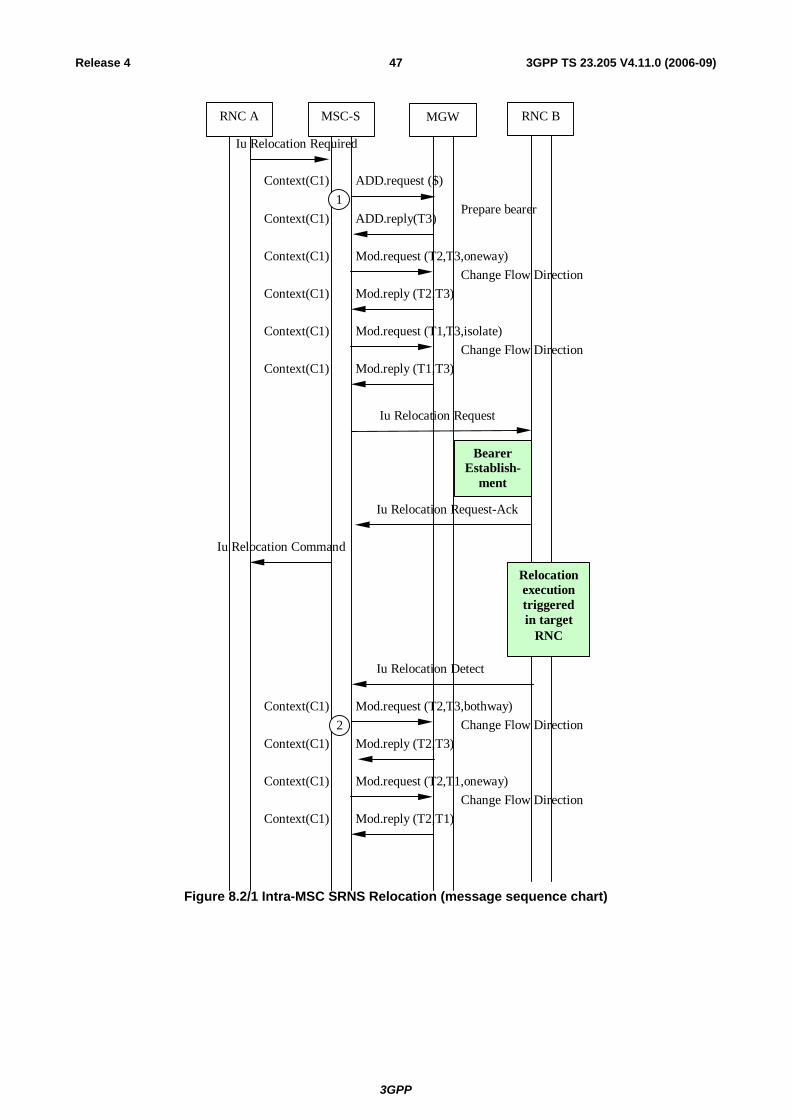
3GPP
3GPP TS 23.205 V4.11.0 (2006-09)47Release 4
Context(C1) ADD.reply(T3)
Context(C1) ADD.request ($)
RNC BMSC-S MGWRNC A
Iu Relocation Required
Iu Relocation Request
BearerEstablish-
ment
Iu Relocation Request-Ack
Iu Relocation Command
Relocationexecutiontriggeredin target
RNC
Iu Relocation Detect
Context(C1) Mod.request (T2,T3,bothway)
Context(C1) Mod.reply (T2,T3)
Context(C1) Mod.request (T2,T1,oneway)
Context(C1) Mod.reply (T2,T1)
2
1Prepare bearer
Change Flow Direction
Change Flow Direction
Context(C1) Mod.request (T2,T3,oneway)
Context(C1) Mod.reply (T2,T3)Change Flow Direction
Context(C1) Mod.request (T1,T3,isolate)
Context(C1) Mod.reply (T1,T3)Change Flow Direction
Figure 8.2/1 Intra-MSC SRNS Relocation (message sequence chart)
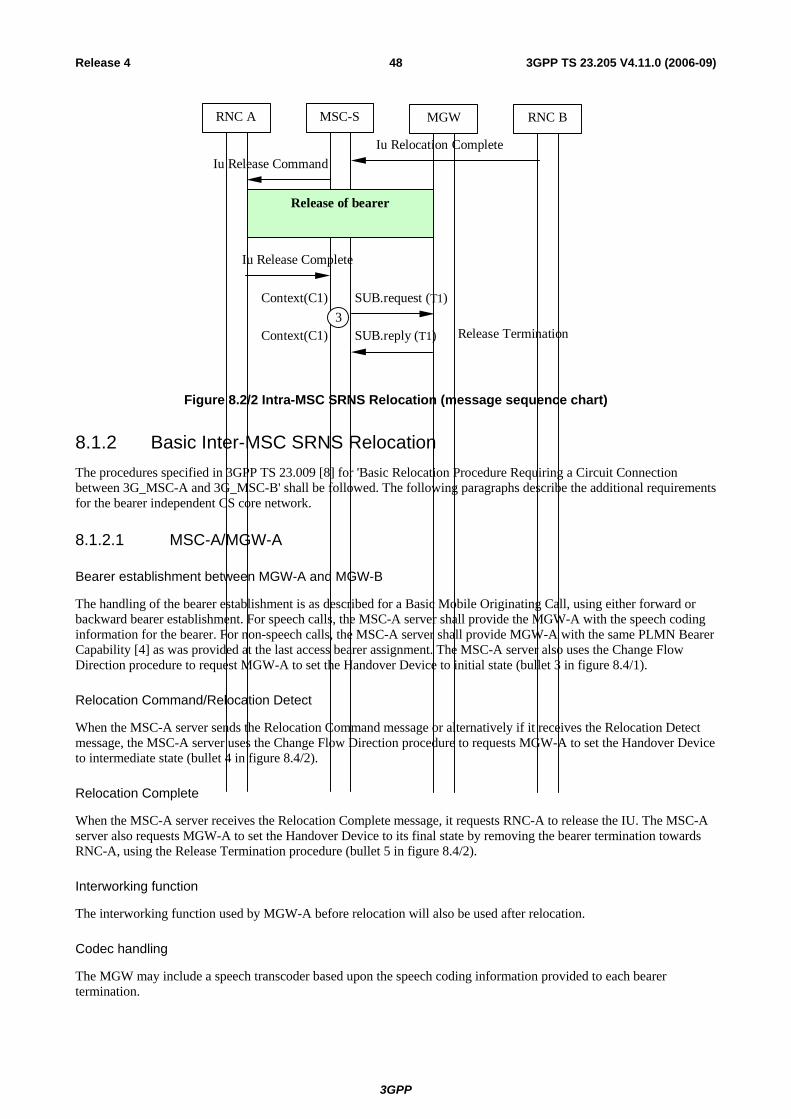
3GPP
3GPP TS 23.205 V4.11.0 (2006-09)48Release 4
RNC A MGW RNC BMSC-S
Iu Relocation CompleteIu Release Command
Iu Release Complete
Context(C1) SUB.request (T1)
Context(C1) SUB.reply (T1) 3
Release Termination
Release of bearer
Figure 8.2/2 Intra-MSC SRNS Relocation (message sequence chart)
8.1.2 Basic Inter-MSC SRNS Relocation The procedures specified in 3GPP TS 23.009 [8] for 'Basic Relocation Procedure Requiring a Circuit Connection between 3G_MSC-A and 3G_MSC-B' shall be followed. The following paragraphs describe the additional requirements for the bearer independent CS core network.
8.1.2.1 MSC-A/MGW-A
Bearer establishment between MGW-A and MGW-B
The handling of the bearer establishment is as described for a Basic Mobile Originating Call, using either forward or backward bearer establishment. For speech calls, the MSC-A server shall provide the MGW-A with the speech coding information for the bearer. For non-speech calls, the MSC-A server shall provide MGW-A with the same PLMN Bearer Capability [4] as was provided at the last access bearer assignment. The MSC-A server also uses the Change Flow Direction procedure to request MGW-A to set the Handover Device to initial state (bullet 3 in figure 8.4/1).
Relocation Command/Relocation Detect
When the MSC-A server sends the Relocation Command message or alternatively if it receives the Relocation Detect message, the MSC-A server uses the Change Flow Direction procedure to requests MGW-A to set the Handover Device to intermediate state (bullet 4 in figure 8.4/2).
Relocation Complete
When the MSC-A server receives the Relocation Complete message, it requests RNC-A to release the IU. The MSC-A server also requests MGW-A to set the Handover Device to its final state by removing the bearer termination towards RNC-A, using the Release Termination procedure (bullet 5 in figure 8.4/2).
Interworking function
The interworking function used by MGW-A before relocation will also be used after relocation.
Codec handling
The MGW may include a speech transcoder based upon the speech coding information provided to each bearer termination.

3GPP
3GPP TS 23.205 V4.11.0 (2006-09)49Release 4
Voice Processing function
Voice processing function(s) provided by MGW-A before relocation, may be modified or disabled by MGW-A after relocation.
Handling of multiple bearers (multicall)
If the UE is engaged with multiple bearers all procedures related to the handling of bearers and terminations described for the relocation of a single bearer shall be repeated for each bearer.
Failure Handling in MSC server
When a procedure between the MSC-A server and MGW-A fails the MSC-A server shall handle the failure as an internal error in accordance with 3GPP TS 23.009 [8] and 3GPP TS 29.010 [23]. If call establishment towards MSC-B has already started then the call towards MSC-B server shall be cleared as described in clause 7.3. If the original call is to be cleared, then it shall be handled as described in clause 7.3.
8.1.2.2 MSC-B/MGW-B
MGW selection
The MSC-B server selects an MGW when it receives Prepare Handover Request message (bullet 1 in figure 8.4/1).
Bearer establishment towards RNC-B
When the MSC-B server has selected MGW-B it requests MGW-B to provide a binding reference and a bearer address, using the Prepare Bearer procedure. For speech calls, the MSC-B server shall provide the MGW-B with the speech coding information for the bearer. The MSC-B server sends the Relocation Request message to the RNC-B containing the bearer addresses and binding references (bullet 2 in figure 8.4/1).
Bearer establishment between MGW-A and MGW-B
The handling of the bearer establishment is as described at Basic Mobile Terminating Call, using either forward or backward bearer establishment.
Codec handling
The MGW may include a speech transcoder based upon the speech coding information provided to each bearer termination.
Voice Processing function
Voice processing function(s) provided by MGW-A before relocation, may be continued or modified by MGW-B after relocation.
Handling of multiple bearers (multicall)
If the UE is engaged with multiple bearers all procedures related to the handling of bearers and terminations described for the relocation of a single bearer shall be repeated for each bearer.
Failure Handling in MSC server
When a procedure between the MSC-B server and MGW-B fails the MSC-B server shall handle the failure as an internal error in accordance with 3GPP TS 23.009 [8] and 3GPP TS 29.010 [23]. If MGW-B resources have been already seized at the target access side then the resources shall be released using the Release Termination procedure. The call from MSC-A server shall be released as described at clause 7.1.
Example
Figure 8.3 shows the network model for the Basic Inter-MSC SRNS Relocation. The 'squared' line represents the call control signalling. The 'dotted' line represents the bearer control signalling and the bearer. In MGW-A the bearer
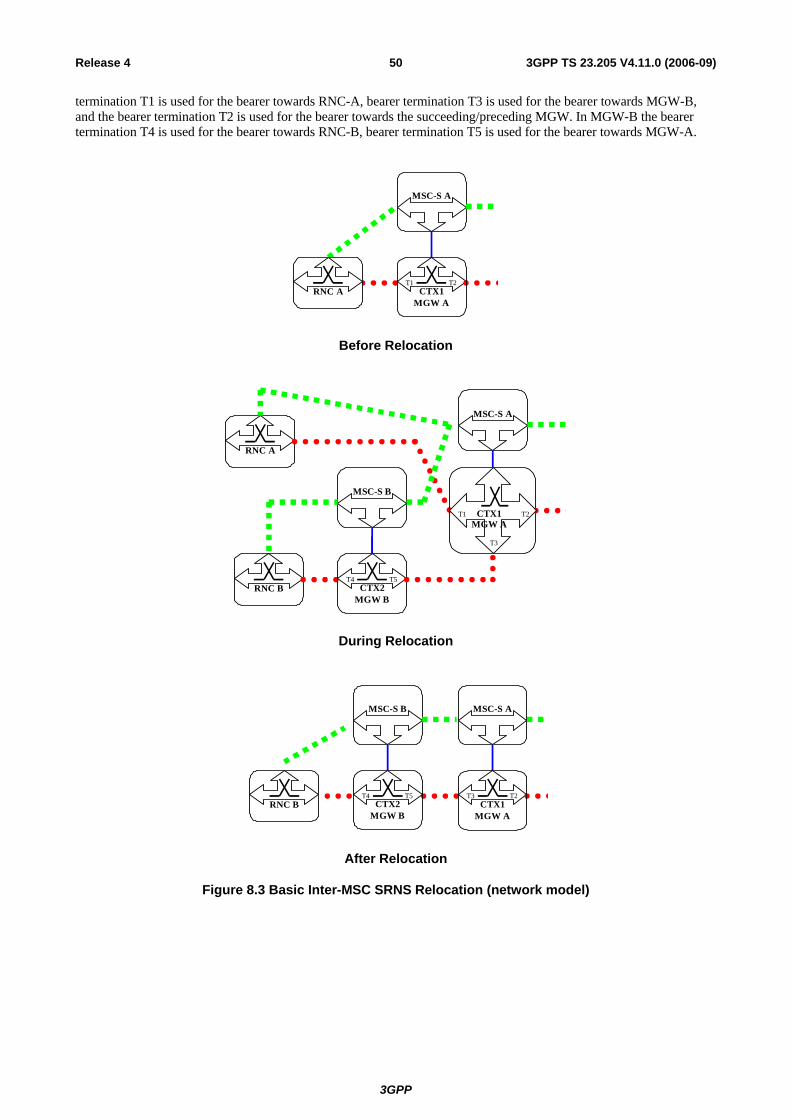
3GPP
3GPP TS 23.205 V4.11.0 (2006-09)50Release 4
termination T1 is used for the bearer towards RNC-A, bearer termination T3 is used for the bearer towards MGW-B, and the bearer termination T2 is used for the bearer towards the succeeding/preceding MGW. In MGW-B the bearer termination T4 is used for the bearer towards RNC-B, bearer termination T5 is used for the bearer towards MGW-A.
MSC-S A
CTX1T1 T2
MGW ARNC A
Before Relocation
MSC-S A
RNC A
CTX1MGW A
T1 T2
T3
RNC B CTX2T4 T5
MGW B
MSC-S B
During Relocation
MSC-S A
CTX1T3 T2
MGW ARNC B CTX2
T4 T5
MGW B
MSC-S B
After Relocation
Figure 8.3 Basic Inter-MSC SRNS Relocation (network model)

3GPP
3GPP TS 23.205 V4.11.0 (2006-09)51Release 4
Figure 8.4 shows the message sequence example for the Basic Inter-MSC SRNS Relocation. It is assumed that the Handover Device is located in the MGW (MGW-A) selected for the call establishment by the MSC server (MSC-A server) which controls the call and the mobility management. It is also assumed that only one bearer has been established towards RNC-A. In the example the MSC-B server requests MGW-B to seize an RNC-B side bearer. The MSC-B server orders the establishment of the bearer towards RNC-B by sending Relocation Request. The call is established between MSC-A and MSC-B servers, and the bearer is established between MGW-A and MGW-B. When the relocation is detected in RNC-B the MSC-A server requests to change the flow directions between the terminations within the context in MGW-A. When MSC-A server receives Relocation Complete indication from MSC-B server it orders RNC-A to release the IU. This action causes release of the bearer between RNC-A and MGW-A. Finally MSC-A server requests MGW-A to remove RNC-A side bearer termination.
Context(C2) ADD.reply (T4)
Context($) ADD.request ($)
RNC BMSC-S A MGW ARNC A
Iu Relocation Required
Iu Relocation Request
Iu Relocation Request-Ack
MGW B
MAP Prepare Handover Req.
MAP Prepare Handover Resp.
BearerEstablishment
MSC-S B
1
2 Prepare Bearer
Call and Bearer Establishment
MAP Process Access Signalling Req.
Relocationexecutiontriggeredin target
RNC
Iu Relocation Detect
Iu Relocation Command
Context(C1) MOD.request (T2,T3,oneway)
Context(C1) MOD.reply (T2,T3)
Context(C1) MOD.request (T1,T3,isolate)
Context(C1) MOD.reply (T1,T3)
3 Change Flow Direction
Change Flow Direction
Figure 8.4/1 Basic Inter-MSC SRNS Relocation (message sequence chart)

3GPP
3GPP TS 23.205 V4.11.0 (2006-09)52Release 4
MGW ARNC A RNC BMSC-S A MSC-S B MGW B
MAP Send End Signal Req.
Iu Relocation Complete
Iu Release Command
Answer
Iu Release Complete
Context(C1) SUB.request (T1)
Context(C1) SUB.reply (T1)
Context(C1) MOD.request (T2,T3,bothway)
Context(C1) MOD.reply (T2,T3)
Context(C1) MOD.request (T2,T1,oneway)
Context(C1) MOD.reply (T2,T1)
4
5
Change Flow Direction
Change Flow Direction
Release Bearer Termination
Release of bearer
Figure 8.4/2 Basic Inter-MSC SRNS Relocation (message sequence chart)
8.1.3 Subsequent Inter-MSC SRNS Relocation back to the Anchor MSC The procedures specified in 3GPP TS 23.009 [8] for 'Subsequent Relocation from 3G_MSC-B to 3G_MSC-A requiring a Circuit Connection between 3G_MSC-A and 3G_MSC-B' shall be followed. The following paragraphs describe the additional requirements for the bearer independent CS core network.
8.1.3.1 MSC-A/MGW-A
Relocation Request
When the MSC-A server receives the MAP Prepare Subsequent Handover request containing a Relocation Request message, it requests MGW-A to provide a binding reference and a bearer address using the Prepare Bearer procedure. For speech calls, the MSC-A server shall provide the MGW-A with the speech coding information for the bearer. For non-speech calls the MSC-A server shall provide MGW-A with the same PLMN Bearer Capability [4] as was provided at the last access bearer assignment. The MSC-A server uses the Change Flow Direction procedure to request the MGW-A to set the Handover Device to initial state. The MSC-A server sends the Relocation Request message, containing the bearer address and the binding reference, to RNC-B (bullet 1 in figure 8.6/1).
Relocation Command/Relocation Detect
When the MSC-A server sends the MAP Prepare Subsequent Handover response. or alternatively if it receives the Relocation Detect message, the MSC-A server uses the Change Flow Direction procedure to requests MGW-A to set the Handover Device to intermediate state (bullet 2 in figure 8.6/1).
Relocation Complete
When the MSC-A server receives the Relocation Complete message, it informs the MSC-B server about reception of this message. The MSC-A server then initiates call clearing towards the MSC-B server as described in clause 7.3.
3GPP
3GPP TS 23.205 V4.11.0 (2006-09)53Release 4
Interworking function
The interworking function used by MGW-A before relocation will also be used after relocation.
Codec handling
The MGW may include a speech transcoder based upon the speech coding information provided to each bearer termination.
Voice Processing function
Voice processing function(s) provided by MGW-A and MGW-B before relocation, may be continued or modified by MGW-A after relocation.
Handling of multiple bearers (multicall)
If the UE is engaged with multiple bearers all procedures related to the handling of bearers and terminations described for the relocation of a single bearer shall be repeated for each bearer.
Failure Handling in MSC server
When a procedure between the MSC-A server and the MGW fails the MSC-A server shall handle the failure as an internal error in accordance with 3GPP TS 23.009 [8] and 3GPP TS 29.010 [23]. If MGW resources have already been seized at the target access side then the resources shall be released using the Release Termination procedure. If the call is to be cleared, then it shall be handled as described in clause 7.3.
8.1.3.2 MSC-B/MGW-B
Relocation Complete
When the MSC-B server receives the Relocation Complete message, it requests RNC-A to release the IU. The MSC-B server requests MGW-B to remove the bearer termination towards RNC-A using the Release Termination procedure (bullet 3 in figure 8.6/2).
Release of bearer towards MGW-A
When the MSC-B server receives a call clearing indication from the MSC-A server, the MSC-B server handles it as described in clause 7.2.
Handling of multiple bearers (multicall)
If the UE is engaged with multiple bearers all procedures related to the handling of bearers and terminations described for the relocation of a single bearer shall be repeated for each bearer.
Example
Figure 8.5 shows the network model for the Subsequent Inter-MSC SRNS Relocation back to the Anchor MSC. The 'squared' line represents the call control signalling. The 'dotted' line represents the bearer control signalling and the bearer. In MGW-A the bearer termination T6 is used for the bearer towards RNC-B, bearer termination T3 is used for the bearer towards MGW-B, and the bearer termination T2 is used for the bearer towards the succeeding/preceding MGW. In MGW-B the bearer termination T4 is used for the bearer towards RNC-A, bearer termination T5 is used for the bearer towards MGW-A.
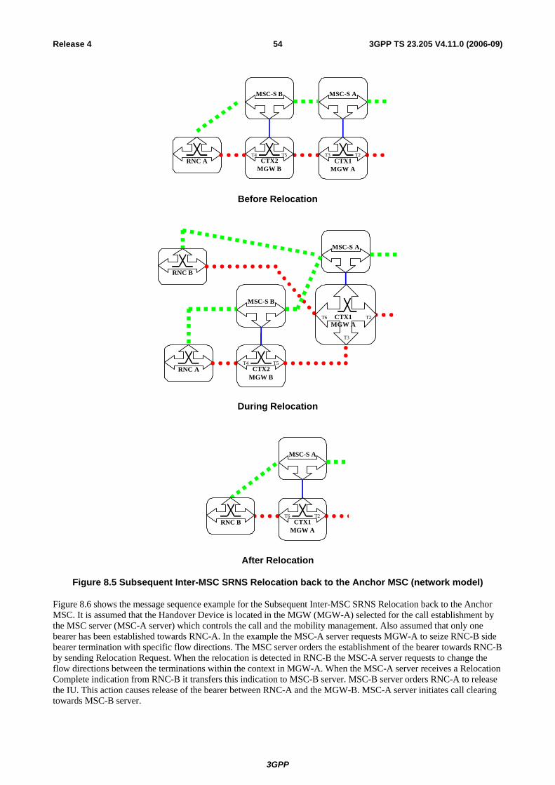
3GPP
3GPP TS 23.205 V4.11.0 (2006-09)54Release 4
MSC-S A
CTX1T3 T2
MGW ARNC A CTX2
T4 T5
MGW B
MSC-S B
Before Relocation
MSC-S A
RNC B
CTX1MGW A
T6 T2
T3
RNC A CTX2T4 T5
MGW B
MSC-S B
During Relocation
MSC-S A
CTX1T6 T2
MGW ARNC B
After Relocation
Figure 8.5 Subsequent Inter-MSC SRNS Relocation back to the Anchor MSC (network model)
Figure 8.6 shows the message sequence example for the Subsequent Inter-MSC SRNS Relocation back to the Anchor MSC. It is assumed that the Handover Device is located in the MGW (MGW-A) selected for the call establishment by the MSC server (MSC-A server) which controls the call and the mobility management. Also assumed that only one bearer has been established towards RNC-A. In the example the MSC-A server requests MGW-A to seize RNC-B side bearer termination with specific flow directions. The MSC server orders the establishment of the bearer towards RNC-B by sending Relocation Request. When the relocation is detected in RNC-B the MSC-A server requests to change the flow directions between the terminations within the context in MGW-A. When the MSC-A server receives a Relocation Complete indication from RNC-B it transfers this indication to MSC-B server. MSC-B server orders RNC-A to release the IU. This action causes release of the bearer between RNC-A and the MGW-B. MSC-A server initiates call clearing towards MSC-B server.

3GPP
3GPP TS 23.205 V4.11.0 (2006-09)55Release 4
Context(C1) Add.reply (T6)
MAP Prepare Subsequent Handover Req.
RNC B MGW A RNC AMSC-S A
Iu Relocation Required
Iu Relocation Request
Iu Relocation Request-Ack
MSC-S B MGW B
MAP Prepare Subsequent Handover Resp.
Iu Relocation Command
Relocationexecutiontriggeredin target
RNC
Context(C1) Add.request ($)
Iu Relocation Detect
Context(C1) Mod.request (T2,T6,bothway)
Context(C1) Mod.reply (T2,T6)
Context(C1) Mod.request (T2,T3,oneway)
Context(C1) Mod.reply (T2,T3)
1
2 Change Flow Direction
Change Flow Direction
Prepare bearer
Context(C1) Mod.request (T2,T6,oneway)
Context(C1) Mod.reply (T2,T6)Change Flow Direction
Context(C1) Mod.request (T3,T6,isolate)
Context(C1) Mod.reply (T3,T6)Change Flow Direction
Bearer Establishment
Figure 8.6/1 Subsequent Inter-MSC SRNS Relocation back to the Anchor MSC (message sequence chart)

3GPP
3GPP TS 23.205 V4.11.0 (2006-09)56Release 4
RNC B MGW A RNC AMSC-S A MGW B
MAP Send End Signal Resp.
Iu Release Command
Releaseof
bearer
Iu Release Complete
Iu Relocation Complete
Context(C2) SUB.request (T4)
Context(C2) SUB.reply (T4)
MSC-S B
3
Call Clearing and Bearer Release
Figure 8.6/2 Subsequent Inter-MSC SRNS Relocation back to the Anchor MSC (message sequence chart)
8.1.4 Subsequent Inter-MSC SRNS Relocation to a third MSC The relocation to a third MSC server (from MSC-B server to MSC-B' server) is the combination of the two previous inter-MSC handover cases:
- for MSC-B server a subsequent relocation from MSC-B server back to MSC-A server as described in clause 8.1.3; and
- for MSC-B' server a basic relocation from MSC-A server to MSC-B' server as described in clause 8.1.2.
MSC-A server implements the corresponding parts of each handover case; i.e. access handling in MSC-A server is not included.
8.2 UMTS to GSM
8.2.1 Intra-MSC UMTS to GSM Handover The procedures specified in 3GPP TS 23.009 [8] for 'Intra-3G_MSC Handover from UMTS to GSM' shall be followed. The following paragraphs describe the additional requirements for the bearer independent CS core network.
Relocation Required
When the MSC server receives the Relocation Required message, it requests the MGW to seize a TDM circuit, using the Reserve Circuit procedure. For non-speech calls the MSC server shall provide the MGW with the GSM Channel coding properties and the same PLMN Bearer Capability [4] as was provided at the last access bearer assignment. The MSC server uses the Change Flow Direction procedure to request the MGW to set the Handover Device to initial state. The MSC server sends the Handover Request message, containing the CIC, to BSC-B (bullet 1 in figure 8.8/1).
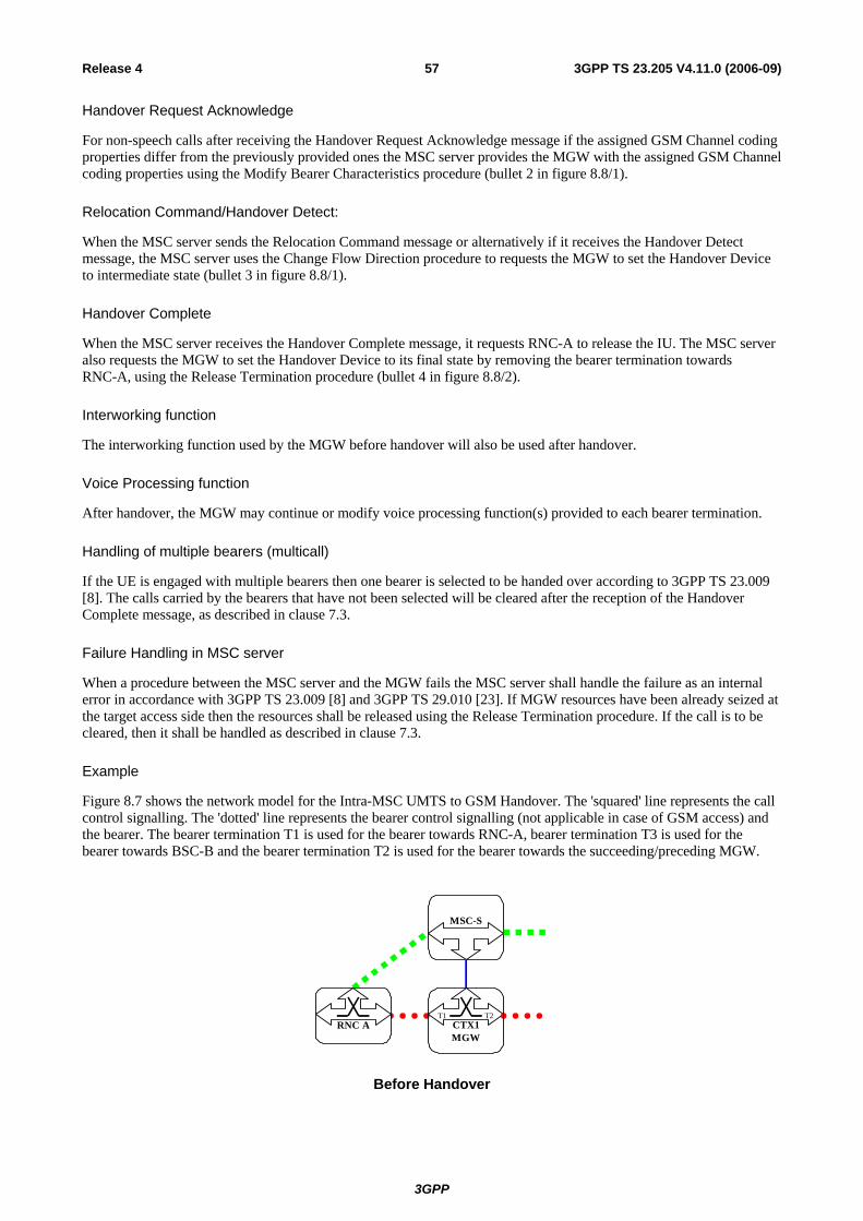
3GPP
3GPP TS 23.205 V4.11.0 (2006-09)57Release 4
Handover Request Acknowledge
For non-speech calls after receiving the Handover Request Acknowledge message if the assigned GSM Channel coding properties differ from the previously provided ones the MSC server provides the MGW with the assigned GSM Channel coding properties using the Modify Bearer Characteristics procedure (bullet 2 in figure 8.8/1).
Relocation Command/Handover Detect:
When the MSC server sends the Relocation Command message or alternatively if it receives the Handover Detect message, the MSC server uses the Change Flow Direction procedure to requests the MGW to set the Handover Device to intermediate state (bullet 3 in figure 8.8/1).
Handover Complete
When the MSC server receives the Handover Complete message, it requests RNC-A to release the IU. The MSC server also requests the MGW to set the Handover Device to its final state by removing the bearer termination towards RNC-A, using the Release Termination procedure (bullet 4 in figure 8.8/2).
Interworking function
The interworking function used by the MGW before handover will also be used after handover.
Voice Processing function
After handover, the MGW may continue or modify voice processing function(s) provided to each bearer termination.
Handling of multiple bearers (multicall)
If the UE is engaged with multiple bearers then one bearer is selected to be handed over according to 3GPP TS 23.009 [8]. The calls carried by the bearers that have not been selected will be cleared after the reception of the Handover Complete message, as described in clause 7.3.
Failure Handling in MSC server
When a procedure between the MSC server and the MGW fails the MSC server shall handle the failure as an internal error in accordance with 3GPP TS 23.009 [8] and 3GPP TS 29.010 [23]. If MGW resources have been already seized at the target access side then the resources shall be released using the Release Termination procedure. If the call is to be cleared, then it shall be handled as described in clause 7.3.
Example
Figure 8.7 shows the network model for the Intra-MSC UMTS to GSM Handover. The 'squared' line represents the call control signalling. The 'dotted' line represents the bearer control signalling (not applicable in case of GSM access) and the bearer. The bearer termination T1 is used for the bearer towards RNC-A, bearer termination T3 is used for the bearer towards BSC-B and the bearer termination T2 is used for the bearer towards the succeeding/preceding MGW.
MSC-S
CTX1T1 T2
MGWRNC A
Before Handover
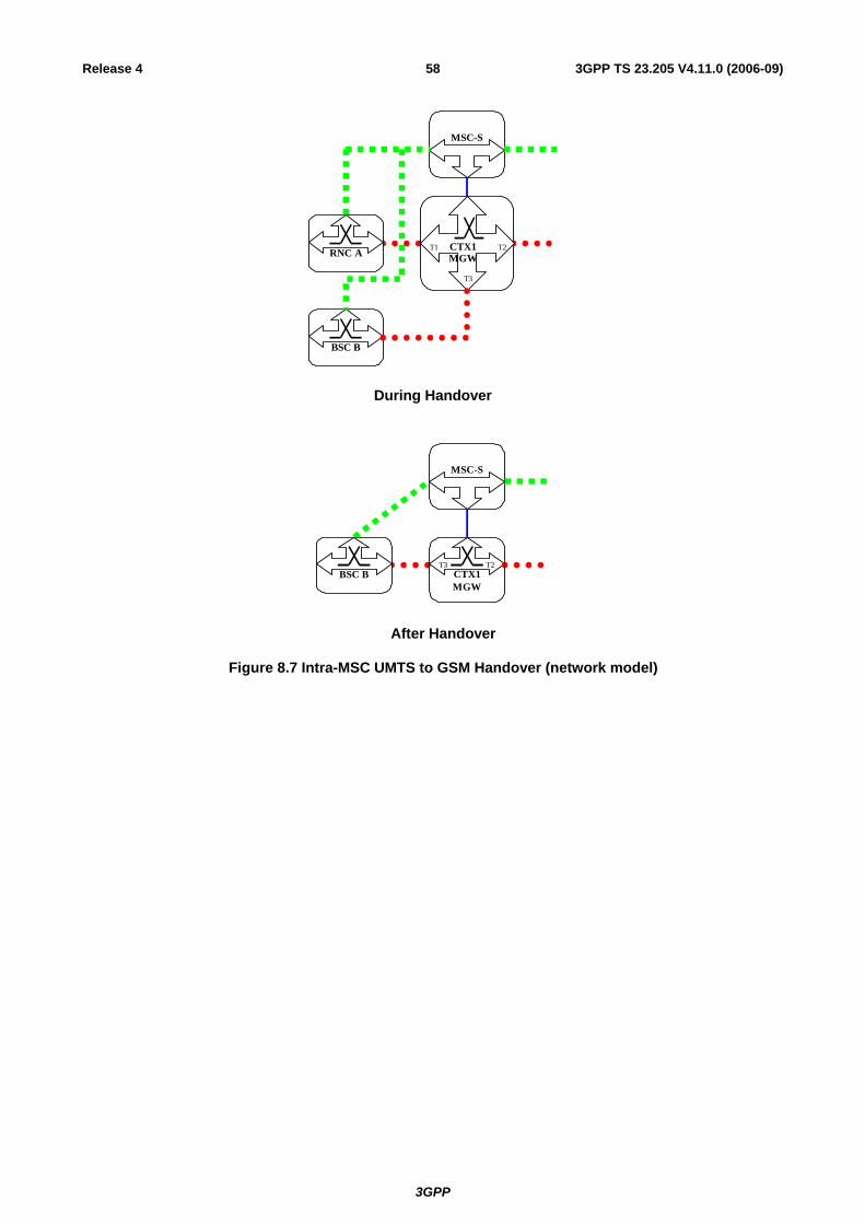
3GPP
3GPP TS 23.205 V4.11.0 (2006-09)58Release 4
MSC-S
RNC A
BSC B
CTX1MGW
T1 T2
T3
During Handover
MSC-S
CTX1T3 T2
MGWBSC B
After Handover
Figure 8.7 Intra-MSC UMTS to GSM Handover (network model)

3GPP
3GPP TS 23.205 V4.11.0 (2006-09)59Release 4
Figure 8.8 shows the message sequence example for the Intra-MSC UMTS to GSM Handover. It is assumed that the Handover Device is located in the MGW selected for the call establishment by the MSC server, which controls the call and the mobility management. It is also assumed that only one bearer has been established towards RNC-A and that MGW-A is capable of handling GSM access. In the example the MSC server requests seizure of BSC-B side bearer termination with specific flow directions. The MSC server starts handover execution by sending Handover Request towards BSC-B. When the handover is detected in BSC-B the MSC server requests to change the flow directions between the terminations within the context. When MSC server receives Handover Complete indication from BSC-B it orders RNC-A to release the IU. Finally the MSC server requests the MGW to release RNC-A side bearer termination.

3GPP
3GPP TS 23.205 V4.11.0 (2006-09)60Release 4
RNC A MGW BSC BMSC-S
Iu Relocation Required
Handoverdetected in target
BSC
A Handover Detect
Context(C1) MOD.request (T2,T3,bothway)
Context(C1) MOD.reply (T2,T3)
Context(C1) MOD.request (T2,T1,oneway)
Context(C1) MOD.reply (T2,T1)
3 Change Flow Direction
Change Flow Direction
A Handover Request-Ack
Iu Relocation Command
Context(C1) ADD.reply (T3)
Context(C1) ADD.request (T3)
A Handover Request
1
Reserve Cirquit
Context(C1) MOD.request (T2,T3,oneway)
Context(C1) MOD.reply (T2,T3)Change Flow Direction
Context(C1) MOD.request (T1,T3,isolate)
Context(C1) MOD.reply (T1,T3)Change Flow Direction
Context(C1) MOD.request (T3)
Context(C1) MOD.reply (T3)Modify Bearer Characteristics(when applicable)
2
Figure 8.8/1 Intra-MSC UMTS to GSM Handover (message sequence chart)
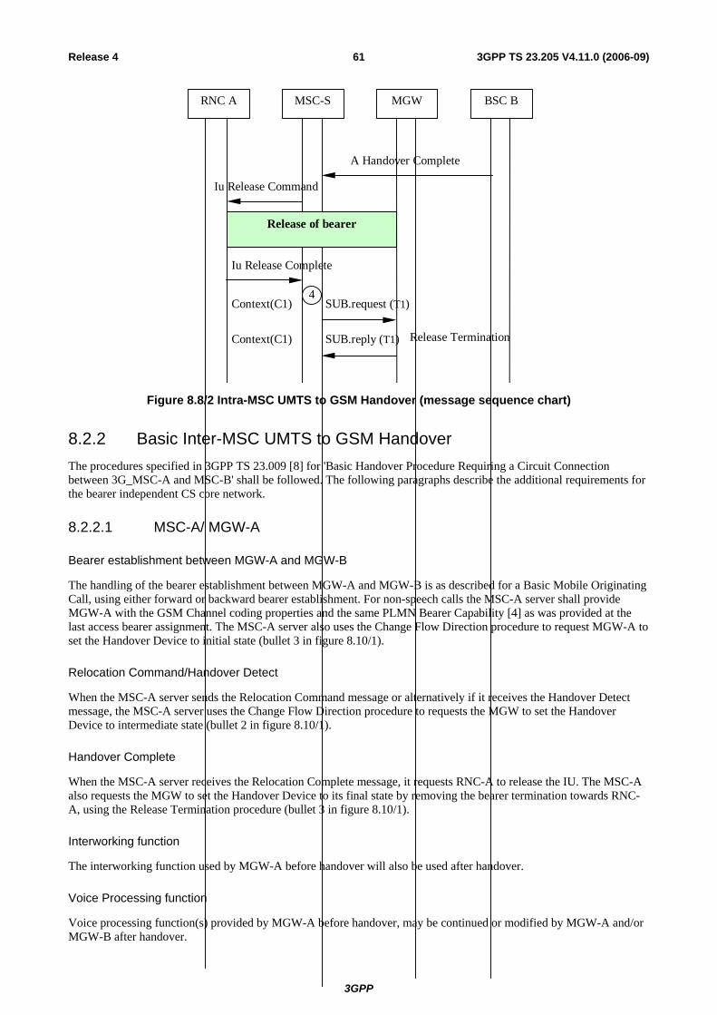
3GPP
3GPP TS 23.205 V4.11.0 (2006-09)61Release 4
RNC A MGW BSC BMSC-S
Iu Release Command
Iu Release Complete
Context(C1) SUB.request (T1)
Context(C1) SUB.reply (T1)
4
Release Termination
Release of bearer
A Handover Complete
Figure 8.8/2 Intra-MSC UMTS to GSM Handover (message sequence chart)
8.2.2 Basic Inter-MSC UMTS to GSM Handover The procedures specified in 3GPP TS 23.009 [8] for 'Basic Handover Procedure Requiring a Circuit Connection between 3G_MSC-A and MSC-B' shall be followed. The following paragraphs describe the additional requirements for the bearer independent CS core network.
8.2.2.1 MSC-A/ MGW-A
Bearer establishment between MGW-A and MGW-B
The handling of the bearer establishment between MGW-A and MGW-B is as described for a Basic Mobile Originating Call, using either forward or backward bearer establishment. For non-speech calls the MSC-A server shall provide MGW-A with the GSM Channel coding properties and the same PLMN Bearer Capability [4] as was provided at the last access bearer assignment. The MSC-A server also uses the Change Flow Direction procedure to request MGW-A to set the Handover Device to initial state (bullet 3 in figure 8.10/1).
Relocation Command/Handover Detect
When the MSC-A server sends the Relocation Command message or alternatively if it receives the Handover Detect message, the MSC-A server uses the Change Flow Direction procedure to requests the MGW to set the Handover Device to intermediate state (bullet 2 in figure 8.10/1).
Handover Complete
When the MSC-A server receives the Relocation Complete message, it requests RNC-A to release the IU. The MSC-A also requests the MGW to set the Handover Device to its final state by removing the bearer termination towards RNC-A, using the Release Termination procedure (bullet 3 in figure 8.10/1).
Interworking function
The interworking function used by MGW-A before handover will also be used after handover.
Voice Processing function
Voice processing function(s) provided by MGW-A before handover, may be continued or modified by MGW-A and/or MGW-B after handover.

3GPP
3GPP TS 23.205 V4.11.0 (2006-09)62Release 4
Handling of multiple bearers (multicall)
If the UE is engaged with multiple bearers then one bearer is selected to be handed over according to 3GPP TS 23.009 [8]. The calls carried by bearers that have not been selected will be cleared after the reception of Handover Complete message, as described in clause 7.3.
Failure Handling in MSC server
When a procedure between the MSC-A server and MGW-A fails the MSC-A server shall handle the failure as an internal error in accordance with 3GPP TS 23.009 [8] and 3GPP TS 29.010 [23]. If MGW-A resources have been already seized for the bearer towards MGW-B then the resources shall be released using the Release Termination procedure. The call towards MSC-B server shall be cleared as described in clause 7.3. If the original call is to be cleared, then it shall be handled as described in clause 7.3.
8.2.2.2 MSC-B / MGW-B
MGW selection
The MSC-B server selects an MGW when it receives Prepare Handover Request message (bullet 1 in figure 8.10/1).
Bearer establishment towards BSC-B
When the MSC-B server has selected MGW-B it requests MGW-B to seize a TDM circuit, using the Reserve Circuit procedure. The MSC-B server sends the Handover Request message to the BSC-B containing the CIC (bullet 2 in figure 8.10/1).
Bearer establishment between MGW-A and MGW-B
The handling of the bearer establishment between MGW-A and MGW-B is as described for a Basic Mobile Terminating Call, using either forward or backward bearer establishment.
Voice Processing function
Voice processing function(s) provided by MGW-A before handover, may be continued or modified by MGW-B after handover.
Failure Handling in MSC server
When a procedure between the MSC-B server and MGW-B fails the MSC-B server shall handle the failure as an internal error in accordance with 3GPP TS 23.009 [8] and 3GPP TS 29.010 [23]. If MGW-B resources have already been seized at the target access side then the resources shall be released using the Release Termination procedure. The call from MSC-A server shall be released as described at subclause 7.1.
Example
Figure 8.9 shows the network model for the Basic Inter-MSC UMTS to GSM Handover. The 'squared' line represents the call control signalling. The 'dotted' line represents the bearer control signalling (not applicable in case of GSM access) and the bearer. In MGW-A the bearer termination T1 is used for the bearer towards RNC-A, bearer termination T3 is used for the bearer towards MGW-B, and the bearer termination T2 is used for the bearer towards the succeeding/preceding MGW. In MGW-B the bearer termination T4 is used for the bearer towards BSC-B, bearer termination T5 is used for the bearer towards MGW-A.

3GPP
3GPP TS 23.205 V4.11.0 (2006-09)63Release 4
MSC-S A
CTX1T1 T2
MGW ARNC A
Before Handover
MSC-S A
RNC A
CTX1MGW A
T1 T2
T3
BSC B CTX2T4 T5
MGW B
MSC-S B
During Handover
MSC-S A
CTX1T3 T2
MGW ABSC B CTX2
T4 T5
MGW B
MSC-S B
After Handover
Figure 8.9 Basic Inter-MSC UMTS to GSM Handover (network model)

3GPP
3GPP TS 23.205 V4.11.0 (2006-09)64Release 4
Figure 8.10 shows the message sequence example for the Basic Inter-MSC UMTS to GSM Handover. It is assumed that the Handover Device is located in the MGW (MGW-A) which has been selected for the call establishment by the MSC server (MSC-A server). The MSC server controls the call and the mobility management. It is also assumed that only one bearer has been established towards RNC-A. In the example the MSC-B server requests MGW-B to seize BSC-B side bearer termination. The call is established between MSC-A server and MSC-B server, and the bearer is established between MGW-A and MGW-B. When the handover is detected in BSC-B the MSC-A server requests to change the flow directions between the terminations within the context in MGW-A. When MSC-A server receives Handover Complete indication from MSC-B server it orders RNC-A to release the IU. Finally MSC-A server requests MGW-A to remove RNC-A side bearer termination.
Context(C2) ADD.reply (T4)
Context($) ADD.request (T4)
MSC-S A MGW ARNC A
Iu Relocation Required
A Handover Request
A Handover Request-Ack
MGW B
MAP Prepare Handover Req.
MSC-S B
1
2Reserve Circuit
MAP Prepare Handover Resp.
Call and Bearer Establishment
Iu Relocation Command
Context(C1) MOD.request (T2,T3,onewayt)
Context(C1) MOD.reply (T2,T3)
Context(C1) MOD.request (T1,T3,isolate)
Context(C1) MOD.reply (T1,T3)
3 Change Flow Direction
Change Flow Direction
BSC B
Figure 8.10/1 Basic Inter-MSC UMTS to GSM Handover (message sequence chart)

3GPP
3GPP TS 23.205 V4.11.0 (2006-09)65Release 4
MGW ARNC A BSC BMSC-S A MSC-S B MGW B
4
MAP Send End Signal Req.
A Handover Complete
Answer
Context(C1) MOD.request (T2,T3,bothway)
Context(C1) MOD.reply (T2,T3)
Context(C1) MOD.request (T2,T1,oneway)
Context(C1) MOD.reply (T2,T1)
Change Flow Direction
Change Flow Direction
MAP Process Access Signalling Req.
Handover detectedin target in target
BSC
A Handover Detect
Context(C1) SUB.request (T1)
Context(C1) SUB.reply (T1) Release Termination
Release of bearer
Iu Release Command
Iu Release Complete
5
Figure 8.10/2 Basic Inter-MSC UMTS to GSM Handover (message sequence chart)
8.2.3 Subsequent Inter-MSC UMTS to GSM Handover back to the Anchor MSC
The following handling shall be applied for a call that started as UMTS call. The procedures specified in 3GPP TS 23.009 [8] for 'Subsequent UMTS to GSM handover requiring a Circuit Connection between 3G_MSC-A and 3G_MSC-B, 3G_MSC-B to MSC-A' shall be followed. The following paragraphs describe the additional requirements for the bearer independent CS core network.
3GPP
3GPP TS 23.205 V4.11.0 (2006-09)66Release 4
8.2.3.1 MSC-A
Handover Request
When the MSC-A server receives the MAP Prepare Subsequent Handover request containing a Handover Request message , it requests MGW-A to seize a TDM circuit, using the Reserve Circuit procedure. For non-speech calls the MSC-A server shall provide MGW-A with the GSM Channel coding properties and the same PLMN Bearer Capability [4] as was provided at the first access bearer assignment. The MSC-A server uses the Change Flow Direction procedure to request MGW-A to set the Handover Device to initial state. The MSC-A server sends the Handover Request message, containing the CIC, to BSC-B (bullet 1 in figure 8.12/1).
Handover Request Acknowledge
For non-speech calls after receiving the Handover Request Acknowledge message if the assigned GSM Channel coding properties differ from the previously provided ones the MSC-A server shall provide MGW-A with the assigned GSM Channel coding properties using the Modify Bearer Characteristics procedure (bullet 2 in figure 8.12/1).
Relocation Command/Handover Detect
When the MSC-A server sends the MAP Prepare Subsequent Handover response. message or alternatively if it receives the Handover Detect message, the MSC-A server uses the Change Flow Direction procedure to requests MGW-A to set the Handover Device to intermediate state (bullet 3 in figure 8.12/2).
Handover Complete
When the MSC-A server receives the Handover Complete message, it informs the MSC-B server about reception of this message (bullet 3 in figure 8.12/2). The MSC-A server then initiates call clearing towards the MSC-B server as described at 7.3.
Interworking function
The interworking function used by MGW-A before handover will also be used after handover.
Voice Processing function
Voice processing function(s) provided by MGW-A and MGW-B before handover, may be continued or modified by MGW-A after handover.
Handling of multiple bearers (multicall)
If the UE is engaged with multiple bearers the selected bearer to be handed over is received from MSC-B server in the Handover Request message according to 3GPP TS 23.009 [8]. The calls carried by the bearers that have not been selected will be cleared by MSC-A server after the reception of the Handover Complete message, as described in clause 7.3.
Failure Handling in MSC server
When a procedure between the MSC-A server and the MGW fails the MSC-A server shall handle the failure as an internal error in accordance with 3GPP TS 23.009 [8] and 3GPP TS 29.010 [23]. If MGW resources have already been seized at the target access side then the resources shall be released using the Release Termination procedure. If the call is to be cleared, then it shall be handled as described in clause 7.3.
8.2.3.2 MSC-B
Handover Complete
When the MSC-B server receives the Handover Complete message, it requests RNC-A to release the IU. The MSC-B server also requests MGW-B to remove the bearer termination towards RNC-A using the Release Termination procedure (bullet 4 in figure 8.12/2).

3GPP
3GPP TS 23.205 V4.11.0 (2006-09)67Release 4
Release of bearer towards MGW-A
When the MSC-B server receives a call clearing indication from the MSC-A server, the MSC-B server handles it as described in clause 7.2.
Handling of multiple bearers (multicall)
If the UE is engaged with multiple bearers then one bearer is selected by MSC-B server to be handed over according to 3GPP TS 23.009 [8].
Example
Figure 8.11 shows the network model for the Subsequent Inter-MSC UMTS to GSM handover back to the Anchor MSC. The 'squared' line represents the call control signalling. The 'dotted' line represents the bearer control signalling (not applicable in case of GSM access) and the bearer. In MGW-A the bearer termination T6 is used for the bearer towards BSC-B, bearer termination T3 is used for the bearer towards MGW-B, and the bearer termination T2 is used for the bearer towards the succeeding/preceding MGW. In MGW-B the bearer termination T4 is used for the bearer towards RNC-A, bearer termination T5 is used for the bearer towards MGW-A.
MSC-S A
CTX1T3 T2
MGW ARNC A CTX2
T4 T5
MGW B
MSC-S B
Before Handover
MSC-S A
BSC B
CTX1MGW A
T6 T2
T3
RNC A CTX2T4 T5
MGW B
MSC-S B
During Handover

3GPP
3GPP TS 23.205 V4.11.0 (2006-09)68Release 4
MSC-S A
CTX1T6 T2
MGW ABSC B
After Handover
Figure 8.11 Subsequent Inter-MSC UMTS to GSM Handover back to the Anchor MSC (network model)

3GPP
3GPP TS 23.205 V4.11.0 (2006-09)69Release 4
Figure 8.12 shows the message sequence example for the Subsequent Inter-MSC UMTS to GSM Handover back to the Anchor MSC. It is assumed that the Handover Device is located in the MGW (MGW-A) selected for the call establishment by the MSC server (MSC-A server) which controls the call and the mobility management. Also assumed that only one bearer has been established towards RNC-A and that MGW-A is capable to handle GSM access. In the example the MSC-A server requests MGW-A to seize BSC-B side bearer termination with specific flow directions. When the relocation is detected in BSC-B the MSC-A server requests to change the flow directions between the terminations within the context in MGW-A. When MSC-A server receives Handover Complete indication from BSC-B it transfers this indication to MSC-B server. MSC-B server orders RNC-A to release the IU. MSC-A server initiates call clearing towards MSC-B server.
Context(C1) ADD.reply (T6)
MAP Prepare Subsequent Handover Req.
BSC B MGW A RNC AMSC-SA
Iu Relocation Required
A Handover Request
A Handover Request-Ack
MSC-SB
MGW B
Context(C1) ADD.request (T6) 1
Reserve Circuit
Context(C1) MOD.request (T2,T6,oneway)
Context(C1) MOD.reply(T2 T6)
Change Flow Direction
Context(C1) MOD.request (T3,T6,isolate)
Context(C1) MOD.reply(T3 T6)
Change Flow Direction
Context(C1) MOD.request (T6)
Context(C1) MOD.reply (T6)Modify Bearer Characteristics(when applicable)
2
Figure 8.12/1 Subsequent Inter-MSC UMTS to GSM Handover back to the Anchor MSC (message sequence chart)

3GPP
3GPP TS 23.205 V4.11.0 (2006-09)70Release 4
BSC B MGW A RNC AMSC-S A MGW B
MAP Send End Signal Resp.
Iu Release Command
Releaseof
bearer
Iu Release Complete
A Handover Complete
MSC-S B
4
Handoverdetected in target
BSC
A Handover Detect
Context(C1) MOD.request (T2,T6,bothway)
Context(C1) MOD.reply (T2,T6)
Context(C1) MOD.request (T2,T3,oneway)
Context(C1) MOD.reply (T2,T3)
3
Change Flow Direction
Change Flow Direction
MAP Prepare Subsequent Handover Resp.
Iu Relocation Command
Context(C2) SUB.request (T4)
Context(C2) SUB.reply (T4)
Call Clearing and Bearer Release
Figure 8.12/2 Subsequent Inter-MSC UMTS to GSM Handover back to the Anchor MSC (message sequence chart)

3GPP
3GPP TS 23.205 V4.11.0 (2006-09)71Release 4
8.2.4 Subsequent Inter-MSC UMTS to GSM Handover to a third MSC The UMTS to GSM handover to a third MSC server (from MSC-B server to MSC-B' server) is the combination of the two previous inter-MSC handover cases:
- for MSC-B server a subsequent UMTS to GSM handover from MSC-B server back to MSC-A server as described in clause 8.2.3; and
- for MSC-B' server a basic UMTS to GSM handover from MSC-A server to MSC-B' server as described in clause 8.2.2.
MSC-A server implements the corresponding parts of each handover case; i.e. access handling in MSC-A server is not included.
8.3 GSM to UMTS
8.3.1 Intra-MSC GSM to UMTS Handover The procedures specified in 3GPP TS 23.009 [8] for 'Intra-3G_MSC GSM to UMTS Handover' shall be followed. The following paragraphs describe the additional requirements for the bearer independent CS core network.
Handover Required
When the MSC server receives the Handover Required message, it requests the MGW to provide a binding reference and a bearer address using the Prepare Bearer procedure. For speech calls, the MSC server shall provide the MGW with the speech coding information for the bearer. For non-speech calls the MSC server shall provide the MGW with the same PLMN Bearer Capability [4] as was provided at the last channel assignment. The MSC server uses the Change Flow Direction procedure to request the MGW to set the Handover Device to initial state. The MSC server sends the Relocation Request message to the RNC-B containing the bearer address and binding reference (bullet 1 in figure 8.14).
Handover Command/Relocation Detect
When the MSC server sends the Handover Command message or alternatively if it receives a Relocation Detect message, the MSC server uses the Change Flow Direction procedure to requests the MGW to set the Handover Device to intermediate state (bullet 2 in figure 8.14).
Relocation Complete
When the MSC server receives the Relocation Complete message, it releases the A-interface line towards BSC-A and requests the MGW to set the Handover Device to its final state removing the bearer termination towards BSC-A, using Release Termination procedure (bullet 3 in figure 8.14).
Interworking function
The interworking function used by the MGW before handover will also be used after handover.
Codec handling
The MGW may include a speech transcoder based upon the speech coding information provided to each bearer termination.
Voice Processing function
After handover, the MGW may continue or modify voice processing function(s) provided to each bearer termination.

3GPP
3GPP TS 23.205 V4.11.0 (2006-09)72Release 4
Failure Handling in MSC server
When a procedure between the MSC server and the MGW fails the MSC server shall handle the failure as an internal error in accordance with 3GPP TS 23.009 [8] and 3GPP TS 29.010 [23]. If MGW resources have already been seized at the target access side then the resources shall be released using the Release Termination procedure. If the call is to be cleared, then it shall be handled as described in clause 7.3.
Example
Figure 8.13 shows the network model for the Intra-3G_MSC GSM to UMTS Handover. The 'squared' line represents the call control signalling. The 'dotted' line represents the bearer control signalling and the bearer. The bearer termination T1 is used for the bearer towards the BSC-A (connected through the MSC server), the bearer termination T3 is used for the bearer towards the RNC-B and the bearer termination T2 is used for the bearer towards the succeeding/preceding MGW.
MSC-S
CTX1T1 T2
MGWBSC A
Before Handover
MSC-S
BSC A
RNC B
CTX1MGW
T1 T2
T3
During Handover
MSC-S
CTX1T3 T2
MGWRNC B
After Handover
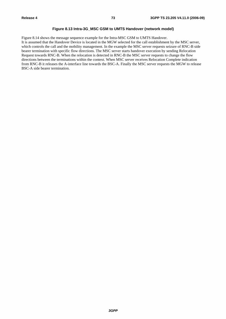
3GPP
3GPP TS 23.205 V4.11.0 (2006-09)73Release 4
Figure 8.13 Intra-3G_MSC GSM to UMTS Handover (network model)
Figure 8.14 shows the message sequence example for the Intra-MSC GSM to UMTS Handover. It is assumed that the Handover Device is located in the MGW selected for the call establishment by the MSC server, which controls the call and the mobility management. In the example the MSC server requests seizure of RNC-B side bearer termination with specific flow directions. The MSC server starts handover execution by sending Relocation Request towards RNC-B. When the relocation is detected in RNC-B the MSC server requests to change the flow directions between the terminations within the context. When MSC server receives Relocation Complete indication from RNC-B it releases the A-interface line towards the BSC-A. Finally the MSC server requests the MGW to release BSC-A side bearer termination.
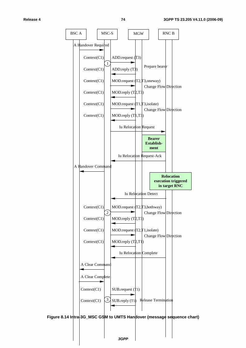
3GPP
3GPP TS 23.205 V4.11.0 (2006-09)74Release 4
Context(C1) ADD.reply (T3)
Context(C1) ADD.request (T3)
RNC BMSC-S MGWBSC A
A Handover Required
Iu Relocation Request
BearerEstablish-
ment
Iu Relocation Request-Ack
1Prepare bearer
Context(C1) MOD.request (T2,T3,oneway)
Context(C1) MOD.reply (T2,T3)Change Flow Direction
Context(C1) MOD.request (T1,T3,isolate)
Context(C1) MOD.reply (T1,T3)Change Flow Direction
Iu Relocation Complete
A Clear Command
A Clear Complete
Context(C1) SUB.request (T1)
Context(C1) SUB.reply (T1) 3 Release Termination
A Handover Command
Relocationexecution triggered
in target RNC
Iu Relocation Detect
Context(C1) MOD.request (T2,T3,bothway)
Context(C1) MOD.reply (T2,T3)
Context(C1) MOD.request (T2,T1,isolate)
Context(C1) MOD.reply (T2,T1)
2 Change Flow Direction
Change Flow Direction
Figure 8.14 Intra-3G_MSC GSM to UMTS Handover (message sequence chart)

3GPP
3GPP TS 23.205 V4.11.0 (2006-09)75Release 4
8.3.2 Basic Inter-MSC GSM to UMTS Handover The following handling shall be applied for a call that started as UMTS call. The procedures specified in 3GPP TS 23.009 [8] for 'Basic Handover Procedure Requiring a Circuit Connection between MSC-A and 3G_MSC-B' shall be followed. The following paragraphs describe the additional requirements for the bearer independent CS core network.
8.3.2.1 MSC-A
Bearer establishment between MGW-A and MGW-B
The handling of the bearer establishment between MGW-A and MGW-B is as described for a Basic Mobile Originating Call, using either forward or backward bearer establishment. For speech calls, the MSC-A server shall provide the MGW-A with the speech coding information for the bearer. For non-speech calls the MSC-A server shall provide MGW-A with the same PLMN Bearer Capabilities [4] as were provided at the last access bearer assignment. The MSC-A server also uses the Change Flow Direction procedure to request MGW-A to set the Handover Device to initial state (bullet 3 in figure 8.16/1).
Handover Command/Handover Detect
When the MSC-A server sends the Handover Command message or alternatively if it receives the Handover Detect message, the MSC-A server uses the Change Flow Direction procedure to requests MGW-A to set the Handover Device to intermediate state (bullet 4 in figure 8.16/2).
Handover Complete
When the MSC-A server receives the Handover Complete message, it releases the A-interface line towards BSC-A and requests MGW-A to set the Handover Device to its final state by removing the bearer termination towards BSC-A, using Release Termination procedure (bullet 5 in figure 8.16/2).
Interworking function
The interworking function used by MGW-A before handover will also be used after handover.
Codec handling
The MGW may include a speech transcoder based upon the speech coding information provided to each bearer termination.
Voice Processing function
Voice processing function(s) provided by MGW-A before handover, may be modified or disabled by MGW-A after handover.
Failure Handling in MSC server
When a procedure between the MSC-A server and MGW-A fails the MSC-A server shall handle the failure as an internal error in accordance with 3GPP TS 23.009 [8] and 3GPP TS 29.010 [23]. If the call establishment towards MSC-B has already started then the call towards MSC-B server shall be cleared as described in clause 7.3. If the original call is to be cleared, then it shall be handled as described in clause 7.3.
8.3.2.2 MSC-B
MGW selection
The MSC-B server selects an MGW when it receives Prepare Handover Request message (bullet 1 in figure 8.16).
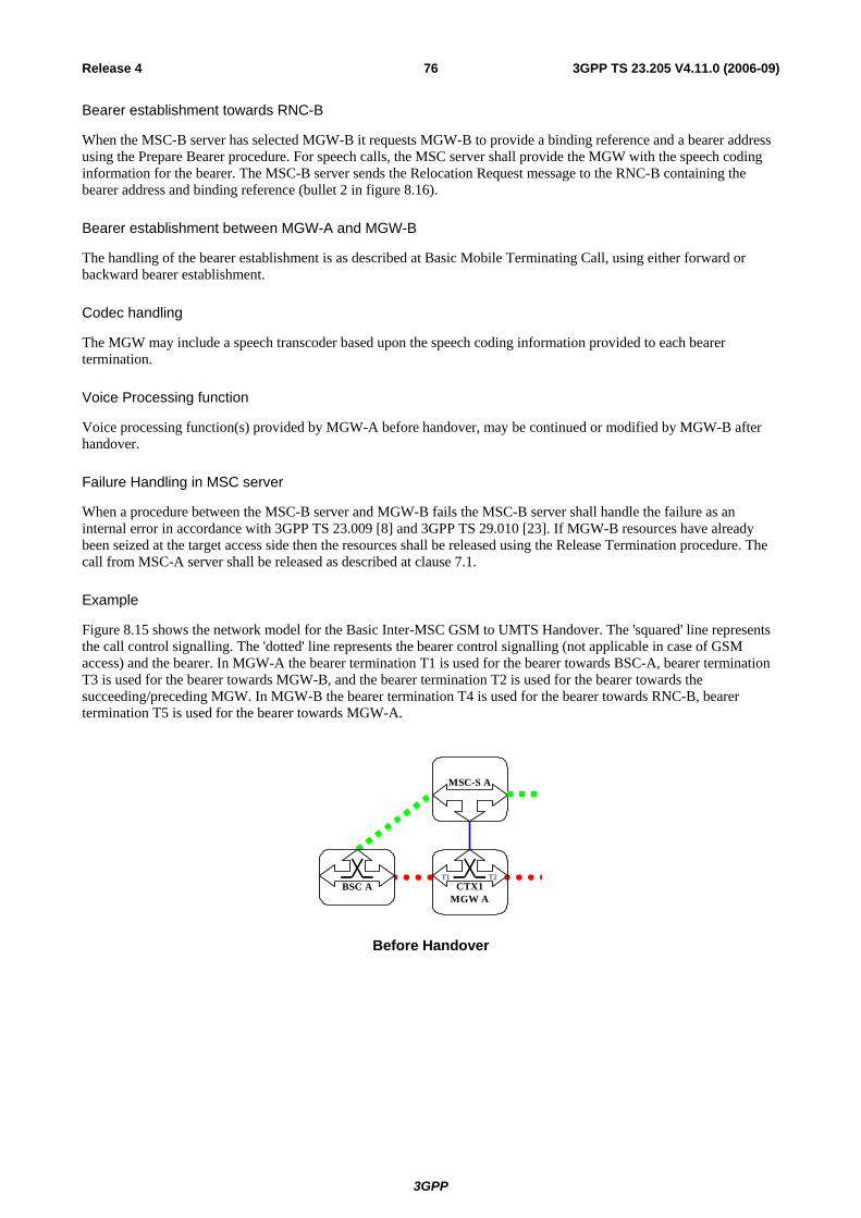
3GPP
3GPP TS 23.205 V4.11.0 (2006-09)76Release 4
Bearer establishment towards RNC-B
When the MSC-B server has selected MGW-B it requests MGW-B to provide a binding reference and a bearer address using the Prepare Bearer procedure. For speech calls, the MSC server shall provide the MGW with the speech coding information for the bearer. The MSC-B server sends the Relocation Request message to the RNC-B containing the bearer address and binding reference (bullet 2 in figure 8.16).
Bearer establishment between MGW-A and MGW-B
The handling of the bearer establishment is as described at Basic Mobile Terminating Call, using either forward or backward bearer establishment.
Codec handling
The MGW may include a speech transcoder based upon the speech coding information provided to each bearer termination.
Voice Processing function
Voice processing function(s) provided by MGW-A before handover, may be continued or modified by MGW-B after handover.
Failure Handling in MSC server
When a procedure between the MSC-B server and MGW-B fails the MSC-B server shall handle the failure as an internal error in accordance with 3GPP TS 23.009 [8] and 3GPP TS 29.010 [23]. If MGW-B resources have already been seized at the target access side then the resources shall be released using the Release Termination procedure. The call from MSC-A server shall be released as described at clause 7.1.
Example
Figure 8.15 shows the network model for the Basic Inter-MSC GSM to UMTS Handover. The 'squared' line represents the call control signalling. The 'dotted' line represents the bearer control signalling (not applicable in case of GSM access) and the bearer. In MGW-A the bearer termination T1 is used for the bearer towards BSC-A, bearer termination T3 is used for the bearer towards MGW-B, and the bearer termination T2 is used for the bearer towards the succeeding/preceding MGW. In MGW-B the bearer termination T4 is used for the bearer towards RNC-B, bearer termination T5 is used for the bearer towards MGW-A.
MSC-S A
CTX1T1 T2
MGW ABSC A
Before Handover
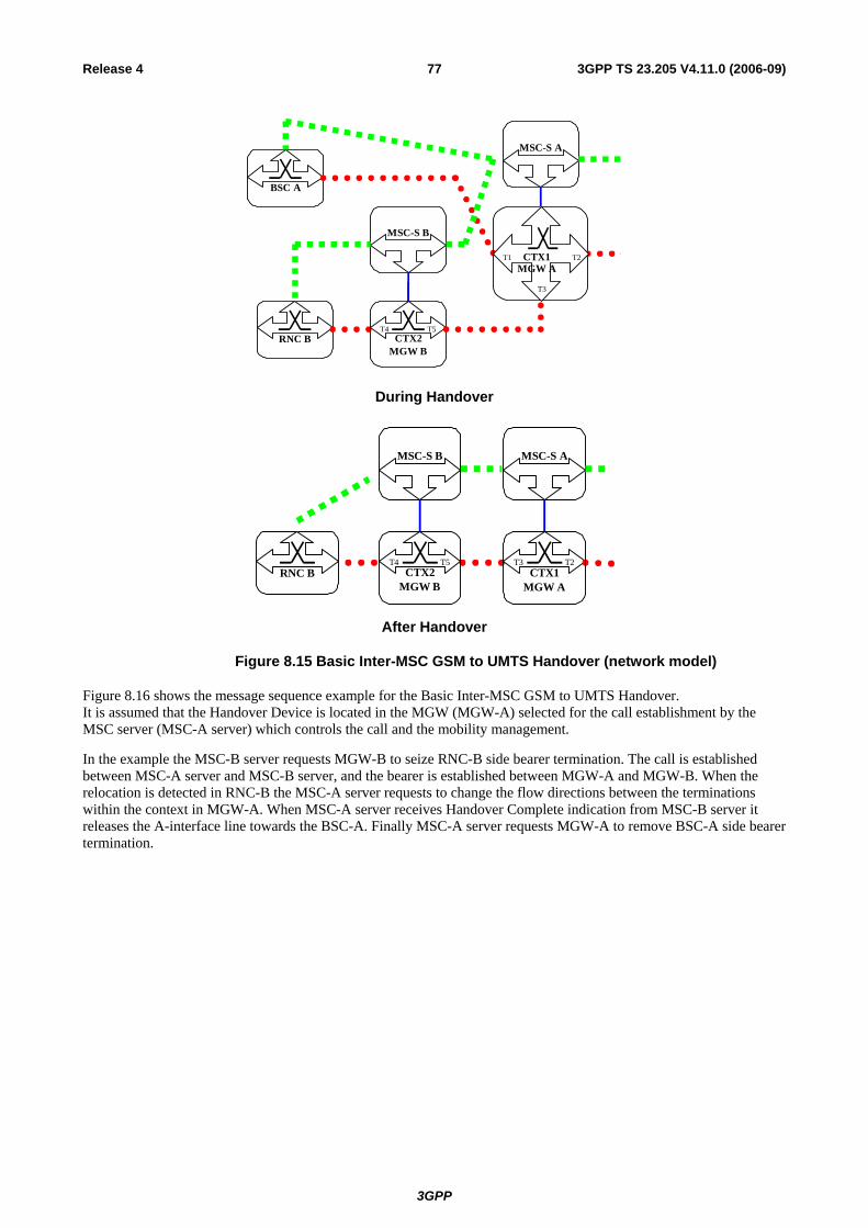
3GPP
3GPP TS 23.205 V4.11.0 (2006-09)77Release 4
MSC-S A
BSC A
CTX1MGW A
T1 T2
T3
RNC B CTX2T4 T5
MGW B
MSC-S B
During Handover
MSC-S A
CTX1T3 T2
MGW ARNC B CTX2
T4 T5
MGW B
MSC-S B
After Handover
Figure 8.15 Basic Inter-MSC GSM to UMTS Handover (network model)
Figure 8.16 shows the message sequence example for the Basic Inter-MSC GSM to UMTS Handover. It is assumed that the Handover Device is located in the MGW (MGW-A) selected for the call establishment by the MSC server (MSC-A server) which controls the call and the mobility management.
In the example the MSC-B server requests MGW-B to seize RNC-B side bearer termination. The call is established between MSC-A server and MSC-B server, and the bearer is established between MGW-A and MGW-B. When the relocation is detected in RNC-B the MSC-A server requests to change the flow directions between the terminations within the context in MGW-A. When MSC-A server receives Handover Complete indication from MSC-B server it releases the A-interface line towards the BSC-A. Finally MSC-A server requests MGW-A to remove BSC-A side bearer termination.
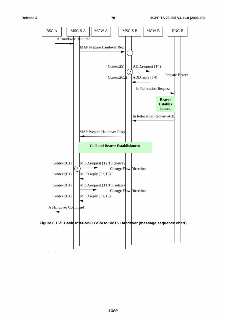
3GPP
3GPP TS 23.205 V4.11.0 (2006-09)78Release 4
Context(C2) ADD.reply (T4)
Context($) ADD.request (T4)
RNC BMSC-S A MGW ABSC A
A Handover Required
Iu Relocation Request
Iu Relocation Request-Ack
MGW B
MAP Prepare Handover Req.
BearerEstablishment
MSC-S B
1
2Prepare Bearer
MAP Prepare Handover Resp.
Call and Bearer Establishment
A Handover Command
Context(C1) MOD.request (T2,T3,oneway)
Context(C1) MOD.reply (T2,T3)
Context(C1) MOD.request (T1,T3,isolate)
Context(C1) MOD.reply (T1,T3)
3 Change Flow Direction
Change Flow Direction
Figure 8.16/1 Basic Inter-MSC GSM to UMTS Handover (message sequence chart)
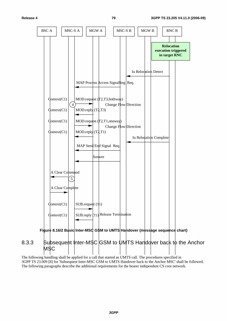
3GPP
3GPP TS 23.205 V4.11.0 (2006-09)79Release 4
MGW ABSC A RNC BMSC-S A MSC-S B MGW B
MAP Send End Signal Req.
Iu Relocation Complete
Answer
Context(C1) MOD.request (T2,T3,bothway)
Context(C1) MOD.reply (T2,T3)
Context(C1) MOD.request (T2,T1,oneway)
Context(C1) MOD.reply (T2,T1)
4 Change Flow Direction
Change Flow Direction
MAP Process Access Signalling Req.
Relocationexecution triggered
in target RNC
Iu Relocation Detect
Context(C1) SUB.request (T1)
Context(C1) SUB.reply (T1) Release Termination
A Clear Command
A Clear Complete
5
Figure 8.16/2 Basic Inter-MSC GSM to UMTS Handover (message sequence chart)
8.3.3 Subsequent Inter-MSC GSM to UMTS Handover back to the Anchor MSC
The following handling shall be applied for a call that started as UMTS call. The procedures specified in 3GPP TS 23.009 [8] for 'Subsequent Inter-MSC GSM to UMTS Handover back to the Anchor MSC' shall be followed. The following paragraphs describe the additional requirements for the bearer independent CS core network.

3GPP
3GPP TS 23.205 V4.11.0 (2006-09)80Release 4
8.3.3.1 MSC-A
Handover Request
When the MSC-A server receives a MAP Prepare Subsequent Handover request containing a Handover Request message, it requests the MGW-A to provide a binding reference and a bearer address using the Prepare Bearer procedure. For speech calls, the MSC-A server shall provide the MGW-A with the speech coding information for the bearer. For non-speech calls the MSC-A server shall provide MGW-A with the same PLMN Bearer Capability [4] as was provided at the last channel assignment. The MSC-A server uses the Change Flow Direction Procedure to request the MGW-A to set the Handover Device to initial state. The MSC-A server sends the Relocation Request message to the RNC-B containing the bearer address and binding reference (bullet 1 in figure 8.18/1).
Handover Command/Relocation Detect
When the MSC-A server sends the MAP Prepare Subsequent Handover response message or alternatively if it receives a Relocation Detect message, the MSC-A server uses the Change Flow Direction procedure to requests the MGW-A to set the Handover Device to intermediate state (bullet 2 in figure 8.18/2).
Relocation Complete
When the MSC-A server receives a Relocation Complete message, it informs the MSC-B server about reception of this message. MSC-A server then initiates call clearing towards the MSC-B server as described in clause 7.3.
Interworking function
The interworking function used by MGW-A before handover will also be used after handover.
Codec handling
The MGW may include a speech transcoder based upon the speech coding information provided to each bearer termination.
Voice Processing function
Voice processing function(s) provided by MGW-A and MGW-B before handover, may be continued or modified by MGW-A after handover.
Failure Handling in MSC server
When a procedure between the MSC-A server and the MGW fails the MSC-A server shall handle the failure as an internal error in accordance with 3GPP TS 23.009 [8] and 3GPP TS 29.010 [23]. If MGW resources have been already seized at the target access side then the resources shall be released using the Release Termination procedure. If the call is to be cleared, then it shall be handled as described in clause 7.3.
8.3.3.2 MSC-B / MGW-B
Handover Complete
When the MSC-B server receives the Handover Complete message, it releases the A-interface line towards the BSC-A and requests the MGW-B to remove the bearer termination towards the BSC-A using the Release Termination procedure (bullet 3 in figure 8.18/2).
Release of bearer towards MGW-A
When the MSC-B server receives a call clearing indication from the MSC-A server, the MSC-B server handles it as described in subclause 7.2.

3GPP
3GPP TS 23.205 V4.11.0 (2006-09)81Release 4
Example
Figure 8.17 shows the network model for Subsequent Inter-MSC GSM to UMTS Handover back to the Anchor MSC. The 'squared' line represents the call control signalling. The 'dotted' line represents the bearer control signalling (not applicable in case of GSM access) and the bearer. In the MGW the bearer termination T1 is used for the bearer towards RNC-B, the bearer termination T3 is used for the bearer towards MSC-A server, and the bearer termination T2 is used for the bearer towards the succeeding/preceding MGW. In MGW-B the bearer termination T4 is used for the bearer towards BSC-A, bearer termination T5 is used for the bearer towards MGW-A.
MSC-S A
CTX1T3 T2
MGW ABSC A CTX2
T4 T5
MGW B
MSC-S B
Before Handover
MSC-S A
RNC B
CTX1MGW A
T6 T2
T3
BSC A CTX2T4 T5
MGW B
MSC-S B
During Handover
MSC-S A
CTX1T1 T2
MGW ARNC B
After Handover
Figure 8.17 Subsequent Inter-MSC GSM to UMTS Handover back to the Anchor MSC (network model)
Figure 8.18 shows the message sequence example for the Subsequent Inter-MSC GSM to UMTS Handover back to the Anchor MSC. It is assumed that the Handover Device is located in the MGW (MGW-A) selected for the call establishment by the MSC server (MSC-A server) which controls the call and the mobility management.
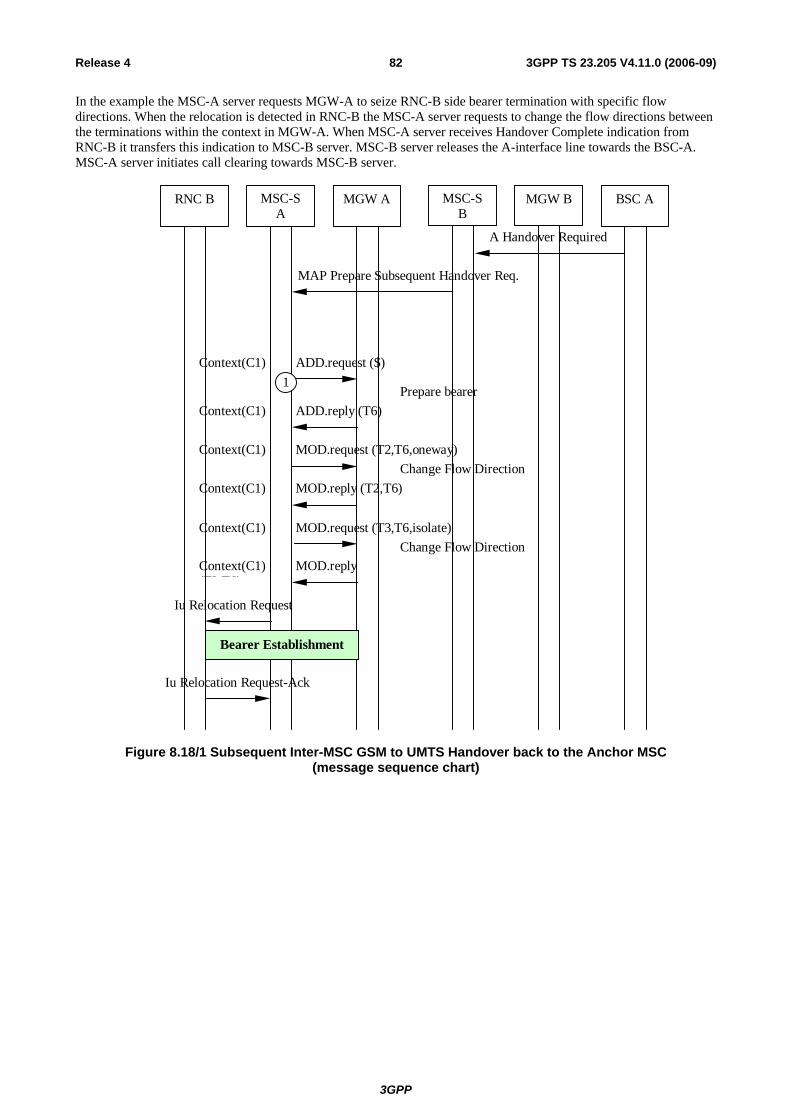
3GPP
3GPP TS 23.205 V4.11.0 (2006-09)82Release 4
In the example the MSC-A server requests MGW-A to seize RNC-B side bearer termination with specific flow directions. When the relocation is detected in RNC-B the MSC-A server requests to change the flow directions between the terminations within the context in MGW-A. When MSC-A server receives Handover Complete indication from RNC-B it transfers this indication to MSC-B server. MSC-B server releases the A-interface line towards the BSC-A. MSC-A server initiates call clearing towards MSC-B server.
Context(C1) ADD.reply (T6)
MAP Prepare Subsequent Handover Req.
RNC B MGW A BSC AMSC-SA
A Handover Required
Iu Relocation Request
Iu Relocation Request-Ack
MSC-SB
MGW B
Context(C1) ADD.request ($) 1
Prepare bearer
Context(C1) MOD.request (T2,T6,oneway)
Context(C1) MOD.reply (T2,T6)Change Flow Direction
Context(C1) MOD.request (T3,T6,isolate)
Context(C1) MOD.reply(T3 T6)
Change Flow Direction
Bearer Establishment
Figure 8.18/1 Subsequent Inter-MSC GSM to UMTS Handover back to the Anchor MSC (message sequence chart)

3GPP
3GPP TS 23.205 V4.11.0 (2006-09)83Release 4
RNC B MGW A BSC AMSC-S A MGW B
MAP Send End Signal Resp.
A Clear Command
A Clear Complete
Iu Relocation Complete
MSC-S B
3
Relocationexecution triggered
in target RNC
Iu Relocation Detect
Context(C1) MOD.request (T2,T6,bothway)
Context(C1) MOD.reply (T2,T6)
Context(C1) MOD.request (T2,T3,oneway)
Context(C1) MOD.reply (T2,T3)
2
Change Flow Direction
Change Flow Direction
MAP Prepare Subsequent Handover Resp.
A Handover Command
Context(C2) SUB.request (T4)
Context(C2) SUB.reply (T4)
Call Clearing and Bearer Release
Figure 8.18/2 Subsequent Inter-MSC GSM to UMTS Handover back to the Anchor MSC (message sequence chart)
8.3.4 Subsequent Inter-MSC GSM to UMTS Handover to a third MSC The GSM to UMTS handover to a third MSC server (from MSC-B server to MSC-B' server) is the combination of the two previous inter-MSC handover cases:
- for MSC-B server a subsequent GSM to UMTS handover from MSC-B server back to MSC-A server as described in clause 8.3.3; and

3GPP
3GPP TS 23.205 V4.11.0 (2006-09)84Release 4
- for MSC-B' server a basic GSM to UMTS handover from MSC-A server to MSC-B' server as described in clause 8.3.2.
MSC-A server implements the corresponding parts of each handover case; i.e. access handling in MSC-A server is not included.
8.4 GSM to GSM
8.4.1 Intra-MSC GSM to GSM Handover The procedures specified in 3GPP TS 23.009 [8] for 'Intra-MSC Handover' shall be followed. The following paragraphs describe the additional requirements for the bearer independent CS core network.
Handover Required
When the MSC server receives a Handover Required message, it requests the MGW to seize a TDM circuit, using the Reserve Circuit procedure. For non-speech calls the MSC server shall provide the MGW with the GSM Channel coding properties and the same PLMN Bearer Capability [4] as was provided at the last access bearer assignment. The MSC server uses the Change Flow Direction procedure to request the MGW to set the Handover Device to initial state. The MSC server sends the Handover Request message to the BSC-B containing the CIC (bullet 1 in figure 8.20/1).
Handover Request Acknowledge
For non-speech calls after receiving Handover Request Acknowledge message if the assigned GSM Channel coding properties differ from the previously provided ones the MSC server provides the MGW-A with the assigned GSM Channel coding properties using the Modify Bearer Characteristics procedure (bullet 2 in figure 8.20/1).
Handover Command/Handover Detect
When the MSC server sends the Handover Command message or alternatively if it receives the Handover Detect message, the MSC server uses the Change Flow Direction procedure to requests the MGW to set the Handover Device to intermediate state (bullet 3 in figure 8.20/1).
Handover Complete
When the MSC server receives the Handover Complete message, it releases the A-interface line towards BSC-A. The MSC server also requests the MGW to set the Handover Device to its final state by removing the bearer termination towards the BSC-A, using the Release Termination procedure (bullet 4 in figure 8.20/2).
Interworking function
The interworking function used by the MGW before handover will also be used after handover.
Voice Processing function
After handover, the MGW may continue or modify voice processing function(s) provided to each bearer termination.
Failure Handling in MSC server
When a procedure between the MSC server and the MGW fails the MSC server shall handle the failure as an internal error in accordance with 3GPP TS 23.009 [8] and 3GPP TS 29.010 [23]. If MGW resources have already been seized at the target access side then the resources shall be released using the Release Termination procedure. If the call is to be cleared, then it shall be handled as described in clause 7.3.

3GPP
3GPP TS 23.205 V4.11.0 (2006-09)85Release 4
Example
Figure 8.19 shows the network model for the Intra-MSC GSM to GSM Handover. The 'squared' line represents the call control signalling. The 'dotted' line represents the bearer. The bearer termination T1 is used for the bearer towards BSC-A, bearer termination T3 is used for the bearer towards BSC-B and the bearer termination T2 is used for the bearer towards the succeeding/preceding MGW.
MSC-S
CTX1T1 T2
MGWBSC A
Before Handover
MSC-S
BSC A
BSC B
CTX1MGW
T1 T2
T3
During Handover
MSC-S
CTX1T3 T2
MGWBSC B
After Handover
Figure 8.19 Intra-MSC GSM to GSM Handover (network model)
Figure 8.20 shows the message sequence example for the Intra-MSC GSM to GSM Handover. It is assumed that the Handover Device is located in the MGW selected for the call establishment by the MSC server, which controls the call and the mobility management.

3GPP
3GPP TS 23.205 V4.11.0 (2006-09)86Release 4
In the example the MSC server requests seizure of BSC-B side bearer termination with specific flow directions. The MSC server starts handover execution by sending Handover Request towards BSC-B. When the handover is detected in BSC-B the MSC server requests to change the flow directions between the terminations within the context. When MSC server receives Handover Complete indication from BSC-B it releases the A-interface line towards the BSC-A. Finally the MSC server requests the MGW to release BSC-A side bearer termination.
BSC A
A Handover Required
Context(C1) ADD.reply (T3)
Context(C1) ADD.request (T3)
A Handover Request
A Handover Request-Ack
1Reserve Circuit
Context(C1) MOD.request (T2,T3,oneway)
Context(C1) MOD.reply (T2,T3)Change Flow Direction
Context(C1) MOD.request (T1,T3, isolate)
Context(C1) MOD.reply (T1,T3)Change Flow Direction
A Handover Complete
A Handover Command
Handover detectedin target BSC
A Handover Detect
Context(C1) MOD.request (T2,T3,bothway)
Context(C1) MOD.reply (T2,T3)
Context(C1) MOD.request (T2,T1,oneway)
Context(C1) MOD.reply (T2,T1)
3 Change Flow Direction
Change Flow Direction
MSC-S MGW BSC B
Context(C1) MOD.request (T3)
Context(C1) MOD.reply (T3)Modify Bearer Characteristics(when applicable)
2
Figure 8.20/1 Intra-MSC GSM to GSM Handover (message sequence chart)

3GPP
3GPP TS 23.205 V4.11.0 (2006-09)87Release 4
BSC A
A Clear Command
A Clear Complete
Context(C1) SUB.request (T1)
Context(C1) SUB.reply (T1)
4
Release Termination
MSC-S MGW BSC B
Figure 8.20/2 Intra-MSC GSM to GSM Handover (message sequence chart)
8.4.2 Basic Inter-MSC GSM to GSM Handover The procedures specified in 3GPP TS 23.009 [8] for 'Basic Handover Procedure Requiring a Circuit Connection between MSC-A and MSC-B' shall be followed. The following paragraphs describe the additional requirements for the bearer independent CS core network.
8.4.2.1 MSC-A / MGW-A
Bearer establishment between MGW-A and MGW-B
The handling of the bearer establishment between MGW-A and MGW-B is as described for a Basic Mobile Originating Call, using either forward or backward bearer establishment. For non-speech calls the MSC-A server shall provide MGW-A with the GSM Channel coding properties and the same PLMN Bearer Capability [4] as was provided at the last access bearer assignment. The MSC-A server also uses the Change Flow Direction procedure to request MGW-A to set the Handover Device to initial state (bullet 3 in figure 8.22/2).
Handover Command/Handover Detect
When the MSC-A server sends the Handover Command message or alternatively if it receives the Handover Detect message, the MSC-A server uses the Change Flow Direction procedure to requests MGW-A to set the Handover Device to intermediate state (bullet 4 in figure 8.22/2).
Handover Complete
When the MSC-A server receives the Handover Complete message, it releases the A-interface line towards the BSC-A. The MSC-A server also requests MGW-A to set the Handover Device to its final state by removing the bearer termination towards the BSC-A, using the Release Termination procedure (bullet 5 in figure 8.22/2).
Interworking function
The interworking function used by MGW-A before handover will also be used after handover.
Voice Processing function
Voice processing function(s) provided by MGW-A before handover, may be modified or disabled by MGW-A after handover.

3GPP
3GPP TS 23.205 V4.11.0 (2006-09)88Release 4
Failure Handling in MSC server
When a procedure between the MSC-A server and MGW-A fails the MSC-A server shall handle the failure as an internal error in accordance with 3GPP TS 23.009 [8] and 3GPP TS 29.010 [23]. If call establishment towards the MSC-B server has already started then the call towards MSC-B server shall be cleared as described in clause 7.3. If the original call is to be cleared, then it shall be handled as described in clause 7.3.
8.4.2.2 MSC-B / MGW-B
MGW selection
The MSC-B server selects an MGW when it receives Prepare Handover Request message (bullet 1 in figure 8.22/1).
Bearer establishment towards BSC-B
When the MSC-B server has selected MGW-B it requests MGW-B to seize a TDM circuit, using the Reserve Circuit procedure. The MSC-B server sends the Handover Request message to the BSC-B containing the CIC (bullet 2 in figure 8.22/1).
Bearer establishment between MGW-A and MGW-B
The handling of the bearer establishment between MGW-A and MGW-B is as described for a Basic Mobile Terminating Call, using either forward or backward bearer establishment.
Voice Processing function
Voice processing function(s) provided by MGW-A before handover, may be continued or modified by MGW-B after handover.
Failure Handling in MSC server
When a procedure between the MSC-B server and MGW-B fails the MSC-B server shall handle the failure as an internal error in accordance with 3GPP TS 23.009 [8] and 3GPP TS 29.010 [23]. If MGW-B resources have already been seized at the target access side then the resources shall be released using the Release Termination procedure. The call from MSC-A server shall be released as described at clause 7.1.
Example
Figure 8.21 shows the network model for the Basic Inter-MSC GSM to GSM. The 'squared' line represents the call control signalling. The 'dotted' line represents the bearer. In MGW-A the bearer termination T1 is used for the bearer towards BSC-A, bearer termination T3 is used for the bearer towards MGW-B, and the bearer termination T2 is used for the bearer towards the succeeding/preceding MGW. In MGW-B the bearer termination T4 is used for the bearer towards BSC-B, bearer termination T5 is used for the bearer towards MGW-A.
MSC-S A
CTX1T1 T2
MGW ABSC A
Before Handover

3GPP
3GPP TS 23.205 V4.11.0 (2006-09)89Release 4
MSC-S A
BSC A
CTX1MGW A
T1 T2
T3
BSC B CTX2T4 T5
MGW B
MSC-S B
During Handover
MSC-S A
CTX1T3 T2
MGW ABSC B CTX2
T4 T5
MGW B
MSC-S B
After Handover
Figure 8.21 Basic Inter-MSC GSM to GSM Handover (network model)
Figure 8.22 shows the message sequence example for the Basic Inter-MSC GSM to GSM Handover.
It is assumed that the Handover Device is located in the MGW (MGW-A) selected for the call establishment by the MSC server (MSC-A server) which controls the call and the mobility management.
In the example the MSC-B server requests MGW-B to seize BSC-B side bearer termination. The call is established between MSC-A server and MSC-B server, and the bearer is established between MGW-A and MGW-B. When the handover is detected in BSC-B the MSC-A server requests to change the flow directions between the terminations within the context in MGW-A. When MSC-A server receives Relocation Complete indication from MSC-B server it releases the A-interface line towards the BSC-A. Finally MSC-A server requests MGW-A to remove BSC-A side bearer termination.

3GPP
3GPP TS 23.205 V4.11.0 (2006-09)90Release 4
Context(C2) ADD.reply (T4)
Context($) ADD.request (T4)
BSC BMSC-S A MGW ABSC A
A Handover Required
A Handover Request
A Handover Request-Ack
MGW B
MAP Prepare Handover Req.
MSC-S B
1
2 Reserve Circuit
MAP Prepare Handover Resp.
Call and Bearer Establishment
Figure 8.22/1 Basic Inter-MSC GSM to GSM Handover (message sequence chart)

3GPP
3GPP TS 23.205 V4.11.0 (2006-09)91Release 4
MGW ABSC A BSC BMSC-S A MSC-S B MGW B
MAP Send End Signal Req.
A Handover Complete
Answer
Context(C1) MOD.request (T2,T3,bothway)
Context(C1) MOD.reply (T2,T3)
Context(C1) MOD.request (T2,T1,oneway)
Context(C1) MOD.reply (T2,T1)
4 Change Flow Direction
Change Flow Direction
MAP Process Access Signalling Req.
Handoverdetected intarget BSC
A Handover Detect
A Handover Command
Context(C1) MOD.request (T2,T3,oneway)
Context(C1) MOD.reply (T2,T3)
Context(C1) MOD.request (T1,T3,isolate)
Context(C1) MOD.reply (T1,T3)
3 Change Flow Direction
Change Flow Direction
A Clear Command
A Clear Complete
Context(C1) SUB.request (T1)
Context(C1) SUB.reply (T1)
5
Release Termination
Figure 8.22/2 Basic Inter-MSC GSM to GSM Handover (message sequence chart)

3GPP
3GPP TS 23.205 V4.11.0 (2006-09)92Release 4
8.4.3 Subsequent Inter-MSC GSM to GSM Handover back to the Anchor MSC
The procedures specified in 3GPP TS 23.009 [8] for 'Subsequent Handover from MSC-B to MSC-A requiring a Circuit Connection between 3G_MSC-A and 3G_MSC-B' shall be followed. The following paragraphs describe the additional requirements for the bearer independent CS core network.
8.4.3.1 MSC-A / MGW-A
Handover Request
When the MSC-A server receives a MAP Prepare Subsequent Handover request containing a Handover Request message, it requests MGW-A to seize a TDM circuit, using the Reserve Circuit procedure. For non-speech calls the MSC-A server shall provide MGW-A with the GSM Channel coding properties and the same PLMN Bearer Capability [4] as was provided at the first access bearer assignment The MSC-A server uses the Change Flow Direction Procedure to request MGW-A to set the Handover Device to initial state. The MSC-A server sends the Handover Request message to the BSC-B containing the CIC (bullet 1 in figure 8.24/1).
Handover Request Acknowledge
For non-speech calls after receiving Handover Request Acknowledge message if the assigned GSM Channel coding properties differ from the previously provided ones the MSC-A server provides the MGW-A with the assigned GSM Channel coding properties using the Modify Bearer Characteristics procedure (bullet 2 in figure 8.24/2).
Handover Command/Handover Detect
When the MSC-A server sends the MAP Prepare Subsequent Handover response message or alternatively if it receives the Handover Detect message, the MSC-A server uses the Change Flow Direction procedure to request MGW-A to set the Handover Device to intermediate state (bullet 3 in figure 8.24/2).
Handover Complete
When the MSC-A server receives the Handover Complete message, it informs the MSC-B server about reception of this message. The MSC-A server then initiates call clearing towards the MSC-B server as described in clause 7.3.
Interworking function
The interworking function used by MGW-A before handover will also be used after handover.
Voice Processing function
Voice processing function(s) provided by MGW-A and MGW-B before handover, may be continued or modified by MGW-A after handover.
Failure Handling in MSC server
When a procedure between the MSC-A server and MGW-A fails the MSC-A server shall handle the failure as an internal error in accordance with 3GPP TS 23.009 [8] and 3GPP TS 29.010 [23]. If MGW-A resources have already been seized at the target access side then the resources shall be released using the Release Termination procedure. If the call is to be cleared, then it shall be handled as described in clause 7.3.
8.4.3.2 MSC-B / MGW-B
Handover Complete
When the MSC-B server receives the Handover Complete message, it releases the A-interface line towards the BSC-A and requests the MGW-B to remove the bearer termination towards the BSC-A using the Release Termination procedure (bullet 4 in figure 8.24/2).
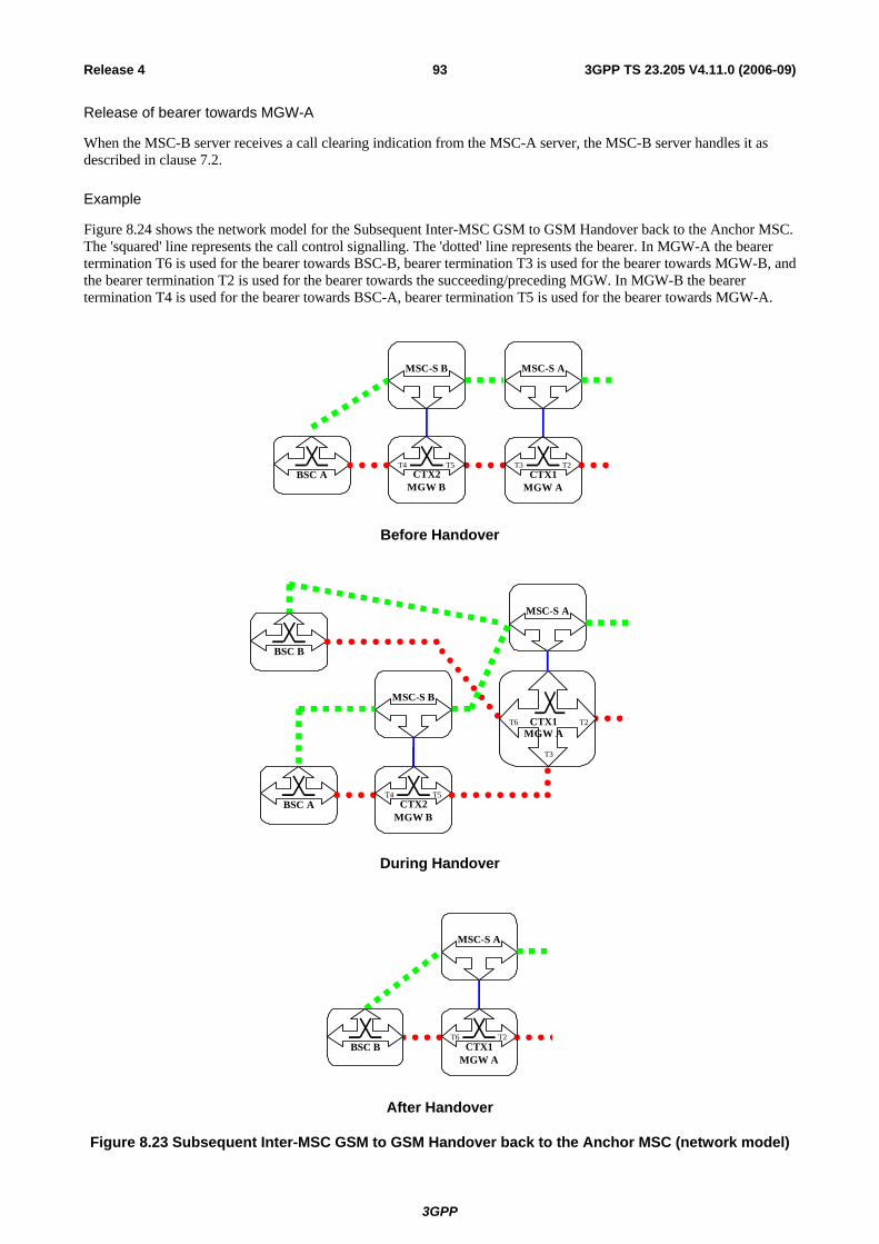
3GPP
3GPP TS 23.205 V4.11.0 (2006-09)93Release 4
Release of bearer towards MGW-A
When the MSC-B server receives a call clearing indication from the MSC-A server, the MSC-B server handles it as described in clause 7.2.
Example
Figure 8.24 shows the network model for the Subsequent Inter-MSC GSM to GSM Handover back to the Anchor MSC. The 'squared' line represents the call control signalling. The 'dotted' line represents the bearer. In MGW-A the bearer termination T6 is used for the bearer towards BSC-B, bearer termination T3 is used for the bearer towards MGW-B, and the bearer termination T2 is used for the bearer towards the succeeding/preceding MGW. In MGW-B the bearer termination T4 is used for the bearer towards BSC-A, bearer termination T5 is used for the bearer towards MGW-A.
MSC-S A
CTX1T3 T2
MGW ABSC A CTX2
T4 T5
MGW B
MSC-S B
Before Handover
MSC-S A
BSC B
CTX1MGW A
T6 T2
T3
BSC A CTX2T4 T5
MGW B
MSC-S B
During Handover
MSC-S A
CTX1T6 T2
MGW ABSC B
After Handover
Figure 8.23 Subsequent Inter-MSC GSM to GSM Handover back to the Anchor MSC (network model)

3GPP
3GPP TS 23.205 V4.11.0 (2006-09)94Release 4
Figure 8.24 shows the message sequence example for the Subsequent Inter-MSC GSM to GSM Handover back to the Anchor MSC. It is assumed that the Handover Device is located in the MGW (MGW-A) selected for the call establishment by the MSC server (MSC-A server) which controls the call and the mobility management.
In the example the MSC-A server requests MGW-A to seize BSC-B side bearer termination with specific flow directions. When the handover is detected in BSC-B the MSC-A server requests to change the flow directions between the terminations within the context in MGW-A. When MSC-A server receives Relocation Complete indication from BSC-B it transfers this indication to MSC-B server. MSC-B server releases the A-interface line towards the BSC-A. MSC-A server initiates call clearing towards MSC-B server.
MAP Prepare Subsequent Handover Req.
BSC B MGW A BSC AMSC-SA
A Handover Required
MSC-SB
MGW B
Context(C1) ADD.reply (T6)
A Handover Request
A Handover Request-Ack
Context(C1) ADD.request (T6)
Reserve Circuit
Context(C1) MOD.request (T2,T6,oneway)
Context(C1) MOD.reply (T2,T6)Change Flow Direction
Context(C1) MOD.request (T3,T6,isolate)
Context(C1) MOD.reply (T3,T6)Change Flow Direction
1
Figure 8.24/1 Subsequent Inter-MSC GSM to GSM Handover back to the Anchor MSC (message sequence chart)

3GPP
3GPP TS 23.205 V4.11.0 (2006-09)95Release 4
BSC B MGW A BSC AMSC A MGW B
MAP Send End Signal Resp.
A Handover Complete
MSC B
Handoverdetected in target
BSC
A Handover Detect
Context(C1) MOD.request (T2,T6,bothway)
Context(C1) MOD.reply (T2,T6)
Context(C1) MOD.request (T2,T3,oneway)
Context(C1) MOD.reply (T2,T3)
3 Change Flow Direction
Change Flow Direction
MAP Prepare Subsequent Handover Resp.
A Handover Command
A Clear Command
A Clear Complete
Context(C2) SUB.request (T4)
Context(C2) SUB.reply (T4)
4
Call Clearing and Bearer Release
Context(C1) MOD.request (T6)
Context(C1) MOD.reply (T6)Modify Bearer Characteristics(when applicable)
2
Figure 8.24/2 Subsequent Inter-MSC GSM to GSM Handover back to the Anchor MSC (message sequence chart)

3GPP
3GPP TS 23.205 V4.11.0 (2006-09)96Release 4
8.4.4 Subsequent GSM to GSM Handover to a third MSC The GSM to GSM handover to a third MSC server (from MSC-B server to MSC-B' server) is the combination of the two previous inter-MSC handover cases:
- for MSC-B server a subsequent GSM to GSM handover from MSC-B server back to MSC-A server as described in clause 8.4.3; and
- for MSC-B' server a basic GSM to GSM handover from MSC-A server to MSC-B' server as described in clause 8.4.2.
MSC-A server implements the corresponding parts of each handover case, i.e. access handling in MSC-A server is not included.
8.5 Handling of GSM Services after UMTS to GSM Handover The handling of GSM services after handover in the Bearer Independent CS Core Network architecture is as for the corresponding UMTS services, if not stated differently.
9 Compatibility Issues A Release 4 (or later) node, according to 3GPP TS 23.205, is backward compatible with a Release 99 (or earlier) node.
9.1 Interworking with GERAN (A i/f) The A-interface signalling terminates in the MSC server and the user plane terminates in the MGW. In the A-interface the only supported user plane is a TDM circuit. The MSC server uses the Mc interface to remotely control the TDM circuits in the MGW. Only one MSC server may control the TDM circuits connected to one GERAN node.
For each TDM circuit a physical termination is provisioned in the MGW. The TDM circuit is identified by the termination Id in the Mc interface. Since TDM circuits are also grouped together, the physical termination Ids are structured in accordance with the grouping of TDM circuits. The MSC server also knows the termination Ids and the grouping of termination Ids. The physical termination exists as long as the TDM circuit(s) exists in the MGW.
Figure 9.1 shows the network model for the A-interface. The 'squared' line represents the call control signalling and the 'dotted' line represents the TDM circuits. The terminations T1-Tn represent the TDM circuits in the MGW. The MSC server has a mapping table between circuits CIC1-CICn and the terminations T1-Tn.
MSC-S
T1Tn
CTX MGW
BSC
CIC1=T1CICn=Tn
Figure 9.1 TDM circuits used for A-interface (network model)
For call-independent transactions the general (G)MSC server-MGW procedures, as described in clause 10, apply to the physical terminations in the same way as to any other terminations.
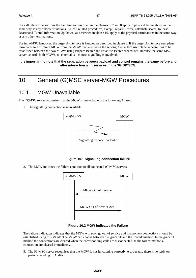
3GPP
3GPP TS 23.205 V4.11.0 (2006-09)97Release 4
For call related transactions the handling as described in the clauses 6, 7 and 8 apply to physical terminations in the same way as any other terminations. All call related procedures, except Prepare Bearer, Establish Bearer, Release Bearer and Tunnel Information Up/Down, as described in clause 16, apply to the physical terminations in the same way as any other terminations.
For intra-MSC handover, the target A-interface is handled as described in clause 8. If the target A-interface user plane terminates in a different MGW from the MGW that terminates the serving A-interface user plane, a bearer has to be established between the two MGWs using Prepare Bearer and Establish Bearer procedures. Because the same MSC server controls both MGWs, no external call control signalling is involved.
It is important to note that the separation between payload and control remains the same before and after interaction with services in the 3G BICSCN.
10 General (G)MSC server-MGW Procedures
10.1 MGW Unavailable The (G)MSC server recognises that the MGW is unavailable in the following 3 cases:
1. The signalling connection is unavailable
(G)MSC-S MGW
Signalling Connection Failure
Figure 10.1 Signalling connection failure
2. The MGW indicates the failure condition to all connected (G)MSC servers
MGW Out of Service Ack
MGW Out of Service
(G)MSC-S MGW
Figure 10.2 MGW indicates the Failure
The failure indication indicates that the MGW will soon go out of service and that no new connections should be established using this MGW. The MGW can choose between the 'graceful' and the 'forced' method. In the graceful method the connections are cleared when the corresponding calls are disconnected. In the forced method all connection are cleared immediately.
3. The (G)MSC server recognises that the MGW is not functioning correctly, e.g. because there is no reply on periodic sending of Audits.

3GPP
3GPP TS 23.205 V4.11.0 (2006-09)98Release 4
In all of the above cases the (G)MSC server shall prevent the usage of the MGW until the MGW has recovered or the communication with the MGW is restored. The (G)MSC server shall prohibit the surrounding network from seizing circuits connected to the unavailable TDM access by sending blocking messages.
10.2 MGW Available The (G)MSC server discovers that the MGW is available when it receives an MGW Communication Up message or an MGW Restoration message. When the (G)MSC server discovers that the MGW is available the following shall occur:
1. Signalling recovery
The MGW indicates to all connected (G)MSC servers that the signalling connection is restored.
MGW Communication Up Ack
MGW Communication Up
(G)MSC-S MGW
Signalling in service
Figure 10.3 Communication goes up
2. MGW restoration indication.
The MGW indicates to all connected (G)MSC servers that normal operation has resumed.
MGW Restoration Ack
MGW Restorationcold/warm boot
(G)MSC-S MGW
Signalling in service
Figure 10.4 MGW indicates recovery from a failure
NOTE: This procedure may be used after recovery from a signalling failure.
3. The (G)MSC server recognises that the MGW is now functioning correctly, e.g. because there is a reply on periodic sending of Audits.
After this the (G)MSC server can use the MGW. If the corresponding devices of the surrounding network are blocked, unblocked messages are sent to the nodes concerned.
If none of 1,2, and 3 happens the (G)MSC server can initiate the (G)MSC Server Ordered Re-register procedure.

3GPP
3GPP TS 23.205 V4.11.0 (2006-09)99Release 4
10.3 MGW Recovery If the MGW recovers from a failure or it has been restarted, it registers to its known (G)MSC servers using the MGW Restoration procedure. The MGW can indicate whether it has restarted with a cold or warm boot. The response sent to the MGW indicates a signalling address to be used by the MGW.
(Cold/Warm Boot)
(G)MSC-S address)
MGW Restoration Ack
MGW Restoration
(G)MSC-S MGW
Figure 10.5 MGW Restoration
After the recovery the (G)MSC server can use the MGW. If the corresponding devices of the surrounding network are blocked, unblocked messages are sent to the nodes concerned.
10.4 (G)MSC server Recovery
10.4.1 General If an MGW-unavailable condition is provoked by a failure/recovery action, the (G)MSC server recovery sequence will, from an information flow point of view, look like MGW unavailable and then MGW available. If an MGW-unavailable condition is not provoked, the (G)MSC server recovery sequence will look like MGW available.
After the information flow, the terminations affected by the recovery action are released.
10.4.2 (G)MSC Server Restoration
(G)MSC Server Restoration Ack
(G)MSC Server Restoration warm, cold ( boot) note
(G)MSC-S MGW
(G)MSC recovery complete
Tw
Signalling working
Communication Up/MGWRestoration
Communication Up/MGW Restoration Ack
Figure 10.6 (G)MSC Server Restoration

3GPP
3GPP TS 23.205 V4.11.0 (2006-09)100Release 4
Note: Normal release procedure may also be initiated
After the recovery action is complete and it is possible to signal to the MGW the (G)MSC server starts a timer Tw. If recovery indications are not received (MGW Communication Up or MGW Restoration) from the MGW during Tw an Audit is sent. If the (G)MSC server receives a recovery indication or MGW communication up indication, it shall acknowledge the indication before the (G)MSC Server Restoration may be sent or the release procedure is initiated.
10.5 MGW Re-register When the (G)MSC requests an MGW to perform a registration (see clause 10.11), the MGW performs a re-registration to the (G)MSC which is defined in the (G)MSC address.
MGW Re-register Ack
MGW Re-register
(G)MSC-S MGW
Figure 10-7 Re-registration of an MGW
10.6 MGW Re-registration Ordered by (G)MSC server If the (G)MSC server knows that communication is possible, but the MGW has not registered, the (G)MSC server can order re-registration of the MGW.
((G)MSC address)
Ack
(G)MSC-S MGW
(G)MSC Server Ordered Re-register
(G)MSC Server Ordered Re-register
Figure 10.8 Re-registration ordered by the (G)MSC server
If the re-registration request is accepted the MGW uses the MGW Register procedure to register with the (G)MSC server.
10.7 Removal from Service of a Physical Termination The MGW indicates the removal from service of a physical termination using the Termination Out-of-Service procedure. In this procedure the MGW indicates which termination is to be removed from service and whether the 'graceful' or 'forced' method will be used. In the graceful method a possible connection is cleared when the corresponding call is disconnected. In the forced method the possible connection is cleared immediately.
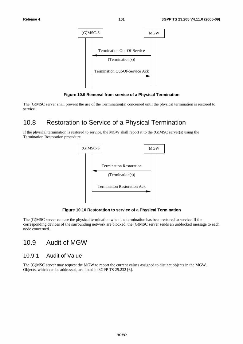
3GPP
3GPP TS 23.205 V4.11.0 (2006-09)101Release 4
(Termination(s))
Termination Out-Of-Service Ack
Termination Out-Of-Service
(G)MSC-S MGW
Figure 10.9 Removal from service of a Physical Termination
The (G)MSC server shall prevent the use of the Termination(s) concerned until the physical termination is restored to service.
10.8 Restoration to Service of a Physical Termination If the physical termination is restored to service, the MGW shall report it to the (G)MSC server(s) using the Termination Restoration procedure.
(Termination(s))
Termination Restoration Ack
Termination Restoration
(G)MSC-S MGW
Figure 10.10 Restoration to service of a Physical Termination
The (G)MSC server can use the physical termination when the termination has been restored to service. If the corresponding devices of the surrounding network are blocked, the (G)MSC server sends an unblocked message to each node concerned.
10.9 Audit of MGW
10.9.1 Audit of Value The (G)MSC server may request the MGW to report the current values assigned to distinct objects in the MGW. Objects, which can be addressed, are listed in 3GPP TS 29.232 [6].
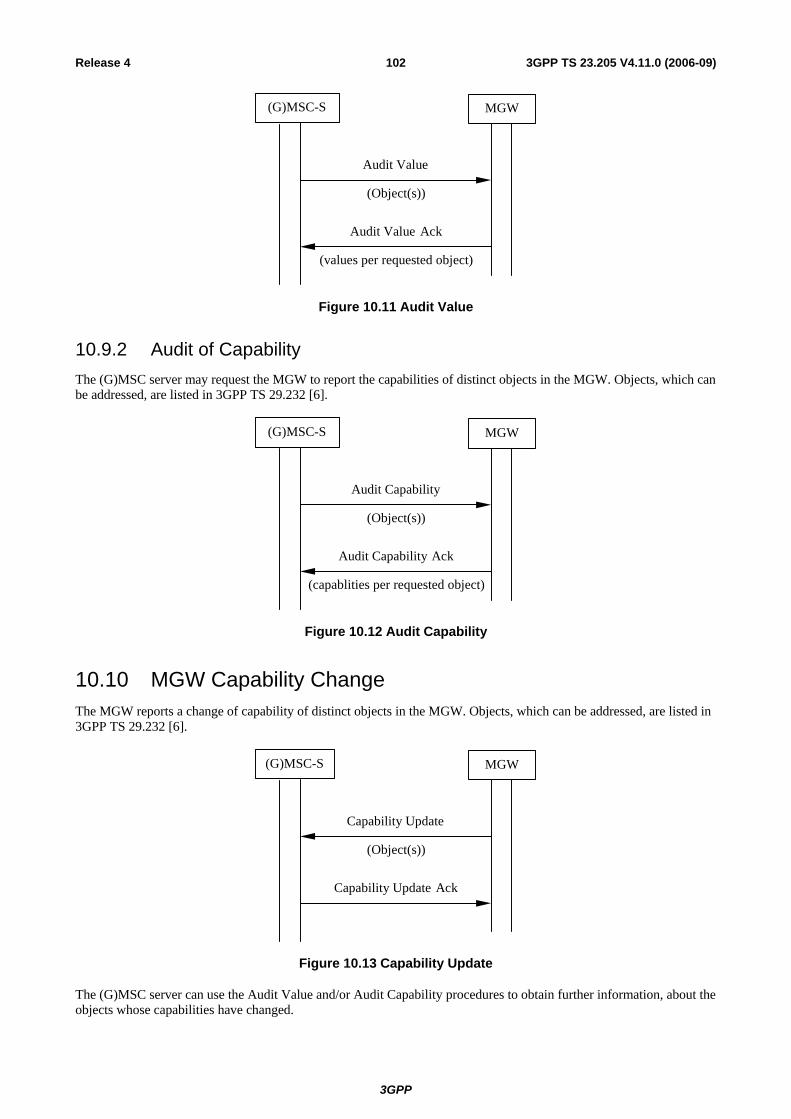
3GPP
3GPP TS 23.205 V4.11.0 (2006-09)102Release 4
(Object(s))
(values per requested object)
Audit Value Ack
Audit Value
(G)MSC-S MGW
Figure 10.11 Audit Value
10.9.2 Audit of Capability The (G)MSC server may request the MGW to report the capabilities of distinct objects in the MGW. Objects, which can be addressed, are listed in 3GPP TS 29.232 [6].
(Object(s))
(capablities per requested object)
Audit Capability Ack
Audit Capability
(G)MSC-S MGW
Figure 10.12 Audit Capability
10.10 MGW Capability Change The MGW reports a change of capability of distinct objects in the MGW. Objects, which can be addressed, are listed in 3GPP TS 29.232 [6].
(Object(s))
Capability Update Ack
Capability Update
(G)MSC-S MGW
Figure 10.13 Capability Update
The (G)MSC server can use the Audit Value and/or Audit Capability procedures to obtain further information, about the objects whose capabilities have changed.

3GPP
3GPP TS 23.205 V4.11.0 (2006-09)103Release 4
10.11 Void
10.12 (G)MSC Server Out of service
(Forced/graceful)
(G)MSC Server Out of Service Ack
(G)MSC Server Out of Service
(G)MSC-S MGW
Figure 10.15 (G)MSC Server Out of Service
If a (G)MSC server discovers that it wants to go out of service it starts a (G)MSC Server Out of Service procedure. The (G)MSC server can indicate whether it requires the context to be cleared immediately (forced) or cleared as the bearer control protocol clears the bearer (Graceful). Physical terminations are always cleared when the (G)MSC Server Out of Service indication reaches the MGW.
11 Identities
11.1 Bearer Address and Binding Reference The Bearer Address is exchanged on the Nc and Mc interfaces to identify the termination point of the bearer control signalling within the peer Media Gateway.
A Binding Reference is an identity, unique within the scope of one bearer control function, which identifies a bearer network connection. This information is exchanged on the Nc and Mc interfaces. The bearer control function is identified by the Bearer Address.
11.2 MGW-Id The Media Gateway Identity (MGW-Id) is information sent on the Nc interface to aid Media Gateway selection by the succeeding/preceding node.
The MGW-Id is bearer independent and it can be translated into a signalling address towards the appropriate MGW.
11.3 (G)MSC server Address The (G)MSC server Address defines the signalling address associated with the (G)MSC server that is used to interact with the Media Gateway over the Mc interface. This is a unique address in the network service supplier domain.
12 Operational Aspects
12.1 Charging No impacts.

3GPP
3GPP TS 23.205 V4.11.0 (2006-09)104Release 4
13 Interactions with Other Services NOTE1: All message sequence charts in this clause are informative examples.
NOTE2: The continuity indication in the IAM is not used to indicate that a continuity check will be performed on the current leg of the call, but it is used to indicate that a Continuity message can be expected as a result of a continuity check on a preceding ISUP circuit, or establishment of a preceding bearer connection.
13.1 enhanced Multi-Level Precedence and Pre-emption service (eMLPP)
No impact.
13.2 Call Deflection Service The procedures specified in 3GPP TS 23.072 [9] for the Call Deflection supplementary service shall be followed. The following paragraphs describe the additional requirements for the bearer independent CS core network.
MGW selection and incoming side bearer establishment
The MGW selected for the mobile terminating call is used. The incoming side bearer has already been established by the mobile terminating call procedures.
IU/A-interface release
If the call deflection request from a served subscriber is accepted the call towards the served mobile subscriber shall be released as described in the clause for call clearing.
Notification to the Calling Subscriber
If the served mobile subscriber has requested that the calling subscriber shall receive a notification about the call forwarding, a notification is sent to the calling party. If the notification is implemented using intermediate tones or announcements the MSC server requests the MGW to play an announcement/tone to the calling party, as described in clause 14.6, before establishing the call to the forwarded-to subscriber.
Initial addressing
The call towards the deflected-to subscriber is established as for basic call. If out-of-band transcoder control is applied for a speech call, it shall be performed in accordance with 3GPP TS 23.153 [3]. After the possible generation of in-band information has been completed the MSC server shall indicate in the IAM that forward or backward bearer establishment is to be used. The MSC server shall indicate in the IAM that no Continuity message will follow since the incoming bearer has already been established.
The MGW-id can be provided to the succeeding node in the IAM.
Establishment of bearer towards the forwarded-to subscriber
The bearer establishment towards the forwarded-to subscriber is performed as described for the mobile originating call, network side bearer establishment, using either forward or backward bearer establishment. The MSC server also requests the MGW to both-way through-connect the bearer.
Failure handling in MSC server
The failures are handled as described for the basic mobile originating call.

3GPP
3GPP TS 23.205 V4.11.0 (2006-09)105Release 4
Example
Figure 13.1 shows the network model for call deflection. The 'squared' line represents the call control signalling. The 'dotted' line represents the bearer control signalling and the bearer. Note that for a TDM access case there is no separation of call and bearer control signalling. The MSC server replaces the bearer termination for the served mobile subscriber (TB) with the bearer termination for the deflected-to subscriber (TC) in an existing context in the MGW. The bearer termination TA is used for the bearer towards the preceding MGW (calling subscriber).
MGW
MSC-S
CTXAB
TA TB
Before CD:
MGW
MSC-S
CTXAB
TA TC
After CD:
RNC/BSC
Figure 13.1: Call deflection (Network model)
Figure 13.2 shows the message sequence example for the call deflection with a possible notification to the calling party using an announcement. In the example, after the call and the bearer towards the access side have been released the MSC server requests the MGW to remove the bearer termination for the served mobile subscriber, and optionally requests the MGW to play an announcement and to notify the announcement completion. The MSC server shall request the establishment of the call towards the deflected-to subscriber after the possible announcement has completed.

3GPP
3GPP TS 23.205 V4.11.0 (2006-09)106Release 4
UEMGW RNC/BSCMSC-S
Mobile terminating call and bearer establishment
Context (CAB) SUB.reply (TB)
Context (CAB) SUB.request (TB)
Call and bearer release
OR1: YCall Progress
Call Deflection req
Call Deflection ack
Outgoing call and bearer establishment
NOTE: OR1: Notification to calling subscriber required (Y:yes N:no)
Playannounce
ment(TA)
Figure 13.2: Call deflection (message sequence chart)
13.3 Line identification Services
13.3.1 Calling Line Identification Presentation (CLIP) No impact.
13.3.2 Calling Line Identification Restriction (CLIR) No impact.
13.3.3 Connected Line Identification Presentation (COLP) No impact.
13.3.4 Connected Line Identification Restriction (COLR) No impact.

3GPP
3GPP TS 23.205 V4.11.0 (2006-09)107Release 4
13.4 Call Forwarding Services
13.4.1 Call Forwarding Unconditional (CFU) The procedures specified in 3GPP TS 23.082 [12] for the Call Forwarding Unconditional supplementary service shall be followed. The following paragraphs describe the additional requirements for the bearer independent CS core network.
MGW selection
If in-band information is to be provided to the calling subscriber the GMSC server shall select the MGW before providing the in-band information. The MGW selection can be based on a possibly received MGW-Id from the preceding node.
If in-band information is to not to be provided to the calling subscriber the GMSC server shall select the MGW for the bearer as described for the basic mobile terminating call.
Incoming side bearer establishment
The incoming side bearer establishment is handled in the GMSC server as described for the mobile terminating call using either forward or backward bearer establishment.
Notification to the Calling Subscriber
If the served mobile subscriber has requested that the calling subscriber shall receive a notification about the call forwarding, a notification is sent to the calling party. If the notification is implemented using intermediate tones or announcements the GMSC server requests the MGW to play an announcement/tone to the calling party, as described in clause 14.6, before establishing the call to the forwarded-to subscriber.
Initial addressing
If the incoming call is to be forwarded without being offered to the served mobile subscriber the call towards the forwarded-to subscriber is established as for a basic call. If out-of-band transcoder control is applied for a speech call, it shall be performed in accordance with 3GPP TS 23.153 [3]. After the possible generation of in-band information has been completed the initial addressing towards the forwarded-to subscriber is performed as described for the basic mobile terminating call indicating either forward or backward bearer establishment.
Establishment of bearer towards the forwarded-to subscriber
The bearer establishment towards the forwarded-to subscriber is performed as described for the mobile originating call, network side bearer establishment, using either forward or backward bearer establishment. The GMSC server also requests the MGW to both-way through-connect the bearer.
Confirmation of bearer establishment
The confirmation of the bearer establishment is handled as described for the basic mobile terminating call.
Failure handling in GMSC server
The failures are handled as described for the basic mobile terminating call.
Example
Figure 13.3 shows the network model for call forwarding unconditional. The 'squared' line represents the call control signalling. The 'dotted' line represents the bearer control signalling and the bearer. The GMSC server seizes one context with two bearer terminations in the MGW. The bearer termination TA is used for the bearer towards the preceding MGW (calling subscriber) and the bearer termination TC is used for the bearer towards the succeeding MGW (forwarded-to subscriber).

3GPP
3GPP TS 23.205 V4.11.0 (2006-09)108Release 4
GMSC-S
Before CFU:
MGW
GMSC-S
CTXAC
TA TC
After CFU:
Figure 13.3: CFU (Network model)
Figure 13.4 shows the message sequence example for the call forwarding unconditional with a possible notification to the calling party using an announcement. In the example the GMSC server optionally requests the MGW to play an announcement and to notify the announcement completion, after the bearer to the incoming side has been established. When the possible announcement has completed the GMSC server requests the establishment of the call and the bearer towards the forward-to subscriber.
GMSC-S MGW
Incoming call and bearer establishment
HLR interrogation
Address Complete
Outgoing call and bearer establishment
PlayAnnounce
ment(TA)
Figure 13.4: CFU (message sequence chart)
13.4.2 Call Forwarding on mobile subscriber Busy (CFB) The procedures specified in 3GPP TS 23.082 [12] for the Call Forwarding on Busy supplementary service shall be followed. The following paragraphs describe the additional requirements for the bearer independent CS core network.
13.4.2.1 Network Determined User Busy (NDUB)
If the mobile is Network Determined User Busy the incoming call for the specified basic service(s) shall be forwarded without being offered to the served mobile subscriber.
MGW selection
The MSC server shall select an MGW for the bearer connection either before sending the IAM or after receiving the Bearer Information message. If the MSC server received an MGW-id from the preceding node and/or from the succeeding node, then it may use one of them for the MGW selection.

3GPP
3GPP TS 23.205 V4.11.0 (2006-09)109Release 4
If in-band information is to be provided to the calling subscriber the MSC server shall select the MGW before providing the in-band information. The MGW selection can be based on a possibly received MGW-Id from the preceding node.
NOTE: As an implementation option, if there is no need for the MSC server to manipulate the bearer, the MSC server may only perform call control signalling without any associated MGW. In that case the bearer related information shall be provided transparently through the MSC server.
Incoming side bearer establishment
The incoming side bearer establishment is handled in the MSC server as described for the mobile terminating call using either forward or backward bearer establishment. The incoming side bearer establishment can take place either before or after the detection of NDUB condition.
Notification to the calling subscriber
If the served mobile subscriber has requested that the calling subscriber shall receive a notification about the call forwarding, a notification is sent to the calling party. If the notification is implemented using intermediate tones or announcements the MSC server requests the MGW to play an announcement/tone to the calling party, as described in clause 14.6, before establishing the call to the forwarded-to subscriber.
Initial addressing
The call towards the forwarded-to subscriber is established as for basic call. If out-of-band transcoder control is applied for a speech call, it shall be performed in accordance with 3GPP TS 23.153 [3]. After the possible generation of in-band information has been completed, the MSC server shall indicate in the IAM that the Continuity message will follow from the preceding node, in order to withhold the call completion until the establishment of the bearer is complete.
The MSC server shall indicate in the IAM that the Continuity message will follow from the preceding node if either of the following conditions is satisfied before sending the IAM:
1. The incoming IAM indicated that the Continuity message will follow, but no Continuity message has been received, or
2. The incoming side bearer has not been established.
If the MGW is selected at an early stage the MGW-id can be provided to the succeeding node in the IAM.
Establishment of bearer towards the forwarded-to subscriber
The bearer establishment towards the forwarded-to subscriber is performed as described for mobile originating call, network side bearer establishment, using either forward or backward bearer establishment. The MSC server also requests the MGW to both-way through-connect the bearer.
Confirmation of bearer establishment
If the outgoing IAM indicated that the Continuity message will follow, the Continuity message is sent when both of the following conditions are satisfied:
1. Either:
a. The incoming IAM indicated that the Continuity message will follow, and a Continuity message has been received, or
b. The incoming IAM did not indicate that the Continuity message will follow;
2. Either:
a. The MSC server has selected an MGW, and a notification indicating successful completion of the incoming side bearer set-up has been received from the MGW using the Bearer Established procedure, or
b. MGW selection is not requiered for this call.
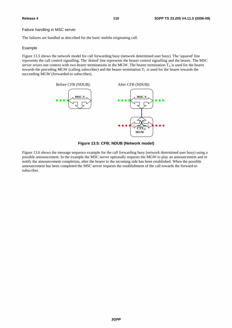
3GPP
3GPP TS 23.205 V4.11.0 (2006-09)110Release 4
Failure handling in MSC server
The failures are handled as described for the basic mobile originating call.
Example
Figure 13.5 shows the network model for call forwarding busy (network determined user busy). The 'squared' line represents the call control signalling. The 'dotted' line represents the bearer control signalling and the bearer. The MSC server seizes one context with two bearer terminations in the MGW. The bearer termination TA is used for the bearer towards the preceding MGW (calling subscriber) and the bearer termination TC is used for the bearer towards the succeeding MGW (forwarded-to subscriber).
MSC-S
Before CFB (NDUB):
MGW
MSC-S
CTXAC
TA TC
After CFB (NDUB):
Figure 13.5: CFB; NDUB (Network model)
Figure 13.6 shows the message sequence example for the call forwarding busy (network determined user busy) using a possible announcement. In the example the MSC server optionally requests the MGW to play an announcement and to notify the announcement completion, after the bearer to the incoming side has been established. When the possible announcement has been completed the MSC server requests the establishment of the call towards the forward-to subscriber.

3GPP
3GPP TS 23.205 V4.11.0 (2006-09)111Release 4
UEMGW RNC/BSC
MSC-S
Outgoing Call and Bearer Establishment
Address Complete
Incoming Call and Bearer Establishment
OR1: Y Notification
NOTE: OR1: Notification to forwarding subscriber required (Y: yes N: no) NDUB: Network Determined User Busy
NDUB
PlayAnnounce
ment(TA)
Figure 13.6: CFB (NDUB)
13.4.2.2 User Determined User Busy (UDUB)
MGW selection
The MGW selected for the mobile terminating call is used, if already selected by the mobile terminating call procedures.
The MSC server selects an MGW for the bearer either before sending the IAM of after receiving the Bearer Information message. If the MSC server received an MGW-id from the preceding node and/or from the succeeding node, then it may use one of them for the MGW selection.
If in-band information is to be provided to the calling subscriber the MSC server shall select the MGW before providing the in-band information. The MGW selection can be based on a possibly received MGW-Id from the preceding node.
NOTE: As an implementation option, if there is no need for the MSC server to manipulate the bearer, the MSC server may only perform call control signalling without any associated MGW. In that case the bearer related information shall be provided transparently through the MSC server.
Incoming side bearer establishment
For bearer establishment, the sending of bearer information is handled in the MSC server as described for the basic mobile terminating call indicating either forward or backward bearer establishment. The incoming side bearer establishment can take place either before or after the detection of UDUB condition.
IU/A-interface release
If the mobile is not Network Determined User Busy (NDUB as defined in GSM TS 02.01) the incoming call is offered (as a normal or waiting call) to the served mobile subscriber. If the mobile indicating 'User Busy' subsequently releases the call, the call towards the served mobile subscriber is released as described in the clause for call clearing. Note the MSC server orders the MGW to remove the bearer termination towards the served mobile subscriber only in the case where the radio resources had already been allocated in the MGW (bullet 1 in figure 13.8).

3GPP
3GPP TS 23.205 V4.11.0 (2006-09)112Release 4
Notification to the Calling Subscriber
If the served mobile subscriber has requested that the calling subscriber shall receive a notification about the call forwarding, a notification is sent to the calling party. If the notification is implemented using intermediate tones or announcements the MSC server requests the MGW to play an announcement/tone to the calling party as described in clause 14.6 before establishing the call to the forwarded-to subscriber.
Initial addressing
The call towards the forwarded-to subscriber is established as basic call. If out-of-band transcoder control is applied for a speech call, it shall be performed in accordance with 3GPP TS 23.153 [3]. After the possible generation of in-band information has been completed, the MSC server shall indicate in the IAM that the Continuity message will follow from the preceding node in order to withhold the call completion until the establishment of the bearer is complete.
The MSC server shall indicate in the IAM that the Continuity message will follow from the preceding node if either of the following conditions is satisfied before sending the IAM:
1. The incoming IAM indicated that the Continuity message will follow, but no Continuity message has been received, or
2. The incoming side bearer has not been established.
If the MGW is selected at an early stage the MGW-id can be provided to the succeeding node in the IAM.
Establishment of bearer towards the forwarded-to subscriber
The bearer establishment towards the forwarded-to subscriber is performed as described for the mobile originating call, network side bearer establishment, using either forward or backward bearer establishment. The MSC server also requests the MGW to both-way through-connect the bearer.
Confirmation of bearer establishment
If the outgoing IAM indicated that the Continuity message will follow, the Continuity message is sent when both of the following conditions are satisfied:
1. Either:
a. The incoming IAM indicated that the Continuity message will follow, and a Continuity message has been received from the preceding node (bullet 8 in figure 6.6), or
b. The incoming IAM did not indicate that the Continuity message will follow;
2. Either:
a. The MSC server has selected an MGW, and a notification of successful bearer establishment in the incoming side has been received from the MGW (bullet 7 in figure 6.6), or
b. MGW selection is not required for this call.
Failure handling in MSC server
The failures are handled as described for the basic mobile originating call.
Example
Figure 13.7 shows the network model for call forwarding busy (user determined user busy). The 'squared' line represents the call control signalling. The 'dotted' line represents the bearer control signalling and the bearer. Note that for a TDM access case there is no separation of call and bearer signalling. The MSC server replaces the bearer termination for the served mobile subscriber (TB) with the bearer termination for the forwarded-to subscriber (TC) in an existing context in the MGW. The bearer termination TA is used for the bearer towards the preceding MGW (calling subscriber).
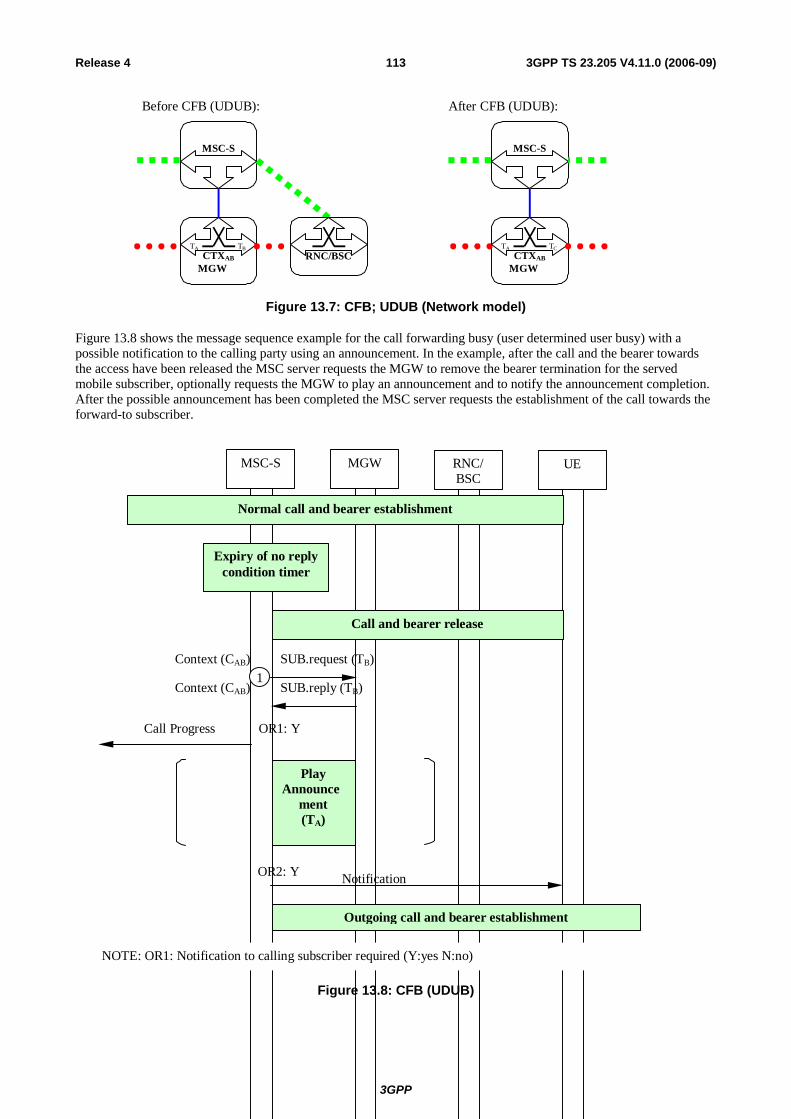
3GPP
3GPP TS 23.205 V4.11.0 (2006-09)113Release 4
MGW
MSC-S
CTXAB
TA TB
Before CFB (UDUB):
MGW
MSC-S
CTXAB
TA TC
After CFB (UDUB):
RNC/BSC
Figure 13.7: CFB; UDUB (Network model)
Figure 13.8 shows the message sequence example for the call forwarding busy (user determined user busy) with a possible notification to the calling party using an announcement. In the example, after the call and the bearer towards the access have been released the MSC server requests the MGW to remove the bearer termination for the served mobile subscriber, optionally requests the MGW to play an announcement and to notify the announcement completion. After the possible announcement has been completed the MSC server requests the establishment of the call towards the forward-to subscriber.
UEMGW RNC/BSC
MSC-S
Normal call and bearer establishment
Context (CAB) SUB.reply (TB)
Context (CAB) SUB.request (TB)
Call and bearer release
OR1: YCall Progress
NOTE: OR1: Notification to calling subscriber required (Y:yes N:no)
Expiry of no replycondition timer
Outgoing call and bearer establishment
Notification OR2: Y
1
PlayAnnounce
ment(TA)
Figure 13.8: CFB (UDUB)
3GPP
3GPP TS 23.205 V4.11.0 (2006-09)114Release 4
13.4.3 Call Forwarding on No Reply (CFNRy) The procedures specified in 3GPP TS 23.082 [12] for the Call Forwarding on No Reply supplementary service shall be followed. The following paragraphs describe the additional requirements for the bearer independent CS core network.
MGW selection and incoming side bearer establishment
The MGW selected for the mobile terminating call is used. The incoming side bearer has already been established by the mobile terminating call procedures.
IU/A-interface release
If the call is not answered within the period defined by the no reply condition timer the call towards the served mobile subscriber will be released as described in the clause for call clearing.
Notification to the Calling Subscriber
If the served mobile subscriber has requested that the calling subscriber shall receive a notification about the call forwarding, a notification is sent to the calling party. If the notification is implemented using intermediate tones or announcements the MSC server requests the MGW to play an announcement/tone to the calling party, as described in clause 14.6, before establishing the call to the forwarded-to subscriber.
Initial addressing
The call towards the forwarded-to subscriber is established as a basic call. If out-of-band transcoder control is applied for a speech call, it shall be performed in accordance with 3GPP TS 23.153 [3]. After the possible generation of in-band information has been completed (bullet 2 in figure 13.10) the MSC server shall indicate in the IAM that no Continuity message will follow from the preceding node because the incoming side bearer has already been established.
The MGW-id can be provided to the succeeding node in the IAM.
Establishment of bearer towards the forwarded-to subscriber
The bearer establishment towards the forwarded-to subscriber is performed as described for the mobile originating call, network side bearer establishment, using either forward or backward bearer establishment. The MSC server also requests the MGW to both-way through-connect the bearer.
Failure handling in MSC server
The failures are handled as described for the basic mobile originating call.
Example
Figure 13.9 shows the network model for call forwarding no reply. The 'squared' line represents the call control signalling. The 'dotted' line represents the bearer control signalling and the bearer. Note that for a TDM access case there is no separation of call and bearer control signalling. The MSC server replaces the bearer termination for the served mobile subscriber (TB) with the bearer termination for the forwarded-to subscriber (TC) in an existing context in the MGW. The bearer termination TA is used for the bearer towards the preceding MGW (calling subscriber).

3GPP
3GPP TS 23.205 V4.11.0 (2006-09)115Release 4
MGW
MSC-S
CTXAB
TA TB
Before CFNRy:
MGW
MSC-S
CTXAB
TA TC
After CFNRy:
RNC/BSC
Figure 13.9: CFNRy (Network model)
Figure 13.10 shows the message sequence example for the call forwarding on no reply with a possible announcement. In the example, after the call and the bearer towards the access have been released the MSC server requests the MGW to remove the bearer termination for the served mobile subscriber, and optionally requests the MGW to play an announcement and to notify the announcement completion. When the possible announcement has been completed the MSC server requests the establishment of the call towards the forward-to subscriber.

3GPP
3GPP TS 23.205 V4.11.0 (2006-09)116Release 4
UEMGW RNC/BSC
MSC-S
Normal call and bearer establishment
Context (CAB) SUB.reply (TB)
Context (CAB) SUB.request (TB)
Call and bearer release
OR1: YCall Progress
NOTE: OR1: Notification to calling subscriber required (Y:yes N:no)
Expiry of no replycondition timer
Outgoing Call and Bearer Establishment
Notification OR2: Y
PlayAnnounce
ment(TA)
Figure 13.10: CFNRy (message sequence chart)
13.4.4 Call Forwarding on mobile subscriber Not Reachable (CFNRc) The procedures specified in 3GPP TS 23.082 [12] for the Call Forwarding on Not Reachable supplementary service shall be followed. The following paragraphs describe the additional requirements for the bearer independent CS core network.
13.4.4.1 Rerouting by HLR
The same handling as for Call Forwarding Unconditional applies.
13.4.4.2 Rerouting by VLR
If the mobile is not reachable the incoming call for the specified basic service(s) will be forwarded without being offered to the served mobile subscriber.

3GPP
3GPP TS 23.205 V4.11.0 (2006-09)117Release 4
MGW selection
If in-band information is to be provided to the calling subscriber the MSC server shall select the MGW before providing the in-band information. The MGW selection can be based on a possibly received MGW-Id from the preceding node.
NOTE: As an implementation option, if in-band information is not to be provided to the calling subscriber the MSC server may either perform call control without any associated MGW, or reserve resources from an MGW and request bearer establishment through that MGW. In the latter case the MSC server selects an MGW for the bearer either before sending the IAM or after receiving the Bearer Information message. If the MSC server received an MGW-Id from the preceding node and/or from the succeeding node, those can be used for the MGW selection.
Incoming side bearer establishment
The incoming side bearer establishment is handled in the MSC server as described for the mobile terminating call, using either forward or backward bearer establishment. The incoming side bearer establishment can take place either before or after the detection of the not reachable condition.
Notification to the calling subscriber
If the served mobile subscriber has requested that the calling subscriber shall receive a notification about the call forwarding, a notification is sent to the calling party. If the notification is implemented using intermediate tones or announcements the MSC server requests the MGW to play an announcement/tone to the calling party, as described in clause 14.6, before establishing the call towards the forwarded-to party.
Initial addressing
The call towards the forwarded-to subscriber is established as a basic call. If out-of-band transcoder control is applied for a speech call, it shall be performed in accordance with 3GPP TS 23.153 [3]. After the possible generation of in-band information has been completed, the MSC server shall indicate in the IAM that the Continuity message will follow from the preceding node in order to withhold the call completion until the establishment of the bearer is complete.
The MSC server shall indicate in the IAM that the Continuity message will follow from the preceding node, if either of the following conditions is satisfied before sending the IAM:
1. The incoming IAM indicated that the Continuity message will follow, but no Continuity message has been received, or
2. The incoming side bearer has not been established.
If the MGW is selected at an early stage the MGW-id can be provided to the succeeding node in the IAM.
Establishment of bearer towards the forwarded-to subscriber
The bearer establishment towards the forwarded-to subscriber is performed as described for mobile originating call, network side bearer establishment, using either forward or backward bearer establishment. The MSC server also requests the MGW to both-way through-connect the bearer.
Confirmation of bearer establishment
If the outgoing IAM indicated that a Continuity message will follow, the Continuity message shall be sent when both of the following conditions are satisfied:
1. Either:
a. The incoming IAM indicated that the Continuity message will follow, and a Continuity message has been received, or
b. The incoming IAM did not indicate that the Continuity message will follow;
2. Either:
a. The MSC server has selected an MGW, and a notification indicating successful completion of the incoming side bearer set-up has been received from the MGW using the Bearer Established procedure, or

3GPP
3GPP TS 23.205 V4.11.0 (2006-09)118Release 4
b. MGW selection is not requiered for this call.
Failure handling in MSC server
The failures are handled as described for the basic mobile originating call.
Example
Figure 13.11 shows the network model for call forwarding on not reachable. The 'squared' line represents the call control signalling. The 'dotted' line represents the bearer control signalling and the bearer. The MSC server seizes one context with two bearer terminations in the MGW. The bearer termination TA is used for the bearer towards the preceding MGW (calling subscriber) and the bearer termination TC is used for the bearer towards the succeeding MGW (forwarded-to subscriber).
MSC-S
Before CFNRc:
MGW
MSC-S
CTXAC
TA TC
After CFNRc:
Figure 13.11: CFNRc; Rerouting by VLR (Network model)
Figure 13.12 shows the message sequence example for the call forwarding on not reachable with a possible announcement. In the example the MSC server optionally requests the MGW to play an announcement and to notify the announcement completion, after the bearer to the incoming side has been established. When the possible announcement has been completed the MSC server requests the establishment of the call towards the forward-to subscriber.
UEMGW RNC/BSC
MSC-S
Outgoing Call and Bearer Establishment
Address Complete
Incoming Call and Bearer Establishment
Mobile subscriber not reachable
PlayAnnounce
ment(TA)
Figure 13.12: CFNRc (Rerouting by VLR) (message sequence chart)

3GPP
3GPP TS 23.205 V4.11.0 (2006-09)119Release 4
13.5 Call Waiting (CW) The procedures specified in 3GPP TS 23.083 [13] for the Call Waiting supplementary service shall be followed. The following paragraphs describe the additional requirements for the bearer independent CS core network.
Call confirmation to the waiting call
The MSC server shall, on reception of the call confirmation, select the MGW that will be used for the waiting call. The MSC server should select the MGW which is already in use for the active call. If out-of-band transcoder control is applied for the waiting speech call, it shall be performed in accordance with 3GPP TS 23.153 [3].
Existing call on hold
The paragraph 'Hold request' in clause 13.6 applies.
Existing call released
If the active call is disconnected while another call is waiting, the bearer termination towards the waiting party (C) as well as to the called party (A) is not removed.
Acceptance of waiting call
If the mobile subscriber decides to accept the waiting call, it handles (according to 3GPP TS 23.083 [12]) the existing call as described in clause 13.5 (i.e. it either puts the call on hold or the call is released). When the MSC server receives the connect indication from subscriber A, if required the MSC server shall modify the access bearer as described in subclause 13.18.1. Finally, the MSC server shall connect the access side bearer termination to the previously created bearer termination of the remote party in the waiting call and modify the waiting call's bearer termination so that it is both-way through-connected.
If a different MGW is selected for the incoming call, then a bearer from the new MGW (MGW2) shall be connected towards the old MGW (MGW1) before offering the call to the subscriber A.
If out-of-band transcoder control is applied for the waiting speech call, it shall be performed in accordance with 3GPP TS 23.153[3].
Waiting call released by calling subscriber (subscriber C)
The respective resources already allocated at the selected MGW for the waiting call shall be released.
Example
Figure 13.13 shows the network model for a waiting call at the serving MSC server/MGW. The 'thick, squared' line represents the call control signalling for the existing call and, on the Iu interface, the already existing control plane toward the serving RNC. The 'thin, squared' line represents the call control signalling for the waiting call. The 'thick, dotted' line represents the bearer control signalling and the bearer for the existing call, whereas the 'thin, dotted' line represents the ones for the waiting call. Note that for a TDM access there is no separation of call and bearer control signalling.
Note that there shall be only one instance of bearer resource/bearer control signalling on the radio side.
If the CW condition applies, the MSC server seizes a new context with one bearer termination, TC, in the MGW. TA and TB are the terminations of the already existing call.

3GPP
3GPP TS 23.205 V4.11.0 (2006-09)120Release 4
MGW
MSC-S
RNC/BSC
CTX2(... -C)
TC
CTX1(A-B)
TA TB
B party
C party
one MGW involved: two MGWs involved: MSC-S
B party
C party
MGW2
CTX3(... -
TC
RNC/BSC
MGW1
CTX1(A-B)
TA TB
CTX2(... -C)
TC
Figure 13.13. Call Wait (network model)
13.5.1 Call Confirmation of the waiting call Figure 13.14 shows the sequence chart for the actions necessary within the bearer independent CS core network during call confirmation of the waiting call. Call and bearer establishment shall be as described for the mobile terminating call. When the MSC server receives the Alerting indication from the called subscriber (subscriber A), it shall apply the ringing tone to the waiting termination (TC).
UE RNC/BSC
MSC-S MGW
SETUP A-C
Context (C2) MOD.request(TC)
Context (C2) MOD.reply(TC)
Address Complete
CALL CONFIRMED A-C (A=busy)
Apply Tone
Call and Bearer establishment C ⇒ A
ALERTING A-C
active call A-B
Figure 13.14. Call Confirmation of the Waiting Call.

3GPP
3GPP TS 23.205 V4.11.0 (2006-09)121Release 4
13.5.2 Acceptance of the Waiting Call Figure 13.15 shows the sequence chart for the actions necessary within the bearer independent CS core network for the acceptance of a waiting call. When the MSC server receives the Connect indication from the UE (subscriber A) (bullet 1 in figure 13.15), it shall request the MGW to disconnect subscriber C from the applied ringing tone (bullet 2 in figure 13.15) and move TA to the context of the waiting call (bullet 3 in figure 13.15). The MSC server then requests the MGW to change the through-connection of the termination TC so that it will be bothway through-connected (bullet 4 in figure 13.15).
UE RNC/BSC
MSC-S MGW
CONNECT A-C
Answer
CONNECT ACK A-C
1
5
B on hold, C waiting
Context (C2) MOD.request(TC)
Context (C2) MOD.reply(TC)Disconnect TC fromAnnouncement/Tone
2
Context (C2) MOVE.request(TA)
Context (C2) MOVE.reply(TA) Move TA to C23
Context (C2) MOVE.request(TC)
Context (C2) MOVE.reply(TC)Change TC’s Flow directionto bothway
4
Figure 13.15. Acceptance of the Waiting Call.
13.6 Call Hold (CH) The procedures specified in 3GPP TS 23.083 [13] for the Call Hold supplementary service shall be followed. The following paragraphs describe the additional requirements for the bearer independent CS core network.
Hold request
When the UE makes a request for the hold function the MSC server requests the MGW to interrupt the communication on the bearer by changing the through-connection of the bearer termination towards the served mobile subscriber to 'not through-connected'. Announcements may be applied to the held party as described in clause 14.6.
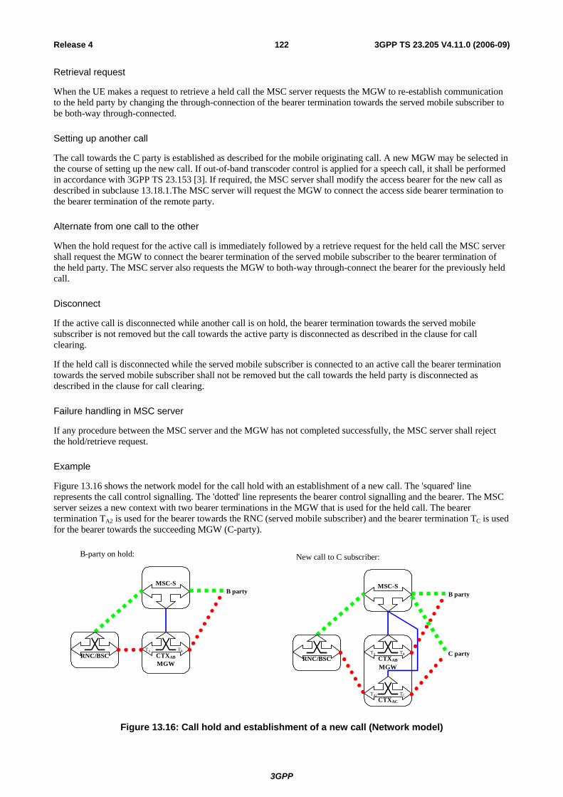
3GPP
3GPP TS 23.205 V4.11.0 (2006-09)122Release 4
Retrieval request
When the UE makes a request to retrieve a held call the MSC server requests the MGW to re-establish communication to the held party by changing the through-connection of the bearer termination towards the served mobile subscriber to be both-way through-connected.
Setting up another call
The call towards the C party is established as described for the mobile originating call. A new MGW may be selected in the course of setting up the new call. If out-of-band transcoder control is applied for a speech call, it shall be performed in accordance with 3GPP TS 23.153 [3]. If required, the MSC server shall modify the access bearer for the new call as described in subclause 13.18.1.The MSC server will request the MGW to connect the access side bearer termination to the bearer termination of the remote party.
Alternate from one call to the other
When the hold request for the active call is immediately followed by a retrieve request for the held call the MSC server shall request the MGW to connect the bearer termination of the served mobile subscriber to the bearer termination of the held party. The MSC server also requests the MGW to both-way through-connect the bearer for the previously held call.
Disconnect
If the active call is disconnected while another call is on hold, the bearer termination towards the served mobile subscriber is not removed but the call towards the active party is disconnected as described in the clause for call clearing.
If the held call is disconnected while the served mobile subscriber is connected to an active call the bearer termination towards the served mobile subscriber shall not be removed but the call towards the held party is disconnected as described in the clause for call clearing.
Failure handling in MSC server
If any procedure between the MSC server and the MGW has not completed successfully, the MSC server shall reject the hold/retrieve request.
Example
Figure 13.16 shows the network model for the call hold with an establishment of a new call. The 'squared' line represents the call control signalling. The 'dotted' line represents the bearer control signalling and the bearer. The MSC server seizes a new context with two bearer terminations in the MGW that is used for the held call. The bearer termination TA2 is used for the bearer towards the RNC (served mobile subscriber) and the bearer termination TC is used for the bearer towards the succeeding MGW (C-party).
MGW
MSC-S
CTXAB
TB
RNC/BSC
B party
TA
B-party on hold:
MGW
MSC-S
CTXAB
TB
RNC/BSC
CTXAC
TA2 TC
B party
C party
New call to C subscriber:
TA
Figure 13.16: Call hold and establishment of a new call (Network model)

3GPP
3GPP TS 23.205 V4.11.0 (2006-09)123Release 4
Figure 13.17 shows the message sequence example for the call hold procedure. In the example the MSC server requests the MGW to change the through-connection of the bearer so that it will not be through-connected when the hold request is received from the served mobile subscriber (bullet 2 in figure 13.17). Subsequently an announcement may be applied to termination TA.
UE RNC/BSC
MSC-S MGW
HOLD
Context (CAB) MOD.request(TB)
Context (CAB) MOD.reply(TB)
Call ProgressHOLD ACK
Change Through-Connection
1
2
3
MSC acceptsHold Request
PlayAnnouncement
(TB)
Figure 13.17: Hold request (message sequence chart)
Figure 13.18 shows the message sequence example for the retrieval procedure. In the example the MSC server requests the MGW to change the through-connection of the bearer to be both-way through-connected (bullet 3 in figure 13.18) after the held party has been disconnected from an optionally applied announcement (bullet 2 in figure 13.18).
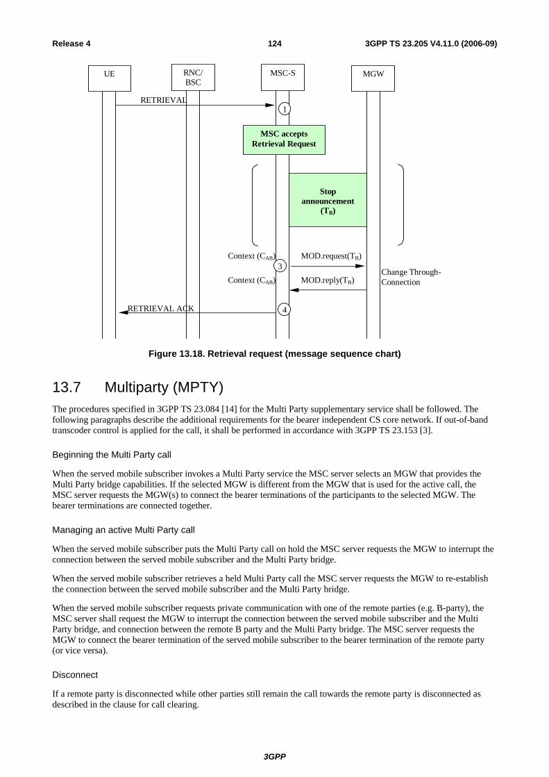
3GPP
3GPP TS 23.205 V4.11.0 (2006-09)124Release 4
RETRIEVAL
RETRIEVAL ACK
Context (CAB) MOD.request(TB)
Context (CAB) MOD.reply(TB)Change Through-Connection
1
3
4
UE RNC/BSC
MSC-S MGW
MSC acceptsRetrieval Request
Stopannouncement
(TB)
Figure 13.18. Retrieval request (message sequence chart)
13.7 Multiparty (MPTY) The procedures specified in 3GPP TS 23.084 [14] for the Multi Party supplementary service shall be followed. The following paragraphs describe the additional requirements for the bearer independent CS core network. If out-of-band transcoder control is applied for the call, it shall be performed in accordance with 3GPP TS 23.153 [3].
Beginning the Multi Party call
When the served mobile subscriber invokes a Multi Party service the MSC server selects an MGW that provides the Multi Party bridge capabilities. If the selected MGW is different from the MGW that is used for the active call, the MSC server requests the MGW(s) to connect the bearer terminations of the participants to the selected MGW. The bearer terminations are connected together.
Managing an active Multi Party call
When the served mobile subscriber puts the Multi Party call on hold the MSC server requests the MGW to interrupt the connection between the served mobile subscriber and the Multi Party bridge.
When the served mobile subscriber retrieves a held Multi Party call the MSC server requests the MGW to re-establish the connection between the served mobile subscriber and the Multi Party bridge.
When the served mobile subscriber requests private communication with one of the remote parties (e.g. B-party), the MSC server shall request the MGW to interrupt the connection between the served mobile subscriber and the Multi Party bridge, and connection between the remote B party and the Multi Party bridge. The MSC server requests the MGW to connect the bearer termination of the served mobile subscriber to the bearer termination of the remote party (or vice versa).
Disconnect
If a remote party is disconnected while other parties still remain the call towards the remote party is disconnected as described in the clause for call clearing.

3GPP
3GPP TS 23.205 V4.11.0 (2006-09)125Release 4
Failure handling in MSC server
If resources for the Multi Party service cannot be allocated in any of the MGW resources assigned to the MSC server, then the MSC server shall reject the MPTY request.
Example 1
Figure 13.19 shows the network model for multi party call. The 'squared' line represents the call control signalling. The 'dotted' line represents the bearer control signalling and the bearer. Note that for a TDM access there is no separation between the call and bearer control signalling. In the following example it is assumed that each party participating in the Multi Party conference is handled in a separate context representing the call leg between the Multi Party bridge and the Multi Party participant. The Multi Party bridge itself is handled in a separate context. This separation to several contexts is done in order to simplify interactions with other functionality, such as handover, even though other implementation options are not excluded.
MSC-S
MGW
CTXMPTYTA0 TB0
TC0
RNC/BSC CTXA
TACTXAB
TB1 TC
CTXAC
TB1 TB
TA1 B-party
C party
Figure 13.19: Multi Party call (Network model)
For the purposes of the information flow diagrams it is assumed that there are only two remote parties. Party A is the subscriber controlling the Multi Party service (served mobile subscriber). Party B is the held party and party C is the active party.
It is assumed that the Multi Party bridge is located in the MGW that has been selected for the served mobile subscriber.
Figure 13.20 shows the message sequence example for the beginning of multi party call. When the served mobile subscriber invokes a Multi Party service the MSC server requests the MGW to create a separate context for the Multi Party bridge. The MSC server seizes a bearer termination for each party in that context. In addition, each call leg is represented by a separate context. Therefore the parties in the active call will be split in separate contexts. The MSC server requests the MGW to create a new context and to move the bearer termination for the served mobile subscriber from the active call context to the new context. To connect the parties to the Multi Party bridge the MSC server requests the MGW to establish internal connections between the bearer terminations in the Multi Party bridge context and the call leg contexts. The held party is informed about the retrieval of the held call, and the both remote parties are informed about the multi party call establishment.

3GPP
3GPP TS 23.205 V4.11.0 (2006-09)126Release 4
UE RNC/BSC MSC-S MGW
Multi Party req
Context ($) ADD.request ($) ADD.request ($) ADD.request ($)
Context (CMPTY) ADD.reply (TA0) ADD.reply (TB0) ADD.reply (TC0)
Context (CA) MOV.reply (TA)
Context ($) MOV.request (TA)
Context (CAB) ADD.request ($)
Call Progress (to B)
Multi Party acknowledge
Context (CAB) ADD.reply (TB1)
Context (CAC) ADD.request ($)
Context (CAC) ADD.reply (TC1)
Call Progress (to B)
Call Progress (to C)
Context (CA) ADD.reply (TA1)
Context (CA) ADD.request ($)
Prepare bearerPrepare bearerPrepare bearer
Establish bearer
Establish bearer
Establish bearer
Figure 13.20: Information flow for multi party call (message sequence chart)
Example 2
The figure 13.21 below shows the network model for multi party call. The 'squared' line represents the call control signalling. The 'dotted' line represents the bearer control signalling and the bearer. In the following example it is assumed that all parties are handled together within a Multi Party context during Multi Party operation.

3GPP
3GPP TS 23.205 V4.11.0 (2006-09)127Release 4
MSC-S
MGW
CTXATA TB
TC
RNCB-party
C party
Figure 13.21: Multi Party call (Network model)
For the purposes of the information flow diagrams it is assumed that there are only two remote parties. Party A is the subscriber controlling the Multi Party service (served mobile subscriber). Party B is the held party and party C is the active party.
It is assumed that the Multi Party bridge is located in the MGW and an active context that has been selected for the served mobile subscriber.
The figure 13.22 below shows the message sequence example for the beginning of multi party call. When the served mobile subscriber invokes a Multi Party service the MSC server requests the MGW to move the bearer termination for the held party into the active context. The held party is informed about the retrieval of the held call, and both remote parties are informed about the multi party call establishment.
UE RNC MSC-S MGW
Multi Party req
Context (C1) MOVE.request (TB)
Context (C1) MOVE.reply (TB)
Call Progress (Retrieved) (to B)
Multi Party acknowledge
Call Progress (Multiparty) (to B)
Call Progress (Multiparty) (to C)
Figure 13.22: Information flow for multi party call (message sequence chart)
3GPP
3GPP TS 23.205 V4.11.0 (2006-09)128Release 4
13.8 Closed User Group (CUG) No impact.
13.9 Advice of Charge (AoC) No impact.
13.10 User-to-User Signalling (UUS) No impact.
13.11 Call Barring Services
13.11.1 Barring of outgoing calls No impact.
13.11.2 Barring of incoming calls No impact.
13.12 Explicit Call Transfer (ECT) The procedures specified in 3GPP TS 23.091 [15] for the Explicit Call Transfer supplementary service shall be followed. The following paragraphs describe the additional requirements for the bearer independent CS core network.
Party A is the subscriber controlling the Explicit Call Transfer Call (served mobile subscriber). Party B is the first remote called party (held party). Party C is the second remote called party.
Connection of remote parties
If the result of the ECT checks is successful the MSC server will order the MGW to connect the bearer termination of the C-party to the bearer termination of the B-party (bullet 1 in figure 13.24 or in figure 13.21). As a result of this action the held party will be retrieved.
If the call towards the C-party has not been answered, the MSC server requests the MGW to both-way through-connect the bearer termination towards the C-party.
IU/A-interface release
The served party is disconnected after a successful transfer request. The call towards the served mobile subscriber shall be released as described in the clause for call clearing.
Failure handling in MSC server
If the bearer terminations for the remote parties can not be connected successfully, the MSC server shall reject the ECT request.
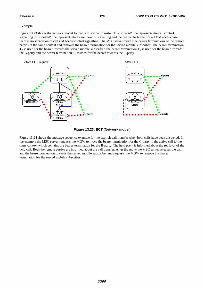
3GPP
3GPP TS 23.205 V4.11.0 (2006-09)129Release 4
Example
Figure 13.23 shows the network model for call explicit call transfer. The 'squared' line represents the call control signalling. The 'dotted' line represents the bearer control signalling and the bearer. Note that for a TDM access case there is no separation of call and bearer control signalling. The MSC server moves the bearer terminations of the remote parties in the same context and removes the bearer termination for the served mobile subscriber. The bearer termination TA is used for the bearer towards the served mobile subscriber, the bearer termination TB is used for the bearer towards the B-party and the bearer termination TC is used for the bearer towards the C-party.
MGW
MSC-S
CTXAB
TB
RNC/BSC
CTXAC
TC
B party
C partyTA
Before ECT request:
MGW
MSC-S
CTXAB
TBTC
B party
C party
After ECT:
Figure 13.23: ECT (Network model)
Figure 13.24 shows the message sequence example for the explicit call transfer when both calls have been answered. In the example the MSC server requests the MGW to move the bearer termination for the C-party in the active call to the same context which contains the bearer termination for the B-party. The held party is informed about the retrieval of the held call. Both the remote parties are informed about the call transfer. After the move the MSC server releases the call and the bearer connection towards the served mobile subscriber and requests the MGW to remove the bearer termination for the served mobile subscriber.

3GPP
3GPP TS 23.205 V4.11.0 (2006-09)130Release 4
UE RNC/BSC MSC-S MGW
ECT req
ECT acknowledge
Call progress (to B)
A-B active, held / A-C active, idle
Call and bearer release
Call Progress (to B)
Call Progress (to C)
Context (CAC) SUB.request (TA)
Context (CAC) SUB.reply (TA)
Context (CAB) MOV.request (TC)
Context (CAB) MOV.reply (TC)1
Release Termination
Figure 13.24: Explicit call transfer; both calls answered (message sequence chart)
Figure 13.25 shows the message sequence example for the explicit call transfer when one call is answered and the other call has been delivered. In the example the MSC server requests the MGW to move the bearer termination for the C-party in the active call to the same context which contains the bearer termination for the B-party. The held party is informed about the retrieval of the held call. Both the remote parties are informed about the call transfer. After the move the MSC server releases the call and the bearer connection towards the served mobile subscriber and requests the MGW to remove the bearer termination for the served mobile subscriber. The B-party is informed about the active call when the C-party sends the Answer indication.

3GPP
3GPP TS 23.205 V4.11.0 (2006-09)131Release 4
Context (CAB) MOV.request (TC)
UE RNC/BSC MSC-S MGW
ECT req
ECT acknowledge
Context (CAB) MOV.reply (TC)
Call Progress (to B)
A-B active, held / A-C active, delivered
Call and bearer release
Call Progress (to B)
Call Progress (to C)
Context (CAC) SUB.request (TA)
Context (CAC) SUB.reply (TA)
Answer (from C)
Call Progress (to B)
1
Release Termination
Figure 13.25: Explicit call transfer; other call delivered (message sequence chart)
13.13 Completion of Calls to Busy Subscriber (CCBS) The procedures specified in 3GPP TS 23.093 [16] for the Completion of Calls to Busy Subscriber supplementary service and 3GPP TS 23.108 [18] shall be followed. The following paragraphs describe the additional requirements for the bearer independent CS core network.
13.13.1 Clearing when tones/announcements are provided to the calling subscriber
If an announcement is to be provided for the purpose of notifying the subscriber that CCBS activation is possible, the MSC server shall select an MGW. The MGW performs the traffic channel assignment if the bearer termination has not been through-connected (as described in clause 6.1 for the basic mobile originating call). The MGW through-connects the bearer before providing the in-band information. The MSC server requests the MGW to play an announcement/tone using the Play Announcement or Send Tone procedure. When the announcement has completed the MGW notifies the MSC server (using the Announcement Completed procedure as described in clause 14.6) that the announcement is complete.
Otherwise the MSC server handles the call clearing as described in clause 7.
13.13.2 Network initiated mobile originated call The call is established as described in clause 6.1 for basic mobile originating call.
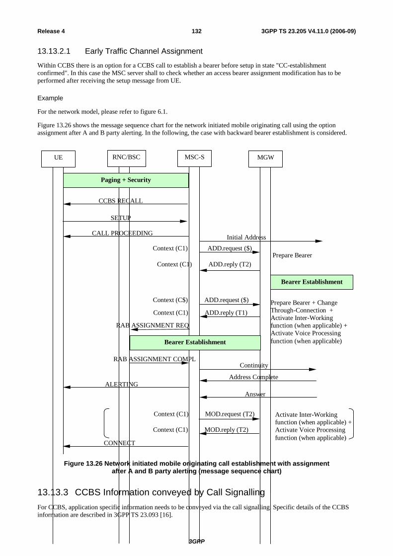
3GPP
3GPP TS 23.205 V4.11.0 (2006-09)132Release 4
13.13.2.1 Early Traffic Channel Assignment
Within CCBS there is an option for a CCBS call to establish a bearer before setup in state "CC-establishment confirmed". In this case the MSC server shall to check whether an access bearer assignment modification has to be performed after receiving the setup message from UE.
Example
For the network model, please refer to figure 6.1.
Figure 13.26 shows the message sequence chart for the network initiated mobile originating call using the option assignment after A and B party alerting. In the following, the case with backward bearer establishment is considered.
Activate Inter-Workingfunction (when applicable) +Activate Voice Processingfunction (when applicable)
Context (C1) MOD.reply (T2)
Context (C1) MOD.request (T2)
CONNECT
ALERTINGAnswer
Address Complete
CALL PROCEEDING
SETUP
Initial Address
Bearer Establishment
UE RNC MSC MGWUE RNC/BSC MSC-S MGW
Context (C1) ADD.reply (T1)
Context (C$) ADD.request ($)
RAB ASSIGNMENT REQ
RAB ASSIGNMENT COMPL
Bearer Establishment
Prepare Bearer + ChangeThrough-Connection +Activate Inter-Workingfunction (when applicable) +Activate Voice Processingfunction (when applicable)
Context (C1) ADD.reply (T2)
Context (C1) ADD.request ($)Prepare Bearer
Paging + Security
CCBS RECALL
Continuity
Figure 13.26 Network initiated mobile originating call establishment with assignment after A and B party alerting (message sequence chart)
13.13.3 CCBS Information conveyed by Call Signalling For CCBS, application specific information needs to be conveyed via the call signalling. Specific details of the CCBS information are described in 3GPP TS 23.093 [16].

3GPP
3GPP TS 23.205 V4.11.0 (2006-09)133Release 4
13.14 Multiple Subscriber Profile (MSP) No impact.
13.15 Multicall The procedures specified in 3GPP TS 23.135 [17] for the Multicall supplementary service shall be followed. The following paragraphs describe the additional requirements for the bearer independent CS core network. If out-of-band transcoder control is applied for a speech call, it shall be performed in accordance with 3GPP TS 23.153 [3].
Mobile Originating
When the UE is in active mode and it makes a request for the multicall function on a new traffic channel, call and bearer establishment shall be as described for mobile originating call.
When the UE is in active mode and it makes a request for the multicall function using an existing traffic channel, call and bearer establishment shall be as described for call hold function. An active call will be placed on hold and the additional originating call will be initiated.
Mobile Terminating
When the UE is in active mode and it makes a request for the multicall function on a new traffic channel, call and bearer establishment shall be as described for mobile terminating call. Access bearer assignment shall occur either after a Call Confirmed or a Connect message is received from the UE.
When the UE is in active mode and it makes a request for the multicall function using an existing traffic channel, call and bearer establishment shall be as described for call hold function. An active call will be placed on hold and the additional terminating call will be initiated.
13.16 Calling Name Presentation (CNAP) No impact.
13.17 Alternate Speech/Fax The procedures for facsimile group 3 transparent/non-transparent shall be followed in accordance with GSM TS 03.45 [24] and 3GPP TS 23.146 [25]. The following paragraphs describe the additional requirements for the bearer independent CS core network. If out-of-band transcoder control is applied for a speech call, it shall be performed in accordance with 3GPP TS 23.153 [3].
Call and bearer establishment shall be handled as described in the Call Establishment clause. In order to change from speech to fax (or vice versa), the MSC server shall modify the access bearer as described in subclause 13.18.1.
If the MGW responds with an error to any of the procedures initiated by the MSC server, or the MSC server receives a Bearer Failure procedure from the MGW, the MSC server may either clear the call or reject the change from speech to fax (or vice versa).
After this possible modification, the MGW shall seize an interworking function if a PLMN Bearer Capability [4] has been supplied to the access side bearer termination. When the MSC server receives an answer indication, it shall request activation of the interworking function using the Activate Interworking Function procedure.
13.18 Modification of the Access Bearer
13.18.1 Modification of Bearer Characteristics The modification of the access bearer is possible during a call establishment and during an active call. If the MSC server needs to modify the access bearer, the existing access side bearer termination in the MGW is modified or a new
3GPP
3GPP TS 23.205 V4.11.0 (2006-09)134Release 4
access side bearer termination is created. The modification of the access bearer shall be performed in accordance with 3GPP TS 25.413 [26] or 3GPP TS 48.008 [27].
UTRAN
If the link characteristics for the existing access bearer need to be changed and the MSC server previously received a notification from the MGW that modification of link characteristics of the current transport connection is supported [refer to 26], the MSC server shall use the Modify Bearer Characteristics procedure to provide the MGW with the new bearer characteristics for the existing access side bearer termination. After the MGW has replied, the MSC server shall initiate the access bearer modification towards UTRAN.
If the MSC server has not previously received a notification from the MGW that modification of existing link characteristics is supported, the MSC server shall use the Prepare Bearer procedure to request the MGW to add a new context and a new access side bearer termination, and to provide a bearer address and a binding reference. After the MGW has replied, the MSC server shall initiate the access bearer modification towards UTRAN using the provided bearer address and the binding reference. Upon successful access bearer modification, the MSC server shall connect the new access side bearer termination to the old context and release the old access side bearer termination.
If the user plane mode of the modified access bearer is ‘Support Mode’, the Iu UP will also be re-initialised as defined in [20].
GERAN
The MSC server shall use the Modify Bearer Characteristics procedure to the MGW to provide the new bearer characteristics for the existing access side bearer termination. After the MGW has replied, the MSC server shall initiate the access bearer modification towards GERAN.
13.18.2 IWF Protocol Change If the MSC server has requested indication on IWF protocol events, the MGW informs the MSC server about changes related to IWF protocol, using the IWF Protocol Indication procedure.
13.19 GSM Fax The procedures for facsimile group 3 transparent service toward a GSM BSS shall be followed in accordance with 3GPP TS 43.045 [24]. The following clauses describe the additional requirements for the bearer independent CS core network.
Call and bearer establishment shall be handled as described in the Call Establishment clause with the addition that the Rate Change Event Notification shall be requested. If the MGW detects a mismatch between the radio channel rate to the facsimile transmission speed then it shall indicate this to the MSC server by use of the rate change procedure. The MSC server shall initiate a new Assignment towards the GSM RAN and if successful modify the PLMN Bearer Capability and GSM Channel Coding at the associated access bearer termination using the Modify Bearer Characteristics procedure as described in 16.2.41 to signal to the MGW that fax transmission can continue. The sequence is shown in Figure 13.19/1.
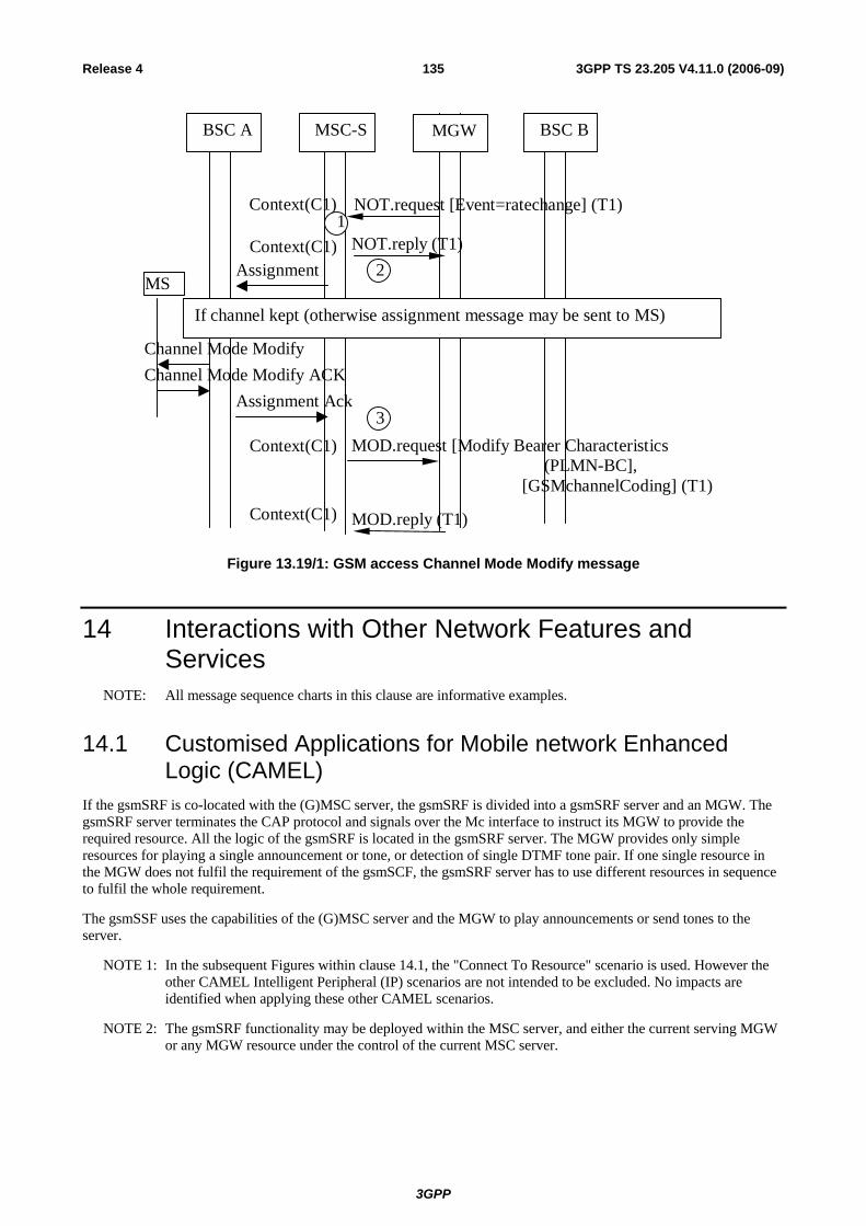
3GPP
3GPP TS 23.205 V4.11.0 (2006-09)135Release 4
BSC A
Context(C1) NOT.reply (T1)
Context(C1) NOT.request [Event=ratechange] (T1) 1
Context(C1) MOD.request [Modify Bearer Characteristics (PLMN-BC],
[GSMchannelCoding] (T1) Context(C1) MOD.reply (T1)
MSC-S MGW BSC B
Assignment
Assignment Ack
2
3
If channel kept (otherwise assignment message may be sent to MS)
Channel Mode Modify Channel Mode Modify ACK
MS
Figure 13.19/1: GSM access Channel Mode Modify message
14 Interactions with Other Network Features and Services
NOTE: All message sequence charts in this clause are informative examples.
14.1 Customised Applications for Mobile network Enhanced Logic (CAMEL)
If the gsmSRF is co-located with the (G)MSC server, the gsmSRF is divided into a gsmSRF server and an MGW. The gsmSRF server terminates the CAP protocol and signals over the Mc interface to instruct its MGW to provide the required resource. All the logic of the gsmSRF is located in the gsmSRF server. The MGW provides only simple resources for playing a single announcement or tone, or detection of single DTMF tone pair. If one single resource in the MGW does not fulfil the requirement of the gsmSCF, the gsmSRF server has to use different resources in sequence to fulfil the whole requirement.
The gsmSSF uses the capabilities of the (G)MSC server and the MGW to play announcements or send tones to the server.
NOTE 1: In the subsequent Figures within clause 14.1, the "Connect To Resource" scenario is used. However the other CAMEL Intelligent Peripheral (IP) scenarios are not intended to be excluded. No impacts are identified when applying these other CAMEL scenarios.
NOTE 2: The gsmSRF functionality may be deployed within the MSC server, and either the current serving MGW or any MGW resource under the control of the current MSC server.
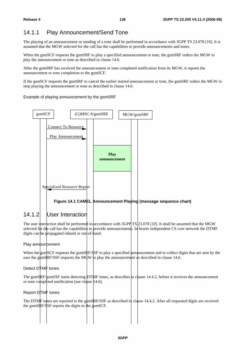
3GPP
3GPP TS 23.205 V4.11.0 (2006-09)136Release 4
14.1.1 Play Announcement/Send Tone The playing of an announcement or sending of a tone shall be performed in accordance with 3GPP TS 23.078 [10]. It is assumed that the MGW selected for the call has the capabilities to provide announcements and tones.
When the gsmSCF requests the gsmSRF to play a specified announcement or tone, the gsmSRF orders the MGW to play the announcement or tone as described in clause 14.6.
After the gsmSRF has received the announcement or tone completed notification from its MGW, it reports the announcement or tone completion to the gsmSCF.
If the gsmSCF requests the gsmSRF to cancel the earlier started announcement or tone, the gsmSRF orders the MGW to stop playing the announcement or tone as described in clause 14.6.
Example of playing announcement by the gsmSRF
Specialized Resource Report
Play Announcement
Connect To Resource
(G)MSC-S/gsmSRF MGW/gsmSRFgsmSCF
Playannouncement
Figure 14.1 CAMEL Announcement Playing (message sequence chart)
14.1.2 User Interaction The user interaction shall be performed in accordance with 3GPP TS 23.078 [10]. It shall be assumed that the MGW selected for the call has the capabilities to provide announcements. In bearer independent CS core network the DTMF digits can be propagated inband or out-of-band.
Play announcement
When the gsmSCF requests the gsmSRF/SSF to play a specified announcement and to collect digits that are sent by the user the gsmSRF/SSF requests the MGW to play the announcement as described in clause 14.6.
Detect DTMF tones
The gsmSRF/gsmSSF starts detecting DTMF tones, as describes in clause 14.4.2, before it receives the announcement or tone completed notification (see clause 14.6).
Report DTMF tones
The DTMF tones are reported to the gsmSRF/SSF as described in clause 14.4.2. After all requested digits are received the gsmSRF/SSF reports the digits to the gsmSCF.

3GPP
3GPP TS 23.205 V4.11.0 (2006-09)137Release 4
Cancel prompt and collect user information
If the gsmSCF requests the gsmSRF to cancel the prompt and collect user information procedure, which had been started earlier, the gsmSRF orders the MGW to stop playing the announcement or sending tone, if they are still in progress , using the Stop Announcement or the Stop Tone procedure. The gsmSRF shall also order the MGW to stop detecting DTMF tones using the Stop DTMF Detection procedure.
Prompt And Collect User Information Ack
Prompt And Collect User Information
Connect To Resource
gsmSRF/SSF MGWgsmSCF
Inband DTMFdetection and
Playannouncement
Out-of-band DTMF detection
Figure 14.2 CAMEL User Interaction (message sequence chart)
NOTE: Since gsmSRF don not know whether DTMF digits are provided inband or out-of-band the gsmSRF has to be able to collect DTMF tones both inband and out-of-band.
14.2 IST The handling of IST shall be performed in accordance with GSM TS 02.32 [19]. This clause describes the additional requirements for the Bearer Independent CS Core Network.
The clearing of calls due to IST is the same as for (G)MSC server initiated call clearing, refer to clause 7.3,(G)MSC server Initiated.
14.3 Operator Determined Barring (ODB) NOTE: The subsequent clauses in 14.3 describe the impacts of 'Barring of Outgoing Calls' and 'Barring of
Incoming Calls' on Bearer Independent CS CN. Other flavours of Operator Determined Barring may be supported by the Bearer Independent CS CN. However no impacts caused by these other flavours are identified.
14.3.1 Barring of Outgoing Calls If the mobile station attempts to connect to an address determined to be barred by the Operator Determined Barring service, the call shall be cleared as described in clause 7, Call Clearing.
Otherwise, the call is established as described in clause 6, Call Establishment.
14.3.2 Barring of Incoming Calls If the incoming call to the mobile station is determined to be barred by the Operator Determined Barring service, the call shall be barred. Otherwise the call shall be delivered as described in clause 6, Call Establishment.

3GPP
3GPP TS 23.205 V4.11.0 (2006-09)138Release 4
If the GMSC connects the call to a recorded announcement due to Operator Determined Barring, the GMSC server selects the MGW before providing the in-band information. It is possible that the MGW selection is based on an MGW-Id received from the preceding node.
The incoming side bearer establishment is handled in the GMSC server as described for the mobile terminating call using either forward or backward bearer establishment.
In-band information may be provided to the calling subscriber only when both of the following conditions are satisfied:
1. Either:
a. The incoming IAM indicated that the Continuity message will follow, and a Continuity message has been received, or
b. The incoming IAM did not indicate that the Continuity message will follow;
2. Notification indicating successful completion of the incoming side bearer set-up has been received from the MGW using the Bearer Established procedure.
The GMSC server provides the MGW with the announcement identification and requests the MGW to notify the announcement completion using the Play Announcement procedure as described in clause 4.6.
After the possible announcement has been completed the GMSC server initiates the call release as described in the clause 7, Call Clearing.
14.4 DTMF DTMF information can be transported either inband or out of band. In order to minimise the interworking between out of band and in band DTMF signalling, the general principle is to use the DTMF signalling method of the preceding node whenever possible. A node supporting OoB DTMF shall also be able to receive inband DTMF digits, but no DTMF digits shall be duplicated, i.e. any detected digit shall either be sent forward by inband or out-of-band, but never by both methods. Transitions between inband and out-of-band may occur due to changes to an ongoing call (Explicit Call Transfer for example) but digits shall not be sent both inband and OoB for the same link.
If out-of-band transcoder control is applied for a speech call, it shall be performed in accordance with 3GPP TS 23.153 [3]
14.4.1 DTMF Tone Generation
14.4.1.1 Inband DTMF Tone Generation
This option uses inband signalling to transport DTMF digits in the core network.
The DTMF tone generation shall be performed in accordance with 3GPP TS 23.108 [18]. The following paragraphs describe the additional requirements for the bearer independent CS core network.
Start DTMF
When the MSC server receives the Start DTMF message from the UE, it uses the Send DTMF procedure to request the MGW to modify the bearer termination to play a tone for the pressed digit. The result of the tone sending by the bearer termination will be received by the MSC server and sent to the UE (bullet 1 in figure 14.3).
Stop DTMF
When the MSC server receives the Stop DTMF message from the UE, it uses the Stop DTMF procedure to request the MGW to modify the bearer termination to stop digit playing. When the response is received from the MGW, the MSC server will acknowledge the Stop DTMF (bullet 2 in figure 14.3).
The MGW shall check the minimum duration and minimum interval in accordance with the DTMF timing defined in TS 23.014 [28].

3GPP
3GPP TS 23.205 V4.11.0 (2006-09)139Release 4
Example
Figure 14.3 shows an example where out-of-band signalling of DTMF information is not supported by the call control protocol. When the UE sends Start DTMF and Stop DTMF messages , the MSC server uses resources in the MGW to generate tones by modifying the bearer termination.
Stop DTMF
Send DTMF
Context (Cx) MOD.reply (Tx)
Context (Cx) MOD.request)
STOP DTMF ACK
STOP DTMF
Context (Cx) MOD.reply (Tx)
Context (Cx) MOD.request (Tx)
START DTMF ACK
START DTMF
UE RNC MSC-S MGW
1
2
Figure 14.3 Inband DTMF generation (message sequence chart)
14.4.1.2 Out-of-Band DTMF Tone Generation
This option uses out-of-band network signalling to transport DTMF digits in the core network, where the information is sent on a call control layer.
The DTMF Tone Generation shall be performed in accordance with 3GPP TS 23.108 [18]. The following paragraphs describe the additional requirements for the bearer independent CS core network.
Start DTMF
When the MSC server receives a Start DTMF message from the UE, it indicates digit playing using out-of-band signalling. The corresponding result received from the preceding/succeeding node will be sent to the UE (bullet 1 in figure 14.4).
Stop DTMF
When the MSC server receives a Stop DTMF message from the UE, it indicates stop digit playing using out-of-band signalling. The succeeding node will indicate that digit playing is stopped. The MSC server will send the result back to the UE (bullet 2 in figure 14.4).
Example
Figure 14.4 shows the message sequence example for the out-of-band DTMF during a call. When the MSC server receives the Start DTMF and Stop DTMF messages from the UE, it shall send the information using signalling on call control layer. The MSC server will not use any dedicated resources of the MGW.
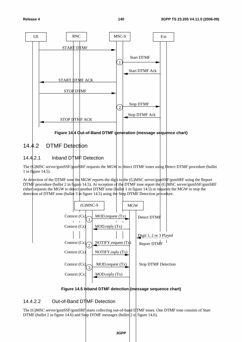
3GPP
3GPP TS 23.205 V4.11.0 (2006-09)140Release 4
Start DTMF Ack
Start DTMF
STOP DTMF ACK
STOP DTMF
START DTMF ACK
START DTMF
UE RNC MSC-S Ext
Stop DTMF
Stop DTMF Ack
1
2
Figure 14.4 Out-of-Band DTMF generation (message sequence chart)
14.4.2 DTMF Detection
14.4.2.1 Inband DTMF Detection
The (G)MSC server/gsmSSF/gsmSRF requests the MGW to detect DTMF tones using Detect DTMF procedure (bullet 1 in figure 14.5).
At detection of the DTMF tone the MGW reports the digit to the (G)MSC server/gsmSSF/gsmSRF using the Report DTMF procedure (bullet 2 in figure 14.5). At reception of the DTMF tone report the (G)MSC server/gsmSSF/gsmSRF either requests the MGW to detect another DTMF tone (bullet 1 in figure 14.5) or requests the MGW to stop the detection of DTMF tone (bullet 3 in figure 14.5) using the Stop DTMF Detection procedure.
Context (Cx) NOTIFY.reply (Tx)
Context (Cx) NOTIFY.request (Tx)
Digit 1, 2 or 3 Played
Context (Cx) MOD.reply (Tx)
Context (Cx) MOD.request (Tx)
Context (Cx) MOD.reply (Tx)
Context (Cx) MOD.request (Tx)
(G)MSC-S MGW
1
3
Detect DTMF
Report DTMF
Stop DTMF Detection
2
Figure 14.5 Inband DTMF detection (message sequence chart)
14.4.2.2 Out-of-Band DTMF Detection
The (G)MSC server/gsmSSF/gsmSRF starts collecting out-of-band DTMF tones. One DTMF tone consists of Start DTMF (bullet 1 in figure 14.6) and Stop DTMF messages (bullet 2 in figure 14.6).

3GPP
3GPP TS 23.205 V4.11.0 (2006-09)141Release 4
Start DTMF
Start DTMF Ack
Stop DTMF
Stop DTMF Ack
(G)MSC-S MGW
1
2
Figure 14.6 Out-of-Band DTMF detection (message sequence chart)
14.5 OR The procedures specified in 3GPP TS 23.079 [11] for the Optimal Routeing network service shall be followed. The following paragraphs describe the additional requirements for the bearer independent CS core network.
14.5.1 Optimal routeing for basic mobile-to-mobile calls The optimally routed call from one mobile subscriber to another mobile subscriber is established as a normal basic call.
14.5.2 Optimal routeing for conditional call forwarding; Early call forwarding For early call forwarding the same procedures as described for CFU and CFNRc (rerouting by HLR) shall apply.
14.5.3 Optimal routeing for conditional call forwarding; Late call forwarding
14.5.3.1 MSC server
Resume Call Handling and clearing of connection to GMSC server
When the MSC server determines that the call should be forwarded because the called mobile subscriber is busy (NDUB, UDUB), not reachable or has not replied to the call before the no-reply timer has expired, the MSC server sends a request to resume call handling to the GMSC server.
If the GMSC server determines that the call can be forwarded to the forwarded-to destination it sends a Release message to the MSC server. If no bearer has been established yet the MSC server handles the release only on call control level. If the bearer had been established, the MSC server handles the network side bearer release as described in the clause for the call clearing.
IU release
When the MSC server determines that the call should be forwarded because the called mobile subscriber is busy (UDUB) or it has not replied to the call before the no-reply call timer has expired, the MSC server shall release the call and bearer connection to the served mobile subscriber as described in the clause for call clearing.
14.5.3.2 GMSC server
Resume Call Handling and Clearing of Connection to visited MSC server
If the GMSC server determines that the call can be forwarded to the forwarded-to destination it sends a Release message to the MSC server and handles the outgoing side bearer release as described in the clause for call clearing, if the bearer had already been established.

3GPP
3GPP TS 23.205 V4.11.0 (2006-09)142Release 4
MGW selection
The GMSC server shall select an MGW for the bearer connection as described for the CFU and CFNRc (in HLR) supplementary services, if not already selected by the mobile terminating call procedures.
Incoming side bearer establishment
The bearer establishment towards the preceding MGW is handled in the GMSC server as described for the mobile terminating call, if not already established by the mobile terminating call procedures.
Notification to the Calling Subscriber
The GMSC server sends the possible notification towards the calling subscriber according to the procedures described for the CFU and CFNRc (in HLR) supplementary services.
Establishment of call and bearer towards the forwarded-to subscriber
The GMSC server establishes the call and bearer towards the forwarded-to subscriber according to the procedures described for the CFU and CFNRc (in HLR) supplementary services.
Example
Figure 14.7 shows the network model for optimal routeing when no bearer has been established before the invocation of late call forwarding. The 'squared' line represents the call control signalling. The 'dotted' line represents the bearer control signalling and the bearer. The GMSC server seizes one context with two bearer terminations in the MGW. The bearer termination TA is used for the bearer towards the preceding MGW (calling subscriber) and the bearer termination TC is used for the bearer towards the succeeding MGW (forwarded-to subscriber).
GMSC-S
Before CFB (NDUB), CFNRc:
MGW
GMSC-S
CTX1Tx TC
After CFB (NDUB), CFNRc:
MSC-S
Figure 14.7: Optimal routeing; late call forwarding (CFB (NDUB), CFNRc) (Network model)
Figure 14.8 shows the message sequence example for the optimal routeing with late call forwarding without any notification to the calling party. In the example below no bearer has been established for the connection when the MSC server sends the Resume Call Handling request to the GMSC server. After the call towards the visited MSC server has been released the GMSC server establishes the call and the bearer as described for Call Forwarding Unconditional.
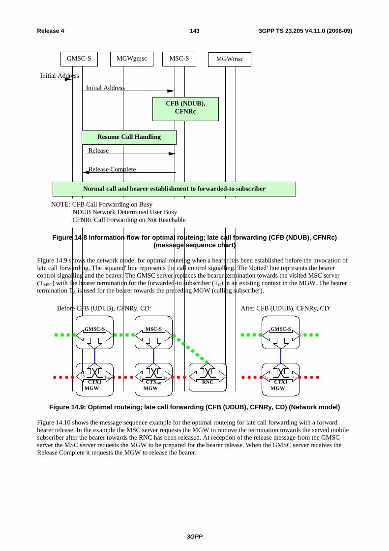
3GPP
3GPP TS 23.205 V4.11.0 (2006-09)143Release 4
Release
Initial Address
MSC-S MGWmscGMSC-S MGWgmsc
Initial Address
CFB (NDUB),CFNRc
Resume Call Handling
Normal call and bearer establishment to forwarded-to subscriber
Release Complete
NOTE: CFB Call Forwarding on Busy NDUB Network Determined User Busy CFNRc Call Forwarding on Not Reachable
Figure 14.8 Information flow for optimal routeing; late call forwarding (CFB (NDUB), CFNRc) (message sequence chart)
Figure 14.9 shows the network model for optimal routeing when a bearer has been established before the invocation of late call forwarding. The 'squared' line represents the call control signalling. The 'dotted' line represents the bearer control signalling and the bearer. The GMSC server replaces the bearer termination towards the visited MSC server (TMSC) with the bearer termination for the forwarded-to subscriber (TC) in an existing context in the MGW. The bearer termination TA is used for the bearer towards the preceding MGW (calling subscriber).
MGW
MSC-S
CTXAB
TA TB
Before CFB (UDUB), CFNRy, CD:
MGW
GMSC-S
CTX1TX TC
After CFB (UDUB), CFNRy, CD:
RNC MGW
GMSC-S
CTX1TX TMSC
Figure 14.9: Optimal routeing; late call forwarding (CFB (UDUB), CFNRy, CD) (Network model)
Figure 14.10 shows the message sequence example for the optimal routeing for late call forwarding with a forward bearer release. In the example the MSC server requests the MGW to remove the termination towards the served mobile subscriber after the bearer towards the RNC has been released. At reception of the release message from the GMSC server the MSC server requests the MGW to be prepared for the bearer release. When the GMSC server receives the Release Complete it requests the MGW to release the bearer.
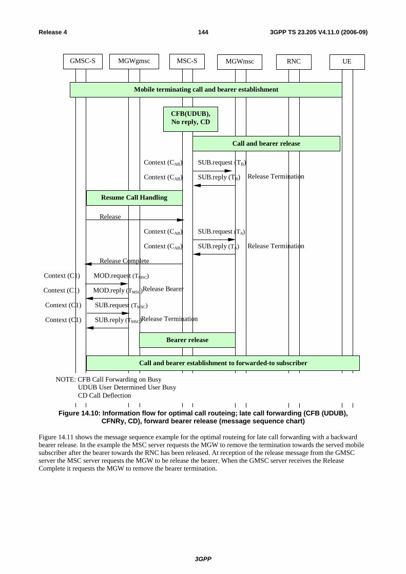
3GPP
3GPP TS 23.205 V4.11.0 (2006-09)144Release 4
Context (CAB) SUB.request (TA)
UERNCMSC-S MGWmscGMSC-S MGWgmsc
Mobile terminating call and bearer establishment
CFB(UDUB),No reply, CD
Release
Resume Call Handling
Call and bearer establishment to forwarded-to subscriber
Context (CAB) SUB.reply (TB)
Context (CAB) SUB.request (TB)
Call and bearer release
Context (CAB) SUB.reply (TA)
Release Complete
Context (C1) SUB.request (TMSC)
Context (C1) SUB.reply (TMSC)
Bearer release
NOTE: CFB Call Forwarding on Busy UDUB User Determined User Busy CD Call Deflection
Release Termination
Release Termination
Context (C1) MOD.request (TMSC)
Context (C1) MOD.reply (TMSC)Release Bearer
Release Termination
Figure 14.10: Information flow for optimal call routeing; late call forwarding (CFB (UDUB), CFNRy, CD), forward bearer release (message sequence chart)
Figure 14.11 shows the message sequence example for the optimal routeing for late call forwarding with a backward bearer release. In the example the MSC server requests the MGW to remove the termination towards the served mobile subscriber after the bearer towards the RNC has been released. At reception of the release message from the GMSC server the MSC server requests the MGW to be release the bearer. When the GMSC server receives the Release Complete it requests the MGW to remove the bearer termination.

3GPP
3GPP TS 23.205 V4.11.0 (2006-09)145Release 4
Context (CAB) SUB.request (TA)
UERNCMSC-S MGWmscGMSC-S MGWgmsc
Mobile terminating call and bearer establishment
CFB(UDUB),No reply, CD
Release
Resume Call Handling
Call and bearer establishment to forwarded-to subscriber
Context (CAB) SUB.reply (TB)
Context (CAB) SUB.request (TB)
Call and bearer release
Context (CAB) SUB.reply (TA)
Release Complete
Context (C1) SUB.request (TMSC)
Context (C1) SUB.reply (TMSC)
Bearer release
NOTE: CFB Call Forwarding on Busy UDUB User Determined User Busy CD Call Deflection
Release Termination
Release Termination
Context (CAB) MOD.request (TA)
Context (CAB) MOD.reply (TA) Release Bearer
Release Termination
Figure 14.11: Optimal call routeing; late call forwarding (CFB (UDUB), CFNRy, CD), backward bearer release (message sequence chart)
14.6 Providing tones or announcements It shall be assumed that the MGW selected for the call has the capabilities to provide announcements/tones.

3GPP
3GPP TS 23.205 V4.11.0 (2006-09)146Release 4
Preconditions when providing in-band information to the calling subscriber
For a mobile terminating/forwarded call, announcements/tones may be provided to the calling subscriber only when both of the following conditions are satisfied:
1. Either:
a. The incoming IAM indicated that the Continuity message will follow, and a Continuity message has been received, or
b. The incoming IAM did not indicate that the Continuity message will follow;
2. Notification indicating successful completion of the incoming side bearer set-up has been received from the MGW using the Bearer Established procedure.
If mobile originating call, the traffic channel assignment shall be completed before providing the in-band information to the calling subscriber.
Request to play an announcement/tone
The (G)MSC server/gsmSSF/gsmSRF provides the MGW with the announcement/tone identification and optionally requests the MGW to notify the announcement/tone completion using the Play Announcement or Send Tone procedure (bullet 1 in figure 14.13).
Stopping an announcement/tone
The (G)MSC server/gsmSSF/gsmSRF can order the MGW to stop the current announcement/tone using the Stop Announcement or Stop Tone procedure (bullet 2 in figure 14.13).
Announcement/tone completed
If notification of the announcement/tone completion was requested in the Play Announcement or Send Tone procedure, the MGW notifies the (G)MSC server/gsmSSF/gsmSRF when the announcement/tone has been completed using the Announcement Completed or Tone Completed procedure (bullet 3 in figure 14.13).
Example
Figure 14.12 shows the network model for providing in-band information to the calling subscriber. The 'squared' line represents the call control signalling. The 'dotted' line represents the bearer control signalling and the bearer. The bearer termination Tx is used for the bearer towards the preceding MGW (calling subscriber).
MGW
(G)MSC-S
CTXxTx
Figure 14.12: Proving in-band information (Network model)
Figure 14.13 shows the message sequence example for providing the calling party with an announcement/tone. In the example the (G)MSC server requests the MGW to play an announcement/tone and to notify the announcement/tone completion. The (G)MSC server may stop the announcement while the current announcement/tone is ongoing.
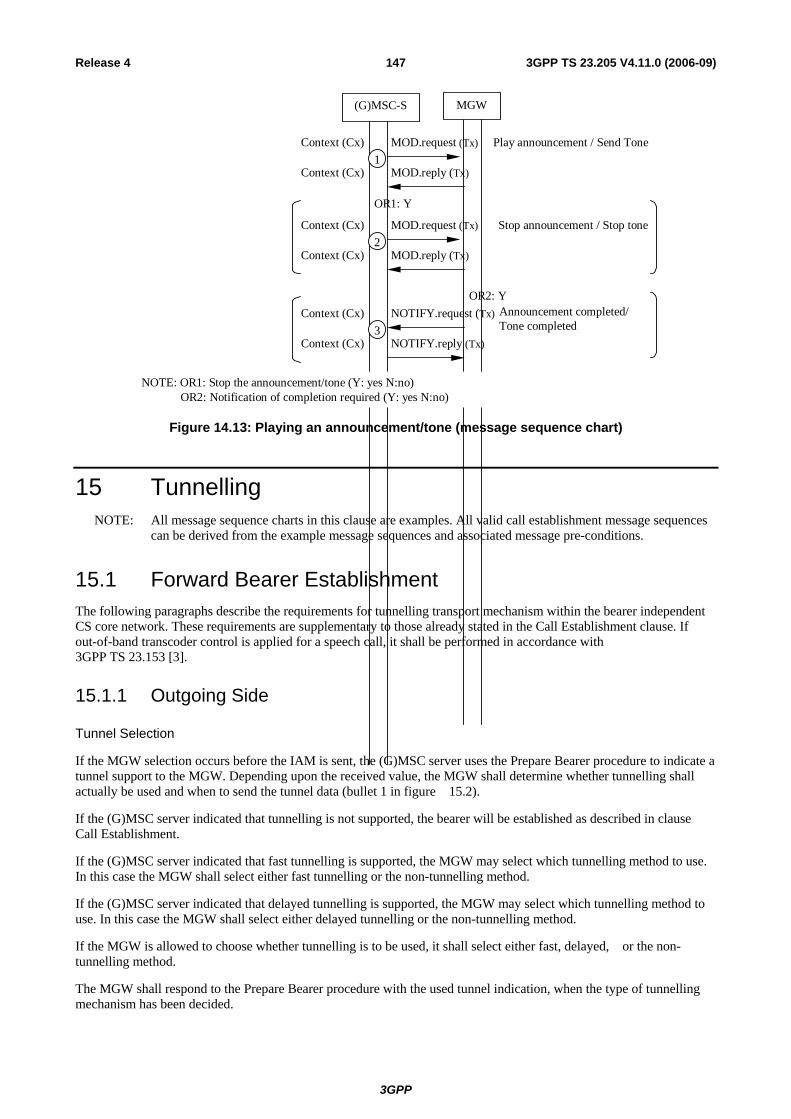
3GPP
3GPP TS 23.205 V4.11.0 (2006-09)147Release 4
(G)MSC-S MGW
Context (Cx) MOD.request (Tx)
Context (Cx) MOD.reply (Tx)
Context (Cx) NOTIFY.request (Tx)
Context (Cx) NOTIFY.reply (Tx)
1
3
Play announcement / Send Tone
Announcement completed/Tone completed
Context (Cx) MOD.request (Tx)
Context (Cx) MOD.reply (Tx)2
Stop announcement / Stop tone
OR1: Y
NOTE: OR1: Stop the announcement/tone (Y: yes N:no) OR2: Notification of completion required (Y: yes N:no)
OR2: Y
Figure 14.13: Playing an announcement/tone (message sequence chart)
15 Tunnelling NOTE: All message sequence charts in this clause are examples. All valid call establishment message sequences
can be derived from the example message sequences and associated message pre-conditions.
15.1 Forward Bearer Establishment The following paragraphs describe the requirements for tunnelling transport mechanism within the bearer independent CS core network. These requirements are supplementary to those already stated in the Call Establishment clause. If out-of-band transcoder control is applied for a speech call, it shall be performed in accordance with 3GPP TS 23.153 [3].
15.1.1 Outgoing Side
Tunnel Selection
If the MGW selection occurs before the IAM is sent, the (G)MSC server uses the Prepare Bearer procedure to indicate a tunnel support to the MGW. Depending upon the received value, the MGW shall determine whether tunnelling shall actually be used and when to send the tunnel data (bullet 1 in figure 15.2).
If the (G)MSC server indicated that tunnelling is not supported, the bearer will be established as described in clause Call Establishment.
If the (G)MSC server indicated that fast tunnelling is supported, the MGW may select which tunnelling method to use. In this case the MGW shall select either fast tunnelling or the non-tunnelling method.
If the (G)MSC server indicated that delayed tunnelling is supported, the MGW may select which tunnelling method to use. In this case the MGW shall select either delayed tunnelling or the non-tunnelling method.
If the MGW is allowed to choose whether tunnelling is to be used, it shall select either fast, delayed, or the non-tunnelling method.
The MGW shall respond to the Prepare Bearer procedure with the used tunnel indication, when the type of tunnelling mechanism has been decided.

3GPP
3GPP TS 23.205 V4.11.0 (2006-09)148Release 4
NOTE: For a given bearer type, other specifications may describe the mechanism to be used to transport bearer control information. An MGW is only required to comply with that specification.
Initial addressing
If the MGW selection has occurred, the MGW shall respond to the Prepare Bearer procedure indicating whether tunnelling is allowed and what type of tunnelling is used – fast or delayed forward. The (G)MSC server provides a tunnel indicator to the succeeding node in the IAM to indicate that tunnelling is to be used. For fast tunnelling, the (G)MSC server waits for the MGW to use the Tunnel Information Up procedure to provide the tunnel data before the IAM is sent.
If the MGW indicates that tunnelling is not to be used, then tunnel indicator is not included in the Initial Address message and the bearer will be established as described in clause Call Establishment.
If the MGW has not been selected yet, then the (G)MSC server decides whether delayed tunnelling is supported or not. If the delayed tunnelling is supported the tunnel indicator is included to the Initial Address message to indicate that. Otherwise the tunnel indicator is not included to the Initial Address message and the bearer will be established as described in clause Call Establishment.
Fast forward tunnelling
The tunnel data is transferred in the IAM and the subsequent Tunnel Information message(s).
Before the IAM is sent, the (G)MSC server waits for the MGW to use the Tunnel Information Up procedure to supply the tunnel data. The (G)MSC server sends the received tunnel data to the succeeding node in the IAM (bullet 2 in example sequence 15.2).
When the (G)MSC server receives a Tunnel Information message from the succeeding node the (G)MSC server uses the Tunnel Information Down procedure to supply the MGW with the received tunnel data (bullet 5 in example sequence 15.2).
Delayed forward tunnelling
The tunnel data is transferred in the Tunnel Information messages following the Bearer Information message.
If tunnel indicator was included in the IAM indicating that delayed tunnelling is supported, the succeeding node may include the tunnel indicator to the Bearer Information message. If the tunnel indicator is received the (G)MSC server indicates the delayed tunnel support in the Establish Bearer procedure.
When the MGW sends the Tunnel Information Up procedure, the (G)MSC server sends the received tunnel data in the Tunnel Information message to the succeeding node.
When the (G)MSC server receives a Tunnel Information message from the succeeding node, the (G)MSC server uses the Tunnel Information Down procedure to send the received tunnel data to the MGW.
Bearer control signalling transfer
The tunnelling of the bearer control signalling is transported transparently through the (G)MSC server during the call establishment and at any other time until Release is sent or received.
15.1.2 Incoming Side
Initial addressing
The (G)MSC server receives the possible tunnel indicator and the tunnel data in IAM. Based on received information it provides the tunnel support indication and the tunnel data to the MGW.

3GPP
3GPP TS 23.205 V4.11.0 (2006-09)149Release 4
Tunnel Selection
If the tunnel indicator was received in the IAM, the (G)MSC server uses the received tunnel indicator to indicate the support of tunnel to the MGW. If the tunnel indicator is received in the IAM without tunnel data, the (G)MSC server checks the value of the tunnel indicator. If the tunnel indicator indicates that tunnel mechanism is to be used then delayed tunnelling is indicated to the MGW. If the tunnel indicator indicates that tunnel mechanism is supported the (G)MSC server decides whether the delayed tunnel is supported or non tunnelling mechanism is used. If both tunnel indicator and tunnel data are received in the IAM, fast tunnelling is indicated to the MGW.
If no tunnel indicator was received in the IAM, then the preceding node has indicated that non-tunnelling mechanism is to be used.
The (G)MSC server uses the Prepare Bearer procedure to supply the tunnel support indication to the MGW.
The MGW decides based on the received tunnel support indication from the (G)MSC server whether to use delayed tunnelling or not. In the response the MGW provides the used tunnel indication to the (G)MSC server.
Fast forward tunnelling
The tunnel data is transferred in the IAM and the subsequent Tunnel Information message(s).
The (G)MSC server sends the tunnel data received in the IAM to the MGW using the Tunnel Information Down procedure (bullet 3 in example sequence 15.2).
When the MGW sends the Tunnel Information Up procedure, the (G)MSC server sends the received tunnel data in the Tunnel Information message to the preceding node (bullet 4 in example sequence 15.2).
Delayed forward tunnelling
The tunnel data is transferred in the Tunnel Information messages following the Bearer Information message.
If tunnel indicator was received in the IAM indicating that delayed tunnel is supported and delayed tunnelling was indicated by the MGW, the (G)MSC server shall include the tunnel indicator to the Bearer Information message which is sent to the preceding node.
When the (G)MSC server receives a Tunnel Information message from the preceding node, the (G)MSC server uses the Tunnel Information Down procedure to send the received tunnel data to the MGW.
When the MGW sends the Tunnel Information Up procedure, the (G)MSC server sends the received tunnel data in the Tunnel Information message to the preceding node.
Bearer control signalling transfer.
The tunnelling of bearer control signalling is transported transparently during the call establishment and at any other time until Release is sent or received.
Example
Figure 15.1 shows the network model for the forward tunnelling transport mechanism. The 'squared' line represents the call control signalling. The 'dotted' line represents the bearer control signalling. The (G)MSCa seizes one context with two bearer terminations in MGWa. The bearer termination T1 is used for the bearer towards the incoming side of (G)MSCa and the bearer termination T2 is used for the tunnelling towards the succeeding MGW. The (G)MSCb seizes one context with two bearer terminations in MGWb. The bearer termination T3 is used for the bearer towards the outgoing side of (G)MSCb and the bearer termination T4 is used for the tunnelling towards the preceding MGW.
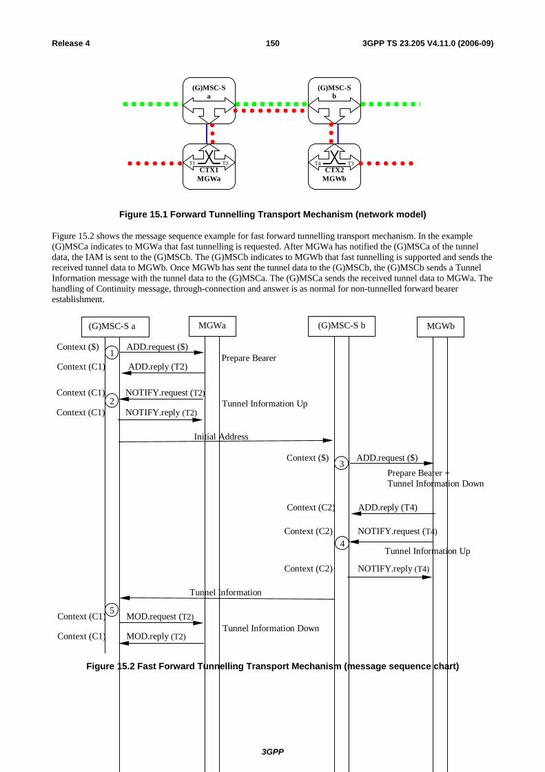
3GPP
3GPP TS 23.205 V4.11.0 (2006-09)150Release 4
MGWbMGWa
(G)MSC-Sa
(G)MSC-Sb
CTX1T1 T2
CTX2T4 T3
Figure 15.1 Forward Tunnelling Transport Mechanism (network model)
Figure 15.2 shows the message sequence example for fast forward tunnelling transport mechanism. In the example (G)MSCa indicates to MGWa that fast tunnelling is requested. After MGWa has notified the (G)MSCa of the tunnel data, the IAM is sent to the (G)MSCb. The (G)MSCb indicates to MGWb that fast tunnelling is supported and sends the received tunnel data to MGWb. Once MGWb has sent the tunnel data to the (G)MSCb, the (G)MSCb sends a Tunnel Information message with the tunnel data to the (G)MSCa. The (G)MSCa sends the received tunnel data to MGWa. The handling of Continuity message, through-connection and answer is as normal for non-tunnelled forward bearer establishment.
Tunnel Information Down
Prepare Bearer +Tunnel Information Down
Context (C2) ADD.reply (T4)
Context ($) ADD.request ($)
Tunnel Information Up
Tunnel Information Up
Prepare BearerContext (C1) ADD.reply (T2)
Context ($) ADD.request ($)
Tunnel Information
Initial Address
Context (C1) NOTIFY.request (T2)
Context (C1) NOTIFY.reply (T2)2
Context (C2) NOTIFY.request (T4)
Context (C2) NOTIFY.reply (T4)
(G)MSC-S a MGWa (G)MSC-S b MGWb
4
Context (C1) MOD.request (T2)
Context (C1) MOD.reply (T2)
1
3
5
Figure 15.2 Fast Forward Tunnelling Transport Mechanism (message sequence chart)

3GPP
3GPP TS 23.205 V4.11.0 (2006-09)151Release 4
15.2 Backward Bearer Establishment The following paragraphs describe the additional requirements for tunnelling transport mechanism within the bearer independent CS core network. If out-of-band transcoder control is applied for a speech call, it shall be performed in accordance with 3GPP TS 23.153[3].
15.2.1 Outgoing Side
Tunnel Selection
The (G)MSC server uses the Prepare Bearer procedure to indicate a tunnel support to the MGW. Depending upon the received value, the MGW shall determine whether tunnelling shall actually be used and when to send the tunnel data (bullet 1 in example sequence 15.4).
If the (G)MSC server indicated that tunnelling will be not supported, the bearer is established as described in clause Call Establishment.
If the (G)MSC server indicated that fast tunnelling is supported, the MGW may select which tunnelling method it can use. In this case the (G)MSC may select either fast tunnelling or the non-tunnelling method.
If the (G)MSC server indicated that delayed tunnelling is supported, the MGW may select which tunnelling method it can use. In this case the (G)MSC server may select either delayed tunnelling the non-tunnelling method.
If the MGW is allowed to choose whether tunnelling is to be used, it shall select either fast, delayed or the non-tunnelling method.
After MGW has decided which tunnelling mechanism to use , it responds to the Prepare Bearer procedure with the used tunnel indication.
Initial addressing
The MGW shall respond to the Prepare Bearer procedure to indicate whether tunnelling is allowed and what type of tunnelling is used – fast or delayed forward. The (G)MSC server provides a tunnel indicator to the succeeding node in the IAM. For fast tunnelling, the (G)MSC server waits for the MGW to use the Tunnel Information Up procedure to provide the tunnel data before the IAM is sent.
If the MGW indicates that tunnelling is not to be used, the bearer will be established as described in clause Call Establishment.
Fast forward tunnelling
The tunnel data is transferred in the IAM and the subsequent Tunnel Information message(s).
Before the IAM is sent, the (G)MSC server waits for the MGW to use the Tunnel Information Up procedure to supply the tunnel data. The (G)MSC server sends the received tunnel data to the succeeding node in the IAM.
When the (G)MSC server receives a Tunnel Information message from the succeeding node the (G)MSC server uses the Tunnel Information Down procedure to supply the MGW with the received tunnel data.
Delayed backward tunnelling
The tunnel data is transferred in the Tunnel Information messages following the IAM.
When the (G)MSC server receives a Tunnel Information message from the succeeding node the (G)MSC server uses the Tunnel Information Down procedure to supply the MGW with the received tunnel data (bullet 4 in example sequence 15.4).
When the MGW sends the Tunnel Information Up procedure, the (G)MSC server sends the received tunnel data in the Tunnel Information message to the succeeding node (bullet 5 in example sequence 15.4).

3GPP
3GPP TS 23.205 V4.11.0 (2006-09)152Release 4
Bearer control signalling transfer
The tunnelling of bearer control signalling is transported transparently through the (G)MSC server during the call establishment and at any other time until Release is sent or received.
15.2.2 Incoming Side
Initial addressing
The (G)MSC server receives the possible tunnel indicator and the tunnel data in the IAM. Based on received information it provides the tunnel support indication and the tunnel data to the MGW.
Tunnel Selection
If the tunnel indicator was received in the IAM, the (G)MSC server uses the received tunnel indicator to indicate the support of tunnel to the MGW. If the tunnel indicator is received in the IAM without tunnel data, delayed tunnelling is indicated to the MGW. If tunnel indicator and tunnel data are received in the IAM, fast tunnelling is indicated to the MGW.
The (G)MSC server uses the Establish Bearer procedure to supply the tunnel support indication to the MGW (bullet 2 in example sequence 15.4).
Fast forward tunnelling
The tunnel data is transferred in the IAM and the subsequent Tunnel Information message(s).
The (G)MSC server sends the tunnel data received in the IAM to the MGW using the Tunnel Information Down procedure.
When the MGW sends the Tunnel Information Up procedure, the (G)MSC server sends the received tunnel data in the Tunnel Information message to the preceding node.
Delayed backward tunnelling
When the MGW sends the Tunnel Information Up procedure, the (G)MSC server sends the received tunnel data in the Tunnel Information message to the preceding node (bullet 3 in example sequence 15.4).
When the (G)MSC server receives a Tunnel Information message from the preceding node, the (G)MSC server uses the Tunnel Information Down procedure to send the received tunnel data to the MGW (bullet 6 in example sequence 15.4).
Bearer control signalling transfer
The tunnelling of bearer control signalling is transported transparently through the (G)MSC server during the call establishment and at any other time until Release is sent or received.
Example
Figure 15.3 shows the network model for the backward delayed tunnelling transport mechanism. The 'squared' line represents the call control signalling. The 'dotted' line represents the bearer control signalling. The (G)MSCa seizes one context with two bearer terminations in MGWa. The bearer termination T1 is used for the bearer towards the incoming side of (G)MSCa and the bearer termination T2 is used for the tunnelling towards the succeeding MGW. The (G)MSCb seizes one context with two bearer terminations in MGWb. The bearer termination T3 is used for the bearer towards the outgoing side of (G)MSCb and the bearer termination T4 is used for the tunnelling towards the preceding MGW.
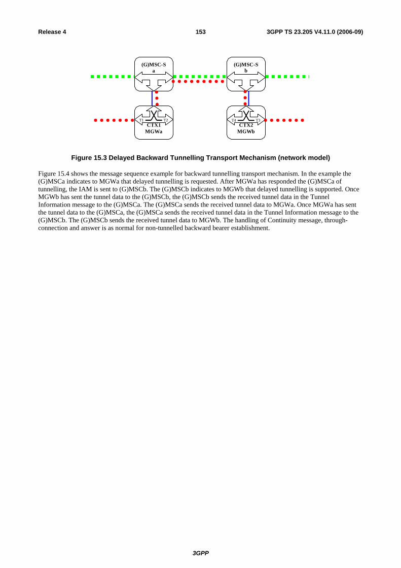
3GPP
3GPP TS 23.205 V4.11.0 (2006-09)153Release 4
MGWbMGWa
(G)MSC-Sa
(G)MSC-Sb
CTX1T1 T2
CTX2T4 T3
Figure 15.3 Delayed Backward Tunnelling Transport Mechanism (network model)
Figure 15.4 shows the message sequence example for backward tunnelling transport mechanism. In the example the (G)MSCa indicates to MGWa that delayed tunnelling is requested. After MGWa has responded the (G)MSCa of tunnelling, the IAM is sent to (G)MSCb. The (G)MSCb indicates to MGWb that delayed tunnelling is supported. Once MGWb has sent the tunnel data to the (G)MSCb, the (G)MSCb sends the received tunnel data in the Tunnel Information message to the (G)MSCa. The (G)MSCa sends the received tunnel data to MGWa. Once MGWa has sent the tunnel data to the (G)MSCa, the (G)MSCa sends the received tunnel data in the Tunnel Information message to the (G)MSCb. The (G)MSCb sends the received tunnel data to MGWb. The handling of Continuity message, through-connection and answer is as normal for non-tunnelled backward bearer establishment.
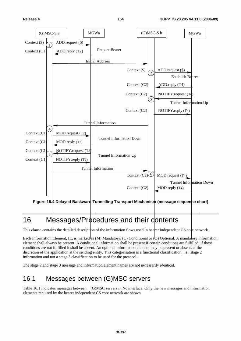
3GPP
3GPP TS 23.205 V4.11.0 (2006-09)154Release 4
Tunnel Information Down
Tunnel Information DownContext (C1) MOD.request (T2)
Context (C1) MOD.reply (T2)
Tunnel Information
Tunnel Information UpContext (C1) NOTIFY.request (T2)
Context (C1) NOTIFY.reply (T2)5
Establish Bearer
Context (C2) ADD.reply (T4)
Context ($) ADD.request ($)
Tunnel Information Up
Prepare BearerContext (C1) ADD.reply (T2)
Context ($) ADD.request ($)
Tunnel Information
Initial Address
Context (C2) NOTIFY.request (T4)
Context (C2) NOTIFY.reply (T4)
(G)MSC-S a MGWa (G)MSC-S b MGWa
3
1
Context (C2) MOD.request (T4)
Context (C2) MOD.reply (T4)
2
4
6
Figure 15.4 Delayed Backward Tunnelling Transport Mechanism (message sequence chart)
16 Messages/Procedures and their contents This clause contains the detailed description of the information flows used in bearer independent CS core network.
Each Information Element, IE, is marked as (M) Mandatory, (C) Conditional or (O) Optional. A mandatory information element shall always be present. A conditional information shall be present if certain conditions are fulfilled; if those conditions are not fulfilled it shall be absent. An optional information element may be present or absent, at the discretion of the application at the sending entity. This categorisation is a functional classification, i.e., stage 2 information and not a stage 3 classification to be used for the protocol.
The stage 2 and stage 3 message and information element names are not necessarily identical.
16.1 Messages between (G)MSC servers Table 16.1 indicates messages between (G)MSC servers in Nc interface. Only the new messages and information elements required by the bearer independent CS core network are shown.

3GPP
3GPP TS 23.205 V4.11.0 (2006-09)155Release 4
Table 16.1: Messages between (G)MSC servers
Message Message direction
Information element name
Information element required
Information element description
Bearer Establishment Direction
M This information element indicates that the direction of bearer establishment.
Bearer Address C This information element indicates the bearer address of the MGW used by the preceding node. This information element is included when backward bearer establishment using bearer control protocol is used. Otherwise the information element is optional.
Binding Reference C This information element indicates the bearer identifier in the MGW used by the preceding node. This information element is included when backward bearer establishment using bearer control protocol is used. Otherwise the information element is optional.
MGW-id O This information element indicates the MGW selected by the preceding node.
Bearer Characteristics
M This information element indicates the characteristics of the bearer.
Tunnel Indicator O This information element indicates either that tunnelling is to be used or tunnelling is supported.
Initial Address Forward
Tunnel data O This information element contains the tunnel data that is provided between MGWs.
Bearer Information
Backward Bearer Address C This information element indicates the bearer address of the MGW used by the succeeding node. This information element is included when bearer is established using bearer control protocol. Otherwise the information element is optional.
Binding Reference C This information element indicates the bearer identifier in the MGW used by the succeeding node. This information element is included when bearer is established using bearer control protocol. Otherwise the information element is optional.
MGW-id O This information element indicates the MGW selected by the succeeding node.
Tunnel Indicator O This information element indicates that tunnelling is used.
Tunnel Information
Both Tunnel Indicator M This information element indicates that the message contains tunnelling information.
Tunnel data M This information element contains the tunnel data that is provided between MGWs.
Start DTMF Both Start DTMF indicator M This information element indicates that the message is used for Start DTMF.
Digit M This information element indicates the digit for DTMF tone generation.
Start DTMF Ack Both Start DTMF Ack indicator
M This information element indicates that the message is used for Start DTMF Ack.
Stop DTMF Both Stop DTMF indicator M This information element indicates that the message is used for Stop DTMF.
Stop DTMF Ack Both Stop DTMF Ack indicator
M This information element indicates that the message is used for Stop DTMF Ack.

3GPP
3GPP TS 23.205 V4.11.0 (2006-09)156Release 4
16.2 Procedures between (G)MSC server and MGW The clauses below indicate the procedures used between (G)MSC server and MGW in Mc interface. The procedures are logical, i.e. message identifiers are not part of the protocol. Several logical procedures can be combined into one H.248 command in order to perform required transactions. If several logical procedures are combined, only one context/context request and only one bearer termination/bearer termination request is sent in the H.248 command. Exemption is the Change Flow Direction procedure, where the two bearer terminations are related to a change of the context and not to a command of the bearer termination. All the procedures below describe a successful operation. If the procedure is rejected, a Command Reject is sent back to the entity that sent the command request.
16.2.1 Change Flow Direction This procedure is used to change the flow direction between bearer terminations within the context.
Table 16.2: Procedures between (G)MSC server and MGW: Change Flow Direction
Procedure Initiated Information element name
Information element required
Information element description
Change Flow Direction
(G)MSC-S Context/Context Request
M This information element indicates the existing context or a new context where the flow direction is changed.
Bearer Termination 1/ Bearer Termination 1
Request
M This information element indicates the existing bearer termination or a new bearer termination from where the new flow direction is applied.
Bearer Termination 2/ Bearer Termination 2
Request
M This information element indicates the existing bearer termination or a new bearer termination where to the new flow direction is applied.
Flow Direction M This information element indicates the flow direction from the bearer termination 1 to bearer termination 2 within the context.
Change Flow Direction Ack
MGW Context M This information element indicates the context where the command was executed.
NOTE 1: This procedure may be combined with Prepare Bearer, Establish Bearer, Reserve Circuit, Join Bearer Termination or Isolate Bearer Termination procedure.
NOTE 2: Only one of the bearer terminations can be a new bearer termination within this procedure.
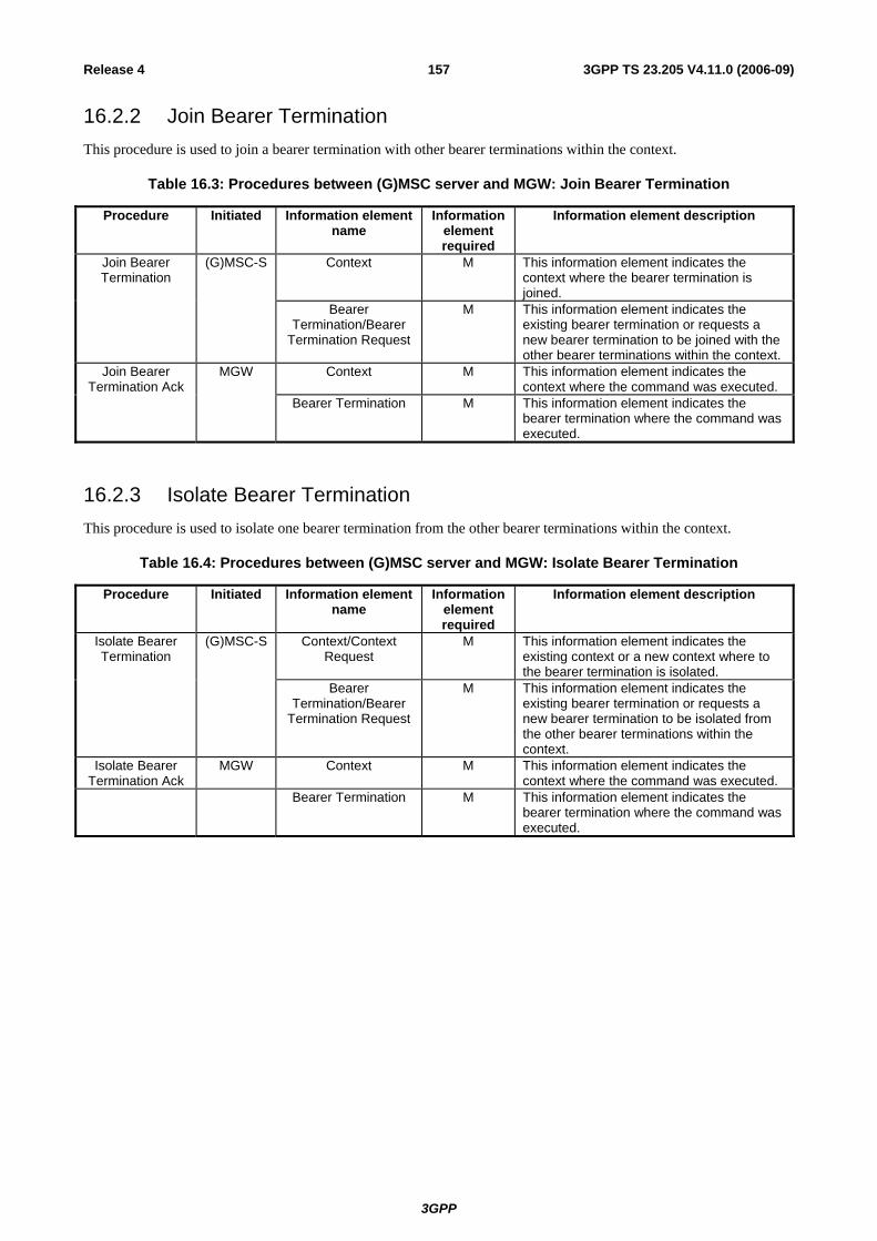
3GPP
3GPP TS 23.205 V4.11.0 (2006-09)157Release 4
16.2.2 Join Bearer Termination This procedure is used to join a bearer termination with other bearer terminations within the context.
Table 16.3: Procedures between (G)MSC server and MGW: Join Bearer Termination
Procedure Initiated Information element name
Information element required
Information element description
Join Bearer Termination
(G)MSC-S Context M This information element indicates the context where the bearer termination is joined.
Bearer Termination/Bearer
Termination Request
M This information element indicates the existing bearer termination or requests a new bearer termination to be joined with the other bearer terminations within the context.
Join Bearer Termination Ack
MGW Context M This information element indicates the context where the command was executed.
Bearer Termination M This information element indicates the bearer termination where the command was executed.
16.2.3 Isolate Bearer Termination This procedure is used to isolate one bearer termination from the other bearer terminations within the context.
Table 16.4: Procedures between (G)MSC server and MGW: Isolate Bearer Termination
Procedure Initiated Information element name
Information element required
Information element description
Isolate Bearer Termination
(G)MSC-S Context/Context Request
M This information element indicates the existing context or a new context where to the bearer termination is isolated.
Bearer Termination/Bearer
Termination Request
M This information element indicates the existing bearer termination or requests a new bearer termination to be isolated from the other bearer terminations within the context.
Isolate Bearer Termination Ack
MGW Context M This information element indicates the context where the command was executed.
Bearer Termination M This information element indicates the bearer termination where the command was executed.

3GPP
3GPP TS 23.205 V4.11.0 (2006-09)158Release 4
16.2.4 Establish Bearer This procedure is used to request a bearer establishment.
Table 16.5: Procedures between (G)MSC server and MGW: Establish Bearer
Procedure Initiated Information element name
Information element required
Information element description
Establish Bearer (G)MSC-S Context/Context Request
M This information element indicates the existing context or requests a new context for the bearer termination.
Bearer Termination/Bearer
Termination Request
M This information element indicates the existing bearer termination or requests a new bearer termination for the bearer to be established.
Bearer Establishment Request
M This information element requests establishment of a bearer.
Destination Binding Reference
M This information element indicates the bearer identifier in the destination MGW.
Destination Bearer Address
M This information element indicates the bearer address of the destination MGW.
Bearer Characteristics
M This information element indicates the characteristics of the bearer connection.
Bearer Service Characteristics
C This information element indicates the bearer service requested by the user. This information element is included if neither Codec information element nor Circuit Switched Data information elements are provided.
Notify Established Bearer
O This information element requests a notification of an established bearer.
Tunnel Support O This information element indicates the support of tunnel data transfer and when to send tunnel data.
Circuit Switched Data C This information element indicates the PLMN bearer capabilities and when applicable GSM channel coding. This information element is included for a non-speech call by the MSC server, or by the anchor-MSC in case of inter-MSC handover, for a radio access network side bearer termination.
Framing Protocol O This information element indicates the framing protocol to be used for the bearer.
Establish Bearer Ack
MGW Context M This information element indicates the context where the command was executed.
Bearer Termination M This information element indicates the bearer termination where the command was executed.
Tunnel Usage O This information element indicates the usage of tunnel data transfer in the call control protocol.

3GPP
3GPP TS 23.205 V4.11.0 (2006-09)159Release 4
16.2.5 Prepare Bearer This procedure is used to prepare for a bearer establishment.
Table 16.6: Procedures between (G)MSC server and MGW: Prepare Bearer
Procedure Initiated Information element name
Information element required
Information element description
Prepare Bearer (G)MSC-S Context/Context Request
M This information element indicates the existing context or requests a new context for the bearer termination.
Bearer Termination Request
M This information element requests a new bearer termination for the bearer to be established.
Binding Reference Request
M This information element requests the bearer identifier in the MGW.
Bearer Address Request
M This information element requests the bearer address of the MGW.
Sender Binding Reference
O This information element indicates the bearer identifier of the sending MGW.
Sender Bearer Address
O This information element indicates the bearer address of the sending MGW.
Bearer Characteristics/
Bearer Characteristics
Requests
M This information element indicates the preferred characteristics of the bearer connection or requests the MGW to select and provide the bearer characteristics.
Bearer Service Characteristics
C This information element indicates the bearer service requested by the user. This information element is included if neither Codec information element nor Circuit Switched Data information elements are provided.
Notify Established Bearer
O This information element requests a notification of an established bearer.
Notify Bearer Modification
O This information element requests a notification that bearer modification of the
established bearer is allowed. This information element is included for access
bearer assignment. Tunnel Support O This information element indicates the
support of tunnel data transfer and when to send tunnel data.
Circuit Switched Data C This information element indicates the PLMN bearer capabilities and when applicable GSM channel coding. This information element is included for a non-speech call by the MSC server, or by the anchor-MSC in case of inter-MSC handover, for a radio access network side bearer termination.
Codec C This information element indicates the speech coding format to be used for the bearer. This information element is included for a speech call for a radio access network side bearer termination.
Framing Protocol O This information element indicates the framing protocol to be used for the bearer.
Prepare Bearer Ack
MGW Context M This information element indicates the context where the command was executed.
Bearer Termination M This information element indicates the bearer termination where the command was executed.
Binding Reference M This information element indicates the bearer identifier in the MGW.

3GPP
3GPP TS 23.205 V4.11.0 (2006-09)160Release 4
Bearer Address M This information element indicates the bearer address of the MGW
Bearer Characteristics
C This information element indicates the characteristics of the bearer connection. This information element is included, if requested by the (G)MSC server or changed from the (G)MSC server preferred one.
Tunnel Usage O This information element indicates the usage of tunnel data transfer in the call control protocol.
16.2.6 Reserve Circuit This procedure is used to select a TDM circuit in the MGW.
Table 16.7: Procedures between (G)MSC server and MGW: Reserve Circuit
Procedure Initiated Information element name
Information element required
Information element description
Reserve Circuit (G)MSC-S Context/Context Request
M This information element indicates the existing context or requests a new context for the bearer termination.
Bearer Termination M This information element indicates the physical bearer termination for the TDM circuit.
Circuit Switched Data C This information element indicates the PLMN bearer capabilities and GSM channel coding. This information element is included for a non-speech call by the MSC server, or by the anchor-MSC in case of inter-MSC handover, for a radio access network side bearer termination.
Bearer Service Characteristics
C This information element indicates the bearer service requested by the user. This information element is included if no Circuit Switched Data information element is provided.
Reserve Circuit Ack
MGW Context M This information element indicates the context where the command was executed.
Bearer Termination M This information element indicates the bearer termination where the command was executed..
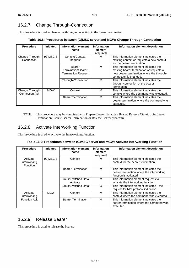
3GPP
3GPP TS 23.205 V4.11.0 (2006-09)161Release 4
16.2.7 Change Through-Connection This procedure is used to change the through-connection in the bearer termination.
Table 16.8: Procedures between (G)MSC server and MGW: Change Through-Connection
Procedure Initiated Information element name
Information element required
Information element description
Change Through-Connection
(G)MSC-S Context/Context Request
M This information element indicates the existing context or requests a new context for the bearer termination.
Bearer Termination/Bearer
Termination Request
M This information element indicates the existing bearer termination or requests a new bearer termination where the through-connection is changed.
Through-Connection M This information element indicates the through-connection of the bearer termination.
Change Through-Connection Ack
MGW Context M This information element indicates the context where the command was executed.
Bearer Termination M This information element indicates the bearer termination where the command was executed.
NOTE: This procedure may be combined with Prepare Bearer, Establish Bearer, Reserve Circuit, Join Bearer Termination, Isolate Bearer Termination or Release Bearer procedure.
16.2.8 Activate Interworking Function This procedure is used to activate the interworking function.
Table 16.9: Procedures between (G)MSC server and MGW: Activate Interworking Function
Procedure Initiated Information element name
Information element required
Information element description
Activate Interworking
Function
(G)MSC-S Context M This information element indicates the context for the bearer termination.
Bearer Termination M This information element indicates the bearer termination where the interworking function is activated.
Circuit Switched Data Activate
M This information element requests to activate the interworking function.
Circuit Switched Data O This information element indicates the request for IWF protocol indication.
Activate Interworking
MGW Context M This information element indicates the context where the command was executed.
Function Ack Bearer Termination M This information element indicates the bearer termination where the command was executed.
16.2.9 Release Bearer This procedure is used to release the bearer.

3GPP
3GPP TS 23.205 V4.11.0 (2006-09)162Release 4
Table 16.10: Procedures between (G)MSC server and MGW: Release Bearer
Procedure Initiated Information element name
Information element required
Information element description
Release Bearer (G)MSC-S Context M This information element indicates the context for the bearer termination.
Bearer Termination M This information element indicates the bearer termination for the bearer to be released.
Bearer Release Request
M This information element requests release of a bearer.
Release Cause O This information element indicates the cause of a bearer release.
Release Bearer Ack
MGW Context M This information element indicates the context where the command was executed.
Bearer Termination M This information element indicates the bearer termination where the command was executed.
16.2.10 Bearer Established This procedure is used to notify the established bearer.
Table 16.11: Procedures between (G)MSC server and MGW: Bearer Established
Procedure Initiated Information element name
Information element required
Information element description
Bearer Established
MGW Context M This information element indicates the context for the bearer termination.
Bearer Termination M This information element indicates the bearer termination where the bearer was established.
Bearer Established M This information element notifies a bearer establishment.
Bearer Established Ack
(G)MSC-S Context M This information element indicates the context where the command was executed.
Bearer Termination M This information element indicates the Bearer Termination where the command was executed.
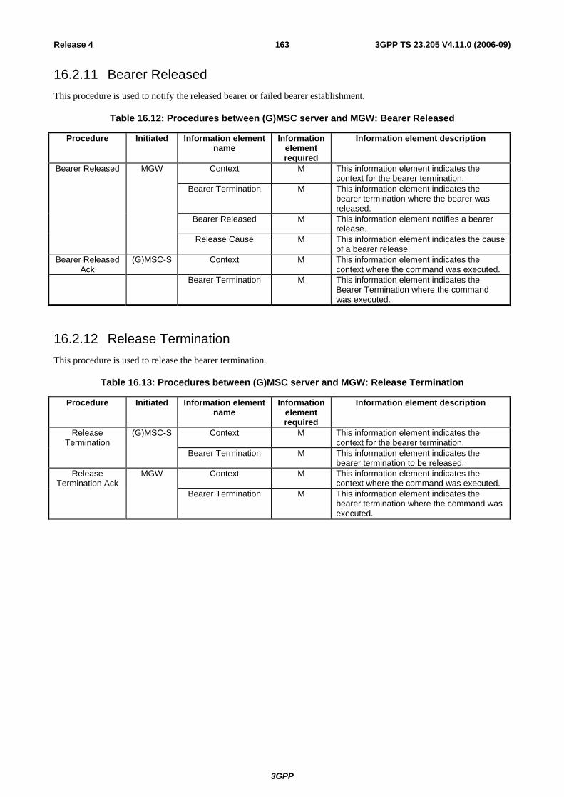
3GPP
3GPP TS 23.205 V4.11.0 (2006-09)163Release 4
16.2.11 Bearer Released This procedure is used to notify the released bearer or failed bearer establishment.
Table 16.12: Procedures between (G)MSC server and MGW: Bearer Released
Procedure Initiated Information element name
Information element required
Information element description
Bearer Released MGW Context M This information element indicates the context for the bearer termination.
Bearer Termination M This information element indicates the bearer termination where the bearer was released.
Bearer Released M This information element notifies a bearer release.
Release Cause M This information element indicates the cause of a bearer release.
Bearer Released Ack
(G)MSC-S Context M This information element indicates the context where the command was executed.
Bearer Termination M This information element indicates the Bearer Termination where the command was executed.
16.2.12 Release Termination This procedure is used to release the bearer termination.
Table 16.13: Procedures between (G)MSC server and MGW: Release Termination
Procedure Initiated Information element name
Information element required
Information element description
Release Termination
(G)MSC-S Context M This information element indicates the context for the bearer termination.
Bearer Termination M This information element indicates the bearer termination to be released.
Release Termination Ack
MGW Context M This information element indicates the context where the command was executed.
Bearer Termination M This information element indicates the bearer termination where the command was executed.
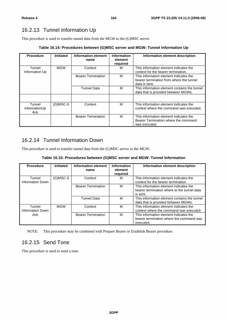
3GPP
3GPP TS 23.205 V4.11.0 (2006-09)164Release 4
16.2.13 Tunnel Information Up This procedure is used to transfer tunnel data from the MGW to the (G)MSC server.
Table 16.14: Procedures between (G)MSC server and MGW: Tunnel Information Up
Procedure Initiated Information element name
Information element required
Information element description
Tunnel Information Up
MGW Context M This information element indicates the context for the bearer termination.
Bearer Termination M This information element indicates the bearer termination from where the tunnel data is sent.
Tunnel Data M This information element contains the tunnel data that is provided between MGWs.
Tunnel InformationUp
Ack
(G)MSC-S Context M This information element indicates the context where the command was executed.
Bearer Termination M This information element indicates the Bearer Termination where the command was executed.
16.2.14 Tunnel Information Down This procedure is used to transfer tunnel data from the (G)MSC server to the MGW.
Table 16.15: Procedures between (G)MSC server and MGW: Tunnel Information
Procedure Initiated Information element name
Information element required
Information element description
Tunnel Information Down
(G)MSC-S Context M This information element indicates the context for the bearer termination.
Bearer Termination M This information element indicates the bearer termination where to the tunnel data is sent.
Tunnel Data M This information element contains the tunnel data that is provided between MGWs.
Tunnel Information Down
MGW Context M This information element indicates the context where the command was executed.
Ack Bearer Termination M This information element indicates the bearer termination where the command was executed.
NOTE: This procedure may be combined with Prepare Bearer or Establish Bearer procedure.
16.2.15 Send Tone This procedure is used to send a tone.

3GPP
3GPP TS 23.205 V4.11.0 (2006-09)165Release 4
Table 16.16: Procedures between (G)MSC server and MGW: Send Tone
Procedure Initiated Information element name
Information element required
Information element description
Send Tone (G)MSC-S Context M This information element indicates the context for the bearer termination.
Bearer Termination/Bearer
Termination Request
M This information element indicates the existing bearer termination or requests a new bearer termination where the tone is sent.
Tone M This information element indicates the tone to be generated.
Notify Tone Completion
O This information element requests a notification of a completed tone.
Tone Direction O This information element indicates the tone direction in the bearer termination.
Tone Timing O This information element indicates the time for the tone.
Send Tone Ack MGW Context M This information element indicates the context where the command was executed.
Bearer Termination M This information element indicates the bearer termination where the command was executed.
NOTE: This procedure may be combined with Join Bearer Termination or Isolate Bearer Termination procedure.
16.2.16 Stop Tone This procedure is used to stop the tone.
Table 16.17: Procedures between (G)MSC server and MGW: Stop Tone
Procedure Initiated Information element name
Information element required
Information element description
Stop Tone (G)MSC-S Context M This information element indicates the context for the bearer termination.
Bearer Termination M This information element indicates the bearer termination where the tone is stopped.
Stop Tone M This information element requests that tone generation is stopped.
Stop Tone Ack MGW Context M This information element indicates the context where the command was executed.
Bearer Termination M This information element indicates the bearer termination where the command was executed.
16.2.17 Play Announcement This procedure is used to play an announcement.

3GPP
3GPP TS 23.205 V4.11.0 (2006-09)166Release 4
Table 16.18: Procedures between (G)MSC server and MGW: Play Announcement
Procedure Initiated Information element name
Information element required
Information element description
Play Announcement
(G)MSC-S Context M This information element indicates the context for the bearer termination.
Bearer Termination/Bearer
Termination Request
M This information element indicates the existing bearer termination or requests a new bearer termination where the announcement is sent.
Announcement M This information element indicates the announcement to be played.
Notify Announcement Completion
O This information element requests a notification of a completed announcement.
Announcement Direction
O This information element indicates the announcement direction in the bearer termination.
Announcement Timing
O This information element indicates the time for the announcement.
Play Announcement
MGW Context M This information element indicates the context where the command was executed.
Ack Bearer Termination M This information element indicates the bearer termination where the command was executed.
NOTE: This procedure may be combined with Join Bearer Termination or Isolate Bearer Termination procedure.
16.2.18 Stop Announcement This procedure is used to stop the announcement.
Table 16.19: Procedures between (G)MSC server and MGW: Stop Announcement
Procedure Initiated Information element name
Information element required
Information element description
Stop Announcement
(G)MSC-S Context M This information element indicates the context for the bearer termination.
Bearer Termination M This information element indicates the bearer termination where the announcement is stopped.
Stop Announcement M This information element requests that announcement playing is stopped.
Stop Announcement
MGW Context M This information element indicates the context where the command was executed.
Ack Bearer Termination M This information element indicates the bearer termination where the command was executed.

3GPP
3GPP TS 23.205 V4.11.0 (2006-09)167Release 4
16.2.19 Announcement Completed This procedure is used to notify the completed announcement.
Table 16.20: Procedures between (G)MSC server and MGW: Announcement Completed
Procedure Initiated Information element name
Information element required
Information element description
Announcement Completed
MGW Context M This information element indicates the context for the bearer termination.
Bearer Termination M This information element indicates the bearer termination where the announcement was completed.
Announcement Completed
M This information element indicates completion of the announcement.
Announcement Completed Ack
(G)MSC-S Context M This information element indicates the context where the command was executed.
Bearer Termination M This information element indicates the Bearer Termination where the command was executed.
16.2.20 Tone Completed This procedure is used to notify the completed tone.
Table 16.21: Procedures between (G)MSC server and MGW: Tone Completed
Procedure Initiated Information element name
Information element required
Information element description
Tone Completed MGW Context M This information element indicates the context for the bearer termination.
Bearer Termination M This information element indicates the bearer termination where the tone was completed.
Tone Completed M This information element indicates completion of the tone.
Tone Completed Ack
(G)MSC-S Context M This information element indicates the context where the command was executed.
Bearer Termination M This information element indicates the Bearer Termination where the command was executed.
16.2.21 Detect DTMF This procedure is used to request detection of a DTMF tone.
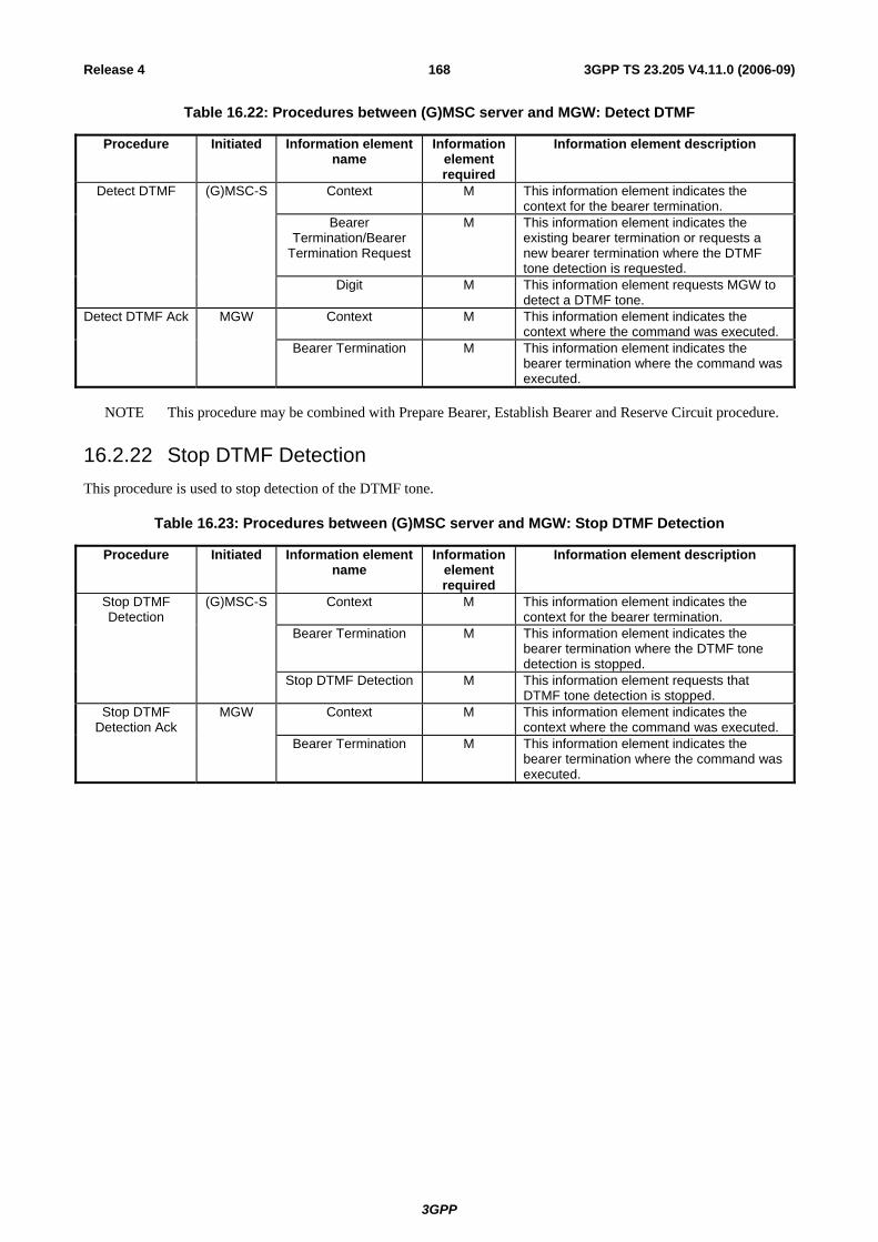
3GPP
3GPP TS 23.205 V4.11.0 (2006-09)168Release 4
Table 16.22: Procedures between (G)MSC server and MGW: Detect DTMF
Procedure Initiated Information element name
Information element required
Information element description
Detect DTMF (G)MSC-S Context M This information element indicates the context for the bearer termination.
Bearer Termination/Bearer
Termination Request
M This information element indicates the existing bearer termination or requests a new bearer termination where the DTMF tone detection is requested.
Digit M This information element requests MGW to detect a DTMF tone.
Detect DTMF Ack MGW Context M This information element indicates the context where the command was executed.
Bearer Termination M This information element indicates the bearer termination where the command was executed.
NOTE This procedure may be combined with Prepare Bearer, Establish Bearer and Reserve Circuit procedure.
16.2.22 Stop DTMF Detection This procedure is used to stop detection of the DTMF tone.
Table 16.23: Procedures between (G)MSC server and MGW: Stop DTMF Detection
Procedure Initiated Information element name
Information element required
Information element description
Stop DTMF Detection
(G)MSC-S Context M This information element indicates the context for the bearer termination.
Bearer Termination M This information element indicates the bearer termination where the DTMF tone detection is stopped.
Stop DTMF Detection M This information element requests that DTMF tone detection is stopped.
Stop DTMF Detection Ack
MGW Context M This information element indicates the context where the command was executed.
Bearer Termination M This information element indicates the bearer termination where the command was executed.

3GPP
3GPP TS 23.205 V4.11.0 (2006-09)169Release 4
16.2.23 Report DTMF This procedure is used to report a detected DTMF tone.
Table 16.24: Procedures between (G)MSC server and MGW: Report DTMF
Procedure Initiated Information element name
Information element required
Information element description
Report DTMF MGW Context M This information element indicates the context for the bearer termination.
Bearer Termination M This information element indicates the bearer termination where the DTMF tone was detected.
Digit M This information element reports the detected DTMF tone.
Report DTMF Ack
(G)MSC-S Context M This information element indicates the context where the command was executed.
Bearer Termination M This information element indicates the Bearer Termination where the command was executed.
16.2.24 Send DTMF This procedure is used to request sending of a DTMF tone.
Table 16.25: Procedures between (G)MSC server and MGW: Send DTMF
Procedure Initiated Information element name
Information element required
Information element description
Send DTMF (G)MSC-S Context M This information element indicates the context for the bearer termination.
Bearer Termination/Bearer
Termination Request
M This information element indicates the existing bearer termination or requests a new bearer termination where the DTMF tone generation is requested.
Digit M This information element requests MGW to generate a DTMF tone.
DTMF Tone Timing O This information element indicates the time for the DTMF tone in the bearer termination.
Send DTMF Ack MGW Context M This information element indicates the context where the command was executed.
Bearer Termination M This information element indicates the bearer termination where the command was executed.

3GPP
3GPP TS 23.205 V4.11.0 (2006-09)170Release 4
16.2.25 Stop DTMF This procedure is used to stop sending of the DTMF tone.
Table 16.26: Procedures between (G)MSC server and MGW: Stop DTMF
Procedure Initiated Information element name
Information element required
Information element description
Stop DTMF (G)MSC-S Context M This information element indicates the context for the bearer termination.
Bearer Termination M This information element indicates the bearer termination where the DTMF tone generation is stopped.
Stop DTMF M This information element requests that DTMF tone generation is stopped.
Stop DTMF Ack MGW Context M This information element indicates the context where the command was executed.
Bearer Termination M This information element indicates the bearer termination where the command was executed.
16.2.26 MGW Out-of-Service This procedure is used to indicate that the MGW will go out of service.
Table 16.27: Procedures between (G)MSC server and MGW: MGW Out-of-Service
Procedure Initiated Information element name
Information element required
Information element description
MGW Out-of-Service
MGW Context M This information element indicates the context for the command.
Root Termination M This information element indicates the root termination for the command.
Reason M This information element indicates the reason for service change.
Method M This information element indicates the method for service change.
MGW Out-of-Service Ack
(G)MSC-S Context M This information element indicates the context where the command was executed.
Root Termination M This information element indicates the root termination where the command was executed.

3GPP
3GPP TS 23.205 V4.11.0 (2006-09)171Release 4
16.2.27 MGW Communication Up This procedure is used to indicate that the MGW is back in service.
Table 16.28: Procedures between (G)MSC server and MGW: MGW Communication Up
Procedure Initiated Information element name
Information element required
Information element description
MGW Communication
Up
MGW Context M This information element indicates the context for the command.
Root Termination M This information element indicates the root termination for the command.
Reason M This information element indicates the reason for service change.
Method M This information element indicates the method for service change.
MGW Communication
(G)MSC-S Context M This information element indicates the context where the command was executed.
Up Ack Root Termination M This information element indicates the root termination where the command was executed.
16.2.28 MGW Restoration This procedure is used to indicate the MGW failure or recovery.
Table 16.29: Procedures between (G)MSC server and MGW: MGW Restoration
Procedure Initiated Information element name
Information element required
Information element description
MGW Restoration
MGW Context M This information element indicates the context for the command.
Root Termination M This information element indicates the root termination for the command.
Reason M This information element indicates the reason for the service change.
Method M This information element indicates the method for service change.
MGW Restoration Ack
(G)MSC-S Context M This information element indicates the context where the command was executed.
Root Termination M This information element indicates the root termination where the command was executed.
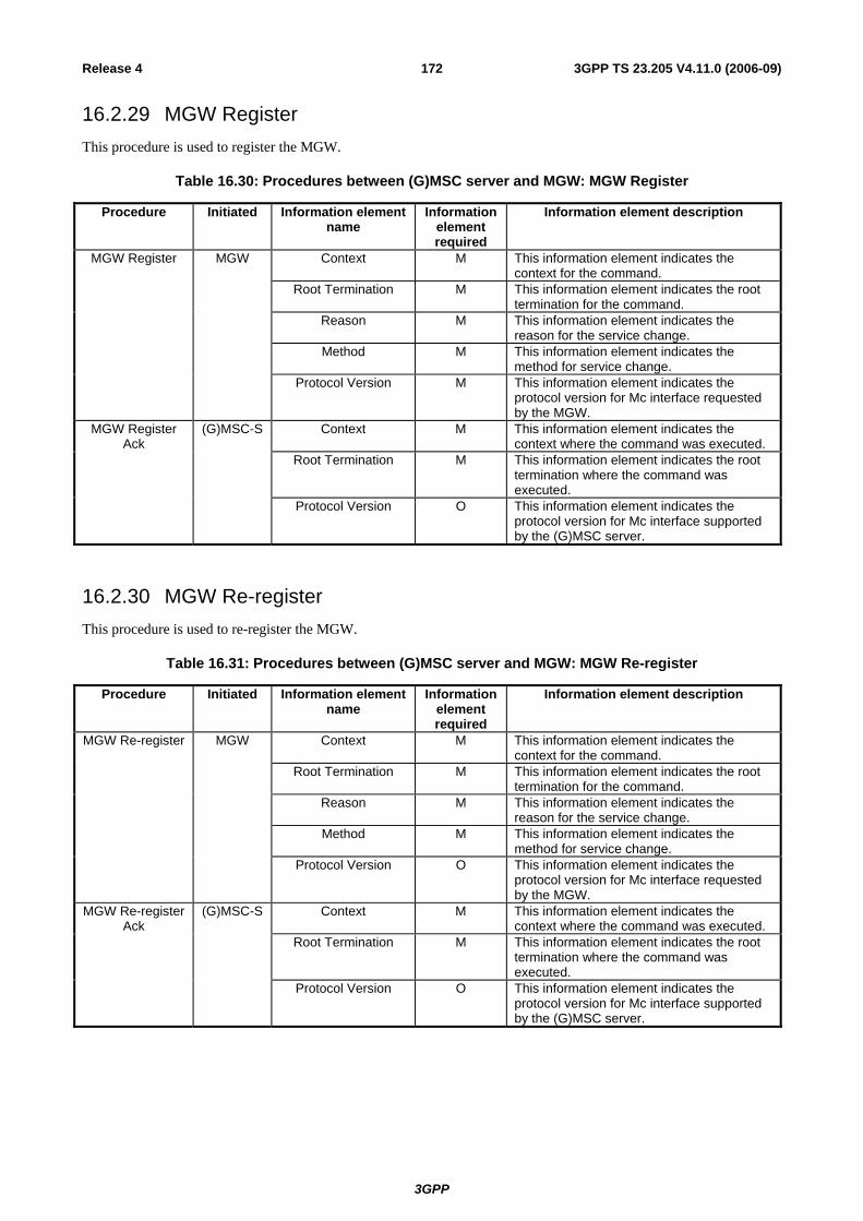
3GPP
3GPP TS 23.205 V4.11.0 (2006-09)172Release 4
16.2.29 MGW Register This procedure is used to register the MGW.
Table 16.30: Procedures between (G)MSC server and MGW: MGW Register
Procedure Initiated Information element name
Information element required
Information element description
MGW Register MGW Context M This information element indicates the context for the command.
Root Termination M This information element indicates the root termination for the command.
Reason M This information element indicates the reason for the service change.
Method M This information element indicates the method for service change.
Protocol Version M This information element indicates the protocol version for Mc interface requested by the MGW.
MGW Register Ack
(G)MSC-S Context M This information element indicates the context where the command was executed.
Root Termination M This information element indicates the root termination where the command was executed.
Protocol Version O This information element indicates the protocol version for Mc interface supported by the (G)MSC server.
16.2.30 MGW Re-register This procedure is used to re-register the MGW.
Table 16.31: Procedures between (G)MSC server and MGW: MGW Re-register
Procedure Initiated Information element name
Information element required
Information element description
MGW Re-register MGW Context M This information element indicates the context for the command.
Root Termination M This information element indicates the root termination for the command.
Reason M This information element indicates the reason for the service change.
Method M This information element indicates the method for service change.
Protocol Version O This information element indicates the protocol version for Mc interface requested by the MGW.
MGW Re-register Ack
(G)MSC-S Context M This information element indicates the context where the command was executed.
Root Termination M This information element indicates the root termination where the command was executed.
Protocol Version O This information element indicates the protocol version for Mc interface supported by the (G)MSC server.
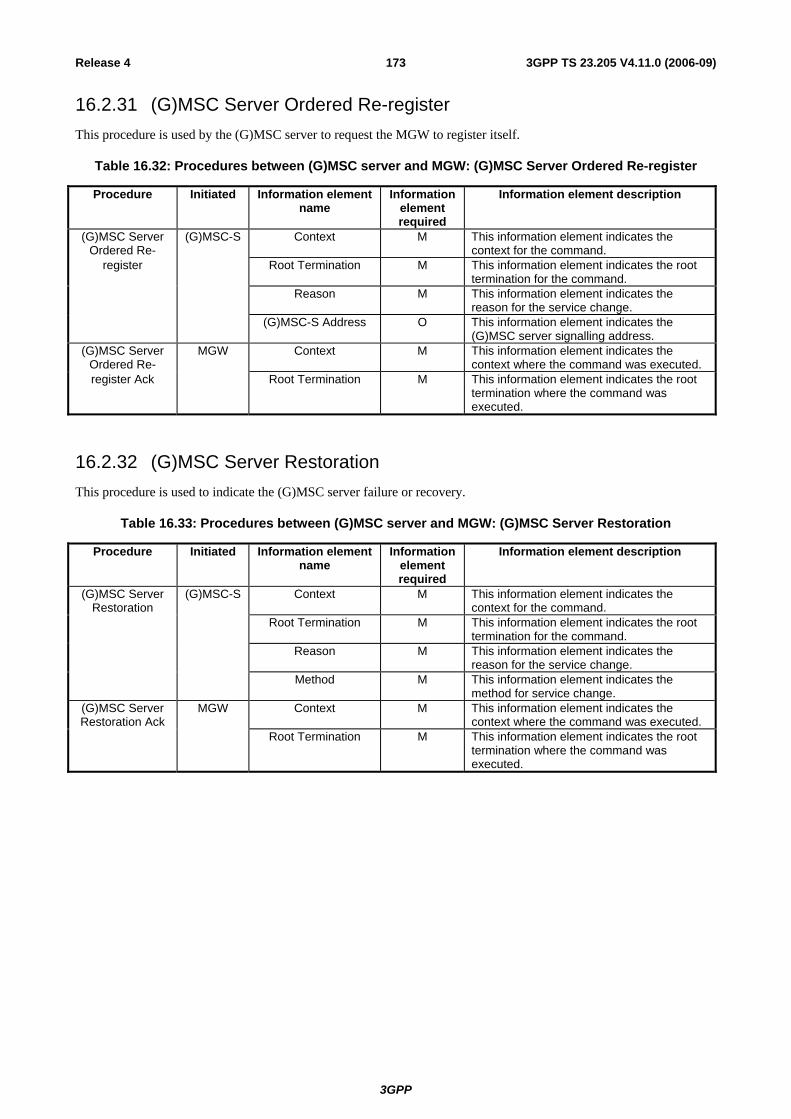
3GPP
3GPP TS 23.205 V4.11.0 (2006-09)173Release 4
16.2.31 (G)MSC Server Ordered Re-register This procedure is used by the (G)MSC server to request the MGW to register itself.
Table 16.32: Procedures between (G)MSC server and MGW: (G)MSC Server Ordered Re-register
Procedure Initiated Information element name
Information element required
Information element description
(G)MSC Server Ordered Re-
(G)MSC-S Context M This information element indicates the context for the command.
register Root Termination M This information element indicates the root termination for the command.
Reason M This information element indicates the reason for the service change.
(G)MSC-S Address O This information element indicates the (G)MSC server signalling address.
(G)MSC Server Ordered Re-
MGW Context M This information element indicates the context where the command was executed.
register Ack Root Termination M This information element indicates the root termination where the command was executed.
16.2.32 (G)MSC Server Restoration This procedure is used to indicate the (G)MSC server failure or recovery.
Table 16.33: Procedures between (G)MSC server and MGW: (G)MSC Server Restoration
Procedure Initiated Information element name
Information element required
Information element description
(G)MSC Server Restoration
(G)MSC-S Context M This information element indicates the context for the command.
Root Termination M This information element indicates the root termination for the command.
Reason M This information element indicates the reason for the service change.
Method M This information element indicates the method for service change.
(G)MSC Server Restoration Ack
MGW Context M This information element indicates the context where the command was executed.
Root Termination M This information element indicates the root termination where the command was executed.
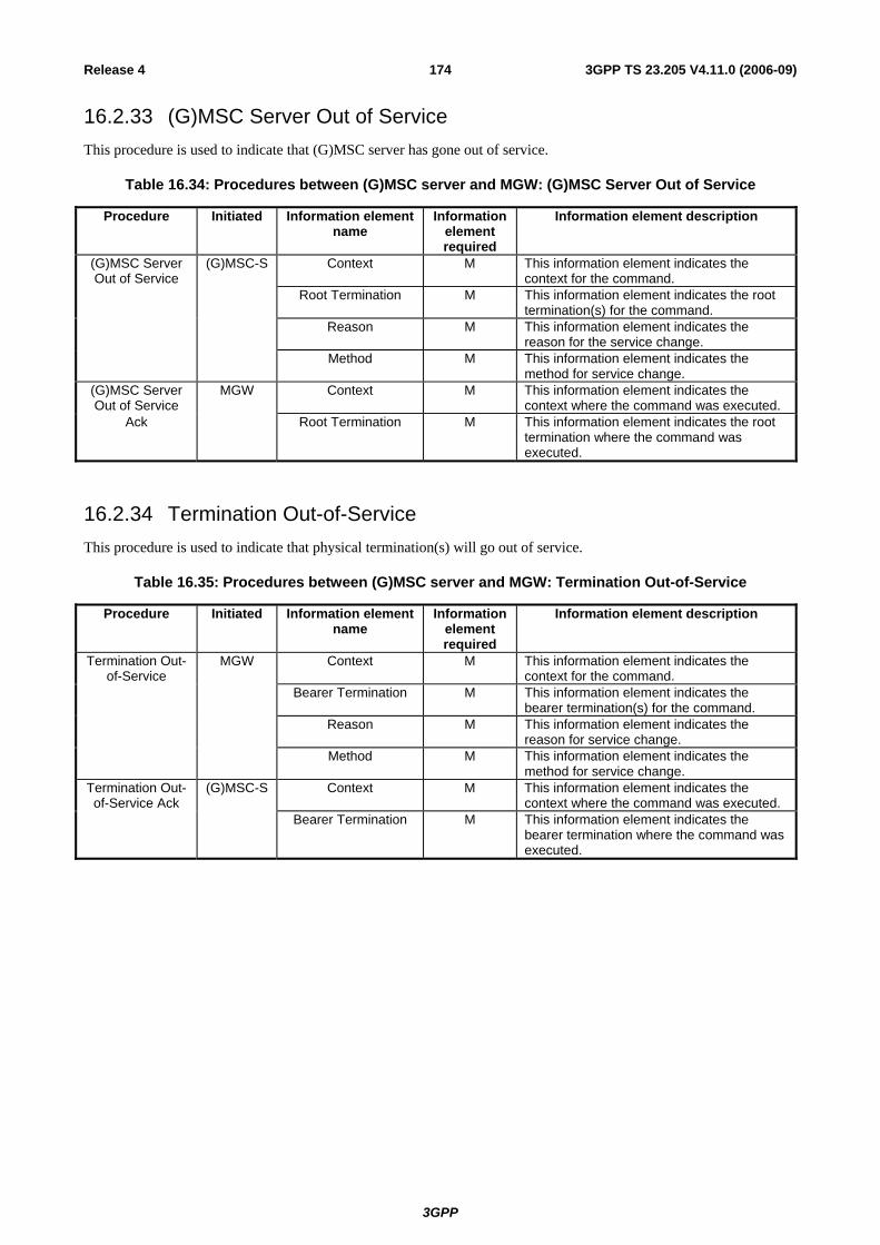
3GPP
3GPP TS 23.205 V4.11.0 (2006-09)174Release 4
16.2.33 (G)MSC Server Out of Service This procedure is used to indicate that (G)MSC server has gone out of service.
Table 16.34: Procedures between (G)MSC server and MGW: (G)MSC Server Out of Service
Procedure Initiated Information element name
Information element required
Information element description
(G)MSC Server Out of Service
(G)MSC-S Context M This information element indicates the context for the command.
Root Termination M This information element indicates the root termination(s) for the command.
Reason M This information element indicates the reason for the service change.
Method M This information element indicates the method for service change.
(G)MSC Server Out of Service
MGW Context M This information element indicates the context where the command was executed.
Ack Root Termination M This information element indicates the root termination where the command was executed.
16.2.34 Termination Out-of-Service This procedure is used to indicate that physical termination(s) will go out of service.
Table 16.35: Procedures between (G)MSC server and MGW: Termination Out-of-Service
Procedure Initiated Information element name
Information element required
Information element description
Termination Out-of-Service
MGW Context M This information element indicates the context for the command.
Bearer Termination M This information element indicates the bearer termination(s) for the command.
Reason M This information element indicates the reason for service change.
Method M This information element indicates the method for service change.
Termination Out-of-Service Ack
(G)MSC-S Context M This information element indicates the context where the command was executed.
Bearer Termination M This information element indicates the bearer termination where the command was executed.

3GPP
3GPP TS 23.205 V4.11.0 (2006-09)175Release 4
16.2.35 Termination Restoration This procedure is used to indicate that physical termination(s) are back in service.
Table 16.36: Procedures between (G)MSC server and MGW: Termination Restoration
Procedure Initiated Information element name
Information element required
Information element description
Termination Restoration
MGW Context M This information element indicates the context for the command.
Bearer Termination M This information element indicates the bearer termination(s) for the command.
Reason M This information element indicates the reason for service change.
Method M This information element indicates the method for service change.
Termination Restoration Ack
(G)MSC-S Context M This information element indicates the context where the command was executed.
Bearer Termination M This information element indicates the bearer termination where the command was executed.
16.2.36 Audit Value This procedure is used to audit values of different object(s).
Table 16.37: Procedures between (G)MSC server and MGW: Audit Value
Procedure Initiated Information element name
Information element required
Information element description
Audit Value (G)MSC-S Context M This information element indicates the context for the command.
Bearer Termination M This information element indicates the bearer termination(s) for the command.
Object(s) M This information element indicates the object(s) to be audited.
Audit Value Ack MGW Context M This information element indicates the context where the command was executed.
Bearer Termination M This information element indicates the bearer termination where the command was executed.
Value(s) M This information element indicates the value(s) of the object(s).
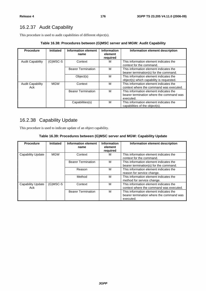
3GPP
3GPP TS 23.205 V4.11.0 (2006-09)176Release 4
16.2.37 Audit Capability This procedure is used to audit capabilities of different object(s).
Table 16.38: Procedures between (G)MSC server and MGW: Audit Capability
Procedure Initiated Information element name
Information element required
Information element description
Audit Capability (G)MSC-S Context M This information element indicates the context for the command.
Bearer Termination M This information element indicates the bearer termination(s) for the command.
Object(s) M This information element indicates the object(s) which capability is requested.
Audit Capability Ack
MGW Context M This information element indicates the context where the command was executed.
Bearer Termination M This information element indicates the bearer termination where the command was executed.
Capabilities(s) M This information element indicates the capabilities of the object(s).
16.2.38 Capability Update This procedure is used to indicate update of an object capability.
Table 16.39: Procedures between (G)MSC server and MGW: Capability Update
Procedure Initiated Information element name
Information element required
Information element description
Capability Update MGW Context M This information element indicates the context for the command.
Bearer Termination M This information element indicates the bearer termination(s) for the command.
Reason M This information element indicates the reason for service change.
Method M This information element indicates the method for service change.
Capability Update Ack
(G)MSC-S Context M This information element indicates the context where the command was executed.
Bearer Termination M This information element indicates the bearer termination where the command was executed.

3GPP
3GPP TS 23.205 V4.11.0 (2006-09)177Release 4
16.2.39 Command Reject This command is used to reject the received command request. It may be used as response to any of the above procedures.
Table 16.40: Procedures between (G)MSC server and MGW: Command Reject
Procedure Initiated Information element name
Information element required
Information element description
Command Reject Both Context M This information element indicates the context where the command was rejected.
Bearer Termination M This information element indicates the bearer termination where the command was rejected.
Error M This information element indicates the error that caused command rejection.
16.2.40 Activate Voice Processing Function This procedure is used to activate the voice processing (i.e., echo cancellation and gain control) function.
Table 16.41: Procedures between (G)MSC server and MGW: Activate Voice Processing Function
Procedure Initiated Information element name
Information element required
Information element description
Activate Voice Processing
(G)MSC-S Context M This information element indicates the context for the bearer termination.
Function Bearer Termination M This information element indicates the bearer termination where the voice processing function is activated.
Activate Voice Processing Function
M This information element requests to activate the voice processing function.
Activate Voice Processing
MGW Context M This information element indicates the context where the command was executed.
Function Ack Bearer Termination M This information element indicates the bearer termination where the command was executed.
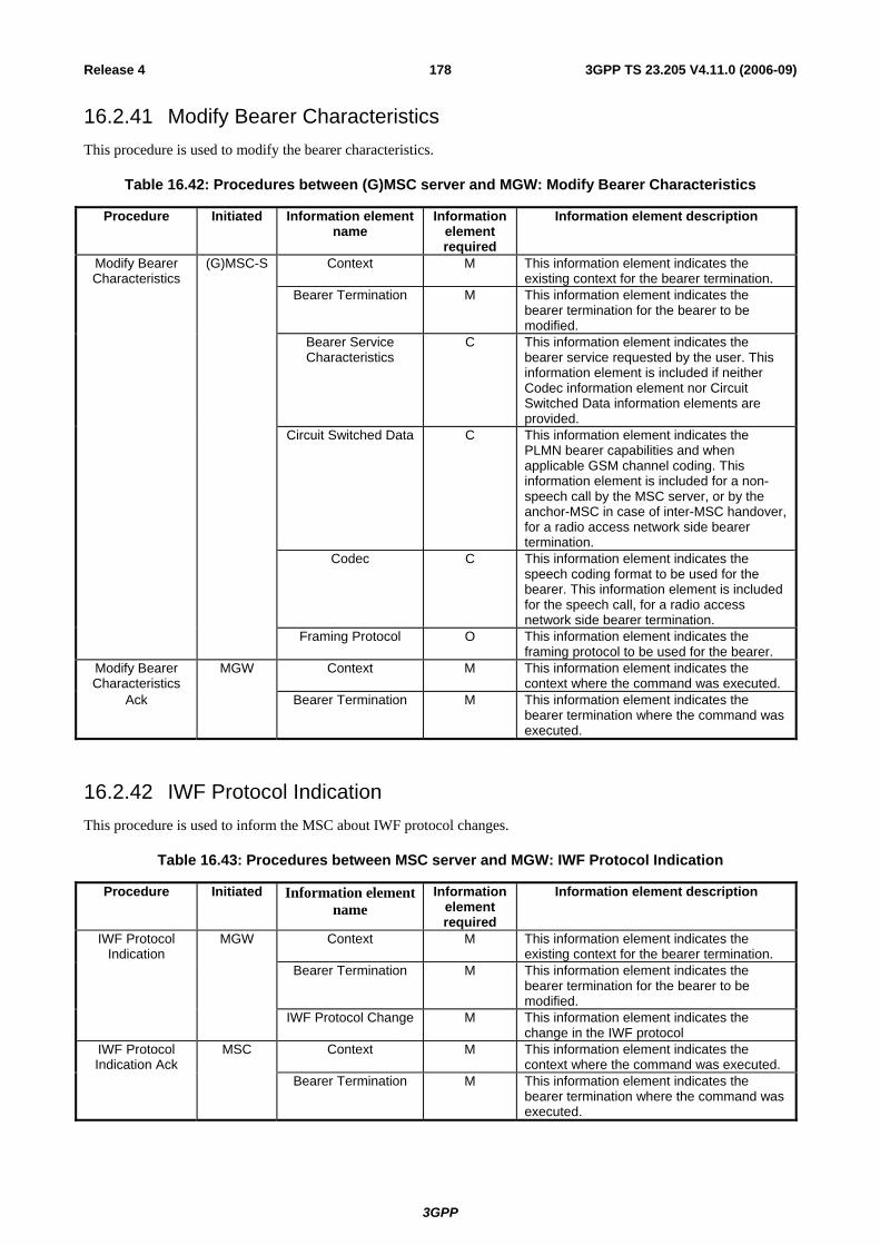
3GPP
3GPP TS 23.205 V4.11.0 (2006-09)178Release 4
16.2.41 Modify Bearer Characteristics This procedure is used to modify the bearer characteristics.
Table 16.42: Procedures between (G)MSC server and MGW: Modify Bearer Characteristics
Procedure Initiated Information element name
Information element required
Information element description
Modify Bearer Characteristics
(G)MSC-S Context M This information element indicates the existing context for the bearer termination.
Bearer Termination M This information element indicates the bearer termination for the bearer to be modified.
Bearer Service Characteristics
C This information element indicates the bearer service requested by the user. This information element is included if neither Codec information element nor Circuit Switched Data information elements are provided.
Circuit Switched Data C This information element indicates the PLMN bearer capabilities and when applicable GSM channel coding. This information element is included for a non-speech call by the MSC server, or by the anchor-MSC in case of inter-MSC handover, for a radio access network side bearer termination.
Codec C This information element indicates the speech coding format to be used for the bearer. This information element is included for the speech call, for a radio access network side bearer termination.
Framing Protocol O This information element indicates the framing protocol to be used for the bearer.
Modify Bearer Characteristics
MGW Context M This information element indicates the context where the command was executed.
Ack Bearer Termination M This information element indicates the bearer termination where the command was executed.
16.2.42 IWF Protocol Indication This procedure is used to inform the MSC about IWF protocol changes.
Table 16.43: Procedures between MSC server and MGW: IWF Protocol Indication
Procedure Initiated Information element name
Information element required
Information element description
IWF Protocol Indication
MGW Context M This information element indicates the existing context for the bearer termination.
Bearer Termination M This information element indicates the bearer termination for the bearer to be modified.
IWF Protocol Change M This information element indicates the change in the IWF protocol
IWF Protocol Indication Ack
MSC Context M This information element indicates the context where the command was executed.
Bearer Termination M This information element indicates the bearer termination where the command was executed.

3GPP
3GPP TS 23.205 V4.11.0 (2006-09)179Release 4
16.2.43 Bearer Modification Support This procedure is used to notify that the established bearer can be modified.
Table 16.44: Procedures between (G)MSC server and MGW: Bearer Modification
Procedure Initiated Information element name
Information element required
Information element description
Context M This information element indicates the context for the bearer termination.
Bearer Termination M This information element indicates the bearer termination where the bearer was established.
Bearer Modification
Support
MGW
Bearer Modification M This information element notifies that the established bearer can be modified.
Bearer Modification Support Ack
(G)MSC-S Context M This information element indicates the context where the command was executed.
Bearer Termination M This information element indicates the Bearer Termination where the command was executed.
16.2.44 Rate Change This procedure is used to notify that the CS data rate should be changed.
Table 16.2.45: Procedures between (G)MSC server and MGW: Rate Change
Procedure Initiated Information element name
Information element required
Information element description
Context M This information element indicates the context for the bearer termination.
Bearer Termination M This information element indicates the bearer termination where the rate change is required.
Rate Change MGW
Rate M This information element notifies the current rate.
Context M This information element indicates the context where the command was executed.
Rate Change Ack (G)MSC-S
Bearer Termination M This information element indicates the bearer termination where the command was executed.
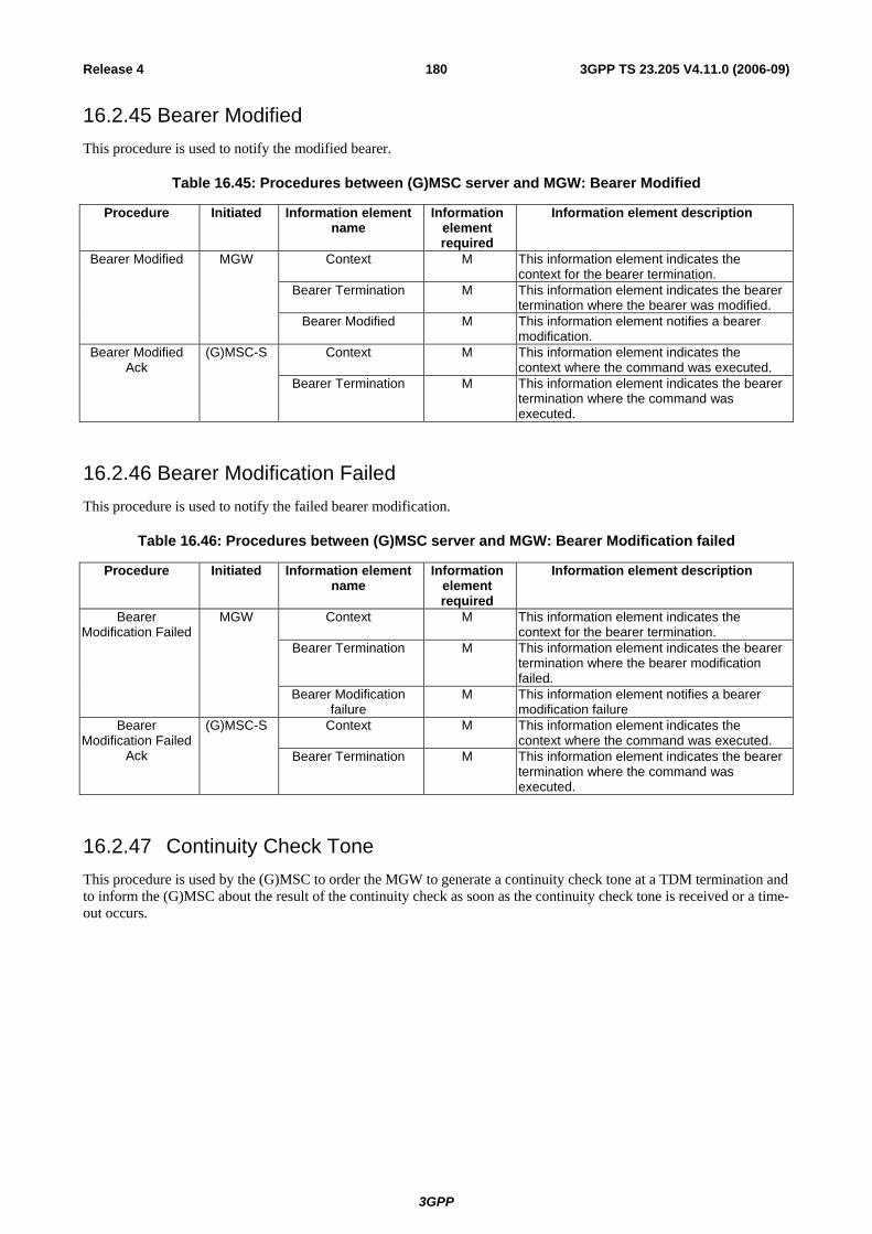
3GPP
3GPP TS 23.205 V4.11.0 (2006-09)180Release 4
16.2.45 Bearer Modified This procedure is used to notify the modified bearer.
Table 16.45: Procedures between (G)MSC server and MGW: Bearer Modified
Procedure Initiated Information element name
Information element required
Information element description
Context M This information element indicates the context for the bearer termination.
Bearer Termination M This information element indicates the bearer termination where the bearer was modified.
Bearer Modified MGW
Bearer Modified M This information element notifies a bearer modification.
Context M This information element indicates the context where the command was executed.
Bearer Modified Ack
(G)MSC-S
Bearer Termination M This information element indicates the bearer termination where the command was executed.
16.2.46 Bearer Modification Failed This procedure is used to notify the failed bearer modification.
Table 16.46: Procedures between (G)MSC server and MGW: Bearer Modification failed
Procedure Initiated Information element name
Information element required
Information element description
Context M This information element indicates the context for the bearer termination.
Bearer Termination M This information element indicates the bearer termination where the bearer modification failed.
Bearer Modification Failed
MGW
Bearer Modification failure
M This information element notifies a bearer modification failure
Context M This information element indicates the context where the command was executed.
Bearer Modification Failed
Ack
(G)MSC-S
Bearer Termination M This information element indicates the bearer termination where the command was executed.
16.2.47 Continuity Check Tone This procedure is used by the (G)MSC to order the MGW to generate a continuity check tone at a TDM termination and to inform the (G)MSC about the result of the continuity check as soon as the continuity check tone is received or a time-out occurs.

3GPP
3GPP TS 23.205 V4.11.0 (2006-09)181Release 4
Table 16.47: Continuity Check Tone procedure
Procedure Initiated Information element name
Information element required
Information element description
Continuity Check Tone
(G)MSC Context/Context Request
M This information element indicates the existing context or requests a new context
for the bearer termination. TDM Termination M This information element indicates the
bearer termination Request for continuity
tone sending M This information request the MGW to apply
the continuity check procedure on the indicated TDM termination
Request for continuity check tone detection
M This information request the MGW to inform of result of the continuity check
procedure on the indicated TDM termination
Continuity Check Tone Ack
IMGW Context M This information element indicates the context where the command was executed.
16.2.48 Continuity Check Verify This procedure is used by the MGW to indicate towards the (G)MSC that the continuity check at a TDM termination has been completed and to return the result of the check: success or failure.
Table 16.48: Continuity Check Verify procedure
Procedure Initiated Information element name
Information element required
Information element description
Continuity check Verify
MGW Context/t M This information element indicates the context where the command was executed.
TDM Termination M This information element indicates the TDM termination involved in the procedure
Outcome of the continuity check
M This information element indicates the outcome of the continuity check
(successful/unsuccessful) Continuity Check
Verify Ack (G)MSC Context M This information element indicates the
context where the command was executed.
16.2.49 Continuity Check Response This procedure is used by the (G)MSC to order the MGW to loop back an incoming continuity check tone at a TDM termination.

3GPP
3GPP TS 23.205 V4.11.0 (2006-09)182Release 4
Table 16.49: Continuity Check Response procedure
Procedure Initiated Information element name
Information element required
Information element description
Continuity Check Response
(G)MSC Context/Context Request
M This information element indicates the existing context or requests a new context
for the bearer termination. TDM Termination M This information element indicates the
bearer termination Request for loop back
of the continuity toneM This information request the MGW to loop
back the continuity check tone on the indicated TDM termination
Continuity Check Response Ack
IMGW Context M This information element indicates the context where the command was executed.
17 Bearer Redirect The BICC [22] Bearer Redirect mechanism may be used for optimising the bearer path when an endpoint of a call changes due to the operation of an application layer service.
17.1 Example of use of Bearer Redirect with Call Forwarding on No Reply (CFNRy)
MGW AMGW G
GMSC-S MSC-S A
RNCCTX1T1 T2
CTX2T3 T4
Before CFNRy:

3GPP
3GPP TS 23.205 V4.11.0 (2006-09)183Release 4
MGW BMGW G
GMSC-S MSC-S A
CTX1T1 T5
CTX2T6 T7
After CFNRy and Bearer Redirection:
MSC-S B
Figure 17.1: CFNRy and Bearer Redirect (Network model)
Figure 17.2 shows the message sequence example for the call forwarding on no reply with Bearer Redirect. In the example, after the call and the bearer towards the access have been released MSC server A requests the MGW A to remove the bearer termination for the served mobile subscriber. MSC server A requests the GMSC server to redirect the bearer to the forwarded to subscriber (interactions towards the access are not shown), using MSC server A as a call control anchor. Once the bearer towards MGW B is established the GMSC server instructs MGW G to connect the incoming bearer to the new bearer (towards MGW B) and informs MSC server A. Once informed that the new bearer has been established MSC server A instructs the GMSC server to removes the old bearer termination (towards MGW A).

3GPP
3GPP TS 23.205 V4.11.0 (2006-09)184Release 4
Context (C3) ADD.reply (T5)
GMSC-S MSC-S A MGW BMGW G MGW A MSC-S B
Bearer Redirection Connect Backwards
Redirect Backwards Request
Prepare Bearer
Normal call and bearer establishment
Expiry of no replycondition timer
Context ($) ADD.request ($)
Initial Address + Bearer Information
Establish BearerContext ($) ADD.request ($)
Context (C4) ADD.reply (T6)
Bearer Establishment
Releaseof Iu
Bearer
Context (C4) NOTIFY.request (T6)
Context (C4) NOTIFY.reply (T6)
Context (C3) NOTIFY.request (T5)
Context (C3) NOTIFY.reply (T5)Bearer Established
Redirect Bearer Connected
Address Complete + Answer
Address Complete + Answer
Context (C1) MOD.request (T5)
Context (C1) MOD.reply (T5)
Redirect Bearer Release Proceed
Context (C2) SUB.request (T3)
Context (C2) SUB.reply (T3)
Redirect Bearer Release Complete
Context (C1) SUB.request (T2)
Context (C1) SUB.reply (T2)
Release Termination
Release Termination
Redirect Bearer Release Request
Figure 17.2: Information flow for CFNRy with Bearer Redirect (message sequence chart)
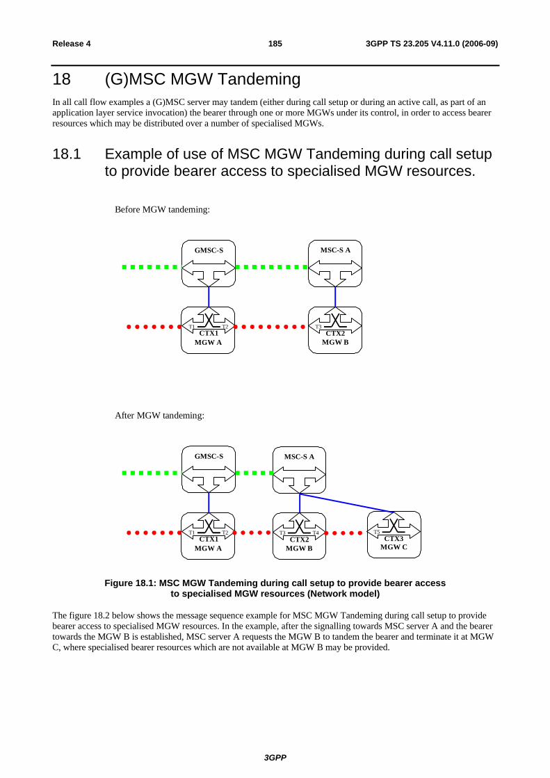
3GPP
3GPP TS 23.205 V4.11.0 (2006-09)185Release 4
18 (G)MSC MGW Tandeming In all call flow examples a (G)MSC server may tandem (either during call setup or during an active call, as part of an application layer service invocation) the bearer through one or more MGWs under its control, in order to access bearer resources which may be distributed over a number of specialised MGWs.
18.1 Example of use of MSC MGW Tandeming during call setup to provide bearer access to specialised MGW resources.
MGW BMGW A
GMSC-S MSC-S A
CTX1T1 T2
CTX2T3
Before MGW tandeming:
MGW CMGW BMGW A
GMSC-S MSC-S A
CTX1T1 T2
CTX3T5
After MGW tandeming:
CTX2T3 T4
Figure 18.1: MSC MGW Tandeming during call setup to provide bearer access to specialised MGW resources (Network model)
The figure 18.2 below shows the message sequence example for MSC MGW Tandeming during call setup to provide bearer access to specialised MGW resources. In the example, after the signalling towards MSC server A and the bearer towards the MGW B is established, MSC server A requests the MGW B to tandem the bearer and terminate it at MGW C, where specialised bearer resources which are not available at MGW B may be provided.

3GPP
3GPP TS 23.205 V4.11.0 (2006-09)186Release 4
GMSC-S MSC-S AMGW A MGW B MGW C
Prepare Bearer
Normal call and bearer establishment
Context (C2) ADD.request ($)
Context (C2) ADD.reply (T4)
Establish BearerContext ($) ADD.request ($)
Context (C3) ADD.reply (T5)
BearerEstablishment
Figure 18.2: MSC MGW Tandeming during call setup to provide bearer access to specialised MGW resources (message sequence chart)
19 Timers for bearer independent CS core network Table 19.1: Timers for bearer independent CS core network
Timer identity
Timer value Timer started Timer stopped Timer expiry
Start_Bearer_Establishment
1 – 14 seconds
Paging procedure is started. Applied only if network side
bearer establishment is delayed until paging
procedure is completed.
Paging procedure is completed or optionally when Call Confirmed message is received.
The network side bearer establishment is started.

3GPP
3GPP TS 23.205 V4.11.0 (2006-09)187Release 4
Annex A (informative): Change History
Change history
Date TSG # TSG Doc. CR Rev Subject/Comment Old New Jul 2000 Initial draft 0.0.1 0.0.2
Aug 2000 Comments from TSG-CN WG4#3 incorporated and draft further elaborated
0.0.2 0.1.0
Sep 2000 Contributions and comments from TSG-CN WG4#4 incorporated and draft further elaborated
0.1.0 0.2.0
Oct 2000 Contributions and comments from TSG-CN WG4 Ad Hoc incorporated and draft further elaborated
0.2.0 1.0.1
Nov 2000 CN#10 For information to TSG-CN #10 1.0.1 1.1.0
Jan 2001 Contributions and comments from TSG-CN WG4 #6 incorporated and draft further elaborated.
1.1.0 1.1.1
Feb 2001 New clause structure for handover, editorial corrections. 1.1.1 1.2.0
Feb 2001 Contributions and comments from TSG-CN WG4 Ad Hoc incorporated.
1.2.0 2.0.0
Mar 2001 CN#11 NP-010081 Contributions and comments from TSG-CN WG4 #7 incorporated.
Approved in CN#11
2.0.0 4.0.0
Jun 2001 CN#12 N4-010676 002 1 Voice Processing Function Alignment/Clean Up for Call Handover and Relocation
4.0.0 4.1.0
Jun 2001 CN#12 N4-010678 004 1 Corrections to Call Clearing 4.0.0 4.1.0
Jun 2001 CN#12 N4-010680 006 1 Alignment of procedure names to TS 29.232 and editorial changes
4.0.0 4.1.0
Sep 2001 CN#13 NP-010452 008 1 Slight Misalignment of Continuity Message Handling 4.1.0 4.2.0
Sep 2001 CN#13 NP-010452 009 Updates to Chapter 9.1 4.1.0 4.2.0
Sep 2001 CN#13 Editorial clean up 4.1.0 4.2.0
Dec 2001 CN#14 NP-010619 012 Correction of Handover/Relocation for Speech and Non-speech calls
4.2.0 4.3.0
Dec 2001 CN#14 NP-010619 014 2 New timer to support long paging in bearer independent network
4.2.0 4.3.0
Dec 2001 CN#14 NP-010619 016 1 Correction for Release of Network Bearer 4.2.0 4.3.0
Mar 2002 CN#15 NP-020029 020 (G)MSC restoration 4.3.0 4.4.0
Mar 2002 CN#15 NP-020029 022 2 Correction of Bearer Modification Handling 4.3.0 4.4.0
Jun 2002 CN#16 NP-020249 027 Correction of an incorrect reference in Section 8.3.3.2 4.4.0 4.5.0
Sep 2002 CN#17 NP-020463 032 1 Correction on wrong message handling for subsequent Handover
4.5.0 4.6.0
Jun 2003 CN#20 NP-020212 41 Clarification of handling of DTMF 4.6.0 4.7.0
Jun 2003 CN#20 NP-020212 43 1 Clarification of handling of DTMF timing 4.6.0 4.7.0
Mar 2005 CN#27 NP-050028 57 Solving contradiction for Release Cause in Release Bearer Procedure between stage 2 and stage 3
4.7.0 4.8.0
Sep 2005 CT#29 CP-050277 069 Correction to Stage 2 to specify FAX 4.8.0 4.9.0
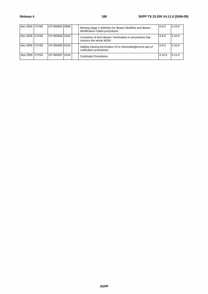
3GPP
3GPP TS 23.205 V4.11.0 (2006-09)188Release 4
Dec 2005 CT#30 CP-050603 0096 Missing stage 2 definition for Bearer Modified and Bearer Modification Failed procedures
4.9.0 4.10.0
Dec 2005 CT#30 CP-050603 0100 Correction of term Bearer Termination in procedures that concern the whole MGW
4.9.0 4.10.0
Dec 2005 CT#30 CP-050603 0103 Adding missing termination ID to Acknowledgement part of notification procedures
4.9.0 4.10.0
Sep 2006 CT#33 CP-060397 0154 Continuity Procedures 4.10.0 4.11.0