3g umts wcdma
DESCRIPTION
uit dfgTRANSCRIPT

Readings related to the subject
• General readings
– WCDMA for UMTS – Harri Holma, Antti Toskala
– HSDPA/HSUPA for UMTS – Harri Holma, Antti Toskala
• Network planning oriented
– Radio Network Planning and Optimisation for UMTS – Janna Laiho, Achim
Wacker, Tomás Novosad
– UMTS Radio Network Planning, Optimization and QoS Management For
Practical Engineering Tasks – Jukka Lempiäinen, Matti Manninen

Outline
• Background
• Key concepts
– Code multiplexing
– Spreading
• Introduction to Wideband Code Division Multiple Access (WCDMA)
• WCDMA Performance Enhancements
– High Speed Packet Access (HSDPA/HSUPA)
– Advanced features for HSDPA

Why new radio access system
• Need for universal standard (Universal Mobile Telecommunication System)
• Support for packet data services – IP data in core network
– Wireless IP
• New services in mobile multimedia need faster data transmission and flexible utilization of the spectrum
• FDMA and TDMA are not efficient enough– TDMA wastes time resources
– FDMA wastes frequency resources
• CDMA can exploit the whole bandwidth constantly
• Wideband CDMA was selected for a radio access system for UMTS (1997)– (Actually the superiority of OFDM was not fully understood by then)

Frequency allocations for UMTS
• Frequency plans of Europe, Japan and Korea are harmonized
• US plan is incompatible, the spectrum reserved for 3G elsewhere is
currently used for the US 2G standards
• IMT-2000 band in Europe:
– FDD 2x60MHz
Expected air interfaces and spectrums, source: “WCDMA for UMTS”

Standardization
• WCDMA was studied in various research programs in the industry and
universities
• WCDMA was chosen besides ETSI also in other forums like ARIB
(Japan) as 3G technology in late 1997/early 1998.
• During 1998 parallel work proceeded in ETSI and ARIB (mainly), with
commonalities but also differences
– Work was also on-going in USA and Korea

Standardization
• At end of 1998 different standardization organizations got together and created 3GPP, 3rd Generation Partnership Project.
– 5 Founding members: ETSI, ARIB+TTC (Japan), TTA (Korea), T1P1 (USA)
– CWTS (China) joined later.
• Different companies are members through their respective standardization organization.
ETSI Members
ETSI
ARIB Members
ARIB
TTA Members
TTA
T1P1 Members
T1P1
TTC Members
TTC
CWTS Members
CWTS
3GPP

WCDMA Background and Evolution
• First major milestone was Release ‘99, 12/99– Full set of specifications by 3GPP– Targeted mainly on access part of the network
• Release 4, 03/01 – Core network was extended– markets jumped over Rel 4
• Release 5, 03/02– High Speed Downlink Packet Access (HSDPA)
• Release 6, end of 04/beginning of 05– High Speed Uplink Packet Access (HSUPA)
• Release 7, 06/07– Continuous Packet connectivity (improvement for e.g. VoIP), advanced features for HSDPA
(MIMO, higher order modulation)

WCDMA Background and Evolution
2000 2002 2004 2006 2007200520032001
3GPP Rel -9912/99
3GPP Rel 4
03/01
3GPP Rel 5 (HSDPA)
03/02
3GPP Rel 6(HSUPA)
2H/04
3GPP Rel 7
HSPA+
06/07Further Releases
JapanEurope
(pre-commercial)Europe
(commercial)
HSDPA (commercial)
HSUPA (commercial)

Evolution of Mobile standards
EDGE
GPRSGSM
HSCSD
cdmaOne(IS-95)
WCDMA FDD
HSDPA/HSUPA
cdma2000
TD-SCDMA TDD LCR
cdma20001XEV - DO
cdma20001XEV - DV
TD-CDMATDD HCR
HSDPA/HSUPA
LTE

Current WCDMA markets• Graph of the technologies adopted by the wireless users worldwide:
• Over 3.5 billion wireless users worldwide
• GSM+WCDMA share currently over 88 % (www.umts-forum.org)
• CDMA share is decreasing every year
GSM (80.9%)
CDMA (12%)
WCDMA (4.6%)
iDEN (0.9%)
PDC (0.8%)
US TDMA (0.8%)
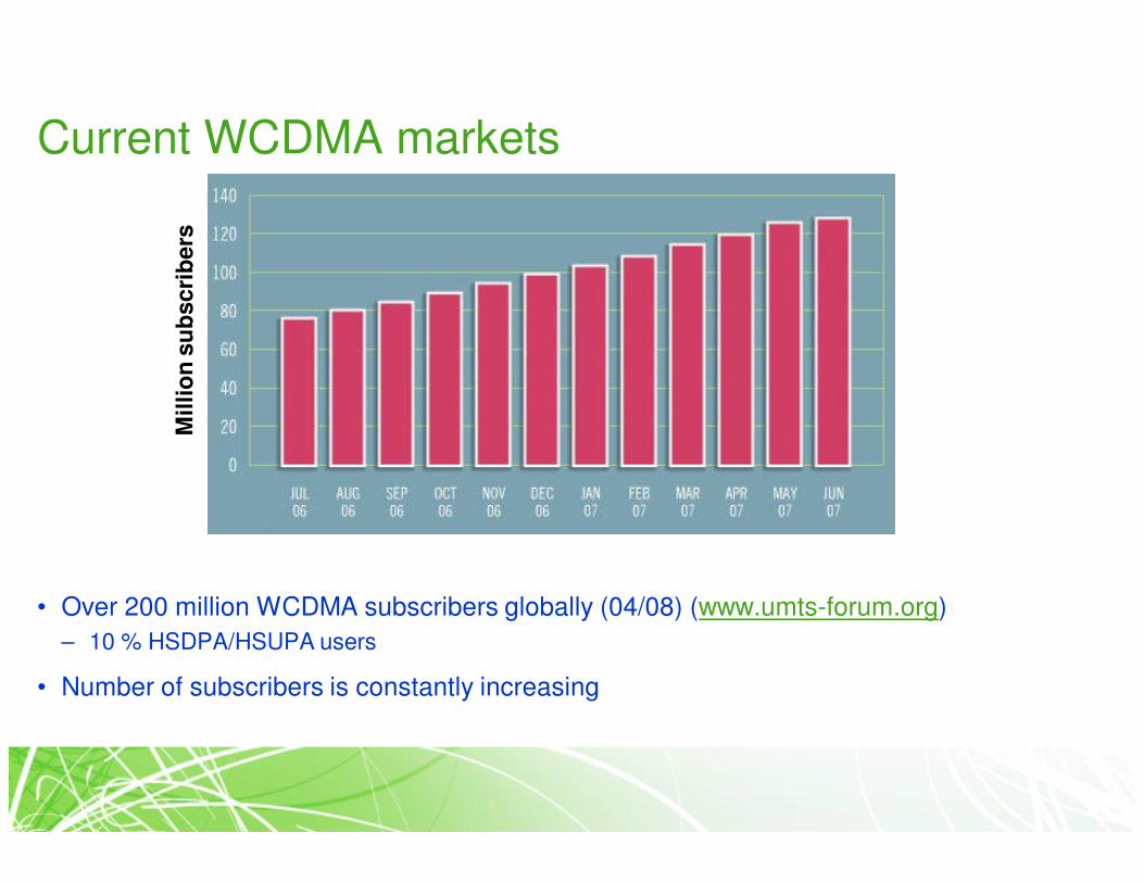
Current WCDMA markets
• Over 200 million WCDMA subscribers globally (04/08) (www.umts-forum.org)
– 10 % HSDPA/HSUPA users
• Number of subscribers is constantly increasing
Mil
lio
n s
ub
scri
bers

Key concepts
• CDMA
• Spread Spectrum
• Direct Sequence spreading
• Spreading and Processing gain

Multiple Access Schemes
• Frequency Division Multiple Access (FDMA), different frequencies for different users– example Nordic Mobile Terminal (NMT) systems
• Time Division Multiple Access (TDMA), same frequency but different timeslots for different users, – example Global System for Mobile Communication (GSM)– GSM also uses FDMA
• Code Division Multiple Access (CDMA), same frequency and time but users are separated from each other with orthogonal codes
Code
Frequency
Time
1
2
N
…
TDMAFDMA CDMA

Spread Spectrum
• Means that the transmission bandwidth is much larger than the information
bandwidth i.e. transmitted signal is spread to a wider bandwidth
– Bandwidth is not dependent on the information signal
• Benefits
– More secure communication
– Reduces the impact of interference (and jamming) due to processing gain
• Classification
– Direct Sequence (spreading with pseudo noise (PN) sequence)
– Frequency hopping (rapidly changing frequency)
– Time Hopping (large frequency, short transmission bursts)
• Direct Sequence is currently commercially most viable

Spread Spectrum
• Where does spread spectrum come from
– First publications, late 40s
– First applications: Military from the 50s
– Rake receiver patent 1956
– Cellular applications proposed late 70s
– Investigations for cellular use 80s
– IS-95 standard 1993 (2G)
– 1997/1998 3G technology choice
– 2001/2002 Commercial launch of WCDMA technology

Direct Sequence
• In direct sequence (DS) user bits are coded with unique binary
sequence i.e. with spreading/channelization code
– The bits of the channelization code are called chips
– Chip rate (W) is typically much higher than bit rate (R)
– Codes need to be in some respect orthogonal to each other (cocktail party
effect)
• Length of a channelization code
– defines how many chips are used to spread a single information bit and thus
determines the end bit rate
– Shorter code equals to higher bit rate but better Signal to Interference and
Noise Ratio (SINR) is required
• Also the shorter the code, the fewer number of codes are available
– Different bit rates have different geographical areas covered based on the
interference levels

Direct Sequence
• Transmission (Tx) side with DS
– Information signal is multiplied with channelization code => spread signal
• Receiving (Rx) side with DS
– Spread signal is multiplied with channelization code
– Multiplied signal (spread signal x code) is then integrated (i.e. summed
together)
• If the integration results in adequately high (or low) values, the signal is meant for the receiver

Direct Sequence

Direct Sequence
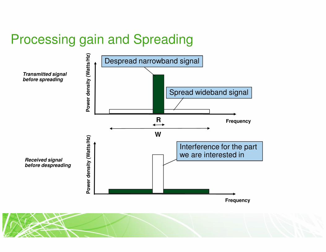
Processing gain and Spreading
Frequency
Despread narrowband signal
Spread wideband signal
W
R
Po
we
r d
en
sit
y (
Wa
tts
/Hz)
Po
we
r d
en
sit
y (
Wa
tts
/Hz)
Frequency
Transmitted signalbefore spreading
Received signalbefore despreading
Interference for the part we are interested in
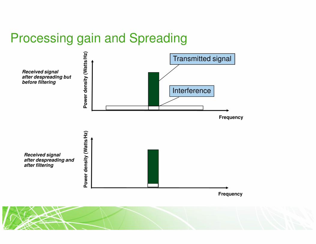
Processing gain and Spreading
Frequency
Po
we
r d
en
sit
y (
Wa
tts
/Hz)
Po
we
r d
en
sit
y (
Wa
tts
/Hz)
Frequency
Received signalafter despreading butbefore filtering
Received signalafter despreading andafter filtering
Transmitted signal
Interference

Processing gain and Spreading
• Spread spectrum systems reduce the effect of interference due to processing gain
• Processing gain is generally defined as follows:
– G[dB]=10*log10(W/R), where ’W’ is the chip rate and ’R’ is the user bit rate
• The number of users takes negative effect on the processing gain. The loss is defined as:
– Lp = 10*log10k, where ’k’ is the amount of users
• Processing gain when the processing loss is taken into account is
– Gtot=10*log10(W/kR)
• High bit rate means lower processing gain and higher power OR smaller coverage
• The processing gain is different for different services over 3G mobile network (voice, web browsing, videophone) due to different bit rates
– Thus, the coverage area and capacity might be different for different services depending on the radio network planning issues

Processing gain and Spreading
• Processing gain is what gives CDMA systems the robustness against
self-interference that is necessary in order to reuse the available 5
MHz carrier frequency over geographically close distances.
• Examples: Speech service with a bit rate of 12.2 kbps
– processing gain 10 log10(3.84e6/12.2e3) = 25 dB
– For speech service the required SINR is typically in the order of 5.0 dB, so
the required wideband signal-to-interference ratio (also called “carrier-to-
interference ratio, C/I ) is therefore “5.0 dB minus the processing” = -20.0
dB.
– In other words, the signal power can be 20 dB under the interference or
thermal noise power, and the WCDMA receiver can still detect the signal.
– Notice: in GSM, a good quality speech connection requires C/I = 9–12 dB.

Introduction to Wideband Code Division Multiple Access (WCDMA)
• Overview
• Codes in WCDMA
• QoS support
• Network Architecture
• Radio propagation and fading
• RAKE receiver
• Power Control in WCDMA
• Diversity
• Capacity and coverage

WCDMA System
• WCDMA is the most common radio interface for UMTS systems
• Wide bandwidth, 3.84 Mcps (Megachips per second)
– Maps to 5 MHz due to pulse shaping and small guard bands between the
carriers
• Users share the same 5 MHz frequency band and time
– UL and DL have separate 5 MHz frequency bands
• High bit rates
– With Release ’99 theoretically 2 Mbps both UL and DL
– 384 kbps highest implemented
• Fast power control (PC)
=> Reduces the impact of channel fading and minimizes the interference

WCDMA System
• Soft handover
– Improves coverage, decreases interference
• Robust and low complexity RAKE receiver
– Introduces multipath diversity
• Variable spreading factor
– Support for flexible bit rates
• Multiplexing of different services on a single physical connection
– Simultaneous support of services with different QoS requirements:• real-time
– E.g. voice, video telephony
• streaming
– streaming video and audio
• interactive
– web-browsing
• background
– e-mail download
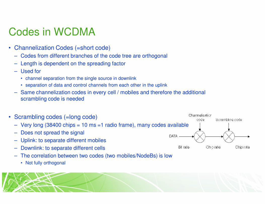
Codes in WCDMA
• Channelization Codes (=short code)
– Codes from different branches of the code tree are orthogonal
– Length is dependent on the spreading factor
– Used for
• channel separation from the single source in downlink
• separation of data and control channels from each other in the uplink
– Same channelization codes in every cell / mobiles and therefore the additional scrambling code is needed
• Scrambling codes (=long code)
– Very long (38400 chips = 10 ms =1 radio frame), many codes available
– Does not spread the signal
– Uplink: to separate different mobiles
– Downlink: to separate different cells
– The correlation between two codes (two mobiles/NodeBs) is low
• Not fully orthogonal

Codes in WCDMA
• For instance, the relation between downlink physical layer bit rates and codes
SpreadingFactor (SF)
Channelsymbol
rate(ksps)
Channelbit rate(kbps)
DPDCHchannel bitrate range
(kbps)
Maximum userdata rate with ½-
rate coding(approx.)
512 7.5 15 3–6 1–3 kbps256 15 30 12–24 6–12 kbps128 30 60 42–51 20–24 kbps64 60 120 90 45 kbps
32 120 240 210 105 kbps
16 240 480 432 215 kbps
8 480 960 912 456 kbps
4 960 1920 1872 936 kbps
4, with 3
parallel
codes
2880 5760 5616 2.3 Mbps
Half rate speech
Full rate speech
144 kbps
384 kbps
2 Mbps
Symbol_rate =
Chip_rate/SFBit_rate =
Symbol_rate*2
Control channel
(DPCCH) overheadUser bit rate with coding = Channel_bit_rate/2

QoS Support
• Key Factors:
– Simultaneous support of services with different QoS
requirements:
• up to 210 Transport Format Combinations, selectable individually
for every radio frame (10 ms)
• going towards IP core networks greatly increases the usage of
simultaneous applications requiring different quality, e.g. real time
vs. non-real time
– Optimized usage of different transport channels for
supporting different QoS

QoS support
Example:
DownlinkShared Channel
DownlinkDedicated Channels
USER 1
....
10 ms
USER 2 USER 3 USER 1 USER 1
USER 4
Data Rate
2 Mbps
Code 5
Code 4
Code 3
Code 2
Code 1USER 1
USER 2
USER 3
USER 4
USER 2
Time
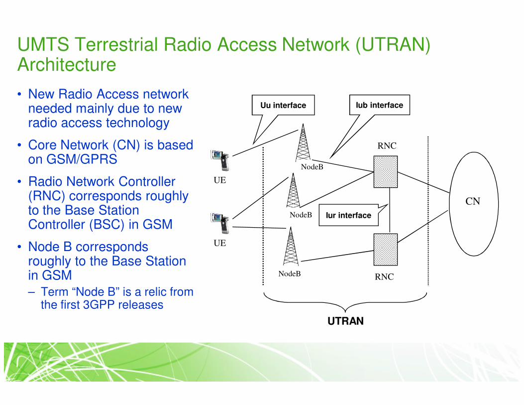
UMTS Terrestrial Radio Access Network (UTRAN) Architecture
• New Radio Access network needed mainly due to new radio access technology
• Core Network (CN) is based on GSM/GPRS
• Radio Network Controller (RNC) corresponds roughly to the Base Station Controller (BSC) in GSM
• Node B corresponds roughly to the Base Station in GSM
– Term “Node B” is a relic from the first 3GPP releases
RNC
NodeB
NodeB
NodeB
UE
CN
RNC
UE
Uu interface Iub interface
Iur interface
UTRAN

UMTS Terrestrial Radio Access Network (UTRAN) Architecture
• Radio network controller (RNC)
– Owns and controls the radio resources in its domain
– Radio resource management (RRM) tasks include e.g. the following
• Mapping of QoS Parameters into the air interface
• Air interface scheduling
• Handover control
• Outer loop power control
• Call Admission Control
• Setting of initial powers and SIR targets
• Radio resource reservation
• Code allocation
• Load Control

UMTS Terrestrial Radio Access Network (UTRAN) Architecture
• Node B
– Main function to convert the data flow between Uu and Iub interfaces
– Some RRM tasks:
• Measurements
• Inner loop power control

Radio propagation and fading
• A transmitted radio signal goes
through several changes while
traveling via air interface to the
receiver
– reflections, diffractions, phase
shifts and attenuation
• Due to length difference of the
signal paths, multipath
components of the signal arrive
at different times to the receiver
and can be combined either
destructively or constructively
– Depends on the phases of the
multipath components

Radio propagation and fading
• Example of the fast fading
channel of a function of time
• Opposite phases of two
random multipath components
arriving at the same time
cancel each other out
– Results in a fade
• Coherent phases are
combined constructively

RAKE receiver
• Every multipath component arriving at the receiver more than one chip
time (0.26 µs) apart can be distinguished by the RAKE receiver
– 0.26 µs corresponds to 78 m in path length difference
• RAKE assigns a “finger” to each received component (tap) and alters
their phases based on a channel estimate so that the components can
be combined constructively
Finger #1
Finger #2
Finger #3
Transmitted
symbol
Received
symbol at
each time
slot
Phase
modified using
the channel
estimate
Combined
symbol

Power Control in WCDMA
• The purpose of power control (PC) is to ensure that each user
receives and transmits just enough energy to have service but to
prevent:
– Blocking of distant users (near-far-effect)
– Exceeding reasonable interference levels
UE1UE2
UE3
UE1
UE2
UE3
UE1 UE2 UE3
Without PC received
power levels would
be unequal
With ideal PC
received power levels
are equal

Power Control in WCDMA
1. Open loop power control
• Only for the initial power setting of the MS
• Based on distance attenuation estimation from the downlink pilot signal
2. Inner loop transmitter power control (CL TPC) at a rate of 1500 Hz
• Mitigates fading processes (fast and slow fading)
• Tx power is adjusted up/down to reach SIR target
• Both in UL and DL
• Uses quality targets in MS / BS
3. Outer loop PC at the rate of 100 Hz
• Sets the quality target used by the inner loop PC
• Compensates the changes in the propagation conditions
• Adjusts the quality target
• Both in UL and DL

Power Control in WCDMA
• Inner loop power control in the uplink
– Outer loop PC (running in the radio network controller, RNC) defines SIR
target for the BS.
– If the measured SIR at BS is lower than the SIR-target, the MS is
commanded to increases its transmit power. Otherwise MS is commanded
to decrease its power
– Power control dynamics at the MS is 70 dB

Power Control in WCDMA
• Inner loop power control in downlink:
– Outer loop PC (running in the MS) defines SIR target for the MS
– If the measured SIR at the MS is lower than the SIR-target, the BS is
commanded to increases its transmit power for that MS. Otherwise, BS is
commanded to decrease its power.
– Power control rate 1500 Hz
– Power control dynamics is dependent on the service
– There’s no near-far problem in DL due to one-to-many scenario. However, it
is desirable to provide a marginal amount of additional power to mobile
stations at the cell edge, as they suffer from increased other-cell
interference.

Power Control in WCDMA
• Example of inner loop power
control behavior:
• With higher velocities channel
fading is more rapid and 1500 Hz
power control may not be sufficient

Power Control in WCDMA
• Inner loop power control tries to keep the received SIR as close to the target
SIR as possible.
• However, the constant SIR alone does not actually guarantee the required
frame error rate (FER) which can be considered as the quality criteria of the
link/service.
– There’s no unique SIR that automatically gives a certain FER
– FER is a function of SIR, but also depends on mobility and propagation environment.
• Therefore, the frame reliability information has to be delivered to outer loop
control, which can tune the SIR target if necessary.

Diversity
• Transmitting on a single path only can lead to serious performance
degradation due to fading
• As fading is independent between different times and spaces it is reasonable
to use the available diversity of them to decrease the probability of a deep
fade
– The more there are paths to choose from, the less likely it is that all of them have a poor energy level
• There exists different types of diversity which can be used to improve the
quality, e.g.:
– Multipath
• RAKE receiver exploits taps arriving at different times
– Macro
• Different Node Bs send the same information
– Site Selection Transmit Diversity (SSTD)
• Maintain a list of available base stations and choose the best one, from which the transmission
is received and tell the others not to transmit

Diversity
– Time
• Same information is transmitted in different times
– Receive antenna
• Transmission is received with multiple antennas
• Power gain and diversity gain
– Transmit antenna
• Transmission is sent with multiple antennas

WCDMA Handovers
• WCDMA handovers can be categorized into three different types
• Intra-frequency handover
– WCDMA handover within the same frequency and system. Soft, softer and
hard handover supported
• Inter-frequency handover
– Handover between different frequencies (carriers) but within the same
system
– E.g. from one WCDMA operator to another
– Only hard handover supported
• Inter-system handover
– Handover between WCDMA and another system, e.g. from WCDMA to
GSM
– Only hard handover supported

WCDMA Handovers
• Soft handover
– Handover between different Node Bs
– Several Node Bs transmit the same signal to the UE which combines the transmissions
• Advantages: lower Tx power needed for each Node B and UE
– lower interference, battery saving for UE
• Disadvantage: resources (code, power) need to be reserved for the UE in each Node B
– Excess soft handovers limit the capacity
– No interruption in data transmission
– Needs RNC duplicating frame transmissions to two Node Bs

WCDMA Handovers
• Softer handover
– Handover between two sectors of the
same Node B
• Special case of a soft handover
• No need for duplicate frames
• Hard handover
– The source is released first and then new
one is added
– Short interruption in data flow

WCDMA Handovers
• Some terminology
– Active set (AS), represents the Node Bs to which the UE is in soft handover
– Neighbor set (NS), represents the links that UE monitors but which are not
already in active set
Received
signal
strength
BS1
BS2
Threshold_1
Triggering time_1
Threshold_2
Triggering time_2
BS2 from the NS reaches
the threshold to be added
to the ASBS2 is still after the
triggering time above
threshold and thus added
to the AS
BS1 from the AS reaches
the threshold to be
dropped from the AS
BS1 dropped from the AS

Capacity and coverage
• In WCDMA coverage and capacity are tight together:
– When the load increases, the interference levels increases, too, and
therefore also increased transmit powers are needed in order to keep
constant quality.
– Due to finite power resources, the more users Node B serves the less
power it has for each UE � coverage will decrease
• This leads to cell breathing: the coverage area changes as the load of
the cell changes.• Therefore, the coverage and
the capacity have to be
planned simultaneously
• Radio resource management
(RRM) is needed in WCDMA to
effectively control cell
breathing.

Capacity and coverage
• Received power of one user as a function of users per cell
• Due to finite maximum Tx power of the UE coverage is usually limited by the uplink
• Node B does not have this problem
– There is enough Tx power to transmit very far to a single user if necessary
– However, downlink Tx power is divided between all users and thus capacity is limited by the downlink

WCDMA evolution
•High Speed Downlink Packet Access (HSDPA)
•High Speed Uplink Packet Access (HSUPA)
•Advanced receivers with HSDPA
•Advanced HSDPA scheduling
•Femto cells with HSDPA

High Speed Downlink Packet Access (HSDPA)
• The High Speed Downlink Packet Access (HSDPA) concept was
added to Release 5 to support higher downlink data rates
• It is mainly intended for non-real time traffic, but can also be used for
traffic with tighter delay requirements.
• Peak data rates up to 10 Mbit/s (theoretical data rate 14.4 Mbit/s)
• Reduced retransmission delays
• Improved QoS control (Node B based packet scheduler)
• Spectrally and code efficient solution
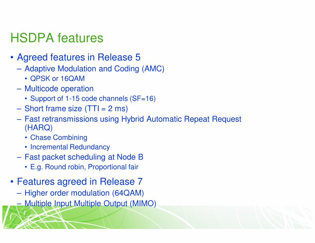
HSDPA features
• Agreed features in Release 5– Adaptive Modulation and Coding (AMC)
• QPSK or 16QAM
– Multicode operation
• Support of 1-15 code channels (SF=16)
– Short frame size (TTI = 2 ms)
– Fast retransmissions using Hybrid Automatic Repeat Request (HARQ)
• Chase Combining
• Incremental Redundancy
– Fast packet scheduling at Node B
• E.g. Round robin, Proportional fair
• Features agreed in Release 7– Higher order modulation (64QAM)
– Multiple Input Multiple Output (MIMO)

HSDPA - general principle
• Fast scheduling is done directly in Node-B based on feedback information from UE and knowledge of current traffic state.
Channel quality(CQI, Ack/Nack, TPC)
Data
Users may be time and/or code multiplexedPacket data scheduling (short TTI)
New base station functions
• HARQ retransmissions
• Modulation/coding selection
• Packet data scheduling (short TTI)
UE
0 20 40 60 80 100 120 140 160-2
02468
10121416
Time [number of TTIs]
QPSK1/4
QPSK2/4
QPSK3/4
16QAM2/4
16QAM3/4
Inst
anta
neo
us
EsN
o [d
B]

HSDPA functionality
• Scheduling responsibility has been moved from RNC to Node B
• Due to this and the short TTI length (2 ms) the scheduling is dynamic
and fast
• Support for several parallel transmissions
– When packet A is sent it starts to wait for an acknowledgement from the
receiver, during which other packets can be sent via a parallel SAW (stop-
and-wait) channels
Pkt A
Pkt B
Pkt C
Pkt D
Pkt E
Pkt F
Ack B

HSDPA functionality• UE informs the Node B regularly of its channel quality by CQI messages
(Channel Quality Indicator)

HSDPA functionality
• Node B can use channel state information for several purposes
– In transport format (TFRC) selection
• Modulation and coding scheme
– Scheduling decisions
• Non-blind scheduling algorithms can be utilized
– HS-SCCH power control

HSDPA channels
• User data is sent on High Speed Downlink Shared Channel (HS-
DSCH)
• Control information is sent on High Speed Common Control Channel
(HS-SCCH)
• HS-SCCH is sent two slot before HS-DSCH to inform the scheduled
UE of the transport format of the incoming transmission on HS-DSCH

High Speed Uplink Packet Access (HSUPA)
• Peak data rates increased to significantly higher than 2 Mbps; Theoretically reaching 5.8 Mbps
• Packet data throughput increased, though not as high throughput as with HSDPA
• Reduced delay from retransmissions.
• Solutions
– Layer1 hybrid ARQ
– NodeB based scheduling for uplink
– Frame sizes 2ms & 10 ms
• Schedule in 3GPP
– Part of Release 6
– First specifications version completed 12/04
– In 3GPP specs with the name Enhanced uplink DCH (E-DCH)

5 codes QPSK
# of codes Modulation
5 codes 16-QAM
10 codes 16-QAM
15 codes 16-QAM
15 codes 16-QAM
1.8 Mbps
Maxdata rate
3.6 Mbps
7.2 Mbps
10.1 Mbps
14.4 Mbps
2 x SF42 ms10 ms
# of codes TTI
2 x SF2 10 ms
2 x SF2 2 ms
2 x SF2 +2 x SF4
2 ms
1.46 Mbps
Maxdata rate
2.0 Mbps
2.9 Mbps
5.76 Mbps
Downlink HSDPA
• Theoretical up to 14.4 Mbps
• Initial capability 1.8 – 3.6 Mbps
Uplink HSUPA
• Theoretical up to 5.76 Mbps
• Initial capability 1.46 Mbps
HSPA Peak Data Rates

Performance of advanced HSDPA features

Advanced receivers with HSDPA
• UE receiver experiences significant interference from different sources
– In a reflective environment the signal interferes itself
– Neigboring base station signals interfere each other
– One solution to decrease mainly own base station signal interference is to
use an equalizer before despreading
Own cell interference
Other cell interference
Own signal

Advanced receivers with HSDPA
• In a frequency-selective channel there is a significant amount of
interfering multipaths
• Linear Minimum Mean Squared Error (LMMSE) equalizer can be used
to make an estimate of the original transmitted chip sequence before
despreading
– The interfering multipath components are removed
– The channel becomes flat again

Advanced receivers with HSDPA
• LMMSE equalizer (Equ in the
figure) offers a very good
performance for the user
especially near the base station
• Using antenna diversity (1x2) the
throughput can be doubled
compared to a single antenna
• Both techniques increase the
cost of a mobile unit

Advanced HSDPA scheduling
• Node B has a limited amount of scheduling opportunities
• The amount of data transmitted by the network must be maximized
whilst offering the best possible quality of service to all users
– The scheduling can be improved by an advanced algorithm

Advanced HSDPA scheduling
• An improved scheduling
algorithm (Proportional Fair,
PF) offers significant gain over
a conventional algorithm
(Round Robin, RR)
• PF has a very good price-
quality ratio
– User equipment needs no
changes
– Node B’s need only minor
changes

Femtocells
• More and more consumers want to use their mobile devices at home,
even when there’s a fixed line available
– Providing full or even adequate mobile residential coverage is a significant
challenge for operators
– Mobile operators need to seize residential minutes from fixed line providers,
and compete with fixed and emerging VoIP and WiFi services
=> There is trend in discussing very small indoor, home and campus NodeB
layouts
• Femtocells are cellular access points (for limited access group) that
connect to a mobile operator’s network using residential DSL or cable
broadband connections
• Femtocells enable capacity equivalent to a full 3G network sector at
very low transmit powers, dramatically increasing battery life of
existing phones, without needing to introduce WiFi enabled handsets

Femtocells• The study considers the system performance of an HSDPA network consisting of macro cells and
very low transmit power (femto) cells
• The impact of using 64QAM in addition to QPSK and 16QAM in order to benefit from the high SINR is studied
• The network performance is investigated with different portions of users created in the buildings (0-100%)

Femtocells
• Femtocells provide maximum of 15-
17 % gain to network throughput
already without dedicated indoor
users
• The gain is visible with high load in
the network and comes directly from
the increased number of access
points in the network
• Average load of a cell is decreased
and users can be scheduled more
often
SchemeOffered load
Medium High Congested
Rake 1x1 3 % 8 % 15 %
Rake 1x2 -1 % 19 % 13 %
Equ 1x1 -2 % 18 % 15 %
Equ 1x2 -1 % 3 % 17 %
Table: Network throughput gain of
femto cells to macro users

Femtocells
• When the amount of dedicated indoor
users increase, the gain of femto cells
explodes
• Gain is in the range of hundreds of
percents even with small portion of
indoor users