3g mobile communication networks - asad · pdf file3g mobile communication networks ..... 6...
TRANSCRIPT

3G Mobile Communication Networks
EXPLORE SUMMER 2006
Submitted By
GROUP 04
Nabeel ur Rehman 2003-NUST-BICSE-090 Asad Asif 2004-NUST-BICSE-116
Junaid Iqbal 2003-NUST-BICSE-076
Submitted To
Mr. Aamir Jelani
Explore Summer 2006 3G Mobile Communication Networks
2
Table of Contents LISTS OF FIGURES ................................................................................................................................... 3 LIST OF TABLES ........................................................................................................................................ 4 ABSTRACT .................................................................................................................................................. 5 3G MOBILE COMMUNICATION NETWORKS ................................................................................... 6
BACK GROUND ........................................................................................................................................... 6 EARLY STAGES: 1G TO 3G ......................................................................................................................... 6 FIRST GENERATION (1G): ANALOG CELLULAR .......................................................................................... 6 SECOND GENERATION (2G): MULTIPLE DIGITAL SYSTEMS ........................................................................ 6
IMT–2000.............................................................................................................................................. 7 CDMA2000 ............................................................................................................................................. 10
An Overview ........................................................................................................................................ 10 Table 01: Technical Summary for CDMA2000 ................................................................................... 10
BASIC TERMINOLOGIES ............................................................................................................................ 11 Forward and Reverse Link .................................................................................................................. 11 Channel Access Duplex Methods ........................................................................................................ 11 Summary of Channel Access Methods ................................................................................................ 14 Summary of Channel Access Methods ................................................................................................ 15
CHANNELIZATION IN CDMA2000 ............................................................................................................ 15 CHANNELIZATION IN CDMA2000 ............................................................................................................ 16
Introduction ........................................................................................................................................ 16 Walsh Codes ....................................................................................................................................... 16 Forward Link ...................................................................................................................................... 18 Channelization .................................................................................................................................... 19 Reverse Link ........................................................................................................................................ 24
SPECIAL INTEREST AREAS ................................................................................................................. 26 INTERESTED AREAS .................................................................................................................................. 26 CONTACTED INSTITUTION ........................................................................................................................ 26 CONTACTED PERSONNEL .......................................................................................................................... 26
RESEARCH UNDERGOING IN SPECIFIED AREA ........................................................................... 26 OPTICAL FIBER COMMUNICATION USING CDMA ..................................................................................... 26 DIFFERENCE BETWEEN WCDMA WITH CDMA2000 ............................................................................... 27
REFERENCES ........................................................................................................................................... 28 REFERENCE RESEARCH PAPERS ................................................................................................................ 28 REFERENCE URLS .................................................................................................................................... 28 REFERENCE BOOKS .................................................................................................................................. 29 WORKSHOPS AND SEMINARS .................................................................................................................... 29

Explore Summer 2006 3G Mobile Communication Networks
3
Lists of Figures
S.No. Name of Figure Page Number 01 Figure 1 6 02 Figure 2 7 03 Figure 3 9 04 Figure 4 10 05 Figure 5 11 06 Figure 6 12 07 Figure 7 13 08 Figure 8 16 09 Figure 9 19 10 Figure 10 20 11 Figure 11 20 12 Figure 12 21 13 Figure 13 23

Explore Summer 2006 3G Mobile Communication Networks
4
List of Tables
S.No. Name of Table Page Number 01 Table 1 8 02

Explore Summer 2006 3G Mobile Communication Networks
5
Abstract Over the past decade, wireless communications has seen an exponential growth and will certainly continue to witness spectacular developments due to the emergence of new interactive multimedia applications and highly integrated systems driven by the rapid growth in information services and microelectronic devices. So far, most of the current mobile systems are mainly targeted to voice communications with low transmission rates. In the near future, however, broadband data access at high transmission rates will be needed to provide users packet-based connectivity to a plethora of services. It is also almost certain that the neXt Generation (XG) wireless systems will consist of complementary systems with a set of different standards and technologies along with different requirements and complementary capabilities that will offer users ubiquitous wireless connectivity between mobile and desktop computers, machines, game systems, cellular phones, consumer electronic products, and other hand-held devices. A key requirement in future wireless system is their ability to provide broadband connectivity with end-to-end Quality of Service (QoS), a high network capacity, and throughput at a low cost. To support the above services, a host of new issues and problems have to be addressed. This talk will discuss the challenges facing the 3G communication networks and at some of the important issues pertaining to the evolution of mobile communication networks from GSM (Global System for Mobile Communications) to GPRS (General Packet Radio Service) to 3G (Third Generation) and to CDMA and WCDMA. And also describe some of the leading enabling technologies and comparison of CDMA2000 and WCDMA

Explore Summer 2006 3G Mobile Communication Networks
6
3G Mobile Communication Networks
Back Ground Third generation (3G) is the generic term used for the next generation of mobile communications systems. These have been created to support the effective delivery of a range of multimedia services. In addition, they provide more efficient systems for the over-the-air transmission of existing services, such as voice, text and data that are available today.
Early Stages: 1G to 3G Electromagnetic waves were first discovered as a communications medium at the end of the 19th century. The first systems offering mobile telephone service (car phone) were introduced in the late 1940s in the United States and in the early 1950s in Europe. Those early single cell systems were severely constrained by restricted mobility, low capacity, limited service, and poor speech quality. The equipment was heavy, bulky, expensive, and susceptible to interference. Because of those limitations, less than one million subscribers were registered worldwide by the early 1980s.
First Generation (1G): Analog Cellular The introduction of cellular systems in the late 1970s and early 1980s represented a quantum leap in mobile communication (especially in capacity and mobility). Semiconductor technology and microprocessors made smaller, lighter weight and more sophisticated mobile systems a practical reality for many more users. These 1G cellular systems still transmit only analog voice information. The most prominent 1G systems are Advanced Mobile Phone System (AMPS), Nordic Mobile Telephone (NMT), and Total Access Communication System (TACS). With the 1G introduction, the mobile market showed annual growth rates of 30 to 50 percent, rising to nearly 20 million subscribers by 1990.
Second Generation (2G): Multiple Digital Systems The development of 2G cellular systems was driven by the need to improve transmission quality, system capacity, and coverage. Further advances in semiconductor technology and microwave devices brought digital transmission to mobile communications. Speech transmission still dominates the airways, but the demands for fax, short message, and data transmissions are growing rapidly. Supplementary services such as fraud prevention and encrypting of user data have become standard features that are comparable to those in fixed networks. 2G cellular systems include GSM, Digital AMPS (D-AMPS), code division multiple access (CDMA), and Personal Digital Communication (PDC). Today, multiple 1G and 2G standards are used in worldwide mobile communications. Different standards serve different applications with different levels of mobility, capability, and service area (paging systems, cordless telephone, wireless local loop, private mobile

Explore Summer 2006 3G Mobile Communication Networks
7
radio, cellular systems, and mobile satellite systems). Many standards are used only in one country or region, and most are incompatible. GSM is the most successful family of cellular standards (GSM900, GSM–railway [GSM–R], GSM1800, GSM1900, and GSM400), supporting some 250 million of the world’s 450 million cellular subscribers with international roaming in approximately 140 countries and 400 networks. 2G to 3G: GSM Evolution Phase 1 of the standardization of GSM900 was completed by the European Telecommunications Standards Institute (ETSI) in 1990 and included all necessary definitions for the GSM network operations. Several tele-services and bearer services have been defined (including data transmission up to 9.6 kbps), but only some very basic supplementary services were offered. As a result, GSM standards were enhanced in Phase 2 (1995) to incorporate a large variety of supplementary services that were comparable to digital fixed network integrated services digital network (ISDN) standards. In 1996, ETSI decided to further enhance GSM in annual Phase 2+ releases that incorporate 3G capabilities. GSM Phase 2+ releases have introduced important 3G features such as intelligent network (IN) services with customized application for mobile enhanced logic (CAMEL), enhanced speech compression/decompression (CODEC), enhanced full rate (EFR), and adaptive multi-rate (AMR), high–data rate services and new transmission principles with high-speed circuit-switched data (HSCSD), general packet radio service (GPRS), and enhanced data rates for GSM evolution (EDGE). UMTS is a 3G GSM successor standard that is downward-compatible with GSM, using the GSM Phase 2+ enhanced core network.
IMT–2000 The main characteristics of 3G systems, known collectively as IMT–2000, are a single family of compatible standards that have the following characteristics:
1. Used worldwide 2. Used for all mobile applications 3. Support both packet-switched (PS) and circuit-switched (CS) data transmission 4. Offer high data rates up to 2 Mbps (depending on mobility/velocity) 5. Offer high spectrum efficiency

Explore Summer 2006 3G Mobile Communication Networks
8
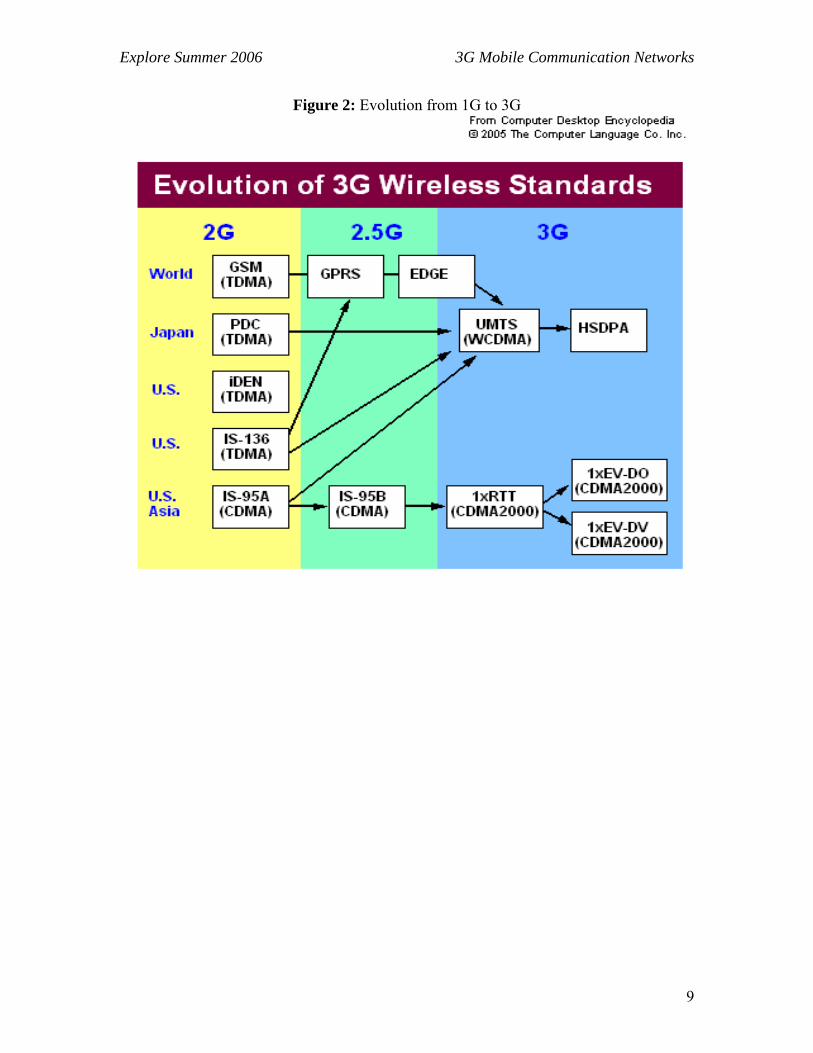
Figure 1: Multiple Standards for Different Applications and Countries IMT–2000 is a set of requirements defined by the International Telecommunications Union (ITU). As previously mentioned, IMT stands for International Mobile Telecommunications, and “2000” represents both the scheduled year for initial trial systems and the frequency range of 2000 MHz (WARC’92: 1885–2025 MHz and 2110–2200 MHz). All 3G standards have been developed by regional standards developing organizations (SDOs). In total, proposals for 17 different IMT–2000 standards were submitted by regional SDOs to ITU in 1998—11 proposals for terrestrial systems and 6 for mobile satellite systems (MSSs). Evaluation of the proposals was completed at the end of 1998, and negotiations to build a consensus among differing views were completed in mid 1999. All 17 proposals have been accepted by ITU as IMT–2000 standards. The specification for the Radio Transmission Technology (RTT) was released at the end of 1999. The most important IMT–2000 proposals are the UMTS (W-CDMA) as the successor to GSM, CDMA2000 as the interim standard ’95 (IS–95) successor, and time division–synchronous CDMA (TD–SCDMA) (universal wireless communication–136 [UWC–136]/EDGE) as TDMA–based enhancements to D–AMPS/GSM—all of which are leading previous standards toward the ultimate goal of IMT–2000. The figure 2 show the shift from 1G to 3G
Explore Summer 2006 3G Mobile Communication Networks
9
Figure 2: Evolution from 1G to 3G

Explore Summer 2006 3G Mobile Communication Networks
10
CDMA2000
An Overview Cdma2000 specification was developed by the Third Generation Partnership Project 2 (3GPP2), a partnership consisting of five telecommunications standards bodies: ARIB and TTC in Japan, CWTS in China, TTA in Korea and TIA in North America. Cdma2000 has already been implemented to several networks as an evolutionary step from CDMAOne as cdma2000 provides full backward compatibility with IS-95B. Cdma2000 is not constrained to only the IMT-2000 band, but operators can also overlay acdma2000 1x system, which supports 144 kbps now and data rates up to 307 kbps in the future, on top of their existing CDMAOne network. The evolution of cdma2000 1x is labeled cdma2000 1xEV. 1xEV will be implemented in steps: 1xEV-DO and 1xEV-DV. 1xEV-DO stands for "1x Evolution Data Only". 1xEV-DV stands for "1x Evolution Data and Voice". Both 1xEV cdma2000 evolution steps will use a standard 1.25 MHz carrier. 1xEV-DO probably will be available for cdma2000 operators during 2002 and 1xEV-DV solutions will be available approximately late 2003 or early 2004. Cdma2000 1x EV-DO and cdma2000 3x are an ITU-approved, IMT-2000 (3G) standards. Cdma2000 3x is part of what the ITU has termed IMT-2000 CDMA MC (Multi Carrier). It uses less that 5 MHz spectrum (3x 1.25 MHz channels) to give speeds of over 2 Mbps. Cdma2000 1x with lower data speed is considered to be a 2.5G technology.
Table 01: Technical Summary for CDMA2000 Frequency band Any existing band. Minimum frequency band required 1x: 2x1.25MHz, 3x: 2x3.75 Chip rate 1x: 1.2288, 3x: 3.6864 Mcps Maximum user data rate: 1x: 144 kbps now, 307 kbps in the future
1xEV-DO: max 384 kbps - 2.4 Mbps, 1xEV-DV: 4.8 Mbps.
Frame length 5ms, 10ms or 20ms Power control rate 800 Hz Spreading factors 4 ... 256 UL

Explore Summer 2006 3G Mobile Communication Networks
11
Mobile Station
Base Station
Forward link
Reverse link
Figure 3: Forward and Reverse Links
Basic Terminologies Some of the Concepts which should e considered in order to understand the further details of the of CDMA2000 and WCDMA are discussed in the following section
Forward and Reverse Link The transmission from a base station to a mobile phone is considered as the forward link. The reverse link is from the mobile phone to the base station. Reverse and forward links are shown in figure 3.
Channel Access Duplex Methods Channel access methods are used in point to multipoint networks such as cellular networks for dividing forward and reverse communication channels on the same physical communications medium, they are known as duplexing methods, such as:
Time Division Duplex
Time division duplex (TDD) is the application of time-division multiple access to separate outward and return signals. Time division duplex has a strong advantage in the case where the asymmetry of the uplink and downlink data speed is variable. As the amount of uplink data increases, more bandwidth can be allocated to that and as it shrinks it can be taken away. Another advantage is that the uplink and downlink radio paths are likely to be very similar in the case of a slow moving system. This means that techniques such as beam forming work well with TDD systems.
Explore Summer 2006 3G Mobile Communication Networks
12
Mobile Station
Base Station
Forward link (F1)
Reverse link (F2)
(a)
Transmitter
Receiver
BPF: Band Pass Filter
BPF
BPF
Transmitter
Receiver
BPF
BPF
F1
F2 F1
F2
Mobile Station Base Station
(b)
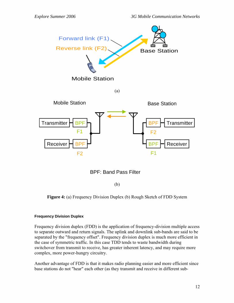
Figure 4: (a) Frequency Division Duplex (b) Rough Sketch of FDD System
Frequency Division Duplex
Frequency division duplex (FDD) is the application of frequency-division multiple access to separate outward and return signals. The uplink and downlink sub-bands are said to be separated by the "frequency offset". Frequency division duplex is much more efficient in the case of symmetric traffic. In this case TDD tends to waste bandwidth during switchover from transmit to receive, has greater inherent latency, and may require more complex, more power-hungry circuitry. Another advantage of FDD is that it makes radio planning easier and more efficient since base stations do not "hear" each other (as they transmit and receive in different sub-

Explore Summer 2006 3G Mobile Communication Networks
13
Mobile Station
Base Station
Forward link (F1)
Reverse link (F1)
(a)
Transmitter
Receiver
BPF
Transmitter
Receiver
BPFF1 F1
Mobile Station Base Station
Synchronous Switches
(b)
Figure 5: (a) Time Division Duplex (b) Rough Sketch of TDD System
bands) and therefore will normally not interfere each other. With TDD systems, care must be taken to keep guard bands between neighboring base stations (which decreases spectral efficiency) or to synchronize base stations so they will transmit and receive at the same time (which increases network complexity and therefore cost, and reduces bandwidth allocation flexibility as all base stations and sectors will be forced to use the same uplink/downlink ratio)

Explore Summer 2006 3G Mobile Communication Networks
14
Figure 6: (a) Message Signal, (b) Direct Spread Sequence, (c) Frequency Spread Sequence
Spread Spectrum Techniques
There are major two type of spread spectrum techniques. Direct Sequence Spread spectrum and Frequency hoping spread Spectrum. CDMA is a multiple-access scheme based on spread-spectrum communication techniques. It spreads the message signal to a relatively wide bandwidth by using a unique code that reduces interference, enhances system processing, and differentiates users. CDMA does not require frequency or time-division for multiple access; thus, it improves the capacity of the communication system. Spread-spectrum communications is a secondary modulation technique. In a typical spread-spectrum communication system, the message signal is first modulated by traditional amplitude, frequency, or phase techniques. A pseudorandom noise (PN) signal is then applied to spread the modulated waveform over a relatively wide bandwidth. The PN signal can amplitude modulate the message waveform to generate direct-sequence spreading, or it can shift the carrier frequency of the message signal to produce frequency-hopped spreading, as shown in Figure 3. The direct-sequence spread-spectrum signal is generated by multiplying the message signal d(t) by a pseudorandom noise signal pn (t):
g(t) = pn(t)d(t)

Explore Summer 2006 3G Mobile Communication Networks
15
FDMA
TDMA
CDMA
time
time
time
pow
er
pow
er
pow
er
frequency
frequency
frequency
Figure 7: (From Right to Left) CDMA, TDMA, and FDMA
Summary of Channel Access Methods

Explore Summer 2006 3G Mobile Communication Networks
16
Channelization in CDMA2000
Introduction CDMA is a scheme by which multiple users are assigned radio resources using DS-SS techniques. Although all users are transmitting in the same RF band, individual users are separated from each other via the use of orthogonal codes. The North American CDMA standard, or IS-95, specifies that each user conveys base band information at 9.6 Kbps (Rate Set 1), which is the rate of the vocoder output. The rate of the final spread signal is 1.2288 Mcps, resulting in an RF bandwidth of approximately 1.25 MHz. There can be many 1.25-MHz signals present in the same RF band. To a large degree, the performance of a CDMA system is interference-limited. This means that the capacity and quality of the system are limited by the amount of interference power present in the band. Capacity is defined as the total number of simultaneous users the system can support, and quality is defined as the perceived condition of a radio link assigned to a particular user; this perceived link quality is directly related to the probability of bit error, or bit error rate (BER). This chapter presents those characteristics of a CDMA system that need to be optimized in order to reduce interference and increase quality. The IS-95 CDMA and CDMA2000 system is unique in that its forward and reverse links have different link structures. This is necessary to accommodate the requirements of a land-mobile communication system. The forward link consists of four types of logical channels: pilot, sync, paging, and traffic channels. There is one pilot channel, one sync channel, up to seven paging channels, and several traffic channels. Each of these forward-link channels is first spread orthogonally by its Walsh function, and then it is spread by a quadrature pair of short PN sequences. All channels are added together to form the composite SS signal to be transmitted on the forward link. The reverse link consists of two types of logical channels: access and traffic channels. Each of these reverse-link channels is spread orthogonally by a unique long PN sequence; hence, each channel is identified using the distinct long PN code. The reason that a pilot channel is not used on the reverse link is that it is impractical for each mobile to broadcast its own pilot sequence.
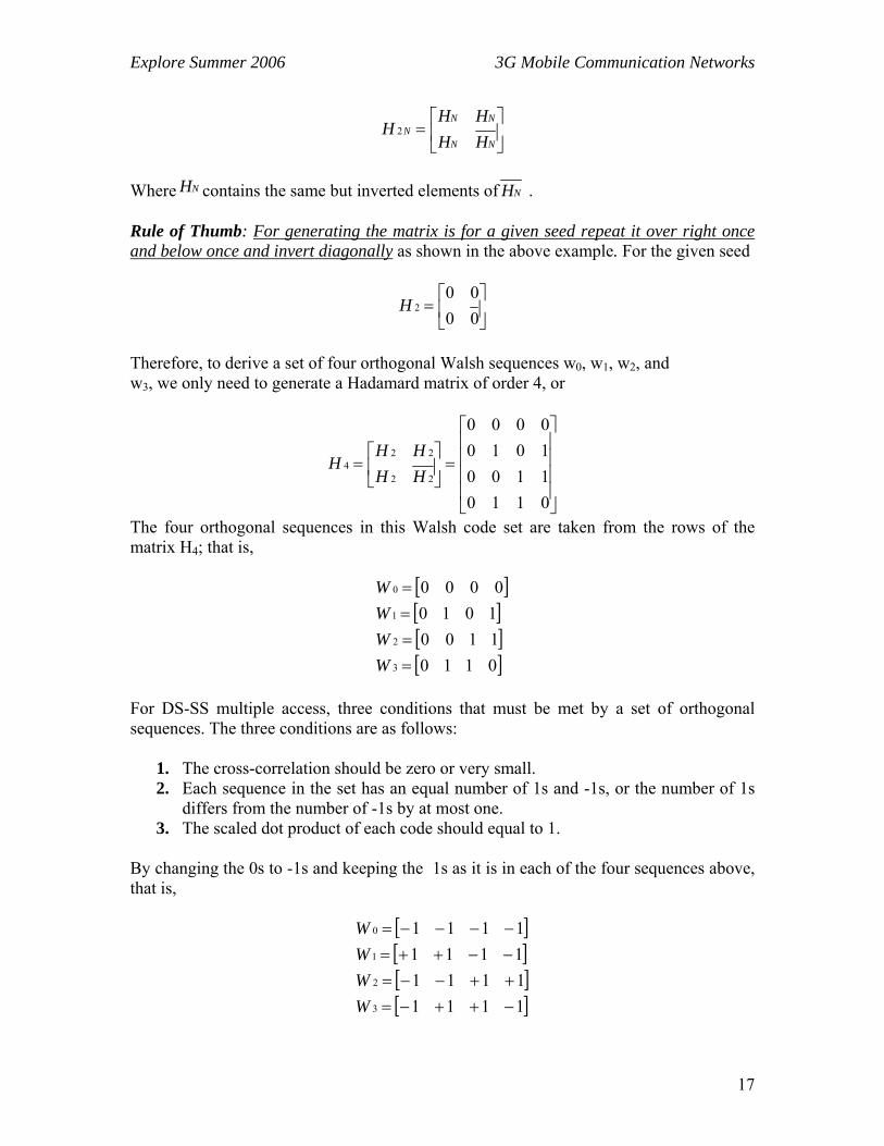
Walsh Codes In order to avoid mutual interference on the forward link, Walsh codes are used to separate individual users while they simultaneously occupy the same RF band. Walsh codes as used in IS-95 are a set of 64 binary orthogonal sequences. These sequences are orthogonal to each other, and they are generated by using the Hadamard matrix. Recursion is used to generate higher order matrices from lower order ones; that is,
Explore Summer 2006 3G Mobile Communication Networks
17
⎥⎦
⎤⎢⎣
⎡=
NN
NNN
HHHH
H 2
Where NH contains the same but inverted elements of NH . Rule of Thumb: For generating the matrix is for a given seed repeat it over right once and below once and invert diagonally as shown in the above example. For the given seed
⎥⎦
⎤⎢⎣
⎡=
0000
2H
Therefore, to derive a set of four orthogonal Walsh sequences w0, w1, w2, and w3, we only need to generate a Hadamard matrix of order 4, or
⎥⎥⎥⎥
⎦
⎤
⎢⎢⎢⎢
⎣
⎡
=⎥⎦
⎤⎢⎣
⎡=
0110110010100000
22
224
HHHH
H
The four orthogonal sequences in this Walsh code set are taken from the rows of the matrix H4; that is,
[ ][ ][ ][ ]0110
110010100000
3
2
1
0
====
WWWW
For DS-SS multiple access, three conditions that must be met by a set of orthogonal sequences. The three conditions are as follows:
1. The cross-correlation should be zero or very small. 2. Each sequence in the set has an equal number of 1s and -1s, or the number of 1s
differs from the number of -1s by at most one. 3. The scaled dot product of each code should equal to 1.
By changing the 0s to -1s and keeping the 1s as it is in each of the four sequences above, that is,
[ ][ ][ ][ ]1111
111111111111
3
2
1
0
−++−=++−−=−−++=−−−−=
WWWW

Explore Summer 2006 3G Mobile Communication Networks
18
Figure 8: 64 by 64 Hadamard Matrix for CDMA2000 Forward Link
In general, the 0th Walsh sequence consists of all -1s and thus cannot be used for channelization. In the IS-95 CDMA system, w0 is not used to transmit any Base band information.
Forward Link The structure of a Hadamard matrix and generation of Walsh codes is described in the last section. The IS-95 CDMA system uses a 64 by 64 Hadamard matrix to generate 64 Walsh functions that are orthogonal to each other, and each of the logic channels on the forward link is identified by its assigned Walsh function. This is shown in figure 07

Explore Summer 2006 3G Mobile Communication Networks
19
Channelization Channelization is done in following steps
• Generate Walsh Codes • Generate Codes for each message • Transmitted Signal • Retrieval of message
Suppose that there are three different users, and each user wishes to send a separate message. The separate messages are:
[ ][ ][ ]111
111111
2
1
0
++−=−++=+−+=
MMM
There respective codes are as follows:
[ ][ ][ ][ ]1111
111111111111
3
2
1
0
−++−=++−−=−−++=−−−−=
WWWW
The signal to be transmitted is calculated to be m (t) * w (t). This is shown below: M1 (t) = +1 -1 +1 M1 (t) = +1 +1 +1 +1 -1 -1 -1 -1 +1 +1 +1 +1 M1 (t) = -1 +1 -1 +1 -1 +1 -1 +1 -1 +1 -1 +1 M1 (t) * W1 (t) = -1 +1 -1 +1 +1 -1 +1 -1 -1 +1 -1 +1 Similarly for the M2 (t) and M3 (t) M2 (t) * W2 (t) = -1 -1 +1 +1 -1 -1 +1 +1 +1 +1 -1 -1 M3 (t) * W3 (t) = +1 -1 -1 +1 -1 +1 +1 -1 -1 +1 +1 -1 The spread-spectrum signals for all three messages, m1(t)w1(t), m2(t)w2(t), and m3(t)w3(t), are combined to form a composite signal C(t); that is,
C (t) = M1 (t) * W1 (t) + M2 (t) * W2 (t) + M3 (t) * W3 (t) The resulting C (t) is C (t) = -1 -1 -1 +3 -1 -1 +3 -1 -1 +3 -1 -1

Explore Summer 2006 3G Mobile Communication Networks
20
C(t) is the composite signal that is transmitted in the single RF band. If there are negligible errors during the transmission process, the receiver intercepts C (t). In order to separate out the original messages M1 (t), M2 (t), and M3 (t) from the composite signal C(t), the receiver multiplies C (t) by the assigned Walsh code for each message:

Explore Summer 2006 3G Mobile Communication Networks
21
Figure 9: Pilot Channel
Pilot Channel
The pilot channel is identified by the Walsh function 0 (w0). The channel itself contains no base band information. The base band sequence is a stream of 0s that are spread by Walsh function 0, which is also a sequence of all 0s. The resulting sequence (still all 0s) is then spread, or multiplied, by a pair of quadrature PN sequences. Therefore, the pilot channel is effectively the PN sequence itself (see Figure 8). The PN sequence with a specified offset uniquely identifies the particular sector that is transmitting the pilot signal. Note that both Walsh function 0 and the PN sequence are running at a rate of 1.2288 Mcps (Mega-Chips per second). After PN spreading, base band filters are used to shape the digital pulses. These filters effectively low pass filter the digital pulse stream and control the base band spectrum of the signal. This way, the signal bandwidth may have a sharper roll-off near the band edge. The pilot channel is transmitted continuously by the base station sector. The pilot channel provides the mobile with timing and phase reference. The mobile’s measurement of the signal-to-noise ratio (i.e., Ec /I0) of the pilot channel also gives an indication of which is the strongest serving sector of that mobile.
Sync Channel
Unlike the pilot channel, the sync channel carries base band information. The information is contained in the sync channel message that notifies the mobile of important information about system synchronization and parameters. Figure 9 show that the baseband information is error protected and interleaved. It is then spread by Walsh function 32 and further spread by the PN sequence that is identified with the serving sector. The baseband information is at a rate of 1.2 Kbps.

Explore Summer 2006 3G Mobile Communication Networks
22
Figure 10: Sync Channel
Figure 11: Sync Channel Frame
At the bit level, the sync channel is transmitted in groups of sync channel superframes; each superframe contains 96 bits and lasts 90 ms, yielding a data rate of (96 bits/90 ms) = 1,200 bps. Each superframe contains three sync channel frames of equal length and duration (see Figure 10). Each sync channel frame is aligned with the short PN sequence associated with the transmitting sector. Note that the short PN sequence repeats every 26.67 ms, and each period of the short PN sequence is synchronized with each sync channel frame. Therefore, once the mobile acquires synchronization with the pilot channel, the alignment for the sync channel is immediately known. This is because the sync channel is spread with the same pilot PN sequence, and because the frame timing of the sync channel is aligned with that of the pilot PN sequence [1] – see figure 9. Once the mobile achieves alignment with the sync channel, the mobile can start reading the sync channel message.

Explore Summer 2006 3G Mobile Communication Networks
23
Figure 12: Sync channel message structure for a hypothetical message that occupies two consecutive superframes.
The sync channel message itself is long and may occupy more than one sync channel frame. Therefore, the sync channel message is organized in a structure called the sync channel message capsule. A sync channel message capsule consists of the sync channel message and padding. The sync channel message resides in more than one sync channel frame, and padding (of bits) is used to fill up the bit positions all the way up to the beginning of the next sync channel super-frame, where the next sync channel message starts. Each sync channel frame begins with the start-of-message (SOM) bit. The SOM bit is the first bit of the sync channel frame; an SOM of 1 indicates the start of the sync channel message, and an SOM of 0 indicates that the current sync channel frame has the contents of a running sync channel message that started in some previous frame. This way, the base station can transmit the sync channel message in consecutive sync channel frames. Note that an SOM of 1 also coincides with the start of a sync channel superframe. In other words, a sync channel message always starts at the beginning of a sync channel superframe. Note that, each sync channel frame starts with the SOM bit, and the rest of the frame is referred to as the sync channel frame body. Figure 12 shows the structure of a hypothetical sync channel message that occupies two consecutive superframes.
Explore Summer 2006 3G Mobile Communication Networks
24
The sync channel message itself contains different fields; the message contains information such as the offset of the pilot PN sequence used by the transmitting sector (i.e., the PILOT_PN field). The message also contains information to enable the mobile to synchronize with the long PN sequence. This is done by reading the LC_STATE and SYS_TIME fields of the sync channel message. The base station sets the LC_STATE field to the long-code state at some future time given by the SYS_TIME field. And at the precise time given
Paging Channel
Similar to the sync channel, the paging channel also carries baseband information. But unlike the sync channel, the paging channel transmits at higher rates; it can transmit at either 4.8 or 9.6 Kbps. The PRAT field in the sync channel message informs the mobile of the data rate of the paging channel. Once the mobile acquires timing and synchronization using the sync channel, the mobile begins to monitor the paging channel. Although there can be up to seven paging channels per sector, each mobile only monitors one paging channel. Details of this topic are not included
Traffic Channel
The forward traffic channel is used to transmit user data and voice; signaling messages are also sent over the traffic channel. The structure of the forward traffic channel is similar to that of the paging channel. The only difference is that the forward traffic channel contains multiplexed PCBs. Details of this topic are not included
Reverse Link The reverse link supports two types of logical channels: access channels and traffic channels. Because of the non coherent nature of the reverse link, Walsh functions are not used for channelization. Instead, long PN sequences are used to distinguish the users from one another.
Access Channel
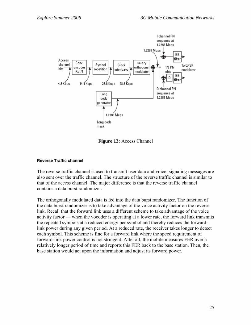
The access channel is used by the mobile to communicate with the base station when the mobile doesn’t have a traffic channel assigned. The mobile uses this channel to make call originations and respond to pages and orders. The baseband data rate of the access channel is fixed at 4.8 Kbps. As shown in Figure 13, the baseband information is first error protected by an R = 1/3 convolutional encoder. The lower encoding rate makes error protection more robust on the reverse link, which is often the weaker of the two links. The symbol repetition function repeats the symbol once, yielding a code symbol rate of 28.8 Ksps (Kilo-Samples per Second). The data is then interleaved to combat fading.
Explore Summer 2006 3G Mobile Communication Networks
25
Figure 13: Access Channel
Reverse Traffic channel
The reverse traffic channel is used to transmit user data and voice; signaling messages are also sent over the traffic channel. The structure of the reverse traffic channel is similar to that of the access channel. The major difference is that the reverse traffic channel contains a data burst randomizer. The orthogonally modulated data is fed into the data burst randomizer. The function of the data burst randomizer is to take advantage of the voice activity factor on the reverse link. Recall that the forward link uses a different scheme to take advantage of the voice activity factor — when the vocoder is operating at a lower rate, the forward link transmits the repeated symbols at a reduced energy per symbol and thereby reduces the forward-link power during any given period. At a reduced rate, the receiver takes longer to detect each symbol. This scheme is fine for a forward link where the speed requirement of forward-link power control is not stringent. After all, the mobile measures FER over a relatively longer period of time and reports this FER back to the base station. Then, the base station would act upon the information and adjust its forward power.

Explore Summer 2006 3G Mobile Communication Networks
26
Special Interest Areas
Interested Areas CDMA2000 being a new member in the science and technology is in a premature state. Research is still being carried out in this field. The major areas includes enhancements in the data rate, less computations, backward compatibility of the systems of previous generations, Better Spectral Efficiency, Easy Upgrade Path, O-CDMA and many more. Some of the areas of interest are discussed below:
• Optical Fiber Communication using CDMA Technologies • Downlink Admission/Congestion Control and Maximal Load in CDMA Networks • Load Balancing in WCDMA by Adjusting Pilot Power • Capacity Reduction of WCDMA Downlink in the Presence of Interference From
Adjacent Narrow-Band System
Contacted Institution During the research work we have contact QUALCOMM for some help in order to understand the topic. Following documents are provided by QUALCOMM
• Video Lecture for CDMA Course • Slides for CDMA Course
Contacted Personnel During our research we contacted different personnel how got certification from QUALCOMM in CDMA2000. These are follows
• Mr. Ahsan Chaudary ([email protected]) • Dr. Ismail Shah ([email protected])
Research Undergoing in Specified Area
Optical Fiber Communication using CDMA This is related to the use of CMDA concepts in optical fiber communications. A non-coherent synchronous optical fiber code-division multiple-access (CDMA) network is proposed. In this network, sequence-inversion keying (SIK) of intensity modulated unipolar balanced Walsh code sequences is employed, whereby a code sequence is transmitted for each data ‘1’ bit while the logical complement of that sequence is transmitted for each data ‘0’ bit. At the receiver the received optical signal is correlated with the bipolar form of the reference sequence. Since the code sequences are balanced and the unipolar-bipolar correlation is implemented the same correlation functions as a bipolar system can be obtained. Hence, in the proposed synchronous optical fiber CDMA
Explore Summer 2006 3G Mobile Communication Networks
27
network, the cross-correlation of the address sequence and the undesired sequences is zero, that is, the interference is completely eliminated. Therefore, a very large number of users can transmit at the same time and very high throughput can be achieved. The novel design of programmable transmitter and receiver for non-coherent synchronous optical fiber CDMA networks using balanced Walsh codes is also presented. The transmitter and receiver are designed based on the use of electro-optical switches and optical delay-lines. This idea is discussed in [1]
Difference between WCDMA with CDMA2000 With the introduction of the third generation systems (IMT-2000), second generation capabilities (voice and low/medium rate data) are extended adding multimedia capabilities to second-generation platforms such as support for high bit rates and introduction of packet data/IP access. In this paper the technical features of the two IMT-2000 radio interface proposals, ARIB/ETSI’s WCDMA and TIA’s cdma2000, are discussed and a comparison is being made regarding their performances. After the similarities are given briefly, the study is more focused on the differences that are affecting the performance. Main issues of the differences are examined in detail to find out the benefits or the drawbacks that those issues bring to each proposal. This is discussed in details in [2]. Some other research papers are also read during the ES2006 discussed in [3], [4], [5]

Explore Summer 2006 3G Mobile Communication Networks
28
References
Reference Research Papers [1] “Synchronous Optical Fiber Code Division Multiple Access Networks Using
Walsh Code” by Pham Manh Lam and Keattisak Sripimanwatt – IEEE 7th Int. Symp. on Spread Spectrum Tech & Appl., Prague, Czech Republic, Sept 2-5, 2002
[2] “Downlink Admission/Congestion Control and Maximal Load in CDMA
Networks” By Fran¸cois Baccelli, Bartłomiej Błaszczyszyn & Florent Tournois - 0018-9545/02$17.00 © 2002 IEEE
[3] “Capacity Reduction of WCDMA Downlink in the Presence of Interference
from Adjacent Narrow-Band System” by Kari Heiska, Harri Posti, Peter Muszynski, Pauli Aikio, Jussi Numminen, and Miikka Hämäläinen – 0018-9545/02$17.00 © 2002 IEEE
[4] “A Comparison Study of 3G System Protocols: CDMA2000 VS. WCDMA” by
Emre A. Yavuz and Dr. Victor Leung [5] “Load Balancing in WCDMA Systems by Adjusting Pilot Power” by Nagaike,
R. Harmen, S. Nokia Res
Reference URLs 1. http://www.radio-
electronics.com/info/cellulartelecomms/cellular_concepts/cellular_concept.php 2. http://www.umtsworld.com/technology/cdma2000.htm 3. http://www.radio-electronics.com/info/cellulartelecomms/cdma-
sys/cdmaintro/cdmaintro.php 4. http://www.mobiledia.com/glossary/17.html 5. http://www.sss-mag.com/ss.html#tutorial 6. http://www.umtsworld.com/technology/cdma2000.htm 7. http://www.umtsworld.com/technology/wcdma.htm 8. http://www.telecomspace.com/3g.html 9. http://en.wikipedia.org/wiki/Duplex_(telecommunications) 10. http://www.cdmaonline.com/interactive04/flash.html 11. http://www.cdmaonline.com/members/flash/demo/revlinkopt/flash.html 12. http://www.cdmaonline.com/members/workshops/terms1/index.htm

Explore Summer 2006 3G Mobile Communication Networks
29
Reference Books
13. “CDMA RF System Engineering” by Samuel C. Yang 14. “CDMA System Engineering Hand Book” by Jhong Sam Lee and Leonard E.
Miller 15. “Digital Communication over Fading Channels” by Marvin K. Simon and
Mohamed-Slim Alouini 16. “TDD-CDMA for Wireless Communications” by Riaz Esmailzadeh and Masao
Naka- gawa 17. “Principle of WCDMA” by M.R. Karim 18. “CDMA Mobile Radio Design” by John B. Groe Lawrence E. Larson 19. “Digital and Analog Communication Systems” by Couch,II 20. “Modern Digital and Analog Communication Systems” by B.P.Lathi 21. “CDMA Principle of Spread Spectrum” by Viterbi 22. “Introduction to 3G Mobile Communication” by Juha Korhonen 23. “”
Workshops and Seminars
24. “3G and NGN Languages” conducted by Dr. Tanveer ul Haq at NIIT-NUST 25. “Introduction to Digital Communication and CDMA2000” conducted by Dr.
Ismail Shah at NIIT-NUST 26. HONET conducted by NIIT-NUST