3d1405606841_1820eb0d3ff43355627231f6ba3d01e8
DESCRIPTION
3d1405606841_1820eb0d3ff43355627231f6ba3d01e8TRANSCRIPT

Marine Geology 286 (2011) 65–81
Contents lists available at ScienceDirect
Marine Geology
j ourna l homepage: www.e lsev ie r.com/ locate /margeo
Seabed morphology and shallow sedimentary structure of the Storfjorden andKveithola trough-mouth fans (North West Barents Sea)
M.T. Pedrosa a,⁎, A. Camerlenghi a,b, B. De Mol c, R. Urgeles d, M. Rebesco e, R.G. Lucchi a,e
and shipboard participants of the SVAIS and EGLACOM Cruises 1
a Departament d'Estratigrafia Paleontologia y Geociències Marines. Facultat de Geología, Universitat de Barcelona, Spainb ICREA, Istitució Catalana de Recerca i Estudis Avançats, Barcelona, Spainc Parc Cientific de Barcelona, Universidad de Barcelona, Spaind Departament de Geologia Marina, Institut de Ciències del Mar (CSIC), Barcelona, Spaine Istituto Nazionale di Oceanografia e di Geofisica Sperimentale, OGS, Trieste, Italy
⁎ Corresponding author. Tel.: +34 691 34 21 80; fax:E-mail address: [email protected] (M.T. Pedrosa).
1 SVAIS cruise participants: D. Amblas, A. Calafat, M.Frigola, O. Iglesias, S. Lafuerza, G. Lastras, C. Lavod'Estratigrafia Paleontologia y Geociències Marines. Fade Barcelona, Spain); E. Colmenero Hidalgo, J.A. FloresGeologia, Universidad de Salamanca, Spain); A. Caburlottdi Oceanografia e di Geofisica Sperimentale, OGS, Tr(Department of Geology, University of Tromsø, Norway)F. Zgur, M. Rebesco, D. Deponte, C. De Vittor, L. FacchCaburlotto, C. Pelos (OGS), G. Perissinotto, N. FerOceansismica).
0025-3227/$ – see front matter © 2011 Elsevier B.V. Aldoi:10.1016/j.margeo.2011.05.009
a b s t r a c t
a r t i c l e i n f oArticle history:Received 1 October 2010Received in revised form 14 April 2011Accepted 11 May 2011Available online 14 June 2011
Communicated by D.J.W. Piper
Keywords:Barents SeaSvalbardStorfjordenPaleo-ice streamsglacial maximumdeglaciation
This study aims to present an overview of the seafloor morphology and shallow sedimentary structure of theStorfjorden and Kveithola Trough Mouth Fans (TMFs) on the northwestern Barents Sea continental margin.Data have been compiled from two International Polar Year (IPY) cruises (SVAIS, of the BIO Hespérides andEGLACOM of the R/V OGS-Explora) that yielded 15,340 km2 of multi-beam bathymetry and 9500 km of sub-bottom seismic profiles. In this area, the continental shelf edge defines three wide and subdued sedimentarylobes forming Storfjorden TMF, one single lobe on Kveithola TMF, and three inter-TMF areas on thecontinental slope. The two northernmost lobes of Storfjorden TMF (Lobes I and II) are composed by thick (upto 50 m) sequences of glacially derived debris flow deposits interbedded with thin a fewmetres de-glacial andinterglacial deposits. A network of upper slope gullies incises these debris flow deposits as a consequence ofsubglacial meltwater release at or near the shelf break. Gullies evolve into channels whose morphologicevidence disappears midslope, leaving place to a subdued chevron-like morphological pattern inherited bythe preceeding glacial maximum debris flow deposits. A drastic change occurs on the continental slope ofStorfjorden TMF Lobe III and Kveithola TMF, where are several translational submarine landslides mostlyoriginated in the upper slope, the majority of which detach at the contact between Middle Weishelianglacigenic debris flows and the overlying acoustically laminated plumites. Dendritic canyon systems onlydevelop in inter-TMF areas. The data suggest that TMF continental slope progradation depends on short-livedepisodes of extreme sedimentation during glacial maxima and during the early deglaciation phase, and thatan important controlling factor is the mechanism of ice stream retreat from the continental shelf edge. Wesuggest that the two northern Storfjorden sub-ice streams were composed of thicker and perhaps faster iceprogressively draining a distal and larger ice source mainly located on Svalbard. Conversely, the southernmostStorfjorden sub-ice stream and the Kveithola ice stream were fed by a local, smaller marine-based ice domegrounded on Spitsbergenbanken. The ice dome persisted after the LGM, maintaining a local ice drainagesystem close to the shelf edge whose sedimentary evidence can be found on the continental slope of thesouthern lobe of Storfjorden TMF and Kveithola TMF. The high degree of lateral variability in the style ofsedimentation on TMF slopes suggests that ice stream dynamics may vary considerably within the sameglacial trough, and that such variability affects the long-term development of the architecture of TMFs.
+34 934 02 13 40.
Canals, J.L. Casamor, S. Costa, J.ie, C. Liquete (Departamentcultat de Geología, Universitat, F.J. Sierro (Departamento deo, M. Grossi (Istituto Nazionaleieste, Italy); M. Winsborrow. EGALCOM cruise participants:in, I. Tomini, R. De Vittor, A.rante, E. Di Curzio (FUGRO
l rights reserved.
© 2011 Elsevier B.V. All rights reserved.
1. Introduction
Trough mouth fans (TMFs; Nansen, 1904; Vogt and Perry, 1978;Vorren et al., 1988, 1989) are sedimentary depocentres characterised byoutbuilding of the upper slope in a seaward-convex sedimentary fanmade of alternating prograding and aggrading sequences that deriveprimarily from debris flows accumulation at the front of glacial troughson continental shelves (e.g. Laberg and Vorren, 1995; Vorren andLaberg, 1997; Dahlgren et al., 2005). These troughs hosted ice streams,which have been suggested as the main mechanism of glacial sediment
Nor
way
Spitsbergen
Storfj
orden
Tro
ugh
Kveithola Trough
BIF
SF
BeF
IF
KF
SvalbardArchipelago
BarentsSea
Fram Strait
Norwegian-GreenlandSea
Bjørnøya
Bjørnøya Tro
ugh
Edgeøya
0 kilometres125
Nordaustlandet
Gre
enla
nd
Nor
way
Svalbard
Kn
ipo
vich R
idg
e
Hopen
Spitsber
gen-
banke
n
250
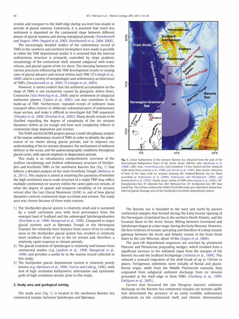
Fig. 1. Colour bathymetry of the western Barents Sea obtained from the grid of theInternational Bathymetric Chart of the Arctic Ocean (IBCAO) after Jakobsson et al.(2008) (URL: http://www.ibcao.org). Grid resolution 1.5 km. Dotted red line: RegionalLGM extent from Landvik et al. (1998) and Vorren et al. (1989). Blue arrows: Directionof flow of the main LGM ice streams draining the Svalbard/Barents Sea Ice Sheetaccording to Andreassen et al. (2008), Andreassen and Winsborrow (2009), andDowdeswell et al. (2010). Purple areas: extent of TMFs from Sejrup et al. (2005): KF:Kongsfjorden Fan; IF: Isfjorden Fan; BeF: Bellsund Fan; SF: Storfjorden Fan; BIF: BearIsland Fan. The red box outlines the SVAIS-EGLACOM study area. Bold black dotted line:Inferred glacial drainage area of the Storfjorden-Kveithola depositional system.
66 M.T. Pedrosa et al. / Marine Geology 286 (2011) 65–81
erosion and transport to the shelf edge during sea level low-stands inperiods of glacial maxima. Conversely, it is assumed that much lesssediments is deposited on the continental slope between differentphases of glacial maxima and during interglacial periods (Dowdeswelland Siegert, 1999; Nygård et al., 2002; Dowdeswell et al., 2004, 2006).
The increasingly detailed studies of the sedimentary record ofTMFs in the southern and northern hemisphere have made it possibleto refine the TMF depositional model. It is assumed that the internalsedimentary structure is primarily controlled by slope gradient,morphology of the continental shelf, amount subglacial melt waterrelease, and glacial regime of the ice sheet. The interplay between thevarious processes influencing the TMF development results in varyingrates of glacial advance and retreat within each TMF (Ó Cofaigh et al.,2008) and in a variety of morphologies and sedimentary architecturesof TMFs (Dowdeswell et al., 2002; Ó Cofaigh et al., 2003).
However, it seems evident that the sediment accumulation on theslope of TMFs is not exclusively caused by glacigenic debris flows.Contourite (Van Weering et al., 2008) and/or settlement of subglacialmeltwater plumes (Taylor et al., 2002) can also contribute to thebuild-up of TMF. Furthermore, repeated events of sediment masstransport often remove or obliterate substantial parts of sedimentaryslope section, and make it difficult to investigate full TMF sequences(Dimakis et al., 2000; Elverhøi et al., 2002). Many details remain to beclarified regarding the degree of complexity of the ice streamsdynamics within an ice trough and how such complexity reflects incontinental slope deposition and erosion.
The SVAIS and EGLACOMprojects pursue amulti-disciplinary analysisof the marine sedimentary record of TMFs in order to identify the paleo-extent of ice sheets during glacial periods, and to improve ourunderstanding of the ice streams dynamics, the mechanisms of sedimentdelivery to the ocean, and the paleoceanographic conditions throughoutglacial cycles, with special emphasis to deglaciation periods.
This study is an introductory comprehensive overview of theseafloor morphology and shallow sedimentary structure of Storfjor-den and Kveithola TMFs in the northwest Barents Sea (Fig. 1) thatfollows a detailed analysis of the outer Kveithola Trough (Rebesco etal., 2011). This analysis is aimed at resolving the questions of whetherthe high-resolution macro-scale structure of a single TMF may reflectmultiple continental ice sources within the same paleo-ice stream, ofwhat the degree of spatial and temporal variability of ice streamsretreat after the Last Glacial Maximum (LGM) is, and of how glacialdynamics controls continental slope accretion and erosion. The studyarea was chosen because of three main reasons:
1) The Storfjorden glacial system is relatively small and is sustainedby a small catchment area with local provenance from theemerged land of Svalbard and the submerged Spitsbergenbanken(Elverhøi et al., 1998; Mangerud et al., 1998). Compared to majorglacial systems such as Bjørnøya Trough or the NorwegianChannel, the relatively short distance from source of ice to calvingareas in the Storfjorden glacial system has resulted in relativelyshort residence times of ice in the ice stream and, therefore, arelatively rapid response to climate periods;
2) The glacial evolution of Spitsbergen is relatively well known fromcontinental studies (e.g. Landvik et al., 1998; Mangerud et al.,1998) and provides a useful tie to the marine record collected inthis study;
3) The Storfjorden glacial depositional system is relatively poorlyknown (e.g. Hjelstuen et al., 1996; Vorren and Laberg, 1996), withlack of high resolution bathymetric information and systematicgrids of high resolution seismic prior to this study.
2. Study area and geological setting
The study area (Fig. 1) is located in the northwest Barents Seacontinental margin, between Spitsbergen and Bjørnøya.
The Barents Sea is bounded to the west and north by passivecontinental margins that formed during the Early Eocene opening ofthe Norwegian–Greenland Sea in the northern North Atlantic, and theEurasian Basin in the Arctic Ocean. Rifting between Greenland andSpitsbergen began at a later stage, during the EarlyMiocene. However,the first evidence of oceanic spreading and therefore of a deep oceanicgateway between the Arctic and Atlantic oceans in the Fram Straitdates to the Late Miocene, about 10 Ma (Engen et al., 2008).
The post-rift depositional sequences are overlain by prominentPliocene and Pleistocene prograding wedges, which resulted from asignificant increase in the sediment input from the margins of theBarents Sea and the Svalbard Archipelago (Solheim et al., 1998). Thisinduced a seaward migration of the shelf break of up to 150 km inplaces. Terrigenous sediments were initially of fluvial and glacio-fluvial origin, while from the Middle Pleistocene onwards, theyoriginated from subglacial sediment discharge from ice streamsgrounded at the shelf edge to form TMFs (Forsberg et al., 1999;Dahlgren et al., 2005).
Factors that favoured the late Neogene massive sedimentdischarge on the Barents Sea continental margins are tectonic uplift,that determined the presence of an easily erodible sedimentarysubstratum on the continental shelf, and climatic deterioration

SpitsbergenEdgeøya
Bjørnøya
Kveithola Trough
StorfjordenTrough
100 m200 m300 m
Spitsbergenbanken
Barents Sea
0 50 100kilometres
LegendEGLACOMSVAISCoast line
Storfjord-banken
Hopen-banken
Hopen
NordFlaket
Fig. 2. Ship tracks from BIO Hespérides SVAIS and R/V OGS-Explora EGLACOM cruises.Contour interval 100 m. Grey-scale shaded-relief bathymetry results from a merge ofthe grid of the International Bathymetric Chart of the Arctic Ocean (IBCAO) afterJakobsson et al. (2008) http://www.ibcao.org (horizontal resolution 1.5 km) and a gridproduced by the Geological Survey of Norway (Ottesen et al., 2006; horizontalresolution 0.5 km). Illumination from azimuth 340°, 45° incidence angle, no verticalexaggeration.
67M.T. Pedrosa et al. / Marine Geology 286 (2011) 65–81
towards colder periods that culminated with the increased erosion bygrounded ice (e.g. Elverhøi et al., 1998; Ó Cofaigh et al., 2003).
Continental ice gradually occupied the Barents Sea during theonset of the northern hemisphere glaciations. In the Late Pliocene(3.6–2.4 Ma), the ice sheet reached the continental shelf only in thenorthern Barents Sea during short-term episodes of ice expansion.From the Late Pliocene to the Middle Pleistocene (2.4–1.0 Ma) the icesheet expanded towards the southern Barents Sea from theScandinavian Peninsula. It was only after 1.0 Ma that the ice sheetsexpanded over the entire Barents Sea reaching the shelf edge duringglacial maxima (Vorren and Laberg, 1997; Knies et al., 2009).
The Barents Sea is underlain by a broad continental shelfcharacterised by shallow banks separated by deeper glacial troughs.The glacial troughs hosted the major ice streams that drained fast icetowards the continental shelf break. Banks hosted slow moving icewith less erosive capacity. The continental shelf seabed morphologyallows reconstructing past ice drainage within the Barents Sea icesheet (Fig. 1; Winsborrow et al., 2009).
The Storfjorden Trough (Fig. 1) is 254 km long, about 40 km widein the inner continental shelf and up to 125 kmwide at the shelf edge.It covers approximately an area of 38,000 km2. Water depth along thetrough axis varies between 150 m around its rim and 420 m recordedin its middle part. The Storfjorden TMF extends from the shelf break(approximately 420 m water depth) towards the Knipovich ridge, inwater depth of about 2300 m. Its average gradient varies between 0.2°and 1.8° (Vorren and Laberg, 1996).
The Storfjorden TMF begun to develop approximately in the LatePliocene (2.3–2.5 Ma), even if records of older sediments date back to55 Ma (Hjelstuen et al., 1996, 2007). The main progradation of the fanlasted until 0.2 Ma, with a fast prograding phase between 1.3 and 1.5and 0.2 Ma (Hjelstuen et al., 2007; Knies et al., 2009). In the last0.2 Ma, sedimentation appears to be more evenly distributed on theentire northwest Barents Sea margin, including the Storfjorden TMF,as a consequence of the decreased sediment input and the lateralspread of sediment particles by contour currents and melt waterplumes (Vorren et al., 1998).
The Kveithola Trough is a small E–W trending cross-shelf glacialtrough located between Storfjorden Trough and Bjørnøya. Firstreported by Vorren et al. (1998), it has been identified as a potentialsource of melt water to the continental slope by Fohrmann et al.(1998). The seafloor in Kveithola Trough is characterised by familiesof E–W trending mega-scale glacial lineations that record a fastflowing ice stream draining the Svalbard and Barents Sea ice sheetsduring the LGM. Glacial lineations are overprinted by transverseGrounding-Zone Wedges (GZW) that give rise to a staircasebathymetric axial profile of the trough. The sedimentary drapedeposited on top of the GZWs accumulated at a very high rate inthe order of 1 m ka−1 (Rebesco et al., 2011).
3. Data and methods
All data presented in this article (Fig. 2) were collected during BIOHespérides IPY Cruise SVAIS (Longyearbyen, July 29–August 17 2007)and R/V OGS-Explora IPY Cruise EGLACOM (Kristinsund, July 07–August 04 2008). Ship navigation was secured by means of D-GPS andinertial navigation systems (Kongsberg Seapath 200 on board the BIOHesperides and Ixsea PHINS onboard the OGS-Explora). The jointmultibeam bathymetric survey area covered by the SVAIS andEGLACOM cruises is about 15,340 km2 (8220 km2 and 7120 km2
respectively). The total length of acquired sub-bottom profiler data isnearly 9500 km.
3.1. Bathymetry
The BIO Hespérides employed multi-beam echo-sounders SimradEM120 (operating at a mean frequency of 12 kHz) and Simrad
EM1002S (operating at a mean frequency of 95 kHz) for deep andshallow water sounding respectively. Both echo-sounders werecalibrated prior and during the survey. The sound velocity profilewas obtained with the launch of nine XBT probes throughout thesurvey.
The R/V OGS-Explora employed multi-beam echo-sounders ResonMB8150 (operating at a mean frequency of 12 kHz) and MB8111(operating at a mean frequency of 100 kHz) for deep and shallowwater sounding respectively. Both systems were calibrated during thepreceding cruise. The sound velocity profiles were obtained with 6casts of the Reson SVP24 Sound Velocity Probe and XBT launches. Inaddition, continuous velocity values used to perform the dynamicbeam steering are provided by the keel mounted Navitronic SVP71sound velocity probe.
On the BIO Hespérides, multi-beam bathymetric data were loggedusing Simrad's Mermaid system and processed with Caris HIPS andSIPS V 6.1. Data processing included a careful manual editing of allbeams in order to remove acquisition noise caused by rough seaconditions. The data of the Simrad EM120 echo-sounder werenegatively affected especially in deep waters by a down-warddeflection of the sea bottom profile on the port side beams. Thecause of this artefact was later identified by Kongsberg in the ship keelacoustic window and corrected in post-processing.
On the R/V OGS-Explora, multi-beam bathymetric data were loggedand processed with the Reson PDS2000 V 2.5.3.2 software. Fordatasets of both cruises, editing steps included: 1) application ofcalibration parameters (time-pitch-roll-yaw) and sound velocityprofiles to the swaths; 2) editing of spurious navigation points; 3)application of beam number, depth, quality, nadir and statistic filtersfor every line and 4) manual editing of each line.

Fig. 3. Merge of three bathymetric data sets over the study area: 1) High resolution,grey-scale shaded-relief bathymetry of the Storfjorden and Kveithola TMFs resultingfrom the SVAIS and EGLACOM bathymetric grids on the middle–upper continentalslope and outer shelf. Horizontal resolution 200 m. Illumination from the north,incidence angle 40°, azimuth 355°N. 2) Shaded relief bathymetry from the GeologicalSurvey of Norway (Ottesen et al., 2006; horizontal resolution 0.5 km). Contour lines at100 m interval. In order to outline small bathymetric changes on the outer shelf, acolour scale has been applied between 200 and 420 m water depth. 3) InternationalBathymetric Chart of the Arctic Ocean (IBCAO) after Jakobsson et al. (2008) http://www.ibcao.org (horizontal resolution 1.5 km) on the continental slope outside thesurvey area. Contour lines at 100 m interval.
68 M.T. Pedrosa et al. / Marine Geology 286 (2011) 65–81
The final Digital Terrain Model was produced from the combineddata set with 75 m grid spacing and exported to ArcGis V 9.3 for dataanalysis and display. Additional software used for better datavisualisation and analysis were Surfer 8.0, Global Mapper 11,Fledermaus View 3D, Mirone 1.4.0.
3.2. Subbottom profiling
The Kongsberg TOPAS PS 18 hull-mounted parametric sub-bottomprofiler was used on the BIO Hespérides simultaneously with multi-beam data acquisition. The profiler uses two primary frequenciesranging between 16 and 22 kHz to produce a narrow beam secondaryfrequency ranging between 0.5 and 6.0 kHz. All data were sampled at16 kHz and stored both in the raw proprietary format and SEG-Yformat. During the cruise all TOPAS profiles were imported in SeismicMicro-Technology's Kingdom Suite 8.3 software after some SEG-Yheader editing using Gedco's Vista 7.1. The data quality was excellentthroughout the cruise with the exception of a few days with bad seastate.
The hull-mounted Benthos CAP-6600 sub-bottom chirp profilerwas used on the R/V OGS-Explora. This echo-sounder uses a sweep ofacoustic frequencies ranging between 2 and 7 kHz. CommunicationTechnology's SwanPro acquisition software was used to collect thedata in XTF format and subsequently converted to SEG-Y. At OGS anintegrated interpretation of all data was performed using SeismicMicro-technology's Kingdom Suite.
The conversion from two-way travel time to depth is made using areference sound velocity in sediments equal to 1500 m s−1. Thisimplies a probable underestimation of thickness that ranges fromapproximately 0% in the uppermost metres of sediments to 6.5–13.3%in the deepest units imaged by the sub-bottom profiler, in which thesound velocity could be ranging easily between 1600 and 1700 m s−1.
4. Results
The morphology of the outer continental shelf and mid-uppercontinental slope of the Storfjorden and Kveithola TMFs is describedusing the combined multibeam bathymetric dataset from the twosurveys (Fig. 3) merged with the grid produced by the GeologicalSurvey of Norway (Ottesen et al., 2006).
4.1. Outer continental shelf morphology
The overview bathymetry available in the area (Fig. 3; Ottesen etal., 2006) reveals that the outer fan-shaped part of Storfjorden Troughcomprises three large lows (broad channels) separated by elevations(outer banks) close to the shelf edge. The water depth in theseschannels increases from north to south (340 m, 364 m, and 378 mrespectively). The northernmost bank, here definded Outer Bank 1 is317 m deep, while the southern Outer Bank 2 is 344 m deep (Fig. 3). Asmaller sized 358 m deep outer bank is also present close to the shelfedge in the middle part of Kveithola Trough (Rebesco et al., 2011). Aprominent fan-shaped bathymetric step of about 100 m of elevationdefines the transition between the outer and middle shelf (BS inFig. 3).
The high resolution seafloor morphology of the southern Storfjor-den Through outer continental shelf is dominated by three types ofseabed features (Figs. 3 and 4A): 1) Linear or slightly curved furrowsof apparently random strike, with either V-shaped or U-shapedprofile, 2) Large-scale lineations, composed of two families of largeridge-groove rectilinear structures each composed of three to fourparallel grooves bounded by marginal sediment ridges. These large-scale lineations are about 1.5 km wide, up to 20–25 km long, 15 to20 m deep with a NNE–SSW trend. The marginal ridges are less than10 m high above the surrounding seafloor, (Fig. 4A, B). 3) A lobatemoraine is present close to the shelf edge. The moraine has a highly
curved shape in plain view, with a NNE–SSW direction of elongation,is about 8 km wide and about 20 m high. The external part of thismoraine appears to be interrupted by a groove-ridge structure(Fig. 4A).
4.2. Continental slope and shelf edge morphology
The continental shelf edge defines three broad and morphologi-cally subdue sedimentary prograding lobes in the Storfjorden TMF,each separated by an outer shelf bank. Each of these sectors definesareas of the continental slope with distinctive seabed morphology.
4.2.1. Storfjorden TMF Lobe IThe continental shelf edge on Lobe I is located approximately along
the 420 m isobath and separates a nearly flat continental shelf from anupper continental slope dominated by an extensive network of gullies(Fig. 5A). The uppermost slope is characterised by a steep (in placesexceeding 3°) and narrow (about 1 to 2 km) segment bordering theshelf edge (Fig. 5B). Further downslope, the slope gradient decreasesto a rather uniform value between 0.5° and 1.5°. Gullies never cut backdeeply into the continental shelf, are typically 5 to 20 km long andextend downslope to 900–1000 m water depth. They are nearlystraight or have a low sinuosity, and are generally less than 10 m deepwith respect to the surrounding seafloor. The gullies' side slope angleis about 1°, locally up to about 2.5°. The spacing between gullies varies

0.6
0.5
0.4
450050005500SP
TW
TTi
me
(s)
FurrowsLarge scale lineations
Upper Regional Unconformity
NW SE
1 km
NW Lobate moraine
SW Lobate moraine
B
0 2 4 kilometres
1
22
3
Large scalelineations
Lobatemoraine
75°2
0'N
15°10'E15°0'E14°50'E14°40'E
75º3
0'N
Furrows
Large scalelineations
Mar
gina
l rid
ge
Mar
gina
l rid
ge
Marginal ridge Marginal ridge
L 69
L69
AN
Fig. 4. A). Grey-scale shaded relief bathymetry of a part of Storfjorden outer continental shelf. Illumination is from the NNW (335°), incidence angle 30°. B) Sub-bottom profiler L 69representative of the main morphological elements of a part of the Storfjorden outer continental shelf. The vertical exaggeration in the subbottom profiler is 60×.
400
600
800
Chevronmorphologicpattern
LOB
E I
L8
Network ofgullies
A1000
1200
1400
1600
13°20'E 13°40'E 14°0'E 14°20'E 14°40'E
76°0
'N76
°20'
N
0 - 0.50.5 - 1.51.5 - 2.02.0 - 2.52.5 - 3.0
kilometres0 5 10
B
14°40'E13°20'E 13°40'E 14°0'E 14°20'E
76°0
'N76
°20'
N
kilometres0 5 10
Fig. 5. A) Grey-scale shaded relief bathymetry of the continental slope of Storfjorden TMF Lobe I. B) Slope gradient of the same area imaged in A. Illumination is from the N (355°),incidence angle 40°. Note the artefacts induced by slope-parallel ship tracks and by mismatch in water depths between the two surveys. The relatively even topographic relief of thearea causes a low signal-to-noise ratio. Outline of the area in Fig. 3. Sub-bottom profile L8 is imaged in Fig. 10B. See text for discussion.
69M.T. Pedrosa et al. / Marine Geology 286 (2011) 65–81

70 M.T. Pedrosa et al. / Marine Geology 286 (2011) 65–81
between 200 and 1000 m. The gullies branch in the uppermoststeepest slope into a third-order dendritic network of short tributarygullies. Their cross section profiles changes from V-shaped to U-shaped in deeper water attaining the morphological characteristics ofcontinental slope channels with a typical width of about 1 km.
The morphologic evidence of gullies and channels disappears inwater depths deeper than about 1200 m, where the sediment surfaceof the continental slope is made of an alternation of subdued highsand lows producing a subtle chevron morphologic pattern elongatedin direction approximately perpendicular to the contour lines.Individual chevrons show a mounded topography when displayedin cross section and develop in most instances at the mouth of gulliesand channels. The apex angle of the chevrons is about 30°.
4.2.2. Storfjorden TMF Lobe IIOff the continental shelf edge of Lobe II the segment of steepest
slope is narrower than in Lobe I, usually not exceeding 1 km in width(Fig. 6). Elsewhere, the average slope gradients of the slope are similarto Lobe I. The gullies' depth, width and the side slope angle in theuppermost slope are comparable to those of Lobe I. However, thedensity of gullies is higher in Lobe II, with inter-gully spacing as shortas about 100 m, while the dendritic pattern on the uppermost slopeoften reaches the fourth order tributary level, with confluences oftributary gullies with the first order gully found at about mid-slope.The gullies length is up to 20 km.
Also the gullies of Lobe II change the cross profile from V-shaped toU-shaped at about mid slope, in water depth between 700 and1000 m, attaining a morphology more typical of straight or lowsinuosity continental slope channel. Evidence of early stage of gullydevelopment (inset in Fig. 6A) are observed in this water depth range,resulting in broader anastomosed channels patterns that include relictsegments of the continental slope completely surrounded by channels(Fig. 6A). The side slope of the anastomosed channels is steeper thanthat of the gullies upslope, reaching 2.5°–5° (Fig. 6B). Mid-slopechannels can attain a incision profile exceeding 30 m with respect tothe surrounding seafloor and can be more than 1 km wide. Thesecontinuous gully channels generated from the gullies capture systemhave a width up to 2–3 km.
Networks ofgullies
Chevronmorphologicpattern
LO
BE
II500
700
900
Chann
1100
1300
1500
L4
L12
L13
400
13°20'E 13°40'E 14°00'E 14°20'E 14°40'E
75°2
0'N
75°4
0'N
kilometres0 5 10
Fig. 6. A) Grey-scale shaded relief bathymetry of the continental slope of Storfjorden TMF Loincidence angle 40°. Note the artefacts induced by slope parallel ship tracks. The relatively evFig. 3. Sub-bottom profiles L4, L12 and L13 are imaged in Figs. 9A, B, and 10A respectively.
Gullies disappear on Lobe II in water depths deeper than about1000 m, leaving place to a chevrons morphologic pattern.
4.2.3. Storfjorden TMF Lobe IIIA drastic morphologic change occurs on the continental slope of
Lobe III with respect to that of Lobes I and II (Fig. 7). The slope angle issteeper (up to 3°) in a narrow segment right off the continental shelfedge. This segment widens from about 1 km to nearly 10 km in thesouthernmost area of Lobe III throughout the transition to the slope ofthe Kveithola TMF further to the SE. The overall morphologic patternof the continental slope is disturbed by changes induced byamphitheatre-like depressions of various sizes reflecting the headand side walls of submarine landslides.
In the northern part of Lobe III the discontinuous gullies thatdevelop on the upper continental slope are wider (200–500 m),deeper incised (7–14 m) and longer (20–50 km) than the onesobserved on Lobes I and II. Furthermore, they are straight withtributaries of only second order. These branching gullies are foundonly in the uppermost slope section. As in Lobes I and II the gullieswiden and deepen downslope leaving place at about 1200 m to a setof elongated chevron-like lobes.
To the south of these gullies, a wide sector of the upper continentalslope is characterised by shallow cresecent-shaped submarinelandslides scars (Fig. 7). The largest of them (Landslide 1 in Fig. 7)shows lateral scarps 35–40 m high and 3° to 4° steep that reach thecontinental shelf edge. The slope gradient within the scars rangesbetween 1° and 2°. The area enclosed by the shelf edge and the lateralscarps, as imaged by our surveys, covers an area of 1120 km2.Southeast of this scar, there are at least 12 additional minor bowl-shaped depressions on the upper continental slope each correspond-ing to submarine landslides. The scarps bounding these depressionsrange from 15 to 30 m in height. Table 1 summarises the morphologicparameters of the 5 largest submarine landslides in this sector of themargin.
4.2.4. Kveitehola TMFThe coalescence between Storfjorden and Kveithola TMFs is
outlined by a rather sharp change in the direction of morphologicallineations produced by the different orientation of the glacial troughs
el
BA
13°20'E 13°40'E 14°40'E14°20'E14°0'E
0 - 0.50.5 - 1.01.0 - 1.51.5 - 2.02.5 - 3.0kilometres0 5 10
be II. B) Slope gradient of the same area imaged in A. Illumination is from the N (355°),en topographic relief of the area causes a low signal-to-noise ratio. Outline of the area inSee text for discussion.

Fig.11B
L253
45
Landslides 3,4,5
Landslide 2
Landslide 1
L34-35
L11
LOBEIII
15°20’E15°0’E14°20’E14°0’E
74°4
0’N
74°2
0’N
15°20’E15°0’E14°20’E14°0’E
74°4
0’N
74°2
0’N
0 - 0.50.5 - 1.01.0 - 1.51.5 - 2.02.5 - 3.0
40060080010001200
1400
1600
kilometres0 5 10 kilometres0 5 10
A B
14°40’E 14°40’E
Fig. 7. A) Grey-scale shaded relief bathymetry of the continental slope of Storfjorden TMF Lobe III. B) Slope gradient of the same area imaged in A. Illumination is fromWNW (240°),incidence angle 60°. Note the artefacts induced by slope parallel ship tracks. The relatively even relief of the area causes a low signal-to-noise ratio. Outline of the area in Fig. 3. Sub-bottom profiles L11, L25, and L34-35, are imaged in Figs. 9C, 11B, and A respectively. See text for discussion.
71M.T. Pedrosa et al. / Marine Geology 286 (2011) 65–81
on the continental shelves (NE–SW and E–W respectively) (Figs. 3, 7,8A). The upper continental slope of Kveithola TMF is steeper than thatof Storfjorden TMF, with a steep upper slope segment as wide as10 km, characterised by straight gullies (Figs. 7A and 8A). In themiddle slope of Kveithola TMF we also find several bowl-shapeddepressions and elongated scars produced by submarine landslides.The most prominent of these is an elongated feature with a complexhead area located in 1300 m water depth. The scarps here are 30 mhigh, about 20 km long and enclose an area of about 50 km2.
4.2.5. Inter-TMF areasInter TMF areas are those facing the seaward-concave parts of the
continental shelf edge not associated with glacial troughs. Within thesurvey area, these are found in the northernmost part, bordering thenorthern edge of Lobe I of the Storfjorden TMF, between Storfjordenand Kveithola TMFs, and south of Kveitehola TMF (Fig. 3).
The best example of the morphological characteristics of theseparts of the margins is displayed south of Kveithola TMF (Fig. 8).Moving away from the trough mouth, the continental slope containsincreasingly large and deep straight channels that develop networksof small canyons in the upper slope converging at about 1000 mwaterdepth intomajor canyons. The previously described gullies–channels–chevron morphologic transition, from the upper to mid-slope, isabsent here. Between Storfjorden and Kveithola TMFs, the inter-TMFsarea is confined to the upper slope, because the two TMFs lobes mergeat about 1000 m water depth. The seafloor morphology is char-acterised by larger and deeper gullies intersected with bowl-shapedscarps (Fig. 7).
North of Lobe I of Storfjorden TMF is a tiny lobe facing a minorcontinental shelf trough northwest of which is an inter-TMF (Fig. 3)
Table 1Submarine landslides in the southwest of Storfjorden Fan (Lobe III). Main morphological fe
Submarine landslides Depth range (m) Length (km) Headwall length
Landslide 1 500–2200 60 15.5Landslide 2 1400–2200 20 8.5Landslide 3 600–800 6.3 3.2Landslide 4 600–800 6.5 2.1Landslide 5 600–800 1.2 1.3
part of the slope in which long-running gullies are imaged from shelfedge to mid-slope.
4.3. Continental slope shallow seismic structure
From top to bottom the continental slope of the Storfjorden andKveithola TMFs displays 4 major recent seismo-stratigraphic unitshere labelled from top down A to D. These seismic units are mostlydifferentiated on the basis of their seismic character, geometry, andreflector terminations. As we will show below, the areal distributionof these seismic units is strongly tied to the morphological featuresobserved on multibeam bathymetry.
4.3.1. Recent TMF stratigraphyThe deepest and poorly imaged Unit D has an irregular upper
boundary and hummocky internal configuration. The acousticbasement of the sub-bottom profiles is made of rather continuousfaint reflectors interpreted as the base of Unit D (Figs. 9, 10), whosethickness is at least 40 ms twt (in excess of 30 m). Below several largescars in the Storfjorden TMF, where the acoustic window penetratesdeeper in the stratigrphic section (Fig. 11A) evidence for a deeper unitbelow Unit D with a similar succession of subunits of alternating highamplitude continuous reflectors with intervals made of adjoiningtransparent lenses.
Unit C is characterised by high amplitude parallel to subparallelreflectors with high lateral continuity (Figs. 9B, C and 10). The unit iscomposed of an upper high amplitude part (C1) with thickness ofabout 10 ms twt (approximately 7.5 m), and a lower subunit with anaverage lower amplitude, at interval even faint amplitudes (trans-parent) (C2) with thickness up to 15 ms twt (about 11 m). The
atures.
(km) Headwall depth (m) Area (km2) Volume removed (km3)
Upper slope (500 m) 1120 33Mid slope (1000 m) 50 2Upper slope (600 m) 20 Not calculatedUpper slope (600 m) 10.7 Not calculatedUpper slope (600 m) 4.7 Not calculated

0 5 10
AKveithola TMF
Inter-TMF
area
L IT-EG-43
kilometres
16°20'E16°0'E15°40'E15°20'E
74°2
0'N
16°40'E
74°4
0'N
16°20'E16°0'E15°20'E 15°40'E
74°4
0'N
74°2
0'N
0 5 10kilometres
0 - 11 - 33 - 66 - 99 - 12
B
16°40'E
600800
1200
1000
1400
dendritic patternof small canyons
Fig. 8. A) Grey-scale shaded relief bathymetry of a part of the Kveithola TMF and the inter-TMF continental slope south of it. B) Slope gradient of the same area imaged in A.Illumination is from the NNW (340°), incidence angle 60°. Note the very steep slope angles (in excess of 10°) associated with the canyon system that do not exist on the StorfjordenTMF continental slope. Sub-bottom profile LIT-EG-43 is imaged in Fig. 10C. See text for discussion.
72 M.T. Pedrosa et al. / Marine Geology 286 (2011) 65–81
maximum thickness of Unit C is therefore less than 20 m. Only a fewpaleo-gullies are observed cutting in Unit C. No direct relationship hasbeen found between superficial paleo-gullies and Unit C. However,paleo-gullies appear to be draped by Unit C (Fig. 10A, C) so that weinfer that the paleo-gully formation is older than Unit C. The slidingsurface of submarine landslides corresponds to the base of Unit C.
Unit B is thick and omni-present in the surveyed continental slopeof Storfjorden TMF Lobes I and II. In Storfjorden TMF Lobe III and inKveithola TMF, Unit B is occasionally missing or it is reduced toindividual lenseswith thickness ranging from nearly zero to 20–30 mstwt (approximately 15–22.5 m; Fig. 9C). The basal reflector is oftenerosive. Where the unit is thinnest, a clear infill of erosive incisions inthe underlying Unit C (paleo-gullies, or paleo-channels) is observed(Fig. 9C).
The majority of the continental slope of Storfjorden and KveitholaTMFs is draped by a recent Unit A (Fig. 9). Unit A is of variablethickness ranging approximately 3.75 m on Storfjorden TMF Lobes Iand II (Figs. 9B, 10A, B), to about 15 m on Storfjorden TMF Lobe III andKveithole TMF (Fig. 11C). This unit is always composed of two parts:an upper part (A1) that varies from being completely transparent onStorfjorden TMF Lobes I and II, to roughly acoustically stratified as onStorfjorden TMF Lobe III and Kveithole TMF; a lower part (A2) that ishigh amplitude and continuously acoustically stratification.
4.3.2. Internal structure of gullies, channels, canyons, and chevronmorphology
Tributary gullies are clearly draped by recent sediments (Unit A;Fig. 9B, C; see TMF stratigraphy below). Conversely, the sedimentarydrape appears to be absent on first order gullies and slope channels,which cut into Unit A (Fig. 9B).
The chevron-shaped elevations reflect a buried lobed structure,draped by recent high amplitude reflectors. This lobed structure iscomposed of stacks of irregular acoustically transparent lenses withoverall hummocky internal configuration (Unit B; Fig. 10A; see TMFstratigraphy below). These deposits are characterised by poor lateralcontinuity and amplitude of reflectors, and extreme variability ofthickness, varying from 0 to 70 ms twt (0 to approximately 50 m ormore; Fig. 10B).
The Inter-TMF area south of Kveithola TMF displays the typical V-shaped cross profile of the canyons with very little acousticpenetration, due either to the acoustic energy dispersion in responseto the irregular topography, or to the hardness of the thalweg(Fig. 10C). Where the seafloor morphology is smoother (inter-canyons areas), sediments appear with parallel reflectors throughout.
4.3.3. Internal structure of areas bounded by scarpsAreas bounded by major scarps and bowl shaped depressions are
typically characterised by truncation of the upper sedimentary units(Fig. 11 A,B). In many instances the depressions are filled withdeposits characterised by transparent acoustic facies or amore chaoticresponse (Fig. 11). In some instances the original stratigraphy can stillbe recognised. These observations allow interpreting these areas assubmarine landslides. Submarine landslides of the Storfjorden TMFLobe III and the Kveithola TMF are translational, with headwall andlaterals scarps clearly cut into Units A2, B (if present) and C (Fig. 11;see TMF stratigraphy below). The landslides' detachment level seemsto be the base of Unit C. In some instances, compressional ridgescompose the submarine landslides accumulation zone (Fig. 11B). UnitA1 appears to drape the slide deposits as well as the exposeddetachment surface (Fig. 11A, B). The volume of sediments removedby the major landsides from the TMFs assuming that the slope beforethe landslide was continuous between the lateral walls is approxi-mately 33 km3 for Landslide 1 and 2 km3 for Landslide 2. For Landslide1, the largest submarine landslide in the surveyed area there is noevidence of a basal deformation-accumulation zone, at least withinthe surveyed area. Also, the headwall scarp of the landslide is notevident because it coincides with the continental shelf edge.
5. Discussion
The seabed morphology and shallow seismic stratigraphy illus-trate the high degree of lateral variability of sedimentary processeswithin the Storfjorden and Kveithola TMFs upper and middlecontinental slope and outer shelf. Such changes are evident not onlyin the sedimentary record since the LGM, but also in the precedingglacial cycles.

L4N S
A
B
C
0.6
1.1
GulliesGulliesGullies
Channel
350030002500 4000 4500
TW
TTi
me
(s)
65005500
1.2
TW
TTi
me
(s)
0.7
1.21.2
Channel 1 km
750060001km
1km1.2
1.0
5500 6000 6500
TW
TTi
me
(s)
N
1km
1.2
L12
SP
SP
SP
L11N S
A2
A1
B
C1D
A2
A1
BC1
D
S
1 km
1 km
Fig. 9. Sub-bottom profiler lines representative of the main morphological and shallow stratigraphic elements of the Storfjorden TMF. A) Gullies of the upper slope of Lobe II andacoustic units. Profile direction parallel to the contours. B) Gullies on the middle continental slope of Lobe II and acoustic units. Profile direction parallel to the contours. C) Acousticstratigraphy of the middle slope on Lobe III. Note the larger thickness of Unit A and the limited vertical and lateral extent of Unit B compared to Lobe II. See text for discussion. Seelocation of profiles in Figs. 6A and 7A.
73M.T. Pedrosa et al. / Marine Geology 286 (2011) 65–81
5.1. Morpho-genesis on Storfjorden TMF
5.1.1. Mass transport and deposition of glacigenic diamictonSimilar to other TMFs and continental slopes of glacially
influenced continental margins, the most dominant morphogeneticsedimentary process on Storfjorden TMF is mass transport anddeposition of diamictons from debris flows originated by thesediment discharge from ice streams grounded at the shelf edge(e.g. Vorren et al., 1989; Andersen et al., 1996; Ó Cofaigh et al., 2003;Dowdeswell et al., 2008a, 2008b; Tripsanas and Piper, 2008).Sediments transport to the shelf edge, through a subglacial layerof deformation till (e.g. Hooyer and Iverson, 2000) lead to rapidbuild-up of unstable sediment in front of the ice streams at the shelfbreak. Frequent slope failures create subglacially-derived debrisflows on the continental slope. Formation of these deposits can only
be generated during relatively short episodes of glacial maxima thatoccur at the end of glacial stages, when the ice stream groundingline in glacial troughs reaches the continental shelf edge. Depositionis rapid and takes place in a short period (e.g. Rise et al., 2005), withextremely high sedimentation rates up to 172 cm ka−1 estimated byLaberg and Vorren (1996) in Storfjorden TMF, or even 600 cm a−1
by Dimakis et al. (2000).On the middle slope of the Storfjorden and Kveithola TMFs, the
lateral amalgamation of subdued sedimentary elevations made ofglacially derived debris flow deposits generates the distinctivechevron morphology of the seabed (Figs. 3–5). The elevations areelongated downslope and have a symmetrical profile in cross section.It is noteworthy that they are only a few tens of metres high whiletheir horizontal dimension can be of several kilometres. For a bettervisualisation of these features an enhanced vertical exaggeration has

1.0
1.1
L87500 6500 5500SP
N S
1km
A1A2
B
DPalaeo-channels
C1
C2
Gully
SP 5500 5000 4500
1.4
1.3
L13
1km
N S
Debris flowdeposits A2
B
D
B
A
A1
C1
TW
TTi
me
(s)
TW
TTi
me
(s)
C
Fig. 10. Sub-bottom profiler lines representative of the main morphological elements of the Storfjorden TMF and Kveithola TMF. A) Glacial debris-flow deposits (Unit B) generatingthe chevron seafloor structures with mounded profile, draped by Unit A, on Storfjorden TMF Lobe II. Profile direction parallel to the contour. See location of profiles in Fig. 6A. B)Acoustic evidence of paleo-gullies. Acoustic energy dispersion in correspondence of the paelo-gullies does not always allow the recognition of the stratigraphic relationships.However, the downward inflection of the entire package of reflectors of Unit C at the edge of the paleo-gullies indicates that paleo-gullies are cut in Unit D, draped by Unit C, andsealed by Unit B. Profile direction approximately parallel to the contour. See location of profiles in Fig. 5A. C) Acoustic evidence of canyons incised in the continental slope south of theKveithola TMF. The steep slope and depth of incision of these features are not found on the Storfjorden and Kveithola TMFs. See text for discussion. See location of profiles in Fig. 8A.
74 M.T. Pedrosa et al. / Marine Geology 286 (2011) 65–81
been used and appropriate light incidence direction that alsoamplified noise level in the data.
On the middle slope of Storfjorden Lobes I and II it is the shalloweststratigraphic occurrences of these amalgamated 50 m thick, chevron-like debris flow deposits (Unit B). Their morphological expression hasbeen preserved at the seafloor because of the thin drape (a fewmetres)of Unit A in this area (Figs. 10A, B and 12). Conversely, subglacially-derived debris flow deposits on Storfjorden TMF Lobe III and KveitholaTMF are confined in isolated lenses only a few metres thick (Figs. 9C,11A) and do not retain a morphological expression.In the latter casewhere the debris flows occur on the upper, steeper continental slope,they are presumably of relatively lower viscosity and generatedbyquickmass transport, laterally confined to local bathymetric lows and do notleave morphologic evidence. Their trace can be found elsewhere inchanges in acoustic back-scatter if the sedimentary drape is sufficiently
thin (e.g. Taylor et al., 2002; Ó Cofaigh et al., 2003) and in the seimicprofiles as lenses of more acoustically transparant units.
The narrow steep segment of the uppermost continental slope (3–5°), right off the continental shelf edge observed both on Storfjordenand Kveithola TMFs finds its origin in the amalgamation of till deltas(sensu Alley et al., 1989), till tongues (sensu King et al., 1991) ordiamict aprons (sensu Hambrey et al., 1991, 1992) produced at thecontinental shelf-edge during the short periods of glacial maxima.Due to the proximity of the glacial source, these sediments are highlyunsorted and have a higher repose angle with respect to upper andmiddle slope sediments which underwent certain, though limited,degree of reworking and sorting in the area.
The uppermost debris flow deposits represented by seismic Unit Bobliterate completely the pre-existing seafloor morphology by fillingpre-existing seafloor incisions (paleo-gullies and channels) and

2.2
2.1
1.9
2.0
7000 500 1500L 35
1km
N S
Lateral scarpLandslide 1
Lateral scarps ofLandslide 2
A1
A2
B
D
2.3
L 346000
L 25NE SW
1km
2500 3000 3500SP
0.7
0.8
0.9
1.0
1.1
1.2
A1
A2
B
Headwall
Topographic profile
A
B
NormalFaults
NormalFaults
L25
-875-880-885-890-895-900-905
2000 4000 6000 8000 10000D
epth
(m
)Lenght (m)
TW
TTi
me
(s)
C1
TW
TTi
me
(s)
C
D
Fig. 11. Sub-bottom profiler lines representative of the submarine landslides on Storfjorden TMF Lobe III and Kveithola TMF. Note that seismic Unit B is limited in thickness and islaterally discontinuous in the area of the submarine landslides. A) Lateral scarps of submarine landslide 2 on the Kveithola TMF. Note that removal of Units A, B, and C allows acousticenergy to penetrate into deeper stratigraphic units otherwise not imaged. Profile direction parallel to the contours. B) Dip-profile of submarine landslides on the upper slope. Notethe translational character of the submarine landslide and the compressional ridges and thrusts at the toe of the deposit. The detachment surface appears to be the base of Unit C. Seetext for discussion. Profiles are located in Fig. 7A.
75M.T. Pedrosa et al. / Marine Geology 286 (2011) 65–81
entirely sealing the debris flow deposits from the previous glacialmaxima (Unit D) (Fig. 10B).
5.1.2. Erosion by subglacial meltwater dischargeAnother important morpho-genetic sedimentary process that
contributed to the shaping of the present Storfjorden and KveitholaTMFs continental slope is the erosion that produces the dendritic gullysystem on the upper slope. Gully have formed into the glacial debrisflow deposits (Unit B) and are draped, at least partly, by the sedimentsof Unit A (Figs. 9B, C, 12).
Our data provide no evidence that the termination of the gullies onthe middle continental slope coincides with the sedimentaryelevations made of glacial debris flow deposits. The erosion of thegullies, therefore, is most likely produced by density flows generatedat the shelf edge and capable to incise by about 10 m the amalgamateddiamict aprons of the steepest upper slope. The energy of these flowsmust decrease downslope as a consequence of slope-angle reduction,until, generally within 20 km from the source, the flows lose theirability to erode as the gullies disappear in the morphology.
These observations coincide with the scenarios necessary for thegeneration of high energy subglacial jet-flows (e.g. Syvitski, 1989;
Powell, 1990). Jet-flows consist of mixed fresh meltwater and glacialsediments released under high hydrsotatic head near the base of thewater column at the terminus of tidewater glaciers. In our case suchconditions occurr at the beginning of post glacial maximumwarming,with a rapidly rising sea level, when the ice stream grounding line isnear the shelf edge, and when high meltwater release froms streamsmixs with surrouding medium. Therefore, based on the acousticrecord and supported by 14C AMS dating (Lucchi et al., in press) theabove described process occurrs after the glacial maximum, in theearly stage of deglaciation, and produces the low-profile and widegullies eroded into the glacigenic debris flow deposits. Because of thelow hydrostatic head beyond the initial 20 km from the source, weinfer that these density flows do not develop to proper turbiditycurrents (Hunter et al., 1991). The absence of classic continental slopecanyons and/or channel-levee complexes on the Storfjorden andKveitehola TMFs further supports the absence of major turbiditycurrent systems on these slopes. Neverthelless, the change in crossprofiles of the gullies from V- to U-shape in the downslope direction,likely reflects the generation of some turbidity flows, most likelyinduced by slope instability along the gully flanks, where the Unit Asediment drape attains locally slopes of 2.5–3°. Low energy turbidity

Fig. 12. Preliminary shallow seismo-stratigraphic scheme of the upper slopes of theStorfjorden and Kveithola TMFs from. See Table 2 for units characteristics. For theconversion from two-way travel time to depth see chapter “Data and methods” in text.
76 M.T. Pedrosa et al. / Marine Geology 286 (2011) 65–81
currents are therefore responsible for the absence of an appreciabledrape in the mid-slope channels, and perhaps for gully and channelcapture observed on Storfjorden TMF Lobe II.
We infer that at least on Storfjorden TMF Lobes I and II gullyactivity ceases shortly after the onset of deglaciation as the groundingline retreates and jet flows remain confined to the grounding zonewedges and do not reach the continental shelf edge. The bathymetricstep BS in themiddle Strofjorden Trough (Fig. 3) may represent such awedge formed after the LGM. In this way gullies become draped by athin post-glacial hemipelagic sediment layer (Unit A). On StofjordenTMF Lobe III and Kveithola TMF, the greater depth and width of thegullies, their longer extension on the upper slope, the lower tributaryorder, combinedwith the greater thickness of the stratified lower partUnit A2 suggest a prolonged input of deglacial meltwater sedimentdischarge at the continental shelf edge.
The morphology of the gullies observed on Stofjorden andKveithola TMFs is comparable to that observed on the upper slopeof the Belgica TMF on the West Antarctica margin, which correspondsto a low-angle fan developed in front of a large glacial trough. Thegullies of the NW Barents Sea reflect the same trend of increasingdepth, width and length of the gullies with increasing slope angleobserved on the West Antarctic margin (Dowdeswell et al., 2008a).However, on the steepest upper slope of the West Antarctic margin,the gullies differ not only for their size, but also for cutting backretrogressively into the shelf edge as landlside scars (Noormets et al.,2009). Such character is not observed on the NW Barents Sea. Here,
the shelf edge is always located on the narrow steepest segment of theupper slope that we interpret as amalgamation of till deltas, which inthis case resist to slope failure, with some exceptions in the properlandlside scars cutting into the shelf edge on Kveithola TMF. We donot intepret this observaton as an evidence of reduced metwaterdischarge during the deglaciation of the North Western Barents Sea.Rather, we think that the rapid response of the Barents Sea ice sheet towarming, sea level rise, and isostasy made the grounding line in themain troughs retreat episodically and faster from the shelf edge(Winsborrow et al., 2009; Rebesco et al., 2011) than in Pine Island Bay,Belgica Trough, and Marguerite Bay on the West Antarctic margin,where comparable datasets exists (Dowdeswell et al., 2008a;Noormets et al., 2009). Thus the sedimentary effects (erosion anddeposition) of meltwater discharge have shifted from the continetalshelf edge to the inner portions of the shelf in GZW systems(Andreassen et al., 2008; Dowdeswell et al., 2008b; Winsborrow etal., 2009; Rebesco et al., 2011; Lucchi et al., in press).
5.1.3. Continental slope instabilityThe third major morphogenetic process, identified only on the
Storfjorden TMF Lobe III and Kveithola TMF continental slopes, is thatof sediment mass transport originated by submarine landslides. Thistype of sediment mass transport significantly differs from glacialmaxima glacigenic debris flows generated by sediments transport tothe shelf break through a subglacial layer of deformation till.Continental slope instability generates negative or concave relief(see also Bull et al., 2009). The sediment removal corresponds to up to40–50 m in thickness. The translational domain is often recognisableas an elongated seafloor depression confined by lateral scarps. The toedomain is recognisable in sub-bottom profiler data from the smallestsubmarine landslides as monoclinal folds and possibly thrusts faults(Fig. 11B). The data coverage does not include the toe domain of themajor slides, nor those whose detachment has occurred in deepestwater.
The detachment surface of the observed landslides occurs at theboundary between the interlaminated sediments deposited duringperiods of deglaciation (plumites, Unit C), and the underlyingglacigenic debris flows deposited during the preceding glacialmaximum (diamicton, Units D). Both sediment types representepisodes of extremely rapid sediment accumulation but are verydifferent in sedimentology as water content and shear strength(Lucchi et al., in press).
Submarine landslides are typical seabed features of the NorthAtlantic and Arctic glacial continental margins (Vorren et al., 1998;Cherkis et al., 1999; Dimakis et al., 2000; Elverhøi et al., 2002;Hjelstuen et al., 2007; Leynaud et al., 2009). We infer from thetranslational character and the fact that most observed failures root atthe base of Unit C, that the most important sedimentological process,preconditioning the generation of submarine landslides in thesouthern part of Storfjorden TMF and Kveithola TMF, is the rapiddeposition of a thick sequence of fine-grained, high water contentplumites (Units A and C). These plumites deposited preferentially onthe upper continental slope as a consequence of the initial subglacialmeltwater outbursts when the ice stream is grounded at or near thecontinental shelf edge. It is reasonable to assume that the rapidloading from glacigenic debris flow deposits during glacial maximainduces a decrease in the effective stress and reduces shear strength,due to increased pore pressure, relatively to the underlying over-consolidates diamicton (Unit D), thus reducing slope stability (Lucchiet al., in press; Rebesco et al., in press; see also Berg et al., 2005; Brynet al., 2005; Laberg and Camerlenghi, 2008). Polar continentalmarginswhere such a lithologic alternation of sediments does not occur arealmost entirely built of glacial debris flow deposits, and remain stableover time holding very steep angles. This situation is typical of manyAntarctic margins where continental slopes are characterised bysediment starvation during interglacial periods (Rebesco and

77M.T. Pedrosa et al. / Marine Geology 286 (2011) 65–81
Camerlenghi, 2008). Other factors that could contribute to theinstability of the slope are subsequent perturbations of the staticequilibrium (Owen et al., 2007), such as earthquakes induced byisostatic rebound (Kvalstad et al., 2005) and/or gas charging (Vogt etal., 1999; Bünz et al., 2005) possibly followingmethane hydrate phasechanges (Mienert et al., 2005).
The high accumulation rate of plumites on the upper slope ofStorfjorden TMF Lobe III and Kveithola TMF reflects a long lastingproximity of the grounding line to the shelf edge, as a consequenceof the proximal ice source, located on Spitsbergenbanken. It alsoreflects the existence of different, lithologic, pre-conditioningfactors from the rest of Storfjorden TMF. This observation supportsthe role of the coupling of episodes of extremely high sedimentationrates during short periods of glacial maxima and early deglaciation.The ice stream dynamics therefore, not only determines factors ofconstruction and prgradation of TMFs, but also it preconditionscontinental slope destruction by mass wasting in the form ofsubmarine landslides. As observed in other polar continentalmargins (e.g. King et al., 1996; Diviacco et al., 2006; Donda et al.,2008; Rebesco and Camerlenghi, 2008) the changing dynamics ofthe ice sheet is reflected in a generally decreasing magnitude of theevent through time since the onset of the glacial conditions on thecontinental margin.
5.1.4. Deep erosion of the continental slope on inter-TMF areasAn additional important morpho-genetic process outlined by this
study is the canyon formation aside of the TMFs. The Storfjorden andKveithola TMFs are coalescent sedimentary systems. South ofKveithola TMF, protected from major ice flow during glacial periodsby Spitsbergenbanken, is a small sector of the margin where there isno outbuilding of a fan due to the lack of a glacial trough. The marginmorphology is here similar to any non-glacial continental margin.The average slope is steeper than on TMFs, and a dendritic pattern ofdeep, V-shaped incision determines the development of a subma-rine canyon system by the action of turbidity currents. Thecontinental slope drainage system conveys the density flows intoa major channel on the lower continental slope, whose track is lostoutside the bathymetric coverage. It is likely that this canyon-channel system participates in the sediment transport that ulti-mately merges with the INBIS channel–fan system, previouslyreported on the continental margin north of Bjørnøya TMF (Labergand Vorren, 2000; Laberg et al., 2010). A higher density of gullyincisions is observed in the small areas of the upper continentalslope in between the Storfjorden and Kveithola TMFs and north ofthe Storfjorden TMF (Fig. 8A). Similarly, canyon–channel–fansystems develop on northern North Atlantic glacial margins asidefrom major TMFs (e.g. Lofoten Basin and Greenland Basin;Dowdeswell et al., 2002; Ò Cofaigh et al., 2006).
TMF continental slopes resist the formation of canyon–channelsystems as a consequence of the action of short-lived erosional agents(low-energy density flows generated on the continental shelf byhyperpycnal flows) and increased resistance of the subglacially-derived diamict to erosion of canyon heads. The development ofcanyon–channel systems aside from TMFs is attributed primarily tothe absence or reduction in thickness of glacial debris flow deposits as
Table 2Relative chronology of seismic units and presumed characteristics following Mangerud (19
Unit Presumed lithology Presumed age Presumed glacial c
A1 Hemipelagics Holocene InterglacialA2 Terrigenous UpperWeischselian/Holocene Last Deglaciation. IB Glacial debris flow deposits Upper Weischselian Last Glacial MaximC Terrigenous and Hemipelagics Middle Weischselian Glacial. Ice sheet awD Glacial debris flow deposits Middle Weischselian Glacial Maximum.
a consequence of the absence of major ice streams as sediment sourceduring glacial maxima.
5.2. Relative chronology of sedimentary events
The seismic stratigraphy reconstructed for the shallow sedimentsof the Storfjorden and Kveithola TMFs allows the identification of thefollowing series of sedimentary events related to the glacial evolutionof the northwestern Barents Sea (Fig. 12; Table 2).
The two episodes of accumulation of glacigenic debris flowdeposits (Units B and D) represent the last episodes of Weischeselianglacial maxima when the grounding line of the ice streams reachedthe continental shelf edge. The uppermost Unit B represents thereforethe LGM, dated between approximately 23–19 ka after Mangerud etal. (1998) and revised recently between 24.0 and 23.5 calibrated ka BP(Jessen et al., 2010) in this area. The deeper Unit D probably correlateswith the preceding episode of maximum advance of the grounded iceduring the Middle Weischselian glacial maximum (approximately 65to 60 ka; Mangerud et al., 1998).
Unit C separating the last glacial maxima units must be composedby prevailing terrigenous sediments deposited in the relatively warminterglacial period corresponding to 60–24 ka BP (MIS 3). The lowerpart of this unit (C2) is probably composed of a higher degree ofhemipelagic sediments reflecting a longer distance of the groundingline from the continental shelf edge. The re-advance of the groundingline is represented therefore by the increasing acoustic lamination inC1 leading to the deposition of the LGM deposits of Unit B.
The de-glaciation sedimentary record is provided by acousticallylaminated Unit A2 most likely composed by plumites, the products ofdeposition of subglacial melt water sediment suspension (Jessen et al.,2010; Lucchi et al., in press) representing the progressive retreat ofthe grounding line from the outer to the inner continental shelf. Thetiming of this sedimentary event is identified between 14.8 and14.3 ka BP by Jessen et al. (2010) in cores from Storfjorden TMF Lobe I,and II. However, the larger thickness of Unit A2 on Storfjorden TMFLobe III and the Kveithola TMF suggests either longer duration of thisevent or a much rapid rate of deposition (3.2 cm a−1, Lucchi et al., inpress). The results obtained on Storfjorden and Kveithola TMFs appearto contrast the co-existence of glacigenic debris flows and outburts ofsubglacial metwater dicharges observed in Trinity TMF on theNewfoundland margin (Tripsanas and Piper, 2008).
The Holocene deposition of hemipelagic sediments not influencedby glacial processes is represented by the acoustically transparentcharacter of Unit A1.
5.3. Implications for the evolution of the Svalbard/Barents Sea Ice Sheet(SBIS)
The continuous regional lateral extent and relatively homoge-neous thickness of seismic Unit D provide evidence that theStorfjorden and Kveithola paleo-ice streams reached the shelf edgeduring the Middle Weischselian glaciation (MIS 4). The same cannotbe said for the LGM, because the extent of Unit B is not continuous andthe thickness of the debris flow deposits is highly variable evenwithinthe Storfjorden TMF.
98) and Jessen et al. (2010).
onditions Presumed marine isotopic stage
MIS 1ce sheet retreating from the continental shelf edge MIS 2/1um MIS 2ay from continental shelf edge. MIS 3
Ice sheet at continental shelf edge MIS 4

78 M.T. Pedrosa et al. / Marine Geology 286 (2011) 65–81
The three coalescent lobes forming the Storfjorden TMF, arevariable in sedimentary structure andmorphological patterns and canbe interpreted as the result of erosion and deposition from three sub-ice streams flowing within the same Storfjorden glacial trough(Fig. 13) and draining different ice catchment/source areas. Storfjor-den sub-ice streams I and II flowed along the axis and northern part ofthe Storfjorden glacial trough draining the large and distal areas ofSpitsbergen-Brentsø-Edgeøya (through Storfjorden sensu strictu),and Hopenbanken respectively. We infer that these sub-ice streamswere composed of thicker and perhaps faster moving ice providing anadvanced sedimentary load of glacial debris flows to the continentalslope. This sediment load must have been much higher than of thesouthernmost Storfjorden sub-ice stream III and Kveithola icestreams. The two sub-ice streams diverged on the outer contientalshelf, and became separated by an area of thinner and slower ice overOuter Bank 1 (Fig. 13). Conversely, Storfjorden sub-ice stream III and
Fig. 13. Summary of the morphologic characteristics of the Storfjorden and Kveithola TMFcontinental shelf areas results from a merge of the grid of the International Bathymetric Chaand a grid produced by the Geological Survey of Norway (Ottesen et al., 2006). Horizontal resfrom the morphologic and shallow seismo-stratigraphic analysis. The ice catchment area feedbased ice dome residing on Spitsbergenbanken until after the retreat of the two main Storf
Kveithola ice stream were fed by a local, marine-based smaller icesheet grounded on Southwestern Spitsbergenbanken according to thegeometry of the small ice troughs. The ice flow probably generatedthinner and slower ice providing less volume of sediment to thecontinental slope. Sub-ice stream III was separated from sub-icestream II by a thinner, slow-moving ice on Outer Bank 2. Similarly, icestream flow divergence within Kveithola Trough determined aformation of an outer shelf bank at the shelf edge (Rebesco et al.,2011).
The thin post-LGM sedimentary drape on the continental slope ofStorfjorden Lobes I and II (Fig. 12) suggests a faster and/or morerecent retreat of the grounding line from the continental shelf edge ofthese two sub-ice streams, leading to a condensed deposition ofglacial melt water sediment suspension (laminated deglaciation UnitA2) and hemipelagic post-glacial Unit A1. We suggest the first retreatof the grouding line occurred by about 70–80 km to the bathymetric
systems. See legend for explanation of symbols. The shaded relief bathymetry of thert of the Arctic Ocean (IBCAO) after Jakobsson et al. (2008); URL: http://www.ibcao.orgolution is 0.5 km. Large red arrows identifymajor ice streams during the LGM as inferreding Storfjorden TMF Lobe III and Kveithola TMF is thought to result from a local marine-jorden ice streams feeding Lobes I and II. See text for discussion.

79M.T. Pedrosa et al. / Marine Geology 286 (2011) 65–81
step BS, if this can be consideres as a GZW similarly to KveitholaTrough (Rebesco et al., 2011). Conversely, the much larger thicknessof the post LGM sedimentary drape on Storfjorden TMF Lobe III andKveithola TMF suggests that the grounding line of the two feeder icestreams remained close to the continental shelf edge for longer time,and ice retreat was slower, thus determining an expanded sequenceof glacial melt water sediment deposition (laminated deglaciationUnit A2) and post-glacial hemipelagic deposition (Unit A1) on theupper continental slope.
It is believed that a marine based ice dome persisted onSpitsbergenbanken after the LGM, the westernmost part of whichmaintained a local ice drainage system close to the shelf edge whosesedimentary evidence can be found on the continental slope ofStorfjorden TMF Lobe III and Kveithola TMF.
The seismo stratigraphic record outlined in Fig. 12 shows thatwhile deposition during the Middle Weischselian glacial maximum(Unit D) was expanded and uniform all over the Storfjorden andKveithola TMFs, the acoustically laminated layers deposited betweenthis glacial maximum and the LGM (Unit C) are more than twice inthickness on Storfjorden TMF Lobe III and Kveithola TMF than onStorfjorden TMF Lobes I and II. Therefore the depocentres of the twolast deglaciations is found on the upper slope of Storfjorden TMF LobeIII and Kveitehola TMF, and correlates with the occurrence ofsubmarine landslides, whose headwall is indeed mostly located onthe upper continental slope.
6. Conclusions
The analysis of 15,340 km2 of multi-beam bathymetry and9500 km of sub-bottom seismic profiles have provided a innovativeimage of the high resolution seafloor morphology and shallowsediment structure on the continental slope and continental shelfedge of Storfjorden and Kveitehola TMFs, in the northwestern BarentsSea. The major findings of this study are the following:
1) The continental slope of both TMFs is composed of a steepestuppermost narrow segment produced by the amalgamation ofdiamict aprons, from which a dendritic system of gullies can befollwed down to mid slope, where they leave place to a chevron-like morphology made of alternation of subdued highs and lowselongated downdip. Proper canyons and channels are present onlyon those parts of the continental slope not facing the mouth ofglacial troughs (inter-TMF areas).
2) Based on regional morphology of the outer continetal shelf andsedimentary characteristics inferred in this study, Storfjorden TMFcan be divided into three depositional lobes, each separated by ashallower bank on the outer continental shelf.
a. Northern Lobes I and II are similar in morphology. They consistout a continuous LGM glacigenic debris flow deposit up to 50 min thickness incised by gullies on the upper slope and draped bya thin (b4 m) post-LGM, sedimentary drape. The chevron-likemorphology of the middle slope is the expression fo the relictLGM seafloor morphology.
b. Southern Lobe III bears striking morphological and sedimento-logical differences. The continental slope is generally steeper,and the middle and upper slope are occupied by severalsubmarine landslides scars, side scarps and translational areasthat obliterate the glacially-derived morphology. The upperslope gullies are deeper, longer and wider than those in theother two lobes. LGM debris flows deposits are discontinuousand often reduced to lenses with a maximum thickness of about20 m. Conversely, the post-LGM sediments are much thickerthan those in the northern lobes, and are made of a laterallycontinuous acoustically laminated unit.
3) Kveithola TMF bears morphological characteristcis similar toStorfjorden TMF Lobe III.
4) Middle Weischselian glacial maximum debris flow deposits areuniformly distributed along the studied margin, and are separatedby the overlying LGM debris flow deposits (where present) by athick (up to 20 m) acoustically laminated unit.
5) The network of gullies is thought to be generated by subglacialmeltwater jet-flows released at the grounding line when this isnear the shelf break during the inception of deglaciation.Meltwater and sediment plumes produced during glacial retreatare thought to be responsible for the laminated acoustic facies.Gully formation therefore post-dates the LGM and marks a shortperiod of early stage deglaciation. As the grounding line retreatsfrom the shef edge, gully incision is replaced by a drape of deglaciallaminated, plumite deposits, followed by an acoustically transpar-ent postglacial hemipelagic drape. The occurrence of a thick layerof post LGM plumites on Stofjorden TMF Lobe III and KveitholaTMF suggests that the grounding line persisted close to the shelfedge for a longer time that in the rest of Storfjorden TMF.
6) The focussing of submarine landslides on the upper slope of thesouthern part of Storfjorden TMF and Kveithola TMF is aconsequence of the rapid deposition of a thick sequence of fine-grained, high water content plumites. Therefore, continentalmargin destruction by mass transport deposits reflects thebehaviour and evolution of the ice stream, which remainedgrounded close to the continental shelf in this part of the margin.
7) Dendritic canyon systems, more typical of low latitude continentalslopes, only develop in inter-TMF areas due to the generation ofturbidity flows formed in sediment in which the glacigenic debrisflow component is reduced, or absent.
8) The three coalescent lobes forming the Storfjorden TMF are theresult of erosion and deposition from three sub-ice streamsflowing within the same Storfjorden glacial trough. Storfjordensub-ice streams I and II were composed of thicker and perhapsfaster ice that drained a distal and larger ice source, located mainlyon Svalbard Hopenbanken. Conversely, Storfjorden sub-ice streamIII and the Kveithola ice streamwere fed by a local, smaller-size icesheet grounded on the southeastern part of Spitsbergenbanken.Therefore, a marine based ice dome must have persisted onSpitsbergenbanken after the LGM, maintaining a local ice drainagesystem close to the shelf edge whose sedimentary evidence can befound on the continental slope of Storfjorden TMF Lobe III andKveithola TMF.
9) This study has demonstrated that ice stream dynamics and theresulting sedimentary products on TMF can contain a high level ofspatial and temporal variability within an ice trough. The datasuggest that TMF continental slope progradation depends on shortlived episodes of extreme sedimentation during glacial maximaand the early deglaciation phase. The multiple sub-ice streamstructure identified in the glacial trough causes a focussing of de-glacial sediments on one sector of the upper slope. This is aconsequence of the presence of a long lasting marine based icedome, draining into the same glacial trough fed by distant andlarger ice catchment areas. Such varying conditions in icedynamics are reflected in different architectures of the continentalmargin in the same TMF, and appear control the sedimentresidence time on the continental slope.
Acknowledgements
This study has been supported by Spanish IPY projects SVAIS(POL2006-07390/CGL) and IPY-NICE STREAMS (CTM2009-06370-E/ANT), and by OGS IPY Project EGLACOM. We acknowledge supportby “Generalitat de Catalunya” through excellence research group(GRC Geociencies Marines) grants (refs. 2009SGR1305 and2009SGR146) and within the Program CONSOLIDER-INGENIO 2007(GRACCIE). Kingdom Suite has been used under SeismicMicrotechnol-ogies Educational License Grant. We are especially grateful to Dag

80 M.T. Pedrosa et al. / Marine Geology 286 (2011) 65–81
Ottesen (NGU) for providing the Norwegian Hydrographic Servicebathymetry. The authors wish to acknowledge the cooperation ofcaptains Pedro Luis de la Puente García-Ganges (BIO Hespérides)Franco Sedmak and Carmine Teta (OGS-Explora) and their crew, and ofthe technical staff at the UTM (CSIC, Barcelona) and the RIMADepartment (OGS, Trieste). Jan Sverre Laberg, Karin Andreassen,Andreia Faverola, Carolina Lopez and Nicole Baeten of the Departmentof Geology of the University of Tromsø helped with critical discussion.We thank Anders Solheim, an anonymous reviewer, and Editor DavidPiper for the contructive reviews.
References
Alley, R.B., Blankenship, D.D., Rooney, S.T., Bentley, C.R., 1989. Sedimentation beneathice shelves — the view from ice stream B. Marine Geology 85, 101–120.
Andersen, E.S., Dokken, T.M., Elverhøi, A., Solheim, A., Fossen, I., 1996. Late Quaternarysedimentation and glacial history of the western Svalbard continental margin.Marine Geology 133, 123–156.
Andreassen, K., Winsborrow, M., 2009. Signature of ice streaming in Bjørnøyrenna,Polar North Atlantic, through the Pleistocene and implications for ice-streamdynamics. Annals of Glaciology 50 (52), 17–26.
Andreassen, K., Laberg, J.S., Vorren, T.O., 2008. Seafloor geomorphology of the SWBarents Sea and its glaci-dynamic implications. Geomorphology 97, 157–177.
Berg, K., Solheim, A., Bryn, P., 2005. The Pleistocene to recent geological development ofthe Ormen Lange area. Marine and Petroleum Geology 22, 45–56.
Bryn, P., Berg, K., Forsberg, C.F., Solheim, A., Kvalstad, T.J., 2005. Explaining the StoreggaSlide. Marine and Petroleum Geology 22, 11–19.
Bull, S., Cartwright, J., Huuse, M., 2009. A review of kinematic indicators from 3D seismicdata. Marine and Petroleum Geology 26, 1132–1151.
Bünz, S., Mienert, J., Bryn, P., Berg, K., 2005. Fluid flow impact on slope failure from 3Dseismic data: a case study in the Storegga Slide. Basin Research 17, 109–122.
Cherkis, N.Z., Max, M.D., Vogt, P.R., Crane, K., Midthassel, A., Sundvor, E., 1999. Large-scale mass wasting on the north Spitsbergen continental margin, Arctic Ocean.Geo-Marine Letters 19, 131–142.
Dahlgren, K.I.T., Vorren, T.O., Stoker, M.S., Nielsen, T., Nygård, A., Sejrup, H.P., 2005. LateCenozoic Prograding wedges on the NW European continental margin: theirformation and relationship to tectonics and climate. Marine and PetroleumGeology22, 9–10.
Dimakis, P., Elverhøi, A., Høeg, K., Solheim, A., Harbitz, C., Laberg, J.S., Vorren, T.O., Marr,J., 2000. Submarine mass movements on glaciated and non-glaciated Europeancontinental margins: a review of triggering mechanisms and preconditions tofailure. Marine and Petroleum Geology 26, 618–632.
Diviacco, P., Rebesco, M., Camerlenghi, A., 2006. Late Pliocenemega debris flow depositsand related fluid escapes identified on the Antarctic Peninsula continental marginby seismic reflection data analysis. Marine Geophysical Researches 27, 109–128.
Donda, F., O'Brien, P.E., De Santis, L., Rebesco, M., Brancolini, G., 2008. Mass wastingprocesses in the Western Wilkes Land margin: possible implications for EastAntarctic glacial history. Palaeogeography, Palaeoclimatology, Palaeoecology 260,77–91.
Dowdeswell, J.A., Siegert, M., 1999. Ice-sheet numerical modeling and marinegeophysical measurements of glacier-derived sedimentation on the EurasianArctic continental margins. Geological Society of America Bulletin 111, 1080–1097.
Dowdeswell, J.A., Ó Cofaigh, C., Taylor, J., Kenyon, N.H., Mienert, J., Wilken, M., 2002. Onthe architecture of high-latitude continental margins: the influence of ice-sheetand sea-ice processes in the Polar North Atlantic. In: Dowdeswell, J.A., Ó Cofaigh, C.(Eds.), Glacier-Influenced Sedimentation on High-Latitude Continental Margins:Geological Society of London Special Publications, 203, pp. 33–54.
Dowdeswell, J.A., Ó Cofaigh, C., Pudsey, C.J., 2004. Continental slope morphology andsedimentary processes at the mouth of an Antarctic palaeo-ice stream. MarineGeology 204, 203–214.
Dowdeswell, J.A., Evans, J., Ó Cofaigh, C., Anderson, J.B., 2006. Morphology andsedeimentary processes on the continental slope off Pine Island Bay, AmundsenSea, West Antarctic. Geological Society of America Bulletin 118, 606–619.
Dowdeswell, J.A., Ó Cofaigh, C., Noormets, R., Larter, R.D., Hillenbrand, C.D., Benetti, S.,Evans, J., Pudsey, C.J., 2008a. A major trough-mouth fan on the continental marginof the Bellingshausen Sea, West Antarctica: the Belgica Fan. Marine Geology 252,129–140.
Dowdeswell, J.A., Ottesen, D., Evans, J., Ó Cofaigh, C., Anderson, J.B., 2008b. Submarineglacial landforms and rates of ice-stream collapse. Geology 36, 819–822.
Dowdeswell, J.A., Hogan, K.A., Evans, J., Noormets, R., Cofaigh, C.Ó., Ottesen, D., 2010.Past ice-sheet flow east of Svalbard inferred from streamlined subglacial landforms.Geology 38, 163–166.
Elverhøi, A., Dowdeswell, J.A., Funder, S., Mangerud, J., Stein, R., 1998. Glacial andoceanic history of the Polar North Atlantic margins: an overview. QuaternaryScience Reviews 17, 1–3.
Elverhøi, A., de Blasio, F.V., Butt, F.A., Issler, D., HArbitz, C., Engvik, L., Solhein, A., Marr, J.,2002. Submarine mass-wasting on glacially-influenced continental slopes: pro-cesses and dynamics. In: Dowdeswell, J.A., Ó Cofaigh, C. (Eds.), Glacier-InfluencedSedimentation on High-Latitude Continental Margins: Geological Society of LondonSpecial Publications, 203, pp. 73–87.
Engen, Ø., Faleide, J.I., Dyreng, T.K., 2008. Opening of the Fram Strait gateway: a reviewof plate tectonic constraints. Tectonophysics 450, 51–69.
Fohrmann, H., Backhaus, J.O., Blaume, F., Rumohr, J., 1998. Sediments in bottom-rrestedGravity Plumes: numerical case studies. Journal of Physical Oceanography 28,2250–2274.
Forsberg, C.F., Solheim, A., Elverhøi, A., Jansen, E., Channell, J.E.T., 1999. The depositionalenvironment of the western Svalbard margin during the Pliocene and thePleistocene: Sedimentary facies changes at Site 986. Proceedings of the OceanDrilling Program, Scientific Results 162, 233–246.
Hambrey, M.J., Ehrmann,W.U., Larsen, B., 1991. Cenozoic glacial record of the Prydz Baycontinental shelf, East Antarctica. In: Barron, J., Larsen, B., et al. (Eds.), Proceedingsof the Ocean Drillign Program, Scientific Results, 119. Ocean Drilling Program,College Station, TX, pp. 77–132.
Hambrey, M.J., Barret, P.J., Ehrmann, W.U., Larsen, B., 1992. Cenozoic sedimentaryprocesses on the Antarctic continental margin and the record from deep drilling.Zeitschrift fuer Geomorphologie N.F. Suppl.-Bd 86, 77–103.
Hjelstuen, B.O., Elverhøi, A., Faleide, J.I., 1996. Cenozoic erosion and sedimentary yieldin the dranaige area of the Storfjorden Fan. Global and Planetary Change 12,95–116.
Hjelstuen, B.O., Eldholm, O., Faleide, J.I., 2007. Recurrent Pleistocene mega-faliures onthe SW Barents Sea margin. Earth and Planetary Science Letters 258, 605–618.
Hooyer, T.S., Iverson, N.R., 2000. Clast-fabric development in a shearing granularmaterial: implications for subglacial till and fault gouge. Geological Society ofAmerica Bulletin 112 (5), 683–692.
Hunter, L.E., Powell, R.D., Smith, G.W., 1991. Facies architecture and grounding-line fanprocesses of morainal banks during the deglaciation of coastal Maine. GeologicalSociety of America Bulletin 108, 1022–1038.
Jakobsson, M., Macnab, R., Mayer, L., Anderson, R., Edwards, M., Hatzky, J., Schenke, H.-W.,Johnson, P., 2008. An improved bathymetric portrayal of the Arctic Ocean:implications for ocean modeling and geological, geophysical and oceanographicanalyses. Geophysical Research Letters 35, L07602. doi:10.1029/2008GL033520.
Jessen, S.P., Rasmussen, T.L., Nielsen, T., Solheim, A., 2010. A new Late Weischselian andHolocene marine chronology for the western Svalbard slope 30,000–0 cal years BP.Quaternary Science Reviews 29, 1301–1312.
King, L.H., Rokoengen, K., Fader, G.B.J., Gunleiksrud, T., 1991. Till-tongue stratigraphy.Geological Society of America Bulletin 103, 637–659.
King, E.L., Sejrup, H.P., Haflidason, H., Elverhøi, A., Aarseth, I., 1996. Quaternary seismicstratigraphy of the North Sea Fan: glacially-fed gravity flow aprons, hemipelagicsediments, and large submarine slides. Marine Geology 130, 293–315.
Knies, J., Matthiessen, J., Vogt, C., Laberg, J.S., Hjelstuem, B.O., Smelror, M., Larsen, E.,Andreassen, K., Eidvin, T., Vorren, T.O., 2009. The Plio-Pleistocene glaciations of theBarents Sea-Svalbard region: a new model based on revised chronostratigraphy.Quaternary Science Reviews 28, 812–829.
Kvalstad, T.J., Nadim, F., Kaynia, A.M., Mokkelbost, K.H., Bryn, P., 2005. Soil conditionsand slope stability in the Ormen Lange area. Marine and Petroleum Geology 22,245–256.
Laberg, J.S., Camerlenghi, A., 2008. Significance of contourites for submarine slopestability. In: Rebesco, M., Camerlenghi, A. (Eds.), Contourites. : Development inSedimentology Series, 60. Elsevier, pp. 537–556.
Laberg, J.S., Vorren, T.O., 1995. Late Weichselian submarine debris flow deposits on theBear Island Trough Mouth Fan. Marine Geology 127, 45–72.
Laberg, J.S., Vorren, T.O., 1996. The glacier-fed fan at the mouth of Storfjorden trough,western Barren Sea: a comparative study. Geologische Rundschau 85, 338–349.
Laberg, J.S., Vorren, T., 2000. Flow behaviour of submarine glacigenic debris flows on theBear Island TroughMouth Fan, western Barents Sea. Sedimentology 47, 1105–1117.
Laberg, J.S., Andreassen, K., Knies, J., Vorren, T., Winsborrow, M., 2010. Late Pliocene–Pleistocene development of the Barents Sea Ice Sheet. Geology 38, 107–110.doi:10.1130/G30193.1.
Landvik, J.Y., Bondevik, S., Elverhøi, A., Fjeldskaar, W., Mangerud, J., Salvigse, O., Siegert,M.J., Svendsen, J.I., Vorre, T.O., 1998. The last glacial maximum of Svalbard and theBarents sea area: ice sheet extent and configuration. Quaternary Science Reviews17, 43–75.
Leynaud, D., Mienert, J., Nadim, F., 2009. Slope stability assessment of the HellandHansen area offshore the mid-Norwegian margin. Marine Geology 213,457–480.
Lucchi, R.G., Pedrosa, M.T., Camerlenghi, A., Urgeles, R., De Mol, B., Rebesco, M., in press.Recent submarine landslides on the continental slope of Storfjorden and KveitholaTrough-Mouth Fans (north west Barents Sea). In Yamada, Y., Kawamura, K.,Ikehara, K., Ogawa, Y., Urgeles, R., Mosher, D., Chaytor, J. and Strasser M. (Eds.),Submarine Mass Movement and Their Consequences, Advances in Natural andTechnological Hazards Research, 34, Springer, Dordrecht (The Netherlands).
Mangerud, J., Dokken, T., Hebbeln, D., Heggen, B., Ingólfsson, Ó., Landvik, J.Y., Mejdahl,V., Svendsen, J.I., Vorren, T.O., 1998. Fluctuations of the Svalbard-Barents sea icesheet during the last 150,000 years. Quaternary Science Reviews 17, 11–42.
Mienert, J., Vanneste, M., Bünz, S., Andreassen, K., Haflidason, H., Sejrup, H.P., 2005.Ocean warming and gas hydrate stability on the mid-Norwegian margin at theStoregga Slide. Marine and Petroleum Geology 22, 233–244.
Nansen, F., 1904. The Norwegian North Polar Expedition 1893–1896. Scientific ResultsVols I–VI, Oslo (1904–1906).
Noormets, R., Dowdeswell, J.A., Larter, R.D., Ó Cofaigh, C., Evans, J., 2009. Morphology ofthe upper continental slope in the Bellingshausen and Amundsen Seas —implications for sedimentary processes at the shelf edge of West Antarctica.Marine Geology 258, 100–114.
Nygård, A., Sejrup, H.P., Haflidason, H., King, E.L., 2002. Geometry and genesis ofglacigenic debris flows on the North Sea Fan: TOBI imagery and deep-tow boomerevidence. Marine Geology 188, 15–33.
Ó Cofaigh, C., Taylor, J., Dowdeswell, J.A., Pudsey, C.J., 2003. Palaeo-ice streams, troughmouth fans and high-latitude continental slope sedimentation. Boreas 32, 37–55.

81M.T. Pedrosa et al. / Marine Geology 286 (2011) 65–81
Ó Cofaigh, C., Dowdeswell, J.A., Evans, J., Larter, R.D., 2008. Geological constraints onAntarctic palaeo-ice-stream retreat. Earth Surface Processes and Landforms 33,513–525.
Ò Cofaigh, C., Dowdeswell, J.A., Kenyon, N.H., 2006. Geophysical investigations of ahigh-latitude submarine channel system and associated channel-mouth lobe in theLofoten Basin, Polar North Atlantic. Marine Geology 226, 41–50.
Ottesen, D., Dowdeswell, J.A., Rise, S., 2006. Submarine landforms and the reconstruc-tion of fast-flowing ice streams within a large Quaternary ice sheet: The 2500-km-long Norwegian-Svalbard margin (57°–80°N). Geological Society of AmericaBulletin 117, 1033–1050.
Owen, M., Day, S., Maslin, M., 2007. Late Pleistocene submarine mass movements:occurrence and causes. Quaternary Science Reviews 26, 958–978.
Powell, R.D., 1990. Glacimarine processes at grounding-line fans and their growth to icecontact deltas. Geological Society of London Special Publications 53, 53–73.
Rebesco, M., Camerlenghi, A., 2008. Late Pliocene margin development andmega debrisflow deposits on the Antarctic continental margin: evidence of the onset of themodern Antarctic Ice Sheet? Palaeogeography, Palaeoclimatology, Palaeoecology260, 149–167.
Rebesco, M., Liu, Y., Camerlenghi, A., Winsborrow, M., Laberg, J.S., Caburlotto, A.,Diviacco, P., Accettella, D., Sauli, C., Tomini, I., Wardell, N., 2011. Deglaciation of theBarents Sea Ice Sheet — a swath bathymetric and sub-bottom seismic study fromthe Kveitehola Trough. Marine Geology 279, 141–147.
Rebesco, M., Pedrosa, M.T., Camerlenghi, A., Lucchi, R.G., Sauli, C., De Mol, B.,Madrussani, G., Urgeles, R., Rossi, G., Böhm, G., in press. One million years ofclimatic generated landslide events on the northwestern Barents Sea continentalmargin. In: Yamada, Y., Kawamura, K., Ikehara, K., Ogawa, Y., Urgeles, R., Mosher, D.,Chaytor, J., Strasser, M. (Eds.), SubmarineMassMovement and Their Consequences,Advances in Natural and Technological Hazards Research, 34, Springer, Dordrecht(The Netherlands).
Rise, L., Ottesen, D., Berg, K., Lundin, E., 2005. Large-scale development of the mid-Norwegian margin during the last 3 million years. Marine and Petroleum Geology22, 33–44.
Sejrup, H.P., Hjelstuen, B.O., Torbjørn Dahlgren, K.I., Haflidason, H., Kuijpers, A., Nygård,A., Praeg, D., Stoker, M.S., Vorren, T.O., 2005. Marine and Petroleum Geology 22,1111–1129.
Solheim, A., Faleide, J.I., Andersen, E.S., Elverhøi, A., Forsberg, C.F., Vanneste, K.,Uenzelmann-Neben, G., Channell, J.E.T., 1998. Late Cenozoic seismic stratigraphyand geological development of high latitude glacial continental margins: East
Greenland and Svalbard–Barents Sea. Earth and Quaternary Science Reviews 17,155–184.
Syvitski, J.P.M., 1989. On the deposition of sediment within glacierinfluenced fjords:oceanographic controls. Marine Geology 85, 301–330.
Taylor, J., Dowdeswell, J.A., Kenyon, N.H., Ò Cofaigh, C., 2002. Late Quaternaryarchitecture of trough-mouth fans: debris flows and suspended sediments on theNorwegian margin. In: Dowdeswell, J.A., Ò Cofaigh, C. (Eds.), Glacially-InfluencedSedimentation on High-Latitude Continental Margins: Geological Society of LondonSpecial Publications, 203, pp. 55–71.
Tripsanas, E.K., Piper, D.J.W., 2008. Glaciogenic debris-flow deposits of orphan basin,offshore eastern canada: sedimentological and rheological properties, origin, andrelationship to meltwater discharge. Journal of Sedimentary Research 78, 724–744.
van Weering, T., Stoker, M., Rebesco, M., 2008. High-latitude contourites. In: Rebesco,M., Camerlenghi, A. (Eds.), Contourites. : Developments in Sedimentology Series,60. Elsevier, pp. 457–489.
Vogt, P.R., Perry, K.K., 1978. Post-rifting accretion of continental margins in theNorwegian-Greenland and Labrador seas: morphology evidence. EOS TransactionsAmerican Geophysical Union 59, 120.
Vogt, P.R., Gardner, J., Crane, K., 1999. The Norwegian–Barents–Svalbard (NBS)continental margin: introducing a natural laboratory of mass wasting, hydrates,and ascent of sediment, pore water, and methane. Geo-Marine Letters 19, 2–21.
Vorren, T.O., Laberg, J.S., 1996. The glacier-fed fan at the mouth of Storfjorden troughwestern Barents Sea: a comparative study. Geologische Rundschau 85, 338–349.
Vorren, T.O., Laberg, J.S., 1997. Trough mouth fans — palaeoclimate and ice-sheetmonitors. Quaternary Science Reviews 16, 865–881.
Vorren, T.O., Hald, M., Lebesbye, E., 1988. Late Cenozoic environments in the BarentsSea. Paleoceanography 3, 601–612.
Vorren, T.O., Lebesbye, E., Andreassen,K., Larsen,K.B., 1989.Glacigenic sedimentsonapassivecontinental margin an exemplified by the Barents Sea. Marine Geology 85, 251–272.
Vorren, T.O., Laberg, J.S., Blaume, F., Dowdeswell, J.A., Kenyon, N.H., Mienert, J., Rumohr,J., Werner, F., 1998. The Norwegian–Greenland sea continental margins: morphol-ogy and late quaternary sedimentary processes and environment. QuaternaryScience Reviews 17, 273–302.
Winsborrow, M., Andreassen, K., Corner, G.D., Laberg, J.S., 2009. Deglaciation of amarine-based ice sheet: Late Weischselian palaeo-ice dynamics and retreat in thesouthern Barents Sea reconstructed from onshore and offshore glacial geomor-phology. Quaternary Science Reviews 29, 424–442.