3d-tool version 10 - manual
TRANSCRIPT

3D-Tool Version 13 Manual
© 3D-Tool GmbH & Co. KG, 2019 – www.3D-Tool.de – [email protected]
3D-Tool Version 13 - Manual

3D-Tool V13 Manual Page 2
© 3D-Tool GmbH & Co. KG, 2019
Contents
1. COMPARISON: FREE VIEWER, BASIC, ADVANCED, AND PREMIUM ........................................................... 5
2. HARDWARE AND SOFTWARE REQUIREMENTS ............................................................................................ 7
HARDWARE REQUIREMENTS .............................................................................................................................................. 7 SOFTWARE REQUIREMENTS .............................................................................................................................................. 7
3. ACTIVATION AND LICENSING .......................................................................................................................... 8
RUN AS FREE VIEWER ...................................................................................................................................................... 8 LICENSE ACTIVATION ........................................................................................................................................................ 8 REACTIVATION AFTER CHANGING COMPUTERS ................................................................................................................... 9 ACTIVATING AN UPGRADE ................................................................................................................................................. 9 ACTIVATING AN UPDATE .................................................................................................................................................... 9 14 DAY TRIAL LICENSE ..................................................................................................................................................... 9
4. FILE FORMATS AND LIMITATIONS ................................................................................................................ 11
SUPPORTED FILE FORMATS ............................................................................................................................................. 11 LIMITATIONS .................................................................................................................................................................. 13
5. MOUSE, KEYBOARD CONTROLS AND TOUCH GESTURES ........................................................................ 18
3D MOUSE .................................................................................................................................................................... 18 MOUSE ACTIONS ............................................................................................................................................................ 18 TOUCH GESTURES ......................................................................................................................................................... 20 CONTEXT MENU ............................................................................................................................................................. 21 FUNCTION KEYS ............................................................................................................................................................. 21
6. OPEN MODELS AND DRAWINGS ................................................................................................................... 23
OPEN MODELS AND DRAWINGS ......................................................................................................................................... 23 RECOMMENDED FILE FORMATS AND DATA VOLUME ........................................................................................................... 24 ADVANCED / PREMIUM IMPORT SETTINGS ......................................................................................................................... 25
Import Settings ................................................................................................................................................... 25
High Quality (Default) ................................................................................................................................... 25
Low Quality ................................................................................................................................................... 25
Custom Settings ........................................................................................................................................... 26
CAD Graphical Data - 3D-Tool Premium ...................................................................................................... 26 Quick(BREPs only) - 3D-Tool Premium .............................................................................................................. 26 NoHeal(BREPs only) - 3D-Tool Premium ........................................................................................................... 26 Import Options .................................................................................................................................................... 26
7. PUBLISH AND SAVE ........................................................................................................................................ 27
COMPARISON OF EXE, DDD AND 3D-PDF FILES ............................................................................................................. 27 PUBLISH EXE FILE (NOT AVAILABLE WITH THE FREE VIEWER AND EXE FILES) ................................................................ 28
PUBLISH DDD FILE (NOT AVAILABLE WITH THE FREE VIEWER AND EXE FILES) ................................................................ 30
PUBLISH 3D-PDF (NOT AVAILABLE WITH THE FREE VIEWER AND EXE FILES) .................................................................. 32
SAVE AS ... STL, VRML, 3DS, PLY, OBJ, U3D (NOT AVAILABLE WITH THE FREE VIEWER AND EXE FILES) ..................... 34 BATCH MODE ................................................................................................................................................................. 34
8. PRINT AND CREATE PICTURES ..................................................................................................................... 40
PRINT ...................................................................................................................................................................... 40
CREATE PICTURE...................................................................................................................................................... 41
9. COMMON FUNCTIONS ..................................................................................................................................... 43
3D MODE AND 2D MODE ................................................................................................................................................ 43 THE FILE TAB ................................................................................................................................................................. 43 CUSTOM VIEWS.............................................................................................................................................................. 45 PRESENTATION .............................................................................................................................................................. 46 CHANGE THE WIDTH OF THE INFO PANEL .......................................................................................................................... 47
10. 3D MODE ........................................................................................................................................................... 48
ZOOM MODELS .............................................................................................................................................................. 48

3D-Tool V13 Manual Page 3
© 3D-Tool GmbH & Co. KG, 2019
ROTATE AND ALIGN MODELS ........................................................................................................................................... 49 CHANGE THE DISPLAY OF MODELS ................................................................................................................................... 50 CHANGE LIGHTING, WHITE BACKGROUND ......................................................................................................................... 53 THE MODEL TREE .......................................................................................................................................................... 53 USE THE MODEL TREE .................................................................................................................................................... 54 PART DISPLAY ............................................................................................................................................................... 55 3D - TOOLS ................................................................................................................................................................... 57
Cross Section ............................................................................................................................................... 57
Measure and Markup .................................................................................................................................... 59
Painter .......................................................................................................................................................... 68
Explode ......................................................................................................................................................... 69
Placement (not available with the Free Viewer and in EXE files) .................................................................. 72
Tooling Analysis ............................................................................................................................................ 74
Model-Info ..................................................................................................................................................... 77 Animation (not available with the Free Viewer and in EXE files) ................................................................... 80
Model Compare (not available with the Free Viewer and in EXE files) ......................................................... 82
Wall Thickness Analysis ............................................................................................................................... 85
Custom View Editor (not available with the Free Viewer and in EXE files) ................................................... 86
Property Editor (not available with the Free Viewer and in EXE files) ........................................................... 87
Repair (not available with the Free Viewer and in EXE files) ........................................................................ 89
RP-Layout (not available with the Free Viewer and in EXE files) .................................................................. 93
Create Reference Point ................................................................................................................................ 95
Move ............................................................................................................................................................. 96 Rotate ........................................................................................................................................................... 97
Scale ............................................................................................................................................................. 97
Mirror ............................................................................................................................................................ 98
Create Copy .................................................................................................................................................. 99
Drag'n Trans ................................................................................................................................................. 99
11. 2D MODE ......................................................................................................................................................... 100
ZOOM AND FIT DRAWINGS ............................................................................................................................................. 100 CHANGE THE BACKGROUND COLOR (2D) ....................................................................................................................... 101 CHANGE THE DISPLAY OF LINES (2D) ............................................................................................................................. 102
VIEW: THE LAYER LIST (2D) .................................................................................................................................... 103
ANNOTATE: DIMENSIONS AND MARKUPS (2D) ............................................................................................................ 104
2D-TOOLS ............................................................................................................................................................. 109 Select .......................................................................................................................................................... 109
Delete Selection .......................................................................................................................................... 109 Change Color Of Selection ......................................................................................................................... 109
Move Selection ........................................................................................................................................... 110
Scale Selection ........................................................................................................................................... 110
Change Text Element ................................................................................................................................. 110
12. OPTIONS ......................................................................................................................................................... 111
THE OPTIONS TAB ........................................................................................................................................................ 111 PREFERENCES ............................................................................................................................................................. 113
Common ..................................................................................................................................................... 113
3D - Display ................................................................................................................................................ 114 3D - Model Tree .......................................................................................................................................... 116
3D - Color ................................................................................................................................................... 117
3D - Section ................................................................................................................................................. 117
3D - Annotations ......................................................................................................................................... 118
3D - Import Basic ........................................................................................................................................ 119
3D - Import Advanced/Premium .................................................................................................................. 120
3D - Publish / Export ................................................................................................................................... 121
2D - Display ................................................................................................................................................ 122

3D-Tool V13 Manual Page 4
© 3D-Tool GmbH & Co. KG, 2019
2D - Annotations ......................................................................................................................................... 123
Print / Picture / Capture............................................................................................................................... 124
Hardware .................................................................................................................................................... 125
File Associations ......................................................................................................................................... 126
13. ADDITIONAL HELP ......................................................................................................................................... 127
14. 3D-NATIVECAD CONVERTER (ONLY AVAILABLE WITH 3D-TOOL PREMIUM) .................................. 128
OPEN CAD FILE AND ADJUST CONVERSION .................................................................................................................... 128
CONVERT COMPLETE .............................................................................................................................................. 130
CHOOSE PARTS AND ASSEMBLIES ............................................................................................................................ 130 BATCH MODE ............................................................................................................................................................... 131 PREFERENCES ............................................................................................................................................................. 133 REQUIREMENTS ........................................................................................................................................................... 134 LIMITATIONS ................................................................................................................................................................ 134
15. CREDITS .......................................................................................................................................................... 137
3D-Tool V13 Manual Page 5
© 3D-Tool GmbH & Co. KG, 2019
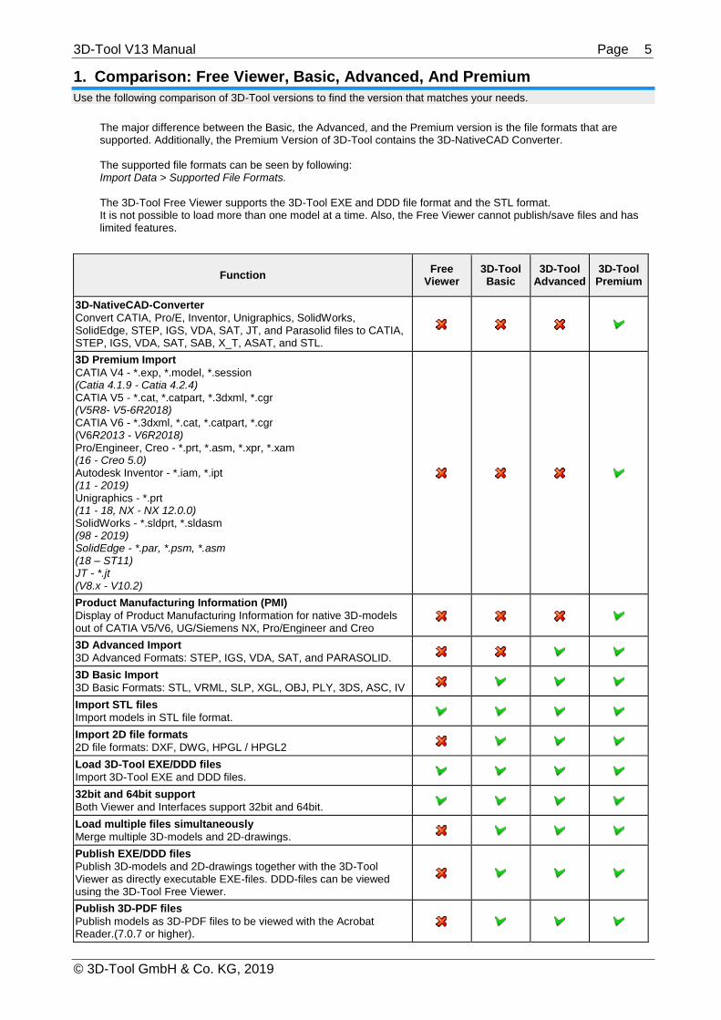
1. Comparison: Free Viewer, Basic, Advanced, And Premium Use the following comparison of 3D-Tool versions to find the version that matches your needs.
The major difference between the Basic, the Advanced, and the Premium version is the file formats that are supported. Additionally, the Premium Version of 3D-Tool contains the 3D-NativeCAD Converter. The supported file formats can be seen by following: Import Data > Supported File Formats. The 3D-Tool Free Viewer supports the 3D-Tool EXE and DDD file format and the STL format. It is not possible to load more than one model at a time. Also, the Free Viewer cannot publish/save files and has limited features.
Function Free
Viewer 3D-Tool Basic
3D-Tool Advanced
3D-Tool Premium
3D-NativeCAD-Converter
Convert CATIA, Pro/E, Inventor, Unigraphics, SolidWorks, SolidEdge, STEP, IGS, VDA, SAT, JT, and Parasolid files to CATIA, STEP, IGS, VDA, SAT, SAB, X_T, ASAT, and STL.
3D Premium Import
CATIA V4 - *.exp, *.model, *.session (Catia 4.1.9 - Catia 4.2.4) CATIA V5 - *.cat, *.catpart, *.3dxml, *.cgr (V5R8- V5-6R2018) CATIA V6 - *.3dxml, *.cat, *.catpart, *.cgr (V6R2013 - V6R2018) Pro/Engineer, Creo - *.prt, *.asm, *.xpr, *.xam (16 - Creo 5.0) Autodesk Inventor - *.iam, *.ipt (11 - 2019) Unigraphics - *.prt (11 - 18, NX - NX 12.0.0) SolidWorks - *.sldprt, *.sldasm (98 - 2019) SolidEdge - *.par, *.psm, *.asm (18 – ST11) JT - *.jt (V8.x - V10.2)
Product Manufacturing Information (PMI)
Display of Product Manufacturing Information for native 3D-models out of CATIA V5/V6, UG/Siemens NX, Pro/Engineer and Creo
3D Advanced Import
3D Advanced Formats: STEP, IGS, VDA, SAT, and PARASOLID.
3D Basic Import
3D Basic Formats: STL, VRML, SLP, XGL, OBJ, PLY, 3DS, ASC, IV
Import STL files
Import models in STL file format.
Import 2D file formats
2D file formats: DXF, DWG, HPGL / HPGL2
Load 3D-Tool EXE/DDD files
Import 3D-Tool EXE and DDD files.
32bit and 64bit support
Both Viewer and Interfaces support 32bit and 64bit.
Load multiple files simultaneously
Merge multiple 3D-models and 2D-drawings.
Publish EXE/DDD files
Publish 3D-models and 2D-drawings together with the 3D-Tool Viewer as directly executable EXE-files. DDD-files can be viewed using the 3D-Tool Free Viewer.
Publish 3D-PDF files
Publish models as 3D-PDF files to be viewed with the Acrobat Reader.(7.0.7 or higher).

3D-Tool V13 Manual Page 6
© 3D-Tool GmbH & Co. KG, 2019
Save STL, VRML, 3DS, PLY, OBJ and U3D
Export the models from the 3D-Tool Viewer as faceted data (meshes) into STL, VRML, 3DS, PLY, OBJ, or U3D files.
Support of 3D mouses
Use 3Dconnexion 3D mouses e.g. SpaceNavigator, SpaceExplorer, SpacePilot, SpaceTraveller
Print any 3D and 2D view or a combination of views.
Create PNG/BMP/JPG pictures
Save any 3D or 2D view or a combination of views as PNG, BMP or JPG file.
Capture to clipboard
Select and copy a section of the screen to the Clipboard.
Hide and show parts
Hide and show parts, assemblies, and models.
Change the display of parts
Change the color of parts and assemblies, switch them transparent, and show them in different render modes, e.g. shaded, shaded with edges, hidden lines.
Custom Views
Save any 3D or 2D view as Custom View. Custom Views contain the state and orientation of the model as well as all display settings.
Cross sections
Create cross sections of the model, its assemblies, and parts. Save the cross section line to a DXF-file.
3D annotations and dimensions
Measure distances, angles, radii, wall thickness, and clearances, or make annotations.
2D markups and dimensions
Measure distances, angles, radii, add redline markups, and insert text and pictures.
Assembly explode
Create exploded views of the model.
Animation
Combine Custom Views to animations.
Animation export as AVI video
Export 3D-Tool animations as AVI video.
Model compare
Graphically highlight the differences between two models.
Tooling analysis
Display cavities, draft angles and undercuts and calculate the projected area.
Wall thickness analysis
Calculate and display the wall thicknesses of a model.
Model-Info
Display the volume, the surface area, the dimensions, and the weight of models and parts.
Position and copy parts
Move, rotate, mirror, scale, and copy parts.
Property Editor
Change names, colors, and transparencies of parts and assemblies.
Custom View Editor
Change the order and the names of Custom Views.
Placement
Position and align parts.
Repair
Delete faces, reposition flipped faces, and connect open edges.
RP-Layout
Place parts on a Rapid Prototyping System platform.

3D-Tool V13 Manual Page 7
© 3D-Tool GmbH & Co. KG, 2019
2. Hardware And Software Requirements Consider the following hardware and software requirements when you install 3D-Tool.
Hardware Requirements
We recommend a Desktop-PC, Laptop, or Tablet with a standard processor, at least4GB of RAM, and a screen resolution of 1024 x 768 pixels or more. For bigger and more complex CAD models, we recomend a graphics card which supports OpenGL 3.3 or higher.
The opening and coversion speed of CAD files when using the 3D-Tool Advanced and Premium interfaces depend on the processor speed and the amount of RAM available. With increasing size CAD models require more computing power and main memory. For big and complex CAD models we recommend a fast up-to-date processor and 8GB of RAM or more.
Tip
To increase the display speed of the models, try the OpenGL hardware acceleration. The hardware acceleration is activated in the Preferences group of the Options tab. After a warning has appeared the hardware acceleration is active and the model should move smoother. If there are no problems, it can be set permanently through Options tab > Preferences group > Preferences button > Hardware. When the hardware acceleration is enabled, the OpenGL 3.3 hardware acceleration of the graphics card can also be activated to optimize the display performance.
Software Requirements
Supported Operating Systems
3D-Tool Basic / Advanced 3D-Tool Premium
Windows Vista (32/64bit) Windows 7 (32/64bit) Windows 8 / 8.1 (32/64bit) Windows 10 (32/64bit)
Windows 7 (32/64bit) Windows 8.1 (32/64bit) Windows 10 (64bit*)
Software Requirements to use the Premium Import
The following software will be installed together with 3D-Tool as it is required for the Premium Import:
Microsoft Visual C++2015 [x86/x64] Redistributable
64bit Support
3D-Tool is a 32bit and 64bit software. The 64bit version of the program is supported by Windows 7 x64; Windows 8 x64, and Windows 10 x64.
* Premium Interfaces Under Windows 10 x86 (32bit)
We intensively tested the Premium interfaces under Windows 10 x86 and have not found any noticeable problems. But the interface supplier does not offer support for Windows 10 x86, so we cannot officially release 3D-Tool Premium for Windows 10 x86.

3D-Tool V13 Manual Page 8
© 3D-Tool GmbH & Co. KG, 2019
3. Activation and Licensing Run 3D-Tool and use the 3D-Tool license dialog to activate a 3D-Tool License, request a Trial License, or start 3D-Tool as Free Viewer.
Run as Free Viewer
Without a valid License Key or Trial Key, 3D-Tool can only be used as Free Viewer with limited features.
Note
The Free Viewer can be downloaded separately from our website: www.3D-Tool.de. The Free Viewer can be used to view the small, easily sent 3D-Tool DDD files.
License Activation
Request a License Key
For each license you order, you will receive a License Certificate with an Authorization Key on it. After starting 3D-Tool, click Get License Key in the license dialog and enter your Authorization Key. Next, enter the e-mail address to which you want the License Key to be sent. 3D-Tool will connect to the 3D-Tool website, your license data will be checked, and within 60 minutes you will receive the License Key by e-mail. Requesting a License Key this way requires an active Internet connection. If your computer does not have an Internet connection or the connection fails, you can obtain a License Key by e-mail to [email protected] or by fax. To do so, please provide the following:
The Registration-ID from the 3D-Tool license dialog.
The Authorization Key from the 3D-Tool License Certificate.
The e-email address to which you want the License Key to be sent.
The processing of a request by e-mail can take up to two business days
Activation with the 3D-Tool License File
The e-mail with the Licensing Key has a license file (license.dat) attached. Saving this license file in the 3D-Tool installation directory, will make 3D-Tool available to all user accounts on the computer.
Activation with the License Key
After receiving the License Key, enter it in the license dialog, and click on Activate Key. Now 3D-Tool can be used. You must enter the License Key separately for each user account on the computer.
Note
A 3D-Tool Single User License may only be used on a single computer. A License Key will work only on the computer for which it was requested. If the computer is replaced or newly setup, you have to request a new License Key. The previous 3D-Tool installation may not be used any more and has to be deleted or uninstalled.

3D-Tool V13 Manual Page 9
© 3D-Tool GmbH & Co. KG, 2019
Reactivation After Changing Computers
If you replace the computer or newly install the operating system, you have to request a new License Key. See License Activation above for further instructions.
Activating an Upgrade
If you have ordered an upgrade and received the new License Certificate run 3D-Tool, select the Options tab and click Licensing in the Licensing group. The 3D-Tool license dialog is displayed. See License Activation above for further instructions.
Activating an Update
After you have ordered an update and received the new License Certificate, download and install the newest version of 3D-Tool from our website www.3D-Tool.com. See License Activation above for further instructions.
14 Day Trial License
Obtaining a Trial Key
To try all features of 3D-Tool, a 14 Day Trial License can be requested once. Run 3D-Tool and click Get Trial Key in the licensing dialog. Next enter your e-mail address and contact information, and click Get key. 3D-Tool will
connect to the 3D-Tool website, your request will be checked, and within 60 minutes you will receive the Trial Key by e-mail. If your computer does not have a connection to the internet or the connection fails, you can obtain a Trial Key by e-mail or fax. To do so, please, provide the following information:
The Registration-ID from the license dialog.
The e-mail address to which you want the Trial Key to be sent.
Your contact information (company, address, and contact person).
Note
The Trial Key will only work on the computer for which it was requested. Only one Trial Key can be requested online. If you need further Trial Keys, please send us an e-mail.
Activating the Trial Key
After receiving the Trial key, enter it in the license dialog and click on Activate Key to activate 3D-Tool for the 14 day trial period. To start, select a license for the current session: Basic, Advanced, or Premium. Only the

3D-Tool V13 Manual Page 10
© 3D-Tool GmbH & Co. KG, 2019
respective features and interfaces will by available during the session. That way you can try the 3D-Tool version you intend to buy.
Note
The 3D-NativeCAD Converter is a discrete application and will work regardless of the license selected for a 3D-Tool session.

3D-Tool V13 Manual Page 11
© 3D-Tool GmbH & Co. KG, 2019
4. File Formats and Limitations This section informs you about the file formats supported by 3D-Tool and about the limitations when viewing and converting the files.
Supported File Formats
Find out which file formats can be opened and saved in the different 3D-Tool versions.
Load
3D-Formats Free
Viewer 3D-Tool Basic
3D-Tool Advanced
3D-Tool Premium
NativeCAD Converter*
CATIA V6, V6R2013 - V6R2018, PMI display
(*.3dxml, *.CATPart, *.CATProduct, *.cgr)
CATIA V5, V5R8 - V5-6R2018
(*.CATPart, *.CATProduct, *.cgr, *.3dxml)
CATIA V4, 4.1.9 - 4.2.4
(*.model, *.exp, *.session)
Pro/E, CREO, 16 - Creo 5.0, PMI display
(*.prt, *.prt.*, *.asm, *.asm.*, *.xpr, *.xas)
Autodesk Inventor, V6 - 2019
(*.ipt off V6, *.iam off 11)
SolidWorks, 98 - 2019, SW2015 and newer require 3D-
Tool 64bit (*.sldprt, *.sldasm)
SolidEdge files, 18 – ST11
(*.par, *.psm, *.asm)
UG/Siemens NX, 11 - NX12.0.0, PMI display
(*.prt)
JT, V8.x - V10.2
(*.jt)
Parasolid files (*.x_t *.x_b)
STEP files (*.stp)
IGS files (*.igs)
VDA files (*.vda)
SAT files (*.sat, ASIC-Text)
SAB files (*.sab, ASIC-Binary)
STL files (*.stl)
VRML1, VRML2 files (*.wrl)
Render files (*.slp)
PLY files (*.ply)
XGL files (*.xgl *.zgl)
OBJ files (*.obj)
3DS files (*.3ds *.prj *.pli)
ASC files (*.asc)
Inventor files (*.iv)

3D-Tool V13 Manual Page 12
© 3D-Tool GmbH & Co. KG, 2019
3D-Tool files (*.ddd)
3D-Tool EXE files (*.exe)
2D-Formats Free
Viewer 3D-Tool Basic
3D-Tool Advanced
3D-Tool Premium
NativeCAD Converter*
DXF files (*.dxf)
DWG files, up to AutoCAD 2015 (*.dwg)
HPGL files (*.plt *.plo *.hpg *.hp2)
* The 3D-NativeCAD Converter is part of 3D-Tool Premium.
Note
HPGL/HPGL2 files can be created on any computer by printing with a HPGL compatible print driver.
Save
Formats Free
Viewer 3D-Tool Basic
3D-Tool Advanced
3D-Tool Premium
NativeCAD Converter*
3D-Tool EXE-files (*.exe)
Viewer + 3D-models + 2D-drawing + Annotations + Dimensions + Custom Views + Animations
3D-Tool files (*.ddd)
3D-models + 2D-drawing + Annotations + Dimensions + Custom Views + Animations
3D-PDF files (*.pdf)
triangulated 3D-models
CATIA V5 files, V5R15 - V5-6R2018
(*.catpart, *.catproduct) 3D-Catia V5 models
CATIA V4 files (*.model, *.exp)
3D-Catia V4 models
STEP files (*.stp)
3D-STEP models
IGS files (*.igs)
3D-IGES models
VDA files (*.vda)
3D-VDA models
SAT, SAB files, V7, V8, V10 – R2019 (*.sat)
V18 – R2019 (*.sab) 3D-SAT models (ASIC-Text, ASIC-Binary)
Parasolid file, V12 – V31 (*.x_t)
3D-Parasolid models (Parasolid-Text)
STL files (*.stl)
triangulated 3D-models
VRML 2.0 files (*.wrl)
triangulated 3D-models
PLY files (*.ply)
triangulated 3D-models
OBJ files (*.obj)
triangulated 3D-models
3DS files (*.3ds)
triangulated 3D-models
U3D files (*.u3d)
triangulated 3D-models
* The 3D-NativeCAD Converter is part of 3D-Tool Premium.
3D-Tool V13 Manual Page 13
© 3D-Tool GmbH & Co. KG, 2019
Limitations
Consider the following limitations when opening files with the 3D-Tool Viewer or converting files with the 3D-NativeCAD Converter.
Common File Limitation
Due to the complexity of CAD files and despite intense testing some files may fail to open/convert completely or partially.
Limitions of 3D-Tool Viewer Functions
Common
Free Points
Free points in 3D-models are not supported by the Viewer.
Tools and Functions
Accuracy of measurement and analysis
3D-CAD files will be triangulated during their import into 3D-Tool, which means they are broken down into triangles. Depending on the quality of the triangulation some imprecision may appear when measuring and analyzing the 3D models.
Tooling Analysis
The projected area of a model is calculated using a graphical projection which could cause some imprecision.
Wall Thickness Analysis
The calculation of wall thicknesses is computationally intensive and can take hours for big models and high quality analysis settings. Open edges and flipped surfaces may distort the results of the analysis.
Model Compare
The 3D-Tool Model Compare is a graphical/visual comparison by dyeing the models in different colors and then superimposing them. Differences located inside the models can only seen by using cross section or by hiding parts.
Information Tool
Information on volume and weight is only accurate for closed parts of models. Open edges and flipped surfaces distort the volume calculation and may lead to wrong results. IGES files are especially susceptible to this.
Repair Tool
The automatic repair cannot always completely close models with open edges or flipped surfaces. To get a "watertight" model more or less extensive manual repairs are needed.
Limited Touch-Screen/ Tablet-PC support
Some 3D-Tool functions use mouse-over/hover effects. Not all mouse-over effects are available on a touch-screen. The usability of these functions may be limited by the inaccuracy of the touch points.
Publish and Save
No downward compatibility of 3D-Tool files
3D-Tool EXE and DDD files published by a particlular major version of 3D-Tool can only be opened by 3D-Tool or the 3D-Tool FreeViewer in this or a newer major version.
Publish 3D-PDF
When publishing 3D-PDF files the geometry and structure of the 3D models will be published but not the notices, dimensions, Custom Views or animations created with 3D-Tool.
Save STL files
To ease the editing of STL files, the "Save" function will automatically and without warning update open STL files with the state present in 3D-tool. To avoid the automatic update of existing STL files, the "Save as …" function must be used.
Limitations of the 3D-Premium Import
The following limitations apply to CATIA, Pro/E Creo, Inventor, SolidWorks, SolidEdge, UG/NX, STEP, IGES, VDA, SAT, JT and Parasolid files during the Premium-Import into the 3D-Tool Viewer and during conversion using the 3D-NativeCAD Converter.
Common
Assembly attributes
Attributes assigned on the assembly level are not read by the viewer or the converter, for example colors assigned on the assembly level are lost and elements hidden on the assembly level will be loaded.
Assembly features
Features (e.g. cuts, bodies, holes) added on the assembly level are not supported and will be ignored by the viewer or the converter. The support of patterns added on the assembly level is limited in the viewer or the

3D-Tool V13 Manual Page 14
© 3D-Tool GmbH & Co. KG, 2019
converter.
Properties and attributes
The viewer and the converter have limited support of common properties such as Color and Name. Further properties (e.g. material properties, user defined properties) are not supported by the viewer or the converter.
Product Manufacturing Information
The viewer widely supports the display of most PMI data for models out of CATIA V5/V6, Pro/Engineer, Creo and Siemens/UG NX. Limitations of PMI display can be found in the file format specific limitations. The converter does not support the conversion of PMI data, not even to output formats that support PMI.
2D-data / 2d-sketches
2D-data and 2D-sketches are not supported by the viewer or the converter.
Layers
Layers are not displayed in the viewer. In the converter the translation of layer information is limited.
Free parts, faces, and curves
The converter supports free parts, faces, and curves only on the top assembly level and not within sub-assemblies.
Axes, planes, and local coordinate systems
The support of axes, planes, and local coordinate systems is limited in the converter.
User-defined views
User-defined views and component views are not supported by the viewer or the converter.
Graphical data (visualization data)
The converter does not support graphical visualization data that is contained in 3D-CAD files in addition to the CAD/BREP-data. The viewer supports the display of this graphical data when the import settings are set to "CAD - graphical data". The viewer will always read the highest level of display (LOD) from the part level. Graphical data from the assembly level is not supported by the viewer. The support of curves in graphical data is limited. In the Viewer the colors of graphical data may differ from the original.
Embedded triangulated data
Triangulated data embedded in 3D CAD files is not supported by the converter. The viewer will only read embedded triangulated data when using the import setting "CAD - graphical data".
Suppressed elements
Suppressed element will not be read by the viewer and the converter, not even by activating the "Load hidden elements" or "Convert hidden elements" option.
Hidden elements
Hidden elements will be read by the viewer and the converter when the "Load hidden elements" or "Convert hidden elements" option is activated. If these hidden elements are converted to file formats that do not support hidden elements (e.g. STEP) the hidden elements will be visible.
CATIA V5 / V6
The converter does not support 3DXML files. The viewer will read 3DXML files featuring static tessellation. XML tessellation as well as XML files in Authoring Mode are not supported by the viewer.
CGR files can be displayed in the viewer but are not supported by the converter.
All parts and sub-assemblies of an assembly file (*.CATProduct) have to be in the folder of the assembly file or its sub-folders otherwise they will not be read by the viewer or the converter.
File names may only contain ASCII characters. During the conversion to CATIA V5, all non ASCII characters in file and part names will be replaced by an underscore. Additionally, in part names the characters ! : / \\ will be replaced by an underscore.
The viewer and the converter require a complete file path to read and write CATIA V5 files in batch mode.
During the conversion to CATIA V5 the attributes line-type and line-thickness will be translated only for free wires and curves but not for edges.
The viewer does not support the display of PMI data without geometry references, for hole features in user defined patterns or for hole features on the assembly level.
The viewer does not support the display of PMI-data from 3DXML files.
CATPart files created using the geometry scale "Small Scale" or "Big Scale" are not supported by the viewer.
Due to hardware requirements, it may not be possible to view or to convert CATIA V5 files when using an older computer (approx. before 2003). If you plan to use the CATIA V5 import on such a system, request a free Trial Key to test the import.
STEP
The viewer supports PMI-data only for STEP AP242 and only from graphical CAD data (visualization data).
The viewer does not support monolithic STEP assembly files, which contain only graphical CAD data.
IGES
Binary and compressed IGES files are not supported by the viewer or the converter.
IGES files often do not contain information on face normals (inside/outside). This may lead to flipped surfaces when IGES files are imported into 3D-Tool. That means the inside of surfaces is turned outside which can have a negative effect especially on volume calculation but also on all other analysis of the model.
3D-Tool V13 Manual Page 15
© 3D-Tool GmbH & Co. KG, 2019
Inventor
All parts and sub-assemblies of an assembly file (*.iam) have to be in the same folder otherwise they will not be read by the viewer or the converter.
Attributes, such as color and layer, are not read by the viewer or the converter.
Some special Inventor features, such as "Lofting" and "Weld Symbols", are not supported by the viewer or the converter.
Free form surfaces (T-splines) are not supported by the viewer and the converter.
Sheet metal bodies are not supported by the viewer and the converter prior to Inventor version 11.
JT
The viewer and the converter only support versions 8.x, 9.x and 10.x.
"Big Endian" files are not supported by the viewer or the converter.
The Name and Layer attributes are not supported by the viewer or the converter. The support of the Color attribute is limited.
Free points are not supported by the converter.
Free curves within graphical data are not supported by the viewer.
Pro/Engineer, Creo
All parts and sub-assemblies of an assembly file (*.asm) have to be in the same folder otherwise they will not be read by the viewer or the converter.
The Viewer and the Converter do not support Simplified Representations at part level.
Instances in family tables are read by the viewer or the converter only if the corresponding XPR and XAS files are present, even though these are only optional in Pro/E. Without the XPR and XAS files always the generic parts are read.
The converter translates local coordinate systems only to file formats that support assemblies (CATIA V5, STEP, IGES, ASAT).
The curves "using equation" and "local push" are not supported by the viewer or the converter.
Cosmetic features are not supported by the viewer or the converter.
The viewer supports product manufacturing information (PMI) starting with Pro/Engineer WF3. There is no support of PMI without geometry reference, PMI text attributes (e.g. font and color), PMI set to “Remove from State”, unicode text, or manually overwritten dimension values. There is only limited support of PMI based on 3D-dimensions, for hole features and patterns, as well as for combined geometric tolerances.
Hidden "merge features" may not be read correctly by the viewer or the converter.
The viewer and the converter do not support flexible assemblies. Thus, positioning and/or sizing of these components might be incorrect.
In certain complex BREP scenarios the viewer and the converter may not show the expected results for bodies with multiple lumps or for lumps with multiple shells.
SolidEdge
All parts and sub-assemblies of an assembly file (*.asm) have to be in the folder of the assembly file or its sub-folders otherwise they will not be read by the viewer or the converter.
Coordinate systems (WCS) are not supported by the converter.
Simplified views will not be read by the viewer or the converter.
SolidEdge sub-assemblies can have multiple family tables. In the root assembly one can select one of the tables for each instance of the sub-assembly. The viewer and the converter do not support this, so that the instances may have unwanted or wrongly transformed parts.
SolidWorks
All parts and sub-assemblies of an assembly file (*.sldasm) have to be in the folder of the assembly file or its sub-folders otherwise they will not be read by the viewer or the converter.
Colors are supported by the viewer or the converter starting with SolidWorks 2004.
Colors assigned to instances of parts and assemblies are not read by the viewer or the converter.
The units of a model are read by the viewer or the converter starting with SolidWorks 2001. With earlier versions the units are always assumed to be meters. This also applies to unsupported units such as feet and inches.
Hidden bodies and features within parts are not supported by the viewer or the converter.
The attributes "Show", "No-show" and "Hidden" will be read by the viewer or the converter starting with SolidWorks 2004.
Hidden elements are supported by the Viewer and the Converter starting with SolidWorks 2009.
Configurations are supported starting with SolidWorks 98. In order to display and convert a part within an assembly in its correct configuration, the according configuration must be saved in the part file. This is not necessarily the case, especially not, if older parts have been opened and saved with a newer version of SolidWorks. If configurations are missing, open the part in Solidworks, activate each configuration, and save the part. Faulty or missing part configurations within SolidWorks assemblies may cause the viewer and the converter to read the assembly only partially or not at all. The graphical data within SolidWorks files does not

3D-Tool V13 Manual Page 16
© 3D-Tool GmbH & Co. KG, 2019
provide configurations, thus when selecting a configuration for import into the viewer the viewer will always read the CAD/BREP-data even if the import settings are set to "CAD - graphical data".
Coordinate systems, work planes, free curves, and free points are not supported by the converter.
Curves within graphical CAD data are not supported by the viewer.
Only CAD-models out of SolidWorks major versions will be supported by the viewer and the converter. Alpha and beta versions cannot be read.
SolidWorks 2015 and newer are only supported by the 64bit versions of the viewer and the converter.
Unicode text is only supported from the "Basic Multilingual Plane" (Plane 0, BMP). File names from the "Supplementary Ideographic Plane" (SIP) are not supported by the viewer or the converter.
UG / Siemens NX
All parts and sub-assemblies of an assembly file (*.prt) have to be in the folder of the assembly file or its sub-folders otherwise they will not be read by the viewer or the converter.
2D-drawing included in a 3D-model will not be identified as a 2D-drawing by the viewer and will be partly loaded as 3D curve elements together with the 3D-model.
For body cuts the viewer and the converter do not distinguish between the cutting tool body and the body to be cut. Both will be loaded and converted as bodies.
Product manufacturing information (PMI) from Siemens NX10 models is not yet supported by the viewer or the converter. PMI without geometry reference is not supported as well as PMI text attributes (e.g. font and color).
The viewer does not support Product manufacturing information (PMI) prior to NX6. PMI without geometry reference is not supported. PMI text attributes (e.g. font and color) are not supported. PMI associated with datum plane, datum axis and Annular Region is not supported.
PMI in graphical CAD data (visualization data) is always loaded, even if they are hidden. Graphical PMI marked as “Assorted Parts” is not supported.
Parasolid X_T
The converter creates an empty Parasolid body for various types of elements such as material properties, axis systems and user defined attributes. Some applications based on the Parasolid kernel have issues while opening such files. This is not a limitation and we suggest that you contact the support for that particular Parasolid-based application.
VDA
Errors can occur when reading VDA files with the viewer or the converter, especially if the accuracy of the VDA data is insufficient. If such errors occur, as much data as possible is read.
Limitations of the 3D-Advanced Import
The following limitations apply when opening models using the Advance interfaces.
Open Edges
The Advanced-Import does not provide Healing for the generation of "watertight" models. Due to the triangulation of the models during import generally there will be some open edges, in rare cases there can be missing surfaces.
STEP AP242
The Advanced-Import does not support graphical visualization data from STEP (STEP AP242). Files containing only visualization data cannot be opened. From files containing both, visualization and CAD data, only the CAD data will be loaded.
IGES
IGES files often do not contain information on face normals (inside/outside). This may lead to flipped surfaces when IGES files are imported into 3D-Tool. That means the inside of surfaces is turned outside which can have a negative effect especially on volume calculation but also on all other analysis of the model.
Limitations of the 3D-Basic Import
The following limitations apply when opening models using the Basic interfaces.
VRML
The viewer will only load triangulated data (IndexedFaceSets) from VRML files. The viewer has only limited support of transformations.
OpenInventor 2.0
The viewer will only load triangulated data (IndexedFaceSets) from OpenInventor 2.0 files. The viewer has only limited support of transformations.

3D-Tool V13 Manual Page 17
© 3D-Tool GmbH & Co. KG, 2019
Limitations of the 2D-Import
The following limitations apply to DXF, DWG, and HPGL files when loaded into the 3D-Tool Viewer.
Embedded pictures
The display of embedded pictures in the viewer is limited.
Filled polylines
Filled polylines (Trace entities) are not supported by the viewer. AEC Objects
AEC (Architecture, Engineering, and Construction) objects are not supported by the viewer.
3D-Tool V13 Manual Page 18
© 3D-Tool GmbH & Co. KG, 2019
5. Mouse, Keyboard Controls And Touch Gestures This chapter explains how to use 3D-Tool using the mouse, the keyboard and touchschreens.
3D Mouse
Use the 3Dconnexion 3D-mouses to move, rotate, and zoom the model in the view.
Supported 3Dconnexion mouses
3D-Tool supports these 3D-mouses made by 3Dconnexion:
SpaceNavigator
SpaceExplorer
SpacePilot
SpaceTraveller
SpaceMouse Wireless
SpaceMouse Pro USB/Wireless
SpaceMouse Plus USB
SpaceBall 5000 USB
The mouse buttons are set to Fit to screen. You can adjust the speed and the assignment of the axes in the 3Dconnexion control panel.
Note
In case a supported mouse is not recognized, try updating the 3Dconnexion driver.
Limitations
The following 3D-mouses are not supported by newer 3Dconnexion drivers and thus are not supported by 3D-Tool:
SpaceMouse Plus Serial
SpaceMouse Classic USB
SpaceMouse Classic Serial
SpaceBall 5000 Serial
SpaceBall 4000
CadMan
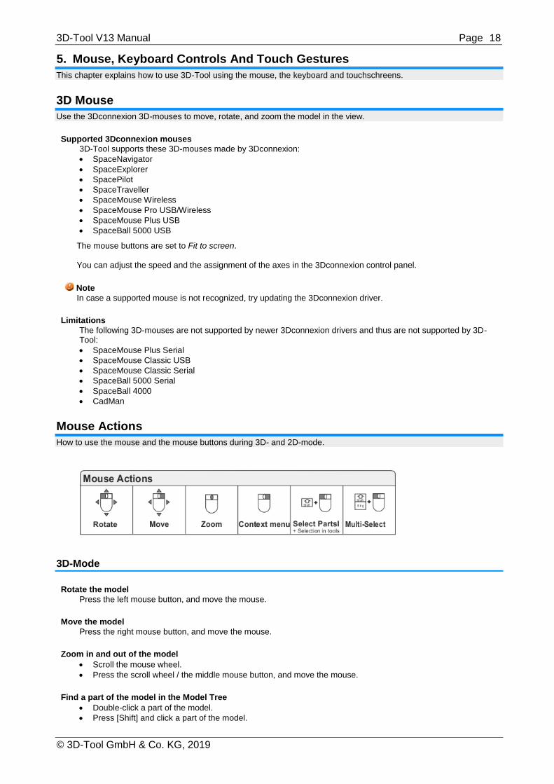
Mouse Actions
How to use the mouse and the mouse buttons during 3D- and 2D-mode.
3D-Mode
Rotate the model
Press the left mouse button, and move the mouse.
Move the model
Press the right mouse button, and move the mouse.
Zoom in and out of the model
Scroll the mouse wheel.
Press the scroll wheel / the middle mouse button, and move the mouse.
Find a part of the model in the Model Tree
Double-click a part of the model.
Press [Shift] and click a part of the model.
3D-Tool V13 Manual Page 19
© 3D-Tool GmbH & Co. KG, 2019
Access frequently needed functions
Right-click a part of the model.
Right-click parts, assemblies, and models in the Model Tree.
Show hidden parts
Right-click into the background of the model.
Fit assemblies and parts to the display
Double-click assemblies and parts in the Model Tree.
Select multiple parts on the model
Double-click the first part, press [Shift] and [Ctrl], and click more parts.
Tip
To highlight the selected parts and assemblies in red, activate Highlight Selection in 3D-Mode in the Model Tree group.
Activate a model
Double-click the model in the Model Tree
Measure/Markup tool
Move a dimension/annotation by pressing the left mouse button.
Right-click a dimension/annotation to change its properties.
Explode tool > Manual Explode Functions
Double-click an exploded part to reset it.
Tooling Analysis tool
To pick a custom reference plane, press [Shift], and click on the model.
Painter and Repair tool
To choose triangles, planes and surfaces, press [Shift], and click on the model.
2D Mode
Move the drawing
Press the right mouse button, and move the mouse.
Zoom in and out on the drawing
Scroll the mouse wheel.
Annotate mode
Move a dimension/markup by pressing the left mouse button.
Double-click a dimension/markup to change its properties.
Right-click a dimension/markup to call-up frequent functions.
To scale a markup, press [Ctrl], and scale the markup by pressing the left mouse button.
2D-Tool mode
To select an element of the drawing or a 3D-Tool dimension/markup, hold down [Shift], and click on the element.
To select multiple elements, hold down the [Shift] and marquee select the elements while pressing the left-mouse button.

3D-Tool V13 Manual Page 20
© 3D-Tool GmbH & Co. KG, 2019
Touch Gestures
3D-Tool supports touchscreens. Additionally, special controls were added for some features to increase the usability with touchscreens.
3D-Mode
Rotate the model
Move your finger in the screen in the direction that the model should be rotated.
Move the model
Touch two points of the screen, and then move your fingers in the direction that the model should be moved.
Zoom in and out of the model
Touch two points of the screen, and then move your fingers towards each other, to zoom in. To zoom out, touch two points of the view, and then move your fingers away from each other.
Find a part of the model in the Model Tree
Double-tap a part of the model.
Access frequently needed functions
Press your finger on a part of the model for approximately one second, and then release it.
Press your finger on parts, assemblies, and models in the Model Tree for approximately one second, and then release it.
Show hidden parts
Press your finger into the background of the model for approximately one second, and then release it.
Fit assemblies and parts to the screen
Double-tap assemblies and parts in the Model Tree.
Activate a model
Double-tap the model in the Model Tree
Measure/Markup tool
Select references for dimension/annotation by briefly tapping on the model, and confirm the selection each
time with . Possible references will be shown in light blue
Move a dimension/annotation by briefly tapping it, and then dragging it in the screen.
Press your finger on a dimension/annotation for approximately one second, and then release it to change its properties.
Explode tool > Manual Explode Functions
To reset exploded parts, double-tap on the exploded part.
2D Mode
Move the drawing
Touch and drag your finger in the view.

3D-Tool V13 Manual Page 21
© 3D-Tool GmbH & Co. KG, 2019
Zoom in and out on the drawing
To zoom in, touch two points of the screen, and then move your fingers towards each other. To zoom in. To zoom out, touch two points of the view, and then move your fingers away from each other.
Annotate mode
Double-tap a dimension/markup to change its properties.
Press your finger on a dimension/markup for approximately one second, and then release it to call-up frequent functions.
Limitations
Some 3D-Tool functions use mouse-over/hover effects. Not all mouse-over effects are available on touchscreen. The usability of these functions may be more or less limited by the inaccuracy of the touch points.
Context Menu
Use the context menu to quickly access frequently needed functions. In a lot of cases, this eases working with the different objects.
Open the context menu by right-clicking:
On models, assemblies, or parts in the Model Tree.
On the parts of a model in the display.
In 3D-mode in the background if parts are hidden or you are in full screen mode.
In the 3D-tool Measure and Markup on the textboxes of annotations and dimensions.
In 2D-Mode under Annotate on redline markups and 2D dimensions.
Some features can only be accessed through the context menu.
Note
Using touch gestures, the context menu opens by pressing the finger about one second on the object and then release it.
Example
When displaying cross sections, parts of the model can be excluded from the cross section by selecting Cross section on/off from the context menu.
Tip
The context menu makes full screen presentations easier because the most important menu items, as well as default and customs views, can be accessed.
Function Keys
Use the function keys to quickly access certain functions.
[ESC] Stop an animation or a Custom View Show. Exit the full screen mode. Abort the file import (if possible) Abort the calculation in the Wall Thickness Analysis tool.
Abort the creation of annotations and dimensions.
[DEL]
Delete the assemblies and parts selected in the Model Tree. Delete the selected 3D/2D dimension or annotation.
[F1]
Open the Help.
[F2]
Zoom in.
[F3]
Zoom out.

3D-Tool V13 Manual Page 22
© 3D-Tool GmbH & Co. KG, 2019
[F4]
Fit to screen.
[F5]
Previous view
[F9]
Load view.
[F10]
Save view.
[Ctrl] + F
Search in the Model Tree.

3D-Tool V13 Manual Page 23
© 3D-Tool GmbH & Co. KG, 2019
6. Open models and drawings This chapter shows how to open 3D models and 2D drawings with the 3D-Tool Viewer.
Open models and drawings
You can load multiple models and drawings in one session or load each file individually in a separate 3D-Tool window.
Open 3D models
Open within 3D-Tool
Start 3D-Tool, and use the Open function in the File tab or click Open in the Quick Access Toolbar. Then select the file(s) with the File open dialog, and click Open.
Open with the Windows Explorer
Via Double-click: 3D files that are supported by your 3D-Tool version can be opened by double-clicking
them in the Windows Explorer. 3D-Tool starts automatically and opens the file.
Via Drag'n Drop: Start 3D-Tool, and drag the files from the Windows Explorer into the 3D-Tool window.
Import Settings
3D-CAD files are triangulated during their import into 3D-Tool. For graphical display the 3D-models are divided into a mesh of numerous little triangles. To do so, the Import Settings dialog is displayed when opening the following files:
STEP, IGS, VDA, SAT, PARASOLID and JT files
Native files of CATIA V4/V5, Pro/Engineer, Creo, Autodesk Inventor, Solidworks, SolidEdge and UG/Siemens NX.
For details on the Import Settings see chapter Advanced/Premium Import Settings.
Combining multiple models
You can combine multiple models in one scene. Simply open the desired models via Open or via Drag'n Drop.
Tip
The 3D files will be put into the scene according to their coordinate systems. If a model is not positioned correctly, it can be repositioned with the Placement, Move, or Rotate tool.
Note
Loading multiple files is not supported by the 3D-Tool Free Viewer.
Load 2D Drawings
Load within 3D-Tool
Start 3D-Tool, and use Open function in the File tab or click Open in the Quick Access Toolbar. Then select the file(s) with the File open dialog, and click Open.
Load with the Windows Explorer
Via Double-click: 3D files that are supported by your 3D-Tool version can be opened by double-clicking
them in the Windows Explorer. 3D-Tool starts automatically and opens the file.
Via Drag'n Drop: Start 3D-Tool, and drag the files from the Windows Explorer into the 3D-Tool window.
Combining multiple drawings
You can combine multiple models in the display. Simply open the desired drawings via Open or via Drag'n Drop. After the first drawing is loaded, the Load Position of 2D File dialog will be displayed offering the following options:
Replace current data
The new drawing replaces all currently loaded drawings.
Add at original position
The new drawing will be added at its original position. This may cause the new drawing to be placed over drawings that are already displayed.
Add right of drawing
The new drawing will be added to the right of the existing drawing.
Add top of drawing
The new drawing will be added on top of the existing drawing

3D-Tool V13 Manual Page 24
© 3D-Tool GmbH & Co. KG, 2019
Abort
The new drawing will not be loaded.
Load DWG-files with multiple Layouts
DWG-files can contain multiple so called layouts. When opening them, a dialog appears for selecting the layout to be loaded. The default layout is the one that was active during the generation of the DWG.
Load all pages: Loads the DWG model and all layouts side by side in the view.
Model: Loads the DWG model without the layout (e.g. the drawing frame).
Layout 1 , Layout 2, etc: Loads the corresponding layout.
Load HPGL-files with multiple pages
HPGL-files can contain multiple pages. When opening them, a dialog appears for selecting the page to be loaded. The default page is the one that was active during the generation of the HPGL file.
Load all pages: Loads all pages side by side in the view.
Page 1, Page 2 ... : Loads the corresponding page.
Recommended File Formats and Data Volume
Some formats work better than others with certain CAD programs. Here you can find some recommendations and notes concerning the amount of data.
Recommended File Formats
CATIA V5/V6
CATPart, CATProduct, STEP, IGES, VRML, STL
CATIA V4
MODEL, EXP, STEP, IGES, VRML, STL
Pro/Engineer, Creo
PRT, ASM, STEP, IGES, VRML, SLP, STL
Autodesk Inventor
IPT, IAM, STEP, IGES, VRML, SLP, STL
SolidWorks
SLDPRT, SLDASM, STEP, IGES, XGL, VRML, STL
SolidEdge
PAR, PSM, ASM, STEP, IGES, XGL, VRML, STL
UG/ Siemens NX
PRT, JT, STEP, IGES, VRML, STL
SolidEdge
STEP, IGES, XGL, VRML, STL
IDEAS
STEP, IGES, STL, VRML
All other CAD programs
STEP, IGES, STL, VRML
Tip
Use the filter settings in the File Open dialog to select the file formats.
Data Volume (Number of Triangles)
3D-Tool uses triangulated data to display 3D models i.e. they are pictured through numerous triangles. Generally, there is no limit to the number of triangles. Even though the quality of the display increases analogous with the number of triangles, the number of triangles

3D-Tool V13 Manual Page 25
© 3D-Tool GmbH & Co. KG, 2019
should not be set to the largest number possible. Too many triangles will slow down 3D-Tool, and eventually the model cannot be handled properly. Most computers should be able to display up to one million triangles. The number of triangles that are produced may be adjusted when importing native CATIA, Pro/Engineer, Creo, Inventor, SolidWorks, SolidEdge and UG/Siemens NX files and STEP, IGS, VDA, SAT, PARASOLID and JT files (see Advanced/Premium Import Settings). For all other formats the number of triangles is affected by the output precision during the export of a model. To adjust the output precision of triangulated files, see the Help menu or manual of your CAD software.
Example
A lot of CAD programs let you control the number of triangles when STL files are exported by setting the chord height parameter.
Advanced / Premium Import Settings
During the Advanced and Premium import the Import Settings can be used to optimize the quality and speed of the display.
3D-CAD files are triangulated during their import into 3D-Tool. For graphical display the 3D-models are divided into a mesh of numerous triangles. To do so, the Import Settings dialog is displayed when opening the following files:
STEP, IGS, VDA, SAT, PARASOLID and JT files
Native files of CATIA V4/V5, Pro/Engineer, Creo, Autodesk Inventor, Solidworks, SolidEdge and UG/Siemens NX.
Import Settings
The parameters Chord Heigth and Angle Control affect the accuracy/fineness of the mesh and thus:
The number of triangles
The quality of the display.
The display speed of the models.
The size of the file when published.
The loading time.
Notes
The default values of the import settting can be adjusted through: Options tab > Preferences group > Preferences > 3D-Import Advanced/Premium
Depending on the import settings used some imprecision may appear in measuring and when analyzing the 3D models.
High Quality (Default)
The High Quality setting uses a chord height of 0.050 mm (0.002 inch) and an angle control of 20 degrees. Usually, these values will assure decent results. They are a compromise between quality and speed. However, large and complex models can make it necessary to increase the values, e.g. if the display speed of the model is too slow. Also, if complex models are shared, the capacity of the recipient's computer should be kept in mind. Most computers should be able to display up to one million triangles.
Low Quality
The Low Quality setting uses a chord height of 1.000 mm (0.0394 inch) and an angle control of 30 degrees.

3D-Tool V13 Manual Page 26
© 3D-Tool GmbH & Co. KG, 2019
Compared to the High Quality setting these values can reduce the data amount up to 90%. For very big and
complex models this will speed up the display considerably yet will still provide enough accuracy for basic measurement. But some inaccuracy is possible when measuring and analyzing small details.
Custom Settings
The Custom Settings allow to enter any values for chord height and angle control.
Chord height (Default: 0,05 mm / 0.002 inch)
For the mesh of triangles used to display the models the chord height specifies the maximum distance the mesh may differ from the original surface of the model. The smaller the value of the chord height is, the more precise the display of the models will be, but the number of created triangles will be larger.
Angle control (Default: 20.0)
For the mesh of triangles used to display the models the angle control specifies the maximum angle between two triangles. Smaller values will produce a more precise display but also more triangles. Valid values are between 0 and 90 degrees.
CAD Graphical Data - 3D-Tool Premium
The 3D-data created with professional CAD software may already contain a mesh of triangles to be used for graphical visualization of the models. The CAD Graphical Data setting will use this mesh to display the models in the 3D-Tool Viewer. If the model does not contain graphical data 3D-Tool will automatically use the High Quality setting.
Quick(BREPs only) - 3D-Tool Premium
Offers a faster and resource saving import for models containing hidden elements by skipping all hidden elements. The display of PMI data is not supported with this import setting.
NoHeal(BREPs only) - 3D-Tool Premium
Offers a faster and resource saving import by skipping all hidden elements and also bypassing the so called Healing of geometry flaws. The display of PMI data is not supported with this import setting.
Import Options
Load PMI data (Default: active)
Load available product manufacturing information (PMI) when opening native CATIA, UG/Siemens NX, Pro/Engineer and Creo - files.
The new STEP AP242 file format may also contain PMI data also. But to load the PMI data the CAD Graphical Data setting must be used.
Read hidden entities (Default: inactive)
Import hidden elements with the imported files.
Load face boundaries as curves (Default: inactive)
Additionally to the faces of the model, load the boundaries of the faces will be loaded as curves. In the display the curves will be shown as outlines of the faces illustrating the constructional design of the model.
Read Configurations
Pro/Engineer and Creo assemblies can contain Simplified Representations and SolidWorks models so called Configurations. To set a representation/configuration for conversion, click the Read Configurations button.
Note
For native Pro/Engineer and Creo files, the default configuration will provide PMI data only.

3D-Tool V13 Manual Page 27
© 3D-Tool GmbH & Co. KG, 2019
7. Publish and Save This section informs you about the different strategies to publish and share your CAD models.
Comparison of EXE, DDD and 3D-PDF Files
Consider the following characteristics, pros, and cons when publishing 3D-Tool EXE/DDD files and 3D-PDF files.
3D-Tool EXE Files
Characteristics
3D-Tool EXE files contain:
The 3D-Tool viewer.
The 3D models and/or a 2D drawing.
The 3D models including PMI, 3D-annotations/dimensions and materials.
The 2D drawings including 2D redline markups and 2D-dimensions.
Custom Views and animations.
Pros
Direct start without installation.
Offer a lot of tools, such as Cross Section, Measure/Markup, Explode.
Cons
Difficulties may arise when sharing files by e-mail because the firewall may block exe files.
Tip
Creating a zip file or changing the file ending manually e.g. to *.ex_ or *.dat may prevent this problem depending on the firewall, but the recipient has to manually change back the file ending to exe.
3D-Tool DDD Files
Characteristics
3D-Tool DDD Files contain:
The 3D models including PMI, 3D-annotations/dimensions and materials.
The 2D drawings including 2D redline markups and 2D-dimensions.
Custom Views and animations.
Pros
No difficulties if sent by e-mail.
Smaller than 3D-Tool EXE files.
The Free Viewer needed to view the files can be downloaded for free from www.3D-Tool.com.
The Free Viewer offers a lot of tools, such as Cross Section, Measure/Markup, Explode.
Cons
The recipient has to download and install the 3D-Tool Free Viewer. However, the Free Viewer can be installed without administrative rights.
3D-PDF Files
Characteristics
3D-PDF files contain:
The 3D models including PMI and 3D-annotations
An optional interface with additional features: save/load views, color change, explode elements, display of info text and a company logo.
Pros
Easily sent by e-mail.
Models can be viewed with the Adobe Acrobat Reader (Versions 7.07 or higher).
Cons
In contrast to the 3D-Tool Free Viewer, only a limited number of features are available with 3D-PDF files:
No Custom Views and animations.

3D-Tool V13 Manual Page 28
© 3D-Tool GmbH & Co. KG, 2019
Publish EXE File (not available with the Free Viewer and EXE files)
Publish all loaded 3D models and 2D drawings together with the 3D-Tool Viewer as a directly executable EXE file. 3D-Tool EXE files run on any windows computer without further installations.
To publish an EXE file open the FILE tab, go to Publish as … and select Publish as Viewer (*.exe); or click
on in the Quick Access Toolbar.
Characteristics of EXE Files
3D-Tool EXE Files contain:
The 3D-Tool Viewer.
The 3D models including PMI, 3D-annotations/dimensions and materials.
The 2D drawings including 2D redline markups and 2D-dimensions.
Custom Views and animations.
The EXE files can be passed on by e-mail or data carrier. The recipient can open the EXE files on any windows computer without further installations.
Note
3D-Tool EXE and DDD files published by a certain major version of 3D-Tool can only be opened by 3D-Tool or the 3D-Tool FreeViewer in this or a newer major version.

3D-Tool V13 Manual Page 29
© 3D-Tool GmbH & Co. KG, 2019
Settings When Publishing an EXE File
Include 3D data
Publish all currently loaded 3D-models.
Include 2D data
Publish all currently loaded 2D-drawings.
ZIP the file
Create the EXE file and pack it into a ZIP archive (*.zip).
Password
Enter a password to protect a ZIP archive against unauthorized use.
Include short message
Enter a message of up to 2000 characters that will appear at the start-up of the EXE file. Use Load to load a
text file (*.txt) as a message.
Note
Unzipping password protected 3D-Tool ZIP archives requires archive software supporting the AES 256 encryption standard. The default Windows ZIP feature does not support this encryption, so that third party software is required.
Tip
Creating a ZIP archive will make sending the file easier since the file will not be blocked by firewalls or anti-virus software.
Options When Publishing an EXE File
Options
Click the [>>] button to make further adjustments.
Viewer Help: Publish a help file with the viewer. The viewer is published without a help file by default, and
starting the help of the viewer will open the 3D-Tool online help.
3D-Tool icon: Use the 3D-Tool icon for the EXE file.
Create icon: Creates the icon for the EXE file from the current view. The option Transparent will make the
background of the icon transparent.
Start with: Start the EXE file with a Custom View Show, a certain Custom View, or an animation.
View only: Hide all measuring tools in the Viewer, and prevent the EXE file from being re-imported into 3D-
Tool. The EXE file can still be loaded with the Free Viewer, but the measurement tools will remain hidden.

3D-Tool V13 Manual Page 30
© 3D-Tool GmbH & Co. KG, 2019
3D - Shade mode: Designate the shade mode of the models on startup.
3D - Back faces: Designate the display mode of the back faces on startup.
Publish DDD File (not available with the Free Viewer and EXE files)
Publish all loaded 3D models and 2D drawings as a 3D-Tool DDD file. DDD files can be opened and viewed with the 3D-Tool Free Viewer on any computer with a Windows operating system.
To publish an DDD file open the FILE tab, go to Publish as … and select Publish as 3D-Tool File (*.ddd);
or click on in the Quick Access Toolbar and set the file type to *.ddd.
Characteristics of DDD files
3D-Tool DDD files contain:
The 3D models including PMI, 3D-annotations/dimensions and materials.
The 2D drawings including 2D redline markups and 2D-dimensions.
Custom Views and animations.
The DDD files can be passed on by e-mail or data carrier. The recipient can view the DDD files with the 3D-Tool Free Viewer. The Free Viewer can be downloaded free of charge from www.3D-Tool.com.
Note
3D-Tool EXE and DDD files published by a certain major version of 3D-Tool can only be opened by 3D-Tool or the 3D-Tool FreeViewer in this or a newer major version.

3D-Tool V13 Manual Page 31
© 3D-Tool GmbH & Co. KG, 2019
Settings When Publishing a DDD File
Include 3D data
Publish all currently loaded 3D-models.
Include 2D data
Publish all currently loaded 2D-drawings.
ZIP the file
Create the DDD file and pack it into a ZIP archive (*.zip).
Password
Enter a password to protect a ZIP archive against unauthorized use.
Include short message
Enter a message of up to 2000 characters that will appear at the start-up of the DDD file. Use Load to load a
text file (*.txt) as a message.
Note
Unzipping password protected 3D-Tool ZIP archives requires archive software supporting the AES 256 encryption standard. The default Windows ZIP feature does not support this encryption, so that third party software is required.
Options When Publishing a DDD File
Options
Click the [>>] button to make further adjustments.
Start with: Start the DDD file with a Custom View Show, a certain Custom View or animation.
3D - Shade mode: Designate the shade mode of the models on start-up.
3D - Back faces: Designate the display mode of the back faces on start-up.
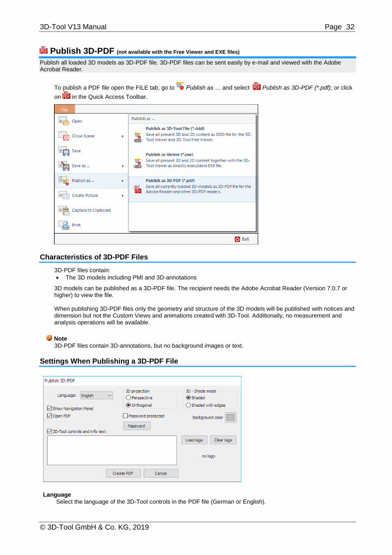
3D-Tool V13 Manual Page 32
© 3D-Tool GmbH & Co. KG, 2019
Publish 3D-PDF (not available with the Free Viewer and EXE files)
Publish all loaded 3D models as 3D-PDF file. 3D-PDF files can be sent easily by e-mail and viewed with the Adobe Acrobat Reader.
To publish a PDF file open the FILE tab, go to Publish as … and select Publish as 3D-PDF (*.pdf); or click
on in the Quick Access Toolbar.
Characteristics of 3D-PDF Files
3D-PDF files contain:
The 3D models including PMI and 3D-annotations
3D models can be published as a 3D-PDF file. The recipient needs the Adobe Acrobat Reader (Version 7.0.7 or higher) to view the file. When publishing 3D-PDF files only the geometry and structure of the 3D models will be published with notices and dimension but not the Custom Views and animations created with 3D-Tool. Additionally, no measurement and analysis operations will be available.
Note
3D-PDF files contain 3D-annotations, but no background images or text.
Settings When Publishing a 3D-PDF File
Language
Select the language of the 3D-Tool controls in the PDF file (German or English).

3D-Tool V13 Manual Page 33
© 3D-Tool GmbH & Co. KG, 2019
3D projection
Designate whether the model will be displayed orthogonal or in perspective, when the 3D-PDF file is opened.
3D - Shade mode
Designate whether the model will be displayed shaded or shaded with edges, when the 3D-PDF file is opened.
Show Navigation Panel
Activate the Navigation Panel in the PDF document, which shows the model tree (the part structure of a model), as well as some default views.
Open PDF
Open the PDF document right after it was created.
Password protected
Protect the 3D-PDF file with a password against unauthorized use.
Password
Enter a password to protect the 3D-PDF file.
Background color
Designate the background color of the 3D-PDF.
3D-Tool controls and info text
Activate additional 3D-Tool controls and info text in the PDF document that make it possible to:
Save and load views.
Change the color of parts and assemblies.
Explode assemblies.
Display an info text, if one has been added.
Display a company logo, if it has been loaded.
Load logo
Add a company logo that will be displayed in the 3D-PDF file.
Clear logo
Clear the loaded logo.
Note
Unzipping password protected 3D-Tool ZIP archives requires archive software supporting the AES 256 encryption standard. The default Windows ZIP feature does not support this encryption, so that third party software is required.

3D-Tool V13 Manual Page 34
© 3D-Tool GmbH & Co. KG, 2019
Save as ... STL, VRML, 3DS, PLY, OBJ, U3D (not available with the Free Viewer and EXE files)
Save a 3D model or 2D drawing under a new name and in one of the available file formats.
Save a model or drawing by clicking Save as ... in the File tab, and then select a model or drawing from the list.
File Formats Available For Export
3D-models
For 3D-models the following file formats are available for export:
3D-Tool DDD file *.ddd
Executable *.exe
3D-Studio file *.3ds
OBJ file *.obj
PDF file *.pdf
PLY file *.ply
STL binary file *.stl
U3D file *.u3d
VRML 2.0 file *.wrl
2D-drawings
For 2D-drawings the following file formats are available for export:
3D-Tool DDD file *.ddd
Executable *.exe
Note
The 3D-Tool Viewer principally exports faceted models (meshes) and no parametric CAD data (BREPs).
Save as … will only save the selected model or selected drawing. If you want to save multiple models
and/or drawings together within one 3D-Tool DDD or EXE file use Publish as… from the FILE tab, and
choose Publish as 3D-Tool File (*.ddd) or Publish as Viewer (*.exe).
Batch Mode
Convert files to executable 3D-Tool files (viewer and data) via command line or create your own batch files.
Automatically Publish 3D-Tool EXE Files
Required parameters
Start 3D-Tool, open a file, and publish it in the same directory as 3D-Tool EXE file by using the following command line: InstallationPath\3D-Tool.exe FilePath\CAD-file -s -exe

3D-Tool V13 Manual Page 35
© 3D-Tool GmbH & Co. KG, 2019
The -s parameter starts the automatic output. If a file path contains spaces, the complete file path and file name must be enclosed in quotation marks. Example: "C:\program files\3D-Tool V13\3D-Tool.exe" "D:\new data\model.stp" - s -exe
Optional parameters
Optional parameters can be combined in any order. -q:[high/low/cad/quick/noheal/custom] (Default: custom)
Specify the import settings to be used for opening CAD models. -q:custom = Use Chord Height and Angle Control as set in 3D-Tool Preferences -q:high = High quality -q:low = Low quality -q:cad = CAD graphical data -q:quick = Quick (visible BREPs only) -q:noheal = NoHeal (visible BREPs only without Healing) Example: "C:\program files\3D-Tool V13\3D-Tool.exe" "D:\new data\model.stp" -s -exe -q:cad -o: FilePath\FileName.exe
Specify the path and filename of the EXE file. If a file path contains spaces, the complete parameter must be enclosed in quotation marks. Folders that do not exist will be created. By specifying the file extension *.exe the parameter -exe can be omitted. Example: "C:\program files\3D-Tool V13\3D-Tool.exe" "D:\new data\model.stp" -s "-o:D:\new data\output\published_model.exe" -zip
Automatically zip the EXE file. Example: "C:\program files\3D-Tool V13\3D-Tool.exe" "D:\new data\model.stp" -s -exe -zip -zippw:Password
Automatically zip the EXE file and protect the zip-archive with a password. Example: "C:\program files\3D-Tool V13\3D-Tool.exe" "D:\new data\model.stp" -s -exe -zippw:XyZ321 -helpen
Publish the EXE file, including the offline help in English. Example: "C:\program files\3D-Tool V13\3D-Tool.exe" "D:\new data\model.stp" - s -exe -helpen
-helpde
Publish the EXE file, including the offline help in German. Example: "C:\program files\3D-Tool V13\3D-Tool.exe" "D:\new data\model.stp" - s -exe -helpde -m:ShortMessage
Publish the EXE file including a short message to be displayed when the file is opened. Example: "C:\program files\3D-Tool V13\3D-Tool.exe" "D:\new data\model.stp" - s -exe "-m:Request of 06. July 2015" -jpg or -bmp
Creates a JPG or BMP picture with four default views of the model in addition to the EXE file. Example: "C:\program files\3D-Tool V13\3D-Tool.exe" "D:\new data\model.stp" -s -exe -jpg
Note
Within Windows batch files (*.bat) special and international characters can only be used in file names and parameters if a corresponding code page is specified via CHCP command.
Unzipping password protected 3D-Tool ZIP archives requires archive software supporting the AES 256 encryption standard. The default Windows ZIP feature does not support this encryption, so that third party software is required.

3D-Tool V13 Manual Page 36
© 3D-Tool GmbH & Co. KG, 2019
Automatically Publish 3D-Tool DDD Files
Required parameters
Start 3D-Tool, open a file, and publish the file in the same directory as 3D-Tool DDD file by using the following command line: InstallationPath\3D-Tool.exe FilePath\CAD-file -s -ddd
If a file path contains spaces, the complete file path and file name must be enclosed in quotation marks. Example: "C:\program files\3D-Tool V13\3D-Tool.exe" "D:\new data\model.stp" - s -ddd
Optional parameters
Optional parameters can be combined in any order. -q:[high/low/cad/quick/noheal/custom] (Default: custom)
Specify the import settings to be used for opening CAD models. -q:custom = Use Chord Height and Angle Control as set in 3D-Tool Preferences. -q:high = High quality -q:low = Low quality -q:cad = CAD graphical data -q:quick = Quick (visible BREPs only) -q:noheal = NoHeal (visible BREPs only without Healing) Example: "C:\program files\3D-Tool V13\3D-Tool.exe" "D:\new data\model.stp" -s -ddd -q:cad -o: FilePath\FileName.ddd
Specify the path and filename of the DDD file. If a file path contain spaces, the complete parameter must be enclosed in quotation marks. Folders that do not exist will be created. By specifying the file extension *.ddd the parameter -exe can be omitted. Example: "C:\program files\3D-Tool V13\3D-Tool.exe" "D:\new data\model.stp" - s -ddd "-o:D:\new data\output\published_model.ddd" -zip
Automatically zip the DDD file. Example: "C:\program files\3D-Tool V13\3D-Tool.exe" "D:\new data\model.stp" - s -ddd -zip -zippw:Password
Automatically zip the DDD file and protect the zip-archive with a password. Example: "C:\program files\3D-Tool V13\3D-Tool.exe" "D:\new data\model.stp" - s -ddd -zippw:XyZ321
-m:ShortMessage
Publish the DDD file including a short message to be displayed when loading the DDD into 3D-Tool. Example: "C:\program files\3D-Tool V13\3D-Tool.exe" "D:\new data\model.stp" - s -ddd "-m:Request of 06. July 2015"
-jpg or -bmp
Creates a JPG or BMP picture with four default views of the model in addition to the DDD file. Example: "C:\program files\3D-Tool V13\3D-Tool.exe" "D:\new data\model.stp" -s -ddd -jpg
Note
Within Windows batch files (*.bat) special and international characters can only be used in file names and parameters if a corresponding code page is specified via CHCP command.
Unzipping password protected 3D-Tool ZIP archives requires archive software supporting the AES 256 encryption standard. The default Windows ZIP feature does not support this encryption, so that third party software is required.

3D-Tool V13 Manual Page 37
© 3D-Tool GmbH & Co. KG, 2019
Automatically Publish 3D-PDF Files
Required parameters
Start 3D-Tool, open a model, and publish the model in the same directory as 3D-PDF file by using the following command line: InstallationPath\3D-Tool.exe FilePath\CAD-file -s -pdf
If a file path contains spaces the complete file path and file name must be enclosed in quotation marks. Example: "C:\program files\3D-Tool V13\3D-Tool.exe" "D:\new data\model.stp" - s -pdf
Optional parameters
Optional parameters can be combined in any order. -q:[high/low/cad/quick/noheal/custom] (Default: custom)
Specify the import settings to be used for opening CAD models. -q:custom = Use Chord Height and Angle Control as set in 3D-Tool Preferences. -q:high = High quality -q:low = Low quality -q:cad = CAD graphical data -q:quick = Quick (visible BREPs only) -q:noheal = NoHeal (visible BREPs only without Healing) Example: "C:\program files\3D-Tool V13\3D-Tool.exe" "D:\new data\model.stp" -s -pdf -q:cad -o: FilePath\FileName.pdf
Specify the path and filename of the 3D-PDF file. If a file path contain spaces, the complete parameter must be enclosed in quotation marks. Folders that do not exist will be created. By specifying the file extension *.pdf the parameter -pdf can be omitted. Example: "C:\program files\3D-Tool V13\3D-Tool.exe" "D:\new data\model.stp" - s -pdf "-o:D:\new data\output\published_model.pdf" -en or -en
Activate the additional 3D-Tool controls in the 3D-PDF (cross section, explode, color) /en activates the controls in English language. /de activates the controls in German language. Example: "C:\program files\3D-Tool V13\3D-Tool.exe" "D:\new data\model.stp" - s -pdf -en
-jpg or -bmp
Creates a JPG or BMP picture with four default views of the model in addition to the PDF file. Example: "C:\program files\3D-Tool V13\3D-Tool.exe" "D:\new data\model.stp" -s -pdf -jpg
Note
Within Windows batch files (*.bat) special and international characters can only be used in file names and parameters if a corresponding code page is specified via CHCP command.
Automatically Save as STL, VRML, 3DS, PLY, OBJ or U3D File
Required parameters
Start 3D-Tool, open a model and publish the model in the same directory as STL, VRML, 3DS, PLY, OBJ or U3D file by using the following command line: InstallationPath\3D-Tool.exe FilePath\CAD-file -s -OutputFormat
If a file path contains spaces, the complete file path and file name must be enclosed in quotation marks. Supported output formats are: -stl
Saves the model as binary STL file. Example: "C:\program files\3D-Tool V13\3D-Tool.exe" "D:\new data\model.stp" - s -stl

3D-Tool V13 Manual Page 38
© 3D-Tool GmbH & Co. KG, 2019
-wrl
Saves the model as VRML file. Example: "C:\program files\3D-Tool V13\3D-Tool.exe" "D:\new data\model.stp" - s -wrl -3ds
Saves the model as binary 3DS file. Example: "C:\program files\3D-Tool V13\3D-Tool.exe" "D:\new data\model.stp" - s -3ds -ply
Saves the model as binary PLY file. Example: "C:\program files\3D-Tool V13\3D-Tool.exe" "D:\new data\model.stp" - s -ply -obj
Saves the model as OBJ file. Example: "C:\program files\3D-Tool V13\3D-Tool.exe" "D:\new data\model.stp" - s -obj -u3d
Saves the model as U3D file. Example: "C:\program files\3D-Tool V13\3D-Tool.exe" "D:\new data\model.stp" - s -u3d
Optional parameters
Optional parameters can be combined in any order. -q:[high/low/cad/quick/noheal/custom] (Default: custom)
Specify the import settings to be used for opening CAD models. -q:custom = Use Chord Height and Angle Control as set in 3D-Tool Preferences. -q:high = High quality -q:low = Low quality -q:cad = CAD graphical data -q:quick = Quick (visible BREPs only) -q:noheal = NoHeal (visible BREPs only without Healing) Example: "C:\program files\3D-Tool V13\3D-Tool.exe" "D:\new data\model.stp" -s -stl -q:cad -o: FilePath\FileName.OutputFormat
Specify the path and filename of the output file. If a file path contain spaces, the complete parameter must be enclosed in quotation marks. Folders that do not exist will be created. By specifying the file extension OutputFormat the parameter -OutputFormat can be omitted. Example: "C:\program files\3D-Tool V13\3D-Tool.exe" "D:\new data\model.stp" - s "-o:D:\new data\output\converted_model.stl"
-jpg or -bmp
Creates a JPG or BMP picture with four default views of the model in addition to the 3Dfile. Example: "C:\program files\3D-Tool V13\3D-Tool.exe" "D:\new data\model.stp" -s -stl -jpg
Note
Within Windows batch files (*.bat) special and international characters can only be used in file names and parameters if a corresponding code page is specified via CHCP command.
Automatically Create PNG, JPG or BMP Files
Required parameters
Start 3D-Tool, open a file, and create a JPG or BMP file in the same directory by using the following command line: InstallationPath\3D-Tool.exe FilePath\CAD-file -s -png resp. InstallationPath\3D-Tool.exe FilePath\CAD-file -s -jpg resp. InstallationPath\3D-Tool.exe FilePath\CAD-file -s -bmp If a file path contains spaces the complete file path and file name must be enclosed in quotation marks. Example: "C:\program files\3D-Tool V13\3D-Tool.exe" "D:\new data\model.stp" -s -jpg -o:FilePath\Filename.jpg

3D-Tool V13 Manual Page 39
© 3D-Tool GmbH & Co. KG, 2019
Optional parameters
Optional parameters can be combined in any order. -q:[high/low/cad/quick/noheal/custom] (Default: custom)
Specify the import settings to be used for opening CAD models. -q:custom = Use Chord Height and Angle Control as set in 3D-Tool Preferences. -q:high = High quality -q:low = Low quality -q:cad = CAD graphical data -q:quick = Quick (visible BREPs only) -q:noheal = NoHeal (visible BREPs only without Healing) Example: "C:\program files\3D-Tool V13\3D-Tool.exe" "D:\new data\model.stp" -s -jpg -q:cad
-o: FilePath\FileName.jpg
Specify the path and file name of the JPG/BMP file. If a file path contain spaces, the complete parameter must be enclosed in quotation marks. Folders that do not exist will be created. By specifying the file extension *.jpg or *.bmp the parameter -jpg and bmp can be omitted. Example: "C:\program files\3D-Tool V13\3D-Tool.exe" "D:\new\model.stp" -s "-o:D:\new data \output\model_picture.jpg"
Notes
The -jpg and -bmp parameters can be used as optional parameters combined with the export formats as described above.
Within Windows batch files (*.bat) special and international characters can only be used in file names and parameters if a corresponding code page is specified via CHCP command.
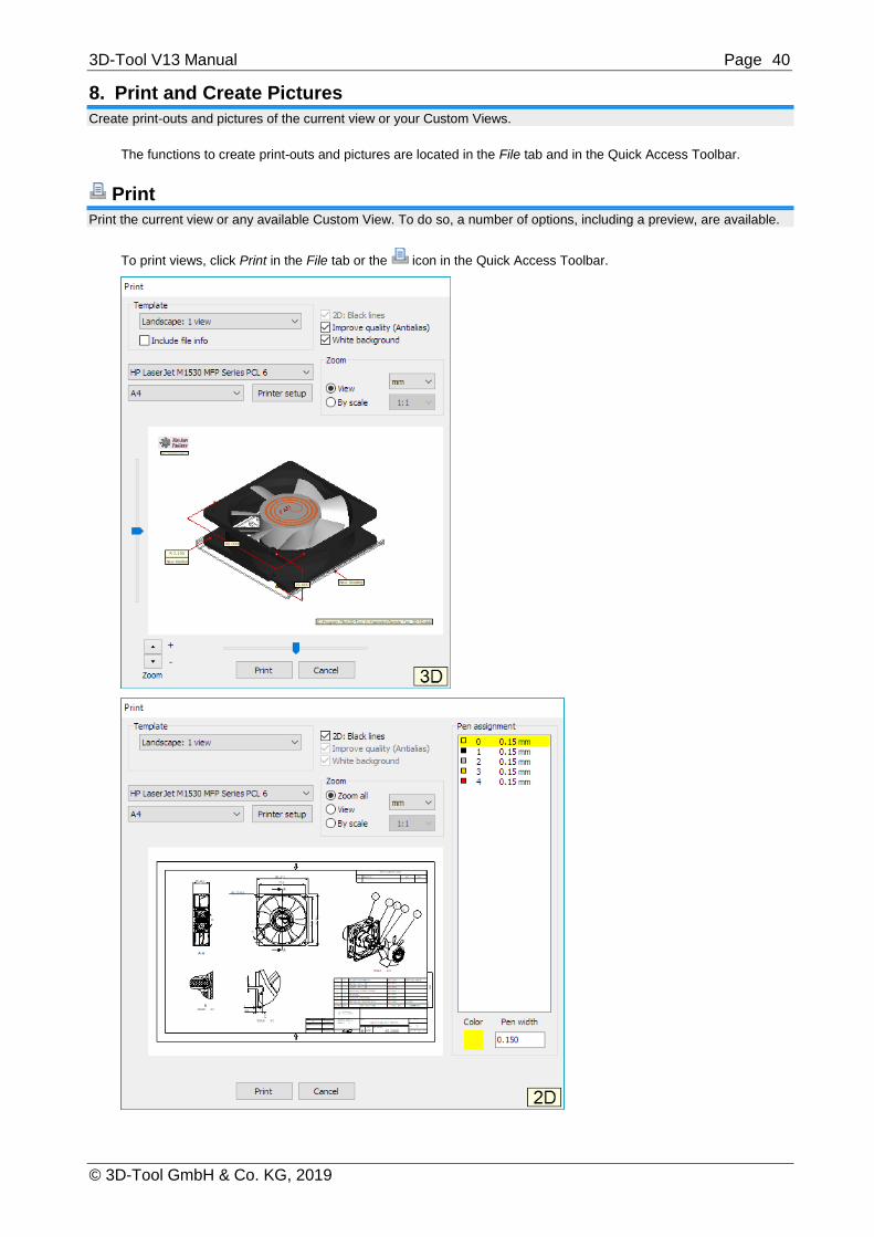
3D-Tool V13 Manual Page 40
© 3D-Tool GmbH & Co. KG, 2019
8. Print and Create Pictures Create print-outs and pictures of the current view or your Custom Views.
The functions to create print-outs and pictures are located in the File tab and in the Quick Access Toolbar.
Print the current view or any available Custom View. To do so, a number of options, including a preview, are available.
To print views, click Print in the File tab or the icon in the Quick Access Toolbar.

3D-Tool V13 Manual Page 41
© 3D-Tool GmbH & Co. KG, 2019
Template
Select a pre-defined template for printing. You can select the orientation of the paper (horizontal or vertical) and the number and type of views to be used.
Include file info (in 3D-models only)
Add the file path and name of a 3D-model in the lower right corner of the print-out. The file information option is available when only one model is loaded or when the Modell-Info tool is activated and only one model or its parts are selected in the Model Tree.
Printer and paper size
Select a printer and paper size from the two drop down lists.
Printer setup
Open the printer settings of the selected printer to make further adjustments.
Note
Selecting the horizontal or vertical paper orientation will not affect the format because the format of the Template selected in 3D-Tool will be used.
2D - Print black lines (for 2D-drawings only)
Print all lines and text of 2D-drawings in black.
Improve quality (Antialias) (in 3D-models only)
Use Antialias when printing to smooth the edges.
Transparent background
Do not print the (colored) background of 3D-models. When printing 2D-drawings, the background will not be printed unless the drawing is printed as Custom View within an accordant Template.
Zoom
Zoom all: (in 2D-drawings only) Fit a drawing to the selected paper size.
View: Print the current view.
Scale: Define a scale for the print-out.
Depending on the Template and Zoom, further controls are available near the preview picture to adjust the position
and zoom of the models and drawings.
Note
The Scale option is not available for views of models in Perspective View or for templates containing Custom Views.
Pen assignment (in 2D mode only)
Assign different line thicknesses to the colors of the drawing for the print-out.
Create Picture
Create a BMP or JPG image of the current view or any available Custom View. To do so, a number of options, including a preview, are available.
To create pictures, click Create Picture in the File tab or the icon in the Quick Access Toolbar

3D-Tool V13 Manual Page 42
© 3D-Tool GmbH & Co. KG, 2019
Template
Select a pre-defined template for the picture. You can select the orientation (horizontal or vertical) and the number and type of views to be used. Depending on the Template, further controls are available near the preview picture to adjust the position and zoom of the models and drawings.
Include file info (in 3D mode only)
Add the file path and name of a 3D-model in the lower right corner of the picture. The file information option is available only when one model is loaded or when the Modell-Info tool is activated and only one model or its parts are selected in the Model Tree.
2D - Print black lines (for 2D-drawings only)
Print all lines and text of 2D-drawings in black.
Improve quality (Antialias) (for 3D-models only)
Use Antialias when printing to smooth the edges. Antialias is only works with 3D-models.
Transparent background
Do not show the (colored) background of 3D-models and 2D-drawings.
File type
From the drop down list, select the file format:
PNG *.png
Creates a lossless PNG picture file
JPEG *.jpg Creates a compressed JPEG picture file. The quality of the JPEG compression can be set in the Preferences: Options tab > Preferences > Print/Picture/Snapshot
Bitmap *.bmp
Creates a lossless BMP picture file
Resolution
Select one of the pre-defined output sizes or activate Custom for a custom resolution. Unselect the Maintain aspect ratio option to set the picture width and height independently.
Notes
The maximum resolution depends on the graphics card and the operating system; therefore it could be less than 10000 pixels.
Pictures of 10000x10000 pixels will use a lot of working memory.

3D-Tool V13 Manual Page 43
© 3D-Tool GmbH & Co. KG, 2019
9. Common Functions This section informs you about common functions which are available in the 3D and the 2D mode. An important feature is the Custom Views because it is used by other functions.
3D Mode and 2D Mode
Use the 3D Mode to view 3D-models and the 2D Mode to view 2D-drawings.
To alternate between 3D and 2D click the 3D-Mode and 2D-Mode tab in the Mode group.
3D Turn on the 3D Mode to view 3D-models. Clicking the 3D-Mode tab will do the same.
2D Turn on the 2D Mode to view 2D-drawings. Clicking the 2D-Mode tab will do the same.
The File Tab
Use the File tab to load, save, publish files, and create print-outs or picture files. Additionally, a list of recently used files is shown.
Open
Open 3D-models and 2D-drawings. You can open multiple files by selecting them in the file open dialog.
Close Scene
Delete the 3D and/or 2D content that is currently loaded.
Save
Save a 3D model or 2D drawing. If the original file format is available, the file will be saved under its original name and format. Otherwise, you will be asked to choose a file name and format.
Save as ...
Save a 3D model or 2D drawing under a new name or file format. Choose the model or drawing you want to save from the list.
Publish as ...
Publish all currently loaded 3D models and/or 2D drawings. Choose the desired type of publishing:
Publish 3D-Tool File (*.ddd)

3D-Tool V13 Manual Page 44
© 3D-Tool GmbH & Co. KG, 2019
Save all 3D and 2D content to a DDD file for the 3D-Tool Viewer or the 3D-Tool Free Viewer.
Publish Viewer
Save all 3D and 2D content together with the 3D-Tool Viewer as a executable EXE file.
Publish 3D-PDF (*.pdf)
Publish all currently loaded 3D models as 3D-PDF file for the Adobe Reader or other 3D-PDF capable readers. Further information can be found in the chapter Publish and Save.
Create Picture
Create an image of the current view or any available Custom View. Choose the desired picture format:
Create PNG
Create an image in the PNG file format.
Create JPG
Create an image in the JPG file format.
Create BMP
Create an image in the BMP file format.
Capture to Clipboard
Select and copy a section of the screen to the Clipboard. Click the screen, hold the mouse button, and marquee select the desired section. To copy the complete screen just click the screen. Afterwards the picture can be pasted from the Clipboard into other applications. You can adjust settings for the capture function in the Preferences: Options tab > Preferences group > Preferences > Print/Picture/Capture
Print the current view or any available Custom View. Further information can be found in the chapter Print and Create Pictures.
Exit
Close 3D-Tool.
Notes
The functions to save and publish files are not available with the Free Viewer and 3D-Tool EXE files.
The functions to open and close files are not available with 3D-Tool EXE files.
To ease the editing of STL files, the "Save" function will automatically and without warning update open STL files with the state present in 3D-tool. To avoid the automatic update of existing STL files, the "Save as …" function must be used.

3D-Tool V13 Manual Page 45
© 3D-Tool GmbH & Co. KG, 2019
Custom Views
Save any 3D- and 2D-view as Custom View. Custom Views contain the state and orientation of 3D-models, the position and zoom of 2D-drawings, as well as all display settings.
Save and Select Custom Views
The functions to save and select Custom Views are located in the right info panel beneath the Model Tree.
[<] Previous Custom View
Load the previous Custom View from the Custom View List.
Master View
Show all parts, fit the parts to the display, and apply the default display settings.
[>] Next Custom View
Load the next Custom View from the Custom View List.
Save Custom View
Save the current view as Custom View. Enter a name in the succeeding window or overwrite an already existing view.
Undo View
Return to the previously displayed view.
Select a View from the list
Click the drop down list of Custom Views to open it. Move the cursor over the views in the list. A preview of the views will be displayed to the left of the list. Click the view you want to be displayed.
Notes
Custom Views will be added to the end of the list.
You may delete, arrange and rename Custom Views by using the Custom View Editor: 3D-Mode tab > Tools group > More tools
Why Use Custom Views?
3D-Tool offers many possibilities to show important aspects of a construction:
Rotate the models into the desired position and zoom in on important sections.
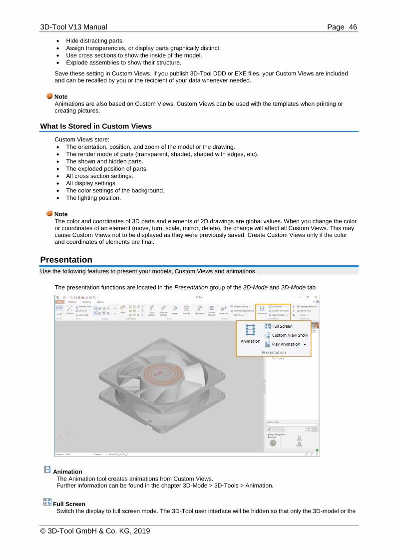
3D-Tool V13 Manual Page 46
© 3D-Tool GmbH & Co. KG, 2019
Hide distracting parts
Assign transparencies, or display parts graphically distinct.
Use cross sections to show the inside of the model.
Explode assemblies to show their structure.
Save these setting in Custom Views. If you publish 3D-Tool DDD or EXE files, your Custom Views are included and can be recalled by you or the recipient of your data whenever needed.
Note
Animations are also based on Custom Views. Custom Views can be used with the templates when printing or creating pictures.
What Is Stored in Custom Views
Custom Views store:
The orientation, position, and zoom of the model or the drawing.
The render mode of parts (transparent, shaded, shaded with edges, etc).
The shown and hidden parts.
The exploded position of parts.
All cross section settings.
All display settings
The color settings of the background.
The lighting position.
Note
The color and coordinates of 3D parts and elements of 2D drawings are global values. When you change the color or coordinates of an element (move, turn, scale, mirror, delete), the change will affect all Custom Views. This may cause Custom Views not to be displayed as they were previously saved. Create Custom Views only if the color and coordinates of elements are final.
Presentation
Use the following features to present your models, Custom Views and animations.
The presentation functions are located in the Presentation group of the 3D-Mode and 2D-Mode tab.
Animation
The Animation tool creates animations from Custom Views. Further information can be found in the chapter 3D-Mode > 3D-Tools > Animation.
Full Screen
Switch the display to full screen mode. The 3D-Tool user interface will be hidden so that only the 3D-model or the

3D-Tool V13 Manual Page 47
© 3D-Tool GmbH & Co. KG, 2019
2D-drawing is displayed. In full screen mode, right-click into the display to access often needed functions. To exit the full screen mode press [Esc] or via right-click into the display > Exit full screen.
Note
During the full screen mode, the Hardware acceleration is not available and the display will respond slower than usual.
Custom View Show
Start a slide show of all available Custom Views. All Custom Views will be displayed in order. Stop the Custom View Show by pressing Esc or by clicking into the display.
Start Animation Start an animation, e.g. Rotate right, and animations created with the Animation tool. Stop the animation by
pressing Esc or by clicking the display.
Change the Width of the Info Panel
Adjust the width of the right info panel to your personal needs.
Show and hide the info panel
To hide and show the info panel, click on the button on the left side of the list.
Normal and double size
To toggle the width between normal and double size, click underneath the 3D-Tool logo.
Adjust the size
The size of the info panel can be changed. Place the cursor on the left border of the panel and, after the cursor has changed into the <||> icon, hold down the left mouse button and drag the border.

3D-Tool V13 Manual Page 48
© 3D-Tool GmbH & Co. KG, 2019
10. 3D Mode This section informs you about the 3D mode of 3D-Tool. The 3D mode offers a large number of functions and tools to analyze models, assemblies and parts.
To display 3D-models, click the 3D Mode tab or the 3D Mode button in the Mode group.
Zoom Models
Besides the scroll wheel or the middle mouse button, you can use the following functions to zoom in on and out of the models in the display.
The functions to zoom and fit the models are located in the Zoom group of the 3D-Mode tab.
Zoom all
Fit everything visible in the display. This function is also assigned to the function key [F4].
Zoom In
Zoom into an area. Click into the display, hold down the mouse button, and move the marquee across the area to be zoomed. This function is also assigned to the function key [F2].
Zoom Out
Zoom out of the view. You may also zoom in and out using the scroll wheel. This function is also assigned to the function key [F3].
Previous View
Undo the last zoom, move, or rotation of the view. This function is also assigned to the function key [F5].

3D-Tool V13 Manual Page 49
© 3D-Tool GmbH & Co. KG, 2019
Rotate and Align Models
Use the following functions to rotate, fit and align the models in the display.
The functions to rotate and align the view are located in the Orientation group of the 3D-Mode tab.
Align View
Align the view to the X, Y and Z-axis of the coordinate system.
Align plane parallel to view
Select Align plane parallel to view and move the mouse pointer over the model. Planes to align them will be
highlighted in blue. Click to align the selected plane parallel to view.
Align curve/edge perpendicular to view
Select Align curve/edge perpendicular to view and move the mouse pointer over the model. Curves/edges to
align will be highlighted in blue. Click to align the selected curve/edge perpendicular to view.
Align curve/edge horizontal in view
Select Align curve/edge horizontal in view and move the mouse pointer over the model. Curves/edges to align
will be highlighted in blue. Click to align the selected curve/edge hoizontal in the view.
Align curve/edge vertical in view
Select Align curve/edge vertical in view and move the mouse pointer over the model. Curves/edges to align will
be highlighted in blue. Click to align the selected curve/edge vertical in theview.
Align cross section parallel to view
With activated Cross Section tool, click to align the selected cross section plane parallel to the view.
Front View
Rotate the view to front view, and fit all visible parts in the display.
Back View
Rotate the view to back view, and fit all visible parts in the display.
Left View
Rotate the view to left view, and fit all visible parts in the display.

3D-Tool V13 Manual Page 50
© 3D-Tool GmbH & Co. KG, 2019
Right View
Rotate the view to right view, and fit all visible parts in the display.
Top View
Rotate the view to top view, and fit all visible parts in the display.
Bottom View
Rotate the view to bottom view, and fit all visible parts in the display.
3D View
Rotate the view to the standard 3D view, and fit all visible parts in the display.
Rotate Horizontal 180°
Rotate the view horizontally by 180 degrees.
Rotate Vertical 180°
Rotate the view vertically by 180 degrees.
Rotate Normal 90°
Rotate the view by 90 degrees around the screen center.
Save Orientation
Save the current zoom and orientation of the view. To restore the view, use Load Orientation.
Load Orientation
Restore a previously saved zoom and orientation of the view. To save views, use Save Orientation.
Change the Display of Models
Use different render modes, such as shaded display and the display as wire frame. Also, you may adjust the display, e.g. show the not connected edges of a model.
Change the Render Mode of Models
The functions to change the render mode of models are located in the Display group of the 3D-Mode tab.
Shaded Display
Display all parts shaded.

3D-Tool V13 Manual Page 51
© 3D-Tool GmbH & Co. KG, 2019
Shaded with Edges
Display all parts shaded with black edges.
Shaded with Triangles
Display all parts shaded with triangles.
Wire Frame Display
Display all parts as wire frame.
Hidden Line Colored Display
Display all parts as hidden line graphics with lines in the color of the parts.
Hidden Line Black/White Display
Display all parts as hidden line graphics with black lines on a white background.
Triangles
Display all parts as outlines of their triangles.
Points
Display all parts as points.
Tip
Right-click on parts to display them in an individual shade mode.
Notes
To change the number of edges displayed with the render modes Shaded with Edges, Wire Frame, and Hidden Line, use Change Wire Frame Angle in the Options tab.
When opening CAD files (STEP, IGES, CATIA, Pro/E, etc.), the face boundaries of models can be loaded and displayed as curves. To do so, activate the Load face boundaries as curves option in the Import Settings.
Adjust the Display
The functions to adjust the display are located in the Display group of the 3D-Mode tab.
Show Curves
Show the 3D curves of the models.

3D-Tool V13 Manual Page 52
© 3D-Tool GmbH & Co. KG, 2019
Note
When opening CAD files (STEP, IGES, CATIA, Pro/E, etc.), the face boundaries of models can be loaded and displayed as curves. To do so, activate the Load face boundaries as curves option in the Import Settings.
Show PMI
Show the Product Manufacturing Information present in the models.
Show Dimensions and Markups Show the 3D dimensions and markups created with the Measure and Markup tool.
Show Exploded
Show the models exploded. Use the Explode tool to create explosion data for your models.
Perspective
Use perspective view instead of orthogonal view.
Display Back Faces Like Front Faces
Display shaded faces with same colored back faces.
Display Red Back Faces
Display shaded faces with red back faces.
Display No Back Faces
Display shaded faces without back faces. This speeds up the display.
Note
Especially with STL files, it is possible that front faces are inverted. In this case, the faces cannot be seen with the default setting Display No Back Faces. Change the display of the back faces to Display Back Faces Like Front Faces to solve the problem.
Show Open Edges
Show the edges of planes that are not connected in yellow.
Show Coordinate System
Show the absolute coordinate system as x-, y- and z-axis starting at (0,0,0).
3D-Compass
Show the x-, y- and z-axis as orientation in the lower left corner of the display.
Shiny Colors
Display surfaces with bright light reflections that give the model a shiny look and increase the 3D-effect. Switch off the shiny colors, e.g. for a more technical viewing. The intensity of the reflection can be set in the Preferences: Options tab > Preferences button > 3D-color
Smooth Display
Display shaded faces smoothed based on their smooth vectors. If smoothing is not satisfactory, use Adjust Smoothing in the Options tab to calculate new smooth vectors.

3D-Tool V13 Manual Page 53
© 3D-Tool GmbH & Co. KG, 2019
Change Lighting, White Background
Change the lighting position to improve the contrast and show details more vividly. Use a white background for screenshots.
The functions to change the Lighting Position and to switch to a White background are located in the right info panel below the Model Tree.
Change the Lighting Position
Adjust the lighting position by dragging the yellow light point to any position or choose Default.
Switch to White Background
Left of the lighting, you can switch between Normal and White background. This is useful:
To take screenshots of the current view.
If a model is displayed as wire frame or hidden line and the lines are difficult to see with the normal background.
Note The color and the gradient of the normal background can be adjusted in the 3D-Display Options group of the Options tab.
The Model Tree
This section informs you about using the Model Tree in the right Info Panel.
Note:
The Model Tree is not available with the 3D tools Tooling Analysis, Placement, Wall Thickness Analysis, Repair, and RP-Layout.

3D-Tool V13 Manual Page 54
© 3D-Tool GmbH & Co. KG, 2019
Use the Model Tree
Use the Model Tree to show and hide models, assemblies, and parts and to select them for further steps.
Elements of the Model Tree
The Model Tree can contain the following elements:
Active model / Inactive model
Assembly shown / Assembly hidden
Part shown / Part hidden
Click the icons of assemblies and parts to hide and show them.
Click the or the icon in front of assemblies to expand or collapse them.
Double-click the names of models, assemblies, and parts to fit them in the display. Additionally, models will be activated for the Placement, Wall Thickness Analysis and Repair tool.
Move the cursor over the models, assemblies, and parts in the Model Tree to highlight them for a short time in the display. This can be deactivated in the preferences of 3D-Tool: Options tab > Preferences group > Preferences > Model Tree
Selection on the Model Tree
Single selection
Click the names of models, assemblies, and parts to select them.
Range selection
To select a range of parts in the Model Tree, click a part and then press [Shift] while clicking another part. This will select the clicked parts and all the parts in between.
Multiple selection
To select multiple parts in the Model Tree, click a part then press [Ctrl] while clicking additional parts.
Selection on the Model
Single selection
To select a part on the model, double-click the desired part or press the Shift key while clicking the part.
Multiple selection
To select multiple parts on the model, double-click a part on the model and then press [Shift] and [Ctrl] while clicking additional parts.
Marquee select
To marquee, select parts by a selection rectangle click on Pick Part from the Model Tree group. In the display,
press and hold the left mouse button and drag the selection rectangle over all wanted parts. Release the mouse button and all parts that are completely within the rectangle will be selected.

3D-Tool V13 Manual Page 55
© 3D-Tool GmbH & Co. KG, 2019
Part Display
Hide and show the models, assemblies and parts selected on the Model Tree or change their graphical display.
The functions to show and hide parts and to change their graphical display are located in the right info panel above the Model Tree.
Show Parts
Show the parts and assemblies selected in the Model Tree.
Hide Parts
Hide the parts and assemblies selected in the Model Tree.
Show Selection Only
Show the parts and assemblies selected in the Model Tree and hide all others.
Show All
Show all models, assemblies and parts.
Hide All
Hide all models, assemblies and parts.
Search in Model Tree
Search for parts or assemblies in the Model Tree.
Change Color of Parts
Change the color of the parts and assemblies selected in the Model Tree.
Shaded Parts
Display the parts and assemblies selected in the Model Tree as shaded.
Shaded Parts with Edges
Display the parts and assemblies selected in the Model Tree as shaded with black edges.
Wire Frame Parts
Display the parts and assemblies selected in the Model Tree as wire frame.

3D-Tool V13 Manual Page 56
© 3D-Tool GmbH & Co. KG, 2019
Reset Part Display
Reset the parts and assemblies selected in the Model Tree to the global shade mode as set in the Display group.
Parts Transparency On
Display the parts and assemblies selected in the Model Tree transparent. Adjust the transparency in the 3D-Tool preferences: Options tab > Preferences group > Preferences > 3D-Color
Parts Transparency Off
Display the parts and assemblies selected in the Model Tree solid.
Arrange and Delete Parts
Delete, combine, move, and sort the parts in the Model Tree.
The functions to arrange and delete parts are located in the Model Tree Group of the 3D-Mode tab.
Expand All
Expand all models and assemblies in the Model Tree. To expand a single model or assembly, click on the plus symbols in the Model Tree.
Collapse All
Collapse all models and assemblies in the Model Tree. To collapse a single model or assembly, click on the minus symbols in the Model Tree.
Pick Part
To select one single part, just click on the part on the model. To select multiple parts, press and hold the mouse button, then marquee select the parts by selection rectangle.
Highlight Selection
Highlight the parts and assemblies selected in the Model Tree in red.
Delete Parts
Delete all parts and assemblies selected in the Model Tree.
Combine Parts
Combine all parts selected in the Model Tree to one part. The original names of the parts and their sectioning will be lost. If a model or assembly is selected, all of its parts will be combined.

3D-Tool V13 Manual Page 57
© 3D-Tool GmbH & Co. KG, 2019
Rearrange Parts
Move the parts selected in the Model Tree to an existing or new assembly or model that can be specified in the following dialog:
Move to existing assembly or model Select the assembly or model in the list, and click OK.
Move to new assembly Select the position of the new assembly in the list, and click on New assembly. The new assembly will be created. The name of the assembly can be changed through a slow double-click on the name or with the Rename button. Click OK to move the selection to the new assembly.
Move to new model Click on New model and the new model will be created. The name of the new model can be changed through a slow double-click on the name or with the Rename button. Click OK to move the selection to the new model.
Move Up
Moves the selected model, assembly, or part one position up in the Model Tree.
Move Down
Move the selected model, assembly, or part one position down in the Model Tree.
Sort Model Tree
Sort the parts in the Model Tree. Only the parts of the active model will be sorted by default. Select For all parts and models to extend the sorting to all models in the Model Tree. You can sort by:
Number of facets
Volume
Volume of boundary box
Number of open edges,
Part name.
Selecting Direction will let you decide if the parts will be sorted upward or downward. Rename parts creates new continuing element names after sorting. Caution: Old names will be lost.
3D - Tools
This section informs you about using the 3D-Tools.
Cross Section
Use the Cross Section tool to view the inner structure of a model as well as selecting and measuring parts that are difficult to access.
To create cross sections in 3D-Mode, click Cross Section in the Tools group.
After activating the tool, the model will be displayed sectioned. The section settings are shown in the top of the display. The cross section controls are shown in the display in front of the model.

3D-Tool V13 Manual Page 58
© 3D-Tool GmbH & Co. KG, 2019
Position and Align the Cross Section
Choose cross section plane
To choose one of the three standard planes as cross section plane, do one of the following:
In the section settings choose one of the 3 standard planes:
XY-Plane
XZ-Plane
YZ-Plane
Click one of the transparent planes of the cross section controls.
Pick cross section position on the model
To position and align the cross section by mouse click on the model the cross section settings offer the following:
Set cross section position
Select Set cross section position and move the mouse pointer over the model. Points to set the cross
section plane will be highlighted in blue. Click to move the cross section plane to the point.
Set cross section position perpendicular to curve/edge
Select Set cross section position perpendicular to curve/edge and move the mouse pointer over the model.
Curves/edges to set the cross section plane will be highlighted in blue. Click to move the cross section plane to the middle of the curve/edge and align it perpendicular to the curve/edge.
Set cross section position parallel to plane
Select Set cross section position parallel to plane and move the mouse pointer over the model.
Model planes to set the cross section plane will be highlighted in blue. Click to align the cross section plane parallel to the model plane.
Set cross section position to center of a circle
Select Set cross section position to center of a circle and move the mouse pointer over the model. Centers
of circles to set the cross section plane will be highlighted in blue. Click to move the cross section plane to the center of the circle.
Move the section plane
To move the section plane, do one of the following:
Move the slider in the section settings.
Enter a value in box above the slider.
Click the small buttons left and right of the slider. The << and >> buttons move the section plane in big steps. The < and > buttons move the section plane in small steps.
In the cross section controls click the shaft of the red arrow, hold down the mouse button and drag the section plane to the wanted position.
Rotate the section plane
To rotate the section plane around the x, y, or z-axis, do one of the following:
Drag the sliders in the section settings.
Enter values into the boxes behind the sliders.
Switch the displayed side of the model
To display a different side of the sectioned model, do one of the following:
In the section settings, choose one of the options Side 1, Side 2, or Cross section. Cross section will show only the cross section and hide both sides of the model.
In the cross section controls, click the head of the red arrow to switch between Side 1 and Side 2.
Tips
Use cross sections with the Measure/Markup tool to measure inaccessible parts. Also, the points and edges of the section line can be measured.
Cross sections can be saved as a Custom Views. All cross section settings will be saved, including parts excluded from the cross section.

3D-Tool V13 Manual Page 59
© 3D-Tool GmbH & Co. KG, 2019
Using the Cross Section Controls
To activate the cross section controls, select Show cross section controls from the Cross section options.
Move the section plane
To move the section plane, click the shaft of the red arrow, hold down the mouse button and drag the section plane to the wanted position.
Switch the displayed side of the model
To display a different side of the sectioned model, click the head of the red arrow to switch between Side 1 and Side 2.
Choose cross section plane
To choose one of the three standard planes as cross section plane, click one of the transparent planes of the cross section controls
Display Parts Uncut
To display a part uncut, right-click the part on the model or in the model tree and choose Cross section on/off .
To display a part cut again, use Cross section on/off once more.
To display all parts cut again, select Show all parts sectioned from the Cross section options.
Cross Section Options
Show all parts sectioned
Use the cross section on all parts. Uncut parts will be sectioned again.
Export cross section as DXF
Save the current section line as a 2D DXF file. The Transform to xy-plane option transforms the section line to the standard XY-plane, so the cross section will
be shown accurately in 2D-CAD programs. Deselect this option to keep the 3D orientation of the section plane for a 3D-CAD program.
Show cross section controls
Show the 3D cross section controls. The cross section controls let you move the section plane, switch the displayed side of the model, and change the section plane.
Fill section
Fill the cross section using the colors of the cut parts.
Section line
Show/hide the section line. Change the color of the line in the 3D-Tool preferences: Options tab > Preferences group > Preferences > 3D section
Measure and Markup
Use the Measure/Markup tool to add 3D dimensions and markups to the models, and images and text to the background.
The Measure/Markup tool is located in the Tools group of the 3D-Mode tab.
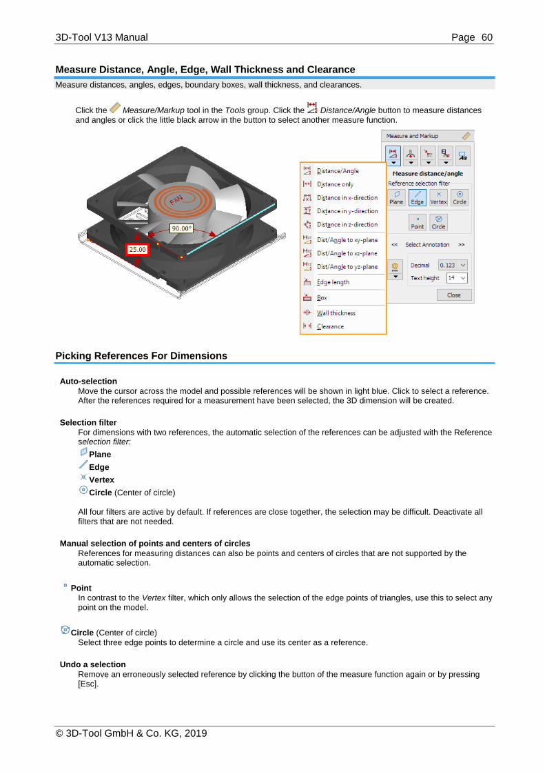
3D-Tool V13 Manual Page 60
© 3D-Tool GmbH & Co. KG, 2019
Measure Distance, Angle, Edge, Wall Thickness and Clearance
Measure distances, angles, edges, boundary boxes, wall thickness, and clearances.
Click the Measure/Markup tool in the Tools group. Click the Distance/Angle button to measure distances
and angles or click the little black arrow in the button to select another measure function.
Picking References For Dimensions
Auto-selection
Move the cursor across the model and possible references will be shown in light blue. Click to select a reference. After the references required for a measurement have been selected, the 3D dimension will be created.
Selection filter
For dimensions with two references, the automatic selection of the references can be adjusted with the Reference selection filter:
Plane
Edge
Vertex
Circle (Center of circle)
All four filters are active by default. If references are close together, the selection may be difficult. Deactivate all filters that are not needed.
Manual selection of points and centers of circles
References for measuring distances can also be points and centers of circles that are not supported by the automatic selection.
Point
In contrast to the Vertex filter, which only allows the selection of the edge points of triangles, use this to select any point on the model.
Circle (Center of circle)
Select three edge points to determine a circle and use its center as a reference.
Undo a selection
Remove an erroneously selected reference by clicking the button of the measure function again or by pressing [Esc].

3D-Tool V13 Manual Page 61
© 3D-Tool GmbH & Co. KG, 2019
Distance/Angle
Measure the distance or the angle between two references based on the type and location of the references.
Combination Measure
Plane Plane Measures distance when the planes are parallel. Measures angle when the planes are not parallel.
Plane Edge Measures distance when they are parallel. Measures angle when they are not parallel.
Plane Vertex Distance of the vertex perpendicular to the plane.
Plane Circle Distance of the center of the circle perpendicular to the plane.
Edge Edge
Measures distance when the edges are parallel. Measures angle when the edges are not parallel but on one plane. No measure when the edges are not parallel and not on one plane.
Edge Vertex Distance of the vertex perpendicular to the edge.
Edge Circle Distance of the center of the circle perpendicular to the edge.
Vertex Vertex Distance of the vertices
Vertex Circle Distance of the vertex to the center of the circle.
Circle Circle Distance of one center to the other center of a circle.
Distance
Measure the distance between two references. Only references that can be used for distance measurement can be selected.
Distance in X-, Y- and Z-Direction
Measure the distance between two references along the axes of the coordinate system. Only references that can be used for distance measurement can be selected.
Distance/Angel to XY, XZ- and YZ-Plane
Measure the distance or the angle between a reference and one of the standard planes based on the type and location of the reference.
Combination Measure
Standard plane Plane Measures distance when they are parallel. Measures angle when they are not parallel.
Standard plane Edge Measures distance when they are parallel. Measures angle when they are not parallel.
Standard plane Vertex Distance of the vertex perpendicular to the plane.
Standard plane Circle Distance of the center of the circle perpendicular to the plane.
Edge Length
Measure the length of an edge.

3D-Tool V13 Manual Page 62
© 3D-Tool GmbH & Co. KG, 2019
Boundary Box
Measure the length, width, and height of a model. Activate Boundary box of a part to measure the length, width,
and height of parts. The model or part under the cursor will be shown in light blue.
Wall Thickness
Measure the wall thickness at any point on the model. The wall thickness is calculated perpendicularly to the surface at the measuring point and independent of the viewing angle. Measuring points under the cursor will be shown in light blue.
Clearance
Measure the clearance between any point on the model and the surface that is across from it. The clearance is calculated perpendicularly to the surface at the measuring point and independent of the viewing angle. Measuring points under the cursor will be shown in light blue.
Measure Radius And Diameter
Measure radii and diameters.
Click the Measure/Markup tool in the Tools group. Click the Radius button to measure radii or click the little
black arrow in the button to select another measure function.
Measure Radius
Measure the radius of a circle. Move the cursor across the model, and the automatic selection highlights possible circles in light blue. Click to select a circle. If the automatic selection does not find the wanted circle, activate the option By 3 points and select three edge points on the circle to be measured. To make the selection easier, the edge points are shown.
Measure Diameter
Measure the diameter of a circle. Move the cursor across the model, and the automatic selection highlights possible circles in light blue. Click to select a circle. If the automatic selection does not find the wanted circle, activate the option By 3 points and select three edge points on the circle to be measured. To make selection easier the edge points are shown.
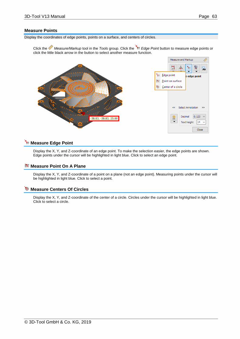
3D-Tool V13 Manual Page 63
© 3D-Tool GmbH & Co. KG, 2019
Measure Points
Display the coordinates of edge points, points on a surface, and centers of circles.
Click the Measure/Markup tool in the Tools group. Click the Edge Point button to measure edge points or
click the little black arrow in the button to select another measure function.
Measure Edge Point
Display the X, Y, and Z-coordinate of an edge point. To make the selection easier, the edge points are shown. Edge points under the cursor will be highlighted in light blue. Click to select an edge point.
Measure Point On A Plane
Display the X, Y, and Z-coordinate of a point on a plane (not an edge point). Measuring points under the cursor will be highlighted in light blue. Click to select a point.
Measure Centers Of Circles
Display the X, Y, and Z-coordinate of the center of a circle. Circles under the cursor will be highlighted in light blue. Click to select a circle.
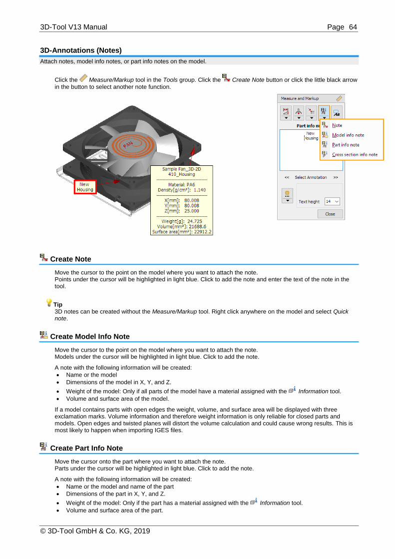
3D-Tool V13 Manual Page 64
© 3D-Tool GmbH & Co. KG, 2019
3D-Annotations (Notes)
Attach notes, model info notes, or part info notes on the model.
Click the Measure/Markup tool in the Tools group. Click the Create Note button or click the little black arrow
in the button to select another note function.
Create Note
Move the cursor to the point on the model where you want to attach the note. Points under the cursor will be highlighted in light blue. Click to add the note and enter the text of the note in the tool.
Tip 3D notes can be created without the Measure/Markup tool. Right click anywhere on the model and select Quick note.
Create Model Info Note
Move the cursor to the point on the model where you want to attach the note. Models under the cursor will be highlighted in light blue. Click to add the note.
A note with the following information will be created:
Name or the model
Dimensions of the model in X, Y, and Z.
Weight of the model: Only if all parts of the model have a material assigned with the Information tool.
Volume and surface area of the model.
If a model contains parts with open edges the weight, volume, and surface area will be displayed with three exclamation marks. Volume information and therefore weight information is only reliable for closed parts and models. Open edges and twisted planes will distort the volume calculation and could cause wrong results. This is most likely to happen when importing IGES files.
Create Part Info Note
Move the cursor onto the part where you want to attach the note. Parts under the cursor will be highlighted in light blue. Click to add the note.
A note with the following information will be created:
Name or the model and name of the part
Dimensions of the part in X, Y, and Z.
Weight of the model: Only if the part has a material assigned with the Information tool.
Volume and surface area of the part.

3D-Tool V13 Manual Page 65
© 3D-Tool GmbH & Co. KG, 2019
If a part has open edges the weight, volume, and surface area will be displayed with three exclamation marks. Volume information and therefore weight information is only reliable for closed parts and models. Open edges and twisted planes will distort the volume calculation and could cause wrong results. This is most likely to happen when importing IGES files.
Create Cross Section Info Note
Activate the Cross section tool. Move the cursor on the section of the part where you want to attach the note. The section under the cursor will be highlighted in light blue. Click to add the note.
A permanent red section line is created on the part. A note with the following information will be created on the section line:
Name or the model and name of the part
Number of segments
Length of the section line
Surface area of the sectioned part
Background Images And Text
Add background pictures in the PNG, JPG and BMP format, and add background texts.
Click the Measure/Markup tool in the Tools group.
Then click the Add Background Images or Text button.
Add Background Images Or Text
Add picture
Add a picture in the PNG, BMP or JPEG format as background. Position the picture in the display by dragging it while pressing the left mouse button.
Add text
Add a background text. Enter the text, and it will be displayed in a text box in the background. Position the text in the display by dragging it while pressing the left mouse button.
Note
The position of background pictures and texts, measured in pixels, is in reference to the upper left corner of the display. The position of background pictures and text changes with different display resolutions, hence positioning them on the top left is favorable.

3D-Tool V13 Manual Page 66
© 3D-Tool GmbH & Co. KG, 2019
Adjust And Delete Dimensions/Markups
Change the position, color, and size of dimensions and markups. Delete dimensions and markups that are no longer required
To adjust dimensions and markups, activate the Measure/Markup tool in the Tools group.
Move Dimensions/Markups
Movable elements of a dimension/markup will be highlighted in light blue under the cursor. Move the following elements by dragging them while pressing the left mouse button:
Text box of any dimension/markup
The points of reference of distance dimensions if on an edge or a plane
The points of reference of notes
Change Of Dimensions/Markups
Select a dimension/markup. To do so, click on the text box or use the << and >> button near Select Annotation.
Change the decimals of dimensions by choosing a value from the drop down list.
Change the text height of dimensions/markups by choosing a value from the drop down list.
Use the Change dimensions/markup button to change further attributes of a dimension/markup:
Foreground color is the color of the text.
Background color is the color of the text box.
Line color is the color of the carrying lines.
Edit info text allows adding additional text to dimensions/markups.
Stay on top displays a dimension/markup always in front of the model. This prevents the dimension/markup
to be hidden by the model.
Free move (distance dimensions between planes only)
Allows to move the text box and carrying lines of a distance dimensions to any position in the 3D space, as long as the measuring references are planes.
Show extended info (for distance dimensions, radius, and diameter)
Shows additionally the distances along the X, Y, and Z-axis for distance dimensions. Shows additionally the X, Y, and Z-coordinate of the center of the circle for radii and diameters.

3D-Tool V13 Manual Page 67
© 3D-Tool GmbH & Co. KG, 2019
Tip
Change the attributes of dimensions/markups through the context menu by just right-clicking the text box of a dimension/markup.
Notes
Color changes will not be visible until the dimension/markup has been deselected.
The default settings of all new dimensions/markups can be designated through: Options tab > Preferences group > Preferences > 3D-Annotations.
Delete Dimensions/Markups
To select a dimension/markup to be deleted, do one of the following:.
Click on the text box of the wanted Dimension/Markup.
Use the << and >> buttons near Select Annotation.
To delete the selected dimension/markup, do one of the following:
Press [Del] on the keyboard.
Or click on the Change dimension/markup button and select Delete.
Delete all deletes all dimensions/markups and all background pictures and texts.
Adjust And Delete Background Images And Texts
Background pictures and texts can be moved. The text box color and text size of background texts can be changed.
To adjust background images and text, activate the Measure/Markup tool in the Tools group.
Move Background Images And Texts
Click the Add background image or text button.
Move background images and texts by dragging them while pressing the left mouse button.
Note
The position of background pictures and texts, measured in pixels, is in reference to the upper left corner of the display. The position of background pictures and text changes with different display resolutions, hence positioning them on the top left is favorable.

3D-Tool V13 Manual Page 68
© 3D-Tool GmbH & Co. KG, 2019
Change Attributes Of Background Texts
Click the Add background image or text button.
Click a background text to select it and then do one of the following:
Change text, text color and text height by clicking Change text.
Change only the Text height by choosing a value from the drop down list.
Change the color of the text and the text box by clicking and selecting Foreground color (Text) or Background color (Box).
Add additional text for background texts by clicking and selecting Edit info text.
Notes
Color changes will not be visible until the background text has been deselected.
The default settings of all new dimensions/markups can be designated through: Options tab > Preferences group > Preferences > 3D-Annotations.
Delete Background Images And Texts
Click the Add background image or text button.
Click a background image or text to select it. To delete the selection, do one of the following:
Press [Del] on the keyboard.
Or click on the Change dimension/markup button and select Delete.
Delete all deletes all dimensions/markups and all background pictures and texts.The Delete all button deletes all background images, texts, and dimensions/markups.
Painter
Use the Painter tool to change the color of models, parts, surfaces, curves and PMI.
The Painter tool is located in the Tools group of the 3D-Mode tab.
Automatic Color
Models
Automatically assign different colors to all models.
Parts
Automatically assign different colors to all parts. Select the One model option to color the parts of a specific model. Select the All models option to color the parts of all models.

3D-Tool V13 Manual Page 69
© 3D-Tool GmbH & Co. KG, 2019
Surfaces
Automatically assign different colors to all faces. Select the One model option to color the faces of a specific model. Select the All models option to color the faces of all models.
Manual Color
Color
To set the paint color:
Click the Current paint color button and pick a color from the color palette.
Or click Pick a color from model and then click on a color on the model.
Single object select
The following selection modes are available:
Change color of surfaces, curves, and PMI
Change color of a single triangle
Change color of a plane surface
Change color of connected triangles
Change color of connected triangles in the same color. Move the mouse pointer over the model. Details to the selection mode details of the model will be highlighted in bright blue according to the selection mode. Click to change the color of the highlighted elements.
Marquee select
The following marquee selection modes are available:
Marquee select curves.
Marquee select triangles.
Marquee select PMI. Click into the display, hold the mouse button and drag the selection rectangle over the wanted elements. All elements that are completely within the selection rectangle will be selected and highlighted in bright blue. To
change the color of the selected elements click Change color of selected elements. To remove the selection
without changing the color click Reset selection.
Note
The marquee selection modes will not only select the visible elements but also all hidden elements behind them.
Explode
Use the Explode tool to manually or automatically create an exploded view of your models.
The Explode tool is located in the Tools group of the 3D-Mode tab.

3D-Tool V13 Manual Page 70
© 3D-Tool GmbH & Co. KG, 2019
Manual Explode
Selection mode
Mouse
Select a part by clicking on the model. Move the cursor onto a part of the model in the display and move the part while pressing the left mouse button. In this mode only single parts can be moved.
Element List
Pick models, assemblies, and parts in the Model Tree. All parts selected in the Model Tree will be displayed in red. Move the cursor onto one of the selected parts of the model in the display and move the parts while pressing the left mouse button.
Move parts
Move the selection by dragging it while pressing the left mouse button. For an easier positioning, deselect one or two of the axes x, y, z under Move direction or enter values in the x, y, and z fields, and then click the Move button.
Rotate parts
Rotate the selection by dragging it while pressing the left mouse button. Choose the axis of rotation in Rotation axis.
Axis: Rotation around one of the center axes (ax, ay, az) of the selection.
Screen: Rotation around one of the screen axes (sx, sy, sz). These axes depend on the viewing angle. The
sz-axis points to the viewer, the sx-axis points right, and the sy-axis points up.
The angle of rotation is displayed in the Angle field. For an exact rotation, enter a value and click the Rotate button.
Copy position from another part
Copy the movement and rotation of a part to other parts. Click the part on the model whose movement and rotation is to be copied (target). The part will appear in green. Then click on all parts that you want to move and rotate according to the target. To select a new target, click the Pick target button.
Reset position Click an exploded part on the model, and it will be returned to its original position. Click the Reset all button to
return all parts to their original positions.
Undo
Undo the last action.
Tip
Double-click on parts of the model in the display to return them to their original position.
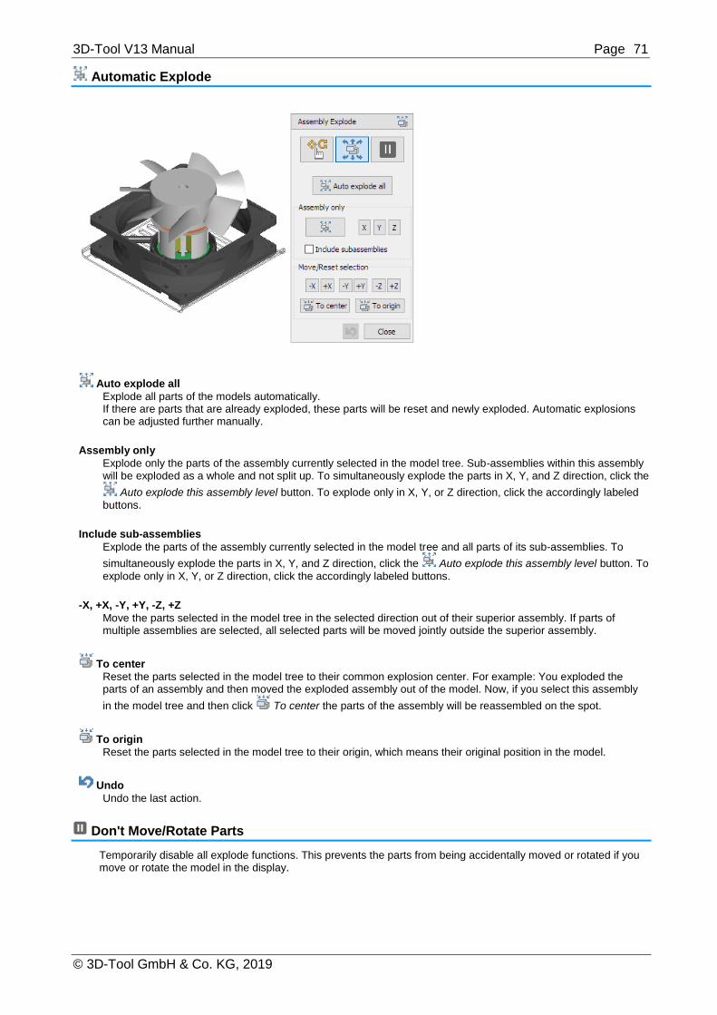
3D-Tool V13 Manual Page 71
© 3D-Tool GmbH & Co. KG, 2019
Automatic Explode
Auto explode all
Explode all parts of the models automatically. If there are parts that are already exploded, these parts will be reset and newly exploded. Automatic explosions can be adjusted further manually.
Assembly only
Explode only the parts of the assembly currently selected in the model tree. Sub-assemblies within this assembly will be exploded as a whole and not split up. To simultaneously explode the parts in X, Y, and Z direction, click the
Auto explode this assembly level button. To explode only in X, Y, or Z direction, click the accordingly labeled
buttons.
Include sub-assemblies
Explode the parts of the assembly currently selected in the model tree and all parts of its sub-assemblies. To
simultaneously explode the parts in X, Y, and Z direction, click the Auto explode this assembly level button. To
explode only in X, Y, or Z direction, click the accordingly labeled buttons.
-X, +X, -Y, +Y, -Z, +Z
Move the parts selected in the model tree in the selected direction out of their superior assembly. If parts of multiple assemblies are selected, all selected parts will be moved jointly outside the superior assembly.
To center
Reset the parts selected in the model tree to their common explosion center. For example: You exploded the parts of an assembly and then moved the exploded assembly out of the model. Now, if you select this assembly
in the model tree and then click To center the parts of the assembly will be reassembled on the spot.
To origin
Reset the parts selected in the model tree to their origin, which means their original position in the model.
Undo
Undo the last action.
Don't Move/Rotate Parts
Temporarily disable all explode functions. This prevents the parts from being accidentally moved or rotated if you move or rotate the model in the display.

3D-Tool V13 Manual Page 72
© 3D-Tool GmbH & Co. KG, 2019
Save Exploded View as Custom View
Save the exploded views of the model as Custom Views. This way you can restore them as needed and use them in Animations and in the Print and Create Picture settings. You can save Custom Views while working with the Explode tool. Also, there is a corresponding prompt when you exit the tool.
Note
If a view contains explosion data, you can switch between exploded and assembled view through the Show exploded button in the Display group. The explosion data of a view are retained until a new Custom View is selected.
Placement (not available with the Free Viewer and in EXE files)
Use the Placement tool to place and align your models.
The Placement tool is located in Toolbox group of the 3D-Mode tab.
Place Active Model
Select model
Only the active, red colored model will be positioned. To select a model, do one of the following:
Click << or >> until the wanted model is selected.
Click , and click a model in the display.
From
Use the From drop down list to choose the start reference to be used with the active model.
Auto reference: Move the cursor across the active model, and possible references are highlighted in blue.
Click to select a reference. You can choose from points, centers of circles, planes, edges and lines.
Model center: Use the center of the active model as start reference.
Model min: Use the minimal X,Y,Z - coordinate of the active model as start reference.
Model max: Use the maximal X,Y,Z - coordinate of the active model as start reference.
To
Use the To drop down list to choose the target reference for the active model.
Auto reference: Move the cursor across the models, and possible references are highlighted in blue. Click to
select a reference. You can choose from points, centers of circles, and planes.
Model center: Use the center of a model as target reference.
Model min: Use the minimal X,Y,Z - coordinate of a model as target reference.
Model max: Use the maximal X,Y,Z - coordinate of a model as target reference.
XY-plane: Use the XY-plane of the coordinate system as target reference.
XZ-plane: Use the XZ-plane of the coordinate system as target reference.
YZ-plane: Use the YZ-plane of the coordinate system as target reference.
X-axis: Use the X-axis of the coordinate system as target references.

3D-Tool V13 Manual Page 73
© 3D-Tool GmbH & Co. KG, 2019
Y-axis: Use the Y-axis of the coordinate system as target references.
Z-axis: Use the Z-axis of the coordinate system as target references.
Origin: Use the origin (0,0,0) of the coordinate system will be set as target reference.
When From and To are defined, you may align and/or translate the active model.
Align
Click on Align to position the active model. The Align button is only activated if the alignment is possible with the target references that are selected. Use the options Same and Opposite to set whether the alignment of the references will be in the same or the opposite direction. Axes, edges, and lines will be aligned perpendicular to a plane by default. The Parallel option activates parallel alignment.
Move Click on Move to reposition the active model. The move button is only activated if the move is possible with the target references that are selected. Use the All Axis, x, y, z option to determine which coordinates of the active model are affected.
Note
To Auto reference and pick centers of circles, it can be necessary to zoom close onto the wanted arc.
Tip
First align models, and then move them.
Auto Arrange Models
Arrange in line Click X,Y, or Z to arrange all models in a row along the corresponding axis.
Arrange in square
Click XY, XZ, or YZ arrange all models according to the corresponding plane. The goal is to arrange the models in the smallest square possible; however this depends on the number of models, as well as their size and form.
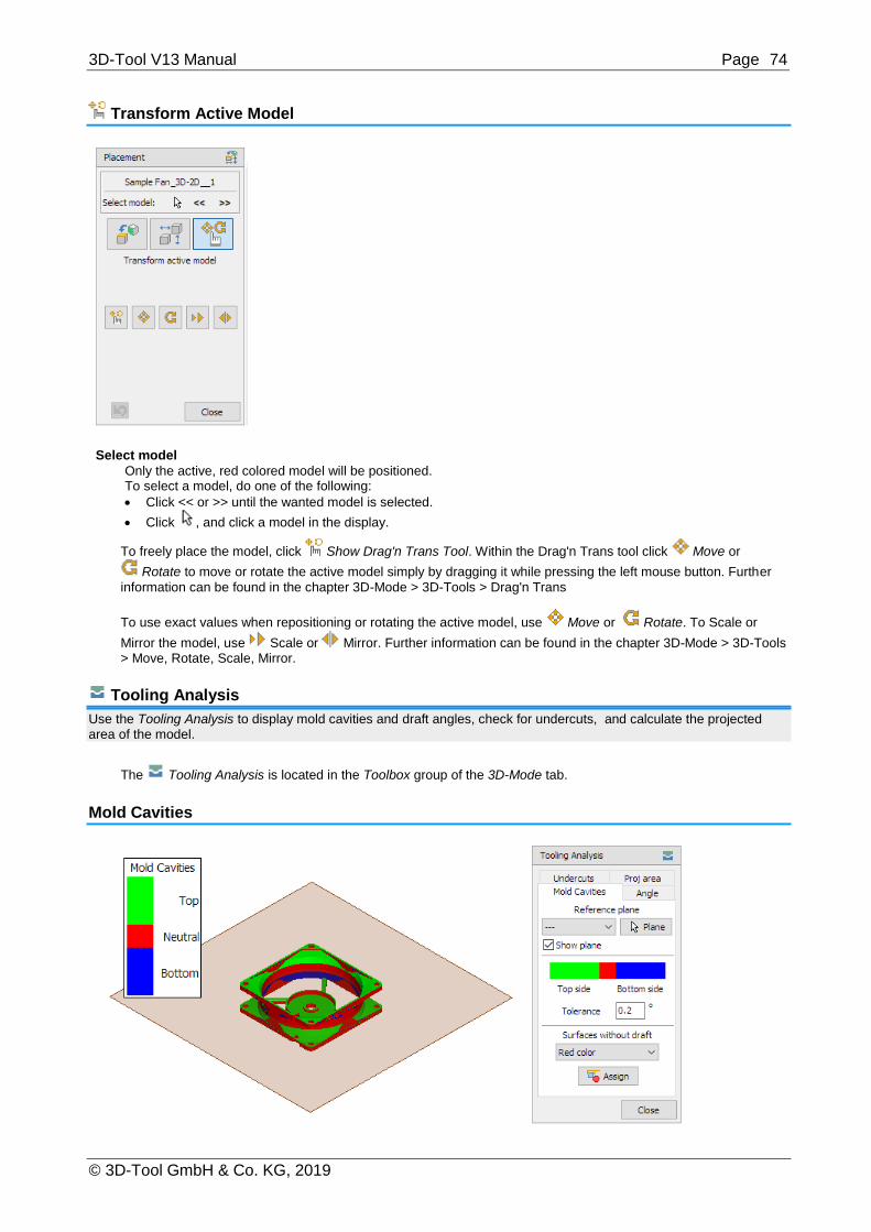
3D-Tool V13 Manual Page 74
© 3D-Tool GmbH & Co. KG, 2019
Transform Active Model
Select model
Only the active, red colored model will be positioned. To select a model, do one of the following:
Click << or >> until the wanted model is selected.
Click , and click a model in the display.
To freely place the model, click Show Drag'n Trans Tool. Within the Drag'n Trans tool click Move or
Rotate to move or rotate the active model simply by dragging it while pressing the left mouse button. Further
information can be found in the chapter 3D-Mode > 3D-Tools > Drag'n Trans
To use exact values when repositioning or rotating the active model, use Move or Rotate. To Scale or
Mirror the model, use Scale or Mirror. Further information can be found in the chapter 3D-Mode > 3D-Tools > Move, Rotate, Scale, Mirror.
Tooling Analysis
Use the Tooling Analysis to display mold cavities and draft angles, check for undercuts, and calculate the projected area of the model.
The Tooling Analysis is located in the Toolbox group of the 3D-Mode tab.
Mold Cavities

3D-Tool V13 Manual Page 75
© 3D-Tool GmbH & Co. KG, 2019
To choose the Reference plane, do one of the following:
From the drop down list select one of the standard planes XY, YZ, YZ
Click the Plane button or hold down [Shift] and click any plane on the model.
When the reference plane is selected, the faces of the model are displayed in different colors according to the mold cavities: By default: green - top, red - neutral, blue - bottom.
Show plane (Default: Active)
Show the reference plane as a transparent plane in the view.
Tolerance (Default 0.2)
Enter a tolerance angle for surface allocation. The tolerance angle is necessary because triangulated models are not 100% exact. Increasing the angle can harmonize the results of the analysis if the inaccuracy produces too many artifacts.
Surfaces without draft (Default: Red color)
Select the display of surfaces without draft from the drop down list:
Red color: Surfaces without draft angle are red.
Prefer top side: Surfaces without draft angle will be assigned to the top/green section.
Prefer none: Surfaces without draft angles are gray.
Prefer bottom side: Surfaces without draft angles will be assigned to the bottom/blue section.
Assign
Assign the current colors to the model and close the Tooling Analysis.
All colors of the model will be replaced with the colors of the Tooling Analysis. This cannot be undone and because the colors are a global property this change will affect all existing Custom Views.
If the Show plane option is active, the reference plane will be added as ReferencePlane_Tooling to the model tree.
Angle
To choose the Reference plane. do one of the following:
From the drop down list select one of the standard planes XY, YZ, YZ
Click the Plane button or hold down [Shift]. Click any plane on the model.
When the reference plane is selected, the draft angles are displayed in different colors.
Show plane (Default: Active)
Show the reference plane as a transparent plane in the view.
Angle (Default: 3.0)
Enter the maximum angle for the display of draft angles.
Direction (Default: Up)
Click the Direction button to designate whether draft angles opened up, down, or in both directions are shown.

3D-Tool V13 Manual Page 76
© 3D-Tool GmbH & Co. KG, 2019
Assign
All colors of the model will be replaced with the colors of the Tooling Analysis. This cannot be undone and because the colors are a global property this change will also affect all existing Custom Views.
If the Show plane option is active the reference plane will be added as ReferencePlane_Tooling to the model tree.
Undercuts
To choose the Reference plane, do one of the following:
From the drop down list, select one of the standard planes XY, XZ, YZ
Click the Plane button or hold down [Shift], and click any plane on the model.
As the reference plane is specified, the model is checked for undercuts. After the required calculations, the drafts and undercuts will be displayed in different colors. Default: green - top, blue - bottom, white - no draft, red - undercut.
Show plane (Default: Active)
Show the reference plane as a transparent plane in the view.
Tolerance (Default: 1.0)
Enter a tolerance angle for surface allocation. The tolerance angle is necessary because triangulated models are not 100% exact. Increasing the angle can harmonize the results of the analysis if the inaccuracy produces too many artifacts.
Assign
All colors of the model will be replaced with the colors of the Tooling Analysis. This cannot be undone and because the colors are a global property this change will also affect all existing Custom Views.
If the Show plane option is active, the reference plane will be added as ReferencePlane_Tooling to the model
tree.
Tip
The check for undercuts requires extensive calculations and will be always performed for all parts. An estimation of the time needed to perform the calculation will be displayed after starting the analysis.To cancel a running calculation, press [Esc], for example to delete not needed parts in the model tree.

3D-Tool V13 Manual Page 77
© 3D-Tool GmbH & Co. KG, 2019
Projected Area
This function calculates the surface area of all models that is projected onto one of the three standard planes. This, for example, is needed to calculate locking forces when making molds.
Choose on of the standard planes XY, XZ, YZ as Reference plane (Projection plane). When the reference plane is selected, the projected area is displayed in square units. For example, if the units of a model are millimeters in square millimeters.
Tip Use the Placement tool to align the model in the coordinate system.
Note
The projected area of a model is calculated by graphical projection which could cause some imprecision.
Model-Info
Use the Model-Info tool to display the volume, surface area, and dimensions of models and parts. Use the material database to calculate the weight of parts. Copy all information to other applications.
The Model-Info tool is located in the Toolbox group of the 3D-Mode tab.

3D-Tool V13 Manual Page 78
© 3D-Tool GmbH & Co. KG, 2019
Display and Copy Information
Selection
To display information select models, assemblies, or parts from the Model Tree. Alternatively browse through the Model Tree by clicking:
<< >> Next/previous model
<< >> Next/previous element
Units
The following units can be selected to be displayed:
mm - g (Millimeter and Gram)
mm - kg (Millimeter and Kilogram)
m - g (Meter and Gram)
m - kg (Meter and Kilogram)
in - g (Inch and Gram)
in - kg (Inch and Kilogram)
The units will be changed and the values will be converted. The amendment (original) means that the units match the default units as specified in the 3D-Tool preferences. The amendment (converted) means that there was a conversion between mm and inch.
Please note that the values are only reliably if the models loaded, are:
in a file format that provides information on the units used,
or its units suit the units set in the 3D-Tool Prefererences.
More information can be found in section Preferences > Common > Default Units.
Information
The following information is displayed for models and parts:
The number of parts of models and assemblies
The assigned material
The dimensions in X, Y and Z
The weight (requires an assigned material)
The volume
The surface area
The number of triangles
The number of openedges
If a part contains open edges, the information for this part as well as the assembly, in which the part is locatated, are displayed in red letters. The volume and thus the weight information is only accurate for closed parts and assemblies. Open edges and flipped surfaces may distort the results of the analysis. This problem can mainly accur when importing IGES files.
Copy information to Clipboard
Copy the information of the current selection to the Clipboard. For models and assemblies information on all contained parts will be copied. The contents of the Clipboard can be pasted into, for example, a Microsoft Excel spreadsheet.
Assign Materials / Weight Calculation
Assign material
To assign a material, first select a part or assembly in the Model Tree and then choose a material from the drop down list. If you assign a material to an assembly, the material will be assigned to all its parts. The green check
mark indicates that all parts of an assembly have a material assigned and the weight is calculated and displayed for all such parts and assemblies.
Create a new material
To create a new material open the material list, scroll down to its end and select ...New material ... In the following dialog enter the name and the density of the material and click OK. The material will be added to the list and will be assigned to currently selected parts and assemblies.

3D-Tool V13 Manual Page 79
© 3D-Tool GmbH & Co. KG, 2019
Edit the material database
To comfortably edit the material database, use the Material Database Editor. Start the editor by clicking the small [...] button top of the material list. [More information]
Note
The density values of the database delivered with 3D-Tool have been specified to the best of knowledge. However, because the values underlie a certain manufacturing variability we will take no responsibility for their accuracy.
Material Database Editor
Within the Model-Info tool, use the Material Database Editor to edit, delete or create materials that can be assigned to the parts of a model to calculate its weight.
The Materials Database Editor is part of the Model-Info tool located in the Toolbox group of the 3D-Mode tab.
Edit Materials
Edit the material list
To change an entry, click on the name or density of the material, and enter the new name or density.
To add a new entry, simply enter its name and density at the end of the list.
To delete an entry, just delete the name of the material.
Add model materials
If you open a 3D-Tool model (EXE/DDD), the model may contain materials not present in your material database. To transfer these materials to your database, click on Add model materials.
Load materials from file
To load materials from a materials file (*.txt), click Load. After selecting a material file, you will be asked if you
want to clear all default materials: Yes: All materials present will be cleared before loading the new materials. No: The new materials will be added to the current material list.
Save materials to file
To save materials to a material file (*.txt), click Save.

3D-Tool V13 Manual Page 80
© 3D-Tool GmbH & Co. KG, 2019
Note
The density values of the database delivered with 3D-Tool have been specified to the best of our knowledge. However, because the values underlie a certain manufacturing variability we will take no responsibility for their accuracy.
Structure of a Material File (*.txt)
Material files are simple text files that can be easily edited with an editor. 3D-Tool material files are structured as follows:
The materials are separated by a line break (return).
A material is specified as material name directly followed by its density in brackets: Material name(density), for example Alloy(2.70)
Animation (not available with the Free Viewer and in EXE files)
Use the Animation tool to create an animation of your Custom Views.
The Animation tool is located in the Presentation group of the 3D-Mode tab.
Basic Approach
An animation consists of multiple Custom Views that are used as key frames. To do so, take the following steps:
Generate different Custom Views of the model.
Activate the Animation tool.
Create a New Animation.
Add Custom Views as key frames to the animation.
Put the key frames in the wanted order and adjust their time of transition.
Example 1
Key frame 1 shows the front of the model. Key frame 2 shows the left side of the model. When the animation is run, the model will turn from the front to the left.
Example 2
Key frame 1 shows a regular view of the model. Key frame 2 shows an exploded view of the model. When the animation is run, parts of the model will move from their original position to their positions after the model has been exploded.

3D-Tool V13 Manual Page 81
© 3D-Tool GmbH & Co. KG, 2019
Create Animation
Animation
Choose an animation from the drop down list. If no animations were created, the list is empty.
New animation
Create a new animation.
Copy selected animation to new animation
Copy the current animation and create a new animation.
Rename animation
Change the name of the current animation.
Delete animation
Delete the current animation.
Animation key frames
The lists of the key frames in the current animation and their transition times in seconds. The list will be empty when a new animation has been created. To change the transition time of a key frame, double-click the transition time and enter the new time.
Custom Views
List of the available Custom Views. Use the Filter if there are orthogonal and perspective Custom Views. The transition between the two cannot be
animated and, thus, would be discontinues. So combining the two modes of display is useless. Choose a display mode from the drop down list.
Preview thumbnail
The thumbnail on the upper left side is a preview of currently selected Custom View or key frame. This makes it easier to select key frames or Custom Views.
Add selected Custom View to key frames
Add the views selected in the list of Custom Views as key frames to the animation. New key frames will be added to the end of the animation.
Remove selected key frame
Remove the selected key frame from the animation.
Move selected key frame up
Move the selected key frame up by one position on the list.
Move selected key frame down
Move the selected key frame down by one position on the list.
Change transition times
Change the transition time of a key frame by double-clicking the time and entering a new time (in seconds).
Start preview
Show a preview of the current animation in the preview thumbnail. To abort the preview, press Esc.
Play Animation
Click OK to exit the Animation tool. Now the animation can be played using the Play Animation button in the Presentation group. Animations will also appear at the end of the Custom Views list and can be started from there.
3D-Tool V13 Manual Page 82
© 3D-Tool GmbH & Co. KG, 2019
Export AVI
An animation can be exported as AVI video. To do so, take the following steps:
Click the Resolution button until the wanted resolution is displayed..
Click on Export AVI.
Select where you want to save the video, and enter the name of the video.
Select the Compressor (video codec) to be used. Depending on the compressor, it may be possible to make further adjustments through the Key Frame and Data Rate option and through the Configure button.
Click OK to start generating the video.
Depending on the compressor, the length of the animation, the resolution, and the capacity of the computer this process may take some time.
Note
A resolution lower than 800x600 pixels will not show fine lines, small details, and smaller text of, for example, annotations and dimensions.
Videocodecs
The AVI format is a container for various video codecs. All AVI files will have a *avi ending no matter what compressor was used. The codec has to be available so the video can be played. The following codecs have been tried; however, this is not an exhaustive list and only a short overview.
Full frames (uncompressed)
(Limited Suitability) Offers the best quality without lost data but creates a large file. It can be useful, if the video will be edited with a video editing software or further converted. Caution: Only files of up to 2 GB are supported.
Cinepak by Radius
(Suitable) Delivers good results and small files. The display is sharp and the color gradients will be displayed accurately.
Intel Indeo R3.2
(Not Suitable) Creates small files but an unfocused display with jagged color gradients.
Microsoft Video 1
(Limited Suitability) Very sharp display but poor color gradients and relatively large files.
Microsoft Video 9
(Suitable) Small files and decent quality; however, color gradients may be inaccurate.
DivX
(Very Suitable) The display is focused and color gradients are smooth. Even with high resolutions, small files are created. But, depending on the DivX version, there may be problems when exporting videos with high resolution.
MPEG-4
(Very Suitable) The display is focused and the transitions are smooth. Even with high resolutions, small files are created. Best results.
Model Compare (not available with the Free Viewer and in EXE files)
Use the Model Compare tool to graphically highlight the differences between two models.
The Model Compare tool is located in the Toolbox group of the 3D Mode tab.
Load and Select Models
Load two or more models that you want to compare. If the file names are identical, the models are renamed automatically. After the import, the models are listed in the model tree and overlap in the display.
Now activate the Model compare tool.
Select the two model you want to compare from the two drop down list, located at the top of the tool. If only two models are loaded, they are selected automatically.
Note
The 3D-Tool Model Compare is a graphical/visual comparison by dyeing the models in different colors and then laying one model on top of the other. Differences located inside the models can only by using cross section or by hiding parts.
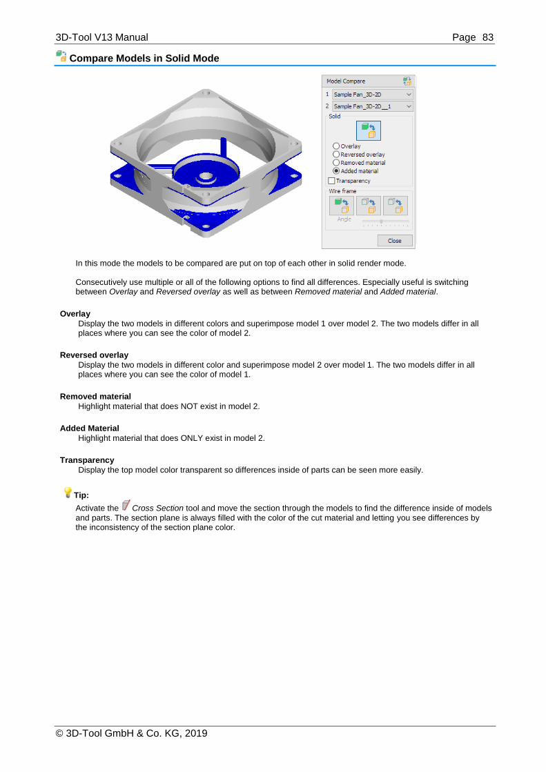
3D-Tool V13 Manual Page 83
© 3D-Tool GmbH & Co. KG, 2019
Compare Models in Solid Mode
In this mode the models to be compared are put on top of each other in solid render mode. Consecutively use multiple or all of the following options to find all differences. Especially useful is switching between Overlay and Reversed overlay as well as between Removed material and Added material.
Overlay
Display the two models in different colors and superimpose model 1 over model 2. The two models differ in all places where you can see the color of model 2.
Reversed overlay
Display the two models in different color and superimpose model 2 over model 1. The two models differ in all places where you can see the color of model 1.
Removed material
Highlight material that does NOT exist in model 2.
Added Material
Highlight material that does ONLY exist in model 2.
Transparency
Display the top model color transparent so differences inside of parts can be seen more easily.
Tip:
Activate the Cross Section tool and move the section through the models to find the difference inside of models
and parts. The section plane is always filled with the color of the cut material and letting you see differences by the inconsistency of the section plane color.

3D-Tool V13 Manual Page 84
© 3D-Tool GmbH & Co. KG, 2019
Wire Frame
Compare model 1 with model 2 as wire frame
Display model 1 solid and superimpose model 2 as wire frame over model 1. The two models differ in all places where you can only see the wires of model 2 or only the solid faces of model 1.
Reverse compare - Compare model 2 with model 1 as wire frame
Display model 2 solid and superimpose model 1 as wire frame over model 2. The two models differ in all places where you can only see the wires of model 1 or only the solid faces of model 2.
Compare both models as wire frame
Display both models as wire frame and superimpose model 2 over model 1. The two models differ in all places where you can see wires in the color of model 1.
Wire frame angle
Change the resolution of the wire frame. Move the slider left to lower the wire frame angle and to get a denser wire frame. Move the slider right to increase the wire frame angle and to get a lighter wire frame.
Note
The wire frame is based on the edges of the triangles that make up the model in the viewer. If you open models using different import settings (Chord height, Angle tolerance) the models may show deviations that do not exist.

3D-Tool V13 Manual Page 85
© 3D-Tool GmbH & Co. KG, 2019
Wall Thickness Analysis
Use the Wall Thickness Analysis to show the wall thicknesses of a model in different colors.
The Wall Thickness Analysis is located in the Toolbox group of the 3D-Mode tab.
Run a calculation
Calculating the wall thickness requires extensive calculations. An estimation of the time needed to perform the calculation will be displayed after starting the analysis. To cancel a running calculation, press [Esc], for example to adjust the calculation settings for a shorter calculation time.
Select model
The Wall Thickness Analysis can only display and analyze one model at a time. If there are multiple models, click << or >> until the wanted model is displayed.
At point
See the wall thickness at certain points on the model. This function is available without calculating the wall thicknesses.
Click At point and move the cursor across the model. The wall thickness at the position of the cursor will be
displayed.
Calculation Click Calculation to start a calculation based on the center of the generated triangles.
Note
Open edges and flipped surfaces may distort the results of the analysis.
Customize the Calculation
To get a preferably good result, the triangles that make up the model will be subdivided into smaller ones. The values in the Calculation section define the strength of subdivision.
A finer subdivision will increase the quality but also the calculation time.
A coarser subdivision will decrease calculation time but also the quality.
Remesh iterations (Default: 5)
Enter how many times the creation of the mesh will be repeated. A larger value will enhance the result but increase the time needed for the calculation. If "0" is entered, the edges of triangles will not be broken down further.
Max. edge length (Default: 2.5 mm / 0.098 inch)
Enter the maximum edge length a triangle may have until it is broken down into smaller triangles. A smaller value will enhance the result but increase the time needed for the calculation.

3D-Tool V13 Manual Page 86
© 3D-Tool GmbH & Co. KG, 2019
Shells/Parts separate (Default: active)
Select the Shells/Parts separate option to calculate the wall thicknesses for each shell/part separately. Disabling this option can improve the result for models that consist of individual faces.
Customize the Color Display
Adjusting the color display does not require a new calculation. So you try different settings after a calculation is done.
3 Colors
Choose the 3 colors option to display different wall thicknesses in the three colors blue, green, and red. In green areas the wall thickness lies within the specified Min and Max values, in blue areas below the Min value, and in red areas above the Max value.
Spectrum
Choose the Spectrum option to display the different wall thicknesses as a color spectrum between the specified Min and Max values.
Min. / Max.
Enter the minimum and maximum wall thickness for the color display.
Assign
Assign the current colors to the model and close the Tooling Analysis. By this all colors of the model will be replaced with the colors of the Tooling Analysis. This cannot be undone and because the colors are a global property this change will also affect all existing Custom Views.
Custom View Editor (not available with the Free Viewer and in EXE files)
Use the Custom View Editor to change the order and names of Custom Views.
The Custom View Editor is located in the Toolbox group of the 3D-Mode tab.
Filter
From the drop down list, choose the type of Custom Views to be displayed in the list of Custom Views:
All views
3D views
Orthogonal views
Perspective views
2D views

3D-Tool V13 Manual Page 87
© 3D-Tool GmbH & Co. KG, 2019
Views used in certain animations
List of Custom Views
Click a Custom view in the list to select it. The thumbnail, on the upper right side, shows a preview of the selected Custom View.
View is used in animation
If the selected Custom View is used in an animation, the name of the animation will be shown here. Deletion of the view will also delete the animation. Changing the names and order of Custom Views has no effect on animations.
Rename Custom View
Enter a new name (op to 50 characters) for the selected Custom View.
Delete Custom View
Delete the selected Custom View. If the Custom View is included in an animation, a warning will appear. Deleting the Custom View will also delete the animation.
Move selected Custom View up
Move the selected Custom View up by one spot on the list.
Move selected Custom View down
Move the selected Custom View down by one spot on the list.
OK
Apply all changes and exit the Editor.
Cancel
Discard all changes and exit the Editor.
Property Editor (not available with the Free Viewer and in EXE files)
Use the Property Editor to change the name, color, and transparency of parts. Save your changes for models with the same parts.
The Property Editor is located in the Toolbox group of the 3D-Mode tab.

3D-Tool V13 Manual Page 88
© 3D-Tool GmbH & Co. KG, 2019
Edit Properties
The property table
The property table has 4 columns:
Original name
The original names of assemblies and parts. Click an element to select it.
New name
Enter a new name for the selected element.
Color
Click the colored square to change the color of the selected element. Assemblies and multicolored parts (multicolored square) will be completely dyed in the new color.
Transp.
Click on the little blue square to turn / the transparency of the selected element. This function is only available with parts.
Notes
Changes will not be applied until you click Apply changes.
Elements without new names keep their original names.
Copy original name to new name
Copy the name of the selected element to the New name column.
All - Copy all original names to new names
Copy all original names to the to the New name column. Existing entries will be overwritten.
Highlight selected parts/assemblies (Default: Active)
Display selected parts and assemblies on the model in red. If inactive, double-click parts and assemblies to highlight them.
Apply changes
Click on Apply changes to apply the changes you have made.
Close
Leave the Property Editor.
Save And Load Properties
Save your changes for new versions of the model or models with the same part names. That way, you can load the changes to reapply them.
Save
Save the property table to a property file (*.pf).
Load
Load a property file (*.pf). Choose the properties (New name, Color, Transparency) to be transferred. Every element of the table whose original name matches a name in the property file will receive the properties stored in the file. You can continue to work on the table. Click on Apply changes to apply the changes you have made.
Notes
If the property file contains more than one entry of the same original name, all elements with this name will be assigned the properties of the first entry, and all other entries will be ignored.
For assemblies only the names will be transferred. However, all properties will be transferred for the parts of an assembly.
Characteristics of the property file (for experienced users)
The property file is a TAB separated text file that can be opened and edited with a text editor. Each entry starts with the original name of the element of which the properties are to be changed. The original name is followed, separated by a Tab, by the new name, color, transparency in the following syntax: OriginalName $N:NewName $C:$Color $T:- or +
Color stands for hexadecimal BGR color information in the form BBGGRR with a maximum of 6 characters.
$T: Minus - means transparency off, Plus + means transparency on.

3D-Tool V13 Manual Page 89
© 3D-Tool GmbH & Co. KG, 2019
Examples 611_Stator $N:Stator $C:$0000FF $T:+ Changes the name of the element 611_Stator to Stator, colors the element red and shows it transparent. Properties that are not to be changed can be omitted: 611_Stator $C:$0099FF Changes only the color for element 611_Stator.
Repair (not available with the Free Viewer and in EXE files)
Use the Repair tool to delete faces, fix inverted faces and open edges, create triangles, and move edge points.
The Repair tool is located in More tools in the Toolbox group of the 3D-Mode tab.
Basics
Select model
The Repair tool can only display and repair one model at a time. If there are multiple models, click << or >> until the wanted model is displayed.
Display
The Repair tool will show open edges in yellow and backs of triangles in red. This makes it easier to locate irregularities.
Tip
In the Display group activate the shade mode Shaded with Triangles. This makes the selection easier.
Delete
To delete faces, curves, or PMI click the Delete tab.
Single object select
The following selection modes are available:
Select surfaces, curves, and PMI
Select a single triangle
Select a plane surface
Select connected triangles
Select connected triangles in the same color
Move the cursor over the model. Details of the model will be highlighted in bright blue according to the selection mode. Click to select the highlighted elements. Selected elements will be highlighted in green color.
Marquee select
The following marquee selection modes are available:
Marquee select curves
Marquee select triangles

3D-Tool V13 Manual Page 90
© 3D-Tool GmbH & Co. KG, 2019
Marquee select PMI
Click into the display, hold the mouse button and drag the selection rectangle over the desired elements. All elements that are within the selection rectangle completely will be selected and highlighted in green color.
To delete selected elements click Delete selection. To remove the selection without deleting the elements click
on Reset selection.
Note
The marquee selection modes will select the visible elements and all elements behind them.
Normals
To invert surfaces click the Normals tab.
Single object select
The following selection modes are available:
Select a surface
Select a single triangle
Select a plane surface
Select connected triangles
Select connected triangles in the same color
Move the cursor over the model. Details of the model will be highlighted in bright blue according to the selection mode. Click to select the highlighted elements. Selected elements will be highlighted in green color.
Marquee select
The following marquee selection modes are available:
Marquee select triangles
Click into the display, hold the mouse button and drag the selection rectangle over the desired elements. All elements that are within the selection rectangle completely will be selected and highlighted in green color.
To delete selected elements click Invert selection. To remove the selection without inverting the elements click
on Reset selection.
Note
The marquee selection modes will select the visible elements and all elements behind them.

3D-Tool V13 Manual Page 91
© 3D-Tool GmbH & Co. KG, 2019
New (create new triangles)
Click the New tab to create new triangles.
Create a new triangle by picking three edge points. To make the selection easier, the edge points of the triangles are displayed. Click three edges points to select them. Click the Deselect button to reset an erroneous selection.
When the three points are selected, the new triangle will be created. Its orientation is calculated based on the adjacent triangles.
Move pt (Move points)
Click the Move pt tab to move edge points.
Move two edge points on top of each other, e.g. to close open edges. To make the selection easier, the edge points of the triangles are displayed. Click the edge point to be moved. Then click the edge point in target position. Click the Deselect button to reset a false selection.
Click the Confirm button to move the point.
Note
Moving points will delete triangles if two point of a triangle are on top of each other or all points are on one line.

3D-Tool V13 Manual Page 92
© 3D-Tool GmbH & Co. KG, 2019
Auto (automatic repair)
Click the Auto tab to automatically repair inverted faces and open edges.
The automatic repair tries to close open edges and turn inverted triangles.
Tolerance (Default 0.05mm / 0.002 inch)
Enter the distance value to be used for the automatic connection of open edges in the Tolerance field. The automatic repair tries to close all open edges based on the tolerance distance. Increasing the tolerance may close more open edges.
Connect edges
Click Connect edges to automatically close open edges.
Decide if you want to keep the part relations for the current model.
Yes: The repair will keep the current part assignments and names.
No: Based on newly connected edges, the repair may put the parts into a new arrangement. This may be useful if the parts consist of multiple shells, but the names of the parts may be lost.
Auto orientation
Click Auto orientation to automatically turn inverted triangles. The automatic orientation tries to assign the same orientation to all connected triangles.
Note
The automatic repair will not always completely close models with open edges or flipped surfaces. To get a "watertight" model more or less extensive manual repairs are needed
Tip
Execute Auto orientation and Connect edges multiple times in rotation to correctly orient as many faces as possible.

3D-Tool V13 Manual Page 93
© 3D-Tool GmbH & Co. KG, 2019
RP-Layout (not available with the Free Viewer and in EXE files)
Use the RP-Layout tool to place models on a platform for Rapid Prototyping Systems.
The RP-Layout tool is located in More tools in the Toolbox group of the 3D-Mode tab.
Select model
Except for Auto-Position always the active, red colored model will be positioned. To select a model, do one of the following:
Click << or >> until the wanted model is selected.
Click , and click a model in the display.
RP-System
Select the RP-system from the drop down list. Only the Standard system is available first, but you can create a new systems by using the Setup button.
Setup
Create a new RP-system by specifying its size and important parameters such as the distance between the models.[
Drag'n Trans
Move and rotate the model with the mouse.
Move
Move the model by entering x,y, and z-values. To move a copy of the model, activate the Create copy option.
Rotate
Rotate the model or a copy of it by choosing a rotation axis and entering an angle. To rotate a copy of the model, activate the Create copy option.
Scale
Scale the model.
Mirror
Mirror the model or a copy by choosing a mirror plane. To mirror a copy of the model, activate the Create copy option.
Auto position
Position the models according to the specifications of the RP-system automatically.

3D-Tool V13 Manual Page 94
© 3D-Tool GmbH & Co. KG, 2019
Align plane
From the drop down list To: choose the direction of the alighnment.
Then click Plane, and click a plane on the model.
Snap Z-min to
To move models to the minimal Z-position as specified in the according input field, do one of the following:
To move the active (red) model, click the Model button.
Click the All button to move all models to Z-min.
Undo
Undo the last action.
Setup RP-System (not available with the Free Viewer and in EXE files)
Use this assistant in the RP-Layout tool to create new RP-systems.
In the RP-Layout tool, click the Setup button to start Setup RP-System.
Select RP-System
Select a RP-system from the dropdown list. The properties of the selected RP-system will be displayed. If there are no customized systems, the list will only contain the Default system. Click OK to apply the selected system.
Delete
Delete the currently selected RP-System. The last remaining system cannot be deleted.
New
Opens the New RP-system input mask to specify the properties of the new RP-system.
New RP-System
Name
Enter a name for the new RP-System
x, y, z
Enter the values for the dimensions of the new RP-System. Values between 1 and 1000 are accepted .
Model Z min
To auto-postion models, enter the minimum distance of the models above the RP-platform. Values between 0.001 and 100 are accepted.
Space betw. models
To auto-postion models, enter the distance between models. Values between 0.001 and 100 are accepted.

3D-Tool V13 Manual Page 95
© 3D-Tool GmbH & Co. KG, 2019
Space to border
To auto-postion models, enter the distance of the models to the borders of the RP-system. Values are accepted between 0.001 and 100.
Fields displayed in platform
For the guide grid of the RP-platform enter the number of fields in X and Y direction. Values between 1 and 100 are accepted . Click the Create RP System button to create the new RP-System.
Create Reference Point
Use the Create Reference Point to to create apoint in the coordinate system, e.g. as reference fpr dimensions.
The Create Reference Point tool is located in More tools in the Toolbox group of the 3D-Mode tab.
Create Reference Point
Click the Create Reference Point tool in More tools in the Toolbox group of the 3D-Mode tab.
X, Y, Z Enter the coordinates for the reference point into the input fields X, Y and Z.
X, Y, Z Enter the rotation angle of the reference point's coordinate axes into the input fields X, Y and Z.
Color To select a color for the reference point, click the Point color button and pick a color from the color palette.
Size
From the drop down list, choose the size for the coordinate axes of the reference point.
Create
Create the reference point.
Undo
Undo the last action.

3D-Tool V13 Manual Page 96
© 3D-Tool GmbH & Co. KG, 2019
Apply xyz Coordinates of the Model
Click the Pick a reference button to get x,y, and z coordinates of model.
From the drop-down list, choose the wanted coordinates and the measuring point.
xyz - Circle center
xyz - Center of 3 points
xyz - Point on surface/curve
xyz - Vertex
x - Point on surface/curve
x - Vertex
y - Point on surface/curve
y - Vertex
z - Point on surface/curve
z - Vertex
Move the cursor across the model and possible measuring points will be shown in light blue. Click to select a point. The applicable coordinates of the point are applied to accordant input field.
Move
Use the Move tool to move models, assemblies, and parts.
The Move tool is located in More tools in the Toolbox group of the 3D-Mode tab.
Model Tree Selection
Select a model, an assembly, or a part in the Model Tree.
x, y, z
Enter the value of the movement in the x, y, and z input field.
Create copy
Create a copy of the selection, and move it.
Move
Execute the movement.
Undo
Undo the last movement.
Note
If you change the coordinates of parts (move, rotate, scale, mirror), it will affect your Custom Views.
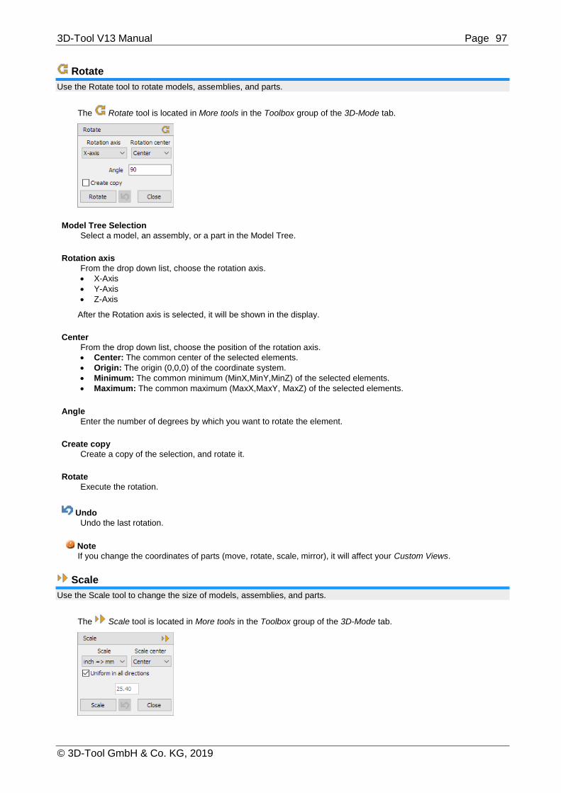
3D-Tool V13 Manual Page 97
© 3D-Tool GmbH & Co. KG, 2019
Rotate
Use the Rotate tool to rotate models, assemblies, and parts.
The Rotate tool is located in More tools in the Toolbox group of the 3D-Mode tab.
Model Tree Selection
Select a model, an assembly, or a part in the Model Tree.
Rotation axis
From the drop down list, choose the rotation axis.
X-Axis
Y-Axis
Z-Axis
After the Rotation axis is selected, it will be shown in the display.
Center
From the drop down list, choose the position of the rotation axis.
Center: The common center of the selected elements.
Origin: The origin (0,0,0) of the coordinate system.
Minimum: The common minimum (MinX,MinY,MinZ) of the selected elements.
Maximum: The common maximum (MaxX,MaxY, MaxZ) of the selected elements.
Angle
Enter the number of degrees by which you want to rotate the element.
Create copy
Create a copy of the selection, and rotate it.
Rotate
Execute the rotation.
Undo
Undo the last rotation.
Note
If you change the coordinates of parts (move, rotate, scale, mirror), it will affect your Custom Views.
Scale
Use the Scale tool to change the size of models, assemblies, and parts.
The Scale tool is located in More tools in the Toolbox group of the 3D-Mode tab.
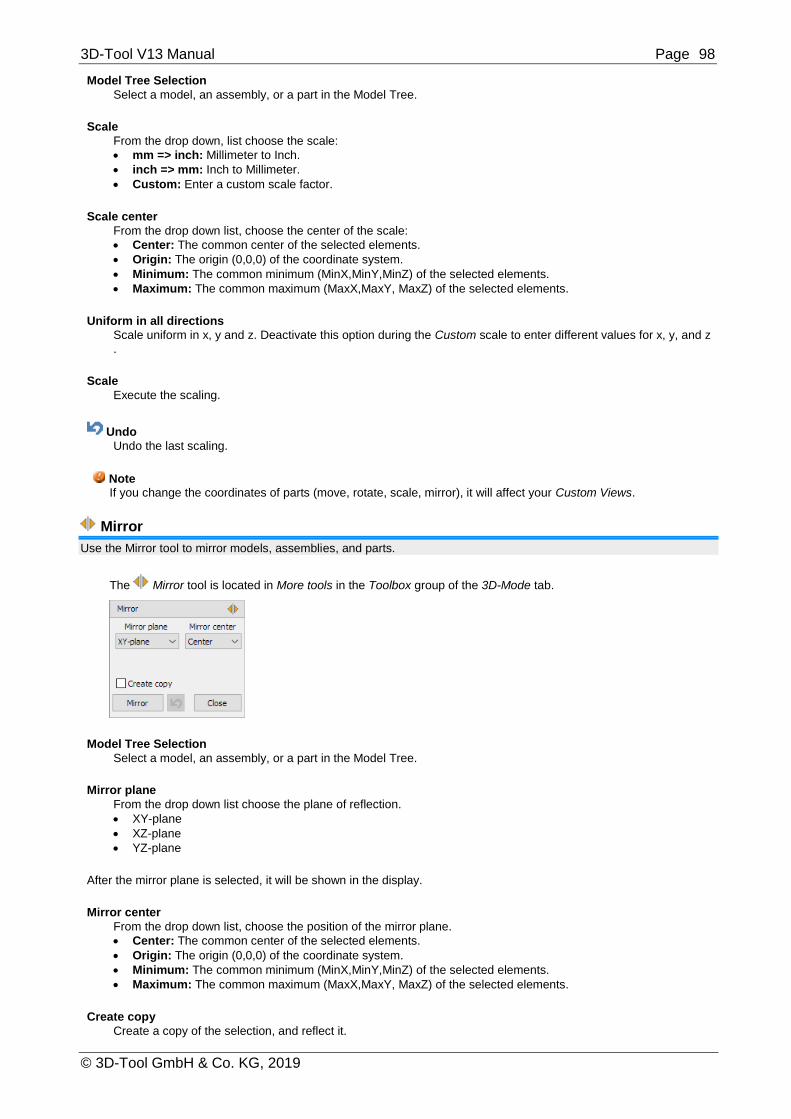
3D-Tool V13 Manual Page 98
© 3D-Tool GmbH & Co. KG, 2019
Model Tree Selection
Select a model, an assembly, or a part in the Model Tree.
Scale
From the drop down, list choose the scale:
mm => inch: Millimeter to Inch.
inch => mm: Inch to Millimeter.
Custom: Enter a custom scale factor.
Scale center
From the drop down list, choose the center of the scale:
Center: The common center of the selected elements.
Origin: The origin (0,0,0) of the coordinate system.
Minimum: The common minimum (MinX,MinY,MinZ) of the selected elements.
Maximum: The common maximum (MaxX,MaxY, MaxZ) of the selected elements.
Uniform in all directions
Scale uniform in x, y and z. Deactivate this option during the Custom scale to enter different values for x, y, and z
.
Scale
Execute the scaling.
Undo
Undo the last scaling.
Note If you change the coordinates of parts (move, rotate, scale, mirror), it will affect your Custom Views.
Mirror
Use the Mirror tool to mirror models, assemblies, and parts.
The Mirror tool is located in More tools in the Toolbox group of the 3D-Mode tab.
Model Tree Selection
Select a model, an assembly, or a part in the Model Tree.
Mirror plane
From the drop down list choose the plane of reflection.
XY-plane
XZ-plane
YZ-plane
After the mirror plane is selected, it will be shown in the display.
Mirror center
From the drop down list, choose the position of the mirror plane.
Center: The common center of the selected elements.
Origin: The origin (0,0,0) of the coordinate system.
Minimum: The common minimum (MinX,MinY,MinZ) of the selected elements.
Maximum: The common maximum (MaxX,MaxY, MaxZ) of the selected elements.
Create copy
Create a copy of the selection, and reflect it.

3D-Tool V13 Manual Page 99
© 3D-Tool GmbH & Co. KG, 2019
Mirror
Execute the reflection.
Undo
Undo the last reflection.
Note If you change the coordinates of parts (move, rotate, scale, mirror), it will affect your Custom Views.
Create Copy
Use the Create Copy tool to copy models, assemblies, and parts.
The Create Copy tool is located in More tools in the Toolbox group of the 3D-Mode tab.
Model Tree Selection
Select a model, an assembly, or a part in the Model Tree.
Create copy
Select Create Copy to copy the models, assemblies, or parts currently selected in the Model Tree:
Models: Selected models will be copied, and the copy will be added to the end of the Model Tree.
Assemblies: Selected assemblies will be copied, and the copy will be added at the end of the model.
Parts: Selected parts will be copied, and the copy will be added at the end of the model or the assembly
Drag'n Trans
Use this tool within the RP Layout and the Placement tool to easily move and rotate models with the mouse.
Move parts
Left-click on the selected model and hold down the mouse button to move the model. The x, y, and z-values of the translation and the position of the model center are shown while the model is moved. To make moving the model easier, deselect one or two directions for the moving (x, y, z) under Move direction.
Rotate part
Choose the x, y, z, or the virtual axis of the screen as rotation axis. Left-click on the model and hold down the mouse button to rotate the model. The angle of rotation is displayed while the model is rotated.
Don't move/rotate parts
Prevent the parts from being accidentally moved or rotated if you move or rotate the model in the view.
Undo
Undo the last movement/rotation.
Note If you change the coordinates of parts (move, rotate, scale, mirror), it will affect your Custom Views.

3D-Tool V13 Manual Page 100
© 3D-Tool GmbH & Co. KG, 2019
11. 2D Mode This section informs you about the 2D mode of 3D-Tool. The 2D mode features dimensions, markups, and tools to edit the elements of a drawing
To view 2D drawings, click the 2D-Mode tab or 2D Mode in the Mode group.
Zoom and Fit Drawings
Besides the scroll wheel or the middle mouse button, you can use the following functions to zoom in on and out of, and fit 2D-drawings.
The functions to zoom and fit the drawings are located in the Zoom group of the 2D-Mode tab.
Zoom All
Fit all visible drawings to the display. This function is also assigned to the function key [F4].
Zoom In
Zoom into an area. Click into the display, hold down the mouse button, and move the marquee across the area to be zoomed. This function is also assigned to the function key [F2].
Zoom Out
Zoom out of the view. Zoom in and out using the scroll wheel. This function is also assigned to the function key [F3].
Previous View
Undo the last zoom, move, or rotation of the view. This function is also assigned to the function key [F5].

3D-Tool V13 Manual Page 101
© 3D-Tool GmbH & Co. KG, 2019
Change the Background Color (2D)
Use a black, white, or colored background for your drawings.
In 2D Mode change the color of the background in the right info panel.
Black
Select the Black option to use a black background.
White
Select the White option to use a white background.
Custom color
Select the Custom color option to choose any color for the background. To choose a color, click the square button behind the option.

3D-Tool V13 Manual Page 102
© 3D-Tool GmbH & Co. KG, 2019
Change the Display of Lines (2D)
Display all lines of the drawing in black/white or as thin lines.
In 2D Mode, change the display of the lines in the Display group
Black/White Lines
Display all lines of the drawing in black or white, depending on the background color.
Thin Lines
Display all lines of the drawing with a width of 1pt. This may make it easier to see details in drawings with thick lines.

3D-Tool V13 Manual Page 103
© 3D-Tool GmbH & Co. KG, 2019
View: The Layer List (2D)
Use the View mode to view only a 2D drawing and to show/hide the layers of the drawing.
Click View in the right info panel to display the layer list.
Dimensions
This layer contains the dimensions added with 3D-Tool. To hide the layer, click . To show the layer, click .
Redlining
This layer contains the redline markups, annotations, and pictures added with 3D-Tool. To hide the layer, click the
icon. To show the layer, click .
Layers of the drawing
Depending on the loaded drawing, the layer list contains one or multiple layers.
To hide a layer, click . To show a layer, click .
Show/Hide
Show/Hide the layer currently selected in the layer list.
Show all layers Show all layers of the drawing. This will not show the layers Dimensions and Redlining if they are hidden.
Hide all layers
Hide all layers of the drawing. This will not hide the layers Dimensions and Redlining.

3D-Tool V13 Manual Page 104
© 3D-Tool GmbH & Co. KG, 2019
Annotate: Dimensions and Markups (2D)
Use the Annotate mode to add dimensions, redline-markups, annotations, and pictures.
Click Annotate in the right info panel to add dimensions and markups.
Add Dimensions (2D)
Measure distances, angle, radii and the length of lines.
To add dimensions, click Annotate in the right info panel.
Click Distance/Angle to measure distances and angles, or click the little black arrow in the button to select
another measure function.
Distance / Angle
Automatically measure the distance or the angle between two references. Move the cursor over the drawing. Elements of the drawing that can be used as references for measuring will be highlighted in blue, but you can also choose any arbitrary points. Select two references by clicking on them. Move the new dimension into the desired position, and click to fix it. In the following dialog, adjust the properties of the dimension, and click OK.
The type and position of the references determines whether the angle or position is measured.
Between two non-parallel lines the angle is measured.
Between two parallel lines the distance is measured.
Between two points the distance is measured.
Between a point and a line the distance is measured.
Note
Press [Esc] to cancel the operation.

3D-Tool V13 Manual Page 105
© 3D-Tool GmbH & Co. KG, 2019
Distance
Measure the distance between two references.
Move the cursor over the drawing. Elements of the drawing that can be used as references for measuring will be highlighted in blue, but you can also choose any arbitrary points. Select two references by clicking on them. Move the new dimension into the desired position, and click to fix it. In the following dialog, adjust the properties of the dimension, and click OK. The distance can be measured:
Between two points.
Between a point and a line.
Between two parallel lines.
Note
Press [Esc] to cancel the operation.
Distance In X- And Y-Direction
Measure the distances between two references in the direction of x or y. Move the cursor over the drawing. Elements of the drawing that can be used as references for measuring will be highlighted in blue, but you can also choose any arbitrary points. Select two references by clicking on them. Move the new dimension into the desired position, and click to fix it. In the following dialog, adjust the properties of the dimension, and click OK.
The distance can be measured:
Between two points.
Between a point and a line.
Between two parallel lines.
Note
Press [Esc] to cancel the operation.
Line Length
Measure the length of a line. Move the cursor over the drawing. Lines that can be used as references for measuring will be highlighted in blue. Select a line by clicking on it. Move the new dimension into the wanted position, and click to fix it. In the following dialog, adjust the properties of the dimension, and click OK.
Note
Press [Esc] to cancel the operation.
Radius
Measure the radius of a circle. Move the cursor over the drawing. Circles that can be used as references for measuring will be highlighted in blue. Select a circle by clicking on it. Move the new dimension into the desired position, and click to fix it. In the following dialog, adjust the properties of the dimension, and click OK.
Notes
Press [Esc] to cancel the operation.
If a circle cannot be selected, use Radius by 3 points.
Diameter
Measure the diameter of a circles.

3D-Tool V13 Manual Page 106
© 3D-Tool GmbH & Co. KG, 2019
Move the cursor over the drawing. Circles that can be used as references for measuring will be highlighted in blue. Select a circle by clicking on it. Move the new dimension into the desired position, and click to fix it. In the following dialog, adjust the properties of the dimension, and click OK.
Notes
Press [Esc] to cancel the operation.
If a circle cannot be selected, use Radius by 3 points.
Radius by 3 Points
Measure the radius of a circle defined by three points. Move the cursor over the drawing. Points of the drawing that can be used as references for measuring will be highlighted in blue, but you can also choose any points. Select three points by clicking on them. Move the new dimension into the desired position, and click to fix it. In the following dialog, adjust the properties of the dimension and click OK.
Note
Press [Esc] to cancel the operation.
Angle Between Two Lines
Measure the angle between two lines. Move the cursor over the drawing. Lines that can be used as references for measuring will be highlighted in blue. Select two lines by clicking on them. Move the new dimension into the desired position, and click to fix it. In the following dialog, adjust the properties of the dimension, and click OK.
Notes
Press [Esc] to cancel the operation.
Angle By 3 Points
Measure an angle defined by three points. Move the cursor over the drawing. Points of the drawing that can be used as references for measuring will be highlighted in blue, but you can also choose any arbitrary points. Select three points, of which the second point defines the angular point, by clicking on them. Move the new dimension into the desired position, and click to fix it. In the following dialog, adjust the properties of the dimension, and click OK.
Note
Press [Esc] to cancel the operation.
Angle By 4 Points
Measure an angle defined by four points. Move the cursor over the drawing. Points of the drawing that can be used as references for measuring will be highlighted in blue, but you can also choose any arbitrary points. Select four points, of which point 1 and 2 define the first arm and point 3 and 4 the second arm of the angle, by mouse click. Move the new dimension into the wanted position, and click to fix it. In the following dialog, adjust the properties of the dimension, and click OK.
Note
Press [Esc] to cancel the operation.

3D-Tool V13 Manual Page 107
© 3D-Tool GmbH & Co. KG, 2019
Adjust And Delete Dimensions
Move dimensions
Click the text of a dimension, hold down the mouse button, and move the dimension into the wanted position. Angle dimensions can be placed in any quadrant of the angle.
Change the properties of dimensions
Double-click the text of a dimension.
Scale: Choose the scale of the drawing to adjust the measured value.
Text field: Shows the text/value of the dimension. You can enter a custom text, but this will prevent the value
from being scaled.
Text: Change the text height and color.
Line: Change the thickness and color of the lines.
Arrow: Select an arrow head and change its length.
Tolerance: Enter tolerance values for the dimension.
Note
If common text heights appear extremely small or large, the units of the drawing do not correspond to the 3D-Tool default units. Options tab > Preferences group > Preferences > Common.
Delete dimensions
To delete a dimension, do one of the following:
Right-click the text of a dimension, and select Delete.
Click the Delete button in the right info panel, and then click the text of a dimension.
Move the cursor onto the text of a dimension, and press [Del] on the keyboard.
To delete all 2D dimensions and/or all 2D markups (redline markups, texts, pictures), click the Delete all
button in the right info panel.
Add Markups, Text and Pictures (2D)
Activate Annotate to create 2D markups. Use the second button to create various redline markups and insert pictures and texts.
To add markups, text, and pictures, click Annotate in the right info panel.
Click Arrow to add an arrow markup, or click the little black arrow in the button to select another function.

3D-Tool V13 Manual Page 108
© 3D-Tool GmbH & Co. KG, 2019
Arrow
Add an arrow. Click to select the starting point, hold down the mouse button, and move the arrow to the end point.
Sketch
Add a sketch. Click on the drawing, hold down the mouse button, and draw with the cursor.
Circle
Add a circle. Click into the drawing, hold down the mouse button, and drag the circle to the wanted size.
Note
Actually, an ellipse is created and the circle only constitutes the ideal case of uniformly dragging the ellipse in the x- and y-direction.
Rectangle
Add a rectangle. Click into the drawing, hold down the mouse button, and drag the rectangle to the wanted size.
Oval
Add an oval. Click into the drawing, hold down the mouse button, and drag the oval to the wanted size.
Cloud
Add a cloud. Click into the drawing, hold down the mouse button, and drag the cloud to the wanted size.
Add Text
Add a text. Click into the drawing. Choose the text height and color, enter the text, and click OK.
Add Picture
Add a PNG, JPG or BMP picture. Click into the drawing, hold down the mouse button, and drag the rectangle to the wanted size. Release the mouse button, and load an image.
Adjust and Delete Markups, Text and Pictures
Move markups, text and pictures.
Click a markup, text, or edge of a picture, hold down the mouse button, and move the object into the wanted position. For arrow markups, you can also move the starting and end point.
Scale markups and pictures
Move the cursor onto the line of a markup or the edge of a picture. Press and hold [Ctrl] and the left mouse button. Move the mouse to scale the object.
Change the lines of markups
Double-click a markup. Change the thickness and color of the line. For arrow markups, you can also change the length of the arrow head.
Change text
Double-click a text. Change text height and color or enter new text.
Replace pictures
Double-click the edge of a picture, and select a new picture to be loaded.
Delete markups, text and pictures
Right click a markup, a text or the edge of a picture. Select Delete.
Move the cursor on a markup, text or edge of a picture. Press [Del] on the keyboard.
Click the Delete button in the right info panel, and then click a markup, text or the edge of a picture.

3D-Tool V13 Manual Page 109
© 3D-Tool GmbH & Co. KG, 2019
To delete all 2D dimensions and/or all 2D markups (redline markups, texts, pictures), click the Delete All button in the right info panel.
Note
If common text heights appear extremely small or large, the units of the drawing do not correspond to the 3D-Tool default units. Options tab > Preferences group > Preferences > Common.
2D-Tools
Use the 2D-Tools mode to edit the elements of the drawing and the markups, texts and pictures added with 3D-Tool.
To use the 2D-Tools, click the 2D-Tools button in the right info panel.
Select
Click Select or press and hold the [Shift] key on your keyboard. The cursor changes to a crosshair. Now you
can select any element in the display. This can be elements of the drawing as well as 3D-Tool dimensions and markups.
Click on an element and the element will be highlighted and added to the selection.
Click on the drawing, hold down the mouse button, and move the marquee select across the wanted elements. Release the mouse button. All elements that are totally or partially covered by the marquee rectangle are highlighted and added to the selection.
To remove a selection, click Deselect.
Delete Selection
Delete the selected elements.
Change Color Of Selection
Choose a new color for the selected elements. If nothing is selected, but there is a layer of the drawing selected in the layer list, you will be asked if you want to change the color of the complete layer.

3D-Tool V13 Manual Page 110
© 3D-Tool GmbH & Co. KG, 2019
Move Selection
Move the selected elements. Click on the drawing, hold down the mouse button, and move the selection to the wanted position. If nothing is selected, you will be asked if you want to move the origin of the drawing to the coordinates (0,0).
Scale Selection
Scale the selected elements. Select the scale to be used:
inch => mm.
mm => inch.
Custom: Enter a scale.
If nothing is selected, you will be asked whether or not you want to scale the whole drawing.
Change Text Element
Edit a text element of the drawing.
If there is no text element selected yet (see above Select) click on a text element of the drawing. If a text element is selected a small input box will be displayed in the right info panel to edit the text.
Click OK to apply your changes.
Click Cancel to leave the text as it is.
Notes
Text markups/annotations added using 3D-Tool cannot be edited with this function.
Text made up of curves or text imported as curves cannot be edited.

3D-Tool V13 Manual Page 111
© 3D-Tool GmbH & Co. KG, 2019
12. Options This section informs you about the 3D-Tool settings that let you adjust 3D-Tool to your personal needs.
The Options Tab
Use the Options tab to adjust 3D-Tool to your needs, activate 3D-Tool licenses, and get information on the program version and available updates.
Licensing
Data Privacy
Show the 3D-Tool data privacy statement.
License Terms
Show the 3D-Tool End User License Agreement.
Licensing (not available in the Free Viewer)
Show the licensing dialog to request and enter 3D-Tool License and Demo Keys..
3D-Display Options
Change Background
Change the color and the gradient of the 3D-background.
Gradient background
Display the background in a gradient that begins with the selected base color.
Top color intensity
The slider adjusts the color intensity of the top color. Move it up for a brighter and down for a darker color.
Set as default
Designate the current background as default.
Change color
Set a base color for the background.
Update screen
Apply all changes to the background. This way you can preview your settings without exiting the background dialog.
Change Wire Frame Angle (Default: 20) Change the wire frame angle used for the display modes: Shaded/Edges, Wire Frame and Hidden Line. A line will be displayed at the edge between two triangles if their angle is greater than the wire frame angle. A small angle will create more lines than a large angle. The Set as default button designates the current wire frame angle as default.
Adjust Smoothing
Recalculate the smoothing for all models. To do so, enter an angle larger than "0". The transitions among the triangles will be smoothed if the angle between the triangles is smaller than the smooth angle. The larger an angle, the more the models will be smoothed. To prevent the models from being smoothed, reduce the angle to 0°.
Note:
The recalculation of the smooth vector overwrites the current smooth vectors and cannot be undone.
Preferences
The functions to change the language, to activate hardware acceleration, and to change the 3D-Tool preferences are located in the Preferences group of the Options tab.

3D-Tool V13 Manual Page 112
© 3D-Tool GmbH & Co. KG, 2019
Change Language
Change the language of 3D-Tool. Choose one of the available languages from the drop down list. The language will change immediately.
Preferences
Change the 3D-Tool preferences to your needs. A detailed description on all preferences can be found in the Preferences section of this manual.
Hardware Acceleration
Activate hardware acceleration for the current session. This will speed up the display. All changes in 3D-Tool and other open programs should be saved before activating the hardware acceleration for the first time. If there are strange effects after activating the hardware acceleration, it cannot be used.
Parts of the user interface are not shown or not shown correctly.
The model is not or is only partly shown.
The program crashes.
The program cannot be started.
In this case switch off the hardware acceleration or restart 3D-Tool. This is not a software bug but the result of an incompatible implementation of the OpenGL interface in the driver of the graphics card.
If there are no problems, the hardware acceleration can be set permanently through: Options tab > Preferences group > Preferences button > Hardware.
If there are unexpected problems after this permanent activation and if you cannot switch off the acceleration, e.g. because 3D-Tool refuses to start then turn off the Hardware acceleration through: Windows Start > Programs > 3D-Tool V13 > Tools > OpenGl-Accelaration_Off.
Note
With 3D-Tool EXE-files, the hardware acceleration can be activated in the starting dialog of the EXE file or after
start-up in the Options tab by clicking Hardware acceleration.
Tip
Updating the driver of the graphics card will often eliminate problems during the hardware acceleration.
Info
About 3D-Tool
See information about 3D-Tool, such as the program version, the serial number, and license type.
Tip of the Day
Show the Tip of the Day.
Check for Updates
Check online for a newer program version. This requires an internet connection.
Help
Help ( F1)
Open the 3D-Tool Help. The Help can always be opened by pressing the F1 Key.
Manual
Open the 3D-Tool manual. The manual contains the complete 3D-Tool Help. To view the manual, the Adobe Reader is required.
Quick Reference
Open the 3D-Tool Quick Reference Card. The Quick Reference gives a brief overview of the 3D-Tool user interface. To view the Quick Reference, the Adobe Reader is required.

3D-Tool V13 Manual Page 113
© 3D-Tool GmbH & Co. KG, 2019
Preferences
This section informs you about the default settings of the 3D-Tool tools and functions.
The Preferences are located in the Preferences group of the Options tab.
Common
Common default settings such as the program language and the default units.
Options tab > Preferences group > Preferences > Common.
Program language (Default: System language)
Select one of the available languages for program start-up. Choosing System language will start 3D-Tool in the system language of Windows, if available, otherwise in English.
Windows title bar (Standard: Acive)
Use a standard Windows 7 style title bar for the 3D-Tool window. Switch off to display the title bar in Windows 8 or Windows 10 style.
Note
Without the Windows title bar the automatic snapping/resizing of the window to the display borders (AERO SNAP) is not available.
Windows Styles (Default: Windows 10)
Specifies the color and style of the 3D-Tool title bar and ribbon menu.Available styles are:
Windows2010Silver
Windows2010Blue
Windows2010Black
Windows7
Windows10
Windows10Dark
Save window size at end of program (Default: Active)
When closing 3D-Tool, save the window size and position for the next program start-up.
Allow start on each monitor (Default: Inactive)
By default a 3D-Tool window will start up on the primary display of the computer. Set this option if you want 3D-Tool to start up on the display on which the last 3D-Tool window had been closed.
Default units (Default depends on Windows settings: mm for metric, inch for US system units) Set the default units of measurement (mm or inch).
Models of the following files will be scaled to the 3D-Tool default units during import:

3D-Tool V13 Manual Page 114
© 3D-Tool GmbH & Co. KG, 2019
STEP, IGES, VDA, SAT, JT and PARASOLID.
Native files from CATIA, Pro/Engineer, Creo, Inventor, Solidworks, SolidEdge and UG.
Triangulated 3D models (STL, SLP, VRML, etc.), 3D-Tool models (DDD, EXE) and 2D drawings, do not contain information on the units used and will be imported without scaling. If the units of the model or the drawing deviate from the standard 3D-Tool units, this may lead to unexpected result for the following functions:
Incorrect assignment and conversion of the units in the Model-Info tool.
Inappropriate specification of the Edge length for the Wall Thickness Analysis.
Too small or large Text height of 2D dimensions and 2D texts.
In this case, change the 3D-Tool default units to the units of the file.
Animation time (Default: 1.00)
Set the time in seconds for:
The animation of the 3D-view, e.g. when Custom Views or standard views are selected. If a 0 is entered, there will be no animation.
The transition time of new key frames in the Animation tool.
Custom Views: Show undefined parts (Default: Inactive)
Instead of hiding them, show newly loaded parts in existing Custom Views.
Automatically check for updates (Default: Active)
During the program start-up, check if there is a new program version. You will receive an according message. Download and install new versions from www.3D-Tool.com.
Reset hidden dialogs
Reset all dialogs that are hidden, by selecting Don't show this message again.
3D - Display
Default settings of the 3D Display such as the display of back faces and open edges.
Options tab > Preferences group > Preferences > 3D - Display.
Shade mode (Default: Shaded)
Select the shade mode of the models at program start-up
Shaded
Display the models shaded.
Shaded with edges
Display the models shaded with black edges
Fast move (Default: Auto)
Select the display of parts being moved with the mouse.
On

3D-Tool V13 Manual Page 115
© 3D-Tool GmbH & Co. KG, 2019
Display parts being moved as wire frame to speed up the display.
Off
Display parts being moved in the current render mode during movement. When slow computers are used, large and complex models may not move smoothly.
Auto
Display parts being moved automatically as wire frame if the number of frames displayed per second drops below the FPS threshold.
Back faces (Default: None)
Select the display of back faces at program start-up
Same
Display shaded faces with same colored back faces.
Red
Display shaded faces with red back faces.
None
Display shaded faces without back faces. This speeds up the display.
Display open edges (Default: Inactive)
Display open edges at program start-up.
Display coordinate system (Default: Inactive)
Display the coordinate system at program start-up.
Display 3D-compass (Default: Active)
Display the 3D-compass at program start-up
Rotate around screen center (Default: Active)
Use the center of the screen as the center of rotation when models are rotated with the mouse. Otherwise, the center of all models will be used.
Perspective view (Default: Inactive)
Display the models in perspective view at program start-up.
Note
Rotate around screen center does not work with the perspective view.
Global shade mode resets local part settings (Default: Active)
Reset all parts to the render mode of the display when it is changed. If this option is not active, only the display mode of such parts that do not have an individual render mode assigned is changed.

3D-Tool V13 Manual Page 116
© 3D-Tool GmbH & Co. KG, 2019
3D - Model Tree
Default settings of the Model Tree.
Options tab > Preferences group > Preferences > 3D - Model Tree.
Size (Default: Double size)
Select the size of the Model Tree at program start-up
Normal size
Display the Model Tree in normal width.
Double size
Display the Model Tree in double width.
Sort shells while loading STL or SLP files (Default: Active)
Sort the shells of the models while loading STL and SLP files. Select the type and direction of sorting.
By number of triangles.
By volume.
By volume of bounds (Default).
By number of open edges.
Up / Down
Highlight while moving mouse over parts (Default: Active)
Highlight parts and assemblies when moving the mouse over their names in Model Tree.

3D-Tool V13 Manual Page 117
© 3D-Tool GmbH & Co. KG, 2019
3D - Color
Default settings of transparency, brightness, and light position.
Options tab > Preferences group > Preferences > 3D - Color.
Transparency/Brightness
Set the values of transparency and brightness at the program start-up.
Transparent ... Solid (Default: 70%)
Opacity of parts that are displayed transparent.
Dull ... Shiny (Default: 50%)
Brightness of parts that are displayed shaded.
Light (Default: Light at 4/4)
Drag the yellow light spot to set the default light position.
3D - Section
Default settings for 3D cross sections.
Options tab > Preferences group > Preferences > 3D - Section.

3D-Tool V13 Manual Page 118
© 3D-Tool GmbH & Co. KG, 2019
Show cross section controls in front of geometries (Default: Inactive)
Always display the section controls in front of the model, even if they are located behind the model.
Show section line while move section (Default: Active)
Do not hide the section line while moving the cross section.
Section line color (Default: Red)
Choose a color for the section line.
3D - Annotations
Default settings of dimensions and annotations.
Options tab > Preferences group > Preferences > 3D - Annotations.
Foreground color (Default: Black)
Choose the text color of new dimensions/annotations.
Background color (Default: Light yellow)
Choose the color of the text box of new dimensions/annotations.
Line color (Default: Red)
Choose the color of the lines of new dimensions/annotations.
Text height (Default: 14)
Choose the text height of new dimensions/annotations.
Distance: Decimal format (Default: 0.12 - 2 places for mm, 0.123 - 3 places for inch)
Choose the number of decimal places used with newly measured distances.
Angle: Decimal format (Default: 0.12 - 2 places)
Choose the number of decimal places used with newly measured angles.
Stay on top (Default: Inactive)
Always display new dimensions/annotations in front of the model, even if they are located behind the model.
Use leading text description (Default: Inactive)
Display a leading text description for the dimension type.

3D-Tool V13 Manual Page 119
© 3D-Tool GmbH & Co. KG, 2019
3D - Import Basic
Default settings used with the Basic 3D Import.
Options tab > Preferences group > Preferences > 3D - Import Basic.
Calculate smooth vectors for files with flat triangles (Default: Inactive)
Calculate smooth vectors while loading files that do not contain smooth vectors. To do so, set Smooth angle. Angles between 20 and 35 degrees deliver the best results.
Load *_s.stl files in one shell (Default: Active)
Load STL-Support files (*_s.stl) as one shell.
Load colored STL files as colored (Default: Active)
Load the colors from STL files that contain color data.
Assign color to non-colored STL files (Default: Active)
Automatically assign a new color to every STL file that does not contain color data.
Select a color for all non-colored STL files (Default: Inactive)
Assign the selected color to all STL files that do not contain color data. Click the square button to select the color.

3D-Tool V13 Manual Page 120
© 3D-Tool GmbH & Co. KG, 2019
3D - Import Advanced/Premium
Default settings used with the advanced and premium 3D import.
Options tab > Preferences group > Preferences > 3D - Import Adv/Prem.
Show import settings dialog (Default: Active)
Show the import settings dialog when loading 3D-CAD files.
Load hidden entities (Default: Inactive)
Activate the Load hidden entities option in the import settings.
Load face boundaries (Default: Inactive)
When loading models, load their face boundaries as curves.
Default import settings (Default: High Quality)
Use one of the following presets for the tesselation settings in the import settings dialog.
Custom
High Quality
Low Quality
CAD Graphical data
Quick(BREPs only)
NoHeal(BREPs only)
Custom tessellation settings
Set the values for the Custom preset in the import settings dialog.
Chord height (Default: 0,05 mm / 0.002 inch)
Enter a value for the chord height.
Angle control (Default: 20)
Enter a value for the angle control.
Premium-Importer (3D-Tool Premium only)
Use Premium-Importer for STEP, IGS, VDA, SAT and Parasolid (Default: Active)
Use the Premium Importer with STEP, IGS, VDA, SAT, and Parasolid files. Otherwise the Advanced Importer will be used with these files.
Show import warnings and errors (Default: Active)
After loading, shows import errors and warnings, e.g. missing parts and information on non-supported formats.
Use black color for white PMI
During import, change the color of white colored product manufacturing information to black to increase their visibility

3D-Tool V13 Manual Page 121
© 3D-Tool GmbH & Co. KG, 2019
3D - Publish / Export
Default settings for publishing and saving data.
Options tab > Preferences group > Preferences > 3D - Publish/Export.
Default file as short message for publish EXE/DDD (Default: Empty)
Enter the path and file name of a text file (*.txt) that is used as short message for publishing every time an EXE/DDD file is published. The text is limited to 2000 characters and can be edited before the file is published.
Overwrite STL files without confirmation (Default: Inactive)
When saving models as STL files overwrite already exiting files without any warning.
Save STL files with color information (Default: Active)
Save the colors of the model with STL files. The files can be used with any other program. But since there is no standard of STL colors, the colors may not be displayed correctly.
Include smooth groups in 3DS files (Default: Inactive)
When 3DS files are saved, create smooth groups based on the angle set in Angle to create smooth groups. (Default 45)

3D-Tool V13 Manual Page 122
© 3D-Tool GmbH & Co. KG, 2019
2D - Display
Default settings of the 2D display when the program is started.
Options tab > Preferences group > Preferences > 2D - Display.
Resolution for curves and circles (Default: 32)
Set the value of the arc resolution. A large value will result in a better display of arcs but reduce the speed of the display.
Background (Default: Black)'
Choose the color for the background at program start-up
Black
Use a black background.
White
Use a white background.
Custom color
Choose any color for the background. Click the square button to choose the color.
Use antialiased lines (Default: Inactive)
Smooth the display of lines in the drawing.
Use thin lines (Default: Inactive)
At program start-up, show all lines of the drawing with a width of 1 point.

3D-Tool V13 Manual Page 123
© 3D-Tool GmbH & Co. KG, 2019
2D - Annotations
Default settings of new 2D Annotations and Dimensions.
Options tab > Preferences group > Preferences > 2D - Annotations.
Text height (Default: 14)
Choose the text height of new Dimensions.
Color (Default: Red)
Choose the text color of new Dimensions.
Line thickness (Default: 1)
Choose the width of lines of new Dimensions.
Color (Default: Red)
Choose the color of lines of new Dimensions.
Arrow (Default: inner triangle)
Choose the arrow head of new Dimension.
Length (Default: 3)
Choose the length of an arrow head of new Annotations and Dimensions.
Distance: Decimal format (Default: 0.12 - 2 places for mm, 0.123 - 3 places for inch)
Choose the number of decimal places used with newly measured distances.
Angle: Decimal format (Default: 0.12 - 2 places)
Choose the number of decimal places used with newly measured angles.
Redline markups
Line thickness (Default: 3)
Choose the width of new redline markups.
Color (Default: Red)
Choose the color of a new redline markups.

3D-Tool V13 Manual Page 124
© 3D-Tool GmbH & Co. KG, 2019
Print / Picture / Capture
Default settings for print-outs, pictures and captures.
Options tab > Preferences group > Preferences > Print/Picture/Capture.
Print /Picture
Change the default settings for print-outs and pictures.
Improve quality (Antialias) (Default: Active)
Use antialias when printing or creating a picture.
Jpeg quality (Default: 90)
Set the quality of JPG pictures that were created with 3D-Tool. Possible values are between 30 and 100. Larger values will result in better quality but also in a larger file.
Preferred print format (Default: Landscape) Choose the preferred format for printing: Landscape or Portrait
Capture to Clipboard
Settings for capturing sections of the screen to the Clipboard.
Use white background (Default: Inactive)
Draw a black frame around the captured screenshot.
Use antialias (Default: Active)
Use antialias on the captured screenshot.
Include frame (Default: Inactive)
Draw a black frame around the captured screenshot.

3D-Tool V13 Manual Page 125
© 3D-Tool GmbH & Co. KG, 2019
Hardware
Activate the hardware acceleration and adjust the zoom speed of the mouse wheel.
Options tab > Preferences group > Preferences > Hardware.
Enable Hardware Acceleration (Default: Inactive)
Activate the OpenGL hardware acceleration of the graphics card at program start-up. In rare cases, problems may occur after the hardware acceleration is activated.
Enable OpenGL 3.3 (Default: Inactive)
When the hardware acceleration is enabled, the OpenGL 3.3 hardware acceleration of the graphics card can also be activated to optimize the display performance. In rare cases, after the activation some older graphic drivers may show incorrect shading or colors.
Note
When enabling the OpenGL 3.3 option for the first time, you can perform a short, one-minute test that tests the display performance of the graphics card. This test is recommended.
Mouse wheel zoom
Set the speed of the zoom when using the scroll wheel.

3D-Tool V13 Manual Page 126
© 3D-Tool GmbH & Co. KG, 2019
File Associations
The file extensions associated with 3D-Tool.
Options tab > Preferences group > Preferences > File Associations.
Check all file formats you want to associate with 3D-Tool, and click Apply. The list contains all file formats that are supported by 3D-Tool. Non-selectable (gray colored) file formats are not available with your 3D-Tool Version/License.
Notes
Once a file association is set, it will be activated until it is overwritten by another program.
To set a file connection, you have to have administrative rights. Starting with Windows Vista, you will be asked to confirm and possibly to re-enter the administrative password by the User Account Control (UAC).
File associations set by a Windows user manually may fail to be changed by 3D-Tool.

3D-Tool V13 Manual Page 127
© 3D-Tool GmbH & Co. KG, 2019
13. Additional Help Use the following additional help when working with 3D-Tool.
3D-Tool Quick Reference
The 3D-Tool Quick Reference Card gives a quick overview of the user interface of 3D-Tool: Windows Start > Programs > 3D-Tool V13 > Quick Reference.
3D-Tool Manual
This help is available as a PDF manual: Windows Start > Programs > 3D-Tool V13 > Manual.
3D-Tool tool tips
When the cursor is moved onto a button (e.g. on the Ribbon Menu) and remains there a moment, a short description of the function is displayed.
3D-Tool website
Go to our website www.3D-Tool.com to find the newest information about 3D-Tool.

3D-Tool V13 Manual Page 128
© 3D-Tool GmbH & Co. KG, 2019
14. 3D-NativeCAD Converter (only available with 3D-Tool Premium) Use the 3D-NativeCAD Converter to convert CATIA, Pro/E, Inventor, SolidWorks, SolidEdge, UG/Siemens NX, STEP, IGS, VDA, SAT, JT and Parasolid files to CATIA V4/5, STEP, IGS, VDA, SAT, SAB, ASAT, and STL files.
Open CAD File and Adjust Conversion
File to convert
Click on Choose a file to convert to select the 3D-CAD file you want to convert. Supported file formats:
CATIA V6 files and assemblies, V6R2013 - V6R2018 (only saved as *.CATPart, *.CATProduct)
CATIA V5 files and assemblies, V5R8 - V5-6R2018 (*.CATPart, *.CATProduct)
CATIA V4 files and assemblies, 4.1.9 - 4.2.4 (*.model, *.exp, *.session)
Pro/E, Creo files and assemblies, 16 - WF 5, Creo 5.0 (*.prt, *.prt.*, *.asm, *.asm.*, *.xpr, *.xas)
Inventor files and assemblies, 6 – 2019 (*.ipt off Inventer 6, *.iam off Inventor 11)
SolidWorks files and assemblies, 98 - 2019, SW2015 and newer require 3D-Tool 64bit (*.sldprt, *.sldasm)
SolidEdge files and assemblies, 18 – ST11 (*.par, *.psm, *.asm)
UG/Siemens NX files, 11 - NX 12.0.0 (*.prt)
Parasolid files, V10 – V31 (*.x_t, x_b)
JT-files, Version 8.x - Version 10.2 only CAD/BREP-Data (*.jt)
IGS files (*.igs)
STEP files (*.stp)
VDA-files (*.vda)
SAT/SAB files, ASIC-Text (*.sat), ASIC-Binär (*.sab)
Output file
The complete path to the output file.The file that was converted will be saved in the same folder and under the same name as the original file by default. The file extension will be adjusted according to the output format. The path can be edited. Non-existent directories will be created. Click the [...] button to browse existing drives and folders and to create new folders.
Format
From the drop down list, choose one of the supported output formats.
CATIA V5: 3D-CAD model in the Catia V5 format. CATproduct will be displayed as file extension of the output file by default. If the file that is to be converted is not an assembly, a CATPart file will be created automatically.

3D-Tool V13 Manual Page 129
© 3D-Tool GmbH & Co. KG, 2019
CATIA V4: 3D-CAD model in the Catia V4 format.
STEP: 3D-CAD model in the STEP format.
STL: Triangulated 3D model in the STL format.
ACIS SAT: 3D-CAD model in the SAT format (ASIC-text).
ACIS SAB: 3D-CAD model in the SAB format (ASIC-binary).
ACIS ASAT: 3D-CAD model in the ASAT format (ASIC-text with assemblies). If the file to be converted is not
an assembly, the conversion into ASAT is not possible, and a SAB file will be created. ASAT files can be imported into 3D-Tool.
X_T: 3D-CAD model in the X_T-Format (Parasolid-Text).
XML-E-BOM: 3D-CAD model in the XML E-BOM format (XML assembly structure and SAB parts). When
converting assemblies, there may be parts that cause problems. In these cases, first convert to the XML E-BOM format, and then, in a second step, to the desired output format. If the direct conversion of an assembly fails because of defective parts, this approach will often lead to success. Please note that XML files can only be used from the folder they were created in.
Version
From the dropdown list, choose the file version when converting to CATIA V5, SAT, SAB and X_T. Possible values are:
For CATIA V5: V5R15 to V5-6R2018
For SAT: V7, V8 and V10 to V29
For SAB: V18 to V29
For X_T: V12 to V31
Format specific options
CATIAV5: Use hybrid bodies (Default: active)
Create so called "Hybrid Bodies" when converting models to CATIA V5. With "Hybrid Bodies" wire and face geometries are created directly within the solid bodies and not within separate geometrical sets.
Options
Output units (Default depends on Windows settings: mm for metric, inch for US system units)
Set the units of the output file. If the units of the output file differ from the units of the native file, the model will be scaled. This option is not available for conversions to CATIA V5 because CATIA V5 only supports millimeter (mm) units.
Convert curves (Default: Active)
Convert curves too. If inactive, curves and lines will not be converted.
Convert points (Default: Active)
Convert point too. If inactive, the points will not be converted.
Healing (Default: Active)
Resolve problems that are caused by specific attributes of the various file formats or inaccuracies that occur during the conversion.
Create Log file (Default: Active)
Create Log files (*.log) in the directory of the output file during the conversion. The name of the Log files is the same as the file that is converted. During 2-Step conversion two log files will be created. The files contains information about the conversion process, and can be opened with a text editor.
Convert hidden entities (Default: Inactive)
Activate the conversion of elements that are hidden in the file that will be converted.
Tessellation-Chord height (Default: 0.05 mm / 0.002 inch)
Enter the chord height used for triangulation when converting to STL. Smaller values increase the quality of the display but also increase the file size.
Tessellation-Angle control (Default: 20.00)
Enter the tolerance angle used for triangulation when converting to STL. Smaller values increase the quality of the display but also increase the file size.
Read Configurations
Pro/Engineer and Creo assemblies can contain Simplified Representations and SolidWorks models so called
Configurations. To set a representation/configuration for conversion, click the Read Configurations button.
Note
The default values for these options can be changed in the Preferences of the 3D-NativeCAD Converter: Options menu > Preferences

3D-Tool V13 Manual Page 130
© 3D-Tool GmbH & Co. KG, 2019
Convert Complete
Click Convert Complete to convert all parts and assemblies of the file to be converted.
The converter starts in a new window which displays information on the conversion progress. Do not close this window before the conversion is complete unless you want to abort the conversion. The window will automatically close when the conversion is completed.
Choose Parts and Assemblies
Click Choose Parts and Assemblies to choose the parts and assemblies to be converted.
The assembly structure of the file to be converted will be read. For complex assemblies this may take some time. When the assembly structure is completely read, the Model Tree is displayed to Select the parts which should be converted.
Select the parts which should be converted
To expand and collapse an assembly, click the arrow symbol in front of the assembly.
To disable a part, click .
To enable a part, click .
To disable an assembly, click .
To enable an assembly, click .
Convert Selected
Convert all enabled parts and assemblies. Disabled parts and assemblies will not be converted. For conversion at least one part must be enabled. The converter starts in a new window which displays information on the conversion progress. Do not close this window before the conversion is complete unless you want to abort the conversion. The window will close automatically when the conversion is completed
Expand all assemblies in the Model Tree
Expand all assemblies in the Model Tree. All parts and assemblies of the model can be seen in the Model Tree.

3D-Tool V13 Manual Page 131
© 3D-Tool GmbH & Co. KG, 2019
Collapse all assemblies in the Model Tree
Collapse all assemblies in the Model Tree. Only the model can be seen in the Model Tree.
Enable all parts and assemblies
Enable all parts and assemblies for conversion.
Disable all parts and assemblies
Disable all parts and assemblies for conversion.
Batch Mode
Convert complete models via command line. This enables you to create your own batch files for conversion.
Show Batch Content
For help when creating your own batch files, open a file to be converted and setup the conversion. In the Options menu, click Show Batch Content. The field Batch content for the converter shows the command
line to call up the converter with the current conversion settings. You can copy the content of the field and use it with your batch file.
Call of the converter
"InstallationPath\Convert.exe" -i "CADfile" -o "OutputFile" [-ounit [mm/in]] [-healing [1/0]] [-hidden [1/0]] [-curves [1/0]] [-points [1/0]] [-config [Name]] [-chord [Number]] [-angle [0 - 90]] [-hybridbodies [1/0]] [-log [Path\filename.log]]
"CADfile" > Path and file name of the file that is to be converted. "OutputFile" > Path and file name of the converted file. The file format of the output file is specified by its file extension:
*.CATPart, *.CATProduct
To create CATIA V5 files both file extensions can be used. If the file to be converted is an assembly always a CATProduct will be created. If the file to be converted is only a part always a CATPart will be created.
*.model for Catia V4
*.stp for STEP
3D-Tool V13 Manual Page 132
© 3D-Tool GmbH & Co. KG, 2019
*.igs for IGES
*.vda for VDA
*.sat for ASIC SAT (ASIC text)
*.sab for ASIC SAB (ASIC binäry)
*.asat for ASIC ASAT
If the file to be converted is not an assembly, the conversion into ASAT is not possible, and a SAB file will be created automatically.
*.x_t for X_T (Parasolid-Text)
*.xml for XML E-BOM
If the file to be converted is not an assembly, the conversion into XML-E-BOM is not possible, and no file will be created.
*.stl for STL
Notes
Directories cannot be created in the batch mode. If the directory that has been assigned to an output file does not exist, the file cannot be saved.
In batch mode, only complete models can be converted. It is not possible to choose parts and assemblies.
In Windows batch files (*.bat) any special chars and international chars within file names and other parameters can only be used if an according code page is specified via CHCP command.
Optional parameters
The following parameters are optional. For parameters that have not been set, the default values as specified here, and not the default values as set in the Preferences of the 3D-NativeCAD Converter will be used.
-oversion [Version name] > Version of the output file (Defaults: CATIAV5: V5-6R2015, SAT: V21, SAB: V21. X_T: V19 )
When converting to CATIA V5, SAT and SAB a file version can be specified for the output file. Possible version names are: For CATIA V5: V5R15 to V5-6R2018, for SAT: V7, V8 and V10 to V29, for SAB: V18 to V29, and for X_T: V12 to V31.
-unit [mm/in] > Units of the output file (Default: mm)
Units: mm = Millimeter, in = Inch. If the units of the file to be converted differ then the model will be scaled. -healing [1/0] > Healing (Default: 1 = enabled) -hidden [1/0] > Convert hidden entities (Default: 0 = disabled) -curves [1/0] > Convert curves for STEP, SAT, SAB, ASAT (Default: 1 = enabled) -points [[1/0] > Convert points for STEP, SAT, SAB, ASAT (Default: 1 = enabled) -config [Name] > Name of a representation/configuration (Default: Default configuration)
Pro/Engineer and Creo assemblies can contain Simplified Representations and SolidWorks models so called Configurations. To set a representation/configuration for conversion, specify the name of the representation/configuration after the -config parameter. -chord [Number] > Chord height for STL output (Default: 0.05) -angle [0 - 90] > Angle control for STL output (Default: 20.00) -log [Path\filename.log] > Log file (Default: No Log file) -hybridbodies [1/0] > CATIA V5: Use hybrid bodies (Default: 1 =enabled)

3D-Tool V13 Manual Page 133
© 3D-Tool GmbH & Co. KG, 2019
Preferences
Change the language of the interface and the converters default conversion options.
Program language
Set the language of the user interface.
Healing (Default: Active)
Activate Healing on start-up of the converter.
Convert hidden entities (Default: Inactive)
Activate the conversion of hidden entities on startup of the converter.
Convert curves (Default: Active)
Activate the conversion of curves on start-up of the converter.
Convert points (Default: Active)
Activate the conversion of points on start-up of the converter.
Tesselation - Chord height (Default: 0.05 mm / 0.002 inch)
For conversions to STL set the default chord height value.
Tesselation - Angle control (Default: 20.00)
For conversions to STL set the default angle control value.
Create Log file (Default: Active)
Activate the creation of log files on start-up of the converter.
Default units (Default depends on Windows settings: mm for metric, inch for US system units)
Set the default units used for file output.
CATIAV5: Use hybrid bodies (Default: active)
On start-up of the converter activate hybrid bodies for the CATIA V5 output.

3D-Tool V13 Manual Page 134
© 3D-Tool GmbH & Co. KG, 2019
Requirements
The following requirements have to be met to use the 3D-NativeCAD Converter.
Supported Operating Systems
Windows 7 (32/64bit) Windows 8.1 (32/64bit) Windows 10 (64bit*)
Software Requirements to use the converter
The following software will be installed together with 3D-Tool as it is required for the converter:
Microsoft Visual C++2015 [x86/x64] Redistributable
64bit Interfaces
3D-Tool Premium features 64bit interfaces for the conversion of 3D-CAD files. To use the 64bit interfaces one of the following operation systems is required: Windows 7 x64, or Windows 8.1 x64, or Windows 10 x64.
* Premium Interfaces Under Windows 10 x86 (32bit)
We intensively tested the Premium interfaces under Windows 10 x86 and have not found any noticeable problems. But the interface supplier does not offer support for Windows 10 x86, so we cannot officially release 3D-Tool Premium for Windows 10 x86.
Limitations
The following limitations apply to the 3D-NativeCAD Converter.
Common
Assembly attributes
Attributes assigned on the assembly level are not read by the converter, e.g. colors assigned on the assembly level get lost and elements hidden on the assembly level will be loaded.
Assembly features
Features (e.g. cuts, bodies, holes) added on the assembly level are not supported and will be ignored by the converter. The support of patterns added on the assembly level is limited in the converter.
Properties and attributes
The converter has limited support of common properties such as Color and Name. Further properties (e.g. material properties, user defined properties) are not supported by the converter.
Product Manufacturing Information (PMI)
The converter does not support the conversion of PMI-data, not even to output formats that support PMI.
2D-data / 2D-sketches
2D-data and 2D-sketches are not supported by the converter.
Layers
In the converter the translation of layer information is limited.
Free parts, faces, and curves
The converter supports free parts, faces, and curves on the top assembly level only and not within sub-assemblies.
Axes, planes, and local coordinate systems
The support of axes, planes, and local coordinate systems is limited in the converter.
User-defined views
User-defined views and component views are not supported by the converter.
Graphical data (visualization data)
The converter does not support graphical visualization data that is contained in 3D-CAD files in addition to the CAD/BREP-data.
Embedded triangulated data
Triangulated data embedded in 3D-CAD-files is not supported by the converter.
Supressed elements
Suppressed element will not be read by the converter, not even by activating the "Convert hidden elements" option.
Hidden elements
Hidden elements will be read by the converter when the "Convert hidden elements" option is activated. If hidden elements are converted to file formats that do not support hidden elements (e.g. STEP) the hidden elements will be visible.
Catia V5/V6
The converter does not support 3DXML files.
CGR files are not supported by the converter.

3D-Tool V13 Manual Page 135
© 3D-Tool GmbH & Co. KG, 2019
All parts and sub-assemblies of an assembly file (*.CATProduct) have to be in the folder of the assembly file or its sub-folders otherwise they will not be read by the converter.
File names may only contain ASCII characters. During the conversion to CATIA V5, all non ASCII characters in file and part names will be replaced by an underscore. Additionally, in part names the characters ! : / \\ will be replaced by an underscore.
The converter require a complete file path to read and write CATIA V5 files in batch mode.
During the conversion to CATIA V5 the attributes line-type and line-thickness will be translated for free wires and curves only but not for edges.
CATPart files created using the geometry scale "Small Scale" or "Big Scale" are not supported by the converter.
Due to hardware requirements, it may not be possible to view and to convert CATIA V5 files when using an older computer (approx. before 2003). If you plan to use the CATIA V5 import on such a system, request a free Trial Key to test the import.
IGES
Binary and compressed IGES files are not supported by the converter.
Inventor
All parts and sub-assemblies of an assembly file (*.iam) have to be in the same folder otherwise they will not be read by the converter.
Attributes, such as color and layer, are not read by the converter.
Some special Inventor features, such as "Lofting" and "Weld Symbols", are not supported by the converter.
Free form surfaces (T-splines) are not supported by the converter.
Sheet metal bodies are not supported by the viewer and the converter prior to Inventor version 11.
JT
The converter only supports versions 8.x,9.x and 10.x.
"Big Endian" files are not supported by the converter.
The Name and Layer attributes are not supported by the converter. The support of the Color attribute is limited.
Free points are not supported by the converter.
Free curves within graphical data are not supported by the viewer.
Pro/Engineer, Creo
All parts and sub-assemblies of an assembly file (*.asm) have to be in the same folder otherwise they will not be read by the converter.
The converter does not support Simplified Representations at part level.
Instances in family tables are read by the converter only if the corresponding XPR and XAS files are present, even though these are only optional in Pro/E. Without the XPR and XAS files the generic parts are read.
The converter translates local coordinate systems only to file formats that support assemblies (CATIA V5, STEP, IGES, ASAT).
The curves "using equation" and "local push" are not supported by the converter.
Cosmetic features are not supported by the viewer or the converter.
Hidden "merge features" will not always be read accurately by the converter.
The converter does not support flexible assemblies. Thus, positioning and/or sizing of these components might be incorrect.
In certain complex BREP scenarios, the converter may not show the ecpected results for bodies with multiple lumps or for lumps with multiple shells.
SolidWorks
All parts and sub-assemblies of an assembly file (*.sldasm) have to be in the folder of the assembly file or its sub-folders otherwise they will not be read by the converter.
Colors are supported by the converter starting with SolidWorks 2004.
The converter supports hidden elements starting with SolidWorks 2009.
Colors assigned to instances of parts and assemblies are not read by the converter.
The units of a model are read by the converter starting with SolidWorks 2001. With earlier versions the units are always assumed as meters. This also applies to unsupported units such as feet and inch.
Hidden bodies and features within parts are not supported by the converter.
The attributes "Show", "No-show" and "Hidden" will be read by the converter starting with SolidWorks 2004.
Configurations are supported starting with SolidWorks 98. In order to convert a part within an assembly in its correct configuration, the according configuration must be saved in the part file. This is not necessarily the case, especially not, if older parts have been opened and saved with a newer version of SolidWorks. If configurations are missing, open the part in Solidworks, activate each configuration, and save the part. Faulty or missing part configurations within SolidWorks assemblies may cause the converter to read the assembly only partial or even not at all."
Coordinate systems, work planes, free curves, and free points are not supported by the converter.

3D-Tool V13 Manual Page 136
© 3D-Tool GmbH & Co. KG, 2019
Only CAD-models out of SolidWorks major versions will be supported by the converter. Alpha and beta versions cannot be read.
SolidWorks 2015 and newer are only supported by the 64bit version of the converter.
Unicode text is only supported from the "Basic Multilingual Plane" (Plane 0, BMP). Filenames from the "Supplementary Ideographic Plane" (SIP) are not supported by the converter.
SolidEdge
All parts and sub-assemblies of an assembly file (*.asm) have to be in the folder of the assembly file or its sub-folders otherwise they will not be read by the converter.
Coordinate systems (WCS) are not supported by the converter.
Simplified views will not be read by the converter.
SolidEdge sub-assemblies can have multiple family tables. In the root assembly one can select one of the tables for each instance of the sub-assembly. The converter do not support this, so that the instances may have unwanted or wrongly transformed parts.
UG / Siemens NX
All parts and sub-assemblies of an assembly file (*.prt) have to be in the folder of the assembly file or its sub-folders otherwise they will not be read by the converter.
For body cuts the converter does not distinguish between the cutting tool body and the body to be cut. Both will be converted as bodies.
Parasolid X_T
The converter creates an empty Parasolid body for various types of elements such as material properties, axis systems and user defined attributes. Some applications based on the Parasolid kernel have issues while opening such files. This is not a limitation and we suggest that you contact the support for that particular Parasolid-based application.
VDA
Errors can occur when reading VDA files with the viewer or the converter, especially if the accuracy of the VDA data is insufficient. If such errors occur, as much data as possible is read.

3D-Tool V13 Manual Page 137
© 3D-Tool GmbH & Co. KG, 2019
15. Credits 3D-Tool thanks the following persons and companies.
Spatial Corporation
Portions of this software are owned by Spatial Corp. © 1986-2019. All Rights Reserved.
Siemens PLM
Portions of this software are owned by Siemens Product Lifecycle Management Software Inc. © 1986-2019. All Rights Reserved.
HarmonyWare
Portions of this software are owned by HarmonyWare, Inc. © 1998-2019. All Rights Reserved.
SoftGold
Portions of this software are owned by SoftGold Software Company. © 2001-2015 Soft Gold Ltd. All Rights Reserved.
3Dconnexion
3D input device development tools and related technology are provided under license from 3Dconnexion. © 3Dconnexion 1992-2013. All Rights Reserved.
Intel Corporation
U3D Libraries are provided by the Intel Corporation under the Apache 2.0 License © 1999-2006 Intel Corporation. All Rights Reserved.
Independent JPEG Group
Portions of this software are based on the work of the Independent JPEG Group Copyright © 1991-2010, Thomas G. Lane, Guido Vollbeding, All Rights Reserved
Dipl. Ing. Mike Lischke
Portions of this software are provided by Dipl. Ing. Mike Lischke Copyright © 1999, Mike Lischke, [email protected]
Bsalsa Productions
EmbeddedWebBrowser is provided by Bsalsa Productions.
MPL Licensed Source Code
Portions of this software are licensed under the MPL License. The source code is available from https://www.3d-tool.de/downloads/mpl_licensed_code.zip
DCPcrypt Cryptographic Component Library
Released under the MIT license © 1999-2009, David Barton
The Apache Xerces Project
NOTICE file corresponding to section 4(d) of the Apache License, in this case for the Apache Xerces distribution. This product includes software developed by The Apache Software Foundation (http://www.apache.org/). Portions of this software were originally based on the following: Software copyright © 1999, IBM Corporation., http://www.ibm.com
ICU - International Components for Unicode
ICU License - ICU 1.8.1 and later COPYRIGHT AND PERMISSION NOTICE Copyright © 1995-2014 International Business Machines Corporation and others. All rights reserved. Permission is hereby granted, free of charge, to any person obtaining a copy of this software and associated documentation files (the "Software"), to deal in the Software without restriction, including without limitation the rights to use, copy, modify, merge, publish, distribute, and/or sell copies of the Software, and to permit persons to whom the Software is furnished to do so, provided that the above copyright notice(s) and this permission notice appear in all copies of the Software and that both the above copyright notice(s) and this permission notice appear in supporting documentation.

3D-Tool V13 Manual Page 138
© 3D-Tool GmbH & Co. KG, 2019
THE SOFTWARE IS PROVIDED "AS IS", WITHOUT WARRANTY OF ANY KIND, EXPRESS OR IMPLIED, INCLUDING BUT NOT LIMITED TO THE WARRANTIES OF MERCHANTABILITY, FITNESS FOR A PARTICULAR PURPOSE AND NONINFRINGEMENT OF THIRD PARTY RIGHTS. IN NO EVENT SHALL THE COPYRIGHT HOLDER OR HOLDERS INCLUDED IN THIS NOTICE BE LIABLE FOR ANY CLAIM, OR ANY SPECIAL INDIRECT OR CONSEQUENTIAL DAMAGES, OR ANY DAMAGES WHATSOEVER RESULTING FROM LOSS OF USE, DATA OR PROFITS, WHETHER IN AN ACTION OF CONTRACT, NEGLIGENCE OR OTHER TORTIOUS ACTION, ARISING OUT OF OR IN CONNECTION WITH THE USE OR PERFORMANCE OF THIS SOFTWARE. Except as contained in this notice, the name of a copyright holder shall not be used in advertising or otherwise to promote the sale, use or other dealings in this Software without prior written authorization of the copyright holder.