3d scanning methodology: bell tower of santa …
TRANSCRIPT
3D SCANNING METHODOLOGY: BELL TOWER OF SANTA MARÍA DE DAROCA’S
CHURCH (SPAIN)
C. López González 1, *, P. Germes Valls 2
1 Research Centre PEGASO, Universitat Politècnica de València, Valencia, Spain - [email protected]
2 Universitat Politècnica de València, Valencia, Spain - [email protected]
Commission II - WG II/8
KEY WORDS: 3D scanning of towers; Bell tower of the Church of the Sagrados Corporales; Vaults by approach of brick courses;
Aragonese Mudejar.
ABSTRACT:
Santa María’s Church finds its origins in a medieval mosque located in the city of Daroca, whose historical centre was declared a
Historic-Artistic Complex (1968) and, at present, it is considered an "Asset of Cultural Interest". The bell tower is the only remnant
of the Islamic mosque that is preserved. In the 14th century, the Mudejar tower was covered with ashlar masonry and increased in
height. The conjunction of successive stages of construction, with the different construction systems and materials used in each
period, as well as the different architectural styles that can be contemplated in this tower, convert it into a unique and complex
exemplary work. However, despite being a bell tower of great heritage value, there is no rigorous planimetry available of any kind
allowing its in-depth study. Due to its complexity and diversity of materials, it has required the use of the 3D laser scanning
technology. The shortage of space and light made it necessary to carefully plan the sequential stationing process and the results
have been very satisfactory. The scanning has allowed detection of the tower’s inclination with great precision and has facilitated
the visualization of the meeting point of both Arabesque and Christian remnants. It has also been proven that the bell tower’s
inclination is not uniform throughout the height of the closing wall, but is slightly straightened from the Christian period. This
communication describes the process followed to perform the scanning and subsequent manipulation of point clouds, presenting
the results obtained.
* Corresponding author
1. INTRODUCTION
1.1 Background
The architectural ensemble of Santa María finds its origins in a
medieval mosque located in the city of Daroca, whose historical
centre was declared an Historic-Artistic Complex (1968) and is
currently considered an “Asset of Cultural Interest”.
Construction of the church began in 1130 following a
Romanesque architectural style and later on, at the end of the
16th century, underwent a significant intervention doubling the
surface of the temple and reorienting it, becoming a so-called
hall-church (Figure 1).
From the Romanesque church, just a few elements remain: the
semi-circular apse oriented to the East and converted after the
intervention of the 17th century into a side chapel where the
Sagrados Corporales are preserved; the walls enclosing a chapel
situated to the North of the apse; and a wall with a window to
the South. These vestiges and the graphic analysis performed
(López, Germes, 2019) confirm the existence of a triabsidal
sanctuary. This typology was deeply rooted in the peninsular
territory, finding in the Church of San Miguel in Daroca another
preserved example of similar characteristics built around the
same dates.
From the Gothic church, it is still possible to admire the
splendid façade del Perdón and some of its side walls. Between
1357 and 1359, part of the church was covered with ceramic
tiles from Teruel and subsequently a high choir was built.
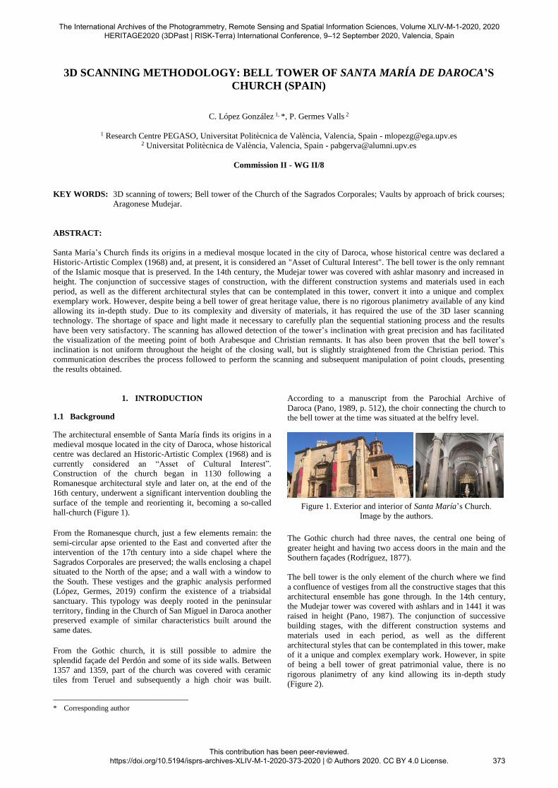
According to a manuscript from the Parochial Archive of
Daroca (Pano, 1989, p. 512), the choir connecting the church to
the bell tower at the time was situated at the belfry level.
Figure 1. Exterior and interior of Santa María’s Church.
Image by the authors.
The Gothic church had three naves, the central one being of
greater height and having two access doors in the main and the
Southern façades (Rodríguez, 1877).
The bell tower is the only element of the church where we find
a confluence of vestiges from all the constructive stages that this
architectural ensemble has gone through. In the 14th century,
the Mudejar tower was covered with ashlars and in 1441 it was
raised in height (Pano, 1987). The conjunction of successive
building stages, with the different construction systems and
materials used in each period, as well as the different
architectural styles that can be contemplated in this tower, make
of it a unique and complex exemplary work. However, in spite
of being a bell tower of great patrimonial value, there is no
rigorous planimetry of any kind allowing its in-depth study
(Figure 2).
The International Archives of the Photogrammetry, Remote Sensing and Spatial Information Sciences, Volume XLIV-M-1-2020, 2020 HERITAGE2020 (3DPast | RISK-Terra) International Conference, 9–12 September 2020, Valencia, Spain
This contribution has been peer-reviewed. https://doi.org/10.5194/isprs-archives-XLIV-M-1-2020-373-2020 | © Authors 2020. CC BY 4.0 License.
373
1.2 Objectives
The research work carried out has been aimed at the
constructive and morphological analysis of the bell tower of
Santa María de Daroca’s church with the objective of
establishing the constructive evolution and document the
current state of this unique element. This main objective can be
subdivided into three specific objectives:
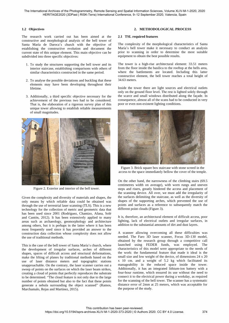
1. To study the structures supporting the bell tower and its
interior staircase, establishing comparisons with others of
similar characteristics constructed in the same period.
2. To analyse the possible deviations and buckling that these
elements may have been developing throughout their
lifetime.
3. Additionally, a third specific objective necessary for the
achievement of the previous two had to be considered.
That is, the elaboration of a rigorous survey plan of this
unique tower allowing to establish reliable measurements
of small magnitudes.
Figure 2. Exterior and interior of the bell tower.
Given the complexity and diversity of materials and shapes, the
only means by which reliable data could be obtained was
through the use of terrestrial laser scanning (TLS). This is a new
technology for the collection of metric and geometric data that
has been used since 2001 (Rodríguez, Chamizo, Afana, Solé
and Cantón, 2012). It has been extensively applied to many
areas such as archaeology, geomorphology and architecture
among others, but it is perhaps in the latter where it has been
most frequently used since it has provided an answer to the
construction data collection whose complexity does not allow
the use of traditional methods.
This is the case of the bell tower of Santa María’s church, where
the development of irregular surfaces, arches of different
shapes, spaces of difficult access and structural deformations,
make the lifting of planes by traditional methods based on the
use of laser distance meters and topographic stations
unapproachable. On the contrary, the laser scanner carries out a
sweep of points on the surfaces on which the laser beam strikes,
creating a cloud of points that perfectly reproduces the substrate
to be determined. “The cloud feature is not only due to the large
number of points obtained but also to the fact that these points
generate a nebula surrounding the object scanned” (Ramos,
Marchamalo, Rejas and Martínez, 2015).
2. METHODOLOGICAL PROCESS
2.1 TSL required features
The complexity of the morphological characteristics of Santa
María’s bell tower make it necessary to conduct an analysis
prior to scanning in order to determine the most suitable
equipment to obtain the best possible results.
The tower is a high-rise architectural element: 33.51 meters
from the floor inside the basilica to the rooftop at the bells area,
where the battlements are located. Including this latter
constructive element, the bell tower reaches a total height of
34.63 meters.
Inside the tower there are light sources and electrical outlets
only on the ground floor level. The rest is lighted solely through
the scarce and small windows distributed along the façade. In
consequence, almost all of the scans had to be conducted in very
poor or even non-existent lighting conditions.
Figure 3. Brick square box staircase with stone screed in the
access to the space immediately bellow the cover of the temple.
On the other hand, the narrowness of the climbing stairs (69.5
centimetres width on average), with worn rungs and uneven
steps and risers, greatly hindered the access and placement of
the scanning device. All over, we must add the irregularity of
the surfaces delimiting the staircase, as well as the diversity of
shapes of the supporting arches, which prevented the use of
points and surfaces as a reference to subsequently match the
different point clouds (Figure 3).
It is, therefore, an architectural element of difficult access, poor
lighting, lack of electrical outlets and irregular surfaces, in
addition to the substantial amounts of dirt and dust layers.
A scanner allowing overcoming all these difficulties was
needed. The Faro 3D laser scanner, Focus 3D-130 model,
obtained by the research group through a competitive call
launched using FEDER funds, was employed. The
characteristics of this model were appropriate to the needs of
the work: the fundamental feature that made it ideal is the
small size and low weight of the device, of dimensions 24 x 20
x 10 cm. and a weight of 5.2 kg which facilitated its
manageability in the reduced space inside the tower.
Additionally, it has an integrated lithium-ion battery with a
four-hour runtime, which ensured its use without the need to
connect it to the electrical power during a workday, as required
for the scanning of the bell tower. The scanner has a systematic
distance error of 2mm at 25 meters, which was acceptable for
the purpose of the study.
The International Archives of the Photogrammetry, Remote Sensing and Spatial Information Sciences, Volume XLIV-M-1-2020, 2020 HERITAGE2020 (3DPast | RISK-Terra) International Conference, 9–12 September 2020, Valencia, Spain
This contribution has been peer-reviewed. https://doi.org/10.5194/isprs-archives-XLIV-M-1-2020-373-2020 | © Authors 2020. CC BY 4.0 License.
374

This scanner allows scanning at a speed between 122,000 and
976,000 points per second, so the time of each scan is not high.
The scans conducted in the bell tower were carried out at a
speed of 488,000 points/sec. which translates into a duration of
approximately 8 minutes per scan. The device also includes an
integrated 70 megapixels camera with parallax-free colour
overlay so the point clouds obtained have a photographic
realism that greatly facilitates the understanding of the final
point cloud. The camera has HDR (High Dynamic Range), that
is, it sheds light over poorly lit areas so that it adds more
“dynamic range” to the photograph, increasing the number of
shades. This feature was also of relevance given the poor
lighting inside the tower.
Another remarkable advantage in this case was that the scan’s
final output format was an FLS format file, which allows
reading by all the processing software.
2.2 Prior programming of the scans
The morphology of the tower itself posed an initial problem of
wingspan due to the reduced dimensions of the space, the
irregularity of the enclosing surfaces and steps; the poor
lighting, which in many cases was non-existent; the existence of
sustaining brick arches; the diversity of constructive systems
used: multiple types of arches, vaults of different designs and
materials; and, finally, the difficult access to the tower’s rooftop
through a narrow metal spiral staircase.
Under these circumstances, it was necessary to carefully plan
the sequential stationing process, which was divided into two
phases: the first phase going from the ground floor access to the
height reached by the square box staircase, and the second one
carried out in a downward direction beginning with the cover
and belfry to reach the point of meeting with the previous phase.
This unique approach was conditioned by the area’s adverse
climate, where there are intense snowfalls and blizzards. The
device used works correctly between 5o and 40o C, not being
advisable to its use it in temperatures out of this range. Thus, it
was necessary to perform the external scanning in the morning,
during the hours when the temperature was higher to avoid
damage to the scanner. Also, the scanning of the cover was
conducted at the time of highest natural daylight intensity. To
this circumstance must be added the need to use the scanner
during this first 4 hours in this area of the tower lacking
electrical outlets.
In principle, no referential spheres were used since, from the
beginning of the project, it was assumed that the point clouds
manipulation could be done manually using any software.
However, given the narrow spiral staircase, their use was
necessary because there were no unique references such as
points, corners, edges or flat surfaces belonging to the
constructive elements of the tower itself.
Adding to the challenge was the irregularity of the step’s
horizontal surface, which complicated the accurate placing of
the scanning device. Therefore, in many cases, the low visibility
between one scan and the next forced the addition of
intermediate scans which had not been previously planned.
The final result, therefore, was the completion of 27 internal and
13 external scans.
2.3 Scans’ processing
To carry out the processing of the scans and to be able to
transform them into a single file that could be easily handled,
we used the FARO SCENE software. For the registration of
point clouds, the automatic system used by this program was
initially employed, looking for similarities between planes and
points among the different scans in order to match them. The
automatic registration worked without errors on the outside
scans of the tower by having enough references, both of points
and of flat surfaces and also by having performed the scans with
plenty of light. However, with the tower’s internal scans we
faced two problems: in some instances, the software did not find
references that would allow the matching and in others it used
the wrong reference generating an erroneous set. In the face of
these problems, it was decided to carry out the registration
manually. Inside the tower, existing nails or stains on the brick
of the walls were used as references. No targets were used due
to the impossibility of adhering them to the walls due to the
large amount of dust accumulated. To facilitate the search of the
planes and points, it was decided to use black and white scans,
marking only the points. In this way, it was achieved that the
poor interior lighting did not affect the results (Figure 4).
The registration was done in two stages: the first one
corresponding to the first group of scans (square box staircase)
and the second one corresponding to that made from the top of
the tower to meet the last scan of the previous group. The first
stage’s registration was complex due to the difficulty that the
Scene software poses when recognizing points over irregular
and dirty surfaces. The second stage’s registration was easier
due to the planned strategic location of spheres as reference
points. Therefore, obtaining the final point cloud was a very
laborious process where many of the erroneous solutions that
the program facilitated had to be dismissed. The completion of
27 scans inside the tower greatly lengthened the process.
Figure 4. Manual registration by the Scene software.
Once a registration of the tower was obtained, it was joined to
the rest of the basilica, allowing the tower to be perfectly
located in relation to the temple without error. This action was
performed exactly in the same manner both with the exterior of
the tower and the exterior of the basilica.
Once all the registration groups were joined together, the resulting
cloud was coloured, linking the result to the images made by the
scanner. In this way, the coloured point cloud was obtained.
Finally, in order to obtain a single file, the registrations were
verified and the bonding and cleaning up process took place.
The Scene software itself performs automatic colour
adjustments and stabilizes the different registrations by
generating the point cloud that is subsequently exported to other
programs to be used in a .dwg file format.
The International Archives of the Photogrammetry, Remote Sensing and Spatial Information Sciences, Volume XLIV-M-1-2020, 2020 HERITAGE2020 (3DPast | RISK-Terra) International Conference, 9–12 September 2020, Valencia, Spain
This contribution has been peer-reviewed. https://doi.org/10.5194/isprs-archives-XLIV-M-1-2020-373-2020 | © Authors 2020. CC BY 4.0 License.
375
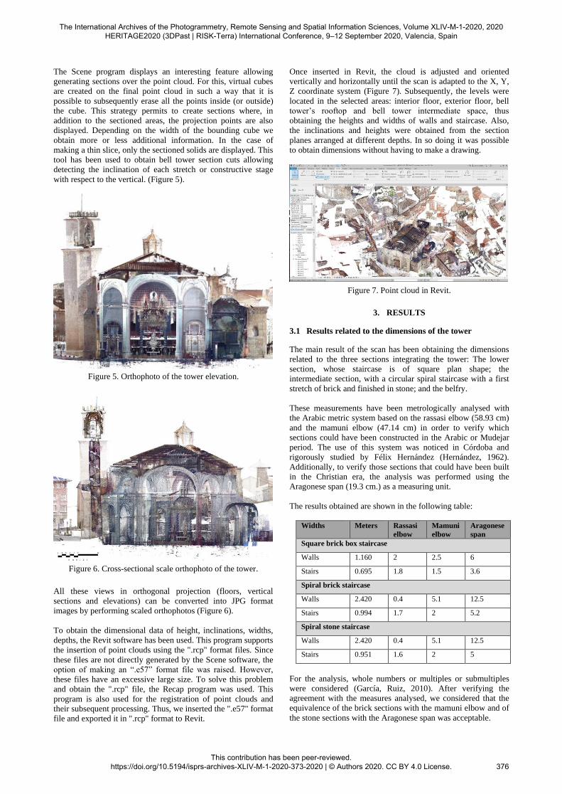
The Scene program displays an interesting feature allowing
generating sections over the point cloud. For this, virtual cubes
are created on the final point cloud in such a way that it is
possible to subsequently erase all the points inside (or outside)
the cube. This strategy permits to create sections where, in
addition to the sectioned areas, the projection points are also
displayed. Depending on the width of the bounding cube we
obtain more or less additional information. In the case of
making a thin slice, only the sectioned solids are displayed. This
tool has been used to obtain bell tower section cuts allowing
detecting the inclination of each stretch or constructive stage
with respect to the vertical. (Figure 5).
Figure 5. Orthophoto of the tower elevation.
Figure 6. Cross-sectional scale orthophoto of the tower.
All these views in orthogonal projection (floors, vertical
sections and elevations) can be converted into JPG format
images by performing scaled orthophotos (Figure 6).
To obtain the dimensional data of height, inclinations, widths,
depths, the Revit software has been used. This program supports
the insertion of point clouds using the ".rcp" format files. Since
these files are not directly generated by the Scene software, the
option of making an “.e57” format file was raised. However,
these files have an excessive large size. To solve this problem
and obtain the ".rcp" file, the Recap program was used. This
program is also used for the registration of point clouds and
their subsequent processing. Thus, we inserted the ".e57" format
file and exported it in ".rcp" format to Revit.
Once inserted in Revit, the cloud is adjusted and oriented
vertically and horizontally until the scan is adapted to the X, Y,
Z coordinate system (Figure 7). Subsequently, the levels were
located in the selected areas: interior floor, exterior floor, bell
tower’s rooftop and bell tower intermediate space, thus
obtaining the heights and widths of walls and staircase. Also,
the inclinations and heights were obtained from the section
planes arranged at different depths. In so doing it was possible
to obtain dimensions without having to make a drawing.
Figure 7. Point cloud in Revit.
3. RESULTS
3.1 Results related to the dimensions of the tower
The main result of the scan has been obtaining the dimensions
related to the three sections integrating the tower: The lower
section, whose staircase is of square plan shape; the
intermediate section, with a circular spiral staircase with a first
stretch of brick and finished in stone; and the belfry.
These measurements have been metrologically analysed with
the Arabic metric system based on the rassasi elbow (58.93 cm)
and the mamuni elbow (47.14 cm) in order to verify which
sections could have been constructed in the Arabic or Mudejar
period. The use of this system was noticed in Córdoba and
rigorously studied by Félix Hernández (Hernández, 1962).
Additionally, to verify those sections that could have been built
in the Christian era, the analysis was performed using the
Aragonese span (19.3 cm.) as a measuring unit.
The results obtained are shown in the following table:
Widths Meters Rassasi
elbow
Mamuni
elbow
Aragonese
span
Square brick box staircase
Walls 1.160 2 2.5 6
Stairs 0.695 1.8 1.5 3.6
Spiral brick staircase
Walls 2.420 0.4 5.1 12.5
Stairs 0.994 1.7 2 5.2
Spiral stone staircase
Walls 2.420 0.4 5.1 12.5
Stairs 0.951 1.6 2 5
For the analysis, whole numbers or multiples or submultiples
were considered (García, Ruiz, 2010). After verifying the
agreement with the measures analysed, we considered that the
equivalence of the brick sections with the mamuni elbow and of
the stone sections with the Aragonese span was acceptable.
The International Archives of the Photogrammetry, Remote Sensing and Spatial Information Sciences, Volume XLIV-M-1-2020, 2020 HERITAGE2020 (3DPast | RISK-Terra) International Conference, 9–12 September 2020, Valencia, Spain
This contribution has been peer-reviewed. https://doi.org/10.5194/isprs-archives-XLIV-M-1-2020-373-2020 | © Authors 2020. CC BY 4.0 License.
376
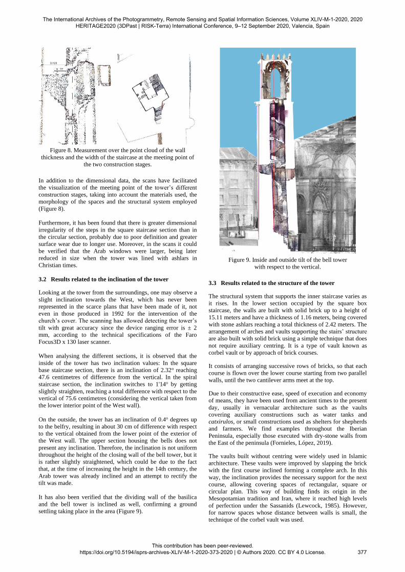
Figure 8. Measurement over the point cloud of the wall
thickness and the width of the staircase at the meeting point of
the two construction stages.
In addition to the dimensional data, the scans have facilitated
the visualization of the meeting point of the tower’s different
construction stages, taking into account the materials used, the
morphology of the spaces and the structural system employed
(Figure 8).
Furthermore, it has been found that there is greater dimensional
irregularity of the steps in the square staircase section than in
the circular section, probably due to poor definition and greater
surface wear due to longer use. Moreover, in the scans it could
be verified that the Arab windows were larger, being later
reduced in size when the tower was lined with ashlars in
Christian times.
3.2 Results related to the inclination of the tower
Looking at the tower from the surroundings, one may observe a
slight inclination towards the West, which has never been
represented in the scarce plans that have been made of it, not
even in those produced in 1992 for the intervention of the
church’s cover. The scanning has allowed detecting the tower’s
tilt with great accuracy since the device ranging error is ± 2
mm, according to the technical specifications of the Faro
Focus3D x 130 laser scanner.
When analysing the different sections, it is observed that the
inside of the tower has two inclination values: In the square
base staircase section, there is an inclination of 2.32o reaching
47.6 centimetres of difference from the vertical. In the spiral
staircase section, the inclination switches to 1'14o by getting
slightly straighten, reaching a total difference with respect to the
vertical of 75.6 centimetres (considering the vertical taken from
the lower interior point of the West wall).
On the outside, the tower has an inclination of 0.4o degrees up
to the belfry, resulting in about 30 cm of difference with respect
to the vertical obtained from the lower point of the exterior of
the West wall. The upper section housing the bells does not
present any inclination. Therefore, the inclination is not uniform
throughout the height of the closing wall of the bell tower, but it
is rather slightly straightened, which could be due to the fact
that, at the time of increasing the height in the 14th century, the
Arab tower was already inclined and an attempt to rectify the
tilt was made.
It has also been verified that the dividing wall of the basilica
and the bell tower is inclined as well, confirming a ground
settling taking place in the area (Figure 9).
Figure 9. Inside and outside tilt of the bell tower
with respect to the vertical.
3.3 Results related to the structure of the tower
The structural system that supports the inner staircase varies as
it rises. In the lower section occupied by the square box
staircase, the walls are built with solid brick up to a height of
15.11 meters and have a thickness of 1.16 meters, being covered
with stone ashlars reaching a total thickness of 2.42 meters. The
arrangement of arches and vaults supporting the stairs’ structure
are also built with solid brick using a simple technique that does
not require auxiliary centring. It is a type of vault known as
corbel vault or by approach of brick courses.
It consists of arranging successive rows of bricks, so that each
course is flown over the lower course starting from two parallel
walls, until the two cantilever arms meet at the top.
Due to their constructive ease, speed of execution and economy
of means, they have been used from ancient times to the present
day, usually in vernacular architecture such as the vaults
covering auxiliary constructions such as water tanks and
catxirulos, or small constructions used as shelters for shepherds
and farmers. We find examples throughout the Iberian
Peninsula, especially those executed with dry-stone walls from
the East of the peninsula (Fornieles, López, 2019).
The vaults built without centring were widely used in Islamic
architecture. These vaults were improved by slapping the brick
with the first course inclined forming a complete arch. In this
way, the inclination provides the necessary support for the next
course, allowing covering spaces of rectangular, square or
circular plan. This way of building finds its origin in the
Mesopotamian tradition and Iran, where it reached high levels
of perfection under the Sassanids (Lewcock, 1985). However,
for narrow spaces whose distance between walls is small, the
technique of the corbel vault was used.
The International Archives of the Photogrammetry, Remote Sensing and Spatial Information Sciences, Volume XLIV-M-1-2020, 2020 HERITAGE2020 (3DPast | RISK-Terra) International Conference, 9–12 September 2020, Valencia, Spain
This contribution has been peer-reviewed. https://doi.org/10.5194/isprs-archives-XLIV-M-1-2020-373-2020 | © Authors 2020. CC BY 4.0 License.
377
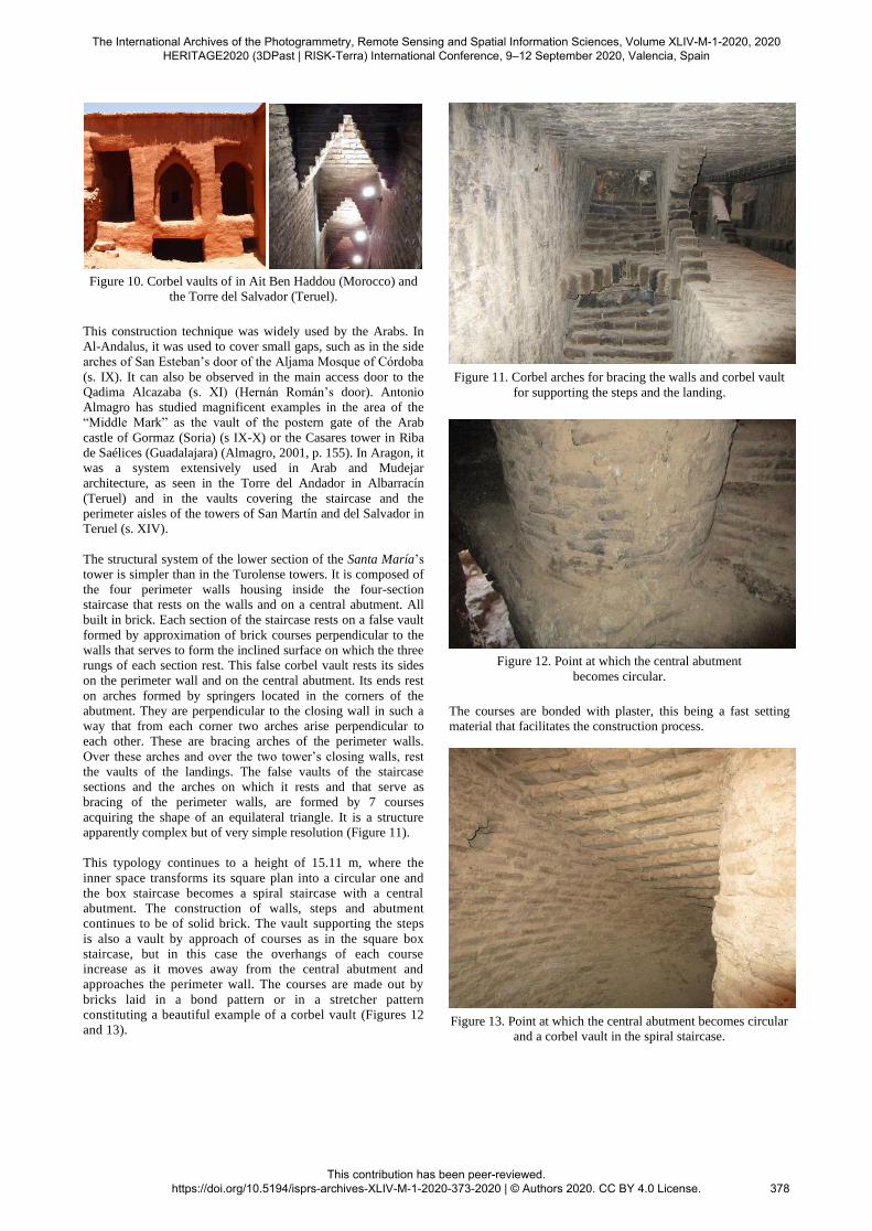
Figure 10. Corbel vaults of in Ait Ben Haddou (Morocco) and
the Torre del Salvador (Teruel).
This construction technique was widely used by the Arabs. In
Al-Andalus, it was used to cover small gaps, such as in the side
arches of San Esteban’s door of the Aljama Mosque of Córdoba
(s. IX). It can also be observed in the main access door to the
Qadima Alcazaba (s. XI) (Hernán Román’s door). Antonio
Almagro has studied magnificent examples in the area of the
“Middle Mark” as the vault of the postern gate of the Arab
castle of Gormaz (Soria) (s IX-X) or the Casares tower in Riba
de Saélices (Guadalajara) (Almagro, 2001, p. 155). In Aragon, it
was a system extensively used in Arab and Mudejar
architecture, as seen in the Torre del Andador in Albarracín
(Teruel) and in the vaults covering the staircase and the
perimeter aisles of the towers of San Martín and del Salvador in
Teruel (s. XIV).
The structural system of the lower section of the Santa María’s
tower is simpler than in the Turolense towers. It is composed of
the four perimeter walls housing inside the four-section
staircase that rests on the walls and on a central abutment. All
built in brick. Each section of the staircase rests on a false vault
formed by approximation of brick courses perpendicular to the
walls that serves to form the inclined surface on which the three
rungs of each section rest. This false corbel vault rests its sides
on the perimeter wall and on the central abutment. Its ends rest
on arches formed by springers located in the corners of the
abutment. They are perpendicular to the closing wall in such a
way that from each corner two arches arise perpendicular to
each other. These are bracing arches of the perimeter walls.
Over these arches and over the two tower’s closing walls, rest
the vaults of the landings. The false vaults of the staircase
sections and the arches on which it rests and that serve as
bracing of the perimeter walls, are formed by 7 courses
acquiring the shape of an equilateral triangle. It is a structure
apparently complex but of very simple resolution (Figure 11).
This typology continues to a height of 15.11 m, where the
inner space transforms its square plan into a circular one and
the box staircase becomes a spiral staircase with a central
abutment. The construction of walls, steps and abutment
continues to be of solid brick. The vault supporting the steps
is also a vault by approach of courses as in the square box
staircase, but in this case the overhangs of each course
increase as it moves away from the central abutment and
approaches the perimeter wall. The courses are made out by
bricks laid in a bond pattern or in a stretcher pattern
constituting a beautiful example of a corbel vault (Figures 12
and 13).
Figure 11. Corbel arches for bracing the walls and corbel vault
for supporting the steps and the landing.
Figure 12. Point at which the central abutment
becomes circular.
The courses are bonded with plaster, this being a fast setting
material that facilitates the construction process.
Figure 13. Point at which the central abutment becomes circular
and a corbel vault in the spiral staircase.
The International Archives of the Photogrammetry, Remote Sensing and Spatial Information Sciences, Volume XLIV-M-1-2020, 2020 HERITAGE2020 (3DPast | RISK-Terra) International Conference, 9–12 September 2020, Valencia, Spain
This contribution has been peer-reviewed. https://doi.org/10.5194/isprs-archives-XLIV-M-1-2020-373-2020 | © Authors 2020. CC BY 4.0 License.
378

4. CONCLUSIONS
The 3D scanning-based methodology used has allowed a
rigorous survey of a complex bell tower that would have not
been possible to achieve by other means or techniques.
Likewise, it has been possible to accurately measure the
deformations suffered over time, verifying that the deviations
differ in each construction stage.
Additionally, we have been able to precisely determine the
constructive evolution from its Arab origin to the present day
through the rigorous and precise measurement taken by means
of the point cloud and its implementation in Revit, verifying
that the dimensions of the lower section of the tower fit the
mamuni elbow and the upper section, built in stone, fit the
Aragonese span. Likewise, the thicknesses of the walls and the
heights of the different construction stages have been measured,
verifying that the first one is 15.11 m. high, that is, 32 exact
elbows, which leads one to think that this part belonged to the
ancient Islamic mosque’s minaret on which the church sits.
Similarly, the thickness of slabs and vaults of the staircase has
been accurately measured, corroborating that in the lower
section built in brick they are thinner and uneven, while in the
Christian section they are greater and uniform.
ACKNOWLEDGEMENTS
We thank Mr. Sergio Pérez, priest of the Church of Santa María
and the Religiosas Auxiliadoras de Cristo Sacerdote for the
facilities provided to access the temple and the bell tower. We
also thank Mr. Pascual Sánchez Domingo, responsible for the
archive, for his full disposition and assistance in the search for
documentation.
REFERENCES
Almagro Gorbea, A., 2001: Un aspecto constructivo de las
bóvedas en al-Andalus. Al-Qantara revista de estudios árabes
XXII (1) 147-170
García Ortega, A.J., Ruiz de la Rosa, J.A., 2010: Diseño
estructural en el primer gótico andaluz (II) Maestros y medidas.
Ega Revista de Expresión Gráfica en la Arquitectura 15, 46-53
Hernández, F., 1962: El codo en la historia árabe de la mezquita
mayor de Córdoba. Contribución al estudio del monumento. Al-
Mulk Anuario de estudios arabistas 2, 44-52
Lewcock, R., 1985: Materiales y técnicas. In La arquitectura
del mundo islámico. Alianza editorial, Madrid. 129-142
López González, C., Germes Valls, P., 2019: Projective analysis
of the church of Santa María de Daroca. The architecture speaks
through the drawing. In Reflections the art of drawing/The
drawing of art. Gaugeni Editore, Roma 1655-1662
Fornieles López, J., López González, C., 2019: Analysis
construction of vaults with dry stone. In Research in building
engineering Universitat Politècnica de València, 244-253
Ramos, L., Marchamalo, M., Rejas, J.G., Martínez, R., 2015:
Aplicación del láser escáner terrestre (TSL) a la modelización
de las estructuras: precisión, exactitud y diseño de la
adquisición de datos en casos reales. Informes de la
construcción 67 (538): e074, doi: dx.doi.org/10.3989/ic.13.103
Pano Gracia, J. L., 1987: Sobre la fábrica y capitulación de la
iglesia colegial de Daroca. Artigrama 4, 91-114
Pano Gracia J.L., 1989: La portada del Perdón de la iglesia
Colegial de Daroca: estado de la cuestión. Aragón en la Edad
Media, VIII. Homenaje al Profesor Emérito Antonio Ubieto
Arteta, 511-521.
Rodriguez-Caballero, E., Chamizo, S., Afana, A., Solé-Benet,
A., Cantón, Y., 2012: Automatic digital terrain model extraction
from terrestrial laser scanner data (Espada). In Avances de la
Geomorfología en España. Universidad de Cantabria. 263-266
Rodríguez y Martel, J. A., 1877: Antigüedad célebre de la santa
iglesia colegial de Santa María la Mayor de Daroca..., año
1675, Imprenta de T. Fortanet, Madrid, 242-248
The International Archives of the Photogrammetry, Remote Sensing and Spatial Information Sciences, Volume XLIV-M-1-2020, 2020 HERITAGE2020 (3DPast | RISK-Terra) International Conference, 9–12 September 2020, Valencia, Spain
This contribution has been peer-reviewed. https://doi.org/10.5194/isprs-archives-XLIV-M-1-2020-373-2020 | © Authors 2020. CC BY 4.0 License.
379