3d printing for aerospace applications
TRANSCRIPT
Printing for Aerospace ApplicationsInside 3D PrintingApril 12, 2016
Mark Walluk
Staff Engineer
Introduction
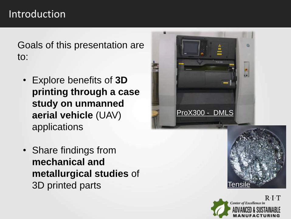
Goals of this presentation are
to:
• Explore benefits of 3D
printing through a case
study on unmanned
aerial vehicle (UAV)
applications
• Share findings from
mechanical and
metallurgical studies of
3D printed parts
ProX300 - DMLS
Tensile

Introduction
Summary
3D Design
Considerations
Material
Properties and
End Results
Intro
Introduction
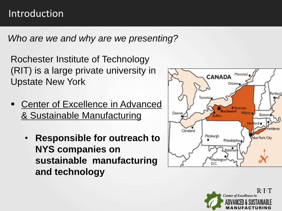
Who are we and why are we presenting?
Rochester Institute of Technology
(RIT) is a large private university in
Upstate New York
Center of Excellence in Advanced
& Sustainable Manufacturing
• Responsible for outreach to
NYS companies on
sustainable manufacturing
and technology

COE-ASM: What do we do?
COE-ASM is dedicated to helping existing and emerging manufacturing companies bridge the gap between R&D and manufacturing implementation:
• Applied Research & Development
• Technology Validation and Deployment
• Product and Process Efficiency
• Workforce development

About COE-ASM
• Multi-disciplinary academic and applied research unit at RIT
• 118 staff engineers, technicians, faculty researchers, and funded students
• 225,000 sq ft of advanced manufacturing facilities and infrastructure, with 400-seat training facility
• $70M+ in manufacturing, equipment, labs & testbeds
We are able to assist through

Design
· Mechanical and electrical design and simulation
· Design for manufacturing
· Material selection/substitution
Prototype Fabrication
· Additive manufacturing in plastic and metal
· CNC fabrication equipment
· Electrical and mechanical testing and integration
· Linkage to industry (prototype and production)
Inspection & Validation
· 3D imaging and dimensional verification
· Material characterization & properties
· Performance and robustness evaluation
Digital Manufacturing & Product Realization Lab
One lab relevant to this presentation
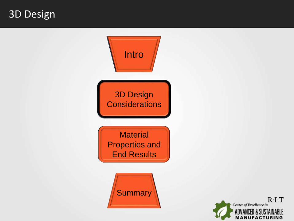
3D Design
Summary
3D Design
Considerations
Material
Properties and
End Results
Intro
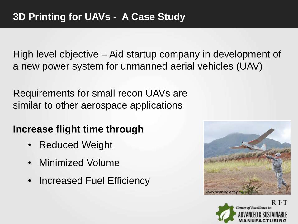
3D Printing for UAVs - A Case Study
High level objective – Aid startup company in development of
a new power system for unmanned aerial vehicles (UAV)
Requirements for small recon UAVs are
similar to other aerospace applications
Increase flight time through
• Reduced Weight
• Minimized Volume
• Increased Fuel Efficiencywww.benning.army.mil
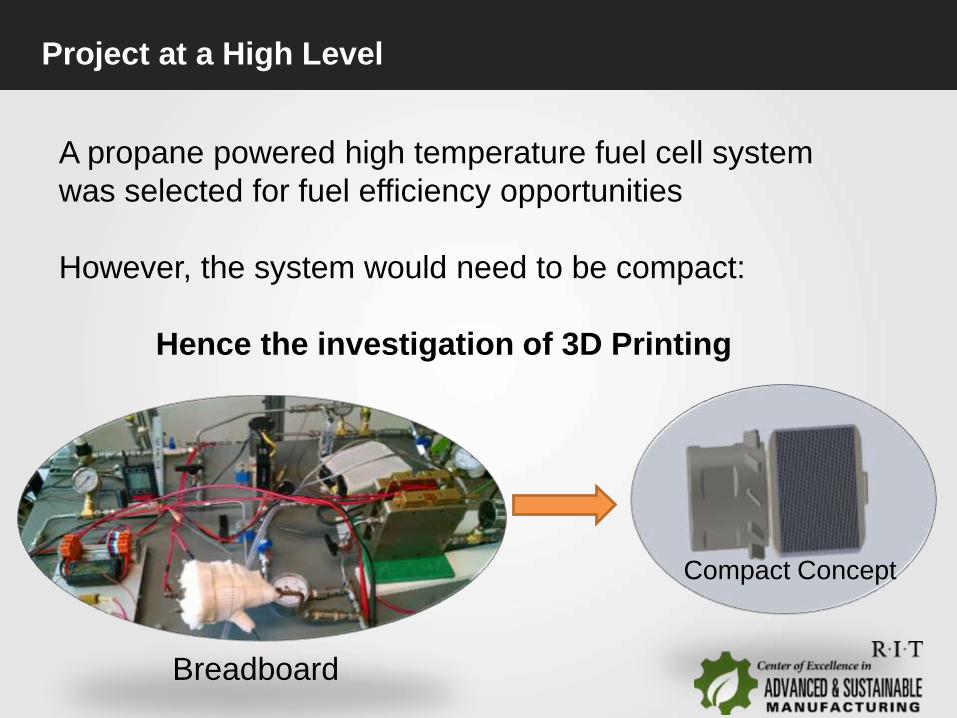
Project at a High Level
A propane powered high temperature fuel cell system
was selected for fuel efficiency opportunities
However, the system would need to be compact:
Hence the investigation of 3D Printing
Breadboard
Compact Concept
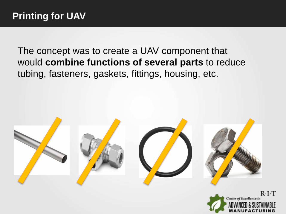
Printing for UAV
The concept was to create a UAV component that
would combine functions of several parts to reduce
tubing, fasteners, gaskets, fittings, housing, etc.

Analysis
Finite element simulations were
performed; however questions arose on
design and properties:
• How do we design for metal 3D
Printing of fuel cell parts?
• What are the mechanical
properties of printed parts?
• Does print orientation and
pattern matter?
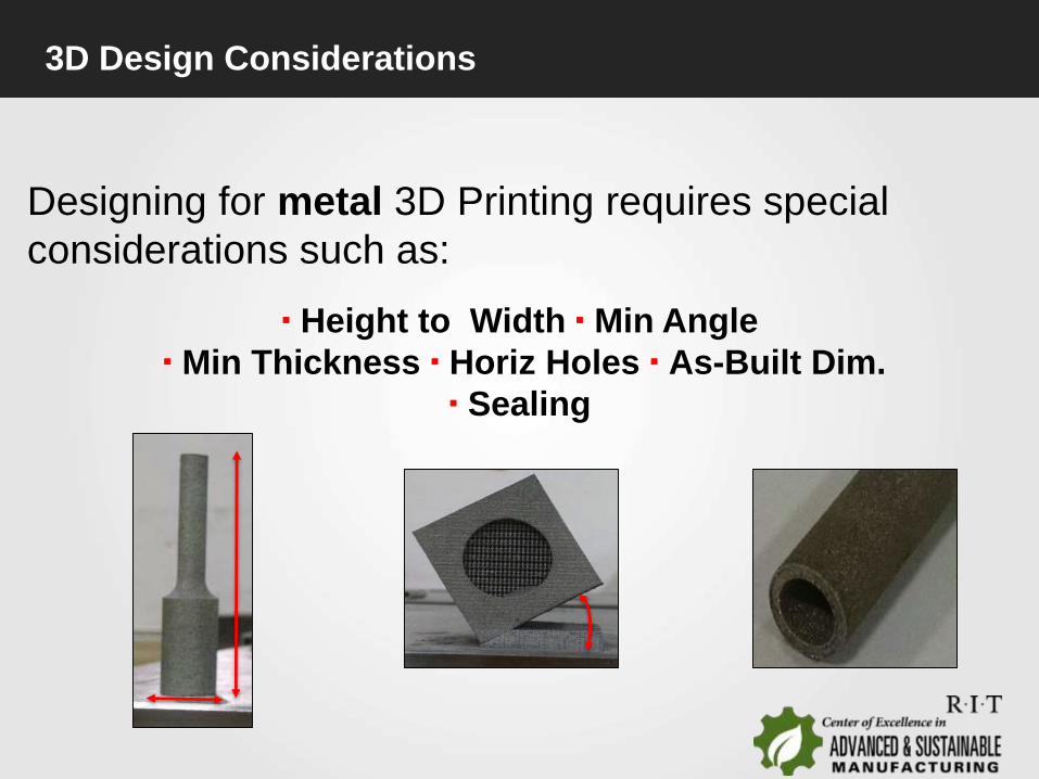
3D Design Considerations
Designing for metal 3D Printing requires special
considerations such as:
▪ Height to Width ▪ Min Angle
▪ Min Thickness ▪ Horiz Holes ▪ As-Built Dim.
▪ Sealing
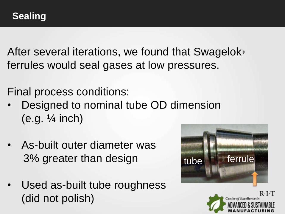
Sealing
After several iterations, we found that Swagelok®
ferrules would seal gases at low pressures.
Final process conditions:
• Designed to nominal tube OD dimension
(e.g. ¼ inch)
• As-built outer diameter was
3% greater than design
• Used as-built tube roughness
(did not polish)
tube ferrule

Guidance
Our design guidance for assurance of
high quality metal parts:
50⁰ Minimum 4:1 Max Height to Width
Wall thickness of 0.06 inch for gas sealing
Water drop shape for near horizontal holes
(> ¼ inch)
Use as-built for ferrule seals

Imperfections
The final specimens had
printing imperfections
(700µm deep) along the +Z
direction normal to the print
plane
3D-Microscopy

Fine Features
One benefit of 3D Printing is the ability to create
fine features within the component.
Multiple internal Small holes,
0.020 inch diameter, were
created without the need for
machining
Summary
3D Design
Considerations
Material
Properties and
End Results
Intro

Material Properties
The direction and pattern type
of printing was studied for
effect on mechanical
properties
• Hex vs Normal
• Angle vs roll direction
HEX Pattern
15⁰ 45⁰
Note: default build
parameters, not optimized: 400W, 40μm
R
O
L
L
E
R
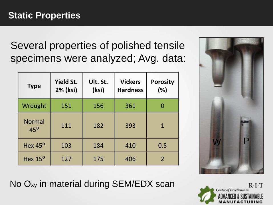
Static Properties
Several properties of polished tensile
specimens were analyzed; Avg. data:
TypeYield St. 2% (ksi)
Ult. St. (ksi)
Vickers Hardness
Porosity (%)
Wrought 151 156 361 0
Normal 45⁰
111 182 393 1
Hex 45⁰ 103 184 410 0.5
Hex 15⁰ 127 175 406 2
No Oxy in material during SEM/EDX scan
W P
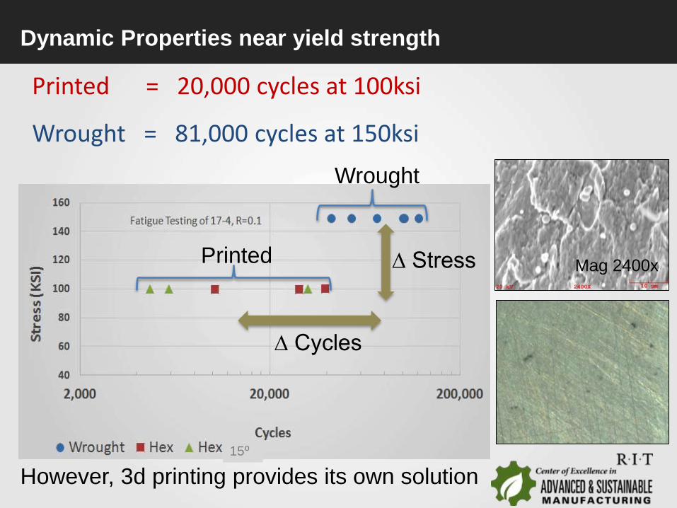
Dynamic Properties near yield strength
Printed = 20,000 cycles at 100ksi
Wrought = 81,000 cycles at 150ksi
∆ Cycles
∆ Stress Mag 2400x
15⁰
Printed
Wrought
However, 3d printing provides its own solution

Research Opportunities
Opportunities for Improvement:
• Investigate machine parameters
(e.g. layer, powder size, laser
power)
•Post Processes
•Heat treat
•Hot Isostatic Pressing
•Ultra-sonic surf. Mod.?
•Shot peen?
•Etc?
Yadollahi, et. al.; “Fatigue Behavior of Selective laser
melted 17-4PH Stainless Steel”

Summary
3D Design
Considerations
Material
Properties and
End Results
Intro
Summary
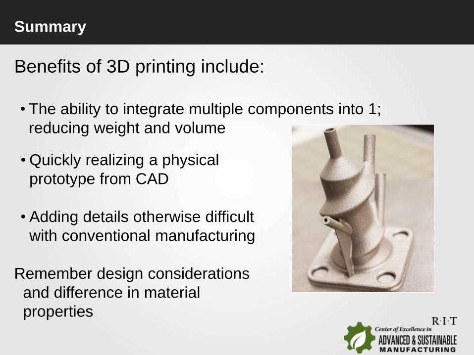
Benefits of 3D printing include:
• The ability to integrate multiple components into 1;
reducing weight and volume
• Quickly realizing a physical
prototype from CAD
• Adding details otherwise difficult
with conventional manufacturing
Remember design considerations
and difference in material
properties

For more information:[email protected]
Thank you
COE - Any opinions, findings, conclusions or recommendations expressed are
those of the author(s) and do not necessarily reflect the views of the NYS
Department of Economic Development (DED), unless otherwise directed by the
DED.
www.rit.edu/gis/cesm/
