3d location of circular and spherical features by
TRANSCRIPT

Purdue UniversityPurdue e-PubsDepartment of Electrical and ComputerEngineering Technical Reports
Department of Electrical and ComputerEngineering
3-1-1989
3D Location of Circular and Spherical Features byMonocular Model-Based VisionY. C. ShiuPurdue University
Shaheen AhmedPurdue University
Follow this and additional works at: https://docs.lib.purdue.edu/ecetr
This document has been made available through Purdue e-Pubs, a service of the Purdue University Libraries. Please contact [email protected] foradditional information.
Shiu, Y. C. and Ahmed, Shaheen, "3D Location of Circular and Spherical Features by Monocular Model-Based Vision" (1989).Department of Electrical and Computer Engineering Technical Reports. Paper 650.https://docs.lib.purdue.edu/ecetr/650
!vXv.v.v.v.v.v.;.v.v.v.v.;.v.;.v.-.v.
m m M M M m m m
m m m m m m m m m m• • • • • ••••*••••••••••••«•••••••••*
VliXvl̂ iXiIvlvlvxvliXiIyxiZlvxvlvIvXvIv!;!;I;I;I|X;IvIlIlI;I;I;I;I;IlI;I;I;I;Iv!vI;>XvIvIvIvXvI;IvIvXvIvXvIvIvI;XvXvXvX;XvXvXvX'v!v!v\vX\vXvXvX\\vX;X;X;XvX;X;X;X;X;XvX;IX'*!vXvX*IvX;XyyvX;XvXiXi!vXvXvXvXv!
3D Location of Circular and Spherical Features by Monocular Model-Based Vision
Y. C. ShiuShaheen Ahmad
■ ■ ■ '! *'' ' ■ . ■ ' '
TR-EE 89-18 March, 1989
School of Electrical EngineeringPurdue UniversityWest LafayetterIndiana 47907

3D L ocation o f C ircular and Spherical F eatu res b y M onocu lar M od el-B ased V ision
Y.C.Shiu and Shaheen Ahmad
School of Electrical Engineering, Purdue University, West Lafayette, Indiana 47907
A B S T R A C T
This paper addresses the mathematics for using monocular model-based vision to find the 3-D positions of circular and spherical model features, and, for the circular case, orientations as well. Monocular model-based vision here refers to the use of a single projective image of modeled objects to solve for the 3-D positions and orientations of the objects in the scene. The mathematics for solving 3-dimensional position and orientation of the object from matched model and image points/lines features are well known. However, no known paper addresses spherical features arid very few papers address the mathematics involving circular model features. This paper describes a novel closed-formed solution for the 3-D position and orientation of a circular features and the 3-D position of a spherical feature. The number of solutions for the circular case is found to be two in general, but there is only one solution when the surface normal of the circular feature passes through the center of projection. There is only one solution for the circular case. Advantages of this method are: (1) Handles sphericalas well as circular features. (2) Closed-form solution. (3) Gives only the necessary number of solutions (no redundant solutions). (4) Simple mathematics involving 3-D analytic Geometry. (5) Geometrically intuitive.
INTRODUCTIONMonocular vision can be used to find 3-D position and orientation of an object if
the object model is known. Most of the mathematics developed for recovering the object position from a monocular image is based on point features [Fischler, Ganapathy, Haraliek a,b, Shiu, Wolf]. If the correspondence between image point features and model point features are known, viewpoint recovery mathematics can be use to find the 3-D position and orientation of the object position. In model-based monocular applications, this correspondence is not known initially. However, heuristics are used to hypothesize the correspondence between the image features and the model features. The correspondence hypothesis can be used to calculate the object position. The hypothesis is verified by projecting the model at the calculated position onto the image plane and compare it with the input image. If it closely reseriible the image, the hypothesis is taken as the result. Otherwise. further hypotheses will be generated until one is verified to be true. The mathematics* based ori line features has also been developed [Lowe] and is similar to that of using point features.
Viewpointrecbverymathematicsforpointandliriefeaturescannotbeappliedtoobjects dominated by circular and spherical features, because either there are no vertices or lines present in the image, or the vertices or lines in the image does not have corresponding vertices or lines in the 3-D object model. Example of the first case is the image of a ball; it does not have points or lines. Example of the second case is the image of a circular cylinder; it has four vertices and two straight lines but none of

them have any corresponding vertices or lines in the 3-D object model. Thus, special viewpoint recovery mathematics is needed to be developed for circular and spherical features. The availability of such mathematics allows the recognition and location of 3-D objects dominated by circular and elliptical features from a single perspective image.
There is no previous work for the viewpoint determination of spherical features that the authors know of. However, there are some previous work related to the viewpoint determination for a circular feature. Haralick et. al. [Haralick a,b] developed viewpoint determination mathematics for second-degree curves. Although their method is more general in the sense that it handles second degree curves and not just xircles, it has the drawbacks that it is iterative, that an initial estimation is required, that the number of possible solutions are not given, and that no geometric interpretation is given. It is also not clear how the iterative solutions will perform when the method tries to find all the 6 degrees of freedom of the circular feature while the circle can only be fixed to 5 degrees of freedom because of its rotational symmetry. Mulgaonkar [Mulgaonkar] gave an iterative solution to determine the viewpoint of a circular feature. Marimont [Marimont] presented a closed-form solution for the circular feature. However, his method is mathematicallymore complex than this paper’s approach. His paper is based on linear algebra rather than 3-D analytic geometry, resulting in solutions that are not geometrically intuitive. Marimont5S method gives 8 solutions: 4 of them are behind the camera and 4 of them are in front of the camera. The solutions are redundant because he stated that out of the 4 solutions in front of the camera, there are 2 distinct ones. (In fact, there may be I or 2 distinct solutions. K the surface normal of the circular feature passes through the center of projection, there is only one solution. Otherwise there are two solutions.) Lastly, Marimont’s method does not allow spherical features.
We have developed a closed-form method for viewpoint determination for not only circular features, but also for spherical features. The method is based on the formation of a second degree cone having the center of projection (camera focal point) as vertex and passing through the ellipse on the image plane. Because 3-D analytic geometry is involved, the solution is geometrically intuitive. It also uses simpler mathematics compared to Marimont’s method [Marimont] and it does not give redundant solutions.
Section 2 discusses not only why the projection of 3-D circular and spherical features onto the image plane are ellipses, it gives the mathematics to find the image ellipse given the 3-D position of a circular or spherical feature. Section 3 discusses the mathematics for viewpoint determination given the ellipse on the image plane and the radius of the model circular or spherical feature.
2 PROJECTION OF CIRCULAR AND SPHERICAL FEATURES ONTO THE IMAGE PLANE
There are two reasons to study the projection of circular and spherical features onto the image plane: (I) To understand the formation of the image ellipse. (2) 'Fo find the equation of the image ellipse for simulation needs. We will first address the case of a circular feature. Then the spherical case will be discussed.
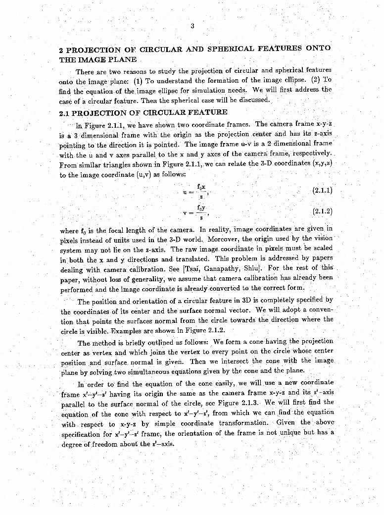
2.1 PRO JECTION OF CIRCULAR FEATUREIn Figure 2.1.1, we have shown two coordinate frames. The camera frame x-y-z
is a 3 dimensibnal frame with the origin as the projection center and has its .;z-axis pbintihg to the direction it is pointed. The image frame u-v is a 2 dimensional frame with the u and v axes parallel to the x and y axes of the camera frame, respectively. F r o m similar triangles shown in Figure 2.1.1, we can relate the 3-D coordinates (x,y,z) to the image coordinate (u,v) as follows:
Ufpx
Z
v = ^ p , '
where f0 is the focal length of the camera. In reality, image coordinates are given in pixels instead of units used in the 3-D world. Moreover, the origin used by the vision system may not lie on the z-axis. The raw image coordinate in pixels must be scaled in both the x and y directions and translated. This problem is addressed by papers dealing with camera calibration. See [Tsai, Ganapathy, Shiu]. For the rest of this paper, without loss of generality, we assume that camera calibration has already been performed and the image coordinate is already converted to the correct form.
The position and orientation of a circular feature in 3D is completely specified by the coordinates of its center and the surface normal vector. We will adopt a convention that points the surfaces normal from the circle towards the direction where thecircle is visible. Examples are shown in Figure 2.1.2.
The method is briefly outlined as follows: We form a cone having the projection center as vertex and which joins the vertex to every point on the circle whose center position and surface normal is given. Then we intersect the cone with the image plane by solving two simultaneous equations given by the cone and the plane.
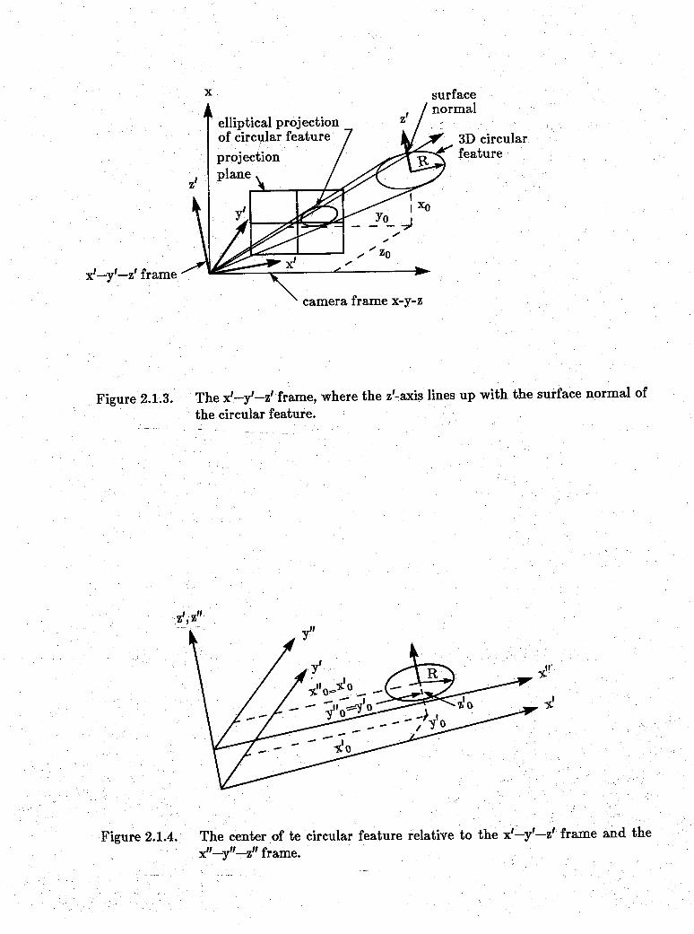
In order to find the equation of the cone easily, we will use a new coordinate frame x'—y'—z' having its origin the same as the camera frame x-y-z and its z'—axis parallel to the surface normal of the circle, see Figure 2.1.3. We will first find the equation of the cone with respect to x'-y — z', from which we can find the equation with respect to x-y-z by simple coordinate transformation. Given the above specification for x'-y'-z' frame, the orientation of the frame is not unique but has a degree of freedom about the z'—axis.
We will present a method to find an X1- J 1-Z i frame that satisfies the given constraints and which works for all possible orientation of the circular feature. Let the direction of the circular curvature be (vx,vy,vz)T. Let the following homogeneous transformation matrix represent the x'—y'—z' relative to the x-y-z frame.
nX °x aX0
aZ 0<VO O
(2.1.3)
aXay = . vyaz V2
Since (ax,ay,az)T can be interpreted as the direction of the z5-axis with respect to x-y-z frame [Paul] and since it has to be parallel to the normal vector of the circle,
(2.1.4)
The X 5 and y } axes can be arbitrarily picked as long as they are orthogonal to z’-axis and orthogonal to each other. We will select first the y ’ direction. The x'-axis can then be found by taking the cross product of the vectors representing the y \ and axes. The orthogonality constraint between the z’ and y ’ axes results in
axox+ayoy+azoz=0- (2.1.5)
From this equation, we can express (ox,oy,oz)T as a linear combination of two known vectors. For example, from Equation 2.1.5, ox = (oyay—ozaz)/ax. Thus,
; “ az ■0X aX aX
; V-r.. ■■ °y =* °y I +Oz O■ • . O2 O I
(2.1.6)
Here, we can arbitrarily choose oy and oz, and ox is fixed from the equation in terms of oy and Oz- Similarly, we can fix oy or oz, resulting in the following two equations:
(2.1.7)0 X
° y = °X“ a x
+ ° z
O
- a Z
• a y
■■■■■;' ■■■ ■ : : - "° z
O . I
a n d"■
' ' .. \ •' ■■ ■■; \ . . ' . , . ; . r .-I
■ : V ' ~ :■o x I O
■■ . ; . '■■■ ■■.; ‘ ■ ■ Oy = Ox O + ° y T
. ; . . ' - : • ' . . ■ • Oz —aX ~ a y
. aZ ;
(2. 1.8)
We will use the following rule to assign values to (ox,oy,oz) to avoid dividing by zero or
near zero.If I ax I > I ^ I > | a, | , we will use Equation 2.1.6 and set o2 to zero, resulting in
~ H
OxI '
axI°y --. •
0 Z\ / ^
0(24-9)
If I ay I > I a X I > I az I, we will use Equation 2.1.7 and set o2 to zero, resulting in. V • > Y ■ ’ I
°xI “ ax
v;:;->Y - V^Y ^ Y - . . : °yH
Oz\ / > V 0
(2.1.10)
If I az I > I ax I > I ay | , we will use Equation 2.1.8 and set oy to zero, resulting in
; ■■ . . OxI ■
IG■ \ • . °y
■Y.. ; :. • °z \ / i + 4“ ax
Y-Y' Y V V aZ
(2.1.11)
To find (nx,ny,nz), we take a cross product of the y ’ and z’ axis, resulting in:
11X Oya2-EyO2
ny = aX0Z-0XaZ ̂ : v: ; ; ■■ . nz Oxay— ExOy
(2.1.12)
Now we will find the equation of the cone based on x'~y'—z' axis: We must first find the new coordinate of the circle center. If the circle center is (x0,y0,z0)T relative to x-y-z, theii its position (x'0,y'0,z'0)T relative to x'-y'-ztis
(2.143)
The geometry of the problem is shown in Figure 2.1.4. Since the z' axis is parallel to the normal ^vector of the circle, the plane of the circle must Jbe parallel to the 3c'—y' plane. Let us set up a new coordinate frame x"—y"—z" having the same orientation as x'—y'—z' but whose original is at (0,0,z'0) relative to x'—y'—z'. This frame of reference is shown in Figure 2.1.4. The equation of the circle with respect to x',-y"-z" is
■" (x"-x'0)2+(y"-y'0)2=R2- (2-1.14)
x O X0-
n xx O + n y y o + n zz O
. . y 'o — T -1 yo = OxXo+Oj-yo+OzZo
z O Zo a x X o + E y y o + a zZo

The desired cone consists of infinite number of lines each pass through a point on the circle. The two point form of a line passing through the origin and a point (x",y V 0) on the circle has the formula
(2.1.15)x"—0 yH—0 Zf0-O
from which we have
x" =z'rix' z'0y'
and y" (2.1.16)
V X nxx+nyy+nzz
y' _ ^ p -I y oxx+oyy+ozzy . Z axx+ayy+azz
Substituting Equation 2.1.16 into Equation 2.1.14 and grouping the x'2, y'2, z'2, xy, yz, xz terms, we have
z'o2x'2+z'o2y'2+(x'o2+y'o2)*'2-2x '0z'0x'z'-2y'0z'0y'z' = 0. (2.1..17)
This is an equation of the cone specified according to the xl—y'—z1 coordinate frame. The lack of a constant term indicates that the cone passes through the origin. Next we need to find the equation of the same cone with respect to the x-y-z frame. This is achieved by the following substitution into Equation 2.1.17,
(2.1.18)
resulting in a second order equation in terms of x, y, and z. To find the equation of ellipse projected on the image plane (z — f0), we intersect the cone equation with the projection plane z=f0, which is equivalent to setting z to f0 in the cone equation. The resulting second degree equation is obtained by the aid of SMP .[SMPj.: . ; ■
ax2-f-by2+cxy+dx+ey+f = 0, (2.1.19)
where
a =■— ax2R2+ Ex2X02+ ax2yQ2+ n x2Zo2+ o x2Zo2—2axilxXQZq—2axoxyoZo,
: b = —ay2R2H-ay2Xo2+ay2Xo24-ny2Zo2+Oy2ZQ2—2ayiiyXoZo—2ayOyyoZo
C = 2(—axayR2+axayXo2+axayyo2+oxoyz02—axnyx0Zo—ax6yy0z0—EyIixXoZ0- ayOxy 0z0) —
d = 2f0(—axazR2+axazx02+axazy02+nxnzz02+oxozz02—axnzx0z0—axozy0z0—aznxx0Zo—a2oxy0z0)
e = 2fo(-ayazR2+ ayazx02+ ayazyo2+ n ynzz02+ oyozZo2- a ynzXoZ0- a yozyoZo-aznyx0Zo-azoyyoZo)
:f =: f02(—az?R24-az2xQ2-faz2yQ2+nz2zQ2+oz2z02—2aznzx0z0—2azozy0z0)
2,2 PROJECTION OF SPHERICAL FEATURE
In the spherical case, we also have to find the equation of the cone and then intersect it to the image plane. In this case, the cone is always a right circular cone
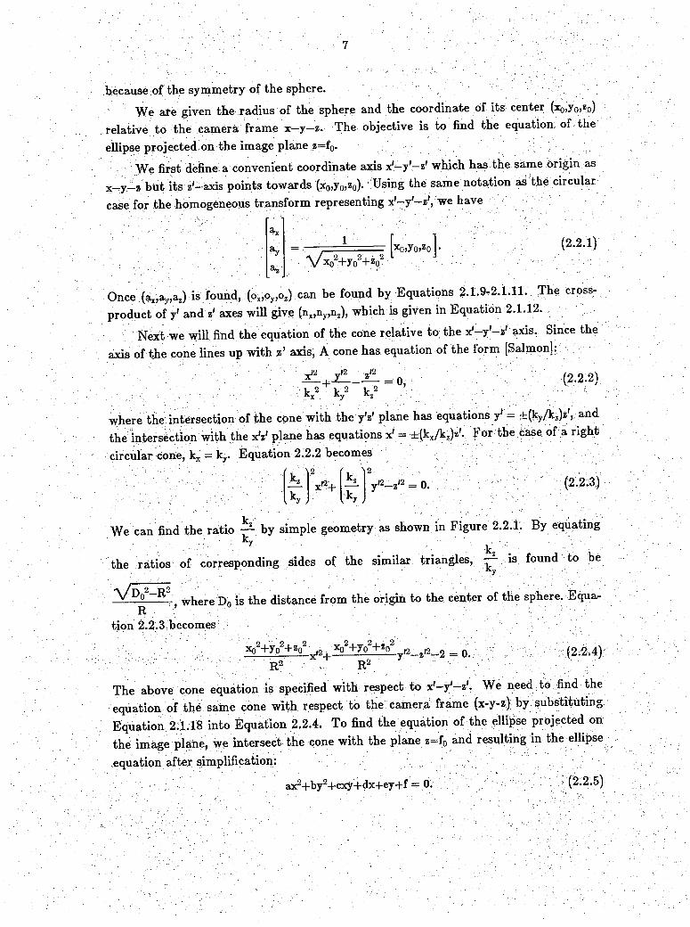
because of the symmetry of the sphere.We are given the radius of the sphere and the coordinate of its center (x0,y0,z0)
relative to the camera frame x—y—z. The objective is to find the equation of the ellipse projected on the image plane z=f0.
We first define a convenient coordinate axis x'-y'-z' which has the same Origin as x_y_z but its z-axis points towards (x0,y0,z0). Using the same notation as the circular case for the homogeneous transform representing x'-y'-z', we have
' V x o 2-Hy o2+ z o2xo>yo>zo]•
(2.2. 1)
Once (ax,ayja,) is found, (ox,oy,oz) can be found by Equations 2.1.9-2.1.11. The cross- product of y' and z' axes will give (nx,ny,nz), which is given in Equation 2.1.12.
Next we will find the equation of the cone relative to the x'-y'-z' axis. Since the axis of the cone lines up with z’ axis, A cone has equation of the form [Salmon]:
* ! 1 + ^ - 4 = o, : (2-2-2)V 2 V 2 V2. - - K x- Ky K z.
w ;h e r e the intersection of the cone with the y'z' plane has equations y' = ±(ky/kz)z', and the intersection with the xV plane has equations x' = ±(kx/kz)z'. For the case of a right circular cone, kx = ky. Equation 2.2.2 becomes
x'2+ — y'2—z'2 = 0. (2.2.3)Yk ^2
*n )
We can find the ratio — by simple geometry as shown in Figure 2.2.1. By equalingv: . -Jv'. k -
the ratios of corresponding sides of the similar triangles, - 1 is found to be
^ D° R2 where Dn is the distance from the origin to the center of the sphere. Equa-R ’ - ; ■ .. N- /.-,■■■
tion 2.2.3 becomes
Xo2Fyo2-Hz02 ^ - V j T g W y(2,_ ^ _ 9 _ n ;R 2 ' R2
(2.2.4)
The above cone equation is specified with respect to x'-y'-z'. We need to find the equation of the same cone with respect to the camera frame (x-y-z) by substituting Equation 2.1.18 into Equation 2,2.4. To find the equation of the ellipse projected on the image plane, we intersect the cone with the plane z=f0 and resulting in the ellipse equation after simplification:
ax2+by2+cxy+dx-t-ey+f = 0. (2.2.5)
where
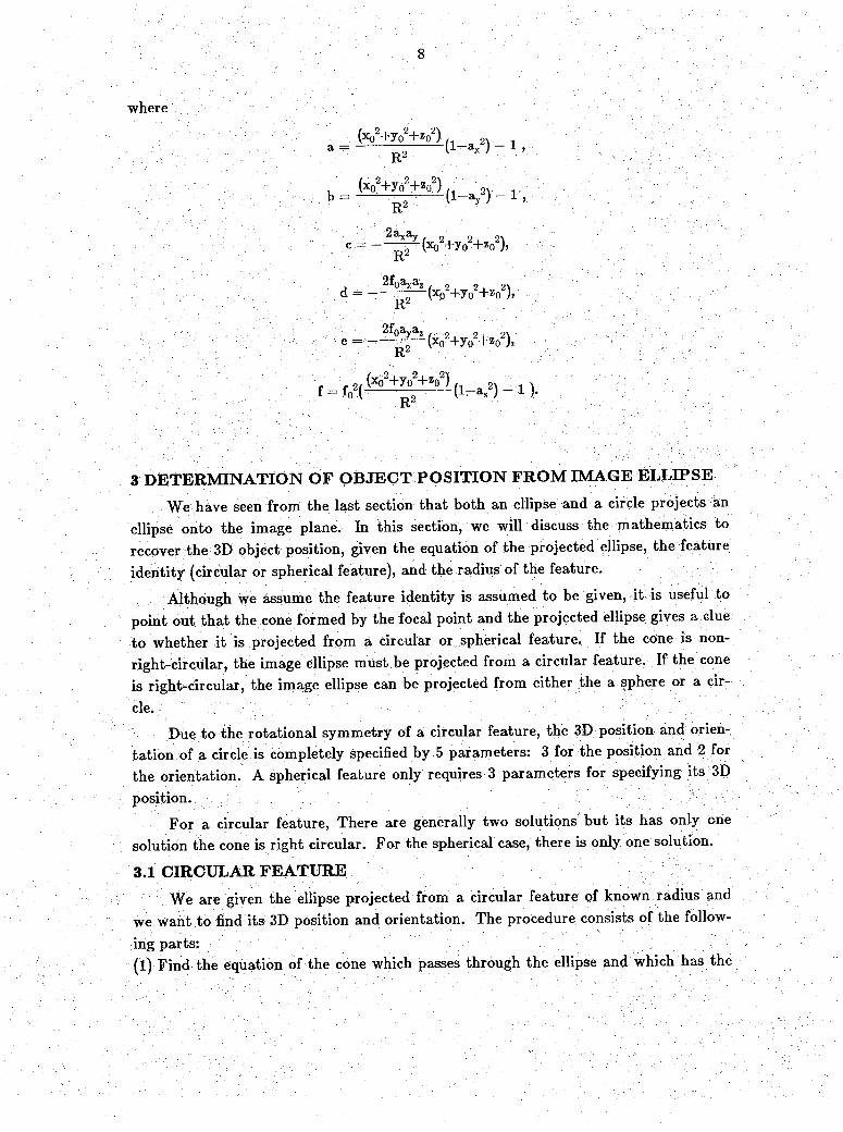
a;= ( V + ^ i W ) i ,
b = W + y | W l (1_ V ) _ i ;
C ■ (xo2+yo2+ zo2)>R2
d = —2f0axaz
(xo2+y02+ zo2)»K“
O2+ -.2).
f = ^ ( (x°2+y{ + *“8)( l - ^ ) - l ) .
3 DETERM INATION OF OBJECT POSITION FROM IMAGE ELLIPSE
We have seen from the last section that both an ellipse and a circle projects an ellipse onto the image plane. In this section, wte will discuss the mathematics to recover the 3D object position, given the equation of the projected ellipse, the feature identity (circular or spherical feature), and the radius of the feature.
Although we assume the feature identity is assumed to be given, it is useful to point out that the cone formed by the focal point and the projected ellipse gives a clue to whether it is projected from a circular or spherical feature. If the cone is nonright-circular, the image ellipse must be projected from a circular feature. If the cone is right-circular, the image ellipse can be projected from either the a sphere or a circle. -
Due to the rotational symmetry of a circular feature, the 3D position and orientation of a circle is completely specified by 5 parameters: 3 for the position and 2 for the orientation. A spherical feature only requires 3 parameters for specifying its 3D position.
For a circular feature, There are generally two solutions but its has only one solution the cone is right circular. For the spherical case, there is only one solution.
3.1 CIRCULAR FEATUREWe are given the ellipse projected from a circular feature of known radiusand
we want to find its 3D position and orientation. The procedure consists of the following parts:(l) Find the equation of the cone which passes through the ellipse and which has the

focal point as vertex relative to the camera frame.(2) Find a new frame of reference in which the cone has the standard form.(3) Find the two planes that intersect the cone in circles having the same radius as the model feature. This will result in two sets of solutions for the position and noripal
vector of the circle.(4) Transform the solution back to the original (camera) frame.
3>1.1 FINDING THE EQUATION OF THE CQNEWe need to find the equation of the cone relative to the camera frame. Figure
3.1.1.1 shows the cone passing through the image ellipse. The camera frame of reference is x -y -z and the image frame is u -v. Let the given equation of the image ellipse
be v ; v \au2+bv24-cuv-Kdu+ev+f == 0. (3.1.1.1)
Many methods have been developed to trace an image ellipse and to find its equation, see [Tsukune, Shirai]. We can thus assume the coefficient (a-f) of the ellipse is known. Each point (u,v) on the image ellipse becomes a line of the cone through (u,v,f0) and (0,0,0), where f0 is the focal length of the camera. The two point form of such a line is (x-0)/(u-0) = (y-0)/(v-0) - (z—0)/(f0—0) which results in ;
(3.1.1.2)fx fy.U = — ,V = "j K
Z Z
Substituting Equation 3.1.i-2 into Equation 3.1.1.1 and rearranging, we have the equation of the cone in terms of the coefficients of the image ellipse (a-f) and the focal
length (f0):Ax2+By2+Cxy-|-Dxz+Eyz+Fz2 = 0. (3.1,1.3)
where A = af02, B = bf02, G = cf02, D = df0, E = ef0, F = f.
3.1.2 FINDING THE NEW REFERENCE FRAME AND CHARACTERI- ZATIQN OF THE CONE
Next we will find a new frame of reference x '-y -z ' in which the cone have a standard form. Since the cone has its vertex at the origin of the camera frame x-y>z, thenew reference frame x -y ’-z’ have the same origin as the .eam«ra-;fr.ame^ .-the-homogeneous transform representing the new frame is a pure rotational matrix, Let F(SXS) represents the rotational partsof the transform matrix. Then the first, second, and third columns of P must be the directions of the x', y', and z' axes relative to x-y- z, respectively [Paul]. The matrix P can also be viewed as a transformation matrix such that if (x,y,z)T is the coordinate of a point in space relative to x-y-z and (x',y',z')T is the coordinate of the same point relative to x'-y'-z', then (x,y,z)T = P(x',y',z')T. Equation 3.1.1.3 can be expressed in terms of a quadratic form Q [Noble]:
[x y z] Q 0, where Q
. C DA I T
BC_2D E p 2 2
(3.1.2.1)

We will now show (in a way similar to [Noble]) that if P is a diagonalizing matrix for Q, or, P -1 QP== Diag(XuX2-xS)) then Equation 3.1.1.3 will be standardized by substituting (x,y,z)T by P(x',y',z')T, which is equivalent to a change of reference frame to the one represented by P. After the substitution, the dot product form of the original cone equation <[x,y,z]T,Q[x,y,z]T> = 0 becomes<P[x',y',z']T,QP[x',y',z']T> = 0. Since multipling vectors on both sides of the dot product by an orthogonal matrix does not change the value of the dot product, we can multiply both sides of the dot product by P ' !, resulting in< [xSy'.z'jTp-1 QP [x'.y'.z']'1̂ = 0, and <[x',y',z']T,A[x',y',z']T> = 0. This can be written as
X,x,2-|-X2y,"-t-X8z'2 = 0. (3.1.2.2)
Compare this equation to that of an cone with its axis aligned with the z’-axis [Salmon];.
= 0. (3.1.2.3)— + ^ - —— = 0.V 2 Ir 2 k 2.. • / - Kx -y . .
From Equations 3.1.1.2-3, we can see that kx, ky, kz is related to X1, X2, and X8. Notice that Equation 3.1.1.2 is still valid if X1, X2, and X3 are replaced by ? X1, f X2, and ? X3, where > is any constant; Similarly, Equation 3.1.1.3 is valid if Tc,, ky, and k, is replaced by »? kx, 77 ky, and t] kz, where rj is any constant. Thus, a multiplying constant is needed in the following equations relating kx, ky, kz and the eigenvalues of Q.
1 ' 1 1 (3.1.2.4)y r a - ’
= P
where p is any real constant. The constant k is unimportant, it is the ratio kx:ky:kz that determines the shape of the cone. 4-s shown in Figure 3.1.2.1, if we intersect the cone of Equation 3.1.2.3 with a plane normal to the cone axis (z’-axis), the intersection will be an ellipse on the intersecting plane and the major axis of the ellipse will line up with either the x ’ or the y ’ axis. It is also known from 3D analytic geometry [Salmon] that if the distance between the plane and the vertex of the cone is kz, then the lengths of the ellipses axes must be 2kx and 2ky.
To summarize, the followings must be true for P=[C1C2C3]:(1 ) P - 1QP=A=Diag(XuX2jX3).(2) P represent a right-handed coordinated frame x’-y’-z’.(3) The z’-axis (e3) is the same as the cone axis. Moreover, the positive direction is chosen such that the z’-axis points in the direction the camera is pointing to.(4) We follow a convention for the assignment of X1 and X2 such that | X11 > j X2 I - so that if we intersect the cone with a plane parallel to the x ’-y’ plane, the major axis of the resulting ellipse will be parallel to the y ’-axis.
To find P, we first find the eigenvalues and normalized eigenvectors of Q by a computer program (such as the devcsf subroutine from the IMSL mathematical

library [IMSLj-.). Let Mu M2, and Ms be the calculated eigenvalues and let f l5 f2j and f3 be the corresponding normalized eigenvectors. The difference between the set {mum2,Ps} and the set (X1jX2jX3) is that they are not ordered in the same way. The differences between the set { f1(f2,f3) and the set IeljC2Je3) are both in the ordering (which is the same ordering as for the eigenvalues) and in the scaling factpr of ±1. We will discuss how to assign X1, X2, and X3 from the calculated eigenvalues Zfij ^2> aud Zi3 SO that criteria (3) and (4) are satisfied. Once the calculated eigenvalues {mi,M2,Ps} are ordered to form IX1jX2jX3), the same ordering can be applied to the calculated eigenvectors | T1,^,fj) to form IeljC2jC3). The signs 'OfTljJf2, and f3 will also have to fie changed to satisfy criteria (2) and (3).
The method for finding P ( or [eie2e3] ) depends on whether the cone is right- circular or not. A right-circular cone is one that the intersection between the cone and a plane normal to its axis results in a circle. If a second degree cone is not right- circular, the intersection and the plane is an ellipse. A cone..is; right ciycu)ar;jpr^eji. Icx=Icy, which is equivalent to X1=X2 (see Equation 3.1.2.4). Because of the repetition of eigenvalues, the two corresponding eigenvectors C1 and e2 are not unique. This is expected because there are infinite number of coordinate frames ( Ie1C2C3] ) in which the right-circular cone has standard forms. Any frame whose z-axis (e3) is along the cone axis and whose origin is at the cone vertex will have the standard cone equation of Equation 3.I.2.3. If there are no repeated eigenvalues, or X1̂ X25A 3, the cone is not right circular. In this case, there is a unique set of real orthonormal eigenvectors {
fiT2»f3 }> except the ±1 scaling factor.Now we are ready to find X3 and e3. Comparing Equation 3.1.2.2 to Equation
3.1.2.3, X1 and X2 must have the same signs and X3 must have a different sign. Tfiusj we can find X3 and e3 based on the polarities of the calculated eigenvalues Mu M2, and
Ms- - :: . ; - ' ' ■ -V"- , -- 'V- V . " . V v :I X3 = , . v|;. v (3.1 2.5)
where Md is chosen from the calculated eigenvalues Mu /*2 and / i 3, and z*d fias a different sign from the remaining two eigenvalues. The corresponding eigenvector fd must be along the z-axis of the cone. The positive direction of e3 is chosen to satisfy Criterion
- ' V v - . V ^ V V - . V r ) v V f i f i f iIf the dot product fd.(0,0Jl)T > 0, then
' e3 = fd . (^*12.6)
If fd.(OjOjI)1 < 0, then
e3 = —fd . (3.I.2.7)
Notice that the dot product cannot be zero. Otherwise only the side of the circularfeature can be seen. The circle will project a fine to the camera screen and this contradicts the assumption of an elliptical projection.

When finding X2 and e2, Criterion (4) must be satisfied. Let { W1, w2 } be the remaining eigenvalues from { /q, //2, /*3 } when /zj is deleted, We also let gj and g2 be the two eigenvectors corresponding to W1 and w2.
If I W11 < I W2 I , then
■■■ ' ; V - V ' ■' - Xg = CJj j (3.1.2,8)
: ■ -v:, ■ v - v . v ■ ■ e2 = gl • (3.1.2.9)
If I W2 I < I W1 I , then
. v j ; ; ; V v r ^ r vV ' ; Xg = 2̂ J (3.1.2.9)
M''Il>°\ (3.ii2.10)
If I co21 = I W11 , the cone is right-circular and there are infinite choices for selecting e2. We can select any vector on the plane spanned by g, and g2. In our implementation, We arbitrarily select g2 and Equations 3.1.2.9-10 are used to find X2 and e2.
Finally, X1 must be the eigenvalue not yet chosen. ex must be the corresponding eigenvector. However, C1 will not be calculated from the remaining eigenvector, it will be calculated by taking the cross-product of e2 and e3, to ensure the right- handedness requirement of Criterion (2).
C1 = C2Xe3 . (3.1.2.11)
Now that C1, e2, e3 are found, the transformation matrix P is found. Also, since X1, X2, and X3 are found, kx, ky, and kz can be found by Equation 3.1.2.3 and the geometrical characteristics of the cone is now known. There are infinite possible choices for P is not unique if the cone is right-circular, because of one degree of rotational freedom. For the case of the non-right-circular cone, there are two possible choices, one having its x and y axes in the opposite directions as the those of the other choice. .
3.1.3 CIRCULAR SEC TIO N S OF THE C O N EAfter the transformation of frame of reference using P, we have the standard
equation of a cone in the form of Eqqation 3.1.2.3. The cone is shown in Figure 31.2.1, with respect to the P frame (x'—y'—z' frame). The goal is to find all the ways to cut the cone such that a circle with the desired model diairieter will result. Since the intersection curves are similar if the sectioning planes are parallel [Salmon], we can divide the task into two parts. First we will find the orientations (surface normals) of the planes that intersect the cone in circles. Then we will translate the planes along the cone axis to find the circles with the desired diameter.
From [Salmon], there are only 2 plane orientations (surface normals) that will result in circular sections, see Figure 3.I.3.I. Furthermore, when ky>kx, the two planes of circular section which also passes through the origin can be derived from the

following equation:
x'2k / ky2 ) ky2 k22
(3.1.3.1)
Factorizing the above equation and using Equation 3.1.2.4, we have the following two sectioning planes:
X1 I - | X2 | ,| x 2 | + | x 3 | x '
(3.1.3.2)
Notice that both sectioning planes passes through the y-axis, and that the projections of the planes to the x ’-y’ plane are two lines. These two planes only gives the plane orientations for circular sections; they do not section the cone in circles with the model radius. In fact, they intersect the cone at one point - the origin of the x ’-y’-z’ reference frame.
We will noTV translate the planes to obtain circular sections with the correct model radius. Figure 3.1.3.2 shows the cone and the sectioning planes projected onto the x ’-z’ plane. The equations of the lines representing the cone can be found by substituting 0 into y' in Equation 3.1.2.2 and knowing that X1 and X3 have Opposite signs.
If we translate the planes of Equation 3.1.3.2 along the z-axis by I, we can easily calculate the radius f of the resulting circle. The translated planes have the equations
v=±;V I X11 — IX2 II X2 I + 1X3 I
x' + I (3.1.3.4)
By similar triangles shown in Figure 3.1.3.2, we can then find out how much we have to translate the plane in order to obtain circular sections of the required model radius.
Let s be the translation in the z’ direction so that the planes of Equation (3.1.3.4) will have circular sections of model radius R after the translation. We can calculate s by
(3.1.3.5)
The symbolic form of r is half of the distance between p i and p2 or between ql and q2 in Figure 3.I.3.2. The points p i, p2, ql and q2 can be calculated by intersecting the lines represented by Equation (3.1.3.3) and Equation (3.1.3.4). The algebraic manipulation is simpler if it is carried out using kx, ky, kz, instead of X1, X2, and X3vIn the final answer, ky, ky, kz is converted back to X1, X2, and X3. The conversion between kx, ky, k2 and Xi,;X2, X3 is made by using Equation (3.1.2.4).
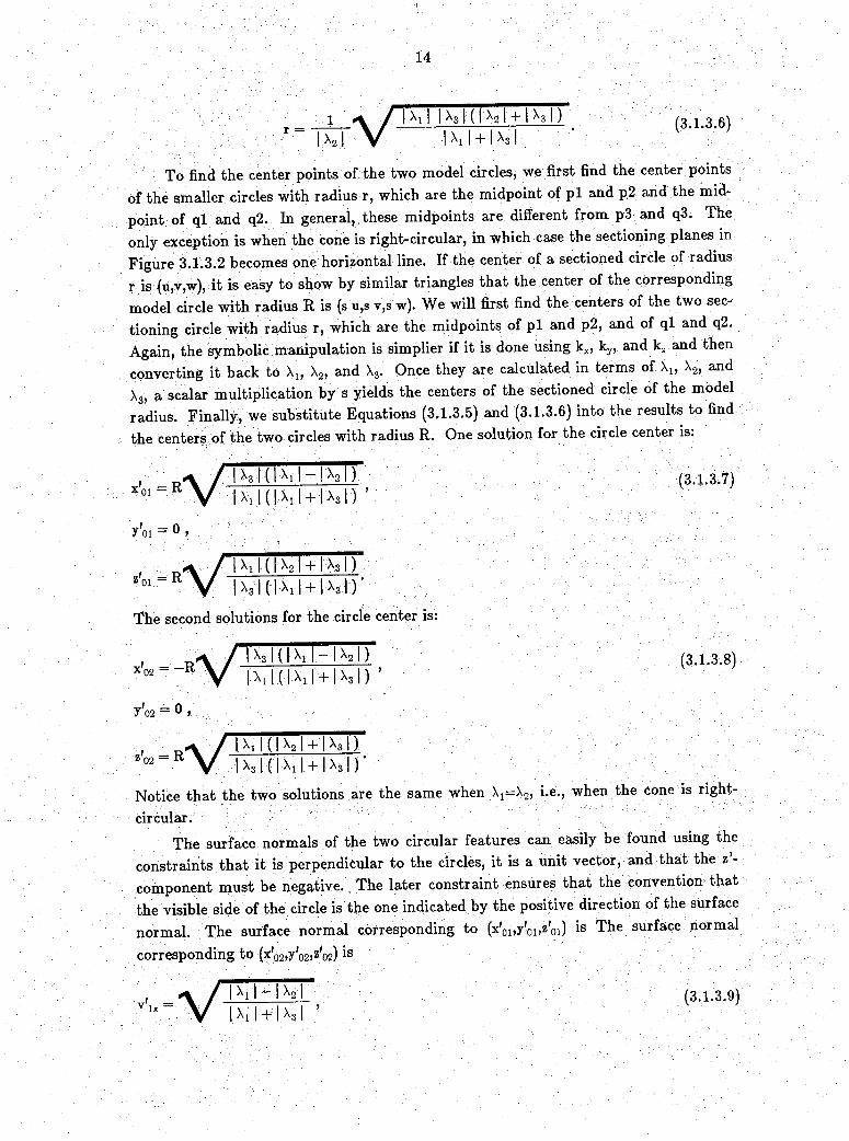
r IIX2I
I Xi I IX3 1 ( IX2 I + 1X3 I) I X11 + 1X3 I
(3 1.3.6)
To find the center points of the two model circles, we first find the center points of the smaller circles with radius r, which are the midpoint of p i and p2 and the midpoint of ql and q2. In general, these midpoints are different from p3 and q3. The only exception is when the cone is right-circular, in which case the sectioning planes in Figure 3.1.3.2 becomes one horizontal line. If the center of a sectioned circle of radius r is (u,v,w), it is easy to show by similar triangles that the center of the corresponding model circle with radius R is (s u,s v,s w). We will first find the centers of the two sectioning circle with radius r, which are the midpoints of p i and p2, and of ql and q2. Again, the 'symbolic manipulation is simplier if it is done using kx, ky, and kz and then converting it back to X1, X2, and X3. Gnce they are calculated in terms of X1, X2, and X3, a scalar multiplication by s yields the centers of the sectioned circle of the model radius. Finally, we substitute Equations (3.1.3.5) and (3.1.3.6) into the results to find the centers of the two circles with radius R. One solution for the circle center is:
I X3I ( I x 1I - I x 2I ) : IX11 ( IX11 + 1X3 I)
(3.1.3.7)
y'oi = 0 >
, a / I x1 1(1 x2 | + 1 X3 1)V I xj I ( I x 1I ^ i x j I ) -The second solutions for the circle center is:
x'02 = -R
y'o2 - 0 >
Z*02 = R
I X11 ( I X1 1 + 1 x3 | )(3.1 3.8)
I X1 I ( I X2 + 1X3 I )IX31 ( IX11 + 1X3 I)
Notice that the two solutions are the same when X1=X2, i.e., when the cone is right-
circular.The surface normals of the two circular features can easily be found using the
constraints that it is perpendicular to the circles, it is a unit vector, and that the z - component must be negative. The later constraint ensures that the convention that the visible side of the circle is the one indicated by the positive direction of the surface normal. The surface normal corresponding to (x'oDy'oi^oi) is The surface normal
corresponding to (x'o2,y'o2>z,o2) is \
V11^ I IX11 — IX2 I
I x 1J - I - I x 3 I(3.1 3.9)

Ax
I X2 | + I X3J I X1 1 + 1A i
I Ni I ~ ~ I X2I I X1 I + 1 X3 1
(3.1.3.10)
Ay = 0 »
A * \ / I x2 1 + 1 x3 i I V I + I X 3 I
The above solutions for the centers and the suface normals of the circles are given relative to the x ’-y’-z’ frame. The transformation matrix P will bring them back to the x-y-z frame: [x0i,yoi>zoi]T= P[*loi>y,oi>z,oi]T and [VixlViy,viz]T= F * ix, viy,viz] , where 1=1,2, and (x0i,yoi,zoi) and (x02,Y021Z02) are the two solutions for the circle centers and (vlx,vly,vl2) and (v2x,v2y,v2z) are the two corresponding surface normals, all relative to the x-y-z frame (camera frame). Recall that P is composed of the 3 eigenvectors of
Q:
©i e2 e3]eIx e2x e3x eIy e2y e3y eIz e2z e3z
(3.1.3.11)
Expanding P into its elements, we have the solutions with respect to the cameraframe. One solution for the circle center is:
X0I = ClxR ' ^I I X3 I ( I X j I — I X2 | ) r » * \ f
J | X i l ( | X , l + | X 3 | ) ox VI X1 K I x 2 l + 1 x 3 I T ; ; ( 3 . 1 . 3 . 1 2 )I X3 I ( I Xi I + 1 x3 1 )
O Il C rtf >
/ I X 3 K I X i - I X 2 1) ^ . R v // I x , I ( I Xi I + 1 X3 I ) + V
I X1 K I X2 1 + 1 x 3 1 ) I ^3 I ( I I + I ^ 3 1 )
zoi “ e i zR ^/ I x 3 | ( Xj — X2 ] ) F
A I Xv I ( I X1 1 + I X3 I ) “ V -I I ( I ^ 2 I + I I I x3 K I X1 1 + 1 x3 1 )
The second solution for the circle center is: ' v K v + '
IX3 I ( IX11 — IX2 I)I X11 ( | X11 + I X31)
Ix3Kr x1I - I X 2ITI X1 I ( I X11 + I X3 I )
I X3K I X 1M X 2 I T I X11( I-Xil + 1 x3 1)
IX1 ( I X2 I + IX3 )IX3 K IX11 + 1X31)
I X i | ( I X 2 1 + 1 x 3 1 ) I X 3 1 ( I X i I + 1 x 3 | )
I X t | ( I x 2 1 + 1 x 3 1 )I x 3 1 ( I X 1 1 -1- 1 X 3 - J- )
(3.1.3.13)

16
The surface normal corresponding to [x01,yPi,z0i]T is:
Vlx
v Iy
Viz
I I ~ I 2̂ I I ^ l I + I ^ 3 I
I I ~ I X2 I X 1 I + I ^ 3 I
: I l̂ I ~ I X2 [ I X 1 | + | X 3 |
I X 2 | + . I X 3 II X 1 | + | ^ 3 I
I X 2 | + | X 3 |I ^ l I + I ^ 3 I
I X 2 | - f I X 3 | I X i | + | X 3 |
The surface normal corresponding to [x02,y02,z02]T is
(3.1.3.14)
v 2x
V2y
V2z
~ I X j | — [ X 2 | I X i | + | X 3 |
I I ~ I X2 I I ^ l I + I ^ 3 I
I l̂ I ~ I X2 I I X 1 | + | X 3 I
I X 2 | + [ X 3 | I X i I + I X 3 ]
I X 2 I + I X 3 I I X 1 I + 1 X 3 I
I X2 1 + 1 x 3, 1 I x 11 + 1X3 I
(3.1.3.15)
From the above equations for the centers and the surface normals for the solutions, we can see th a t there are two solutions in general. However, when X 1 = X 2 , there is only one solution because both solutions become the same. Geometrically, there is only one solution if the surface normal of the circle points to focal point exactly.
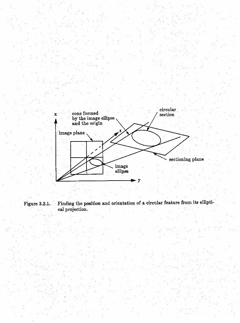
3.2 SPHERICAL FEATUREIf we are given the ellipse projected from a spherical feature of known radius R,
we can find the 3D position of its center. This is shown in Figure 3.2.1 The procedure involved is similar to the case of the circular feature. It consist of the following parts:(1) Find the equation of the cone th a t passes through the ellipse and which has the origin as vertex. The resulting cone must be a right-circular cone.(2) Find a new frame of reference in which the cone has the standard form.(3) Find the position of the spherical feature in the new frame of reference.(4) Transform the solution back to the original (camera) frame.
P arts (I) and (2) are the done exactly the same way as the circular case and will not be repeated here. It is im portant to point out tha t the resulting cone will always be right-circular for the spherical case and therefore X 1 / = X 2 and kx=ky. We will denote X 1 and X 2 by X r , and kx and ky by kr.
P a rt (3) is considerably simpler compared to the equivalent part for the circular case. Given a right-circular cone, there is only one way tha t a sphere of radius R can
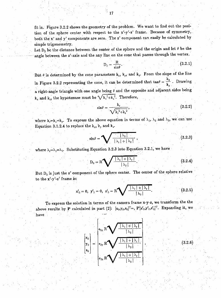
fit in. Figure 3.2.2 shows the geometry of the problem. We want to find out the position of the sphere center with respect to the x’-y’-z’ frame. Because of symmetry, both the X 5 and y J components are zero. The z5 component can easily be calculated by simple trigonometry.Let D0 be the distance between the center of the sphere and the origin and let 9 be the angle between the zr-axis and the any line on the cone that passes through the vertex.
D0 Rsin#
(3.2.1)
But 0 is determined by the cone parameters kx, ky, and kz. From the slope of the linekx .p. .
in Figure 3.2.2 representing the cone, it can be determined that tan6 = — • Drawing
a right-angle triangle with one angle being 0 and the opposite and adjacent sides beingkx and kz, the hypotenuse must be V kx2+kz2. Therefore,
sin 0 = — = r , (3-2.2)V w
where kr==kx=kr To express the above equation in terms of X1, X2 and X3, we can use Equation 3.1.2.4 to replace the kx, ky and kz.
sin0 V 1 IX3II X r I + I X 3 I
where Xr=X^=X2- Substituting Equation 3.2.3 into Equation 3.2.1, we have
D0 = R1V Xi I + 1 K \I x 3 I
(3.2.3)
(3.2.4)
But D0 is just the z’ component of the sphere center. The center of the sphere relative to the x ’-y’-z’ frame is:
x'0 = 0, y'0 0, z;0I Xi I -f I Xr I
I X3 I(3.2.5)
To express the solution in terms of the camera frame x-y-z, we transform the the above results by P calculated in part (2): [x0,yo,zo]T=vF[x,o,y;o>z,o]T' Expanding it, we have ■'
x O
ToZ0
I Xj I + I Xr I [X3 I
I Xj l + I XrIX3I
I Xi I -t I Xr II X 3 I
(3.2.6)
18
4 CO N CLU SIO NWe have written a program to find the 3D position and orientation of a circular
feature from the elliptical projection of the feature. The results are correct for all the test cases, which includes both elliptical and right-circular cones. We have also extended this method to spherical features. The complete mathematics for both the circular case and the spherical case will be recorded in a technical report.
4 ACKNOW LEDGEM ENTThe authors Want to thank David Marimont for valuable discussions and for giv
ing usi his Ph.D. dissertation.

LIST OF REFERENCES
[Fischler] M.A. Fischler and R.C. Bolles, "Random Sample Consensus: A Paradigm for Model Fitting with Applications to Image Analysis and Automated Cartography," Communications of the ACM, June 1981, vol. 24, no. 6, pp. 381-395.
[Ganapathy] S. Ganapathy, "Decomposition of Transformation Matrices for Robot Vision," in IEEE Proc. Int. Conf. Robotics and Automation, 1984.
[Haralick_a] R. M: Haralick, Y. H. Yu, L. T. Watson, L. G. Shapiro, "Matching Wire Frame Objects from Their Two Dimensional Perspective Projections," Pattern Recognition, Vol. 17, No. 6, 1984.
[Haralick_b] R. M. Haralick, "Solving Camera Parameters from the Perspective Projection of a Parameterized Curve,” Pattern Recognition, Vol. 17, No. 6, 1984.
[IMSL] IMSb Inc., IMSL Math/Library User’s Manual, IMSL Inc., Houston, Texas, 1987.[Lowe] D. Lowe, "Perceptual Organization and Visual Recognition,” Ph.D. dissertation, Stanford
University, Stanford, CA, September 1984.[Marimont] D.H. Marimont, "Inferring Spatial Structure from Feature Correspondences,” Ph.D. disserta
tion, Stanford University, Stanford, CA, March 1986.[Mulgaonkar] P.G. Mulgaonkar, "Analysis of Perspective Line Drawings Using Hypothesis Based Reasoning,"
Ph.D. dissertation, Virginia Polytechnic Institute and State University, 1984.[Noble] B. Noble, Applied Linear Algebra, Prentice Hall, Englewoods, N. J., 1969.[Paul] R. P. Paul, Robot Manipulators: Mathematics, Programming, and Control, MIT Press, Cam-
bridge, Massachusetts, 1981.[Salmon] G. Salmon, A Treatise on the Analytic Geometry of S Dimensions, Vol. I, Longmans, Green &
Co., London, 1912.[Shirai] Y.Shirai, "Recognition of Real-World Objects Using Edge Cue, in Computer Vision System,
eds. A.R.Hanson and E.M.Riseman, Academic Press, New York, NY, 1978.[Shiu] Y.C. Shiu, R.P. Paul, Shaheen Ahmad. "Using Visual Servoing in Robotic Tasks," TR-ERC
86-10 , Purdue University, West Lafayette, In. , 1986.[SMP] Inference Corporation, SMP Reference Manual, Inference Corporation, Los Angeles, CA, 1983.[TsaiI R Y. Tsai, "A Versatile Camera Calibration Technique for High-Accuracy 3D Machine Vision
Metrology Using Off-the-Shelf TV Cameras and Lenses," IEEE Journal of Robotics and Auto- maiion, Vol. RA-3, No. 4, 1987.
[Tsukune] H. Tsukune and K. Goto, "Extracting Elliptical Figures from an Edge Vector Field," in Proc. IEEE Conf. Computer Vision and Pattern Recognition, Washington, D.C., June 1983.
[Wolf] P.R. Wolf, Elements of Photogrammetry, 2nd ed., McGraw-Hill, New York, 1983.

U
image plane or projection planecenter of
projection _
camera frame x-y-z
Figure 2.1.1. The camera frame x-y-z.
Figure 2.1.2. The convention that the surface normal points outward from the invisible side of the circle to the visible side.
surfacenormal
elliptical projection of circular featureprojection jplane x /
3D circular feature
- Y 1-Z 1 frame
camera frame x-y-z
Figure 2.1.3. Thex'—/ —z' frame, where the z-axis lines up with the surface normal ofthe circular feature.
z',zM
Figure 2.1.4. The center of te circular feature relative to the "Xl-Y1-Z 1 frame and the Xn-Y 11-Z tl frame.

I
■̂ £ure Finding the ratio kz/ky in terms of R and D0
circular / sectionConeformed
by the image ellipse and the origin
image plane
sectioning planeimageellipse
Figure 3.2.1. Finding the position and orientation of a circular feature from its elliptical projection.

plane parallel
top view
Figure 3.I.2.I. The elliptical cone
Figure 3.1.3.1. The two planes of circular section

i \
sectioning planes that result in circles of radius R
planes of circular section
-► x' ► x'
Figure 3.I.3.2. Finding the two sectioning planes that result in circles with radius R.

X
Figure 3.2.1. Finding the position of a spherical feature from its elliptical projection.
Figure 3.2.2. Solution for the spherical feature position.