3d homogenized limit analysis of masonry buildings
TRANSCRIPT

III European Conference on Computational Mechanics Solids, Structures and Coupled Problems in Engineering
C.A. Mota Soares et.al. (eds.) Lisbon, Portugal, 5–8 June 2006
3D HOMOGENIZED LIMIT ANALYSIS OF MASONRY BUILDINGS SUBJECTED TO HORIZONTAL LOADS
G.Milani1, P.B.Lourenço2, A. Tralli1 1 Department of Engineering, University of Ferrara
Via Saragat 1 44100 Ferrara, Italy [email protected] [email protected]
2 Department of Civil Engineering, University of Minho, School of Engineering 4800-058 Azurem, Guimarães, Portugal
Keywords: Masonry, limit analysis, kinematic approach, 3D.
Abstract. The current confidence in the ability to provide buildings with adequate resistance to horizontal actions does not extend back to historic and existing masonry structures. Fur-thermore, it has been shown that the high vulnerability of historical centers to horizontal ac-tions is mostly due to the absence of adequate connections between the various parts, especially when wooden beams are present both in the floors and in the roof [1]. This charac-teristic leads to overturning collapses of the perimeter walls under seismic horizontal accel-eration and combined in- and out-of-plane failures. Even if limit analysis is not sufficient for a full structural analysis under seismic loads, it can be profitably used in order to obtain a simple and quick estimation of collapse loads and failure mechanisms. Up to now, simplified limit analysis methods are at disposal to the practitioners both for safety analyses and design of strengthening [2]. Nevertheless, in some cases these methods are based on several simpli-fications, one of which is an a-priori assumption of the collapse mechanics combined with the separation of in- and out-of-plane effects. In this paper, the micro-mechanical model pre-sented by the authors in [3] and [4] for the limit analysis of respectively in- and out-of-plane loaded masonry walls is utilized in presence of coupled membrane and flexural effects. In the model, the elementary cell is subdivided along its thickness in several layers. For each layer, fully equilibrated stress fields are assumed, adopting polynomial expressions for the stress tensor components in a finite number of sub-domains. The continuity of the stress vector on the interfaces between adjacent sub-domains and suitable anti-periodicity conditions on the boundary surface are further imposed. In this way, linearized homogenized surfaces in six dimensions (polytopes) for masonry in- and out-of-plane loaded are obtained. Such surfaces are then implemented in a FE limit analysis code for the analysis at collapse of entire 3D structures. Two examples of technical relevance are discussed in detail and comparisons with results obtained by means of standard FE codes are provided.

G. Milani, P.B. Lourenço and A. Tralli
2
1 INTRODUCTION The evaluation of the ultimate load bearing capacity of entire masonry buildings subjected
to horizontal loads is a fundamental task for the design of brickwork structures. Furthermore, many codes of practice, as for instance the recent Italian O.P.C.M. 3431 [5] [6], require a static non linear analysis for existing masonry buildings, in which a limited ductile behavior of the elements is taken into account, featuring failures connected to rocking, shear and di-agonal cracking of the walls.
Nowadays, several models for the analysis of masonry buildings are at disposal, but the approach based on the use of averaged constitutive equations seems to be the only one suit-able to be employed in a large scale finite element analysis [7]. In fact, a heterogeneous ap-proaches based on a distinct representation of bricks and joints seems to be limited to the study of panels of small dimensions, due to the large number of variables involved in a non linear finite element analysis. Therefore, alternative strategies based on macro-modeling have been recently developed in order to tackle engineering problems. Nevertheless, macro-approaches require a preliminary mechanical characterization of the model, which has to be derived from experimental data [8].
In this framework, homogenization techniques can be profitably used for the analysis of large scale structures. In this case, in fact, both mechanical properties of constituent materials and geometry of the elementary cell are taken into account only at a cell level, so allowing the analysis of entire buildings through standard finite element codes. Furthermore, the applica-tion of homogenization theory to the rigid-plastic case [9] requires only a reduced number of material parameters and provides important information at failure, such as limit multipliers, collapse mechanisms and, at least on critical sections, the stress distribution [10].
In this paper, the micro-mechanical model presented by the authors in [3] and [4] for the limit analysis of respectively in- and out-of-plane loaded masonry walls is utilized in presence of coupled membrane and flexural effects. In the model, the elementary cell is subdivided along its thickness in several layers. For each layer, fully equilibrated stress fields are as-sumed, adopting polynomial expressions for the stress tensor components in a finite number of sub-domains. The continuity of the stress vector on the interfaces between adjacent sub-domains and suitable anti-periodicity conditions on the boundary surface are further imposed. In this way, linearized homogenized surfaces in six dimensions (polytopes) for masonry in- and out-of-plane loaded are obtained. Such surfaces are then implemented in a FE limit analy-sis code for the analysis at collapse of entire 3D structures. Two examples of technical rele-vance are discussed in detail and comparisons with standard FE codes are provided.
In Section 2, the micro-mechanical model adopted for obtaining masonry homogenized polytopes is recalled, whereas in Section 3 the FE upper bound approach is presented. The method is based on a triangular discretization of the structure, so that the velocity field interpolation is linear inside each element. Plastic dissipation can occur for in-plane actions both in continuum and in interfaces, whereas out-of-plane dissipation takes place only at the interface between adjacent triangles. Two meaningful structural examples are treated in detail in Section 4, concerning a large scale masonry building located in Ferrara (Italy) and an ancient house already studied by De Benedictis et al. in [11]. The reliability of the proposed model is assessed through comparisons with results obtained by means of standard non-linear FE approaches.
2 IN- AND OUT-OF-PLANE HOMOGENIZED FAILURE SURFACES A masonry wall Ω constituted by a periodic arrangement of bricks and mortar disposed in
running bond texture is considered, as shown in Figure 1-a. As pointed out by Suquet in [9],

G. Milani, P.B. Lourenço and A. Tralli
3
homogenization techniques combined with limit analysis can be applied for the evaluation of the homogenized out-of-plane strength domain homS of masonry. Under the assumptions of perfect plasticity and associated flow rule for the constituent materials, and in the framework of the lower bound limit analysis theorem, homS can be derived by means of the following (non-linear) optimization problem (see also Figure 1):
( )[ ][ ]
( ) ( )
∈∀∈∈∀∈∂
==
=
=
=∫
∫
×
×
)(;)(onperiodic-anti)()(
)(1
)(1
|int
3hom
fYSYSeYdcdiv
bdVyY
adVY
S
bbmml
hY
hY
yyσyyσσn
0nσ0σ
σM
σN
NM,
( 1 ) where:
- N and M are the macroscopic in-plane (membrane forces) and out-of-plane (bending moments and torsion) tensor;
- σ denotes the microscopic stress tensor; - n is the outward versor of lY∂ surface, Figure 1-a; - lY∂ is defined in Figure 1-a; - [ ][ ]σ is the jump of micro-stresses across any discontinuity surface of normal intn ,
Figure 1-c; - mS and bS denote respectively the strength domains of mortar and bricks; - Y is the cross section of the 3D elementary cell with 03 =y (see Figure 1) Y is
its area, V is the elementary cell, h represents the wall thickness and ( )321 yyy=y ;
- condition ( 1-c ) imposes the micro-equilibrium with zero body forces, usually ne-glected in the framework of the homogenization theory;
- anti-periodicity condition ( 1-e ) requires that that stress vectors σn are opposite on opposite sides of lY∂ , Figure 1-c, i.e. 2
)(1
)( nn nm σσ −= . In order to solve ( 1 ) numerically, the simple admissible and equilibrated micro-mechanical model proposed in [4] is adopted. The unit cell is subdivided into a fixed number of layers along its thickness, as shown in Figure 1-b. For each layer out-of-plane components 3iσ ( 3,2,1=i ) of the micro-stress tensor σ are set to zero, so that only in-plane components ijσ ( 2,1, =ji ) are considered active. Furthermore, ijσ ( 2,1, =ji ) are kept constant along the
Li∆ thickness of each layer, i.e. in each layer ),( 21 yyijij σσ = . For each layer one-fourth of the REV is sub-divided into nine geometrical elementary entities (sub-domains), so that the entire cell is sub-divided into 36 sub-domains (see [4] for further details and Figure 1-b).
For each sub-domain )(k and layer )( Li , polynomial distributions of degree (m) in the variables ( )21 , yy are a priori assumed for the stress components. Since stresses are polyno-mial expressions, the generic ij th component can be written as follows:
( ) ),(),(),( LLL ikTikij
ikij Yσ ∈= ySyX ( 2 )

G. Milani, P.B. Lourenço and A. Tralli
4
where: - ( ) [ ]2
22121211 yyyyyy=yX ;
- [ ])6)(,()5)(,()4)(,()3)(,()2)(,()1)(,(),( LLLLLLL ikij
ikij
ikij
ikij
ikij
ikij
ikij SSSSSS=S is a vector represent-
ing the unknown stress parameters of sub-domain )(k of layer )( Li ; - ),( LikY represents the k th sub-domain of layer )( Li .
The imposition of equilibrium inside each sub-domain (with zero body forces, as usual in homogenization procedures), the continuity of the stress vector on interfaces and the anti-periodicity of σn permit a strong reduction of the number of independent stress parameters. For the sake of conciseness, we refer the reader to [3] for further details.
Elementary assemblage operations on the local variables allow to write the stress vector ),(~ Likσ of layer Li inside each sub-domain as:
( ) ( ) layersidomainssubk Liikik LLL num.,,1num.,,1~~~ ),(),( =−== SyXσ ( 3 )
where ( )LiS~ is the vector of unknown stress parameters of layer Li .
(k)(r)(q)
(k-r) interface
(i-k) interface
2 13
89 7
6 5 4
Mortar Brick
1011
1718 16
15 14 13
12
20 1921
2627 25
24 23 22
2829
3536 34
33 32 31
30
n(n)2
n2
n1
(m)
1
Yl
(n)n
(m)
y1
y2
y3
Layer i
Each layer is subdivided in 36
sub-domains
Y
y1
y2
wall thickness is subdivided in layers
Imposition of internal equilibrium, equilibrium on
interfaces and anti-periodicity
n int
Elementary cell V
y1
y 2
y3
b/2b/2
b
ev
eh
eh
a/2
a/2
a
h
y1
y 2
y3
Yl
Elementary cell
X 2
X 1
Y3
+
n
n
Y
L
-a -b -c
Figure 1: The micro-mechanical model proposed. -a: the elementary cell. –b: subdivision in layers along the thickness and subdivision of each layer in sub-domains. –c: imposition of in-
ternal equilibrium, equilibrium on interfaces and anti-periodicity.
As already pointed out, once that an equilibrated polynomial field in each layer is obtained, the proposed out-of-plane model requires a subdivision ( Ln ) of the wall thickness into several layers (Figure 1-a), with a fixed constant thickness Li nt
L/=∆ for each layer. This allows to
derive the following simple (non) linear optimization problem:
G. Milani, P.B. Lourenço and A. Tralli
5
[ ]( )
=−=
∈=
==
=
=
≡ Σ
∫∫
)(ofnumber,,1)(ofnumber,,1)(~)(~~~)(~~
)(~~
)(~~max
),(),(
),(),(
,
),(3
,
),(
hom
glayersifdomainssubkeSdc
bdVy
adV
thatsuchS
L
ikik
ikik
ik
ikik
ik
LL
LL
L
L
L
L
σSyXσ
nMNΣ
σM
σN
λ
λ
( 4 )
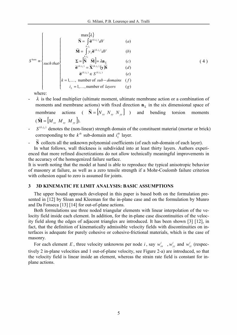
where: - λ is the load multiplier (ultimate moment, ultimate membrane action or a combination of
moments and membrane actions) with fixed direction Σn in the six dimensional space of membrane actions ( [ ]yyxyxx NNN=N~ ) and bending torsion moments
( [ ]yyxyxx MMM=M~ ).
- ),( LikS denotes the (non-linear) strength domain of the constituent material (mortar or brick) corresponding to the thk sub-domain and th
Li layer. - S~ collects all the unknown polynomial coefficients (of each sub-domain of each layer).
In what follows, wall thickness is subdivided into at least thirty layers. Authors experi-enced that more refined discretizations do not allow technically meaningful improvements in the accuracy of the homogenized failure surface. It is worth noting that the model at hand is able to reproduce the typical anisotropic behavior of masonry at failure, as well as a zero tensile strength if a Mohr-Coulomb failure criterion with cohesion equal to zero is assumed for joints.
3 3D KINEMATIC FE LIMIT ANALYSIS: BASIC ASSUMPTIONS The upper bound approach developed in this paper is based both on the formulation pre-
sented in [12] by Sloan and Kleeman for the in-plane case and on the formulation by Munro and Da Fonseca [13] [14] for out-of-plane actions.
Both formulations use three noded triangular elements with linear interpolation of the ve-locity field inside each element. In addition, for the in-plane case discontinuities of the veloc-ity field along the edges of adjacent triangles are introduced. It has been shown [3] [12], in fact, that the definition of kinematically admissible velocity fields with discontinuities on in-terfaces is adequate for purely cohesive or cohesive-frictional materials, which is the case of masonry.
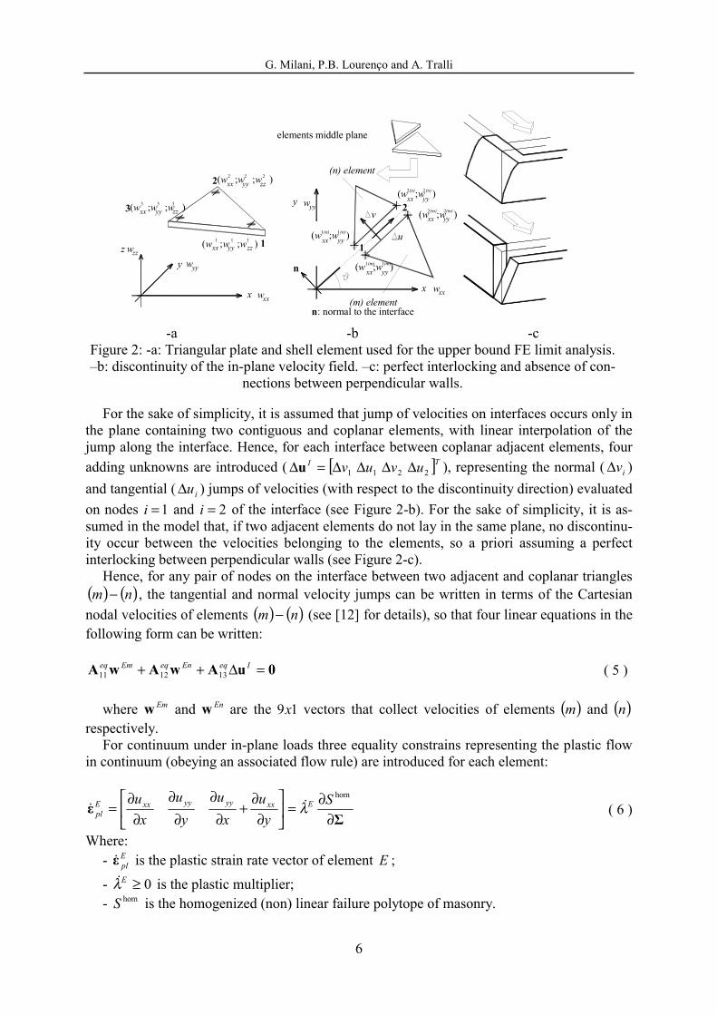
For each element E , three velocity unknowns per node i , say ixxw , i
yyw and izzw (respec-
tively 2 in-plane velocities and 1 out-of-plane velocity, see Figure 2-a) are introduced, so that the velocity field is linear inside an element, whereas the strain rate field is constant for in-plane actions.
G. Milani, P.B. Lourenço and A. Tralli
6
x w xx
y w yy
z w zz1xx yy
1 1
zz1
2 xx yy2 2
zz2
3(w ;w ;w )xx yy3 3
zz3
1
2
u
n
xx yy
v
(w ;w )xx yy
(w ;w )xx yy1(n)
xx yy
w yy
w xx
n: normal to the interface
x
y
(m) element
(n) element
1(n)
1(m) 1(m)
2(n) 2(n)
2(m) 2(m)
elements middle plane
(w ;w ;w )
(w ;w ;w )
(w ;w )
(w ;w )
-a -b -c
Figure 2: -a: Triangular plate and shell element used for the upper bound FE limit analysis. –b: discontinuity of the in-plane velocity field. –c: perfect interlocking and absence of con-
nections between perpendicular walls.
For the sake of simplicity, it is assumed that jump of velocities on interfaces occurs only in the plane containing two contiguous and coplanar elements, with linear interpolation of the jump along the interface. Hence, for each interface between coplanar adjacent elements, four adding unknowns are introduced ( [ ]TI uvuv 2211 ∆∆∆∆=∆u ), representing the normal ( iv∆ ) and tangential ( iu∆ ) jumps of velocities (with respect to the discontinuity direction) evaluated on nodes 1=i and 2=i of the interface (see Figure 2-b). For the sake of simplicity, it is as-sumed in the model that, if two adjacent elements do not lay in the same plane, no discontinu-ity occur between the velocities belonging to the elements, so a priori assuming a perfect interlocking between perpendicular walls (see Figure 2-c).
Hence, for any pair of nodes on the interface between two adjacent and coplanar triangles ( ) ( )nm − , the tangential and normal velocity jumps can be written in terms of the Cartesian nodal velocities of elements ( ) ( )nm − (see [12] for details), so that four linear equations in the following form can be written:
0uAwAwA =∆++ IeqEneqEmeq131211 ( 5 )
where Emw and Enw are the 19x vectors that collect velocities of elements ( )m and ( )n
respectively. For continuum under in-plane loads three equality constrains representing the plastic flow
in continuum (obeying an associated flow rule) are introduced for each element:
Σε
∂∂=
∂∂
+∂
∂∂
∂∂
∂=
homSy
ux
uy
ux
u ExxyyyyxxEpl λ ( 6 )
Where: - E
plε is the plastic strain rate vector of element E ;
- 0≥Eλ is the plastic multiplier; - homS is the homogenized (non) linear failure polytope of masonry.

G. Milani, P.B. Lourenço and A. Tralli
7
It is worth noting that out-of-plane components of the plastic strain rate are 0,, == yzplxzpl γγ whereas zzpl ,ε is constant.
We refer the reader to the previous section and to [4] for further details on the procedure used for obtaining a linear approximation (with m hyper-planes) of the failure polytope in the form
ininS bΣA ≤≡hom . Three linear equality constraints per element can be written in the form
0λAwA =+ EeqEeq1211 , where Ew is the vector of element velocities and Eλ is a 1mx vector of
plastic multiplier rates (one for each plane of the linearised failure surface). Following Munro and Da Fonseca [13], out-of-plane plastic dissipation occurs only along each interface I between two adjacent triangles R and K or on a boundary side B of an element Q (see Figure 3).
R
K
x
I
I
wzziR
w =wzzk zzk R K
wzzjK
y
w =wzzj zzi R K wzzj
K
Q
Boundary side
Figure 3: Rotation along an interface between adjacent triangles or in correspondence of a
boundary side.
Denoting with [ ]TEkzz
Ejzz
EizzEzz www ,,,, =w element E out-of-plane nodal velocities and
with [ ]TEk
Ej
EiE ϑϑϑ=θ side normal rotations, Eθ and Ezz ,w are linked by the compatibil-
ity equation (Figure 3):
EzzEE ,wBθ = ( 7 )
- where
+++
+++
+++
=
k
kkkk
k
jkjk
k
ikik
j
kjkj
j
jjjj
j
ijij
i
kiki
i
jiji
i
iiii
EE
lccbb
lccbb
lccbb
lccbb
lccbb
lccbb
lccbb
lccbb
lccbb
A21B , with kji yyb −= , jki xxc −=
ad EA element area. Total internal power dissipated inP is constituted by power dissipated in continuum in
EP and power dissipated on interfaces in
IP . in
EP can be evaluated for each triangle E of area A taking into account that curvature rates
xxχ , xyχ , yyχ are zero in continuum, so that flexural part does not dissipate in continuum. Hence, supposing (as already pointed out) the homogenized (linearised) failure surface consti-tuted by m planes of equation +++++ yy
qyyxx
qxxxy
qxyyy
qyyxx
qxx MBMBNANANA

G. Milani, P.B. Lourenço and A. Tralli
8
qExy
qxy CMB =+ mq ≤≤1 a projection of homS in the space 0=== xyyyxx MMM can be
used in order to have an estimation of inEP :
∑=
=m
q
qE
qE
inE CAP
1
)(λ ( 8 )
where )(qEλ is the plastic multiplier rate of the triangle E associated to the q th hyper-plane of
the linearised failure surface. Power dissipated in
IP along an interface I of length Γ can be written as follows:
( )
( ) 02/
02/
1
)()(,
1
)()(,
<+Γ+Γ=+=
>+Γ+Γ=+=
∑
∑
=
−−−
=
+−−
I
m
q
qIf
qIi
qIIInn
inNI
inMI
inI
I
m
q
qIf
qIi
qIIInn
inNI
inMI
inI
I
I
CMPPP
CMPPP
ϑλλϑ
ϑλλϑ ( 9 )
Where: - K
jR
iI ϑϑϑ += is the relative rotation between R and K along I (see Figure 3);
- )(qIiλ and )(q
Ifλ represent respectively the q th plastic multiplier rate of the initial (i) and fi-nal (f) point of the interface I , being the variation of plastic multiplier rates on interfaces linear. For the interfaces, a projection of the failure surfaces is required, which depends on the orientation ϑ of the interface with respect to the horizontal direction;
- +InnM , and −
InnM , are positive and negative failure bending moments along I . An ap-
proach for obtaining an upper bound estimation of +InnM , and −
InnM , from the actual
strength domain ( homS ) of the homogenized material can be found in [4] and we refer the reader there for further details. A similar expression can be obtained considering a bound-ary side B of an element Q , Figure 3.
Since the internal power dissipated on interfaces ( 9 ) is non-linear, positive and negative rotations are introduced as follows: ( ) 0;,, ≥−=+Γ= −+−+−−++
− IIIIIIInnIInnin
MI MMP ϑϑϑϑϑϑϑ .
External power dissipated can be written as ( )wPP TTexP 10 λ+= , where 0P is the vector of (equivalent lumped) permanent loads, λ is the load multiplier, T
1P is the vector of (lumped) variable loads and w is the vector of assembled nodal velocities. As the amplitude of the fail-ure mechanism is arbitrary, a further normalization condition 11 =wPT is usually introduced. Hence, the external power becomes linear in w and λ , i.e. λ+= wPTexP 0 .
After some elementary assemblage operations, a simple linear programming problem is ob-tained (analogous to that reported in [12]), where the objective function consists in the mini-mization of the total internal power dissipated:
≥≥
≥≥=
−+
−+
==∑∑
00thatsuch
min
,,
011
θθ0λ0λ
bUA
wP
assEassI
eqeq
Tn
E
inE
n
I
inI
EI
PP
( 10 )
where:
G. Milani, P.B. Lourenço and A. Tralli
9
- U is the vector of global unknowns and collects the vector of assembled nodal velocities ( w ), the vector of assembled element plastic multiplier rates ( assE ,λ ), the vector of as-sembled jump of velocities on interfaces ( assI ,u∆ ), the vector of assembled interface plas-tic multiplier rates ( assI ,λ ) and +θ and −θ vectors, positive and negative interface and boundary rotation angles.
- eqA is the overall constraints matrix and collects normalization condition, velocity boundary conditions, relations between velocity jumps on interfaces and elements veloci-ties, constraints for plastic flow in velocity discontinuities and constraints for plastic flow in continuum.
- En and In are the total number of elements and interfaces, respectively. We refer the reader to [15] and [16] for a critical discussion of the most efficient tools for solving problem ( 10 ).
4 STRUCTURAL EXAMPLES In this section, two structural examples are presented, namely a three storey masonry
building located in Ferrara (Italy) and a two storey house, already studied both by De Bene-dictis et al. in [11] and by Orduna in [17]. In both cases a homogenized limit analysis ap-proach is used to predict the ultimate shear at the base for seismic actions. In both analyses, the so called primary collapse mechanisms, as for instance the overturning of a single façade, are excluded imposing perfect interlocking at each corner.
In this manner, the limit analysis approach proposed can be compared with standard FE elastic-plastic analyses performed by means of commercial codes (Strand 7.2). Both failure mechanisms and failure loads show that technically meaningful results can be obtained with the model at hand.
It is worth noting that the usefulness of a global limit analysis conducted by means of plate and shell elements on entire buildings stands in its capability to take into account simultane-ously in- and out-of-plane failures, as well as partial collapse mechanism of single panels. Furthermore, an a-priori estimation of the most probable collapse mechanism is not required.
4.1 3D Limit Analysis of Alfonso Varano School, Ferrara, Italy The example treated here consists in the prediction of the failure horizontal load of a three
storey masonry building located in Ferrara (Italy), see Figure 4. The analysis has been con-ducted within a research project carried on at the University of Ferrara in cooperation with the “Amministrazione Provinciale di Ferrara”, with the aim of assessing the seismic vulnerability of the school buildings belonging to “Provincia di Ferrara”. The building, erected at the end of 19th century, is a school standing in Via Ghiara, Ferrara, in an isolated position and consists in two structurally independent rectangular main bodies, as shown in the plan view reported in Figure 5.
The main building, called here for the sake of simplicity “Body A” presents a rectangular shape with dimensions L1xL2=49,05x12,20 m and 3 storeys, whereas the secondary “Body B” has a rectangular shape L1xL2= 8x13 m and 3 storeys. All the walls are realized with artificial clay bricks, assumed of dimensions 250x120x55 mm3 in absence of precise information. First storey height is 485 cm whereas second and third storeys height is 465 cm.
In a restoration intervention executed during the 1980’s decade a 2 cm separation joint was introduced between body A and B. Therefore, only body A is here taken into consideration for the sake of simplicity.

G. Milani, P.B. Lourenço and A. Tralli
10
“Body A” is geometrically regular with equally distributed mass, except for the large open-ings at the center of the first floor of the three walls parallel to x direction, which are part of a corridor giving the access to the building. A main corridor of access to classrooms is located between walls x-1 and x-2, Figure 5. Walls thickness is reported in Table I.
-a -b Figure 4: -a: Mesh used for the limit analysis (1576 triangular elements) and (-b) mesh used
in Strand 7.2 for an elastic-plastic analysis with Mohr-Coulomb failure criterion.
Table I: Walls thickness (cm), Alfonso Varano building. storey x-1 x-2 x-3 y-1 y-2 y-3
1 60 45 60 60 45 - 2 50 45 50 50 45 45 3 45 30 45 45 30 30
A FE model consisting of 1576 triangular elements is used for performing the homoge-
nized limit analysis proposed (Figure 4-a) under a static equivalent seismic load directed along x-direction direction. The results obtained with the homogenized FE limit analysis model (i.e. failure shear at the base and failure mechanism) are compared with a standard FE elastic-perfectly plastic analysis conducted by means of a standard FE model. The analysis is performed using a mesh of 788 four noded shell elements supposing masonry isotropic with a pure Mohr-Coulomb failure criterion.

G. Milani, P.B. Lourenço and A. Tralli
11
Figure 5: First floor plan view, Alfonso Varano school.
For masonry, a cohesion c equal to 212.0ˆmm
Nc = and friction angle )4.0(tanˆ 1−== φφ
are adopted for the simulations, in agreement with the Italian code [5] [6]. In order to compare the homogenized limit analysis procedure proposed with the standard FE model, a linearized Lourenço-Rots [18] [19] failure criterion for joints is adopted for the homogenization ap-proach, whereas for units a linear cut-off failure criterion in compression is assumed, see Table II.
Table II: Mechanical characteristics assumed for joints and bricks. Joint Unit
[ ]2/ mmNc [ ]2/ mmNft
[ ]2/ mmNfc 1Φ 2Φ [ ]2/ mmNfc
0.12 0.12 15 )4.0(tan 1− 90° 30
In both models, the seismic load is applied in correspondence of floor i by means of a horizontal distributed load of intensity ( )constantˆ
ii kk λ , where λ is the limit multiplier and
ik is taken, in agreement with the Italian code [5], equal to
∑ i
n
iiii WzWz / , where iW is the
i th floor vertical load, iz is the i th floor altitude and n is the total number of floors.

G. Milani, P.B. Lourenço and A. Tralli
12
Figure 6: Standard FE elastic plastic approach. –a: shear at the base - node N displacement curve. -b: deformed shape at collapse.
Floors, constituted by small vaults made of clay bricks and supported by a framework of
steel girders, are disposed parallel to y-direction in correspondence of first and second floors and distribute vertical loads uniformly on x-directed walls. As a first attempt, floors stiffness is not taken into account in the numerical model and vertical loads, which are independent from the load multiplier, are applied directly on masonry walls in correspondence of the floors. In correspondence of the third floor, a timber truss structure supports an inclined roof cover-ing. For the sake of simplicity, self weight of masonry is supposed concentrated in correspon-dence of the floors and added to the remaining dead loads, which are defined according to the Italian code [20] (see also [21] and [22]).
The kinematic FE homogenized limit analysis gives a total shear at the base of the building of kN4220 , in good agreement with the results obtained with the standard FE procedure. In this latter case, in fact, the capacity curve of the building, Figure 6-a, reaches its maximum at approximately kN3800 . Finally, the deformed shape at collapse of both models, Figure 6-b and Figure 7, demonstrates that a combined in- and out-of-plane failure takes place and that failure is mainly concentrated along walls x-2 and x-3.
Figure 7: Deformed shape at collapse and concentration of plastic dissipation for the entire building, homogenization FE limit analysis approach.

G. Milani, P.B. Lourenço and A. Tralli
13
4.2 3D Limit Analysis of an ancient masonry building In this section, a 3D FE limit analysis on an ancient masonry building is presented. The
model is an adaptation of a real house analyzed by De Benedictis et al. in [11]. It is worth not-ing that the same example has been studied by Orduna in [17] by means of a macro-blocks approach and using limit analysis. The building has two storeys and it is assumed, for the sake of simplicity, that its plan is rectangular, with dimensions 8.30x5.35 m. Vertical load is constituted by walls self weight and permanent and accidental loads of the first floor and of the roof.
Masonry density is assumed equal to 2/20 mkN . Due to the elevate thickness of the walls, masonry self weight represents a not negligible percentage of the total vertical load. First floor permanent and accidental loads are assumed respectively equal to 2/61.1 mkN and
2/2 mkN . On the other hand, roof permanent and accidental loads are assumed respectively equal to 2/87.0 mkN and 2/1 mkN .When seismic load acts, accidental loads are reduced by means of a coefficient equal to 3/1 .
In Figure 8, a three dimensional representation of the model is reported. Walls AB and DC are assumed 60 cm thick at the first storey and 45 cm at the second storey, whereas walls AD and BC are 74 cm and 52 cm thick respectively. Wall AD is shared with a contiguous build-ing, consequently only a positive seismic action along X direction is taken into account.
As underlined by De Benedictis et al. [11], the building presents a rocking collapse mecha-nism of the BC façade, mainly due to the absence of interlocking with its perpendicular walls. Of course, this implies a very low resistance to seismic actions and a restoration intervention is proposed in [11] in order to improve interlocking between perpendicular walls and floors stiffness, so aiming at a global failure mechanism.
830 cm
660 cm
235 cm
80 cm
145 cm
165 cm
74 cm
100 cm
100 cm
52 cm
765 cm
110 cm
Thickness t=60 cm (first storey) and t=45 cm (second storey)Thickness t=74 cm
Thickness t=52 cm
185 cm
203 cm129 cm
203 cm
SIDE DC
DA
B
CC
250 cm
30 cm
SIDE DC
115 cm
75 cm
830 cm
660 cm
XY
Z
D
Figure 8: Ancient masonry house case study, geometry.
In the simulation here presented, only the building after the restoration intervention pro-
posed in [11] is taken into consideration. The intervention provides a new wooden beam floor at the first floor, as well as the installation of steel tie elements at floor level. Furthermore, the roof structures are strengthened in order to provide in-plane load distribution capacity. The construction of a concrete element at the top of the walls with an embedded steel bar have been also proposed.
G. Milani, P.B. Lourenço and A. Tralli
14
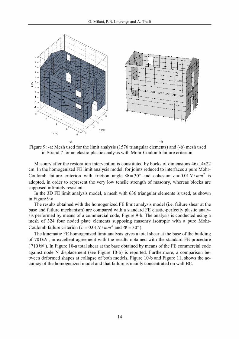
-a -b Figure 9: -a: Mesh used for the limit analysis (1576 triangular elements) and (-b) mesh used
in Strand 7 for an elastic-plastic analysis with Mohr-Coulomb failure criterion.
Masonry after the restoration intervention is constituted by bocks of dimensions 46x14x22 cm. In the homogenized FE limit analysis model, for joints reduced to interfaces a pure Mohr-Coulomb failure criterion with friction angle °=Φ 30 and cohesion 2/01.0 mmNc = is adopted, in order to represent the very low tensile strength of masonry, whereas blocks are supposed infinitely resistant.
In the 3D FE limit analysis model, a mesh with 636 triangular elements is used, as shown in Figure 9-a.
The results obtained with the homogenized FE limit analysis model (i.e. failure shear at the base and failure mechanism) are compared with a standard FE elastic-perfectly plastic analy-sis performed by means of a commercial code, Figure 9-b. The analysis is conducted using a mesh of 324 four noded plate elements supposing masonry isotropic with a pure Mohr-Coulomb failure criterion ( 2/01.0 mmNc = and °=Φ 30 ).
The kinematic FE homogenized limit analysis gives a total shear at the base of the building of kN701 , in excellent agreement with the results obtained with the standard FE procedure ( kN710 ). In Figure 10-a total shear at the base obtained by means of the FE commercial code against node N displacement (see Figure 10-b) is reported. Furthermore, a comparison be-tween deformed shapes at collapse of both models, Figure 10-b and Figure 11, shows the ac-curacy of the homogenized model and that failure is mainly concentrated on wall BC.

G. Milani, P.B. Lourenço and A. Tralli
15
-a -b
Figure 10: Via Arizzi house, standard FE elastic plastic approach. Shear at the base - node N displacement curve. -b: deformed shape at collapse.
Figure 11: Deformed shape at collapse and concentration of plastic dissipation for the entire
building, homogenization FE limit analysis approach. Finally it is worth noting that the proportionality coefficient (defined as the ratio between horizontal load at failure and vertical loads) obtained with the homogenization model at hand is approximately equal to 0.36, in good agreement with that found in [17] (0.38).
5 CONCLUSIONS In the present paper a kinematic FE limit analysis approach for the 3D analysis of masonry buildings subjected to horizontal actions has been presented. Both in- and out-of-plane fail-ures are taken into account in the evaluation of the total internal power dissipated.

G. Milani, P.B. Lourenço and A. Tralli
16
Meaningful examples have been treated with the model at hand and comparisons with stan-dard incremental elastic-plastic procedures have been reported, in order to test the reliability of the homogenized model developed in terms of both collapse mechanism and ultimate shear at the base.
ACKNOWLEDGMENTS A.Tralli and G.Milani gratefully acknowledge the support of the research project MIUR COFIN 2005 – Resistenza e degrado di interfacce in materiali e sistemi strutturali. Coordina-tor: Prof. A. Corigliano.
A.Tralli and G.Milani gratefully acknowledge Ing. G.Andrighetti (Head Engineer) and Ing. G.Galvan of the “Provincia di Ferrara”.
REFERENCES [1] L. Ramos, P.B. Lourenço, Modeling and vulnerability of historical city centers in seis-
mic areas: a case study in Lisbon. Engineering Structures, 26, 1295-1310, 2004.
[2] A. Giuffrè (editor), Safety and conservation of historical centers: the Ortigia case. Editore Laterza, Roma - Bari, 1993 [in Italian].
[3] G. Milani, P.B. Lourenço, A. Tralli, Homogenised limit analysis of masonry walls. Part I: failure surfaces. Comp. Struct., 84, 166-180, 2006.
[4] G. Milani, P.B. Lourenço, A. Tralli, A homogenization approach for the limit analysis of out-of-plane loaded masonry walls. Accepted for publication in ASCE Journal of Structural Engineering, 2006.
[5] O.P.C.M. 3274, 20/03/2003, Primi elementi in materia di criteri generali per la classificazione sismica del territorio nazionale e di normative tecniche per le costruzioni in zona sismica [in Italian].
[6] O.P.C.M. 3431/05 09/05/2005, Ulteriori modifiche ed integrazioni all'OPCM 3274/03 [in Italian].
[7] P.B. Lourenço, R. de Borst, J.G. Rots, A plane stress softening plasticity model for orthotropic materials. International Journal for Numerical Methods in Engineering, 40, 4033-4057, 1997.
[8] A. Zucchini, P.B. Lourenço, A micro-mechanical model for the homogenisation of ma-sonry. International Journal of Solids and Structures, 39, 3233-3255, 2002.
[9] P. Suquet, Analyse limite et homogeneisation. Comptes Rendus de l'Academie des Sciences - Series IIB – Mechanics, 296, 1355-1358, 1983.
[10] G. Milani, P.B. Lourenço, A. Tralli, Homogenised limit analysis of masonry walls. Part II: structural examples. Comp. Struct., 84, 181-195, 2006.
[11] R. De Benedictis, G. de Felice, A. Giuffrè, Safety and Conservation of Historical Cen-tres: The Ortigia Case, Chapter 9 Seismic Retrofit of a Building. 189–217. A. Giuffrè, Editori Laterza, 1991.

G. Milani, P.B. Lourenço and A. Tralli
17
[12] S.W. Sloan, P.W. Kleeman, Upper bound limit analysis using discontinuous velocity fields. Computer Methods in Applied Mechanics and Engineering, 127 (1-4), 293-314, 1995.
[13] J. Munro, A.M.A. Da Fonseca, Yield-line method by finite elements and linear pro-gramming. J. Struct. Eng. ASCE, 56B, 37-44, 1978.
[14] A.A. Cannarozzi, M. Capurso, F. Laudiero, An iterative procedure for collapse analysis of reinforced concrete plates. Computer Methods in Applied Mechanics and Engineer-ing, 16, 47-68, 1978.
[15] S.W. Sloan, A steepest edge active set algorithm for solving sparse linear programming problems. International Journal Numerical Methods Engineering, 12, 61-67, 1988.
[16] P.C. Olsen, Rigid-plastic finite element analysis of steel plates, structural girders and connections. Computer Methods in Applied Mechanics and Engineering, 191, 761-781, 2001.
[17] A. Orduna, Seismic assessment of ancient masonry structures by rigid blocks limit analysis. PhD Thesis 2003. University of Minho, Portugal. Available at www.civil.uminho.pt/masonry.
[18] P.B. Lourenço, Computational strategies for masonry structures. PhD Thesis 1996. Delft University of Technology, the Netherlands. Available at www.civil.uminho.pt/masonry.
[19] P.B. Lourenço, J. Rots, A multi-surface interface model for the analysis of masonry structures. Journal of Engineering Mechanics ASCE, 123 (7), 660-668, 1997.
[20] D.M. 16/01/1996 (G.U. 5-2-1996, N. 29), Norme tecniche relative ai “Criteri generali per la verifica di sicurezza delle costruzioni, e dei carichi e sovraccarichi” [in Italian].
[21] A. Brencich, L. Gambarotta, S. Lagomarsino, Catania Project: Research on the seismic response of two masonry buildings. Chapter 6: Analysis of a masonry building in Via Martoglio. University of Genoa. CNR Gruppo Nazionale per la Difesa dei Terremoti, 107-151, 2000 [in Italian].
[22] G. Magenes, C. Braggio, Catania Project: Research on the seismic response of two ma-sonry buildings. Chapter 7: Analysis of a masonry building in Via Martoglio. Univer-sity of Pavia (in Italian). CNR Gruppo Nazionale per la Difesa dei Terremoti, 153-190, 2000.