3d fatigue fracture modeling by isogeometric boundary
TRANSCRIPT

M A M
Institute of Mechanics
& Advanced Materials I
3D fatigue fracture modeling by isogeometric boundary element methods
Xuan Peng, Elena Atroshchenko, Pierre Kerfriden, Stephane Bordas
Cardiff University, UK
April 2016
ACME 2016

2
Outline
•Motivation
•IGABEM formulation for crack modeling
•Surface breaking cracks and trimmed NURBS
•Embedded cracks
•Conclusion
3
Motivation
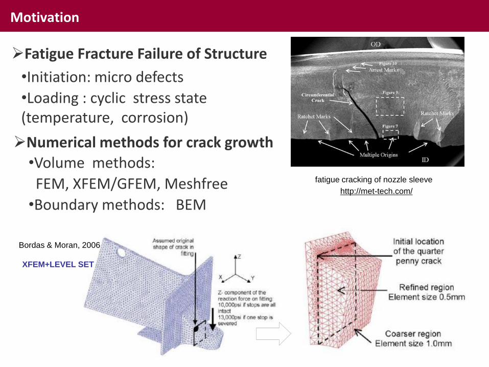
http://met-tech.com/
fatigue cracking of nozzle sleeve
Fatigue Fracture Failure of Structure
•Initiation: micro defects
•Loading : cyclic stress state (temperature, corrosion)
Numerical methods for crack growth
•Volume methods:
FEM, XFEM/GFEM, Meshfree
•Boundary methods: BEM
Bordas & Moran, 2006
XFEM+LEVEL SET

4
Motivation
Challenges in volume-based methods
Efficiency & Accuracy
XFEM
IGABEM
crack
crack
calculation
stress analysis
mesh Remeshing (FEM)
Local mesh refinement
IGA
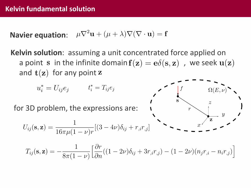
Kelvin fundamental solution
Navier equation:
Kelvin solution: assuming a unit concentrated force applied on a point in the infinite domain , we seek and for any point
for 3D problem, the expressions are:

Let source point “s” approach to the boundary
Boundary integral equation: direct method
Betti’s theorem
State (1) : auxiliary state, using Kelvin solution
State (2): real state, neglecting body force
Take derivative w.r.t. “s”
-could be used to
crack problem, dual equations
singular matrix introduced by

7
Boundary integral equations (BIEs) and crack modeling
•Collocation: Greville Abscissae
•Displacement BIE
•Traction BIE
•NURBS approximation

8
Singular integration
•Singularity subtraction technique (SST)

9
Singular integration
•Conformal mapping for SST
•Rong et al 2014, EAWBE

10
Evaluation of stress intensity factors (SIFs)
•Virtual crack closure integrals (VCCI)
•M integral

11
Penny-shaped crack under remote tension (embedded crack)

12
Penny crack under remote tension (embedded crack)

13
Penny crack under remote tension (embedded crack)

14
Penny-shaped crack under remote tension

15

16
NURBS-represented crack growth algorithm
•Fatigue fracture: Paris law

17
Numerical example of Mode-I penny crack growth (first 10 steps)

18
Numerical example of inclined elliptical crack growth (first 10 steps)
19
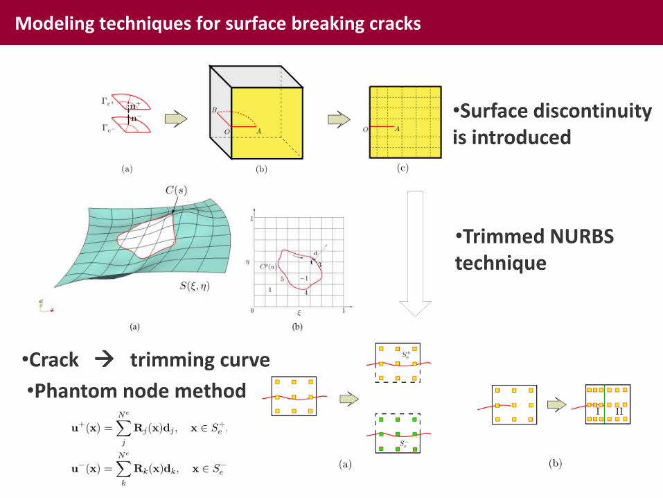
Modeling techniques for surface breaking cracks
•Surface discontinuity is introduced
•Crack trimming curve
•Trimmed NURBS technique
•Phantom node method
For surface breaking cracks, discontinuity is introduced along the body boundary. Crack initiation and propagation is difficult due to highly smoothness in basis functions
Crack can be considered as trimming curve. Then the problem is converted into trimmed NURBS modeling

20
Integration and collocation for trimmed NURBS
•Beer et al 2015, CMAME

21
Convergence study for a cube with cylindrical cutout

22
Example of surface breaking cracks: edge crack under uniform tension

23
Conclusions & Future work
•T-spline for local refinement
•Acceleration algorithm
•Dual BIEs are used for NURBS-represented fracture modeling
•Improved numerical singular integration scheme
•Approaches for SIFs evaluation
•Fatigue crack growth algorithm
•IGABEM for trimmed NURBS and surface crack modeling
•Improve the integration and collocation schemes for trimmed NURBS

24
Many thanks for YOUR attention
The financial support by FP7-ITN under grant No. 289361 "Integrating Numerical Simulation and Geometric Design Technology” is gratefully acknowledged