3d cad modeling basic mechanical components #1
TRANSCRIPT

8/8/2019 3D CAD Modeling Basic Mechanical Components #1
http://slidepdf.com/reader/full/3d-cad-modeling-basic-mechanical-components-1 1/14
http://www.instructables.com/id/3D-CAD---Modeling-Basic-Mechanical-Components-%231--/
Home Sign Up! Browse Community Submit All Art Craft Food Games Green Home Kids Life Music Offbeat Outdoors Pets Photo Ride Science Tech
3D CAD - Modeling Basic Mechanical Components #1 - Tie-Wrap Clipby cad_crew on September 12, 2006
Table of Contents
License: Attribution Non-commercial Share Alike (by-nc-sa) .............................................................................
Intro: 3D CAD - Modeling Basic Mechanical Components #1 - Tie-Wrap Clip ................................................................
step 1: 3D CAD - Tie Wrap Clip - Open default-mm file & edit Properties ....................................................................
step 2: 3D CAD - Save file with new name, and Start Sketching ..........................................................................
step 3: 3D CAD - Center the Rectangle Symmetrically .................................................................................
step 4: 3D CAD - Add Width & Height Dimensions, re-save. .............................................................................
step 5: 3D CAD - Select the Sketch, and Apply Extrude Boss ............................................................................
step 6: 3D CAD - Sketch the Rough Shape for a Cut ..................................................................................
step 7: 3D CAD - Extrude Cut the Rough Shape ......................................................................................
step 8: 3D CAD - Set fixed reference line-1 (Edit the Sketch) ............................................................................
step 9: 3D CAD - Constrain Top Lines Collinear ......................................................................................
step 10: 3D CAD - Dimension Top offsets, Left & Right. ................................................................................
step 11: 3D CAD - Dimension Bottom Left & Right offsets. ..............................................................................
step 12: 3D CAD - Dimension Bottom Line offset. .....................................................................................
step 13: 3D CAD - Exit Sketch, Update Extrude Cut, Re-Save. ...........................................................................
step 14: 3D CAD - Create Circle for Hole. ...........................................................................................
step 15: 3D CAD - Use Circle to Create Hole. ........................................................................................
step 16: 3D CAD - Create Circle, & Extrude Cut for Shoulder. ............................................................................
step 17: 3D CAD - Cut first End. .................................................................................................. 1
step 18: 3D CAD - Mirror the first Cut to Create the Second End. ......................................................................... 1
step 19: 3D CAD - Create the Sketch for the Cut Through Portion. ........................................................................ 1
step 20: 3D CAD - Trimming the Projected Lines & Cutting Through. ...................................................................... 1
step 21: 3D CAD - Add Fillets .................................................................................................... 1
step 22: 3D CAD - Add Part Color & Save .......................................................................................... 1
step 23: Congratulations!! You did it! .............................................................................................. 1
Related Instructables ........................................................................................................... 1
Advertisements ............................................................................................................... 1
Comments ................................................................................................................... 1

8/8/2019 3D CAD Modeling Basic Mechanical Components #1
http://slidepdf.com/reader/full/3d-cad-modeling-basic-mechanical-components-1 2/14
http://www.instructables.com/id/3D-CAD---Modeling-Basic-Mechanical-Components-%231--/
License: Attribution Non-commercial Share Alike (by-nc-sa)
Intro: 3D CAD - Modeling Basic Mechanical Components #1 - Tie-Wrap ClipThis tutorial is abouit modeling simple and basic mechanical components with 3D Mechanical CAD programs, Specifically one called Alibre Xpress, a freely available MCAD prgram available from Alibre, Inc. at www.alibre.com/xpress
· You will learn to use a basic created default file as a starting point.· You will quickly edit the basic material component, apply, and save the file.· You will get further experience with Sketching & Constraints.· You use 3D Mirror features, and add 3D Fillets.
It is assumed you already have Al ibre Design Xpress or other versions of Alibre Design installed, and that you have a working knowledge of windows and keyboardshortcuts, and have completed the Standard Workspace Setup & Creation tutorial.
step 1:3D CAD - Tie Wrap Clip - Open default-mm file & edit Properties-Start/Launch Alibre Design Xpress.From the Alibre Design Xpress - Home Window - Click File, select the file in the drop down menu called 'default-mm' as created in the Standart Workspace Setup &Creation tutorial .
If it is not in the file l ist, select Open (Shortcut Ctrl+O), and find the file where you saved it (folder ‘Alibre’ > tutorials).
From the default-mm part file menu, Click File, select Properties, Click.From the Properties Dialog, Select the Materials tab, and scroll the material selection down toselect Nylon 6/10, click. Click Apply, Click Close to close the properties dialog
step 2:3D CAD - Save file with new name, and Start Sketching-In the part workspace, now save the file as ‘tie-wrap-clip’ in your Alibre tutorials folder.
Now Click XY-Plane in the Design Explorer, and start Sketching with a 2 Corner Rectangle.
Sketch a small Rectangle around the Origin (with the origin inside of the rectangle).
From the View Menu, select References, All, Click it.

8/8/2019 3D CAD Modeling Basic Mechanical Components #1
http://slidepdf.com/reader/full/3d-cad-modeling-basic-mechanical-components-1 3/14
http://www.instructables.com/id/3D-CAD---Modeling-Basic-Mechanical-Components-%231--/
step 3:3D CAD - Center the Rectangle Symmetrically-From the Sketching Toolbar, Click the Constraints Options Flyout, Click Symmetric Constraint.Note the hint in the Status Line:“ Select the axis of symmetry for the symmetric constraint. Press ESC to Cancel ”
Click the Vertical Axis as the axis of symmetry for the Symmetric ConstraintA reference line is created that is co-located with the vertical axis.
Now note the changed hint in the Status Line:“ Select the FIRST figure or point for the symmetric constraint. Press ESC to Cancel ”
Select the Left side of the Rectangle as the first figure, noting the status line:“ Select the SECOND line for the symmetric constraint. Press ESC to Cancel ”
Then click the right side to complete the Symmetrical Constraint about the Vertical Axis.
Proceed with selecting the Horizontal Axis, and the upper and lower lines on the Rectangle to make itsymmetric about the two Axis.
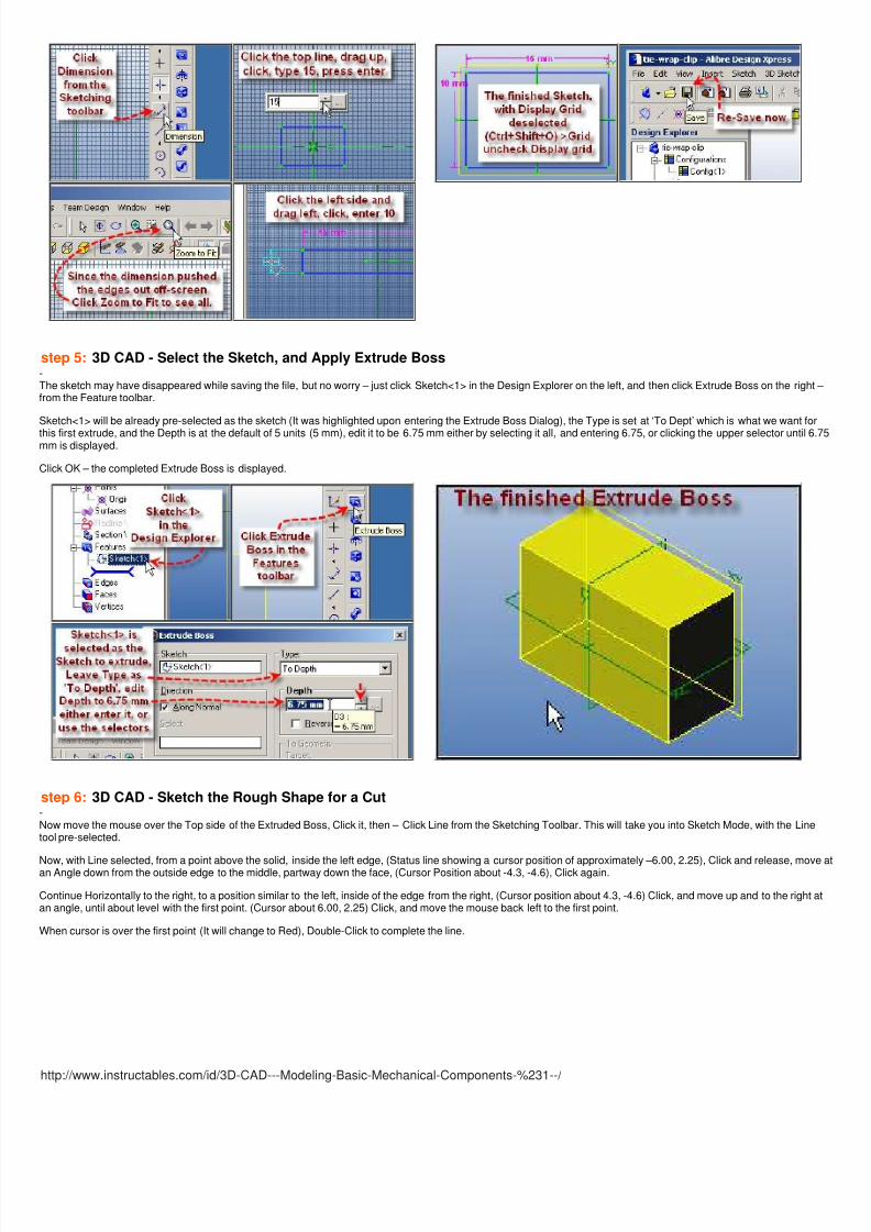
step 4:3D CAD - Add Width & Height Dimensions, re-save.-Now Select Dimension from the Sketching Toolbar,
Click the upper line, drag up to place the dimension, click, enter a value of 15,
Since the width of the edges is now pushed off screen, left and right, click ‘Zoom to Fit’ to bring it all back, and if necessary, roll the mouse wheel back a few clicks or alittle bit to size the sketch.
Click the left or right side line and drag to the outside of the rectangle, click, and enter a value of 10.You can now see the finished sketch with dimensions better by deselecting display grid from the Options dialog. (Ctrl+Shift+O > Grid > deselect ‘Display grid’).
Now – re-save the file so that nothing created to this point gets lost if something should happen.
This is a good practice, and a good reason to save a workspace with the project name early.
8/8/2019 3D CAD Modeling Basic Mechanical Components #1
http://slidepdf.com/reader/full/3d-cad-modeling-basic-mechanical-components-1 4/14

8/8/2019 3D CAD Modeling Basic Mechanical Components #1
http://slidepdf.com/reader/full/3d-cad-modeling-basic-mechanical-components-1 5/14
http://www.instructables.com/id/3D-CAD---Modeling-Basic-Mechanical-Components-%231--/
step 7:3D CAD - Extrude Cut the Rough Shape-Next, click the Extrude Cut icon from the Part Modeling toolbar.Click the ‘Type’ selector triangle, and select ‘Through ALL’ from the drop-down menu.
You will see the sketch displayed at the dear and far sides of the Boss.
Now Click OK to complete the rough cut.
step 8:3D CAD - Set fixed reference line-1 (Edit the Sketch)-Mouse over Sketch<2> in the Design Explorer, Right-Click, from the menu, select ‘Edit’,
Click to edit that sketch. Now Click ‘Project to Sketch’ from the bottom of the Sketching toolbar.
Click Create Reference figure, and Maintain association, click in Entities, and click the Top edge.
Now Click OK, and to make the top edge line just created more visible, click it to select it.
This line will be used to set alignment of the sketch Top line previously created.

8/8/2019 3D CAD Modeling Basic Mechanical Components #1
http://slidepdf.com/reader/full/3d-cad-modeling-basic-mechanical-components-1 6/14
http://www.instructables.com/id/3D-CAD---Modeling-Basic-Mechanical-Components-%231--/
step 9:3D CAD - Constrain Top Lines Collinear-Mouse over the triangle (Options) below the Constraints Icon in the Sketching toolbar to activate the Constraints flyout menu, then select the Collinear Constraint, andclick it.
With Collinear constraint selected, click the Sketch Top line, then the newly created fixed reference line.
The Sketch top line will move to the fixed reference line to become collinear with it.
8/8/2019 3D CAD Modeling Basic Mechanical Components #1
http://slidepdf.com/reader/full/3d-cad-modeling-basic-mechanical-components-1 7/14
http://www.instructables.com/id/3D-CAD---Modeling-Basic-Mechanical-Components-%231--/
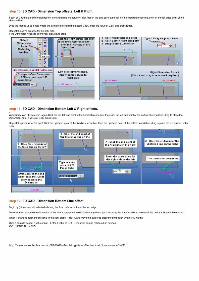
step 10:3D CAD - Dimension Top offsets, Left & Right.-Begin by Clicking the Dimension Icon in the Sketching toolbar, then click first on the end point at the left on the fixed reference line, then on the left edge point of thesketched line.
Drag the mouse up to locate where the Dimension should be placed, Click, enter the value of 2.55, and press Enter.
Repeat the same process for the right side.If the Dimension needs to be moved, click it and drag.
step 11:3D CAD - Dimension Bottom Left & Right offsets.-With Dimension Still selected, again Click the top left end point of the fixed reference line, then click the left end point of the bottom sketched line, drag to place theDimension, enter a value of 3.85, press Enter.
Repeat the process for the right: Click the right end point of the fixed reference line, then the right end point of the bottom sketch line, drag to place the dimension, ent3.85.
step 12:3D CAD - Dimension Bottom Line offset.-Begin by (dimension still selected) clicking the fixed reference line at the top edge.
Dimension will assume the dimension of this line is requested, so don’t click anywhere yet – just drag the dimension box down until it is over the bottom Sketch line.
When it changes color, the cursor is in the right place – click it, and move the cursor to place the dimension where you want it.
Click it again to accept a value input – Enter a value of 2.95. Dimension can be relocated as needed.DOF Remaining = 0 now.

8/8/2019 3D CAD Modeling Basic Mechanical Components #1
http://slidepdf.com/reader/full/3d-cad-modeling-basic-mechanical-components-1 8/14
http://www.instructables.com/id/3D-CAD---Modeling-Basic-Mechanical-Components-%231--/
step 13:3D CAD - Exit Sketch, Update Extrude Cut, Re-Save.-To exit the sketch either Click the toggle of ‘Activate 2D Sketch’ or Click ‘Select’ from the View toolbar.
The updated Extrude Cut will be displayed.
Enter Properties once again (Alt+Enter), to edit the Description under the General tab.
Change the Description from: “Initial Millimeter default file” to “Tie-Wrap-Clip”. Click Apply, Close.
Click the ‘Save’ icon to re-save and update the file.
step 14:3D CAD - Create Circle for Hole.-After Saving, Click ‘Orient to Isometric’ in the View toolbar. Click the Bottom (Left angled face) and then Click ‘Circle’ from the Sketching toolbar to enter Sketch Modewith Circle selected.
Move the Cursor over the Origin, when it changes to red, Click, and drag out to about 4 mm. Click.
Select Dimension again from the Sketching toolbar, and dimension the circle to the side with a value of 3.65 mm.
Note the Degrees of Freedom (DOF Remaining) = 0, indicating it’s fully constrained.

8/8/2019 3D CAD Modeling Basic Mechanical Components #1
http://slidepdf.com/reader/full/3d-cad-modeling-basic-mechanical-components-1 9/14
http://www.instructables.com/id/3D-CAD---Modeling-Basic-Mechanical-Components-%231--/
step 15:3D CAD - Use Circle to Create Hole.-The Circle is now ready to use to create the central hole.Click Extrude Cut from the Part Modeling toolbar.
Select ‘Type’ = ‘To Next’, and if required select ‘Reverse’ to cut the correct direction.
Click ‘OK’, or press Enter to complete the Extrude Cut.
Now Click Rotate from the View toolbar, and while holding down the left mouse button, drag to the right or left to change the view to see the opposing face.
Click Select from the same toolbar. Click the Inner Flat Face, then Click Circle Icon.
step 16:3D CAD - Create Circle, & Extrude Cut for Shoulder.-The last step took you into Sketch Mode again, now Click the Cursor beside but not on the Origin, and drag out a circle larger than the hole, similar to that shown.
Click the Constraints Option selector to activate the Constraints Flyout Menu, then Click Concentric Constraint, Click the edge of the hole, and then click the Circle toconstraint it Concentric to the hole.
Again click Extrude Cut, but set it Type ‘To Depth’, Depth of 1.85, Select Reverse,and Click OK to complete the Cut.

8/8/2019 3D CAD Modeling Basic Mechanical Components #1
http://slidepdf.com/reader/full/3d-cad-modeling-basic-mechanical-components-1 10/14
http://www.instructables.com/id/3D-CAD---Modeling-Basic-Mechanical-Components-%231--/
step 17:3D CAD - Cut first End.-To create the first End cut, Click the one end face, then Click Rectangle by Two Corners, outside of the bottom (the right in sketch mode), click to begin above the cenaxis, release and drag down & to the left, short of the top, and across the center axis, then click again to place the Rectangle.
Select Dimension from the Sketching toolbar, and set the dimension of the line at the left side at 5.4 mm.
Then click this line again, and Click the left edge, place and dimension this at 1.4 mm.Proceed with Extrude cut, Type = To Depth, Depth = 2.9 mm, reverse is selected.
Click OK to complete the cut.
step 18:3D CAD - Mirror the first Cut to Create the Second End.-Once the first cut is completed on one end, use Mirror to duplicate it at the other end.
Select Feature in the main menu, and select Mirror from the drop down. In the Mirror Dialog, click the white area below ‘Features to mirror:’, then click Extrusion<5> in
the Design Explorer at the left side of the workspace.
Now Click in the white space beside ‘Mirror plane:’ – and Click the YZ Plane.
Click OK to complete the Mirror.

8/8/2019 3D CAD Modeling Basic Mechanical Components #1
http://slidepdf.com/reader/full/3d-cad-modeling-basic-mechanical-components-1 11/14
http://www.instructables.com/id/3D-CAD---Modeling-Basic-Mechanical-Components-%231--/
step 19:3D CAD - Create the Sketch for the Cut Through Portion.-Click the Save icon to Re-update the file.
Rotate the part to show facing you the yellow highlighted portion, inside face.
Click Select from the Sketching toolbar.
You enter Sketch Mode on this face as a plane.
Right Click in the toolbars area, and confirm the Visibility toolbar is checked.
Click the Visibility Options selection Triangle, and click Wireframe.
Click the workspace off the model, Click project to Sketch, and select these Entities to Project:Edge 44, Edge 4, Edge 6, Edge 10.
step 20:3D CAD - Trimming the Projected Lines & Cutting Through.-Select Trim Figure from the Sketching toolbar, and trim away the outside portion of the lines.
Re-select Shaded now instead of Wireframe. The created lines are now easily visible, and can be used to create the extrude cut for the tie-wrap pass through portion the clip.
Click Extrude Cut, Select Type – Through All, and Click OK.
If you get error message:"Error: Self intersecting lines", click OK.Typically errors like this are from overlapping lines.
Edit the sketch, and select each line, click Delete, unless you find you deleted the only line. If that happened, Click Undo (Ctrl+Z). Continue to the next line, delete aga
Before leaving Sketch mode this time – use the Sketch Analysis tool, from the Sketch Menu.
If you find errors remaining that can’t be healed (the heal button is greyed out), (like overlapping lines) then just select them and delete them.

8/8/2019 3D CAD Modeling Basic Mechanical Components #1
http://slidepdf.com/reader/full/3d-cad-modeling-basic-mechanical-components-1 12/14
http://www.instructables.com/id/3D-CAD---Modeling-Basic-Mechanical-Components-%231--/
Then exit sketch mode by toggling the ‘Activate 2D Sketch’ icon (click it!).
step 21:3D CAD - Add Fillets-3D Fillets can now be added to the sides of the tie-wrap clip where the tie-wrap passes through.
Select Fillet from the Part Modeling toolbar, Confirm Constant Radius, unselect Tangent Propagate, set Radius for a value of 1.15, and then click on the inside edgesbeside the last extrude cut, and the outside edges beside them.
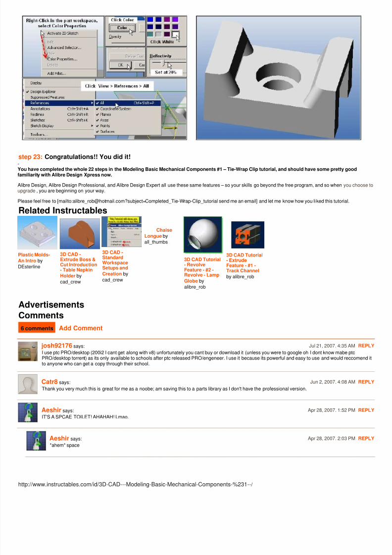
step 22:3D CAD - Add Part Color & Save-So – just add color, clean up the view by deselecting all references, and do a final save.
8/8/2019 3D CAD Modeling Basic Mechanical Components #1
http://slidepdf.com/reader/full/3d-cad-modeling-basic-mechanical-components-1 13/14
http://www.instructables.com/id/3D-CAD---Modeling-Basic-Mechanical-Components-%231--/
step 23:Congratulations!! You did it!-You have completed the whole 22 steps in the Modeling Basic Mechanical Components #1 – Tie-Wrap Clip tutorial, and should have some pretty goodfamiliarity with Alibre Design Xpress now.
Alibre Design, Alibre Design Professional, and Alibre Design Expert all use these same features – so your skills go beyond the free program, and so when you chooseupgrade , you are beginning on your way.
Please feel free to [mailto:[email protected]?subject=Completed_Tie-Wrap-Clip_tutorial send me an email] and let me know how you liked this tutorial.
Related Instructables
Plastic Molds-
An Intro by
DEsterline
3D CAD -Extrude Boss &Cut Introduction- Table Napkin
Holder by
cad_crew
3D CAD -StandardWorkspaceSetups and
Creation by
cad_crew
Chaise
Longue by
all_thumbs
3D CAD Tutorial- RevolveFeature - #2 -Revolve - Lamp
Globe by
alibre_rob
3D CAD Tutorial- ExtrudeFeature - #1 -Track Channel
by alibre_rob
Advertisements
Comments
6 comments Add Comment
josh92176 says: Jul 21, 2007. 4:35 AM REP
I use ptc PRO/desktop (200i2 I cant get along with v8) unfortunately you cant buy or download it (unless you were to google oh I dont know mabe ptcPRO/desktop torrent) as its only available to schools after ptc released PRO/engeneer. I use it because its powerful and easy to use and would reccomendto anyone who can get a copy through their school.
Catr8 says: Jun 2, 2007. 4:08 AM REP
Thank you very much this is great for me as a noobe; am saving this to a parts library as I don't have the professional version.
Aeshir says: Apr 28, 2007. 1:52 PM REP
IT'S A SPCAE TOILET! AHAHAH! Lmao.
Aeshir says: Apr 28, 2007. 2:03 PM REP
*ahem* space

8/8/2019 3D CAD Modeling Basic Mechanical Components #1
http://slidepdf.com/reader/full/3d-cad-modeling-basic-mechanical-components-1 14/14
engrmurad says: Apr 9, 2007. 3:11 PM REP
mechanical design I have also some works on mechanical design for my project.this project is actually about assembly and drawing developmentfunctionality including physical dynamics, surfacing, large assembly performance enhancing modes, routing and powerful drawing creation capabilities.I nethis functionality.Would your software provide those things?
stienman says: Sep 13, 2006. 2:41 PM REP
Thanks for the tutorials. I want to start doing this sort of thing, but no time at the moment. Looks like a lot of work to make a tutorial, though, and I appreciait.