3d bunch-by-bunch feedback system at anka to … · at anka to increase storable beam current (3d...
TRANSCRIPT

3D Bunch-By-Bunch feedback systemat ANKA to increase storable beam
current(3D Bunch-By-Bunch Feedback System in
ANKA um speicherbare Strahlstromstärke zusteigern)
Master’s Thesisby
Núria Egidos Plaja
born in 08.07.1992 in Barcelona, Spain
Institut für Physik
Reviewer: Prof. Dr. Anke-Susanne Müller (KIT – ANKA)Second Reviewer: Prof. Dr. Francesc Guinjoan (UPC)Advisor: Prof. Dr. Anke-Susanne Müller (KIT – ANKA)Second Advisor: Prof. Dr. Weber (KIT – ANKA)
Project frame: 08.02.2016 – 15.07.2016
Karlsruhe Institute of Technology – Polytechnic University of Catalonia www.kit.edu


Declaration of original work
I confirm that I have written this work independently and that no other than the specifiedsources and supports have been used, either for edition or contents, and that the Statuteof KIT of 17.05.2010 to ensure good scientific practice in the applicable areas has beenrespected.
Karlsruhe, 15.07.2016,Núria Egidos Plaja
Distribution copy approved by
Karlsruhe, 15.07.2016,Prof. Dr. Anke-Susanne Müller (KIT – ANKA)


Abstract
In the ANKA storage ring, a digital state-of-the-art Bunch-by-Bunch (BBB) feedback systemprovides damping of Coupled-Bunch-Instabilities (CBI) in order to increase the maximumstorable beam current and lifetime. Performance of this feedback strongly depends onthe phase advance in the digital Finite Impulse Response (FIR) filter. Especially duringenergy ramping, retuning of FIR filter parameters is required as the electron beam’s tunevaries with changing machine optics. With this purpose, an algorithm for the automatictuning of the filter is proposed. Tests performed during several energy rampings showan improvement in rejection of instabilities, which means the robustness of the feedbacksystem against changes in machine settings is enhanced. Beam lifetime is also a criticalparameter to evaluate performance of the storage ring. It is related to the bunch length inthe longitudinal axis, which must be not too short to reduce beamloss. So as to increasethe bunch length and thus enhance beam lifetime, beam modulation at the quadrupoleresonance is applied in the longitudinal axis. An algorithm for the automatic configurationof this modulation has been implemented and tested during injection. Results show asignificant enhancement of beam lifetime, but reproducibility of the obtained values will bediscussed.


Acknowledgements
I would like to thank the entire THz group in the ANKA storage ring for their support andguidance, for encouraging the participation in the group meetings and for the very niceconversations in the coffee break. Special thanks to my supervisors Prof. Dr. Anke-SusanneMüller and Prof. Dr. Marc Weber for their guidance regarding physics, but also for the keylearnings about research dynamics and procedures. My gratitude to Dr. Manuel Schedler,with whom I had the chance to work closer, for his readiness to help, constant availabilityand flexibility. My most sincere gratitude for your patience and for helping me to improvemy German.Many thanks in addition to Dr. Erik Bruendermann for an indispensable introduction tothe real world of research; to Edmund Blomley and Christian Fehlinger, amongst others,for making possible the experimental part of this thesis; to Dr. Stefan Funkner, Dr.Markus Schwarz, Miriam Brosi and Florian Rämisch for their advice when preparing thepresentation and writing the thesis. Thanks in addition to Nigel Smale and Bennie Smit,for being so nice with me and giving me advice in areas I would not have expected to - Iguess they were not aware either.I must also praise the efficiency and kindness of the DB and SBB/CFF employees, thanksto whom my laptop and me crossed our paths again on a long and intensive journey formKarlsruhe to Barcelona, thus making possible that this work was finished in time.Thanks to my family and friends, for your advice, your support and for making the distancevanish every Friday evening. The smallest things make life incredibly better with such agang.


Disclaimer
Experimental results presented in this document were obtained on 20/5/2016 in ANKAstorage ring, right after a shutdown due to the replacement of a damaged component.Vacuum pressure and beam current (about a dozen of mA) were not the nominal operationconditions, which may have significantly biased the obtained values. Discussion on resultsand evaluation of performance of algorithms presented are based on obtained values, someasurements should be repeated under nominal operation conditions in order to verifyimprovements claimed here.


Contents
Abstract v
Acknowledgements vii
Disclaimer ix
1. Introduction 1
2. On characterization of a storage ring 52.1. Fundamental physics of a storage ring . . . . . . . . . . . . . . . . . . . . . 52.2. Beam dynamics of a single, charged particle . . . . . . . . . . . . . . . . . . 7
2.2.1. Effects of magnetic fields on particle motion and emission of syn-chrotron light . . . . . . . . . . . . . . . . . . . . . . . . . . . . . . . 8
2.2.2. Effects of electric fields on particle motion . . . . . . . . . . . . . . . 82.3. Beam dynamics in the multibunch scenario . . . . . . . . . . . . . . . . . . 102.4. Methods for correction of CBI to increase storable beam current . . . . . . 11
2.4.1. Frequency control of the Higher Order Modes (HOM) of the RF cavities 122.4.2. Active feedback . . . . . . . . . . . . . . . . . . . . . . . . . . . . . . 12
2.5. Methods to enhance the beam lifetime . . . . . . . . . . . . . . . . . . . . . 13
3. Bunch-by-Bunch control system 153.1. Fundamentals of feedback loops . . . . . . . . . . . . . . . . . . . . . . . . . 153.2. Feedback loop of a BBB control system . . . . . . . . . . . . . . . . . . . . 153.3. Heterodyne demodulation of the readout of the Beam Position Monitor . . 193.4. Spectra of the temporal changes of a single bunch’s positions . . . . . . . . 21
3.4.1. Synchrotron sidebands observed in the transverse spectrum in ANKA 243.4.2. Spectra of the temporal changes of a single bunch’s positions observed
in ANKA . . . . . . . . . . . . . . . . . . . . . . . . . . . . . . . . . 253.5. Generation of the control action . . . . . . . . . . . . . . . . . . . . . . . . . 26
4. Algorithm for automatic FIR filter tuning in the transverse BBB feedback 334.1. System behaviour during energy ramping in terms of fractional tune . . . . 344.2. Effects of transverse BBB control detuning due to betatron tune shift during
energy ramping . . . . . . . . . . . . . . . . . . . . . . . . . . . . . . . . . . 354.2.1. Excitation of betatron CBI . . . . . . . . . . . . . . . . . . . . . . . 374.2.2. Excitation of synchrotron sidebands in the transverse spectrum . . . 394.2.3. Asymmetry of the dip at the betatron fractional tune in the transverse
spectrum magnitude . . . . . . . . . . . . . . . . . . . . . . . . . . . 424.2.4. Partial beamloss during energy ramping . . . . . . . . . . . . . . . . 43
4.3. Algorithm for the automatic FIR filter tuning in the transverse BBB controlsystem . . . . . . . . . . . . . . . . . . . . . . . . . . . . . . . . . . . . . . . 444.3.1. Configurable parameters and criteria to dimension the digital FIR filter 45

4.3.2. Algorithm for automatic FIR filter tuning . . . . . . . . . . . . . . . 474.4. Discussion on results obtained with automatic FIR filter tuning . . . . . . . 50
4.4.1. Effect of the automatic FIR filter tuning on the damping of betatronCBI and synchrotron sidebands . . . . . . . . . . . . . . . . . . . . . 50
4.4.2. Effect of the automatic FIR filter tuning on the asymmetry of thedip at the betatron fractional tune . . . . . . . . . . . . . . . . . . . 53
4.4.3. Effect of the automatic FIR filter tuning on the partial beamlossduring energy ramping . . . . . . . . . . . . . . . . . . . . . . . . . . 54
5. Algorithm for the automatic tuning of the DAC Drive arbitrary signal generatorin the longitudinal feedback 575.1. Algorithm for the automatic tuning of the DAC Drive generator parameters
to enhance beam lifetime . . . . . . . . . . . . . . . . . . . . . . . . . . . . 595.2. Methods to evaluate the performance of the automatic DAC Drive generator
tuning algorithm and discussion on the obtained results . . . . . . . . . . . 60
6. Summary 63
Appendix 65A. Figures of ANKA storage ring . . . . . . . . . . . . . . . . . . . . . . . . . . 65B. C++ source code corresponding to algorithms presented in this thesis . . . 65C. Matlab code for processing of signals acquired from EPICS interface . . . . 65
Bibliography 67

List of Figures
2.1. Overview of the ANKA storage ring . . . . . . . . . . . . . . . . . . . . . . 6
2.2. Coordinate system to which particle motion is referred: X, Y and Z standfor horizontal, vertical and longitudinal axes respectively. Particles revolvingabout the storage ring describe oscillations in respect of the nominal trajec-tory (that of the synchronous particle) in the transverse plane (the so-calledbetatron oscillations) and in the longitudinal plane (synchrotron oscillations) 7
2.3. Electric field in the RF cavity as a function of time and its effect on longitu-dinal particle motion: synchronous particles gain an energy associated tothis field which is exactly that lost in one turn due to synchrotron radiation.Particles with higher energy arrive later, thus gaining less energy, and thereverse for particles with lower energy. Thanks to this difference, longitudinalfocusing is achieved . . . . . . . . . . . . . . . . . . . . . . . . . . . . . . . 9
3.1. Overview of a feedback system: the response of the system (feedback pickupacquired with sensors) is to be matched to a reference or set point, but thismight not be achieved due to disturbances at the input of the system. So asto counteract them, a control action is computed with a controller; and thenit is applied to the system to be stabilised (plant) by means of an actuator.This control action becomes the new input to the system, thus steering ittowards the desired performance . . . . . . . . . . . . . . . . . . . . . . . . 16
3.2. Overview of a BBB control system: the response of the system (amplitudeand phase of the oscillations of the beam around its nominal trajectory)is to be matched to a reference or set point, i.e. the stable motion in thetransverse and longitudinal planes (in the case of BBB, there is no externalreference, but the stable motion is achieved inherently). This might not beachieved due to disturbances at the input of the system (CBI). So as tocounteract them, a control action is computed with a controller; and then itis applied to the beam by means of an actuator (kicker). This control actionbecomes the new input to the system, thus steering the beam towards astable motion . . . . . . . . . . . . . . . . . . . . . . . . . . . . . . . . . . . 17
3.3. Implementation of the BBB control system in ANKA . . . . . . . . . . . . . 19
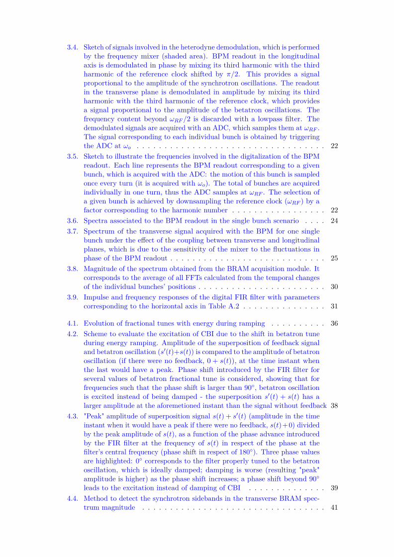
3.4. Sketch of signals involved in the heterodyne demodulation, which is performedby the frequency mixer (shaded area). BPM readout in the longitudinalaxis is demodulated in phase by mixing its third harmonic with the thirdharmonic of the reference clock shifted by π/2. This provides a signalproportional to the amplitude of the synchrotron oscillations. The readoutin the transverse plane is demodulated in amplitude by mixing its thirdharmonic with the third harmonic of the reference clock, which providesa signal proportional to the amplitude of the betatron oscillations. Thefrequency content beyond ωRF /2 is discarded with a lowpass filter. Thedemodulated signals are acquired with an ADC, which samples them at ωRF .The signal corresponding to each individual bunch is obtained by triggeringthe ADC at ωo . . . . . . . . . . . . . . . . . . . . . . . . . . . . . . . . . . 22
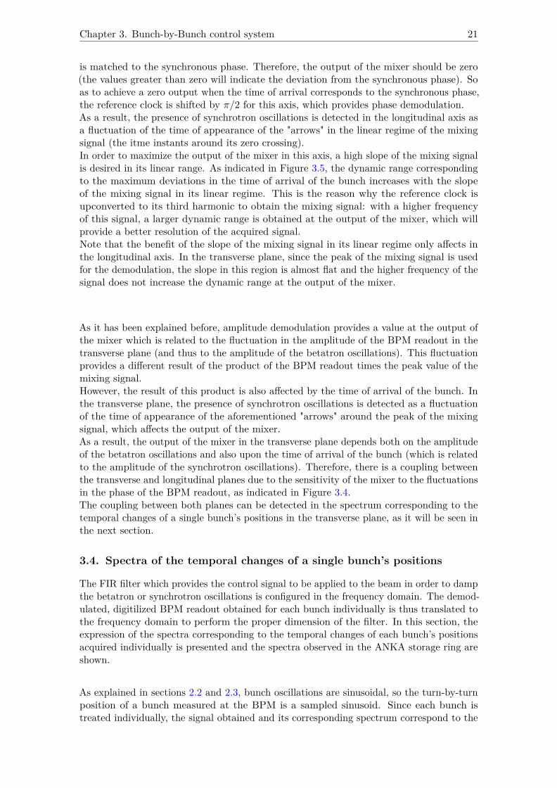
3.5. Sketch to illustrate the frequencies involved in the digitalization of the BPMreadout. Each line represents the BPM readout corresponding to a givenbunch, which is acquired with the ADC: the motion of this bunch is sampledonce every turn (it is acquired with ωo). The total of bunches are acquiredindividually in one turn, thus the ADC samples at ωRF . The selection ofa given bunch is achieved by downsampling the reference clock (ωRF ) by afactor corresponding to the harmonic number . . . . . . . . . . . . . . . . . 22
3.6. Spectra associated to the BPM readout in the single bunch scenario . . . . 243.7. Spectrum of the transverse signal acquired with the BPM for one single
bunch under the effect of the coupling between transverse and longitudinalplanes, which is due to the sensitivity of the mixer to the fluctuations inphase of the BPM readout . . . . . . . . . . . . . . . . . . . . . . . . . . . . 25
3.8. Magnitude of the spectrum obtained from the BRAM acquisition module. Itcorresponds to the average of all FFTs calculated from the temporal changesof the individual bunches’ positions . . . . . . . . . . . . . . . . . . . . . . . 30
3.9. Impulse and frequency responses of the digital FIR filter with parameterscorresponding to the horizontal axis in Table A.2 . . . . . . . . . . . . . . . 31
4.1. Evolution of fractional tunes with energy during ramping . . . . . . . . . . 364.2. Scheme to evaluate the excitation of CBI due to the shift in betatron tune
during energy ramping. Amplitude of the superposition of feedback signaland betatron oscillation (s′(t)+s(t)) is compared to the amplitude of betatronoscillation (if there were no feedback, 0 + s(t)), at the time instant whenthe last would have a peak. Phase shift introduced by the FIR filter forseveral values of betatron fractional tune is considered, showing that forfrequencies such that the phase shift is larger than 90◦, betatron oscillationis excited instead of being damped - the superposition s′(t) + s(t) has alarger amplitude at the aforemetioned instant than the signal without feedback 38
4.3. "Peak" amplitude of superposition signal s(t) + s′(t) (amplitude in the timeinstant when it would have a peak if there were no feedback, s(t)+0) dividedby the peak amplitude of s(t), as a function of the phase advance introducedby the FIR filter at the frequency of s(t) in respect of the phase at thefilter’s central frequency (phase shift in respect of 180◦). Three phase valuesare highlighted: 0◦ corresponds to the filter properly tuned to the betatronoscillation, which is ideally damped; damping is worse (resulting "peak"amplitude is higher) as the phase shift increases; a phase shift beyond 90◦leads to the excitation instead of damping of CBI . . . . . . . . . . . . . . 39
4.4. Method to detect the synchrotron sidebands in the transverse BRAM spec-trum magnitude . . . . . . . . . . . . . . . . . . . . . . . . . . . . . . . . . 41

4.5. Scheme to evaluate the excitation of synchrotron sidebands regarding thephase advance introduced by the FIR filter. Amplitude of the superpositionof feedback signal at the synchrotron sideband frequency and the sidebanditself (s′(t) + s(t)) is compared to the amplitude of the synchrotron sideband(if there were no feedback, 0 + s(t)), at the time instant when the last wouldhave a peak. Several phase advance values introduced by the FIR filterare considered, showing that for phase shifts larger than 90◦, synchrotronsidebands are excited instead of being damped: the superposition has alarger amplitude at the aforemetioned instant than the signal without feedback) 42
4.6. Method to quantify the asymmetry of the dip in the transverse spectrummagnitude in terms of its average value . . . . . . . . . . . . . . . . . . . . 44
4.7. Frequency response of the FIR filter calculated as the FFT of equation 3.10for coefficients in Table A.2. The central frequency is marked as a green spot 45
4.8. Phase shift introduced by the FIR filter (phase advance at its bandwidth inrespect of the phase at its central frequency) as a function of the number oftaps. The theoretical maximum phase shift allowed in order to avoid excitingthe synchrotron sidebands is indicated with a red, dashed line; the maximumphase shift allowed considered in the presented algorithm corresponds to thegreen, dashed line . . . . . . . . . . . . . . . . . . . . . . . . . . . . . . . . . 47
4.9. Bandwidth of the FIR filter and as a function of the number of taps. Thedistance between the synchrotron sidebands and the betatron fractionaltune, which corresponds to the synchrotron fractional tune, is indicated witha red, dashed line . . . . . . . . . . . . . . . . . . . . . . . . . . . . . . . . . 48
4.10. Steps of the algorithm for automatic FIR filter tuning which are executedperiodically during energy ramping . . . . . . . . . . . . . . . . . . . . . . . 49
4.11. Optimal number of taps as a function of the FIR central frequency (betatronfractional tune expressed in kHz) for central gain = shift gain = 1 . . . . . 51
4.12. Evolution of the magnitude of the transverse spectrum (obtained from theBRAM acquisition module) at the synchrotron sideband and at the betatronfractional tune frequencies as a function of energy during ramping. Therange of energy displayed is that in which the effect of the automatic FIRfilter tuning algorithm is most significant . . . . . . . . . . . . . . . . . . . 52
4.13. Evolution of the mean asymmetry of the dip in the betatron spectrummagnitude with energy during ramping. The range of energy displayed isthat in which the effect of the automatic tuning algorithm is most significant 54
4.14. Beam current decay during energy ramping; three rampings without auto-matic FIR filter tuning, two with automatic tuning applied in the horizontalaxis and two with automatic tuning applied in the vertical axis are shown. Inthe cases when automatic FIR filter tuning is applied, the partial beamlossand the slope of beam current decay are computed from the red, dashed line(the steep initial decay is not considered because is not related to the BBBcontrol system) . . . . . . . . . . . . . . . . . . . . . . . . . . . . . . . . . . 55
5.1. Panel of the EPICS graphic interface corresponding to the DAC Drive arbi-trary signal generator. Fields marked in red are modified by the automatictuning algorithm . . . . . . . . . . . . . . . . . . . . . . . . . . . . . . . . . 58
5.2. Algorithm for phase modulation using the DAC Drive generator in thelongitudinal BBB control system . . . . . . . . . . . . . . . . . . . . . . . . 60
5.3. Effect of the phase modulation at the quadrupole resonance of the beam onthe beam lifetime . . . . . . . . . . . . . . . . . . . . . . . . . . . . . . . . . 61

List of Tables
A.1. Compilation of parameters of the ANKA storage ring . . . . . . . . . . . . 66A.2. Predetermined FIR filter parameters for the transverse BBB feedback (hori-
zontal/vertical/longitudinal) . . . . . . . . . . . . . . . . . . . . . . . . . . . 66

1. Introduction
Particle accelerators are based on the principle that a charged particle in a potentialdifference (voltage) is accelerated across it [Tia]. They are used in a wide range of applica-tions, including scientific research, applied physics, chemistry, biology, medicine, industrialprocessing and power engineering.Some examples of industrial applications are ion implantation in the semiconductor industryor modification of surface properties of many materials. Radiation that can be generated isused to preserve food, sterilize toxic waste or polymerize plastics.In medicine, they are used for diagnosis and therapy, as well as cancer treatment withgamma rays, neutrons and heavy charged particles.Regarding power engineering, accelerators can provide the additional heating needed forplasma ignition for producing controlled thermonuclear fusion power. Research is alsocarried out in the line of incineration of long-life nuclear waste [Bar94].
Particle accelerators can be classified regarding several criteria, for instance the typeof particles which are accelerated (electrons, protons, etc.) or the shape of the accelerator(linear or circular). A synchrotron is a type of circular particle accelerator in which chargedparticles are accelerated by means of electromagnetic fields until they approach the speedof light. In this process, radiation is emitted in the form of synchrotron light.In 1947 researchers at the General Electric Research Laboratory (GERL) first observedsynchrotron radiation, which was initially considered a nuisance because it provided anenergy loss to the revolving particles. By the late 1950’s, it was found that this type ofradiation could be used for diffraction and spectroscopy. Since the 1960’s, accelerator facili-ties devoted to producing synchrotron radiation have been built all over the world [lso16]and they have become a thriving line of research in the aforementioned fields [Tia].
Two examples of synchrotrons are high energy physics machines (particle colliders), forinstance the Large Hadron Collider at CERN; and sources of synchrotron light, whichexploit the generated synchrotron light [Dia14]. ANKA Synchrotron Radiation Facility atthe Karlsruhe Institute of Technology [ANKb] is one of the second kind.Starting in 1999, ANKA is an electron storage ring which operates at a maximum en-ergy of 2.5 GeV. Its synchrotron radiation allows conducting research in the fields oflife science, environmental research, nanosciences and microtechnologies, amongst others( [ANKb]; [Her13], p.1).
Regarding its operation, the highest beam intensity is desired in order to maximise thebrightness of the generated radiation. However, due to the electromagnetic coupling thatappears among the bunches (groups of particles that compose the beam) via the resonantstructures of the machine, coherent instabilities can occur at high beam currents. In orderto increase the storable beam current, control of such unstable motion is required ( [Tey04],p.iii). With this purpose, a Bunch-By-Bunch (BBB) control system is implemented.
1

2 3D Bunch-By-Bunch feedback system at ANKA to increase storable beam current
ANKA is a multipurpose machine: it can operate at several energy levels and it cansupport a low-alpha operation mode dedicated to the production of short bunches [ANKa].It is a ramping facility: injection energy (0.505GeV) is different from the energy at whichmost experiments are performed (2.5GeV), so energy ramping is performed from the firstto the second level.These conditions pose a changing and challeging environment for the BBB control system.Its setting depend strongly on the electron beam’s eigenfrequencies, which change regardingthe conditions of operation.
This work deals with the enhancement of performance of the BBB control system in tworegimes: on the one hand, robustness of control in the horizontal and vertical axes is to beachieved during energy ramping to increase the storable beam current. On the other hand,beam lifetime is to be increased by applying a modulation at the quadrupole resonance ofthe beam in the longitudinal axis when operating at injection energy.
In chapter 2, fundamentals of operation of a storage ring are introduced, thus setting thebases for understanding the following sections. Equations of particle motion are presented,starting with the case of one single bunch stored in the accelerator and expanding it tothe multibunch scenario. In the second case, effects of the interaction of bunches withthe environment and among them (the so-called Coupled-Bunch Instabilities, CBI) arepresented. The effects of CBI and also methods to correct them are introduced.
Chapter 3 deals with one of these methods, the Bunch-By-Bunch (BBB) control system,which is implemented in the ANKA storage ring. The main purpose of this method is todamp CBI in order to increase the storable beam current. Its architecture and principlesof operation are explained, and its limitations are introduced.
Among these limitations, the BBB control system is detuned when the energy varies duringenergy ramping, which deteriorates its performance. A strategy to avoid this detuningis presented in chapter 4. The main contribution of the present work in this section isan algorithm for the automatic adjustment of the controller of the BBB system, a digitalFinite Impulse Response (FIR) filter, which enables retuning the system as the energychanges during ramping and thus enhances the performance of the control system. Othercontributions are the algorithms to detect the involved frequency components (betatrontune, synchrotron sidebands).
Another parameter which determines the performance of the storage ring is the bunchlength. A short bunch length in the longitudinal axis is required for the proper operation ofthe undulators, periodic structures of dipole magnets that stimulate the emission of highlybrilliant synchrotron radiation. However, too short a bunch length gives rise to particlecollisions (intrabeam scattering, IBS), which reduces the beam lifetime. In chapter 5, astrategy to increase the bunch length and thus enhance the beam lifetime is presented,which consists in modulating the beam at its quadrupole resonance in the longitudinalaxis. This modulation is applied by means of the longitudinal BBB control system. Themain contribution of the present work in this section is an algorithm for the automaticconfiguration of the signal generator in the BBB control system which provides the afore-mentioned modulation.

Chapter 1. Introduction 3
The algorithms for the automatic FIR filter tuning in the transverse BBB control andthe automatic tuning of the signal generator in the longitudinal BBB control have beenimplemented and tested in the ANKA storage ring. The obtained results are discussed andfurther lines of improvement are presented. These tests were performed after a shutdownforced by the replacement of a damaged component and neither the vacuum conditions northe level of beam current were the nominal ones. This might have influenced the results,which are discussed in chapters 4 and 5.
Finally, the main features of the performed work and the obtained results are compiled inchapter 6. Specific information on the parameters of the ANKA storage ring is provided inAppendix A.The algorithms which are the contributions of this thesis are provided in Appendix B forcodes implemented in C++ and Appendix C for Matlab codes.


2. On characterization of a storage ring
In order to achieve a high brightness of the generated synchrotron light, a beam intensityas high as possible is required . This gives rise to instabilities that can provoke beamloss,thus limiting the maximum storable current. So as to counteract these instabilities andincrease the storable beam current, correction techniques are implemented to enhance theaccelerator performance ( [Lon08], p.1). The present project focuses on these techniques,in particular on their application in the ANKA storage ring.This section deals with the basic principles of accelerator physics that will be used forthe implementation of the control techniques. The state of the art of these techniques ispresented and the challenges to be addressed are introduced, thus defining the motivationsfor this work.
2.1. Fundamental physics of a storage ring
The general structure of ANKA storage ring is depicted at Figure 2.1 [ANKc]. Chargedparticles (electrons in this case) are generated in the electron gun and clumped in bunchesin the microton. The total of all bunches compose the beam. Bunches are considered interms of their centre of mass for analysis purposes.Particles reach their final speed (close to the speed of light) after the microton; however,their level of energy is still lower than that required for being injected into the storage ring.Therefore, the energy of particles is incremented following a ramp profile: in the case ofANKA storage ring, energy is ramped from 0.505 GeV to 2.5 GeV in 49500 steps at anincrement rate of 180 Hz.
Once injected into the storage ring, bunches are exposed to electric and magnetic fieldsin order to shape their trajectory and generate synchrotron radiation, which is the finalpurpose of the ring. Particles remain orbiting for several hours emitting synchrotronlight, which is channeled through beamlines to the stations where the experiments takeplace [NSR10].A beam current (electrical charge passing by a current monitor per unit time, regard-ing [Wie07], p.290) as high as possible is required to maximise the brightness or intensityof the generated radiation; it decays with time with an exponential trend.Another figure to characterize a storage ring is beam lifetime, that is, the time intervalafter which the intensity of the beam has reached 1/e of its initial value. In the case ofANKA, beam lifetime is 16 hours for a 150 mA current level [ANKc].
Particle trajectory is referred to the coordinate system depicted at Figure 2.2 ( [Sch15],p.7). In this figure, the green line represents the nominal trajectory, which is described bythe so-called "synchronous particle" - a particle orbiting with the ideal trajectory, speed(close to the speed of light) and energy level.
5

6 3D Bunch-By-Bunch feedback system at ANKA to increase storable beam current
Figure 2.1.: Overview of the ANKA storage ring

Chapter 2. On characterization of a storage ring 7
Figure 2.2.: Coordinate system to which particle motion is referred: X, Y and Z standfor horizontal, vertical and longitudinal axes respectively. Particles revolving aboutthe storage ring describe oscillations in respect of the nominal trajectory (that of thesynchronous particle) in the transverse plane (the so-called betatron oscillations) and inthe longitudinal plane (synchrotron oscillations)
Deviations from the nominal trajectory can occur in the transverse plane (horizontal andvertical axes), which are called betatron oscillations; and in the longitudinal axis, theso-called synchrotron oscillations.In the coming sections, beam dynamics, which describe the aformentioned oscillations, arepresented: first, the equations to define the trajectory of a single bunch are introduced andthe effects caused by the electromagnetic fields on its motion are explained. After this,beam dynamics are expanded to the multibunch (multiple-bunches) scenario, which is thecase for ANKA.
2.2. Beam dynamics of a single, charged particle
Particles revolving about the storage ring do not describe the ideal, circular trajectoryindicated in green at Figure 2.2, but they oscillate around of it both in the transverse andlongitudinal planes. These oscillations or, in general terms, the motion of a charged particlein a storage ring can be described with the harmonic oscillator analogy by means of theHill’s equation ( [Wie07], p.250):
s(t) + 2Ds(t) + ω2s(t) = 0 (2.1)
s(t) stands for the oscillation coordinate: x for horizontal or y for vertical displacements; zfor longitudinal oscillations. D is the natural damping or radiation damping: the powerradiated by a particle in the form of synchrotron light is proportional to the fourth powerof its energy; the higher the energy, oscillations can become unstable, but also the morepower is radiated, thus compensating for the excess in energy and leading towards a stablemotion ( [Wie07], p.299).ω is the natural frequency of the oscillation, which can be expressed as:
ω = υωo (2.2)
where υ is defined as the betatron tune for oscillations in the transverse plane or synchrotrontune for the longitudinal plane. It corresponds to the number of oscillations executed by aparticle or by a bunch of particles while travelling one turn around the ring.The tune has an integer part and a fractional part, the fractional tune, which is denoted

8 3D Bunch-By-Bunch feedback system at ANKA to increase storable beam current
by Qx, y, s for the horixontal, vertical and longitudinal axes respectively. If the beam isobserved at one single point around the ring, only the fractional tune can be determined( [JYA+], p.3).ωo is the revolution frequency, that is, the rate at which each bunch completes one turnaround the ring. The bunch repetition frequency (the inverse of the time separation betweentwo bunches) is expressed as hωo, with h the harmonic number (number of RF buckets,which is the theoretical maximum number of bunches that can be stored). The particularvalues of these magnitudes in the ANKA storage ring are listed in Table A.1.
In the transverse plane, oscillations are periodic horizontal or vertical displacements fromthe nominal, centered trajectory. In the longitudinal plane, they are periodic differences oftime of arrival of the bunch with respect to that of the synchronous bunch. This meansthat the particles will see a different phase of the RF electric field which accelerates themas that phase corresponding to the synchronous particle. For this reason, longitudinaloscillations are also known as "phase oscillations".If ω >> D, an approximated solution to equation 2.1 is the following damped sinusoidaloscillation:
s(t) = ke− tτD sin(ωt+ ψ) (2.3)
where s(t) are the oscillations in the transverse plane or longitudinal axis; k is the amplitudeof those oscillations in the corresponding axis and ψ is an arbitrary phase; τD = 1/D isthe damping time and D is the damping rate. This solution shows that the oscillations ofa single bunch are damped in a natural way, converging to the nominal trajectory.
The particle trajectory and energy are determined by means of electromagnetic fields,as it will be seen next.
2.2.1. Effects of magnetic fields on particle motion and emission of syn-chrotron light
In the ANKA storage ring, magnetic fields are generated by dipole, quadrupole andsextupole magnets ( [Her13] p.10). Dipole fields bend the beam, thus steering it towards acircular trajectory; in addition, when the accelerated electrons are deflected by the magneticfield (they move on a curved path), they radiate synchrotron light [NSR10].Similar to light rays, particle beams have a tendency to spread out due to an inherentbeam divergence. To keep the particle bunch together and thus maintain the desired beamproperties, quadrupole magnets act like lenses and focus the bunch in the transverse plane( [Wie07], p.42).Finally, sextupole magnets are used to correct for chromatic errors, that is, the change offocal length (a measure of focusing strength) of quadrupole magnets when energy varies( [Wie03], p.82).In conclusion, magnetic fields enable the generation of synchrotron light and correctdeviations from the nominal trajectory in the transverse plane.
2.2.2. Effects of electric fields on particle motion
Once electrons are injected into the ring, they revolve at a constant speed and they areintended to have a constant energy too, thus describing orbits of the same radius [Tia].However, due to radiation of synchronous light, particles lose some of their energy in eachturn, and this affects the radius of the orbit they describe. This energy loss is compensatedby means of a time-varying longitudinal electric field provided by radio frequency (RF)cavities.These are resonant structures of a high quality factor (high-Q cavities). They are shaped to

Chapter 2. On characterization of a storage ring 9
Figure 2.3.: Electric field in the RF cavity as a function of time and its effect onlongitudinal particle motion: synchronous particles gain an energy associated to thisfield which is exactly that lost in one turn due to synchrotron radiation. Particles withhigher energy arrive later, thus gaining less energy, and the reverse for particles withlower energy. Thanks to this difference, longitudinal focusing is achieved
resonate at the frequency of the electric field (RF), so as to transfer the energy they receivefrom a RF power source to the electrons as they pass through the cavity, and thus restorethe energy lost during one turn. With this, the radius of their orbit is to be maintainedconstant [uWo01]. The frequency of the RF electric field is also the theoretical maximumbunch repetition frequency ωRF (500MHz in the case of ANKA, as shown in Table A.1).Energy gained by a bunch with crossing the cavity is proportional to the amplitude of thevoltage in the cavity and this, in turn, is proportional to the RF electric field strength [WBX],as illustrated with expression 2.4. In a time instant τ , the energy transferred to a particlecrossing the cavity can be expressed as:
E(τ) = eV (τ) ∝∫ τ
0ε(ωRF t)dt (2.4)
with e the electron charge; V (τ) the RF voltage in the cavity in the time instant τ ; and εthe electric field of frequency ωRF .This equation shows that energy is related to the integral of the RF electric field. Since thisis sinusoidal, energy and electric field are shifted by π/2. Therefore, the relation betweenthe particle longitudinal motion and the energy gained when crossing the cavity can beexpressed in terms of the RF electric field, taking into account this phase shift.In this line, Figure 2.3 shows the RF electric field in the cavity and the instants of arrivalof the different bunches. Synchronous bunches, those describing the nominal trajectory(their rotation is synchronous with the RF field), are depicted in blue. It can be seen thatthere are two phases of arrival in which the synchronous bunch can gain the energy lostdue to synchrotron radiation in one turn (this level of energy is indicated by the dashedhorizontal line); but only the one with descending slope of the electric field corresponds toa phase of stable equilibrium ( [San79], p.83).There is an integer number of RF periods TRF in one revolution period To: h is the harmonicnumber and it corresponds to the maximum of synchronous particles or bunches representedby its centre of mass orbiting the ring. As a consequence, h is also the maximum numberof storable bunches ( [San79], p.81).
In addition to restoring the energy lost in one turn, the RF electric field provides longitudinal

10 3D Bunch-By-Bunch feedback system at ANKA to increase storable beam current
focusing, that is, it forces that all particles tend to arrive in the instant corresponding to asynchronous particle. So is represented in Figure 2.3 and it can be understood as follows( [Hol12], p.12):
• Particles orbit at a constant speed, but the orbit radius depends on dispersion effectsthat take place in the magnets regarding particle’s energy: particles with a higherenergy are less deflected and thus describe a longer orbit, and particles with a lowerenergy are more deflected and thus follow a shorter orbit.
• In the case of the particle describing the longer orbit, it will arrive later to thecavity, and thus will see a phase of the RF field which is advanced in respect of thesynchronous phase. In turn, it will see a lower amplitude of the field or, in otherterms, it will gain a lower energy. Due to this, it will describe a shorter orbit in thefollowing turns, thus adjusting its motion to the nominal one.
• The reverse occurs for the particle describing the shorter orbit: it will arrive earlierto the cavity, it will see a higher level of the RF field and thus will gain more energythan the nominal one. This excess of energy will lead to a longer orbit, approachingthe synchronous timing in the following turns.
Beyond adjusting the longitudinal motion to the synchronous one, longitudinal focusinggroups particles around the corresponding multiple of the synchronous time, thus generatingthe bunches and defining their length.
At this point, beam dynamics for the single bunch scenario have been presented and it hasbeen seen how bunches can be steered using magnetic fields and how they are generatedand accelerated with electric fields. It has also been explained that dynamics of a singlebunch are intrinsically stable due to natural or radiation damping.However, there are multiple bunches orbiting the storage ring (a maximum of h bunches).The motion of each bunch has an effect on that of the other bunches, as presented in thenext section.
2.3. Beam dynamics in the multibunch scenario
In the multibunch scenario, dynamics of a given bunch are affected by those of the surround-ing bunches, they are coupled by an electromagnetic field. With a weak (low intensity)beam, individual bunches behave essentially like single bunches and their motion is inher-ently stable - as seen with equation 2.3, oscillations are naturally damped. But with anintense beam as that required for modern synchrotron light sources, the large number ofmoving charges leads to the generation of an additional "self-induced electromagnetic field"or "wakefield" when crossing the RF cavities ( [Lac92], p.368); or by interacting with thewalls of the vacuum chamber through which they circulate ( [Wol09a], p.45).The wakefield excited by a given bunch is sampled by the following bunches, thus couplingthe dynamics of bunches revolving about the ring ( [FCM+], p.7; [Wie07], p.674).
Similar to the single bunch case, particle motion corresponding to one bunch in themultibunch scenario can be described as a harmonic oscillator. In this case, effects ofcoupling to the other bunches adds a "driving force" or perturbation denoted by F to theequation of motion ( [Lon08],p.4):
s(t) + 2Ds(t) + ω2s(t) = F (t) (2.5)
Instabilities can occur when bunches oscillate in a coherent way (coupled-bunch oscillations),that is, when the centre of mass of the different bunches oscillate in phase and at the same

Chapter 2. On characterization of a storage ring 11
frequency either in the transverse or longitudinal planes ( [Wei03]). Under this condition,the equation of motion for one bunch in the multibunch case can be rewritten as:
s(t) + 2(D −G)s(t) + ω2s(t) = 0 (2.6)where τG = 1/G is the growth time constant and G is the growth rate. The growth time isusually in the order of hundreds or tens of turns ( [Wol09a], p.29).Analogous to equation 2.3, if ω >> (D −G), an approximated solution of equation 2.6 is:
s(t) = ke−tτ sin(ωt+ ψ) (2.7)
where s(t) are the oscillations in the transverse plane or longitudinal axis; k is the am-plitude of those oscillations in the corresponding axis and ψ is an arbitrary phase; and1 τ = 1/τD − 1/τG. If D > G, 1/τ > 0, the amplitude of the oscillation decays. G isproportional to the stored beam current: for low beam currents, damping prevails and thebeam remains stable. But for levels beyond the limit current, and also depending on otherfactors (characteristics of the wakefields, beam energy, synchrotron radiation dampingrates, etc.), it can occur that D < G, and thus oscillations grow exponentially in amplitude.In this way, coupled dynamics become unstable, which means Coupled-Bunch-Instabilities(CBI) arise ( [Wol09a], p.45).
In the multibunch scenario, each bunch oscillates at the betatron and synchrotron frequenciesand, in addition, there can be different modes of oscillation (multi-bunch modes), whichdepend on how each bunch oscillates with respect to the other bunches ( [Lon08], p.4). Forh identical bunches equally spaced around the ring, there can be up to h different modesof oscillation characterized by the phase difference between adjacent bunches:
∆ψ = m2πh
; m ∈ [0, h− 1] (2.8)
with m the mode number. CBI arise when one or more of these modes become unstable.In order to avoid that, the storage ring could operate at low currents, but this is oppositeto the purpose of the machine. In practical terms, these instabilities set the upper limitfor the storable beam current ( [Wol09a], pp.29-37). Particle beam intensity is criticallyimportant, as the brightness of the synchrotron light produced is directly proportional tothe stored electron beam current ( [Wie07], pp.671-672).If the amplitude of the bunch oscillations becomes too large, that is, beam dynamicsbecomes unstable due to coupled-bunch effects, beam quality is degradated. In the worstcase, beam can be lost; otherwise, instabilities provoke that the brightness and the spectralpurity of the synchrotron light source are reduced ( [Lon08], p.1; [Tey04], p.17).So as to avoid the uncontrolled growth of oscillation amplitude, i.e. to damp CBI toincrease the storable beam current, several control techniques are available. The nextsection reviews some of these techniques.
2.4. Methods for correction of CBI to increase storable beam currentThe need for high brightness in synchrotron light sources implies storing beam currentsas high as possible, and this gives rise to Couple-Bunch-Instabilities that can deterioratethe performance of the storage ring. These instabilities manifest as oscillations that growexponentially in amplitude in the transverse plane (related to deviations in the bunchtrajectory in respect of the nominal one) and in the longitudinal plane (related to deviationsin the bunch energy).In order to avoid the deterioration in performance caused by CBI and thus enhance thestorable beam current, correction techniques are required. This section presents some ofthese techniques: frequency control of High Order Modes (HOMs) of RF cavities; andactive feedback ( [Mos99], [Mos]).

12 3D Bunch-By-Bunch feedback system at ANKA to increase storable beam current
2.4.1. Frequency control of the Higher Order Modes (HOM) of the RFcavities
RF cavities are resonant structures, metallic empty volumes inside of which the electro-magnetic field resonates at certain given frequencies or modes that are determined by thegeometry of the cavity. The modes beyond the first are Higher Order Modes (HOMs)( [SES], pp.2-4).As it has been seen, coupled-bunch dynamics can also resonate at several modes. If someof them excite the corresponding mode of the cavity, CBI arise ( [DCH+03], p.15).So as to avoid this, RF cavities can be designed to damp the HOMs ( [Wie07], p.674); ortuned during operation (for instance, with an accurate regulation of the temperature ofoperation) so that HOMs do not match the eigenfrequencies of the beam, in order to avoidexciting those frequencies ( [KHP+03], [VKK+95]). The second is the case of ANKA.Tuning RF cavities in order to shift their resonances has mechanical limits and a slowresponse, which means it is not a suitable method if frequent and numerous adjustments ofmachine parameters (for instance, magnet aligments) are required.
2.4.2. Active feedback
Stabilization of CBI can also be achieved by means of control systems or feedback systems.These can be understood in frequency domain (Mode-by-Mode feedback) or in time domain(Bunch-by-Bunch feedback) ( [FEH+93], p.1).In the multibunch scenario, although each bunch oscillates at the betatron and synchrotrontune frequencies, there can be different modes of oscillation, called multibunch modes,which are characterized by the phase shift at which each bunch oscillates with respect tothe other bunches ( [Lon08], p.4). In a ring filled with h bunches, there are h possiblemultibunch modes; if the amplitude of the oscillation corresponding to some of them growsexponentially, it is said that those modes become unstable, i.e. CBI arise.Regarding Mode-by-Mode feedback, a single narrow-band feedback channel is providedfor every unstable of those modes. It consists of a frequency-selective filter to detectthe unstable mode, a power amplifier and a kicker which applies the control action tocounteract the unstable mode. Multiple unstable modes are treated with parallel feedbacksystems [FEH+93].With time, the number of bunches stored in synchrotron light sources and the operationcurrent have increased, and with this, the number of potential unstable multibunch modes( [Tey04], p.17). As a consequence, Mode-by-Mode control might be unfeasible.The alternative to this type of control is the time-domain approach: in Bunch-By-Bunch(BBB) control systems, each bunch is treated as an individual oscillator driven by adisturbance (which is the result of the coupled-bunch motion). The deviation from the idealdynamics, those of the synchronous particle, is detected in the transverse and longitudinalplanes, and a particular feedback signal is generated for every bunch. This feedbacksignal is applied as an electromagnetic "kick" or correction to the trajectory of each bunchindividually, which keeps its oscillations within the stability boundaries ( [Wol09a], pp.29-37).BBB control systems can be analog or digital. The second offer the advantages of moreflexibility, scalability and reproducibility, as well as the additional feature of providingaccelerator diagnostic tools ( [Lon08], pp.1,15), such as the measurement of complex HOMimpedances ( [FCM+], p.47).In ANKA, a BBB control system provided by Dimtel, Inc. [dim] is implemented. In thecoming chapters, this control system is explained in detail and some limitations of itsperformance are presented.

Chapter 2. On characterization of a storage ring 13
2.5. Methods to enhance the beam lifetime
CBI can limit the storable beam current and reduce the brightness of the synchrotron lightsource. Another figure to evaluate the performance of the storage ring is the beam lifetime,that is, the time interval after which the intensity of the beam has reached 1/e of its initialvalue. It can be obtained from the beam current using the expression:
I(t) ≈ I(0)e−t/τL (2.9)
with I(t) the current stored at time t, I(0) the initial value of the current and τL thelifetime of the beam, typically measured in hours ( [Pea12], p.19). In the case of ANKA,the beam lifetime is 16 hours for a 150 mA current level [ANKc].The highest possible beam lifetime is desired. However, it is limited by several effects;particles can be lost due to: gas scattering effects (collisions with the residual gas andions inside the vacuum system of the storage ring); intrabeam scattering (IBS, collisionsamong particles within the bunch, which is also known as Touschek effect); quantum effectsfor electron machines (it is related to the discrete or quantized nature of the emission ofsynchrotron radiation [Wal92], p.481); or as a result of CBI, amongst others ( [Bru66],chapters 26, 30 and 31). The contribution of these factors to the total beam lifetime canbe expressed as follows:
1τL
= 1τT
+ 1τq
+ 1τg
+ 1τCBI
(2.10)
with τT the Touschek lifetime, τq the quantum lifetime, τg the gas scattering lifetime andτCBI the contribution of CBI to lifetime, each of them associated to the correspondingeffect.When CBI are not the dominant effect (for instance, because they are damped by the BBBcontrol system), the limiting factors are the gas scattering effect and the Touschek effect.Residual gas scattering is the dominant effect in the case of poor vacuum pressure. As anumeric example, the poor vacuum scenario in the Cornell Electron Storage Ring would bea pressure higher than a residual gas pressure of 3.4× 10⁻⁹ Torr ( [USP01], p.17).When CBI are not limiting and the vacuum pressure is below the residual gas pressure, theTouschek effect becomes the dominant factor.
The longitudinal bunch length is defined as twice the maximum excursion of particlesfrom the bunch center in the direction of this axis ( [Wie07], p.216, p.751). The Touscheklifetime is directly proportional to the RMS bunch length in the horizontal, vertical andlongitudinal axis (σx , σy and σz respectively) and inversely proportional to the density ofparticles in the bunch, regarding the relation ( [JHKM14], p.222):
1τT∝ N
σxσyσz(2.11)
The density of particles is calculated as:
ρ = N
σxσyσz(2.12)
with N the the number of electrons per bunch and σxσyσz the RMS volume of the bunch.The effects of intrabeam scattering derived from the betatron and longitudinal motionsare projected into the longitudinal plane ( [Piw98], p.2), so an enhancement of Touscheklifetime can be achieved by acting on the longitudinal bunch length.

14 3D Bunch-By-Bunch feedback system at ANKA to increase storable beam current
On the one hand, a short bunch length in the longitudinal axis is required for the properoperation of the undulators, periodic structures of dipole magnets that stimulate theemission of highly brilliant synchrotron radiation. Usual values for longitudinal bunchlength are a few hundreds of µm (compare [KPPL08], [MTH+07], [KKJ+16]). However,the Touschek effect is more significant with short bunches, because the particle density ishigher.If the beam lifetime is limited due to the Touschek effect, expression 2.11 shows thatthe Touschek lifetime could be elongated in the same amount as the bunch length in thelongitudinal axis ( [SIMT], p.11). This is explained because with a higher bunch length,the particle density is reduced (which is shown with expression 2.12) and, with this, theprobability of collisions among particles within the bunch is also lower. That is, the IBSor the Touschek effect are reduced and thus the Touschek lifetime is enhanced ( [WN13],p.25; [Wie07], p.573).
A technique to increase the bunch length is RF voltage modulation: if such a modulationis applied at about twice the synchrotron frequency (that is, the longitudinal quadrupoleresonance), a redistribution of particles in the longitudinal plane is produced. This re-distribution can be understood as a quadrupole modulation of the longitudinal motion( [SIM+00], p.692; [SHL+98], p.1339), which leads to an increment of the longitudinalbunch length. As a consequence, a lower density of particles is achieved in the bunch core( [Ng15], p.108; [WCC+99], p.1), which reduces the probability of particle collision insidethe beam. This leads to a reduction of the Touschek effect and thus the beam lifetime isenhanced ( [WN13], p.25; [SIMT], pp.1,3,11; [KFH+10], p.2755).
RF voltage modulation is applied by means of the Low-Level-RF (LLRF) control system ofthe storage ring. It reaches the beam at the RF cavities, which have a high quality factorand thus a narrow bandwidth - a maximum bandwidth of a few dozens of kHz [SCG+] isthe usual value, so it can well be that the applied modulation exceeds the cavity bandwidth(in [SIM+00], 46.7 kHz is used as frequency for the modulation). In order to achieve thedesired effect while operating outside of the cavity bandwidth, a large RF power is required.This leads to high reflected powers which are beyond the design levels, so an RF interlockcan occur to prevent the damage of components, which would lead to beamloss.In chapter 5, an alternative solution to overcome the limitation of the narrow bandwidthof the RF cavities will be presented. This solution, which has been implemented in theANKA storage ring, is based on the BBB control system.

3. Bunch-by-Bunch control system
In practice, the beam can be stable at low currents in the multibunch scenario, as seenin section 2.3. As more current is injected into the ring, at some point a mode of thecoupled-bunch oscillations can become unstable and lead to an exponential growth of theoscillation amplitude, which will provoke beamloss.Some methods to correct CBI have been presented in section 2.4. Among these methods,the Bunch-By-Bunch (BBB) digital feedback is the alternative implemented in the ANKAstorage ring. The main goal of this control system is to add damping to the motion of parti-cles or, in other words, complement the natural damping of CBI ( [FEH+93], p.4; [Wol09a],p.29).This enables restraining the amplitude of beam oscillations within the stability boundaries,thus enhancing the beam quality and lifetime, which in turn increases the storable beamcurrent ( [Sch15], p.62).
In this chapter, the general structure of a BBB control system is introduced and its maincomponents are explained. The chapter is structured as follows: first, general concepts ofcontrol systems and its applications to beam dynamics are explained. Then the explanationfocuses on the components of the BBB control system, particularizing for the case of ANKA.Finally, limitations of BBB control systems are presented, thus defining the challenges todeal with in the present work.
3.1. Fundamentals of feedback loops
A general overview of a feedback control system is depicted at Figure 3.1 [FEH+93]. Thecontrol aims to change the output of a dynamic system to behave as desired by acting onthe input of that system.System output (obtained from the corresponding sensors) becomes the feedback pickup,which is to be matched to a reference value or set point. To minimize the difference orerror between them, a controller provides the new, corrected input to the system or controlaction, which will be applied by means of actuators.The plant or system to be controlled is subject to external disturbances which affect itsoutput. As in the case of the BBB feedback, a performance criteria of the control systemcan be the reduction of the transfer gain from external disturbance input to plant outputor, in other terms, the measurement of attenuation of these disturbances as seen from theoutput.
3.2. Feedback loop of a BBB control system
In the BBB control approach, each bunch is treated individually. As an analogy to Figure3.1, a generic BBB feedback loop is depicted at Figure 3.2. System output, that is, the
15

16 3D Bunch-By-Bunch feedback system at ANKA to increase storable beam current
Figure 3.1.: Overview of a feedback system: the response of the system (feedback pickupacquired with sensors) is to be matched to a reference or set point, but this might notbe achieved due to disturbances at the input of the system. So as to counteract them, acontrol action is computed with a controller; and then it is applied to the system to bestabilised (plant) by means of an actuator. This control action becomes the new input tothe system, thus steering it towards the desired performance
motion of a particular bunch (beam position and phase), is obtained from one or morebeam pickups (in ANKA, one beam pickup is installed for the BBB control system).
CBI act as a disturbance to be attenuated by the control system. In Figure 3.1, anexternal set point was considered, that is, a signal provided in order to force a givenbehaviour in steady state of the system to be controlled. In the case of BBB control, thereis no external set point: with a proper operation of the control system, the desired motionis inherently achieved. On the one hand, if the feedback loop has the suitable gain andphase responses at the betatron tune, oscillations in the transverse plane are damped, andthe transverse motion tends to match the synchronous trajectory. On the other hand, ifthe proper configuration of the control system in the longitudinal plane is achieved, thesynchrotron oscillations are damped and bunches tend to arrive at the synchronous phase.Therefore, the control action which is generated for each particular bunch aims to approachits motion to that defined by the reference or synchronous particle. In the case of a digitalcontrol system, the controller (the block in charge of computing the control action) can bea Digital Signal Processor (DSP) or a Field-Programmable-Gate-Array (FPGA, as in thecase of ANKA).The calculated control signal is sent to a RF power amplifier, which provides the followingstage in the loop (the kicker) with the necessary RF power by amplifying this signal.The kicker is the feedback actuator, it aims to counteract the effects of CBI, which arerepresented as a disturbance to be attenuated by the control system. The kicker generatesan electromagnetic field in the corresponding plane that steers the bunches with small"kicks" as they pass through it, which corrects their trajectory and keeps oscillations withinstability boundaries ( [Lon08], p.23). The "kick" is proportional to the deviation of thebunch from the beam centre in the transverse plane, and proportional to the energy offsetrelative to the synchronous energy in the longitudinal plane. The overall effect is thedamping of the oscillations in the corresponding plane ( [DCH+03], p.21).Ideally, the kick should correct the bunch trajectory instantaneously; however, due tolimitations on the technical components, a series of small kicks are applied over severalturns to achieve this correction. Modern digital control systems can achieve the desireddamping in several turns ( [Wol09a], pp.29-37).
The architecture corresponding to the BBB control system of the ANKA storage ring is

Chapter 3. Bunch-by-Bunch control system 17
Figure 3.2.: Overview of a BBB control system: the response of the system (amplitudeand phase of the oscillations of the beam around its nominal trajectory) is to be matchedto a reference or set point, i.e. the stable motion in the transverse and longitudinal planes(in the case of BBB, there is no external reference, but the stable motion is achievedinherently). This might not be achieved due to disturbances at the input of the system(CBI). So as to counteract them, a control action is computed with a controller; and thenit is applied to the beam by means of an actuator (kicker). This control action becomesthe new input to the system, thus steering the beam towards a stable motion
depicted at Figure 3.3 ( [Sch15], pp.52,55; [Wol09a], p.28). The BBB system in this facilityhas been implemented by Dimtel, Inc. [dim].The numbers in this figure correspond to the aforementioned stages in the feedback loop,namely:
1. Beam pickup to obtain the bunch dynamicsThe Beam Position Monitor provides the changes in the position of the differentbunches in respect of the centered, nominal trajectory.In the transverse plane, the deviation in respect of the centre of the beam is relatedto the amplitude of betatron oscillations. This amplitude is the envelope of a carriersignal of the bunch repetition frequency ωRF . In order to obtain the informationcorresponding to the amplitude of betatron oscillations, amplitude demodulation isapplied to the BPM readout in this plane.In the longitudinal axis, the value of the BPM readout is related to the time of arrivalof the bunch, in particular to the difference of its time of arrival in respect of that ofthe synchronous particle. As a consequence, the BPM signal in this axis is modulatedin phase.Analogously to the transverse plane, this modulation is the envelope of a carriersignal of the bunch repetition frequency ωRF . In order to obtain the informationcorresponding to the amplitude of synchrotron oscillations, phase demodulation isapplied to the BPM readout in the longitudinal axis ( [Lon08], p.10).Amplitude and phase demodulation can be performed with the heterodyne scheme,which will be explained in section 3.3. The frequency content of interest of thedemodulated signal is comprised in the range DC to ωRF /2, so a lowpass filter (LPFin the figure) discards frequencies higher than these.
2. Digitalization of the demodulated BPM readout, acquisition of each bunchindividuallyOnce the amplitudes corresponding to betatron and synchrotron oscillations areavailable, they are digitilized and stored in up to three acquisition modules, regardingon which of them are selected.The digitalization of the BPM readout is performed with an ADC sampling at ωRF ;the frequency content to be acquired is limited to ωRF /2, so the Nyquist theorem isrespected with this acquisition rate. The numbering of the bunches is achieved by

18 3D Bunch-By-Bunch feedback system at ANKA to increase storable beam current
downconverting the reference clock times the harmonic number.
The available acquisition modules are the following:
• Block Random Acquisition Memory (BRAM): it is integrated in the FPGAand it has a maximum acquisition window of 0.5656 ms, which corresponds toabout 1536 turns described by the h = 184 bunches. It supports a maximumacquisition rate of 5 Hz.
• Static Random Access Memory (SRAM): it is an external module with anacquisition window of 25.2 ms, which corresponds to about 68384 turns describedby the h = 184 bunches. It supports a maximum acquisition rate of 2 Hz.
• Single Bunch (SB): it stores the temporal changes in the positions of one singlebunch, supporting an acquisition window of 32.6 ms (98304 turns described bythe specified bunch).
The SB acquisition module provides the highest resolution, but the slowest updaterate. In this work, the BRAM module is used.
The FFT of the signal acquired for each bunch (corresponding to the temporal changesin its positions) is computed, and then the average of these spectra is calculated.In this work, the control signal is computed in the frequency domain based on thisaveraged spectrum, which will be explained in detail in section 3.4.
3. Computation of the control action for each bunch individuallyThe control signal for a particular bunch is computed with an FPGA. The operationconsists in filtering the signal acquired for each bunch individually with a digital FiniteImpulse Response (FIR) filter, whose phase advance and gain and the betatron orsynchrotron tunes are such, that when the control signal is translated to the beam asan electromagnetic kick, it provides the damping of these oscillations in the requiredamount.The specification of the parameters of this filter is performed in the frequency domain,as it will be seen in section 3.5.In the longitudinal axis, an additional signal is superimposed to the control actionprovided by the filter. The additional signal modulates the beam in the longitudinalaxis at its quadrupole resonance, which aims to enhance beam lifetime. Chapter 5is focused on the generation and the effects of this additional signal. In terms ofsoftware, the BBB control is implemented using the EPICS platform [epi], whichconsists of a set of open source software tools, libraries and applications that enableimplementing a distributed soft real-time control system. The filter parameters andthe signals required for control, diagnostics, etc. can be acquired and processed inthe form of "Process Variables" (PVs). In this work, these variables are accessed bymeans of an API developed in C++ by Dr. Manuel Schedler.
4. Application of the control action as an electromagnetic "kick"
The calculated feedback signal is then sent to the RF power amplifier and the kicker,which applies the electromagnetic steering action to the beam.In the transverse plane, the kicker is a stripline which can operate in the range offrequencies of the control signal (DC to ωRF /2). In the longitudinal plane, it consistsof a cavity which operates at a higher frequency (and which can support the controlωRF /2 bandwidth), so correction signal is upconverted in frequency by mixing it with

Chapter 3. Bunch-by-Bunch control system 19
Figure 3.3.: Implementation of the BBB control system in ANKA
the third harmonic of the reference clock in order to match the cavity’s operationfrequency. An additional phase shift may be added to compensate for delays due toelectronics and to maximize the output signal.
In the following sections, points 1, 2 and 3 in Figure 3.3 will be explained in detail. Thiscomprises the demodulation of BPM readout in order to obtain the amplitude and phasesignals associated to the betatron and synchrotron oscillations respectively; the obtentionand interpretation of the spectrum corresponding to the temporal changes of each bunch’spositions; and the explanation of the characteristics of the controller, the digital FIR filter.
3.3. Heterodyne demodulation of the readout of the Beam Position Mon-itor
A beam pickup or Beam Position Monitor (BPM) consists of a transducer, transmission lines,electronics and software which provide the signal to be processed by the BBB controller( [Fox16], pp.8-16). One BPM is implemented for the BBB control system in ANKA, whichcaptures the temporal changes of the bunches’ positions in the transverse and longitudinalplanes.
In the transverse plane, the amplitude of the acquired signal is related to the deviationof the bunch from the nominal trajectory. In the case of h stored bunches arriving in theBPM with the theoretical maximum bunch repetition frequency ωRF , the resulting signal isa train of samples of this frequency, modulated by the amplitude of the betatron oscillation.In other words, ωRF is the carrier frequency of the modulation.In order to extract the information corresponding to the amplitude of betatron oscillations,amplitude demodulation is applied using the heterodyne technique.Heterodyne demodulation is a method for detecting a signal of a given frequency by applyinga non-linear mixing with a signal of a reference frequency. The resulting signal’s spectrumincludes the difference of the aforementioned components, which carries the information tobe detected (amplitude modulation in this case) of the original higher frequency signal,but oscillating at a lower frequency, which is more easily processable [VB]. It is a commontechnique in telecommunications.The operation corresponding to heterodyne demodulation is depicted at Figure 3.4: the

20 3D Bunch-By-Bunch feedback system at ANKA to increase storable beam current
third harmonic of the BPM readout is mixed with a the third harmonic of the referenceclock. This provides components at the sum and at the difference of frequencies of thesignals at the input of the mixer. The higher frequencies are discarded with a lowpassfilter (LPF) with a cutoff frequency of ωRF /2. The remaining, low-frequency content isthe envelope of the betatron oscillations, that is, the amplitude of the deviation from thenominal trajectory.
In the longitudinal plane, the time of arrival of the bunches is related to the amplitudeof the synchrotron oscillations. In the case of h stored bunches arriving in the BPMwith the theoretical maximum bunch repetition frequency ωRF , the resulting signal is atrain of samples of this frequency, whose time of arrival depends on the amplitude of thesynchrotron oscillation. In other words, a phase modulation is produced and ωRF is thecarrier frequency of this modulation.In order to translate the information of the time of arrival into an amplitude which can beacquired and processed by the controller, a phase demodulation by means of the heterodynetechnique is applied.This operation is depicted at Figure 3.4: the third harmonic of the reference clock is mixedwith the third harmonic of the BPM readout in the longitudinal plane. This shifts theinvolved frequency components to higher frequencies (corresponding to the addition of thephases of the input signals of the mixer) and to lower frequencies (those associated to thesubtraction of the phases of the input signals of the mixer). The first are discarded witha lowpass filter (LPF) with a cutoff frequency of ωRF /2. The low frequency componentin the range DC to ωRF /2 corresponds to the demodulated envelope of the synchrotronoscillations (since these have a small amplitude, sin(φ(t)) can be approximated to φ(t),which is the amplitude corresponding to the synchrotron oscillations).
Figure 3.5 aims to explain the reason why the third harmonic of the reference clock isselected for the frequency mixing. Three signals are depicted: the sinewaves correspond tothe first and third harmonic of the reference clock; the "arrows" are the BPM readout intwo instants of time which illustrate the maximum range of variation of this readout dueto betatron and synchrotron oscillations.On the one hand, the amplitude of the "arrows" indicates the maximum deviation from thecentre of the beam in the transverse plane (regardless the sign of this deviation), which isrelated to the amplitude of the betatron oscillations. On the other hand, the time of arrivalof the "arrows" corresponds to the peak-to-peak excursion of the synchrotron oscillation,i.e. the maximum possible phase delay and phase advance.The output of the mixer at the instants in which the "arrows" arrive corresponds roughly tothe product of their amplitude times the amplitude of the mixing signal at those instantsof time.If there were no synchrotron oscillations, the "arrows" should arrive at the time instantcorresponding to the peak of the mixing signal, so as to produce the maximum value atthe output of the mixer. The highest possible output is desired in order to maximize thedynamic range used at the input of the ADC, because this will provide a better resolutionof the acquired signal.The output of the mixer will be larger for a higher amplitude of the considered "arrow",that is, for a more intense deviation from the centre of the beam. This is the result ofamplitude demodulation.In the longitudinal axis, however, the reverse result is desired. In this case, if the "arrow"appears at exactly the peak of the mixing signal, it means the time of arrival of the bunch
Chapter 3. Bunch-by-Bunch control system 21
is matched to the synchronous phase. Therefore, the output of the mixer should be zero(the values greater than zero will indicate the deviation from the synchronous phase). Soas to achieve a zero output when the time of arrival corresponds to the synchronous phase,the reference clock is shifted by π/2 for this axis, which provides phase demodulation.As a result, the presence of synchrotron oscillations is detected in the longitudinal axis asa fluctuation of the time of appearance of the "arrows" in the linear regime of the mixingsignal (the itme instants around its zero crossing).In order to maximize the output of the mixer in this axis, a high slope of the mixing signalis desired in its linear range. As indicated in Figure 3.5, the dynamic range correspondingto the maximum deviations in the time of arrival of the bunch increases with the slopeof the mixing signal in its linear regime. This is the reason why the reference clock isupconverted to its third harmonic to obtain the mixing signal: with a higher frequencyof this signal, a larger dynamic range is obtained at the output of the mixer, which willprovide a better resolution of the acquired signal.Note that the benefit of the slope of the mixing signal in its linear regime only affects inthe longitudinal axis. In the transverse plane, since the peak of the mixing signal is usedfor the demodulation, the slope in this region is almost flat and the higher frequency of thesignal does not increase the dynamic range at the output of the mixer.
As it has been explained before, amplitude demodulation provides a value at the output ofthe mixer which is related to the fluctuation in the amplitude of the BPM readout in thetransverse plane (and thus to the amplitude of the betatron oscillations). This fluctuationprovides a different result of the product of the BPM readout times the peak value of themixing signal.However, the result of this product is also affected by the time of arrival of the bunch. Inthe transverse plane, the presence of synchrotron oscillations is detected as a fluctuationof the time of appearance of the aforementioned "arrows" around the peak of the mixingsignal, which affects the output of the mixer.As a result, the output of the mixer in the transverse plane depends both on the amplitudeof the betatron oscillations and also upon the time of arrival of the bunch (which is relatedto the amplitude of the synchrotron oscillations). Therefore, there is a coupling betweenthe transverse and longitudinal planes due to the sensitivity of the mixer to the fluctuationsin the phase of the BPM readout, as indicated in Figure 3.4.The coupling between both planes can be detected in the spectrum corresponding to thetemporal changes of a single bunch’s positions in the transverse plane, as it will be seen inthe next section.
3.4. Spectra of the temporal changes of a single bunch’s positions
The FIR filter which provides the control signal to be applied to the beam in order to dampthe betatron or synchrotron oscillations is configured in the frequency domain. The demod-ulated, digitilized BPM readout obtained for each bunch individually is thus translated tothe frequency domain to perform the proper dimension of the filter. In this section, theexpression of the spectra corresponding to the temporal changes of each bunch’s positionsacquired individually is presented and the spectra observed in the ANKA storage ring areshown.
As explained in sections 2.2 and 2.3, bunch oscillations are sinusoidal, so the turn-by-turnposition of a bunch measured at the BPM is a sampled sinusoid. Since each bunch istreated individually, the signal obtained and its corresponding spectrum correspond to the
22 3D Bunch-By-Bunch feedback system at ANKA to increase storable beam current
Figure 3.4.: Sketch of signals involved in the heterodyne demodulation, which is per-formed by the frequency mixer (shaded area). BPM readout in the longitudinal axisis demodulated in phase by mixing its third harmonic with the third harmonic of thereference clock shifted by π/2. This provides a signal proportional to the amplitudeof the synchrotron oscillations. The readout in the transverse plane is demodulated inamplitude by mixing its third harmonic with the third harmonic of the reference clock,which provides a signal proportional to the amplitude of the betatron oscillations. Thefrequency content beyond ωRF /2 is discarded with a lowpass filter. The demodulatedsignals are acquired with an ADC, which samples them at ωRF . The signal correspondingto each individual bunch is obtained by triggering the ADC at ωo
Figure 3.5.: Sketch to illustrate the frequencies involved in the digitalization of theBPM readout. Each line represents the BPM readout corresponding to a given bunch,which is acquired with the ADC: the motion of this bunch is sampled once every turn (itis acquired with ωo). The total of bunches are acquired individually in one turn, thus theADC samples at ωRF . The selection of a given bunch is achieved by downsampling thereference clock (ωRF ) by a factor corresponding to the harmonic number

Chapter 3. Bunch-by-Bunch control system 23
single bunch scenario. Transverse and longitudinal planes will be explained separately inthe following.
The demodulated BPM readout acquired for each bunch individually corresponds to asinusoid sampled at multiples of the revolution period (one sample is acquired per turn).In the transverse plane, the amplitude of this sinusoid is proportional to the deviationof the bunch from the nominal, centered trajectory. Signal acquired in this plane can beexpressed as:
s(t) = Aβcos(ωβt)∞∑
k=−∞δ(t− kTo) (3.1)
with ωβ the betatron tune and To = 1/ωo the revolution period. Aβ is the amplitudeproportional to the deviation from nominal trajectory.
In the longitudinal plane, the phase of the acquired sinusoid is proportional to the deviationin arrival time in respect of the synchronous particle. Therefore, it can be expressed as aphase modulation of magnitude τ at the synchrotron frequency ωs:
s(t) =∞∑
k=−∞δ(t+ τsin(ωst+ φs)− kTo) (3.2)
with τ the amplitude of the phase modulation, ωs the synchrotron tune, φs the synchronousphase and To = 1/ωo the revolution period.
As it has been commented before, feedback processing is performed in the frequency domain.So as to understand which signals are involved, the spectrum associated to the time domainreadout obtained from the BPM is presented.In the transverse plane, frequency equivalent to expression 3.1 is the convolution of thecosine modulating function with the bunch spectrum:
S(ω) = Aβωo2
∞∑k=−∞
δ(ω − kωo ± ωβ) (3.3)
This means that the acquired spectrum is a series of harmonics of the revolution frequencywith sidebands at a distance corresponding to the betatron tune, as it can be seen in Figure3.6a. These harmonics correspond to frequencies defined by:
ω = kωo ± ωβ ; k ∈ (−∞,∞) (3.4)
For the longitudinal plane, the spectrum is a series of harmonics of the revolution frequencywith sidebands following a Bessel distribution: they are located at a distance correspondingto multiples of the synchrotron tune in respect of the corresponding harmonic of therevolution frequency, as it can be seen in Figure 3.6b. These harmonics correspond tofrequencies defined by:
ω = kωo ± lωs ; k, l ∈ (−∞,∞) (3.5)
For small oscillation amplitudes, the lowest order terms of the Bessel function (l = 0 and l= ± 1) are enough to describe the phase modulation. The amplitude of these componentsshows the magnitude of the phase modulation (τ in expression 3.2).

24 3D Bunch-By-Bunch feedback system at ANKA to increase storable beam current
Due to the periodicity of the transverse and longitudinal spectra in the single bunch scenarioand the symmetry of sidebands around the harmonics of the revolution frequency, theinformation required to compute the control action can be obtained from the first harmonic.Therefore, only the frequency content between DC and ωo/2 is considered. As it has beenmentioned before, the sampling frequency of the ADC to acquire each bunch individuallyis ωo, so the Nyquist theorem is respected.
In the case of ANKA, the spectra obtained from the BPM readout acquired for each bunchindividually are averaged. The observed waveforms, which are considered in the range DCto ωo/2, are presented next.
(a) Components of the spectrum of the transverse signal acquired with theBPM for one single bunch
(b) Components of the spectrum of the longitudinal signal acquired with theBPM for one single bunch
Figure 3.6.: Spectra associated to the BPM readout in the single bunch scenario
3.4.1. Synchrotron sidebands observed in the transverse spectrum in ANKA
The theoretical spectra in the transverse and synchrotron planes for the single bunchscenario are depicted at Figure 3.6. However, additional frequency components mightappear due to non-idealities of the electronics. This is the case of the synchrotron sidebandsobserved in the transverse spectra in ANKA.Regarding expression 3.4 and taking into account that only the range from DC to ωo/2 isconsidered, the expected frequency content in the transverse plane would be located at thebetatron tune ωβ , that is, the upper sideband of the fundamental harmonic of the revolutionfrequency. Since in ANKA only one BPM is installed for the BBB control system, theobserved component in the transverse plane corresponds to the fractional betatron tune

Chapter 3. Bunch-by-Bunch control system 25
Qβ.However, it will be seen in the next section that an additional pair of sidebands appeararound Qβ at a distance corresponding to the fractional synchrotron tune Qs. Therefore,the components observed in the transverse spectra are those depicted at Figure 3.7 insteadof the ideal ones in Figure 3.6a.The additional sidebands located at a distance from Qβ corresponding to Qs appear dueto the sensitivity of the mixer (which performs the amplitude demodulation of the BPMreadout for the transverse plane) to the fluctuations in the phase of the BPM readout forthe transverse plane.
As it has been seen with Figure ?? the amplitude of the BPM readout in the transverseplane is related to the amplitude of the betatron oscillations. The spectrum associatedto this amplitude modulation are the sidebands around the harmonics of the revolutionfrequency, located at a distance corresponding to the betatron tune.However, the detected amplitude also depends upon the time of arrival of the bunch: theproduct of the amplitude of the readout with the mixing signal will be larger or smallerregarding the phase of the second, that is, depending on the instant in which the demodu-lation takes place. This introduces a dependance between the synchrotron oscillations andthe readout corresponding to betatron oscillations.The coupling between transverse and longitudinal planes due to the sensitivity of the mixerto these fluctuations in the phase of the BPM readout can be expressed as indicated inFigure 3.4. As a result of this coupling, the output of the mixer is no longer the envelopeA(t) (i.e. Aβcos(ωβt) in expression 3.1), but the product of this envelope times the envelopecorresponding to the phase oscillations φ(t) (i.e. τsin(ωst+ φs) in expression 3.2).When this product is translated to the frequency domain, the convolution of both spectra isobtained. The resulting spectrum which is observed in the range from DC to ωo/2 containsa component at Qβ and the first of the sidebands associated to the Bessel distribution inFigure 3.6b (which are located at each side of Qβ at a distance corresponding to Qs). Therest of sidebands of the Bessel distribution are not observed at these frequencies in ANKAbecause their amplitude is below the noise floor.
The next section presents the spectra observed in ANKA corresponding to the temporalchanges of each bunch’s positions. In the transverse plane, the synchrotron sidebands willbe identified.
Figure 3.7.: Spectrum of the transverse signal acquired with the BPM for one singlebunch under the effect of the coupling between transverse and longitudinal planes, whichis due to the sensitivity of the mixer to the fluctuations in phase of the BPM readout
3.4.2. Spectra of the temporal changes of a single bunch’s positions ob-served in ANKA
Regarding section 3.4, the spectrum corresponding to the temporal changes of a singlebunch’s positions is a series of harmonics of the revolution frequency with sidebands at the

26 3D Bunch-By-Bunch feedback system at ANKA to increase storable beam current
betatron or synchrotron tunes, depending on the plane. Due to the periodicity of thesespectra, they can be cropped in the range from DC to ωo/2, thus considering the uppersideband of the fundamental harmonic of the revolution frequency. In the case of ANKA,since one BPM is installed for the BBB control system, the observed sidebands correspondto Qβ or Qs.The magnitude of the spectrum corresponding to the average of spectra obtained from thetemporal changes in each bunch’s positions is represented in Figures 3.8a, 3.8b and 3.8c forthe horizontal, vertical and longitudinal axes respectively. It has been obtained from theBRAM acquisition module by acquiring the the correspoding signal or PV of the control soft-ware interface. A zoom is shown around the position of the corresponding tune. Since onlyone BPM is implemented for the BBB control system, this corresponds to the fractional tune.
The spectral representation of the temporal changes of a single bunch’s positions is vi-sualized as a well pronounced peak at the frequency of this oscillation. With a properoperation of the BBB control system (when oscillations are damped), this peak turns intoa dip. The depth of the notch, that is, the distance from magnitude at the dip to thenoise floor, is related to the damping strength of the BBB control system. The higher theattenuation (the deeper the dip), the more robust is the system against CBI. However, thisalso implies a larger gain of the feedback loop, and this leads to amplifying the noise inthe loop (mainly the noise introduced by the ADC) and can eventually provoke feedbackinstability. Therefore, a deep notch is desired as long as gain of the feedback loop is not aslarge as to provoke feedback instability ( [Sch15], Kapitel 7 and Kapitel 8).In addition to this dip, further frequency content is observed in DC in Figure 3.8, whichmight be due to non-idealities of the machine electronics. In the case of longitudinalspectrum, an additional peak is observed at twice the synchrotron fractional tune (labelledas quadrupole resonance). This corresponds to a control strategy to enhance performanceof longitudinal BBB feedback at injection energy, which will be explained in Chapter 5.
In the transverse spectra, a pair of sidebands are observed around the betatron tune ata distance corresponding to the synchrotron fractional tune. As it has been explained insection 3.4.1, they are due to the sensitivity of the mixer to the fluctuations in the phaseof the BPM readout.These sidebands are visualized as a dip (see 3.8a,3.8b), because they are damped by thefeedback (if it is correctly tuned) as in the case of betatron oscillations. This notch is lessdeep than that of the tune because these sidebands are a consequence of small variationsin the amplitude of the BPM readout corresponding in the transverse plane.In this plane, the result of the frequency mixing is higher when the bunch arrives at theinstant corresponding to the peak of the mixing signal or around of it. Therefore, the effectof the fluctuations in the time of arrival will be most significant when the bunch arrives attimes around the peak of the mixing signal.The slope of the mixing signal around its peak is almost flat, which leads to small amplitudevariations with the fluctuation in the time of arrival of the bunch. This, in turn, explainsthat the notch at the sidebands is less deep than the notch at the betatron fractional tune.In the following section, the characteristics of the controller of the BBB feedback loop arepresented. It consists of a digital FIR filter, which provides the required control action todamp the aforementioned frequency components.
3.5. Generation of the control actionThe multibunch scenario can be understood as a Multiple-Input-Multiple-Output (MIMO)scheme in which each bunch is treated as a harmonic oscillator coupled to all other bunches.

Chapter 3. Bunch-by-Bunch control system 27
Individual bunch positions are the plant outputs and correction kicks are the plant inputsreferring to Figure 3.1.In the BBB control approach, position of all bunches is obtained from the same pickup andcorrection signal is applied with a single kicker, which can be achieved by time multiplexing(one bunch is treated at a time). This simplifies the problem to the Single-Input-Single-Output (SISO) case: each bunch is treated as an individual oscillator driven by a disturbance,which is the result of coupling to the other bunches ( [Tey03], p.1; [Tey04], p.42).As the control system acts equally on every bunch, it also acts equally on every eigenmode,which means the BBB feedback can stabilize all oscillation modes simultaneously ( [Tey03],p.4).
Bunch-to-bunch coupling occurs due to the wakefield produced when particles circulatethrough RF cavities or interact with the walls of the vacuum chamber, because the wakefieldgenerated by one bunch is sampled by the following bunches ( [Wol09a], p.45). Undercertain combinations of wakefield amplitudes and frequencies, the overall system becomesunstable. In this case, wakefields can be considered as a perturbation to particle motion,which can be described regarding equation 2.6. From this expression, the effect of feedbackcan be described as:
s(t) + 2(D −G+DFB)s(t) + ω2s(t) = 0 (3.6)
where τG = 1/G is the growth time constant and G is the growth rate; τD = 1/D is thedamping time constant and D is the damping rate; and DFB is the damping term thatfeedback adds to the particle motion.Bunch oscillations are sinusoidal, so the turn-by-turn position of a bunch measured at agiven location (acquired with a Beam Position Monitor) is a sampled sinusoid. Regardingexpression 3.6, the feedback action (DFB s(t)) must be proportional to the first derivativeof bunch motion. This means that feedback action will have the shape of the oscillation ofthe particular bunch which is to be corrected (a sampled sinusoid), with some amplitudegain and a phase shift of π/2 or multiples of this ( [Lon08], p.4). Next, further requirementsfor the feedback signal are presented and its generation is explained.
The control block in charge of providing the feedback action must fulfill the followingspecifications ( [Lon08], p.33; [FEH+93], p.2077; [Wu12], p.81; [DGG+03], p.5; [DCH+03],p.27):
• Provide enough gain in the frequency range of interest so that CBI are damped.
• Provide the suitable phase response at the oscillation frequency, which is a multipleof π/2. This corresponds approximately to a differentiator (as it has been seen, thefeedback signal must be proportional to the derivative of the oscillation).The nominal phase at the central frequency of the filter should be a multiple of π/2,but its actual value may vary due to delays associated to electronics (among them,the most significant is that introduced by cables). In ANKA, a nominal phase shiftof 180◦ between detector and kicker is desired so as to ensure a) negative feedback,otherwise it would be instable; and b) purely resistive feedback, which means no shiftwill be provoked in those variables sensitive to imaginary impedance components, e.g.the betatron or synchrotron tunes.
• Reject DC component (closed orbit or stable beam motion) so as to avoid saturatingthe ADC/DAC in the feedback loop and, in a later stage, the amplifier. This meansthat after processing, the closed orbit signal sent to the kicker must be much smallerthan the feedback signal at betatron or synchrotron frequency.

28 3D Bunch-By-Bunch feedback system at ANKA to increase storable beam current
• Minimize high frequency components: the coupled-bunch motion has a periodicspectrum at multiples of the theoretical maximum bunch repetition frequency, whichcan saturate the RF power amplifier in the feedback loop or mask the oscillationto be damped if these harmonics are large enough. In addition, a narrow frequencyresponse helps in rejecting detector noise and focuses control action at the frequencyof the oscillation to be damped ( [FCM+], p.14).
Taking advantage from the inherent sampling at revolution frequency (BPM samples bunchmotion once every turn), these specifications can be fulfilled with a digital filter implement-ing a differentiator or a bandpass filter centered at the oscillation frequency. Either a finiteimpulse response (FIR) or infinite impulse response (IIR) filter are suitable ( [FEH+93],p.2077).In general, IIR filters offer a more flexible performance than FIR filters. However, theirdesign is more delicate and their implementation is more complex. On the other hand,FIR filters are inherently stable, since the output to a bounded input is also bounded,regardless the filter coefficients ( [Mit01], p.364). FIR filters are the preferred option forthis application ( [Lon08], p.31).
FIR filters can be defined in terms of finite difference equations, as shown in expres-sion 3.7;
y[n] =Ntaps−1∑k=0
bkx[n− k] (3.7)
with n the indexes of the samples of signals involved (discretized time), bk the filtercoefficients, Ntaps the number of taps or number of coefficients of the filter (Ntaps − 1 isthe order of the filter), x[n] the input to the filter and y[n] the filtered signal. FIR filtersare non-recursive, which means output signal depends only on a finite number of inputsamples and not on past values of the filtered signal, as in the case of the IIR filters. As aresult, the length of its impulse response and the delay it introduces in terms of number ofsamples is determined by the number of coefficients. In order to provide DC rejection, thesum of all coefficients must be zero.A differentiator can provide the required π/2 (or multiples) phase response at oscillationfrequency. This type of filter has a frequency response in the form of: H(ω) = −iKω, withi =√−1 and K a constant value. Ideal differentiators have the inconvenience that they
amplify high frequency noise, which contradicts the requirements for BBB feedback. So asto overcome this limitation, an approximation of a differentiator over a finite frequencyrange can be used. This is achieved with a frequency response in the form of:
H(ω) = −KNtaps∑k=1
hke−jωTsk (3.8)
withK a constant value, Ntaps the number of taps and Ts the sampling rate for discretization( [HEF+93], p.2).Equation 3.8 particularized for ANKA leads to the set of time domain coefficients ( [KHK+],p.117):
c[k] = 2gGsin(2πQfrac(k + 1) + 2πφ) (3.9)
h[k] = c[k]− 1Ntaps
Ntaps−1∑l=0
c[l] (3.10)
k ∈ [0, Ntaps − 1]; Qfrac ∈ (0, 1); φ ∈ [−180◦, 180◦]

Chapter 3. Bunch-by-Bunch control system 29
h[k] are the coefficients to perform the convolution with input signal (bk in equation 3.7).They are computed in two steps: first, central frequency (Qfrac), phase (φ) and gain (2gG)at this frequency are determined, providing the interim coefficients c[k]. Central frequencyis set to the tune to be damped (in the case of systems with one single BPM, such asANKA, the fractional tune is used). The phase is chose in a way that it provides therequired π/2 offset or a multiple of it between detector and kicker, so as to implement thedifferentiator functionality. Gain provides the required damping without provoking controlsystem instability; in the case of ANKA, it is determined by means of two parameters:shift gain g and central gain G, as it will be described in more detail in section 4.3.1.In a second step, the mean value of the obtained coefficients is removed in order to forcezero gain at baseband, thus providing DC rejection.
These are called selective filters. Their impulse response (the filter coefficients) is asampled sinusoid with a frequency equal to the central frequency, as it can be seen inFigure 3.9a (filter coefficients have been computed regarding parameters of horizontal axisin Table A.2). Its frequency response is depicted at Figure 3.9b: amplitude response hasa maximum at central frequency, thus focusing damping by the control system at thisfrequency.Phase response is linear within the filter bandwidth, which means the phase of the filter canbe expressed as a linear function of the frequency in this margin: ψ = Kω, with K the slopeof the phase or phase delay. For a sinusoidal, discrete input signal x[n] = sin(ωn), filter’soutput can be expressed as: y[n] = Hωsin(ω(n+K)), with Hω the amplitude response ofthe filter at frequency ω. This shows that with a linear phase, all frequency componentsare delayed in the same amount, corresponding to the phase delay of the filter.Bandwidth of the control system is limited by the largest delay in the feedback loop. Sinceall frequencies are delayed in the same amount, such a filter does not change the limitingfrequency component. Therefore, feedback bandwidth is maintained and with this theclosed-loop stability margins ( [Mat]).The higher the number of taps, the more selective the filter - the narrower its bandwidth.
The aforementioned requirements must be fulfilled in order to achieve the desired function-ality of the BBB control system. However, it might not be possible to match some of themduring operation. This is the case of centering the action of the BBB control system at thefrequency of the oscillation to be attenuated.This frequency varies with energy during ramping, especially in the transverse plane, as itwill be seen in section 4.1. This means that the feedback action might not be applied atthe right frequency for certain levels of energy. The detuning of the BBB control systemdeteriorates its performance and can even lead to beamloss. In the next chapter, a strategyis proposed to avoid the aforementioned detuning, namely an automatic readjustment ofthe FIR filter parameters.

30 3D Bunch-By-Bunch feedback system at ANKA to increase storable beam current
(a) Magnitude of the BRAM spectrum, horizontal axis (2.5 GeV)
(b) Magnitude of the BRAM spectrum, vertical axis (2.5 GeV)
(c) Magnitude of the BRAM spectrum, longitudinal axis (0.505 GeV)
Figure 3.8.: Magnitude of the spectrum obtained from the BRAM acquisition module.It corresponds to the average of all FFTs calculated from the temporal changes of theindividual bunches’ positions

Chapter 3. Bunch-by-Bunch control system 31
(a) Impulse response of the digital, selective FIR filter
(b) Amplitude and phase responses of the digital, selective FIR filter
Figure 3.9.: Impulse and frequency responses of the digital FIR filter with parameterscorresponding to the horizontal axis in Table A.2


4. Algorithm for automatic FIR filtertuning in the transverse BBB feedback
Purpose and action of the transverse BBB control system were introduced in chapter 3.In short terms, the main goal of this system is to provide a feedback signal which hassuch phase and amplitude characteristics that, when applied to the beam, the betatronoscillations are damped. So as to achieve this, a digital FIR filter located in the feedbackloop (as depicted at Figure 3.3) applies the suitable phase and amplitude corrections tothe signal picked up with the Beam Position Monitor in the transverse plane.In the ANKA storage ring, the adjustment of this FIR filter’s parameters is currentlyperformed manually. This requires the constant presence of a responsible person with adeep expertise not only in accelerator physics, but specifically in this particular synchrotron.A predetermined filter configuration is available (see Table A.2); it has been determinedbased pm the performance observed during operation, but still this has severe limitations:
• System behaviour and thus the effectiveness of the control system depend strongly onthe configuration of quadrupole magnets, beam energy, beam current, etc. ( [Ste08],p.320). The preset parameters have not been optimized for the conditions of oneparticular operation, so they might not provide the required performance of thecontrol system.
• The preset parameters are such that the action of the FIR filter can be valid for asbroad a range of operation energies as possible. As it will be explained in this section,this implies using a broadband filter, which makes the control system vulnerableto noise and does not provide the optimal damping of CBI. As a consequence,instabilities can still provoke beamloss during energy ramping.
• The responsible person may need to reconfigure the filter manually when some systemparameter is changed, for instance, when accelerator optics are readjusted. It cannotbe ensured that the new configuration of the filter enhances control performance, thecontrary could occur.
In the present chapter, it will be seen that these limitations apply specially during energyramping, for the change of betatron tune with energy requires a readjustment of FIR filterparameters with every new level of energy. The consequences of having a mismatched FIRfilter will also be shown.So as to overcome the aforementioned limitations and thus enhance the performance of thetransverse BBB control system during energy ramping, an algorithm for the automaticadjustment of FIR filter parameters in this plane is presented. The algorithm tracks thebetatron tune as it changes with energy and readjusts the filter accordingly.In addition to enhancing the performance of the transverse BBB control system, automaticFIR filter tuning opens the door to custom optics settings, e.g. for the generation of THzradiation in the so-called low-alpha mode.
33

34 3D Bunch-By-Bunch feedback system at ANKA to increase storable beam current
The contribution of the present work to the transverse BBB feedback control in ANKAconsists of the algorithm for automatic FIR filter tuning, as well as the methods for detectingthe involved frequency components (betatron tune and synchrotron sidebands).In order to assess the functionality of the automatic FIR filter tuning algorithm, several testshave been performed during energy ramping. The results when the algorithm is appliedare compared to those obtained when it is disabled, so as to evaluate the enhancement inthe BBB control performance.
4.1. System behaviour during energy ramping in terms of fractional tune
The BBB control system is adjusted for the control action to take place centered at the CBIeigenfrequency, that is, either the betatron or synchrotron tunes. During energy ramping,longitudinal and transverse dynamics (the betatron and synchrotron tunes in particular)vary with energy due to the change in quadrupole field’s strengths.In this section, the procedure to calculate the betatron and synchrotron fractional tunes ispresented and applied to detect the variation of these frequencies during energy rampingin ANKA. Since one BPM is implemented for the BBB control system, all commentsregarding the aforementioned eigenfrequencies are referred to fractional tunes.
Detection of betatron and synchrotron fractional tunes using the magnitudeof BRAM spectrum
First step for adjusting the BBB control system to be centered at the correspondingfractional tune is detecting its frequency. CBI of both transverse and longitudinal planescan be visualized as a well pronounced peak at the respective frequency in the magnitude ofthe spectrum obtained from the BRAM acquisition module. This spectrum is the averageof all FFTs performed from the raw data acquired for every bunch individually, i.e. thetemporal changes of a single bunch’s position.With a proper operation of the BBB control system (when oscillations are damped),this peak converts into a dip in the spectrum of the corresponding axis (see Figures3.8a,3.8b,3.8c). The depth of the notch, that is, the distance from the magnitude at thedip to the noise floor, is related to the damping strength of the BBB control system, asexplained in section 3.4.2 ( [Sch15], Kapitel 7 and Kapitel 8).The method used in this work to detect the betatron and synchrotron fractional tunesconsists of locating the corresponding dip in the BRAM spectrum magnitude.The dip appears usually around the nominal value to which these tunes have been configured;in the case of the measurements performed in this work, these values are 600 kHz for thehorizontal axis; 800 kHz for the vertical axis; and 36 kHz for the longitudinal axis. Takingprofit of this information, the method to determine CBI fractional tunes is the following:
• The spectrum magnitude is cropped around aforementioned reference frequencies.Initially, a span of 50 kHz at each side of the reference frequency was considered.After the firsts tests, measurements showed that the largest deviation of measuredtune with respect to the reference value occurs in vertical axis and it is lower than15 kHz, as it will be explained with Figures 4.1a,4.1b and 4.1c. Considering a safetymargin, the final value of frequency range considered for cropping around the referencefrequency is 20 kHz.
• The most pronounced dip in the magnitude of the cropped spectrum is detected,which corresponds to the fractional tune.

Chapter 4. Algorithm for automatic FIR filter tuning in the transverse BBB feedback 35
In the present chapter, the transverse spectrum is used to determine the betatron fractionaltunes. In chapter 5, the londitudinal spectrum is used to determine the synchrotronfractional tune. The variation of both with energy during ramping is evaluated next.
Variation of betatron and synchrotron fractional tunes with energy duringramping
Using the aforementioned method, betatron and synchrotron fractional tunes were recordedduring the energy ramp in ANKA. The evolution of these frequencies as a function of energyis represented in Figure 4.1a, Figure 4.1b and Figure 4.1c for horizontal, vertical and longi-tudinal axes respectively. Their average value and margin of error are indicated in the legend.
These figures characterize the behaviour of the system during energy ramping. On the onehand, it can be seen that the betatron fractional tune varies significantly with energy: adeviation of about ±8 kHz is observed in the horizontal axis and ±12 kHz in the verticalaxis. This can well exceed the bandwidth of the digital FIR filter in the BBB control loop,which is aimed to focus the control action at the tune frequency. Therefore, the transversecontrol system will be detuned during energy ramping and the control performance will bedeteriorated, even provoking beamloss.Later in this chapter, a strategy to enhance the performance of the transverse BBB controlsystem during energy ramping is proposed, which consists of an algorithm for the automaticFIR filter tuning.
On the other hand, Figure 4.1c shows the synchrotron fractional tune in respect of energyduring the ramp. The observed quantization steps are due to the limited acquisition rateof the ADC which digitalizes the BPM readout. It can be seen that the synchrotron frac-tional tune varies an amount of ±2 kHz around its average value, a margin which is safelycomprised within the FIR filter bandwidth in the longitudinal BBB control. Therefore, noenhancement strategy is required in this axis.
The next section explains in detail what are the consequences of a detuned BBB controlsystem in the transverse plane due to the variation in the betatron tune, thus defining theneed for an automatic tuning solution.
4.2. Effects of transverse BBB control detuning due to betatron tuneshift during energy ramping
The shift in the fractional tune during energy ramping is critical for the transverse plane.Transverse BBB control is adjusted so that control action takes place centered at thebetatron tune; when its value varies, the feedback action provides a phase advance whichis no longer the nominal one. This leads to a deterioration of control performance andeven the excitation (instead of damping) of instabilities, which can cause beamloss. Inthis section, the effects of feedback detuning due to the shift in the betatron tune withenergy are explained, comprising the excitation of instabilities, the asymmetry of spectrummagnitude at the betatron tune and the decay in beam current.

36 3D Bunch-By-Bunch feedback system at ANKA to increase storable beam current
(a) Evolution of horizontal fractional tune with energy during ramping. One ramping withoutautomatic FIR filter tuning and two with automatic tuning are superimposed, showing no differencein the evolution of this frequency because automatic tuning does not change it
(b) Evolution of vertical fractional tune with energy during ramping. One ramping withoutautomatic FIR filter tuning and two with automatic tuning are superimposed, showing no differencein the evolution of this frequency because automatic tuning does not change it
(c) Evolution of synchroton fractional tune with energy during ramping. No automatic tuning isapplied in this axis: it is not necessary because of the little variability of its fractional tune withenergy (almost ten times smaller than in the transverse plane). Quantization steps are observeddue to the limited acquisition rate to digitilize BPM readout
Figure 4.1.: Evolution of fractional tunes with energy during ramping

Chapter 4. Algorithm for automatic FIR filter tuning in the transverse BBB feedback 37
4.2.1. Excitation of betatron CBI
The detuning of the transverse BBB control system is mainly due to the digital FIR filterimplemented in the feedback loop. The central frequency of this filter should match thefractional tune, so that phase and amplitude corrections have the required effect at thisfrequency and thus damp the oscillations associated to CBI.When the tune is shifted from its nominal value during energy ramping and the filterconfiguration is maintained, the phase and amplitude which are applied as a control actionare different from the nominal ones.
Figure 3.9b shows the transfer function corresponding to the filter in the BBB controlloop. On the one hand, the amplitude introduced by the filter is maximum at its centralfrequency. This means that the strongest damping of CBI will be applied when the betatrontune matches the filter’s central frequency.When the betatron fractional tune deviates from this central frequency, the control actionhas a lower amplitude. This situation provides a worse attenuation of CBI, but it does notprovoke feedback instability. Such instability occurs for high feedback gains, and since theamplitude gained in the case of mismatched frequencies is lower than the nominal one, thisrisk does not come into play.
A different scenario is that of the phase advance of the filter. Depending on the phaseadded by the FIR filter to the pickup signal in order to obtain the control action, when thelast is applied to the beam at the kicker, the resulting signal may be smaller or greaterthan without BBB control. The first is the desired scenario, for CBI would be attenuated;but if the second occurs, CBI would be excited and this could lead to beamloss.
Figure 4.2 will be used to explain the effect of having a phase advance of the filter differentfrom the nominal one: s(t) is the oscillation of betatron tune frequency obtained from theBPM. This signal is acquired and processed by the BBB control system, resulting in afeedback signal sent to the kicker, s’(t), which is shifted in phase and amplitude in respectof s(t) regarding the control action to be applied. So as to simplify the explanation, in thisfigure no amplitude modification takes place and the phase added by the control system isexclusively provided by the digital FIR filter.In order to evaluate the effect of this phase advance, the amplitude of the superpositionof s(t) and feedback signal s’(t) is considered. Worst case is found at the "peak" of thisresulting signal, that is, the instant when s(t) would have a peak if no feedback was applied.The amplitude of the superposition signal at this instant will be compared to the peakamplitude of s(t) to quantify the damping achieved with the feedback.Filter’s central frequency is set to the nominal betatron tune and phase at this frequency issuch, that when s(t) has this frequency, there is a phase shift of 180◦ between the detectorand the kicker, thus achieving the required negative, resistive feedback.
If the frequency of s(t) matches the nominal tune (situation in green in the figure), whensuperimposed to the feedback action s’(t), the filter introduces no phase shift in respect ofthe nominal phase advance, that is, feedback signal and pickup signal have a phase differenceof 180◦. As a consequence, they cancel when superimposed and thus the oscillation isideally damped.However, if the tune is shifted from the nominal value, the phase difference between

38 3D Bunch-By-Bunch feedback system at ANKA to increase storable beam current
Figure 4.2.: Scheme to evaluate the excitation of CBI due to the shift in betatrontune during energy ramping. Amplitude of the superposition of feedback signal andbetatron oscillation (s′(t) + s(t)) is compared to the amplitude of betatron oscillation (ifthere were no feedback, 0 + s(t)), at the time instant when the last would have a peak.Phase shift introduced by the FIR filter for several values of betatron fractional tuneis considered, showing that for frequencies such that the phase shift is larger than 90◦,betatron oscillation is excited instead of being damped - the superposition s′(t) + s(t)has a larger amplitude at the aforemetioned instant than the signal without feedback
feedback and pickup signals is no longer 180◦, and thus the superposition of the both hasan amplitude greater than zero. The larger the change in tune, the greater the phaseshift in respect of the required 180◦, and thus the higher can be the amplitude of signalsuperposition. As a consequence, damping of the betatron oscillation is deteriorated.When the frequency of s(t) is such that the feedback phase is 180◦± 90◦ or, in other words,the phase shift in respect of the nominal situation is ±90◦ (case in red in the figure), theamplitude of superimposed signals is the same of s(t), i.e. the feedback has no effect.This is a critical point: if the phase shift (difference of phase advance with respect to thenominal one, 180◦) is larger than ±90◦, the resulting amplitude of superimposing pickupand feedback signals is greater than without feedback, which means the beatron oscillationis excited instead of being damped.
The relation between the phase shift in respect of the nominal 180◦ and the corresponding"peak" amplitude of superposition signal (that is, the amplitude of s(t) + s’(t) in the instantwhen s(t) would have a maximum if there were no feedback) is represented in Figure4.3. As explained before, phase shifts beyond ±90◦ lead to a resulting amplitude of thesuperposition signal which is greater than without feedback. Thefore, betatron oscillationis excited instead of being damped.
In order to provide the optimal damping of betatron oscillations, the central frequency ofthe FIR digital filter must track the betatron tune in every value it can have during energyramping. This is the main goal of the solution proposed later in this chapter to enhancethe performance of the transverse BBB control.

Chapter 4. Algorithm for automatic FIR filter tuning in the transverse BBB feedback 39
Figure 4.3.: "Peak" amplitude of superposition signal s(t) + s′(t) (amplitude in the timeinstant when it would have a peak if there were no feedback, s(t) + 0) divided by thepeak amplitude of s(t), as a function of the phase advance introduced by the FIR filterat the frequency of s(t) in respect of the phase at the filter’s central frequency (phaseshift in respect of 180◦). Three phase values are highlighted: 0◦ corresponds to the filterproperly tuned to the betatron oscillation, which is ideally damped; damping is worse(resulting "peak" amplitude is higher) as the phase shift increases; a phase shift beyond90◦ leads to the excitation instead of damping of CBI
4.2.2. Excitation of synchrotron sidebands in the transverse spectrum
As it has been seen in section 4.2.1, the phase advance introduced by the FIR filter inthe transverse BBB feedback loop can provoke that CBI comprised within its bandwidthare excited instead of being damped. This is the case of the betatron oscillation whenits frequency changes with energy during ramping; and it also applies to the synchrotronsidebands introduced in section 3.4.1.A pair of sidebands are observed around the betatron fractional tune located at a distancecorresponding to the synchrotron fractional tune (see Figures 3.8a, 3.8b). They are due tothe sensitivity of the mixer to the fluctuations in the phase of the BPM readout.Since they are associated to synchrotron oscillations (which can become unstable) andreflect a coupling between longitudinal and transverse planes, they should be damped bythe transverse BBB feedback.Analogously to the explanation provided for Figure 4.5, these sidebands could be excitedinstead of being damped depending on the phase advance introduced by the digital FIR filter.
In this section, the method used to detect the synchrotron sidebands in the transversespectrum is explained. After that, the conditions under which they are damped or excitedwill be evaluated based on the FIR filter’s configuration.
An important remark on the excitation of synchrotron sidebands is the following: thesesidebands are observed regardless if the transverse BBB control system is detuned or if thefilter central frequency is properly matched to the fractional betatron tune, and for everylevel of energy during ramping. The damping or excitation of these sidebands depends on
40 3D Bunch-By-Bunch feedback system at ANKA to increase storable beam current
the phase advance introduced by the FIR filter at their frequency.
Detection of synchrotron sidebands in the transverse spectrum
As presented in section 3.4.1, there are a left and a right sidebands around betatronfractional tune, located at a distance corresponding to the synchrotron fractional tune.With the proper configuration of the FIR filter in the BBB transverse control system,these sidebands are attenuated analogously to the betatron fractional tune, so they canbe detected as two small dips in the transverse spectrum magnitude around a bigger dipcorresponding to the tune. The magnitude of these three dips is an indication of thefeedback strength, that is, how well the CBI are damped.In order to detect the dips corresponding to synchrotron sidebands, the method sketched inFigure 4.4 is applied. The magnitude of the spectrum obtained from the BRAM acquisitionmodule in the vertical axis is used as an example. This spectrum is the average of allspectra corresponding to the temporal changes of a single bunch’s positions.This method has been implemented with Matlab and the associated code is provided inAppendix C).The procedure consists of the following steps:
• First, the magnitude of the transverse spectrum is cropped around the betatronfractional tune. Sidebands are expected at a distance corresponding to the synchrotronfractional tune, which is in the order of 36kHz during energy ramping. As a safetymargin, twice this value is considered at each side of the betatron fractional tune inorder to detect the corresponding sideband.
• Second, peaks and dips are detected in the cropped spectrum. Sidebands will belocated in one of these dips, but the distance in respect of the peaks is required todetermine which of the dips corresponds to the synchrotron sideband.
• Third, the envelope of the peaks is calculated. The betatron fractional tune isincluded in the envelope; otherwise, the algorithm would always yield the result thatthis frequency corresponds to the sideband, because the tune would be located at thegreatest distance from the envelope.
• Finally, those dips at the greatest distance from the envelope (excluding the tune)are detected as the synchrotron sidebands.
Once the synchrotron sidebands are detected, their magnitude is used to evaluate in whichamount they are damped by the transverse BBB feedback or, in the worst case, to detectwhen they are excited. This last situation can occur for certain values of the phase advanceintroduced by the digital FIR filter at the frequency of the synchrotron sidebands, as itwill be seen next.
Excitation of synchrotron sidebands depending on the FIR filterconfiguration
Synchrotron sidebands are comprised within the bandwidth of the digital FIR filter inthe transverse BBB feedback. As a consequence, they are sensitive to the phase advanceintroduced by the filter, which can lead to their excitation instead of damping, and thisdetriments the performance of the BBB control system.

Chapter 4. Algorithm for automatic FIR filter tuning in the transverse BBB feedback 41
(a) Step 1: crop spectrum magnitudearound fractional tune
(b) Step 2: detect dips and peaks in thecropped spectrum
(c) Step 3: consider dips within nomi-nal sideband bandwidth; compute peaksenvelope
(d) Step 4: determine sideband as thedip furthest from peak envelope
Figure 4.4.: Method to detect the synchrotron sidebands in the transverse BRAMspectrum magnitude
The effect of the phase advance of the filter on the damping or excitation of a certainfrequency component has already been introduced in section 4.2.1. This explanation canbe readapted to the case of synchrotron sidebands, as depicted at Figure 4.5.In this case, s(t) is the left synchrotron sideband (the explanation is analogous for the rightsideband). Its phase will be shifted by the amount defined by the phase response of thefilter at its frequency. s’(t) represents the signal with this phase advance introduced by thefilter.Since the phase response of the filter is linear (see Figure 3.9b) and neglecting all componentsoutside of the filter’s bandwidth, the maximum phase advance takes place at the filter’sbandwidth. So as to consider the worst case scenario, it is assumed that the frequency ofthe sideband s(t) corresponds to the filter’s bandwidth.In order to simplify the explanation, it is also assumed that the central frequency of thefilter is matched to the betatron fractional tune and that the phase advance at the centralfrequency is exactly 180◦ so as to provide negative and purely resistive feeback.As indicated in Figure 4.5, the phase advance at the sideband’s frequency can be expressedas a phase shift in respect of the 180◦ phase at the central frequency. Under the afore-mentioned assumptions, the phase shift will always be greater than 0◦ (the filter has abandwidth greater than 0Hz) or, in other words, the sideband s(t) cannot be completelycancelled with the filtered signal s′(t).The strength of the feedback action (the damping effect on synchrotron sidebands) canbe evaluated in terms of the "peak" amplitude of the superposition of the signal pickupand the feedback signal (s(t) + s′(t)), that is, the amplitude of s(t) + s′(t) in the instantwhen s(t) would have a peak if there were no feedback. The relation between the phaseshift in respect of the central phase of the filter and the corresponding "peak" amplitude ofsuperposition signal is represented in Figure 4.3.
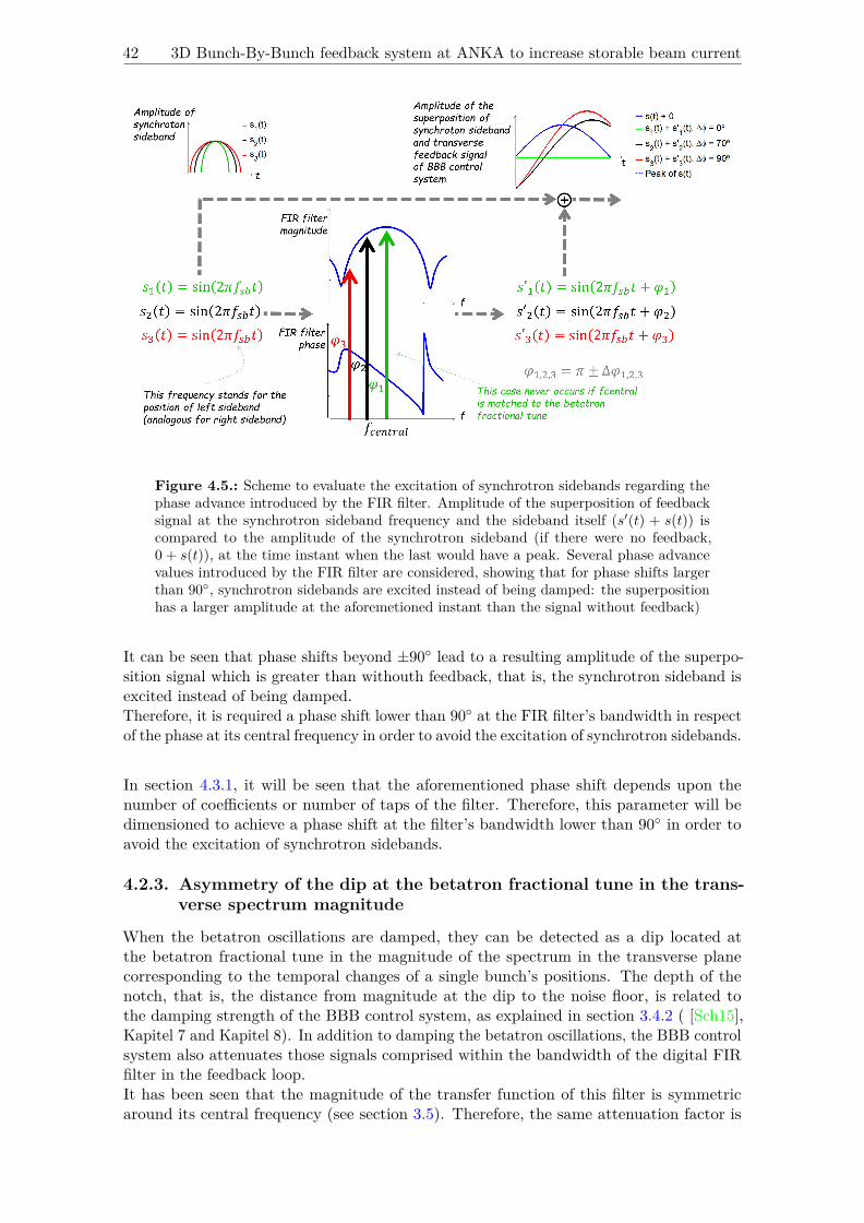
42 3D Bunch-By-Bunch feedback system at ANKA to increase storable beam current
Figure 4.5.: Scheme to evaluate the excitation of synchrotron sidebands regarding thephase advance introduced by the FIR filter. Amplitude of the superposition of feedbacksignal at the synchrotron sideband frequency and the sideband itself (s′(t) + s(t)) iscompared to the amplitude of the synchrotron sideband (if there were no feedback,0 + s(t)), at the time instant when the last would have a peak. Several phase advancevalues introduced by the FIR filter are considered, showing that for phase shifts largerthan 90◦, synchrotron sidebands are excited instead of being damped: the superpositionhas a larger amplitude at the aforemetioned instant than the signal without feedback)
It can be seen that phase shifts beyond ±90◦ lead to a resulting amplitude of the superpo-sition signal which is greater than withouth feedback, that is, the synchrotron sideband isexcited instead of being damped.Therefore, it is required a phase shift lower than 90◦ at the FIR filter’s bandwidth in respectof the phase at its central frequency in order to avoid the excitation of synchrotron sidebands.
In section 4.3.1, it will be seen that the aforementioned phase shift depends upon thenumber of coefficients or number of taps of the filter. Therefore, this parameter will bedimensioned to achieve a phase shift at the filter’s bandwidth lower than 90◦ in order toavoid the excitation of synchrotron sidebands.
4.2.3. Asymmetry of the dip at the betatron fractional tune in the trans-verse spectrum magnitude
When the betatron oscillations are damped, they can be detected as a dip located atthe betatron fractional tune in the magnitude of the spectrum in the transverse planecorresponding to the temporal changes of a single bunch’s positions. The depth of thenotch, that is, the distance from magnitude at the dip to the noise floor, is related tothe damping strength of the BBB control system, as explained in section 3.4.2 ( [Sch15],Kapitel 7 and Kapitel 8). In addition to damping the betatron oscillations, the BBB controlsystem also attenuates those signals comprised within the bandwidth of the digital FIRfilter in the feedback loop.It has been seen that the magnitude of the transfer function of this filter is symmetricaround its central frequency (see section 3.5). Therefore, the same attenuation factor is

Chapter 4. Algorithm for automatic FIR filter tuning in the transverse BBB feedback 43
expected for signals located at the same distance from the central frequency, regardless ifthey are below or above it, as long as they are comprised within the filter bandwidth.As a consequence of this symmetric attenuation, if the filter’s central frequency is matchedto the betatron tune, signals located around of it (within the filter bandwidth) will bedamped in the same amount. Therefore, a symmetric dip is expected in the spectrummagnitude when the BBB control is correctly tuned to the betatron fractional tune. Inother words, when the betatron tune is shifted during energy ramping, the dip in thespectrum will become asymmetric; the greater the shift in the tune, the more severe theasymmetry.
The assymetry of the dip reveals a detuning of the BBB control system, which has theeffects presented in the former section (it can lead to excitation of CBI instead of damping).This asymmetry can be used to measure the detuning of the control system during energyramping, and thus it enables rating the effectiveness of the automatic FIR filter tuningalgorithm proposed in this work.Asymmetry of the dip at betatron tune can be quantified in terms of its mean value atevery level of energy during ramping. The method used for its calculation for a givenenergy value is depicted at Figure 4.6 (the associated Matlab code is provided in AppendixC); it consists of the following steps:
• First, the magnitude of the spectrum of the horizontal or vertical axes is cropped inthe frequency range in which the asymmetry will be calculated. This range comprisesfrequencies between left and right synchrotron sidebands.As it has been seen in section 4.2.2, these sidebands are located above and below thebetatron fractional tune at a distance corresponding to the synchrotron fractionaltune. Since the last has a change with energy almost ten times smaller than thevariation in the betatron tune (see 4.1c), the position of the synchrotron sidebands isconsidered as a constant distance, which enables comparing the asymmetry obtainedfor the different energy levels and among several rampings.
• Next, the cropped signal is split in halves around the betatron fractional tune. Thedifference between these halves is obtained by subtracting the magnitude of samplesopposite in each side of the fractional betatron tune (the tune itself is not considered).With this, a vector of half the length of the original, cropped spectrum magnitude isobtained.
• Finally, the average of this vector is computed, providing one single value to quantifythe notch asymmetry at a given energy level.
This process is repeated for the several stages during energy ramping, thus providing a setof values which quantify the detuning of the BBB transverse feedback system during theramp.
4.2.4. Partial beamloss during energy ramping
The rise of CBI can provoke partial or total beamloss. In order to avoid these effects, aBBB control system properly matched to the betatron tune is required, for this providesthe appropriate damping of CBI.Before reaching the point of total beamloss, the evaluation of the partial beamloss is anindirect measurement of the transverse BBB control mismatch - the lower the loss, thebetter the tuning of the feedback system.Beamloss is evaluated in terms of the beam current, which is measured using a DC currenttransformer (DCCT, [CVCMb]) and it can be obtained by reading the corresponding signal

44 3D Bunch-By-Bunch feedback system at ANKA to increase storable beam current
Figure 4.6.: Method to quantify the asymmetry of the dip in the transverse spectrummagnitude in terms of its average value
or PV on the EPICS interface. Partial beamloss is computed as defined in expression 4.1,with I(t) the beam current, tstart and tend the initial and final points of the ramp respectively.
Loss = I(tstart)− I(tend)I(tstart)
(4.1)
4.3. Algorithm for the automatic FIR filter tuning in the transverse BBBcontrol system
The action of transverse BBB control system is aimed to take place centered at the betatronfractional tune, in order to damp the oscillations of the beam in the transverse plane. Dueto the variation of betatron tune with energy, the transverse BBB control becomes detunedduring energy ramping, which deteriorates its performance: damping of CBI is reducedand the excitation of instabilities can occur instead, which can even provoke beamloss.The digital FIR filter which provides this control action must fulfill the requirements intro-duced in section 3.5. Among them, the filter should have a narrow frequency response inorder to reject detector noise and focus the control action at the frequency of the oscillationto be damped ( [FCM+], p.14).A narrow frequency response has the limitation that the central frequency of the filtermust be accurately adjusted to the betatron tune, which varies during energy ramping. Soas to overcome this limitation, the present configuration of the filter in transverse BBBfeedback in ANKA (see Table A.2) provides a broadband, flat transfer function, especiallyfor the vertical case, as it can be seen in Figure 4.7. This enables applying the feedbackaction over a wider range of frequencies, at the expense of reducing the efectiveness of CBIdamping. And yet even with a broadband filter, feedback must be switched off some timesduring energy ramping to avoid beamloss.
In order to avoid feedback detuning and, at the same time, be able to operate with anarrowband filter, this work proposes an algorithm for the automatic tuning of the FIRfilter in the transverse BBB control loop, which a) tracks the betatron tune during energyramping and readjusts the central frequency of the filter accordingly; and b) configuresthe filter gain and number of coefficients to optimize its frequency response regarding therequirements presented in section 3.5.

Chapter 4. Algorithm for automatic FIR filter tuning in the transverse BBB feedback 45
In addition to enhancing the performance of the transverse BBB control during energyramping, automatic FIR filter tuning opens the door to custom optics settings, e.g. for thegeneration of THz radiation in the so-called low-alpha mode.In this section, the algorithm for the automatic FIR filter tuning is presented, explainingwhich parameters are configured, which criteria is used for their adjustment and the stepsthat compose the algorithm.
(a) Frequency response of the horizontalFIR filter
(b) Frequency response of the verticalFIR filter
Figure 4.7.: Frequency response of the FIR filter calculated as the FFT of equation 3.10for coefficients in Table A.2. The central frequency is marked as a green spot
4.3.1. Configurable parameters and criteria to dimension the digital FIRfilter
The filter in the transverse BBB feedback is a digital, bandpass, selective FIR filter whoseimpulse response (filter coefficients) is a sampled sinusoid with frequency equal to its centralfrequency - in the nominal case, the betatron fractional tune. Its main characteristics werealready presented in section 3.5; in the present section, its features are particularized forthe filter in ANKA.The coefficients of this filter are computed regarding expression 3.10 ( [Sch15], pp.57-58).Parameters available for its configuration are the following:
• Central frequency normalized to revolution frequency: Qfrac ∈ [0, 1]. It is set tomatch the betatron fractional tune (normalized to ωo), so that the control actiontakes place centered at this frequency.
• Central phase: φ ∈ [−180◦, 180◦]. It is is determined once (callibrated during machinesetup) and it is not affected by the energy variation. Its nominal value is 180◦ (so asto provide negative and purely resistive feedback), but its actual dimension may bedifferent so as to compensate for delays introduced by the electronics. This parameteris not adjusted with the algorithm presented in this work, but manually tuned.
• Shift gain (g ∈ [0, 7], coarse magnitude tuning) and central gain (G ∈ [0, 1], finemagnitude tuning) should be big, so as to provide the required feedback gain todamp CBI; however, the BBB feedback system using a FIR filter as a controller isconditionally stable, which means it is stable only over a finite range of loop gains. Ifthe shift and central gains are too big, feedback instability is provoked, which can

46 3D Bunch-By-Bunch feedback system at ANKA to increase storable beam current
lead to beamloss. Therefore, feedback damping will be limited to the maximum gainand shift gain that do not provoke feedback instability ( [HEF+93], p.2).These gains are set at the beginning of the energy ramp to the maximum value whichdoes not provoke beamloss.
• Number of taps (Ntaps ∈ [1, 32], the number of coefficients of the filter). It is relatedto the filter bandwidth (the -3dB bandwidth is considered in this work): the higherthe number of taps, the narrower the bandwidth achieved, and the reverse - Ntaps = 1provides a flat frequency response. In addition, Ntaps also defines the slope of thephase response of the filter and, as a consequence, the phase shift between thebandwidth and the central frequency.
As explained in section 4.2.2, the number of taps should provide a phase shift betweenthe bandwidth and the central frequency lower than 90◦ in order to avoid exciting thesynchrotron sidebands that appear in the transverse spectrum. This phase limit correspondsto the ideal case when the phase advance in the feedback loop is provided exclusively bythe FIR filter.However, additional delays might be introduced by the electronics, for instance due toparasitic losses of the coaxial cables. Coaxial cables in the order of 30m connect the detectorand the processor, which regarding [AL97], p.11 will introduce a delay lower than a hundredof nanoseconds. In turn, this time lapse can be expressed in terms of a phase delay bymultiplying it times the frequency of operation.In section 4.1, it was explained that betatron fractional tunes observed during energyramping are in the order of 600kHz for the horizontal axis and 800kHz for the vertical axis;and the synchrotron fractional tune is in the order of 36kHz. Taking this into account,synchrotron sidebands will appear approximately at frequencies (600.0± 3.6) kHz in thehorizontal axis and (800.0± 3.6) kHz in the vertical axis.The greatest delay in terms of phase due to the electronics will occur with the highest of theaforementioned frequencies, that is, 836kHz. If the effect due to coaxial cables is consideredthe dominant contribution to the delays, the phase delay associated to electronics can becalculated as 2 · π · 836 kHz70 ns · 180/π ≈ 20◦.This rough estimate of the additional delay introduced by the electronics is considered as asafety margin to define the maximum phase shift allowed between the bandwidth and thecentral frequency: 70◦ maximum phase shift instead of the nominal 90◦ is considered.
Figure 4.8 shows the effect of the number of taps of the filter on the phase shift between thebandwidth and the phase at the central frequency. These values have been obtained fromthe phase response of the filter defined by parameters in Table A.2 and with coefficientscalculated applying the equation 3.10, when a sweep in the number of taps is performed.Horizontal and vertical cases are superimposed.The red, dashed line in this figure stands for the nominal, maximum phase shift allowedbetween the bandwidth and the central frequency; and the green, dashed line correspondsto the actual limit considered, i.e. 70◦. The biggest circles indicate which numbers of tapsprovide a phase shift below the maximum of 70◦ allowed.It can be seen that there is more than one possible configuration for the number of tapswhich complies with the maximum phase shift allowed. In order to determine which ofthese will be used to configure the filter, the obtained bandwidth is used: as explained insection 3.5, a narrow bandwidth is required to reject detector noise and focus the controlaction at the frequency of the oscillation to be damped ( [FCM+], p.14).

Chapter 4. Algorithm for automatic FIR filter tuning in the transverse BBB feedback 47
Figure 4.8.: Phase shift introduced by the FIR filter (phase advance at its bandwidthin respect of the phase at its central frequency) as a function of the number of taps.The theoretical maximum phase shift allowed in order to avoid exciting the synchrotronsidebands is indicated with a red, dashed line; the maximum phase shift allowed consideredin the presented algorithm corresponds to the green, dashed line
Figure 4.9 shows the filter bandwidth as a function of the number of taps, using the samefilter coefficients for Figure 4.8. Horizontal and vertical cases are superimposed and thebiggest circles indicate which numbers of taps provide a phase shift between the bandwidthand the central frequency below the maximum of 70◦ allowed.To illustrate that synchrotron sidebands are comprised within the filter bandwidth, asit has been mentioned before, the red, dashed line indicates the usual position of thesesidebands during energy ramping, i.e. the distance between the sideband and the fractionalbetatron tune. This distance, as presented in section 3.2, corresponds to the synchrotronfractional tune, which is in the order of 36 kHz during energy ramping.Among the candidate number of taps, the value providing the narrowest bandwidth isselected as the optimal configuration.
To summarize, criteria to dimension the filter configurable parameters using the automatictuning algorithm are the following:
• Central frequency is set to the betatron fractional tune in the corresponding level ofenergy during ramping.
• Central gain and shift gain are dimensioned at the beginning of the ramping to be asbig as possible, without provoking the instability of the feedback loop.
• Number of taps is such, that it provides a maximum phase shift between the centralfrequency and the bandwidth of ±70◦; and the narrowest possible bandwidth.
In the next section, the algorithm to achieve the optimal dimension of FIR parameters inan automatic way following the aforementioned criteria is presented.
4.3.2. Algorithm for automatic FIR filter tuning
Due to the variation of betatron tune during energy ramping, an algorithm for the automatictuning of the FIR filter in the BBB transverse control is required in order to readjust the

48 3D Bunch-By-Bunch feedback system at ANKA to increase storable beam current
Figure 4.9.: Bandwidth of the FIR filter and as a function of the number of taps. Thedistance between the synchrotron sidebands and the betatron fractional tune, whichcorresponds to the synchrotron fractional tune, is indicated with a red, dashed line
feedback accordingly to the change in the tune. By doing so, the control action is lockedto the tune and the appropriate performance of the transverse BBB can be guaranteedduring energy ramping.This algorithm is composed of two parts:
• On the one hand, the filter shift gain and central gain are configured before thebeginning of the energy ramp. They are set to the maximum value which does notprovoke the instability of the feedback loop, since this will provide the maximumstrength of the feedback to damp CBI.The procedure followed for their dimension is explained next.
• On the other hand, the filter central frequency and number of taps are updatedperiodically during the energy ramp in order to track the change in the betatronfractional tune with energy. This update is performed at a maximum frequency of5Hz, which is the highest rate allowed by the BRAM acquisition module (from whichthe spectra used by the algorithm are obtained), but it might be lower depending onthe settings of the BBB control system.The procedure use to set these parameters is depicted at Figure 4.10. First, thebetatron fractional tune corresponding to a given level of energy is detected by meansof the method explained in section 4.1. The central frequency of the filter is set tothis value by modifying the corresponding signal or PV of the EPICS interface.Second, the number of taps is set to its optimal value for that level of energy bymodifying the corresponding signal or PV of the EPICS interface. The procedurefollowed to determine the optimal number of taps is explained next.
Configuration of shift gain and central gain of the FIR filter before theenergy ramp
The shift gain, which provides a coarse tuning of total filter gain at its central frequency, isadjusted first. Starting from its minimum value (0), it is progressively incremented untilits maximum value is achieved (7) or until feedback instability is provoked. This instabilitycan be detected in two ways:

Chapter 4. Algorithm for automatic FIR filter tuning in the transverse BBB feedback 49
Figure 4.10.: Steps of the algorithm for automatic FIR filter tuning which are executedperiodically during energy ramping
• Betatron tune is detected in a peak instead of a dip in the magnitude of the cor-responding spectrum. This means that instabilities are excited instead of beingattenuated.
• Beamloss is produced, which is detected as a drop in the beam current below aminimum threshold (0.1 mA is considered).
If either of above conditions are matched, shift gain is set to the value immediately lowerthan that provoking instability. Finally, the signal or PV of the EPICS interface corre-sponding to the FIR filter’s shift gain is set to the obtained value.With the achieved shift gain value, the central gain is iterated in the same way, startingfrom the minimum value (0) and increasing until its maximum value is achieved (1) or untilfeedback instability is provoked, which is detected analogously as for the shift gain. If eitherof the two conditions are matched, the central gain is set to the value immediately belowthat provoking instability. Finally, the signal or PV of EPICS interface corresponding tothe FIR filter’s central gain is set to the obtained value.At this point, shift gain and central gain are configured to the maximum allowed valuewhich does not provoke feedback instability.
Dimension of the optimal number of taps of the FIR filter for a given level ofenergy during ramping
Regarding the criteria defined in section 4.3.1, the optimal number of taps for a givenlevel of energy during ramping is such, that the phase shift between the central frequencyand the bandwidth of the filter is lower than ±70◦ and it provides the narrowest possiblebandwidth.The phase at the central frequency, shift gain and central gain have a fix value duringthe energy ramp. Therefore, the optimal number of taps will only vary with the centralfrequency of the filter, which tracks de evolution of the betatron tune.As a consequence, the optimal number of taps can be computed for all the expected values

50 3D Bunch-By-Bunch feedback system at ANKA to increase storable beam current
of the fractional betatron tune (its range of variation can be seen in Figure 4.1) and storedas a lookup table: instead of recomputing the optimal number of taps for every value ofenergy during ramping, the detected betatron fractional tune is matched to the storedoptimal number of taps and the signal or PV of EPICS interface corresponding to the FIRfilter’s number of taps is set to this value.
The computation of the optimal number of taps is performed as follows: the filter coefficientsare calculated regarding expression 3.10, for the phase at central frequency defined in TableA.2 and a constant value for shift and central gains (both equal to 1).The value of these gains does not affect the obtained optimal number of taps: the totalgain at the central frequency (2gG regarding expression 3.10) will introduce a scaling inthe amplitude response of the filter, but it will not change the slope of its phase response,which is used to determine the optimal number of taps.To compute the filter coefficients, a sweep is performed in respect of the number of taps,which leads to a pair of curves as those depicted at Figure 4.8 and Figure 4.9. The criteriato dimension the optimal number of taps is applied: regarding Figure 4.8, a subset isdetermined with those numbers of taps that provide a phase shift between the bandwidthand the central frequency below 70◦. Out of them, that providing the narrowest bandwidthis selected using Figure 4.9.This procedure is implemented with Matlab as indicated in Appendix C. The obtainedoptimal number of taps for the betatron fractional tunes in the range of variation observedin Figures 4.1a and 4.1b is depicted at Figure 4.11.
The algorithm for automatic tuning of the FIR filter in the transverse BBB control systemhas been implemented in C++ (code is provided in Appendix B) and it is to be integratedas an additional feature in the EPICS interface. It has been tested in ANKA and theevaluation of the obtained results is presented next.
4.4. Discussion on results obtained with automatic FIR filter tuning
Several energy rampings were performed in the ANKA storage ring in order to assess theenhancement of performance of the transverse BBB control system with the automatic FIRfilter tuning. Performance of the rampings in which this algorithm was disabled will becompared to those rampings in which it was applied.This section presents the results obtained in terms of issues and methods presented insections 4.2 and 4.3, namely: the excitation of betatron CBI and synchrotron sidebands,the asymmetry of the dip in the spectrum magnitude at betatron fractional tune and thepartial beamloss observed during energy ramping.
4.4.1. Effect of the automatic FIR filter tuning on the damping of beta-tron CBI and synchrotron sidebands
Measurement of the magnitude at the at betatron fractional tune in the spectrum corre-sponding to the temporal changes of a single bunch’s positions reflects the strength of thetransverse BBB feedback when damping the CBI in this plane: the lower this magnitude,that is, the deeper the dip in the spectrum, the better the attenuation ( [Sch15], Kapitel 7and Kapitel 8).Another effect of CBI are the synchrotron sidebands that appear due to the coupling of the

Chapter 4. Algorithm for automatic FIR filter tuning in the transverse BBB feedback 51
(a) Optimal number of taps for horizontal axis as a function of horizontal fractional tune
(b) Optimal number of taps for vertical axis as a function of vertical fractional tune
Figure 4.11.: Optimal number of taps as a function of the FIR central frequency (betatronfractional tune expressed in kHz) for central gain = shift gain = 1

52 3D Bunch-By-Bunch feedback system at ANKA to increase storable beam current
longitudinal to the transverse plane, as explained in section 3.4.1. The lower the magnitudeof the spectrum at the synchrotron sidebands, the more robust will be the transversefeedback against the synchrotron instabilities.
Regarding the damping at the betatron fractional tune, Figure 4.12a and 4.12b show themagnitude of horizontal and vertical spectra respectively, measured at the correspondingbetatron fractional tune. As for synchrotron sidebands, Figure 4.12c and 4.12d show themagnitude of horizontal and vertical spectra respectively, measured at the synchrotronsideband frequency.Three rampings are superimposed in each case: in one of them, automatic FIR filter tuningwas disabled and ramping was performed with the coefficients of the FIR filter in TableA.2; for the other two, automatic tuning was applied in the axis to be evaluated.The results are cropped to those levels of energy in which the most significant effect achievedwith the automatic tuning is observed.
(a) Magnitude at the horizontal frac-tional tune
(b) Magnitude at the vertical fractionaltune
(c) Magnitude at the synchrotron side-band in the horizontal spectrum
(d) Magnitude at the synchrotron side-band in the vertical spectrum
Figure 4.12.: Evolution of the magnitude of the transverse spectrum (obtained from theBRAM acquisition module) at the synchrotron sideband and at the betatron fractionaltune frequencies as a function of energy during ramping. The range of energy displayedis that in which the effect of the automatic FIR filter tuning algorithm is most significant
At first glance, it can be seen that the magnitude at the fractional tune and also at thesynchrotron sideband have a lower variability when ramping with the automatic FIR filtertuning enabled. This means that the system has a more constant performance during theramp, with the benefit that fewer adjusments are required in the optics of the accelerator,amongst others ( [Kei03], p.11).Automatic tuning also shows a significant enhancement in terms of damping of CBI:horizontal oscillations are more attenuated than in the case of the fix-parameter filter, witha maximum improvement of 5 dB (that is, the magnitude at this frequency is 5dB lowerthan in the case of the fix-parameter filter) located at a 0.9 GeV energy level. A maximumimprovement of 3 dB in respect of the fix-parameter filter is observed in the vertical axis,located at 0.8 GeV.

Chapter 4. Algorithm for automatic FIR filter tuning in the transverse BBB feedback 53
Damping of synchrotron sideband is improved as well: in the horizontal axis, the magnitudeat this frequency is a maximum of 4 dB lower than in the case of the fix-parameter filter at0.87 GeV; and a maximum improvement of 3 dB is measured at 0.82 GeV for the verticalaxis.The maximum enhancement is thus achieved at low levels of energy. It can be explained asfollows:
• At the higher energy levels of the ramp, more power is required by the kicker to deflectthe beam, that is, the control action is not as effective as with lower energies. Thisoccurs because a high-energy electron beam is stiff and largely confined by its ownmagnetic fields ( [Hum86], p.346). In addition, the effect of CBI is not as significantas for the lower energies, because the natural or radiation damping is more intense(radiated power is proportional to the fourth power of energy), so the action of theBBB control system is not as strong as in the lower energy levels.
• For the lower energies of the ramp, CBI are stronger because the natural damping ismore limited. On the other hand, a lower power is required by the kicker to deflectthe beam, which makes the feedback more effective at these energies.
The convergence of these two factors, a lower natural damping (which means the beamis more unstable) and a larger effect of the kicker with lower powers, provides the mostsignificant enhancement achieved with automatic FIR filter tuning at the lower energies ofthe ramp.
4.4.2. Effect of the automatic FIR filter tuning on the asymmetry of thedip at the betatron fractional tune
As presented in section 4.2, the assymetry of the dip in the magnitude of the transversespectrum corresponding to the temporal changes of a single bunch’s positions reveals thedetuning of the BBB control, which can lead to the excitation (instead of damping) of CBI.The asymmetry is evaluated as the mean value of the difference in the spectrum magnitudeat frequencies located above and below the betatron fractional tune in the range delimitedby the synchrotron sidebands.Figure 4.13a shows the evolution of the average dip asymmetry with energy correspondingto the horizontal axis, and so does Figure 4.13b for the vertical axis. Three rampings aresuperimposed in each case: in one of them, automatic FIR filter tuning was disabled andthe ramp was performed with the filter coefficients in Table A.2; for the other two, it wasapplied in the axis to be evaluated. Results are cropped to the same levels of energy as insection 4.4.1 in order to compare the performance with that observed in terms of dampingof CBI and synchrotron sidebands.
A very similar average asymmetry is observed when the automatic tuning is appliedand when it is disabled, which should mean that the presented algorithm does not providethe required readjustment of the transverse BBB feedback during the ramp. However,the enhancement of performance associated to the proper retuning has been observed insection 4.4.1, which indicates that the betatron fractional tune is correctly tracked duringthe ramp.The divergence of results might be due to the low resolution of the spectrum from whichthe asymmetry is computed. In the present measurement, the BRAM acquisition modulewas used, which provides an acquisition window up to 0.57 ms. In order to achieve abetter resolution and thus verify the consistency of the computed mean asymmetry, furthermeasurements can be performed using the SRAM acquisition module, which provides anacquisition window up to 25.2 ms.

54 3D Bunch-By-Bunch feedback system at ANKA to increase storable beam current
(a) Evolution of the mean asymmetry of the dipin the horizontal spectrum magnitude. One casewhen automatic FIR filter tuning was disabledand two in which it was applied in the horizontalaxis are superimposed
(b) Evolution of the mean asymmetry of the dip inthe vertical spectrum magnitude. One case whenautomatic FIR filter tuning was disabled and twoin which it was applied in the vertical axis aresuperimposed
Figure 4.13.: Evolution of the mean asymmetry of the dip in the betatron spectrummagnitude with energy during ramping. The range of energy displayed is that in whichthe effect of the automatic tuning algorithm is most significant
4.4.3. Effect of the automatic FIR filter tuning on the partial beamlossduring energy ramping
Partial or total beamloss can occur during energy ramping due to the effect of CBI. As anexample of the partial beamloss, Figure 3 in [LCC+] shows the current decay with energyduring rampig in the case of the SRRC storage ring.Figure 4.14 shows the decay in the beam current recorded during several energy rampingsin the case of ANKA. In subfigure 4.14a, three rampings are superimposed in which theautomatic FIR filter tuning was disabled. Two rampings with automatic tuning applied inthe horizontal axis are superposed in subfigure 4.14b, and two rampings with automatictuning in the vertical axis are shown in subfigure 4.14c. Beam current has been measuredonce for every energy level during the ramp.Two numbers are displayed in the legend for each of the cases: the first stands for partialbeamloss computed regarding expression 4.1. The second is the absolute value of the slopeof beam current decay, if it were fitted with a linear approximation (computed as initialminus final beam currents, divided over total energy variation).In subfigures 4.14b and 4.14c, a very steep initial beam decay is observed. This can bedue to the settings of optics ( [Kei03], p.11) and possible timing shifts between the powersupplies ( [BFH+08], p.93), a mismatch which could be intensified due to the poor vacuumconditions under which the measurements were performed. As these effects are not relatedto the BBB control system, this initial, steep decay is skipped for the computation ofpartial beamloss and beamloss slope, which are calculated from the energy level markedwith the red, dashed line.
At first glance, no clear improvement in terms of partial beamloss is observed with automatictuning. The case depicted in light blue in subfigures 4.14b and 4.14c is deceitful: a lowerloss is obtained; however, this ramping was performed at a different initial current as therest of rampings, so the observed loss is not strictly comparable.
The actual benefit of automatic FIR filter tuning is achieved in terms of the slope ofpartial beamloss: when it is enabled, this slope is reduced up to a factor of 3 in respect ofthe case with the fix-parameters filter. This means that the system has a more constantperformance during the ramp, with the benefit that fewer adjustments are required in theoptics of the accelerator, amongst others ( [Kei03], p.11).

Chapter 4. Algorithm for automatic FIR filter tuning in the transverse BBB feedback 55
(a) Decay of the beam current with energy without automatic FIR filter tuning
(b) Decay of the beam current with energy when automatic FIR filter tuning is applied in thehorizontal axis
(c) Decay of the beam current with energy when automatic FIR filter tuning is applied in thevertical axis
Figure 4.14.: Beam current decay during energy ramping; three rampings withoutautomatic FIR filter tuning, two with automatic tuning applied in the horizontal axisand two with automatic tuning applied in the vertical axis are shown. In the cases whenautomatic FIR filter tuning is applied, the partial beamloss and the slope of beam currentdecay are computed from the red, dashed line (the steep initial decay is not consideredbecause is not related to the BBB control system)

56 3D Bunch-By-Bunch feedback system at ANKA to increase storable beam current
It has been seen that the performance of the transverse BBB control system can be enhancedwith an automatic FIR filter tuning algorithm that readjusts the FIR filter parametersduring energy ramping. A higher damping of CBI and synchrotron sidebands and a lowerslope of partial beamloss (beam current decay) during energy ramping have been achieved.In the next chapter, a solution to enhance the peformance of longitudinal BBB control ispresented, which will be applied at injection energy.

5. Algorithm for the automatic tuning ofthe DAC Drive arbitrary signalgenerator in the longitudinal feedback
As presented in section 2.5, the beam lifetime can be limited by several factors, such as thegas scattering effects, the intrabeam scattering or Touschek effect, the quantum effects oras a result of CBI. When CBI are not limiting and vacuum pressure is below the residualgas pressure, the Touschek effect becomes the dominant factor. These are the conditionsthat apply for the contribution presented in this chapter.
A short bunch length in the longitudinal axis is required for the proper operation of theundulators. These are periodic structures of dipole magnets that stimulate the emission ofhighly brilliant synchrotron radiation.Usual values for bunch length are a few hundreds of µm (compare [KPPL08], [MTH+07],[KKJ+16]). However, for too short a bunch length, the Touschek effect, i.e. the intrabeamscattering or collisions among particles inside the bunch when they perform oscillationsrevolving about the ring, decreases the beam lifetime and can lead to particle loss, thusdeteriorating the performance of the storage ring [Wol09b].Since a long lifetime is critical for the proper performance of the ring ( [SIM+00], p.690), acorrection method is required to increase the bunch length, for this will reduce the particledensity. With this, the probability of intrabeam scattering will be reduced and the beamlifetime will be enhanced ( [WN13], p.25; [Wie07], p.573). Effects of intrabeam scatteringderived from the betatron and longitudinal motion are projected into the longitudinal plane( [Piw98], p.2); in addition, intrabeam scattering is most significant at low energies (below1.0 GeV regarding [Boc03], p.7). Therefore, the correction action presented in this chapterto increase the bunch length will be applied on the longitudinal axis at injection energy(0.505 GeV for ANKA).
A method for increasing the bunch length and thus enhancing the beam lifetime wasintroduced in section 2.5. In ANKA, an analogous solution using the longitudinal BBBcontrol system is implemented: by exciting the quadrupole eigenfrequency of the beamin the longitudinal axis, the bunch length in this axis is incremented and thus the beamlifetime is enhanced. The quadrupole resonance is excited by adding a sinusoid of this veryfrequency to the longitudinal feedback signal generated by the BBB control system.This is achieved by means of the DAC Drive arbitrary signal generator, which is locatedin the BBB control loop (see Figure 3.3). This module provides an analog waveform ofconfigurable frequency and amplitude (amongst other parameters) which is superimposedto the control action and sent to the RF power amplifer and later to the kicker, reaching
57
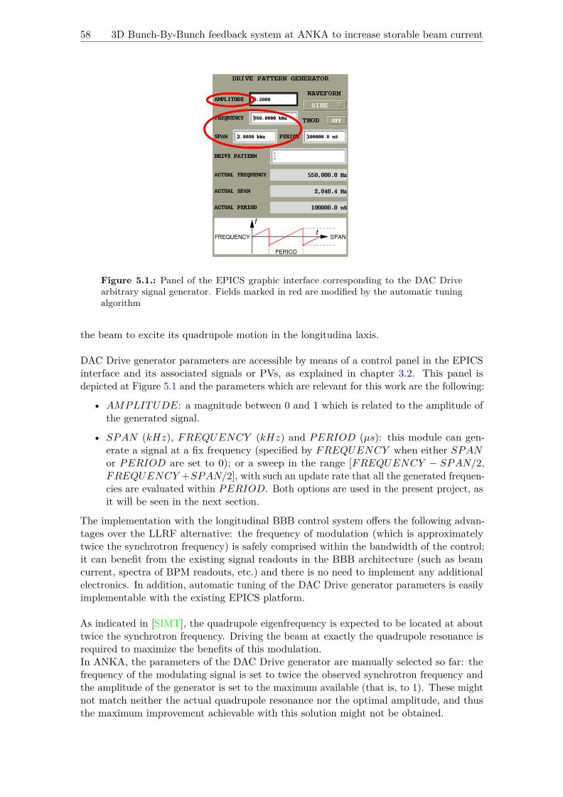
58 3D Bunch-By-Bunch feedback system at ANKA to increase storable beam current
Figure 5.1.: Panel of the EPICS graphic interface corresponding to the DAC Drivearbitrary signal generator. Fields marked in red are modified by the automatic tuningalgorithm
the beam to excite its quadrupole motion in the longitudina laxis.
DAC Drive generator parameters are accessible by means of a control panel in the EPICSinterface and its associated signals or PVs, as explained in chapter 3.2. This panel isdepicted at Figure 5.1 and the parameters which are relevant for this work are the following:
• AMPLITUDE: a magnitude between 0 and 1 which is related to the amplitude ofthe generated signal.
• SPAN (kHz), FREQUENCY (kHz) and PERIOD (µs): this module can gen-erate a signal at a fix frequency (specified by FREQUENCY when either SPANor PERIOD are set to 0); or a sweep in the range [FREQUENCY − SPAN/2,FREQUENCY +SPAN/2], with such an update rate that all the generated frequen-cies are evaluated within PERIOD. Both options are used in the present project, asit will be seen in the next section.
The implementation with the longitudinal BBB control system offers the following advan-tages over the LLRF alternative: the frequency of modulation (which is approximatelytwice the synchrotron frequency) is safely comprised within the bandwidth of the control;it can benefit from the existing signal readouts in the BBB architecture (such as beamcurrent, spectra of BPM readouts, etc.) and there is no need to implement any additionalelectronics. In addition, automatic tuning of the DAC Drive generator parameters is easilyimplementable with the existing EPICS platform.
As indicated in [SIMT], the quadrupole eigenfrequency is expected to be located at abouttwice the synchrotron frequency. Driving the beam at exactly the quadrupole resonance isrequired to maximize the benefits of this modulation.In ANKA, the parameters of the DAC Drive generator are manually selected so far: thefrequency of the modulating signal is set to twice the observed synchrotron frequency andthe amplitude of the generator is set to the maximum available (that is, to 1). These mightnot match neither the actual quadrupole resonance nor the optimal amplitude, and thusthe maximum improvement achievable with this solution might not be obtained.

Chapter 5. Algorithm for the automatic tuning of the DAC Drive arbitrary signalgenerator in the longitudinal feedback 59
The contribution of the present project to the longitudinal BBB control system is analgorithm for the automatic tuning of the DAC Drive generator parameters to ensure thatthe modulating sinewave is located at the quadrupole motion resonance and its amplitudeis the optimal one.In this section, the aforementioned algorithm is explained; then the methods used forevaluating its performance and the obtained results are presented.
5.1. Algorithm for the automatic tuning of the DAC Drive generatorparameters to enhance beam lifetime
The algorithm for the automatic tuning of the DAC Drive generator, which determinesthe signal to be applied in order to modulate the quadrupole resonance of the beam inthe longitudinal axis, is executed before the injection. Then the injection is performedwith the aforementioned signal superimposed to the longitudinal BBB control signal. Withthis, the quadrupole resonance of the beam in this axis is excited, which will increasethe corresponding bunch length; this, in turn, will reduce the probability of intrabeamscattering and thus will provide an enhancement in the Touschek lifetime ( [SIMT], p.11).The algorithm is composed of two main steps, as depicted at Figure 5.2, which are explainednext.
Step 1: Dimension of the frequency of the DAC Drive generator
The frequency of the DAC Drive generator is set to the quadrupole resonance of the beamin the longitudinal axis. Its value is determined as follows: first, the same method explainedin section 4.1 is applied to determine the synchroton fractional tune using the magnitudeof the longitudinal spectrum in Figure 3.8c, which corresponds to the temporal changesin a single bunch’s positions in the longitudinal axis. Then a sweep in frequency withSPAN = 0.4kHz (this value has been determined experimentally, it provides the desiredfunctionality) around twice the synchrotron fractional tune (FREQUENCY = 2Qsfo) isperformed, since the quadrupole resonance is expected in this range [SIMT]. PERIOD isset to 1/10 times the acquisition time of the BRAM module, from which the spectra areobtained, to ensure that the whole sweep is covered within the acquisition window of themodule.The magnitude of the longitudinal spectrum is evaluated again: in the range determinedby SPAN around the configured FREQUENCY , a peak is detected for every frequencyprovided by the DAC Drive generator. The peak with the largest amplitude correspondsto the quadrupole resonance (in the longitudinal axis) because it is an eigenfrequency ofthe beam.At this point, FREQUENCY is set to the detected quadrupole resonance and SPAN isset to 0 in order to force the generation of a signal at this fix frequency.
Step 2: Dimension of the amplitude of the DAC Drive generator
The AMPLITUDE parameter is a field ranging from 0 to 1 (with 1 providing the highestamplitude of the generated signal). It is expected that the higher the amplitude, themore intense the modulation, and thus the greater the increment in the bunch length.As a consequence of this, a higher possible beam current is also expected [Iei00]. Highercurrents provoke stronger wakefields, which means CBI become stronger and this can leadto beamloss ( [Ues], p.77).Therefore, the strategy to determine the optimal amplitude of the generator proceeds asfollows: starting with its minimum value (0), the amplitude is incremented until a) the

60 3D Bunch-By-Bunch feedback system at ANKA to increase storable beam current
Figure 5.2.: Algorithm for phase modulation using the DAC Drive generator in thelongitudinal BBB control system
beam is lost because the current limit imposed by CBI is reached, which is detected with adrop in the beam current below a given threshold (0.1 mA in the present configuration); orb) the maximum available value (1) is reached and the beam is not lost due to strong CBI.If the first situation occurs, the amplitude is decremented to the immediate value belowthat provoking the beamloss due to strong CBI.
The algorithm for automatic configuration of the DAC Drive generator is implemented inC++ (its code is provided in Appendix B) and is to be integrated as an additional featurein the EPICS interface. The methods used to evaluate its performance and the obtainedresults are discussed next.
5.2. Methods to evaluate the performance of the automatic DAC Drivegenerator tuning algorithm and discussion on the obtained results
Phase modulation (modulation of the longitudinal motion) at the quadrupole resonanceof the beam aims to enhance the beam lifetime by incrementing the bunch length in thelongitudinal axis, because this reduces the Touschek effect. As explained in section 2.5, theTouschek lifetime is proportional to the bunch length in the longitudinal axis, so the firstshould be elongated in the same amount as the second ( [SIMT], p.11).Therefore, the effectiveness of the presented algorithm can be measured in terms of Touscheklifetime. Its value can be obtained from the corresponding signal or PV in the EPICSinterface, and the procedure used for the measurement is the following: first, the algorithmis applied to determine the frequency and optimal amplitude of the signal generated tomodulate the quadrupole resonance of beam in the longitudinal axis. Then the current isinjected into the storage ring. Injection is stopped and, for a fix level of current (otherwisethe lifetime would vary),the lifetime PV is read.

Chapter 5. Algorithm for the automatic tuning of the DAC Drive arbitrary signalgenerator in the longitudinal feedback 61
(a) Lifetime measured when the phase modulationis disabled
(b) Lifetime measured when phase modulationat the quadrupole resonance is applied with auto-matic tuning of the DAC Drive generator parame-ters
Figure 5.3.: Effect of the phase modulation at the quadrupole resonance of the beamon the beam lifetime
Figure 5.3 shows the beam lifetime provided by this PV for the case when phase modulationwas applied with the automatic tuning of DAC Drive parameters and when the modulationwas not applied. At first glance, it might seem that the algorithm provides a radical benefit,for it increases the beam lifetime by a factor of five. However, there are strong limitationson the validity and reproduciblity of this result, for the following reasons:
• Measurements were performed right after a shutdown of the accelerator, which wasforced by the replacement of a damaged component. Linked to this, there was a poorvacuum pressure, which influenced the result: the motivation to apply the phasemodulation is that lifetime is dominated by the Touschek effect, and thus it couldbe enhanced by increasing the bunch length. However, in such vacuum conditions,beam lifetime was most probably limited by the gas scattering effect, as presented insection 2.5. This would mean that the obtained results are not relevant to assess theenhancement in lifetime achieved with the automatic tuning algorithm.
• Only one measurement was performed for each of the cases (phase modulation disabledand automatic tuning of DAC Drive generator parameters with phase modulationenabled).
• Current levels are slightly different in each of the cases.
• Measurement performed when the phase modulation was applied was performed withthe automatic tuning of DAC Drive generator parameters enabled. Therefore, it canbe useful to illustrate the benefits of having this modulation in respect of when it isdisabled; but it does not show if the automatic tuning achieves a better performancein respect of manual tuning, as it has been performed so far in ANKA.
In light of the achieved results and indicated limitations, further measurements are required.
At this point, the two main contributions of this work to the BBB control system in theANKA storage ring have been presented: on the one hand, an algorithm for the automatictuning of the FIR filter parameters in the transverse feedback, which aims to improve itsperformance during energy ramping and thus increase the storable beam current; on theother hand, an automatic tuning algorithm to adjust the DAC Drive generator parametersin the longitudinal feedback, which aims to enhance the beam lifetime at injection energy.In the next section, the achieved results are revisited and discussed.


6. Summary
In this work, two main contributions have been presented which enhance the performanceof the BBB control system in the ANKA storage ring: one the one hand, the storablebeam current is increased by improving the damping of CBI during the energy ramp. Sois achieved by means of an algorithm for the automatic tuning of the FIR filter in thetransverse BBB control system, which tracks the evolution of the betatron tunes withenergy and readjusts the controller in the tranverse BBB feedback accordingly. In additionto improving the performance of the transverse BBB control system, this automatic tuningopens the door to custom optics settings, e.g. for the generation of THz radiation in theso-called low-alpha mode.On the other hand, Touschek beam lifetime is enhanced by modulating the beam at itsquadrupole resonance in the longitudinal axis, which increases the longitudinal bunchlength and thus reduces the Touschek effect. The quadrupole resonance in the longitudinalaxis and the optimal amplitude of the modulating signal are determined by means of anautomatic tuning algorithm.
The algorithm for the automatic tuning of the FIR filter in the transverse BBB feedbackmatches its central frequency to the betatron fractional tune as it changes during energyramping, thus retuning the BBB control system so that the phase advance introducedby the filter at its central frequency provides the required correction action to damp thebetatron oscillations. In addition, this algorithm searches the optimal configuration forthe FIR filter’s gain at its central frequency, which maximizes the damping of betatronoscillations; and the number of coefficients, which avoids exciting the synchrotron sidebands(observed in the transverse spectrum corresponding to the temporal changes of a singlebunch’s positions) while providing the narrowest possible bandwidth.It has been seen that this algorithm can improve the damping of betatron oscillations (upto 5 dB a more intense damping in the horizontal axis and 3 dB in the vertical axis) andthe synchrotron sidebands observed in the aforementioned transverse spectrum (up to 4dB a more intense damping in the horizontal axis and 3 dB in the vertical axis). Thisenhancement takes place at low levels of energy (around 0.8 GeV), at which the feedbackaction is most effective.
An additional benefit obtained with the automatic tuning is that the system has a moreconstant performance during the ramp, which means that fewer adjusments are requiredin the optics of the accelerator, amongst others ( [Kei03], p.11). This benefit is observedin terms of the variability of the magnitude at the betatron fractional tunes and at thesynchrotron sidebands observed in the aforementioned transverse spectrum; this variabilityis reduced.The more constant performance is also observed in terms of beam current: results showthat the slope of the beam current decay during the ramp is reduced up to a factor of 3 in
63

64 3D Bunch-By-Bunch feedback system at ANKA to increase storable beam current
respect of the case with the fix-parameters filter.
Another figure to evaluate the performance of the automatic FIR filter tuning algorithmis the average value of the assymetry of the dip in the magnitude of the aforementionedtransverse spectrum. This value reveals the detuning of the BBB control, which can leadto the excitation (instead of damping) of CBI. The performed measurements show a verysimilar average value of the dip asymmetry when the automatic tuning is applied and whenit is disabled during the energy ramp, which might not reflect the effect of the algorithm:the similarity of results when the automatic tuning was applied and when it was disabledmight be due to the low resolution of the spectrum from which the asymmetry is computed.The BRAM acquisition module was used for these measurements, so the SRAM acquisitionmodule can be used in further tests to achieve a higher resolution and thus be able tocorroborate the enhancement of performance observed in terms of damping of CBI andsynchrotron sidebands.
On the other hand, the algorithm for the automatic tuning of the DAC Drive generatorin the longitudinal axis provides the frequency (the quadrupole resonance of the beam)and the optimal amplitude of the signal which modulates the longitudinal motion of thebeam at its quadrupole resonance, with the aim of enhancing beam lifetime. It has beenmeasured an increase in lifetime by a factor of 5 when the algorithm is applied in respectof the case when the phase modulation is disabled.
In spite of the enhancement observed in performance during the energy ramp and at injectionenergy with the presented algorithms, the validity and reproducibility of these results shouldbe assessed with further measurements. The presented values were obtained right aftera shutdown forced by the replacement of a damaged component, and the measurementconditions were not the nominal ones, so this might have influenced the obtained results.On the one hand, the level of current (in the order of a dozen of mA) was lower than thenominal one (around 150 mA [ANKc]). As a consequence, the effect of CBI might not havelimited the storable beam current, which was the motivation to apply the automatic FIRfilter tuning algorithm in the transverse BBB feedback during energy ramping.On the other hand, the poor vacuum conditions might have provoked that the factor whichlimited the beam lifetime was the gas scattering effect instead of the Touschek effect, whilethe second was the motivation to apply the automatic tuning algorithm in the longitudinalBBB control system in order to configure the signal which modulates the beam at itsquadrupole resonance.Therefore, further measurements under nominal conditions of operation should be performedin order to verify the functionality of the presented algorithms.

Appendix
A. Figures of ANKA storage ring
B. C++ source code corresponding to algorithms presented in this thesis
EPICS interface Code to handle access to PVs using the API implemented by ManuelSchedler
Code: /cplusplus/nep_epicsInterface_20160503.cpp
Generic functionality General purpose code (vector handling, reading EPICS PVs, calcu-lation of eigenfrequencies from the BRAM spectrum magnitude, etc.) invoked by Band B
Code: /cplusplus/nep_general_20160503.cpp
Automatic FIR filter tuning Implementation of the algorithm for automatic FIR filtertuning in the transverse feedback during energy ramping
Code: /cplusplus/nep_autofir_20160503.cpp
Automatic configuration of DAC Drive Implementation of the algorithm for automaticconfiguration of the DAC Drive signal generator in the longitudinal feedback atinjection energy
Code: /cplusplus/nep_phmod_20160503.cpp
Output log Code to generate a text file or print to console the variables acquired fromEPICS interface
Code: /cplusplus/nep_outputtxt_20160503.cpp
C. Matlab code for processing of signals acquired from EPICS interface
Mean asymmetry of dip Computation of the mean value of asymmetry of the notch atbetatron fractional tune in BRAM spectrum magnitude
Code: /matlab/nep_averageasymmetry.m
Detection of synchroton sidebands Detection of synchroton sidebands around betatronfractional tune in the magnitude of transverse BRAM spectrum
Code: /matlab/nep_detectsideband.m
Computation of optimal number of taps Computation of the optimal number of taps ofFIR filter in transverse feedback as a function of betatron tune, for a fix central gain,shift gain and central phase
Code: /matlab/nep_optimaltaps.cpp
65

66 3D Bunch-By-Bunch feedback system at ANKA to increase storable beam current
Table A.1.: Compilation of parameters of the ANKA storage ring
Parameter Value
Harmonic number 184theoretical maximum
bunch repetitionfrequency
500MHz
RF frequency 500MHzRevolution frequency 500/184MHz ≈ 2.7MHz
ADC samplingfrequency 500MHz
ADC samplingfrequency (for 1 single
bunch)500/184MHz ≈ 2.7MHz
Table A.2.: Predetermined FIR filter parameters for the transverse BBB feedback(horizontal/vertical/longitudinal)
FIR filterparameter
Value of the parameter(X/Y/Z)
Central frequencynormalized to
revolution frequency0.22/0.3/0.03
Central phase (º) 79 / 130 / -30Central gain 0.9 / 1 / 1
Number of taps 14 / 3 / 25

Bibliography
[AL97] Ahamed, Syed V. und Victor B. Lawrence: Design and Engineering ofIntelligent Communication Systems. Springer - Science+Business Media, 1997,ISBN 978-1-4613-7888-4.
[ANKa] Accelerator. https://www.anka.kit.edu/965.php. Accessed: 2016-06-04.
[ANKb] ANKA. http://www.anka.kit.edu/28.php. Accessed: 2016-06-04.
[ANKc] ANKA Accelerator. http://www.anka.kit.edu/964.php. Accessed: 2016-06-04.
[Bar94] Barbalat, O.: APPLICATIONS OF PARTICLE ACCELERATORS. In: ICFAPanel om Spin—Off from Particle Physics, Nummer SW9412, Seiten 841–853,1994. Accessed: 2016-05-16.
[BFH+08] Balling, A., F. Frommberger, W. Hillert, J. Dedic, M. Kobal und R. Stefanic:Machine-mode aware beam loss monitor. In: Proceedings of PCaPAC08,Ljubljana, Slovenia, Nummer TUP007, Seiten 93–95, 2008.
[Boc03] Bocchetta, Carlo J.: Intra Beam Scattering. In: CERN Accelerator School:Synchrotron Radiation and Free Electron Lasers, Brunnen, Switzerland, 2003.
[Bru66] Bruck, H.: Accelerateurs Circulaires de Particules. Presses Universitaires deFrance, 1966.
[CVCMa] Cid Vidal, Xabier und Ramon Cid Manzano: BEAM LIFETIME, Taking acloser look at LHC. http://www.lhc-closer.es/taking_a_closer_look_at_lhc/0.beam_lifetime. Accessed: 2016-06-04.
[CVCMb] Cid Vidal, Xabier und Ramon Cid Manzano: Measurement of Beam Current.http://www.lhc-closer.es/taking_a_closer_look_at_lhc/0.beam_current. Ac-cessed: 2016-06-04.
[DBH+] Decker, G., M. Borland, D. Horan, A. Lumpkin, N. Sereno und B. Yang:Transient bunch compression using pulsed phase modulation in high-energyelectron storage rings. 9:120702–1–120702–12.
[DCH+03] Decker, G., J. Carwardine, R. Hettel, N. Sereno und J. Sebek: Introduction toMultibunch Instabilities and Feedback. In: Beam Stability at Light Sources /USPAS 2003, Santa Barbara, CA, USA, 2003. Accessed: 2016-05-16.
[DES16] Storage Rings as Synchrotron Radiation Sources. http://photon-science.desy.de/research/studentsteaching/primers/storage_rings__beamlines/index_eng.html, 2016. Accessed: 2016-05-16.
[DGG+03] Drago, A., A. Gallo, A. Ghigo, M. Zobov, J. D. Fox und D. Teytelman:Longitudinal quadrupole instability and control in the Frascati DAFNE electronring. In: Submitted to Physical Review Special Topics - Accelerators and Beams,Nummer SLAC–PUB–9829, 2003.
67

68 3D Bunch-By-Bunch feedback system at ANKA to increase storable beam current
[Dia14] About Synchrotrons. http://www.diamond.ac.uk/Home/About/FAQs/About-Synchrotrons.html, 2014. Accessed: 2016-05-16.
[dim] Introducing Low-Level RF Control Solution. http://www.dimtel.com/. Acces-sed: 2016-06-04.
[epi] Experimental Physics and Industrial Control System. http://www.aps.anl.gov/epics/. Accessed: 2016-06-04.
[FCM+] Fox, J., J. Cesaratto, T. Mastorides, C. Rivetta, D. Van Winkle, O. Turgut,A. Young, S. Uemura und A. Drago: Feedback Control of Particle BeamInstabilties. http://uspas.fnal.gov/materials/12MSU/CT_Feedback_Control.pdf. Accessed: 2016-05-16.
[FEH+93] Fox, J. D., N. Eisen, H. Hindi, I. Linscott, G. Oxoby und L. Sapozhnikov:Feedback Control of Coupled-Bunch Instabilities. In: Proceedings of PAC93,Washington, DC, USA, Nummer SLAC-PUB-6180, Seiten 2076–2080, 1993.
[Fox16] Fox, J. D.: Understanding Signals from Beams - part II. https://events.synchrotron.org.au/event/6/contribution/11/material/slides/0.pdf, 2016. Ac-cessed: 2016-06-11.
[Fun] Fundamentals of rf systems. http://physics.indiana.edu/~shylee/p570/iu12/P570_04a.pdf. Accessed: 2016-05-16.
[HEF+93] Hindi, H., N. Eisen, J. Fox, I. Linscott, G. Oxoby und L. Sapozhnikov:Analysis of DSP-Based Longitudinal Feedback System: Trials at SPEAR andALS. In: Proceedings of PAC93, Washington, DC, USA, Nummer SLAC-PUB-6151, Seiten 2352–23554, 1993.
[Her13] Hertle, Edmund: Studies of Beam Losses at the ANKA Storage Ring. Diplom-arbeit, Karlsruher Institut für Technologie, 2013.
[Hol12] Holzer, B.J.: Introduction to Longitudinal Beam Dynamics. In: CAS-CERNAccelerator School: Ion Sources, Senec, Slovakia, Seiten 47–61, 2012.
[Hum86] Humphries, Stanley: Principles of Charged Particle Acceleration. DoverPublications, Inc., 1986, ISBN 978-0-486-49818-8.
[Iei00] Ieiri, Takao: MEASUREMENT OF BUNCH LENGTH BASED ON BEAMSPECTRUM IN THE KEKB. In: Proceedings of EPAC 2000, Vienna, Austria,Seiten 1735–1737, 2000.
[JHKM14] Jebramcik, M. A., H. Huck, S. Khan und R. Molo: Study of the beam lifetimeat the synchrotron light source DELTA. In: Proceedings of IPAC2014, Dresden,Germany, Nummer MOPRO061, Seiten 222–224, 2014.
[JYA+] Jena, S., S. Yadav, R. K. Agrawal, A.D. Ghodke, P. Fatnani und T.A.Puntambekar: Stabilization of betatron tune in Indus-2 storage ring. https://arxiv.org/ftp/arxiv/papers/1307/1307.4512.pdf. Accessed: 2016-06-11.
[Kei03] Keil, Boris: A Unified Distributed DSP-Based Beam Diagnostics and GlobalFeedback System for Ramped Electron Storage Rings: Development, Constructi-on and Applications. Dissertation, Universität Dortmund, 2003.
[KFH+10] Khan, S., J. Fursch, P. Hartmann, T. Weis und D. Teytelman: Studies andControl of Coupled-Bunch Instabilities at DELTA. In: Proceedings of IPAC’10,Kyoto, Japan, Nummer WEPEB032, Seiten 2755–2757, 2010.

Appendix 69
[KHK+] Kang, H. S., W. H. Hwang, D. T. Kim, Y. J. Kim, M. K. Park und J. Y.Huang: Suppression of longitudinal coupled bunch instabilities by LFS in PLSstorage ring. Seiten 112–125.
[KHP+03] Kang, H.S., W.H. Hwang, H.J. Park, J.S. Yang, M.H. Chun, Y.J. Kim,M.K. Park, J.Y. Huang, S.H. Nam, Y. M. Koo, M. Kwon, J. Fox undD. Teytelman: Cure of Coupled-Bunch Instabilities in PLS Storage Ring. In:Proceedings of EPAC 2000, Vienna, Austria, Nummer SLAC-PUB-9718, Seiten1130–1132, 2003.
[KHY01] Kim, Eun San, Il Moon Hwang und Moohyun Yoon: Longitudinal Coupled-Bunch Instabilities in the PLS Storage Ring. In: Proceedings of the SecondAsian Particle Accelerator Conference, Beijing, China, Nummer THP077, Seiten389–391, 2001.
[KKJ+16] Ko, J. H., I. S. Ko, S. H. Jung, J. H. Park und S. H. Kang: Electron BunchLength Measurement Using Coherent Radiation Source of fs-THz Acceleratorat POHANG Accelerator Laboratory. In: Proceedings of IPAC2016, Busan,Korea, Nummer MOPMR003, Seiten 235–237, 2016.
[KPPL08] Karantzoulis, E., G. Penco, A. Perucchi und S. Lupi: Coherent THz Radiationat ELETTRA. In: Proceedings of EPAC08, Genoa, Italy, Nummer WEPC027,Seiten 2043–2045, 2008.
[Lac92] Laclare, J.L.: Coasting beam transverse coherent instabilities. In: CERNAccelerator School: 5th General Accelerator Physics Course, Jyväskylä, Finland,Seiten 317–359, 1992.
[LCC+] Luo, Gwo Huei, L.H. Chang, Y. Cheng, K.T. Hsu, C.C. Kuo, W.C. Lau, Ch.Wang, P.K. Tseng und Y.C. Liu: Asynchronized Energy Ramping at SRRCStorage Ring. Seiten 201–203.
[Lon08] Lonza, M.: Multi-bunch feedback systems. In: CERN Accelerator School: BeamDiagnostics,Dourdan, France, Seiten 285–330, 2008.
[Lor98] Lorenz, R.: Cavity Beam Position Monitor. In: AIP Conf. Proc., Stanford,CA, USA, 1998. Accessed: 2016-05-16.
[lso16] Synchrotron. http://www.lightsources.org/regions/europe, 2016. Accessed:2016-05-16.
[Mar09] Marsching, Sebastian: Implementierung eines Mess- und Analysesystems fürBeschleunigeroptiken. Diplomarbeit, Karlsruher Institut für Technologie, 2009.
[Mat] R2016a Documentation / Analyzing Control Systems withDelays. http://es.mathworks.com/help/control/examples/analyzing-control-systems-with-delays.html. Accessed: 2016-05-16.
[Mat16] Practical Introduction to Digital Filtering. http://de.mathworks.com/help/signal/examples/practical-introduction-to-digital-filtering.html?prodcode=ML, 2016. Accessed: 2016-07-18.
[ME15] Butterworth Filter Design. http://www.electronics-tutorials.ws/filter/filter_8.html, 2015. Accessed: 2016-07-18.
[Mit01] Mitra, Sanjit K.: Digital Signal Processing - A Computer-Based Approach.McGraw Hill, 2. Auflage, 2001, ISBN 978-0072321050.
[Mos] Mosnier, A.: Limiting Instabilities in Multibunch: Review and Cures. http://www.esrf.fr/machine/conferences/BIW/PROC/BIW_multi.ppt. Accessed:2016-05-16.
70 3D Bunch-By-Bunch feedback system at ANKA to increase storable beam current
[Mos99] Mosnier, A.: Cures Of Coupled Bunch Instabilities. In: Proceedings of PAC1999, New York, USA, Seiten 628–632, 1999.
[MTH+07] Muto, T., T. Tanaka, F. Hinode, M. Kawai und K. Nanbu: Coherent THzLight Source Using Very Short Electron Bunches From A Thermionic RF Gun.In: Proceedings of FEL 2007, Novosibirsk, Russia, Nummer WEPPH054, Seiten476–479, 2007.
[N+] Nakazato, T. et al.: Coherent Synchroton Radiation. 33:141–146.
[Nak] Nakamura, Takeshi: Possible Methods for Cure of Multi-Bunch Instabilitiesin the SPring-8 Storage Ring. http://www.spring8.or.jp/pdf/en/ann_rep/96/P172-174.pdf. Accessed: 2016-06-04.
[NDKO04] Nakamura, T., S. Daté, K. Kobayashi und T. Ohshima: Transverse Bunch-By-Bunch Feedback System for the SPRING-8 Storage Ring. In: Proceedingsof EPAC 2004, Lucerne, Switzerland, Nummer THPLT068, Seiten 2649–2651,2004.
[Ng15] Ng, K.Y.: Coupling Impedances and Beam Instabilities in Accelerator Rings.http://physics.indiana.edu/~shylee/p571/AAP_part_4.pdf, 2015. Accessed:2016-06-04.
[NJ98] Naumann, O. und J. Jacob: Landau Damping of Longitudinal Instabilities forthe Operation of the ESRF Storage Ring. In: 6th European Particle AcceleratorConference, Stockholm, Sweden, Nummer THP04G, Seiten 987–989, 1998.
[NSR10] Synchroton radiation. http://www.nsrrc.org.tw/english/lightsource.aspx, 2010.Accessed: 2016-05-16.
[Oct] Extra packages for GNU Octave (FIR filters). http://octave.sourceforge.net/signal/function/fir1.html. Accessed: 2016-07-18.
[Pea12] Peake, David: Diagnostics and Control of Transverse Coupled-Bunch Instabili-ties in Third Generation Electron Storage Rings. Dissertation, The Universityof Melbourne, 2012.
[Pir09] Pircher, T.: Digital Filters with GNU Octave. https://tty1.net/blog/2009/filters-with-gnu-octave_en.html, 2009. Accessed: 2016-07-18.
[Piw98] Piwinski, A.: The Touschek effect in strong focusing storage rings. https://arxiv.org/pdf/physics/9903034.pdf, 1998. Accessed: 2016-06-04.
[San79] Sands, M.: The Physics Of Electron Storage Rings: An Introduction. In: SLACReport, Nummer SLAC- 121, 1979. Accessed: 2016-05-16.
[SCG+] Song, J.J., A. Cours, A. Grelick, K. Harkay, D. Horan und Y.W. Kang:Review of the APS SR RF systems. Accessed: 2016-06-04.
[Sch15] Schedler, Manuel: Intensitäts- und Energieerhöhung an ELSA. Dissertation,Universität Bonn, 2015.
[SES] Radio Frequency System. http://www.sesame.org.jo/sesame/images/sesame-publications/yellow/8RF.pdf. Accessed: 2016-06-04.
[SHL+98] Senichev, Yu., N. Hertel, S. Lunt, S.P. Moeller und J.S. Nielsen: Increasingthe Life Time of SR Sources by RF Phase Modulation. In: Proceedings ofEPAC 1998, Stockholm, Sweden, Nummer THP23F, Seiten 1339–1341, 1998.

Appendix 71
[SIM+00] Sakanaka, S., M. Izawa, T. Mitsuhashi, M. Tadano und T. Takahashi:Improvement in the Beam Performance by an RF Phase Modulation at theKEK Photon Factory Storage Ring. In: Proceedings of EPAC 2000, Vienna,Austria, Nummer WEP1A08, Seiten 690–692, 2000.
[SIMT] Sakanaka, Shogo, Masaaki Izawa, Toshiyuki Mitsuhashi und Takeshi Takahashi:Improvement in the beam lifetime by means of an rf phase modulation at theKEK Photon Factory storage ring. 3:050701–1–050701–14.
[Ste08] Steinhagen, R.J.: Tune and chromaticity diagnostics. In: CERN AcceleratorSchool: Beam Diagnostics,Dourdan, France, Seiten 317–359, 2008.
[Tey03] Teytelman, D.: Survey of Digital Feedback Systems in High Current Stora-ge Rings. In: Proceedings of PAC03, Portland, Oregon, USA, NummerSLAC–PUB–9932, Seiten 318–322, 2003.
[Tey04] Teytelman, Dmitry: Architectures and Algorithms for Control and Diagnosticsof Coupled-Bunch Instabilities in Circular Accelerators. Dissertation, StanfordUniversity, 2004.
[THH] Thomas, Jeff, Tom Holmes und Terri Hightower: Learn RF SpectrumAnalysis Basics. http://www.keysight.com/upload/cmc_upload/All/02-18-03-B2B-RF-SpectrumAnalysis-Thomas-Holmes-Hightower-839.pdf?&cc=DE&lc=ger. Accessed: 2016-05-16.
[Tia] Types of accelerators. http://www.accelerators-for-society.org/about-accelerators/index.php?id=21#synchrotron. Accessed: 2016-05-16.
[Ues] Uesaka, Mitsuru: Femtosecond Beam Science. Imperial College Press,ISBN 1-86094-343-8.
[USP01] USPAS Lecture 18: Beam loss and beam emittance growth. http://www.lns.cornell.edu/~dugan/USPAS/Lect18.pdf, 2001. Accessed: 2016-05-16.
[uWo01] RF System. http://www2.lbl.gov/MicroWorlds/ALSTool/ALS_Components/RFSystem/, 2001. Accessed: 2016-05-16.
[VB] Verghese, G. und H. Balakrishnan: Lecture notes: Modulation and Demo-dulation. http://web.mit.edu/6.02/www/s2012/handouts/14.pdf. Accessed:2016-06-04.
[Ver93] Verdier, A.: Chromaticity. In: CERN Accelerator School: 5th AdvancedAccelerator Physics Course, Rhodes, Greece, Seiten 77–100, 1993.
[VKK+95] Veshcherevich, V., S. Krutikhin, I. Kuptsov, S. Nosyrev, A. Novikovund I. Sedlyarov: RF Measurements and Control of Higher Order Modesin Accelerating Cavities. In: Proceedings of PAC 1995, Dallas, Texas, USA,Nummer WPP10, Seiten 1678–1680, 1995.
[Wal92] Walker, R.P.: Quantum excitation and equilibrium beam properties. In: CERNAccelerator School: 5th General Accelerator Physics Course, Jyväskylä, Finland,Seiten 481–498, 1992.
[WBX] Wu, Qiong, Sergey Belomestnykh und Wencan Xu: RF for Mechanical Engi-neers, Part I. http://www.c-ad.bnl.gov/ardd/docs/RF4ME_v2.pdf. Accessed:2016-06-23.
[WCC+99] Wang, M.H., P. Chang, P.J. Chou, K.T. Hsu, C.C. Kuo, J.C. Lee undW.K. Lau: EXPERIMENT OF RF VOLTAGE MODULATION AT SRRC.

72 3D Bunch-By-Bunch feedback system at ANKA to increase storable beam current
In: Proceedings of the 1999 Particle Accelerator Conference, New York, USA,Nummer THA106, Seiten 2837–2839, 1999.
[Wei03] Weis, Thomas: Multibunch Instabilities in Electron Storage Rings.http://www.delta.tu-dortmund.de/cms/de/Studium/Homepage_Weis/Vortraege/Vortrag_Coupled_Bunch_Instabilities.pdf, 2003. Accessed:2016-05-16.
[Wie03] Wiedemann, Helmut: Synchroton radiation. Springer Berlin Heidelberg NewYork, 2003, ISBN 978-3-642-07777-7.
[Wie07] Wiedemann, Helmut: Particle Accelerator Physics. Springer Berlin HeidelbergNew York, 3. Auflage, 2007, ISBN 978-3-540-49043-2.
[WN13] Wolski, Andy und David Newton: Design of Electron Storage and DampingRings, Part 9: Synchrotron Light Sources. In: US Particle Accelerator SchoolFort Collins, Colorado, USA, 2013. Accessed: 2016-06-04.
[Wol09a] Wolski, Andy: Course A4: Damping Ring Design and Physics Issues; Lecture6: Classical Coupled-Bunch Instabilities. In: Fourth International AcceleratorSchool for Linear Colliders, Beijing, China, 2009. Accessed: 2016-05-16.
[Wol09b] Wolski, Andy: Course A4: Damping Ring Design and Physics Issues; Lecture7: Space Charge, Intrabeam Scattering and Touschek Effects. In: FourthInternational Accelerator School for Linear Colliders, Beijing, China, 2009.Accessed: 2016-06-04.
[Wu12] Wu, Wenzhong: Feedback Systems for Control of Coupled-bunch Instabilities inthe Duke Storage Ring. Dissertation, Duke University, 2012.
[Zum] Zumbahlen, Hank (Herausgeber): BASIC LINEAR DESIGN, Kapitel 4. AnalogDevices, Inc. Accessed: 2016-06-04.