3.8m offset antenna receive only and transmit / receive dth offset 3 8m offset... · 3/4”x...
TRANSCRIPT

For further information please contact:
Cobham SATCOM land SystemsPatriot Products704 North Clark StreetAlbion, Michigan 49224 USATel: (01) 517 629 5990Fax: (01) 517 629 [email protected]
www.cobham.com/patriot
3.8m Offset Antenna Receive only and Transmit / Receive
The most important thing we build is trust
Document number here in this font and color

2www.cobham.com/patriot
This COBHAM SATCOM Patriot product is warranted to be free from defects in material and workmanship under normal use and service. Patriot antenna products shall repair or replace defective equipment, at no charge, or at its option, refund the purchase price, if the equipment is returned to Patriot products not more than twelve (12) months after shipment. Removal or reinstallation of equipment and its transportation shall not be at cost of COBHAM SATCOM Patriot product except Patriot product shall return repaired or replaced equipment freight prepaid.This Warranty shall not apply to equipment which has been repaired or altered in any way so as to affect its stability or durability, or which has been subject to misuse, negligence or accident. This Warranty does not cover equipment which has been impaired by severe weather conditions such as excessive wind, ice, storms, lightning, or other natural occurrences over which COBHAM SATCOM Patriot products has no control, and this Warranty shall not apply to equipment which has been operated or installed other than in accordance with the instructions furnished by COBHAM SATCOM Patriot products.Claimants under this Warranty shall present their claims along with the defective equipment to COBHAM SATCOM Patriot products immediately upon failure. Noncompliance with any part of this claim procedure may invalidate this warranty in whole or in part.
THIS WARRANTY IS EXPRESSLY IN LIEU OF ALL OTHER AGREEMENTS AND WARRANTIES, ANY IMPLIED WARRANTY OF MERCHANTABILITY OR FITNESS FOR A PARTICULAR PURPOSE IS LIMITED IN DURATION TO THE DURATION OF THIS WARRANTY. PATRIOT ANTENNA DOES NOT AUTHORIZE ANY PERSON TO AS-SUME FOR IT THE OBLIGATIONS CONTAINED IN THIS WARRANTY AND PATRIOT ANTENNA NEITHER ASSUMES NOR AUTHORIZES ANY REPRESENTATIVE OR OTHERPERSON TO ASSUME FOR IT ANY OTHER LIABILITY IN CONNECTION WITH THE EQUIPMENT DELIVERED OR PROVIDED.
IN NO EVENT SHALL COBHAM SATCOM PATRIOT ANTENNA PRODUCTS BE LIABLE FOR ANY LOSS OF PROFITS, LOSS OF USE, INTERRUPTION OF BUSINESS, OR INDIRECT, SPECIAL OR CONSEQUENTIAL DAMAGES OF ANY KIND.
In no event shall COBHAM SATCOM Patriot products be liable for damages in an amount greater than the purchase price of the equipment.Some states do not allow limitations on how long an implied warranty lasts, or allow the exclusion or limitation of incidental or consequential damages, so the above limitations or exclusions may not apply to you.COBHAM SATCOM Patriot products has the right to void the warranty when the antenna is installed by someone other then a certified installer.
LIMITED TWELVE (12) MONTH WARRANTY
Product Serial Number- _________________ Date Purchased- _________________
Cobham SATCOM Land Systems Patriot Products
704 North Clark StreetAlbion, MI 49224 USA Tel: (517)629-5990Fax: (517)629-6690

3www.cobham.com/patriot
1. Perform as many functions as possible on the ground.
2. Watch out for overhead power lines. Check the distance to the power lines before starting installation. We recommend you stay a minimum of 6 meters (20 feet) from all power lines.
3. Do not use metal ladders.
4. Do not install antenna or mast assembly on a windy day.
5. If you start to drop antenna or mast assembly, get away from it and let if fall.
6. If any part of the antenna or mast assembly comes in contact with a power line, call your local power company. DO NOT TRY TO REMOVE IT YOURSELF! They will remove it safely. 7. Make sure that the mast assembly is properly grounded. WARNINGAssembling dish antennas on windy days can be dangerous. Because of the antenna surface, even slight winds create strong forces. For example, a 1.0m antenna facing a wind of 32 km/h (20 mph) can undergo forces of 269 N (60 lbs.). Be prepared to safely handle these forces at un-expected moments. Do not attempt to assemble, move or mount dish on windy days or serious,
even fatal accidents may occur. COBHAM SATCOM Patriot antenna product is not responsible or liable for damage or injury resulting from antenna installations.
INSTALLATION OF THIS PRODUCT SHOULD BE PERFORMED ONLY BY A PROFES-SIONAL INSTALLER AND IS NOT RECOMMENDED FOR CONSUMER D.I.Y. (DO-IT-YOURSELF) INSTALLATIONS.
IMPORTANT!!!
WATCH FOR WIRES! Installation of this product near power lines is dangerous. For your own safety, follow these important safety rules.

4www.cobham.com/patriot
Item# Part Description Part Numbe Quantity 1 ASSY, 3.8M OFFSET A-LEFT PANEL 238204 1 2 ASSY,3.8M OFFSET A-RIGHT PANEL 238205 1 3 ASSY,3.8M OFFSET B PANEL 238206 2 4 ASSY,3.8M OFFSET C-LEFT PANEL 238208 1 5 ASSY,3.8 MTR OFFSET C-RIGHT PANEL 238209 1 6 ASSY,3.8M OFFSET RADIAL BEAM A 238210 1 7 ASSY,3.8M OFFSET RADIAL BEAM B 238211 4 8 ASSY,3.8M OFFSET RADIAL BEAM C 238213 2 9 ASSY,3.8M OFFSET 90” BACK SUPPORT 238223 2 10 ASSEM, CURFING 42.68” “B” 238910 2 11 ASSEM, CURFING 46.79” “A” 238911 2 12 ASSEM, CURFING 57.00” “C” 238912 2 13 TUBE,3.8M OFFSET FEED SUPPORT 238993 2 14 ASSEM, 3.8M OFFSET FEED PLATE 238996 1 15 MOUNT,3.8M OFFSET KINGPST AND YOKE 238308 1 16 ASSY,3.8M OFFSET MAST STRUT 238307 1 17 ASSY,3.8 MTR OFFSET HUB 238214 1 18 ASSY,3.8M OFFSET KP ELEV.ROD 238302 1PG 7 PLATE,3.8M OFFSET KP AZ LOCKDOWN 238304-04 1PG 7 ASSY,3.8M OFFSET KP AZ LOCKDOWN 238304 1 PG 7 ASSY,3.8M OFFSET KP AZIMUTH ROD 238303 1PG 9 SHIM, 2.4M BOOM .25” 224132 4 PG10 ANGLE,3.8M OFFSET HUB 238214-12 28PG11 ASSY,3.8M OFFSET 65” BACK SUPPORT L 238224 1PG11 BRKT.,3.8M OFFSET BACK SUPPORT 238222 21 PG11 ANGLE,3.8M 45”BACK SUPPORT 238219 4 PG11 ASSY,3.8M OFFSET 65” BACK SUPPORT R 238225 1 PG11 ANGLE,3.8M 32” BACK SUPPORT 238220 4 PG11 ASSY,3.8M OFFSET 65” BACK SUPPORT L 238224 1 PG11 ASSY,3.8M OFFSET 65” BACK SUPPORT R 238225 1 PG11 ANGLE,3.8M OFFSET 90” BACK SUPPORT 238223 2 PREBAG,3.8M.OFFSET REFLECTOR HWD. 3HP38011 1 PAINT, OFF WHITE TOUCH UP, 8 OZ. 4M9055 1
5www.cobham.com/patriot
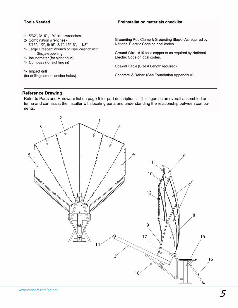
Grounding Rod Clamp & Grounding Block - As required byNational Electric Code or local codes.
Ground Wire - #10 solid copper or as required by NationalElectric Code or local codes.
Coaxial Cable (Size & Length required).
Concrete & Rebar (See Foundation Appendix A).
Preinstallation materials checklist
1- 5/32”, 3/16” , 1/4” allen wrenches2- Combination wrenches - 7/16”, 1/2”, 9/16”, 3/4”, 15/16”, 1-1/8”1- Large Crescent wrench or Pipe Wrench with
3in. jaw opening1- Inclinometer (for sighting in)1- Compass (for sighting in)
1- Impact drill(for drilling cement anchor holes)
6
Tools Needed
Reference DrawingRefer to Parts and Hardware list on page 5 for part descriptions. This figure is an overall assembled an-tenna and can assist the installer with locating parts and understanding the relationship between compo-nents.
2
12
13
11
4
1
20
18
17
19
14
56
78
910
15 16
23
24
25
8
7
9
6
10
11
12
13
14
15
12
5 4
33
17
16
18

6www.cobham.com/patriot
1. Place the King Post Mast assembly onto the foundation threaded rods and secure with nuts and washers from the foundation hardware pack. Be sure to use the 4-base reinforcement plates provided as shown. NOTE: The mast should be pointed due south (northern hemisphere sites)
2. Attach ASSY,3.8M OFFSET MAST STRUT (pt# 238307) using 5/8in hardware. Mark area on foundation for cement anchor placement location (see page 16 for foundation details and anchor requirments) NOTE: The use of an impact drill for drilling cement will be needed.
3. Assemble either the Fixed or Motorized Mount Assembly Kit option purchased with the system.
King Post Assembly Placement
7
Installation Procedure
1. Place the King Post Mast assembly onto the foundation threaded rods and secure with nuts and washers from thefoundation hardware pack. Be sure to use the 4-base reinforcement plates provided as shown.
NOTE: The mast should be pointed due south (northern hemisphere sites)
2. Attach the Mast Strut assemblies using 5/8in hardware, and 5/8in cement anchor hardware at the pad.
NOTE: The use of an impact drill for drilling cement will be needed.
3. Assemble either the Fixed or Motorized Mount Assembly Kit option purchased with the system.
See Appendix B for Fixed Mount Assembly Kit Option
See Appendix C for Motorized Mount Assembly Kit Option.
Mount Assembly
CementAnchorHardware
Base Reinforce-ment Plates (4)
PLATE, KP BASE(pt# 245000-204)
ASSY,3.8M OFFSET MAST STRUT (pt# 238307)
Area to be markedsee Pg.16 for approximent location for
anchor placement

7www.cobham.com/patriot
1. Attach 3.8m OFFSET AZ LOCK DOWN ASSEMBLY (PT# 238304) and LOCKDOWN PLATE (pt# 238304-04) to Kingpost assembly using (4) 1/2nc X 2-1/4 botls and matching washers and nuts. Leave hardware lose at this time.
2. Slide AZ LOCK DOWN ROD (pt# 238303) thru tube on lock down plate as pictured below. Leave hardware lose at this time.
3. Attach yoke end of AZ LOCK DOWN ROD to yoke using 3/4” x 2.00” shoulder bolt and 5/8” nut washers as pictured below.
4. Tighten all hardware once proper AZ angle has been set.
NOTE: All hardware mentioned above can be found in hardware bag
AZ LOCK DOWN ROD (pt# 238303)
OFFSET AZ LOCK DOWN ASSEMBLY (PT# 238304)
LOCKDOWN PLATE(pt# 238304-04)
Az Lockdown Assembly

8www.cobham.com/patriot
8
Hub Assembly
1. Place the Hub onto the A-frame using the pre-installed shoulder bolt hardware as shown.
2. Connect the Fixed or Motorized accessories per the attached Appendixs (Fixed shown)
For Fixed Mount Option- See Appendix B.
For Motorized Mount Option- See Appendix C
1. Attach ASSY,3.8M OFFSET KP ELEV.ROD (pt#238302) to yoke pick up detail using 3/4”X 2.00” shoulder bolt, 5/8 nut and washer.
2. Place 3.8M OFFSET KP ELEV.PIVOT BLOCK (pt# 238003) on to 3.8M OFFSET KP ELEV.ROD (pt#238302) as pictured below. (Leave THIS hardware loose at this time) 2. Place the HUB ASSEMBLY (pt# 238214) on to the A-frame using the pre-installed shoulder bolt hardware as shown.
3. Attach 3.8M OFFSET KP ELEV.PIVOT BLOCK (pt# 238003) to HUB ASSEMBLY using (2) 3/4nc X 1-1/2 bolts and matching lock washers.
4. Tighten all hardware at this time.
NOTE: All hardware mentioned above can be found in hardware bag
#3HP38013.
3.8M OFFSET KP ELEV.PIVOT BLOCK (pt# 238003)
3.8M OFFSET KP ELEV.ROD (pt#238302)
HUB ASSEMBLY (238214)
Hub Assembly

9www.cobham.com/patriot
1. Install TUBE,3.8M OFFSET FEED SUPPORTS (pt# 238993) using (4) 1/2nc x 7.00” bolts, matching washers and (4) FEED BOOM SHIMS (pt# 224132).
2. Tighten all Feed Support hardware.
Feed Boom Install
FEED BOOM SHIMS(PT#224132)
TUBE,3.8M OFFSET FEED SUPPORTS (pt# 238993)
This hole, closest to the edge, up.
Feed Plate Assembly Install
1. Install 3.8M OFFSET FEED PLATE ASSEMBLY (pt# 238996) using (4) 3/8nc x 3.00” bolts, washers and nuts.
NOTE: All hardware mentioned above can
be found in hardware bag #3HP38016.
NOTE:Make sure that feed booms are placed as pictured below with feed plate mounting holes up.

10www.cobham.com/patriot
Apply wax hereto aid in sliding
radial beams in to hub
Apply wax hereto aid in sliding
radial beams in to hub
1. Fasten (4) ANGLE,3.8M OFFSET HUB (pt# 238214-12) to each Radial Beam as shown, using (4) 3/8in shoulder (1) 5/16” washer, and nut per.
2. Adjust the Hub into the position shown, and select 3.8M OFFSET RADIAL BEAM C ASSEMBLY (pt#238213), and place into the outermost location inside the Hub. Fasten using 3/8in shoulder bolt hardware, (1) 5/16” washer, nut per lose. Do the same with the opposing 3.8M OFFSET RADIAL BEAM C ASSEMBLY (pt#238213).
NOTE: Hard to reach hardware can be accessed by reaching inside and around the end of the Radial Beam to reach the back side.
3. Repeat step 2 for 3.8M OFFSET RADIAL BEAM B ASSEMBLY (pt# 238211) 3.8M OFFSET RADIAL BEAM A ASSEMBLY (pt# 238210)
4. Tighten all Radial Beam hardware in steps 1 through 3.
ANGLE,3.8M OFFSET HUB(238214-12)
RADIAL BEAM ASSEMBLY
NOTE: Shoulder bolts are fastened from the inside of the Hub with the washers and nuts
on the outside. All hardware can be found in bag
#3HP38011
Radial Beam Install

11www.cobham.com/patriot
1. Pre-assemble all (20) BRKT.,3.8M OFFSET BACK SUPPORT to the Radial Beams using 1/2x1-1/4” bolt, 2-washers, 1-nut. Leave loose.2. Attach 3.8M OFFSET 65” BACK SUPPORT L (pt# 238224) and 3.8M OFFSET 90” BACK SUPPORT (pt# 238223)3. Starting in the middle and working outward attach (6) ANGLE,3.8M 32” BACK SUPPORT (pt# 238220) and (4)ANGLE,3.8M 45”BACK SUPPORT using 1/2x1-1/4” bolt, 2-washers, 1-nut.4. Attach (2)ASSY,3.8M OFFSET 90” BACK SUPPORT (pt# 238223) to the Hub and Radial Beams as shown.
NOTE: Leave all Frame hardware loose at this time.NOTE: Assure that all supports angles and frame angles are parallel to to face of the Hub.
238223ASSY,3.8M OFFSET 90”
BACK SUPPORT
238223ASSY,3.8M OFFSET 90”
BACK SUPPORT
238220ANGLE,3.8M 32” BACK
SUPPORT
238220ANGLE,3.8M 32” BACK
SUPPORT
238220ANGLE,3.8M 32” BACK
SUPPORT
238220ANGLE,3.8M 32” BACK
SUPPORT
238219ANGLE,3.8M 45”BACK
SUPPORT
238219ANGLE,3.8M 45”BACK
SUPPORT
238224ASSY,3.8M OFFSET 65”
BACK SUPPORT L
238225ASSY,3.8M OFFSET 65”
BACK SUPPORT R
238222BRKT.,3.8M OFFSET
BACK SUPPORT
Back Structure Install
NOTE: All hardware mentioned above can be found in hardware bag
#3HP38011-03

12www.cobham.com/patriot
1 Starting with ASSY,3.8M OFFSET C-LEFT PANEL (pt# 238208) Place the panel into place onto the left-most radial ream as pictured below Fasten with 1/4x1/2 truss head bolts. Leave bolts 1/2 turn loose at this time.
2 Fasten the next panel as mentioned above. Continue untill all panels have been placed. (See inset picture for panel placement)
3 Tighten all hardware at this time. See note bellow for tightening procedure(If you must step into reflector please DO NOT step in center of panels. Keep weight in radial beams ONLY)
NOTE:Left and right orentation are as you are standing BEHIND the reflector assembly. The above drawing is pictured as you are standing INFRONT of the reflector assembly. Left and right designated panels are NOT interchangeable. All above mentioned hardware can be found in hardware bag 3HP38011-01
ASSY,3.8M OFFSET C-LEFT PANEL
(pt# 238208)
Panel Install
Tighten first two rows of hardware on each panel start-
ing here. Then proceed to next two rows on each panel. Continue this pattern untill all
screws are tight.

13www.cobham.com/patriot
1. Attach Kurffing Segiments to outter most part of panels as pictured below using same 1/4-20 screws used on panels
2. When all panel, kurffing and hardware is in place tighten all panel and back structure angle bolts starting near the hub and working outward.
ASSEM, CURFING 46.79” “A”(238911)
ASSEM, CURFING 57.00” “C”
(238912)
ASSEM, CURFING 42.68” “B”(238910)
Kurfing Install

14www.cobham.com/patriot16
Antenna Pointing
NOTE: The Reflector contains a 23 degree offset look angle. Therefore, when the face of the reflector looks perpendicularto the ground, the antenna is actually looking 23 degrees in elevation.The antenna look angle is actually the top side of the Feed Support Plates as shown below.
FOR FIXED MOUNT POINTING-.1. Adjust the reflector up or down in elevation by turning the two 2” hex nuts on the Elevation Rod Assembly until thedesired elevation is measured (taking Elevation angle measurement from the Feed Support Arms).
4. Patriot recommends the use of cross pol nulling using a spec-trum analyzer during TX/RX installations. After tightening theazimuth and elevation hardware, peak the co-pol signal usingthe spectrum analyzer. Then rotate the feed assemble roughly90 degrees to obtain a cross pol null. Fine tune the null. Thescale on the feed horn can be used with the tick mark on feedholder top or the seam between feed holder top and bottom. Thetick mark and seam are 90 deg. apart.Note that changes may benecessary to the resolution and video bandwidth to bring thesignal above the noise floor. Note the angle of optimum crosspol null. Rotate the feed back exactly 90 degrees and tighten thefeed clamp.
2. Azimuth Adjustment: With the electronics set to acquire the satellite, use the double-nut threaded adjustment on theAzimuth Rod.
NOTE: If signal is not found on first pass of Azimuth, adjust elevation up or down in 2 deg increments until signal is found.
3. Peak the satellite signal by fine adjustments made in both azimuthand elevation until the optimum signal is achieved.
Note: Adjust, tighten, recheck until optimum signal is reached inboth Azimuth and Elevation.
Inclinometer
FocalAxis

15www.cobham.com/patriot
16www.cobham.com/patriot
150
SQ
182" M
AX
A
AN
CHO
R ST
UDS
& HD
WE
INC
LUDE
D w
/AN
TEN
NA
. SE
CUR
E US
ING
CHE
MIC
AL
ADH
ESIV
E; H
ILTI
P/N
283
548
REC
OM
MEN
DED.
2
9.50
CEN
TTY
P
66
12.6
APP
ROX
TYP
66
28.4
APP
ROX1
(FRO
NT O
F A
NTE
NN
A)
(2X)
Ø1-
1/16
DRI
LL ~
8" D
P,
TRA
NSF
ER L
OC
ATIO
N A
T ASS
'YFR
OM
SUP
PORT
STR
UTS.
ADD
(4) 1
12" R
E-BA
RS(2
EA
CH
WA
Y) A
S SH
OW
NTO
TOP
LAYE
R
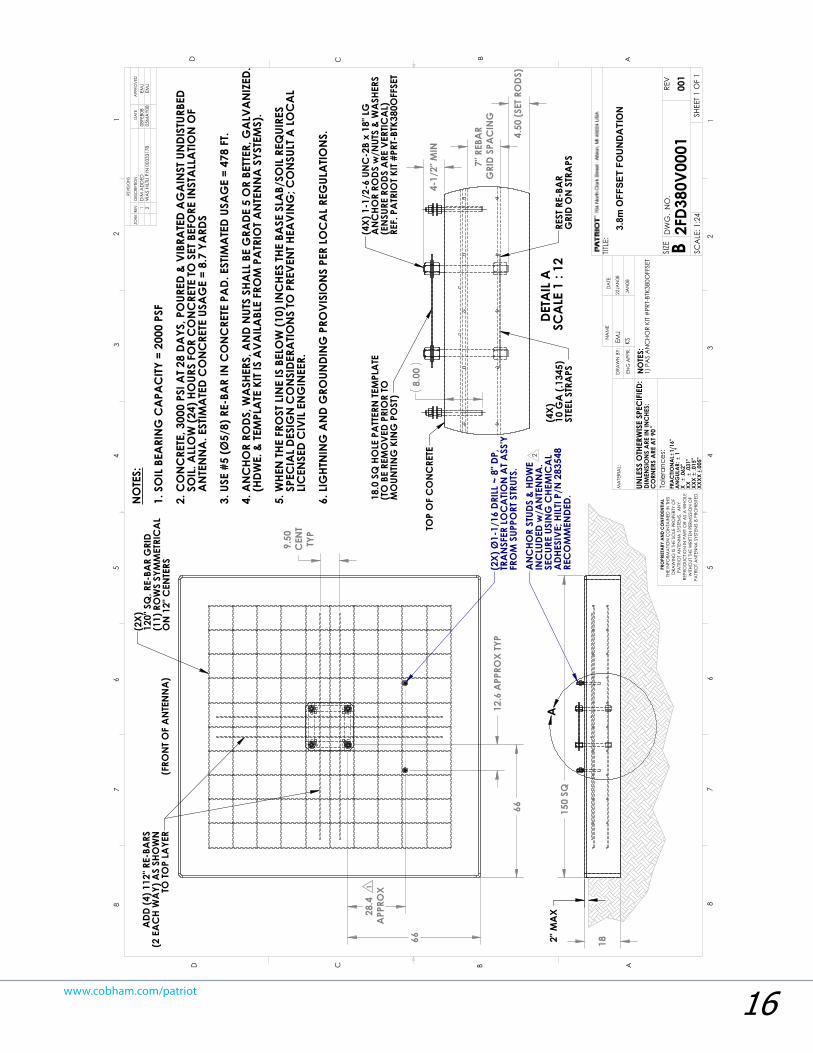
NO
TES:
1. S
OIL
BEA
RIN
G C
APA
CITY
= 2
000
PSF
2. C
ON
CRE
TE, 3
000
PSI A
T 28
DAYS
, PO
URED
& V
IBRA
TED
AG
AIN
ST U
NDI
STUR
BED
S
OIL
. ALL
OW
(24)
HO
URS
FOR
CO
NC
RETE
TO S
ET B
EFO
RE IN
STA
LLA
TION
OF
A
NTE
NN
A. E
STIM
ATE
D C
ON
CRE
TE U
SAG
E =
8.7
YARD
S
3. U
SE #
5 (Ø
5/8)
RE-
BAR
IN C
ON
CRE
TE P
AD.
EST
IMA
TED
USA
GE
= 47
8 FT
.
4. A
NC
HOR
RODS
, WA
SHER
S, A
ND
NUT
S SH
ALL
BE
GRA
DE 5
OR
BETT
ER, G
ALV
AN
IZED
.
(H
DWE.
& TE
MPL
ATE
KIT
IS A
VAIL
ABL
E FR
OM
PA
TRIO
T AN
TEN
NA
SYS
TEM
S).
5. W
HEN
THE
FRO
ST L
INE
IS B
ELO
W (1
0) IN
CHE
S TH
E BA
SE S
LAB/
SOIL
REQ
UIRE
S
SPE
CIA
L DE
SIG
N C
ON
SIDE
RATIO
NS
TO P
REVE
NT H
EAVI
NG
; CO
NSU
LT A
LO
CA
L
LIC
ENSE
D C
IVIL
EN
GIN
EER.
6. L
IGHT
NIN
G A
ND
GRO
UNDI
NG
PRO
VISI
ON
S PE
R LO
CA
L RE
GUL
ATIO
NS.
(2X)
12
0" S
Q. R
E-BA
R G
RID
(11)
RO
WS
SYM
MET
RIC
AL
ON
12"
CEN
TERS
4-1/
2" M
IN
4.50
(SET
RO
DS)
8.00
7" R
EBA
RG
RID
SPA
CIN
G
DETA
IL A
SC
ALE
1 :
12
TOP
OF
CO
NC
RETE
18.0
SQ
HO
LE P
ATT
ERN
TEM
PLA
TE
(TO
BE
REM
OVE
D PR
IOR
TO
MO
UNTIN
G K
ING
PO
ST)
(4X)
10
GA
(.13
45)
STEE
L ST
RAPS
REST
RE-
BAR
GRI
D O
N S
TRA
PS
(4X)
1-1
/2-6
UN
C-2
B x
18" L
G
AN
CHO
R RO
DS w
/NUT
S &
WA
SHER
S(E
NSU
RE R
ODS
ARE
VER
TICA
L)RE
F. P
ATR
IOT K
IT #P
RT-B
TK38
0OFF
SET
08FE
B08
1D
IM A
DD
EDEM
J2
EMJ
WA
S HI
LTLI
P/N
003
3317
805
MA
Y08
D C B AABCD
12
34
56
788
76
54
32
1
THE
INFO
RMA
TION
CO
NTA
INED
IN T
HIS
DRA
WIN
G IS
THE
SO
LE P
ROPE
RTY
OF
PATR
IOT
AN
TEN
NA
SYS
TEM
S. A
NY
REPR
OD
UCTIO
N IN
PA
RT O
R A
S A
WHO
LEW
ITHO
UT T
HE W
RITT
EN P
ERM
ISSI
ON
OF
PATR
IOT
AN
TEN
NA
SYS
TEM
S IS
PRO
HIBI
TED
.
PRO
PRIE
TARY
AN
D C
ON
FIDE
NTIA
L
FRA
CTIO
NA
L1/
16"
AN
GUL
AR:
1
X
.062
"XX
.0
31"
XXX
.015
" XX
XX.0
05"
DRA
WN
BY:
ENG
APP
R.
NO
TES:
DA
TEN
AM
ETIT
LE:
SIZE B
DW
G.
NO
.RE
V
SCA
LE: 1
:24
UNLE
SS O
THER
WIS
E SP
ECIF
IED:
SHEE
T 1 O
F 1
REVI
SIO
NS
DES
CRI
PTIO
NRE
V.D
ATE
APP
ROV
EDZO
NE
EMJ
22JA
N08
KSJA
N08
001
2FD3
80V0
001
3.8m
OFF
SET
FOU
ND
ATI
ON
MA
TERI
AL:
1) P
AS
AN
CHO
R KI
T #
PRT-
BTK3
80O
FFSE
T
Tole
ranc
es:
DIM
ENSI
ON
S A
RE IN
INC
HES:
CO
RNER
S A
RE A
T 90

17www.cobham.com/patriot
1. Assemble the Elevation Jack assembly tothe Hub assy as shown using 2- 3/4x2-1/2”shoulder bolts, 2- 3/4” washers(bolt side), 2-5/8” washers (nut side), and 2- 5/8” nyloknuts.
2. Assemble the Jack extension rod to theYoke assy using 1- 3.4x4” bolt, 2 washers,and nylok nut.
Mototized Mount Option Assembly
Appendix C
3. Mount the Azimuth GearDrive to theKingPost Mast assembly using 4- 3/8x1-1/2”bolts and washers.
4. Assemble the keyed drive sprocket, keyand guide bushing to the drive shapft asshown. Leave loose to adjust height later.
Drive Gear238310
Actuator AdaptorPlate
238306 (2)
Appendix B

18www.cobham.com/patriot
5. Place the D-Ring assy onto the mastand yoke assy’s as shown. Use the“Resolver Shoulder Bolt assy” for the D-ring-Yoke assy pivot.
6. Assemble the D-Ring to the Yokeusing 2- 1/2x1-1/2” Flat Socket Headbolts, 2 washers, and 2 nylok nuts.
Mototized Mount Option Assembly
Appendix C(continued)
1/2x1-1/2”Counter SunkSocket Head
Bolt
D-Ringattachment
plate
7. Replace the right Hub connection shoulder boltwith a “Resolver Shoulder Bolt assy”.
8. Wrap the chain assyin place around the D-Ringand drive sprocket attaching the chain tensionerblocks to the yoke with 2- 5/8x1-1/2” NF bolts andwashers,NOTE: Apply lock-tite thread compound to thethreads of these fasteners.
9. Line up the 2 Idler sprockets and Idler plate.Using 4- 5/8x4” bolts, 2 washers, and nylok nutsassemble the Idler plate as shown.
10. Adjust the chain tension purposely leaving asmall amount of slack. Each adjuster bolt andchain tensioner block should have an equal gap toone another.
Spacer Tubes20000054 (2)
Idler plate238309
ChainTensioner
Bolts
Idler gear238311 (2)
Elevation encoderbolt assem
238243Azmuth encoderbolt assem
238234
Appendix B

19www.cobham.com/patriot
11. Mount Elevation Limit Switch and bracket, as shown, to yoke cross tube
12. Mount Azmuth Limit Switch to bracket as done in previous step. Mount bracket to King Post MAst as shown.
Mototized Mount Option Assembly
Appendix C(continued)
Trip Blocks, 238239 (4)Approx. Range
of Motion
Yoke Cross Tube
Kingpost Mast
13 Assemble the Adjustable Limit stop plates to the spacer blocks and rough adjust a range of motion as shown.
Spacer Block238241
Spacer Block,238241, mountedto underside of Hub
14. Connect the wiring per instrucitons of the selected controller unit.
NOTE: The Azimuth range of motion can be adjusted to any desiredrange within its’ 180deg capability. Just be certain to trip the switchbefore the Yoke bumps the Mast assembly.
1/4-20x .75”Hardware
Hub
Limit Switch Bracket20000038 (2)
Limit Switch Cutoff Plate
20000039 (2)Adaptor Bracket
238242
Appendix B

20www.cobham.com/patriot
15. Assemble the Drive motors to the Elevation acutator and the Azimuth Gearbox.
Mototized Mount Option Assembly
Appendix C(continued)
Recommended Maintenance Schedule
Maintenance Item CommentCheck Azimuth gearbox oil level. Oil level should be even with fill plug. Add oil as required to maintain proper level
Check Azimuth chain and sprockets for dirt. Clean and lubricateas needed. Lubricate with good commercial quality spray lubricant
Check Elevation gearbox oil level. Oil level should be evenwith fill plug. Add oil as required to maintain proper level.
Check Elevation Jack boot for damage or deterioration. Clean dirt and oil from boot as required. Use soap and water for cleaning
Check cables and connectors for damage or deterioration.Clean as required to prolong life. Use electrical contact cleaner as required
Check wiring for strain relief, damage or deterioration.Clean as required to prolong life.
Troubleshooting
Troubleshooting Tips
Item Symptom Recommended Action1 Antenna will not drive. Check for mechanical interference
Check power sourceCheck fuses in drive cabinetCheck limit switch status/operationRefer to controller maintenance manual for further options
2 Feed polarization will not drive. Check for mechanical interferenceCheck power sourceCheck fuses in drive cabinetCheck limit switch status/operationRefer to controller maintenance manual for further options
3 Low signal strength Check pointing of antenna and re-peak as required if mis-pointedCheck feed assy for damage or water ingressCheck waveguide for damage or water ingressCheck cables for damage or poor connections
Appendix B


ANTENNA SYSTEMS
704 North Clark StreetAlbion, MI 49224 USA
Tel: (517)629-5990Fax: (517)629-6690
E-mail: [email protected] site: www.sepatriot.com
Specifications
Mechanical
Antenna Size 3.8m (150”)Offset Angle 22.9 degreesF/D 0.64Operational Wind 50 m.p.h.Survival Wind 125 m.p.h.Operational Temp -40 to 140 FSurvival Temp -60 to 180 FRain Operational = 1/2in./hr
Survival = 3in./hrIce 1 in. Radial -or-
1/2 in. + 60 m.p.h. wind
Rev-01-05-06
Electrical
Tx Band(GHz)Rx Band(GHz)Tx Gain dBi (Midband)Rx Gain dBi (Midband)EfficiencyCross Polarization (on axis)
Side Lobes
(note- Feed dependent 17.7 or 27.3dB )
C BandLinear Circular
Ku Band
5.85 - 6.725 5.85 - 6.425 3.4 - 4.2 3.625 - 4.2 46.2 46.1 42.1 41.9
70% 35dB (see note)
ITU-580-5
13.75 - 14.510.7 - 12.75 53.5 51.8 70% 35dB
Cobham SATCOM Land SystemsPatriot Antenna Products 704 North Clark StreetAlbion, Michigan 49224 USATel: (01) 517 629 5990 Fax: (01) 517 629 6690 [email protected]