38dlplus training power point
TRANSCRIPT

Model 38DL PLUSOperation TrainingOperation Training

IndexClick on the links below to go directly to the corresponding slide (Please Note: youClick on the links below to go directly to the corresponding slide. (Please Note: you have to be in slide show mode for the links to work.)
Power UpDo-ZERO-Standard Dual TransducersDo-ZERO for THRU-COAT Transducers
38DLP Echo-to-Echo FeatureAuto Echo-to-Echo, Dual Element
Transducers
ID ReviewGrid ViewCreating Notes
Selecting Units and ResolutionMain Screen38DLP Standard Calibration38DLP THRU-COAT Calibration
Directly Enter Velocity, THRU-COAT Mode
Manual Echo-to-Echo, Dual Element TransducersTemperature Compensation Feature38DLP Min/Average Setup38DLP B-Scan ModeAdditional Gage Features
gNote Copy
38DLP Sending, Printing and Deleting data
Sending a File or Multiple FilesSending/Printing a Range of a FileDeleting FilesMode
THRU-COAT Measurement Screen38DLP Single Element Transducer Calibration
Single Element Transducer SelectionSingle Element Cal Vel/Cal Zero
Additional Gage Features38DLP Datalogger
Selectable Text Editing ModesDatalogger MemoryFile OpenFile Create
Deleting FilesFile CopyFile Edit Rename (Non Grid Files)File Edit Rename (Grid and Boiler Files)File Reports
38DLP Setup MenuCalibration Lock
38DLP Instrument Lock with Programmable Password38DLP EMAT Transducer38DLP Waveform Controls
A Scan Range Adjust
Incremental FileSequential FileSequential File with Custom Points2D Grid File (Standard)2D Grid File (EPRI Format)2D G id Fil ith C t P i t
pSetup MenuMeasurement SetupCommunication SetupDisplay Setup
38DLP SP MenuA-Scan Range AdjustDelay AdjustEcho Detection w/Dual Element
TransducersFreeze ModeZoom
2D Grid File with Custom Points3D Grid FileBoiler FileID# Entry/EditSaving Thickness/WaveformsInsert/Append ID# Into a File
38DLP Single Element Transducer Setup38DLP Custom Dual Element Transducer Setups38DLP Velocity and Time of Flight Measurements38DLP Software Options
Display Brightness AdjustManual Gain Adjust Dual Element
Extended Blank for Dual Element
Insert/Append ID# Into a File p

Power UpPower UpPower UpPower UpThe On/Off key is used to turn the 38DL PLUS on and off.ON
OFF
Back toIndex

Model 38DL PLUSModel 38DL PLUSDual Element Do-ZERO
Back toIndex

Do-ZERO for Standard Dual TransducersDo-ZERO for Standard Dual TransducersDo-ZERO for Standard Dual TransducersDo-ZERO for Standard Dual Transducers
Uncouple the transducer and make sure the tip is free of any couplant
“Do-ZERO” allows the gage to recognize th t d f ti l t It ill l
Press
sure the tip is free of any couplant layer.
the transducer for optimal setup. It will also measures the time of flight through the transducer to compensate for transducer wear and changes in temperature.Press wear and changes in temperature.
then2nd FDo-ZERO
CALZERO
Note: The [2nd F], [Zero] can be pressed any time the transducer is
Rx Tx
p yuncoupled to update the Zero offset.
RxDelay
TxDelay
Back toIndex

Do-ZERO for THRU-COAT TransducersUncouple the transducer and make sure the tip is free of any couplant layer
“Do-ZERO” allows the gage to recognize the transducer for optimal setup. It will also layer. p pmeasures the time of flight through the transducer to compensate for transducer wear and changes in temperature.
Press: th2nd FDo-ZERO
CALPress: then2nd F CALZERO
Use [ ], [ ] to turn THRU-COAT On or Off, Press [Enter]P [E t ] “OK” t l t th D ZERO
Rx TxNote: The [Zero] can be pressed at any time the transducer is
Press [Enter] on “OK” to complete the Do-ZERO
RxDelay
TxDelayuncoupled to update the Zero offset or to turn THRU-COAT On
or Off. Back toIndex

Selecting Measurement Units and ResolutionSelecting Measurement Units and ResolutionAllows the user to set Measurement Units and Resolution
Press:SP MENU
SETUPMENU
Use [ ] [ ] to highlight theUse [ ],[ ] to highlight the Measurement setup then press [ENTER] Use [ ],[ ] to select “units” or “resolution”
and [ ],[ ] to change the setting, thenand [ ],[ ] to change the setting, then press [Meas]
Back toIndex

Main ScreenMain ScreenMain ScreenMain Screen
Back toIndex

Model 38DL PLUSCalibration Standard Dual Transducers
Back toIndex

Standard Dual Element Cal VelocityStandard Dual Element Cal VelocityStandard Dual Element Cal VelocityStandard Dual Element Cal Velocity
Couple transducer to the thick sample press: Allows the user to calibrate for thesample press: Allows the user to calibrate for the
speed of sound of the material to be tested. Usually done on a sample representing the maximum of the
t
VEL
CALVEL
measurement range.
Once reading is steady press:
Uncouple the transducer and
ENTER
Uncouple the transducer and enter the known thickness
Back toIndex
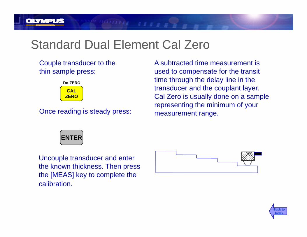
Standard Dual Element Cal ZeroStandard Dual Element Cal ZeroStandard Dual Element Cal ZeroStandard Dual Element Cal ZeroA subtracted time measurement is used to compensate for the transit
Couple transducer to the thin sample press: used o co pe sa e o e a s
time through the delay line in the transducer and the couplant layer. Cal Zero is usually done on a sample representing the minimum of your
sa p e p essDo-ZERO
CALZERO
representing the minimum of your measurement range.Once reading is steady press:
Uncouple transducer and enter
ENTER
the known thickness. Then press the [MEAS] key to complete the calibration.
Back toIndex

Model 38DL PLUSTHRU-COAT Calibration
Back toIndex

THRU-COAT Cal VelocityTHRU-COAT Cal VelocityyyCouple transducer to the thicksample press: Allows the user to calibrate for theAllows the user to calibrate for the
speed of sound of the material to be tested. Usually done on a sample representing the maximum of the
t
VEL
CALVEL
measurement range.
Once the reading is steady press:
Uncouple the transducer and
ENTER
Uncouple the transducer and enter the known thickness
Back toIndex

THRU-COAT Cal ZeroTHRU-COAT Cal ZeroTHRU COAT Cal ZeroTHRU COAT Cal Zero
A subtracted time measurement used to compensate for the transit time
Couple transducer to the thin sample press: o co pe sa e o e a s e
through the delay line in the transducer and the couplant layer. Cal Zero is usually done on a sample representing the minimum of your
sa p e p essDo-ZERO
CALZERO
representing the minimum of your measurement range.Once reading is steady press:
ENTER
Uncouple transducer and enter
ENTER
the known thickness. Press the [Meas] key to complete the calibration or press the [CAL VEL] key to calibrate for the velocity ofkey to calibrate for the velocity of the coating.
Back toIndex
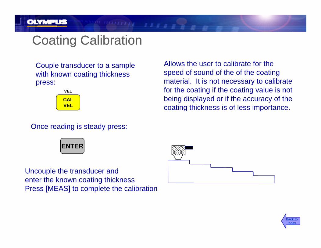
Coating CalibrationCoating Calibrationgg
Couple transducer to a sample with known coating thickness
Allows the user to calibrate for the speed of sound of the of the coating g
press: material. It is not necessary to calibrate for the coating if the coating value is not being displayed or if the accuracy of the coating thickness is of less importance
VEL
CALVEL coating thickness is of less importance.
Once reading is steady press:
Uncouple the transducer and
ENTER
Uncouple the transducer and enter the known coating thicknessPress [MEAS] to complete the calibration
Back toIndex

Directly enter the velocity in THRU-COAT ModeDirectly enter the velocity in THRU-COAT ModeAllows the user to directly enter the velocity of the material to be tested. When using THRU-COAT the velocity of the coating can
Press
2nd F
VEL
CALVELthen y g
also be entered.
The current velocity will bedisplayed Use the arrow keys
VEL
displayed. Use the arrow keysto enter the know velocity. Thenpress [MEAS]
Press
again2nd F
VEL
CALVELthen
The current coating velocity will bedisplayed. Use the arrow keysto enter the know velocity. Thento enter the know velocity. Thenpress [MEAS]
Back toIndex

THRU-COAT Measurement ScreenTHRU-COAT Measurement Screen
CoatingThickness
Metal ThicknessMetal Thickness
Back toIndex

Model 38DL PLUSCalibration of Single Element Transducers
Back toIndex
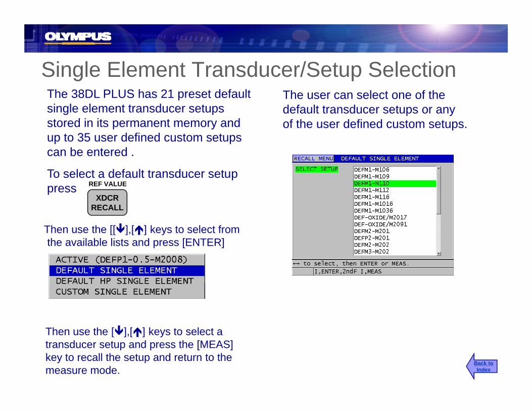
Single Element Transducer/Setup SelectionSingle Element Transducer/Setup SelectionThe 38DL PLUS has 21 preset default single element transducer setups stored in its permanent memory and
The user can select one of the default transducer setups or any of the user defined custom setups.p y
up to 35 user defined custom setups can be entered .
To select a default transducer setup
of the user defined custom setups.
ppress REF VALUE
XDCRRECALL
Then use the [[ ] [ ] keys to select fromThen use the [[ ],[ ] keys to select from the available lists and press [ENTER]
Then use the [ ],[ ] keys to select a
Back toIndex
e use e [ ],[ ] eys o se ec atransducer setup and press the [MEAS] key to recall the setup and return to the measure mode.

Single Element Cal VelocitySingle Element Cal Velocityg yg yCouple transducer to the thick sample
and press: Allows the user to calibrate for the speed of sound of the material to be tested Usually done on a sampletested. Usually done on a sample representing the maximum of the measurement range.
VEL
CALVEL
Once reading is steady press:
ENTER
Uncouple the transducer and enter the known thickness use in the [ , , ] keys
Back toIndex

Single Element Cal ZeroSingle Element Cal ZeroSingle Element Cal ZeroSingle Element Cal ZeroA subtracted time measurement used to compensate for the transit time through the delay line in the
Couple transducer to the thin sample press:
through the delay line in the transducer and the couplant layer. Cal Zero is usually done on a sample representing the minimum of your
Do-ZERO
CALZERO
measurement range.Once reading is steady press:
ENTER
Uncouple the transducer and enter the known thickness use in the [ , , ] keys
Back toIndex

Model 38DL PLUSI t t L k ith P blInstrument Lock with Programmable
Password
Back toIndex

Instrument Lock with Programmable PasswordInstrument Lock with Programmable PasswordInstrument Lock with Programmable PasswordInstrument Lock with Programmable PasswordThe instrument lock on the 38DL PLUS allows the user to lock advanced features and functions so that they are notand functions so that they are not accidently altered or changed.
A password can be set so that the locked functions can not be unlocked withoutfunctions can not be unlocked without knowing the password
The following functions can be locked
•Calibration•Access to Setup Menu and SP Menu•Transducer Recall•Datalogger (except for the save key)N t If th f t th d •Datalogger (except for the save key)•The ability to adjust the gain•Waveform adjustment parameters
Note: If the user forgets the password please contact Olympus for the master password.
Back toIndex

Instrument Lock setting a PasswordInstrument Lock setting a PasswordInstrument Lock, setting a PasswordInstrument Lock, setting a Password
PressSetting a password is an optional feature and the 38DL PLUS can be locked with out a password
SP MENU
SETUPMENU a password.
Then use the [[ ],[ ] keys to selectPassword Set and press [ENTER]
Use the editing functions to enter a password
Note: If the user forgets the password l t t Ol f th t
Use the editing functions to enter a password and press [Enter] use the [ , ]keys to select set and press [ENTER].
Back toIndex
please contact Olympus for the master password.

Instrument Lock with without PasswordInstrument Lock with without PasswordInstrument Lock with without PasswordInstrument Lock with without Password
PressIf a password has been set then the password must be entered in the Instrument Lock screen before any of the functions can be used. If a
SP MENU
SETUPMENU before any of the functions can be used. If a
password has not been set then the password area will be grayed out.
Then use the [ ],[ ] keys to selectInstrument Lock and press [ENTER]
Use the editing functions to enter a password and press [Enter] use [ ],[ ] keys to select the a function to lock and [ , ] lock and unlock
Back toIndex
it. Highlight set and press [ENTER] to activate the lock

Example of a locked functionExample of a locked functionpp
Wave Adjust On: Key locked!
Back toIndex
Wave Adjust On: Key locked!

Model 38DL PLUSUsing the EMAT Transducer
Back toIndex

EMAT TransducerEMAT TransducerAn EMAT (Electro Magnetic Acoustic Transducer) uses the Magnetostrictive principle to generate shear wave sound energy in ferrous metals thatshear wave sound energy in ferrous metals that are externally coated with high temperature oxide scale.
The EMAT transducer does not require the use of ultrasonic couplant. If the scale is not fully bonded to the surface of the steel, the shear wave sound energy will not be transmitted into the metal
E110-S
B
energy will not be transmitted into the metal.
Back toIndex

EMAT TransducerEMAT Transducer
•EMAT transducers are designed to be a quick way of d t i i th i t ll thi k ith tdetermining the approximate wall thickness without removing the external oxide scale.
•The E110-SB EMAT transducers generate shear sound e 0 S t a sduce s ge e ate s ea sou dwaves in the steel material.
•The EMAT transducers create a non-focused signal and is designed to give a good estimate of the remaining wallis designed to give a good estimate of the remaining wall thickness (+/-0.010 in or +/-0.25 mm)
•EMAT transducers are relatively insensitive to small yinternal pits.
•The minimum capability is approximately 0.080 in. (2 0mm)(2.0mm)
Back toIndex

Connecting the E110 SB EMAT TransducerConnecting the E110-SB EMAT Transducer
The 1/2XA/E110 filter adapter must be l d i t th t d t
LCB-74-4
38DL PLUS
plugged in to the transducer connectors located at the top of the 38DL PLUS. The E110-SB can then be connected to the 1/2XA/E110 adapter box using a standard
E110-SB
38DL PLUS 1/2XA/E110 adapter box using a standard Lemo to BNC cable. (LCB-74-4)
The 38DL PLUS will automatically recall the default setup for the E110-SB (EMAT) transducer when the Adapter and E110-SB pis plugged in. The gage is now ready to take thickness measurements of steel that is coated with external scale using the default setupdefault setup.
Back toIndex
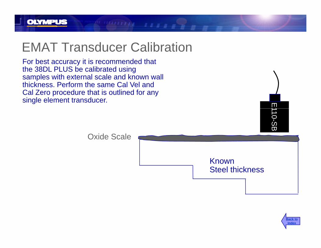
EMAT Transducer CalibrationEMAT Transducer CalibrationFor best accuracy it is recommended that the 38DL PLUS be calibrated using samples with external scale and known wallsamples with external scale and known wall thickness. Perform the same Cal Vel and Cal Zero procedure that is outlined for any single element transducer. E
1
Oxide Scale
110-SB
Known Steel thicknessSteel thickness
Back toIndex

Using Gain with the EMAT TransducergWhen using the EMAT transducer it will often be necessary to adjust the gain level in order to make proper echo detection. This is due to the variation in signal amplitude caused by changes in the external oxide thickness and surface conditions.
PressGAIN
then Use the [ ],[ ] keys to adjust the Gain Value
Gain too low echo not detected
Gain set properly set for echo detection Back to
Index

Waveform ControlsWaveform ControlsWaveform ControlsWaveform Controls
A Scan Range Adj st Zoom Mode• A-Scan Range Adjust
• Delay Adjust
• Echo Detection for Dual
• Zoom Mode
• Display Brightness Adjust
• Manual Gain Adjust for DualEcho Detection for Dual Transducers
• Freeze Mode
Manual Gain Adjust for Dual Transducers
• Extended Blank for Dual Transducers
Back toIndex

A-Scan Range AdjustA-Scan Range Adjustg jg j
PressAllows the operator to cycle through the fixed ranges of the waveform display. The range should be set so that the
DELAY
RANGE
echo from your thickest material will be on screen.Successive presses of the [RANGE]
key toggles through the different ranges.
Note: Adjusting the range will not affect calibration. There are fi d di l f h t d t d difixed display ranges for each transducer type depending on transducer frequency.
Back toIndex

Delay Adjusty j
Press The delay function is used to adjust the beginning (left side) of the waveform. DELAY
then The user can delay a portion of the signal off screen so they can view the important part of the waveform in greater detail.
2nd F RANGE
Th th [ ] [ ] T dj t greater detail.Then use the [ ],[ ] To adjustthe waveform delay
Delay
Back toIndex

Echo Detection with Dual Element TransducersEcho Detection with Dual Element TransducersEcho Detection with Dual Element TransducersEcho Detection with Dual Element Transducers
Echoes must be greater in amplitude than 20% of screenamplitude than 20% of screen height in order to be detected.20%
Echo not detected
Note: The detection threshold is not the measurement point. Measurements are made usingMeasurements are made using Algorithms and DSP and are independent of amplitude.
20%
Echo detected Back toIndex

Freeze ModeFreeze ModeFreeze ModeFreeze ModePress: Freeze allows the user to freeze both
the waveform and thickness display, th [FREEZE] k i d
FREEZE
once the [FREEZE] key is pressed. The display can be reset by pressing the [FREEZE] key again or by pressing the [SAVE] or [MEAS] keys.Press [FREEZE] again to [ ] [ ] yPress [FREEZE] again to
return to a live measurement display.
Note: The Freeze function is useful for high temperature applications. This f ti b d t li it th t d t t ti d tfunction can be used to limit the transducer contact time and prevent overheating the transducer. Freeze is also used in conjunction with Min/Max mode to prevent capturing false couplant readings.
Back toIndex

Zoom, Single and Dual Element, Mode 1
PressZoom centers the measured echo on the waveform display. The Zoom will
E-TO-E
ZOOM
Zoom, Single and Dual Element, Mode 1
automatically track the measured echo and assure that it remains in the center 60% of the screen.
Press [ZOOM] again to returnPress [ZOOM] again to return to the previously set range.
Zoomed WaveformBack toIndex
Un-Zoomed Waveform
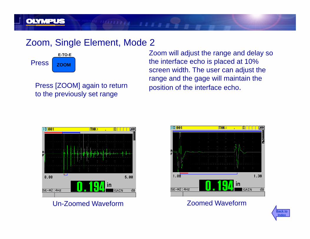
Zoom Single Element Mode 2Zoom will adjust the range and delay so the interface echo is placed at 10% screen width. The user can adjust the
E-TO-E
ZOOMPress
Zoom, Single Element, Mode 2
range and the gage will maintain the position of the interface echo.Press [ZOOM] again to return
to the previously set range
Zoomed WaveformUn-Zoomed WaveformBack toIndex
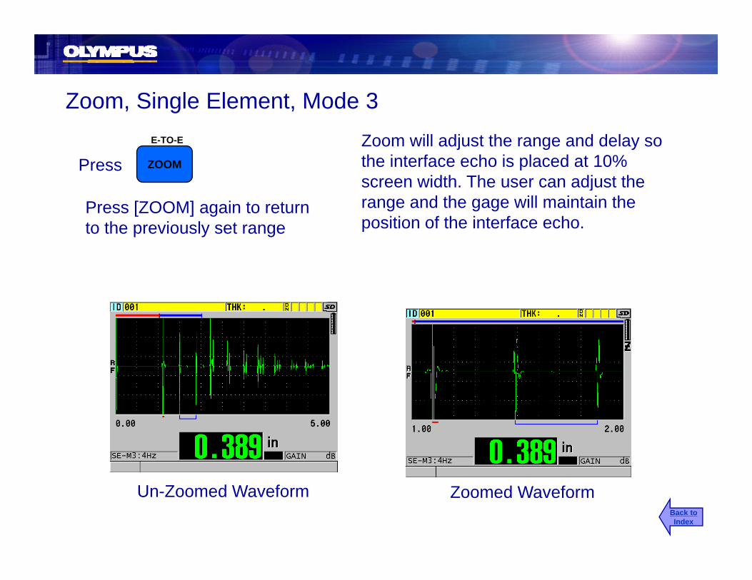
Zoom, Single Element, Mode 3Zoom will adjust the range and delay so the interface echo is placed at 10% screen width The user can adjust the
E-TO-E
ZOOMPress
Zoom, Single Element, Mode 3
Press [ZOOM] again to return to the previously set range
screen width. The user can adjust the range and the gage will maintain the position of the interface echo.
Zoomed WaveformUn-Zoomed WaveformBack toIndex

Display Brightness AdjustDisplay Brightness AdjustDisplay Brightness AdjustDisplay Brightness AdjustPress Allows the user to adjust the contrast of
the display for optimum viewing in any DISPLAY
lighting condition.Use [ ],[ ] [ ],[ ] to highlightDisplay Brightness
Then use [ ],[ ] To select between0 25 50 75 d 100%0, 25, 50, 75 and 100%
Note: Higher display brightness settings will decrease battery life battery: 4Hz and 0% brightness is 16 hours4Hz and 0% brightness is 16 hours
4Hz and 100% 12.5 hoursBack toIndex
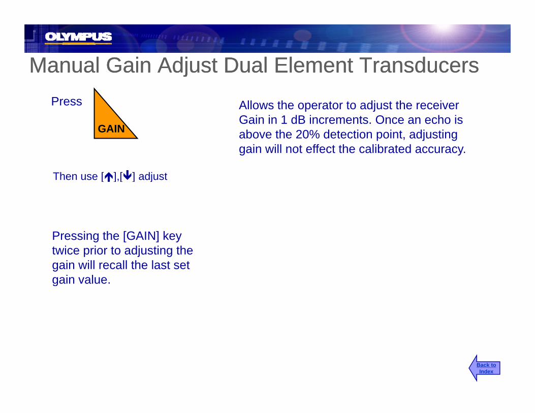
Manual Gain Adjust Dual Element TransducersManual Gain Adjust Dual Element TransducersjjPress Allows the operator to adjust the receiver
Gain in 1 dB increments. Once an echo is GAIN above the 20% detection point, adjusting
gain will not effect the calibrated accuracy.
GAIN
Then use [ ],[ ] adjust
P i th [GAIN] k
[ ],[ ] j
Pressing the [GAIN] key twice prior to adjusting the gain will recall the last set gain value.g
Back toIndex
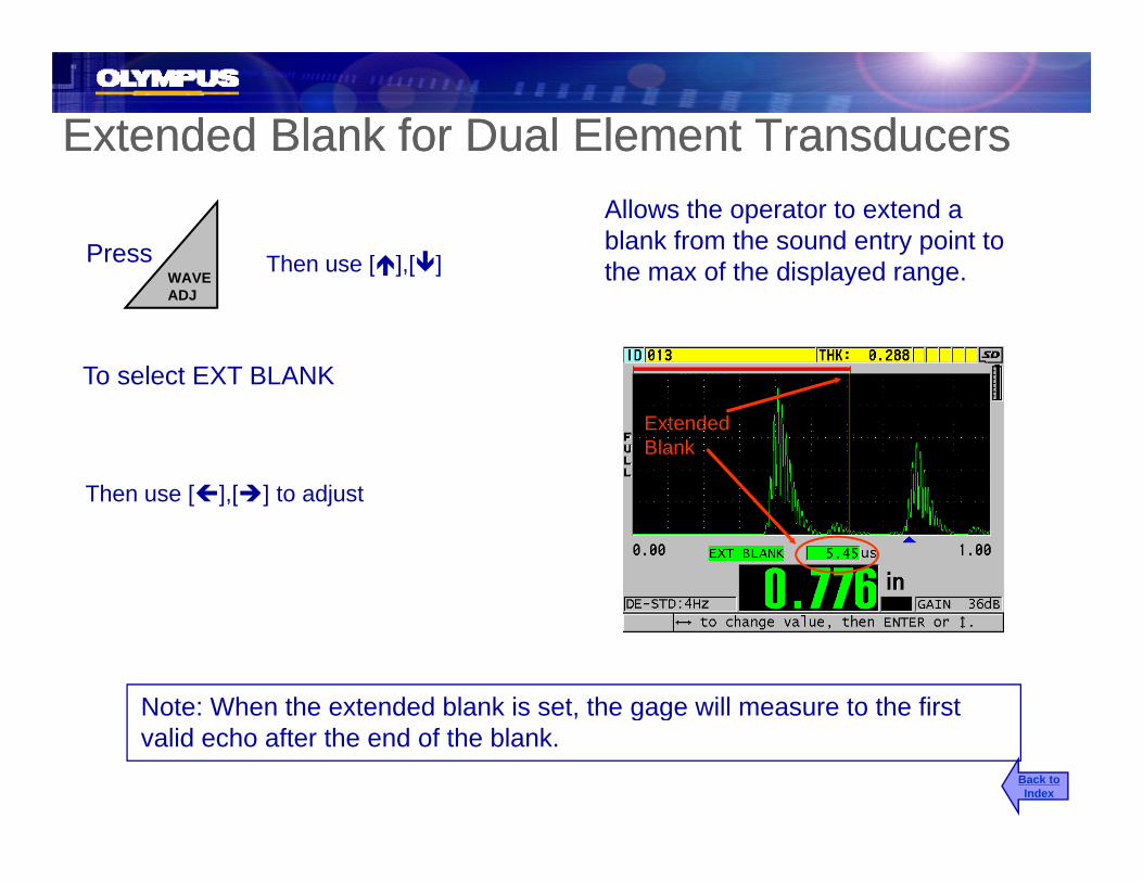
Extended Blank for Dual Element TransducersExtended Blank for Dual Element Transducers
Press
Allows the operator to extend a blank from the sound entry point to the max of the displayed rangeWAVE
Then use [ ],[ ] the max of the displayed range.
To select EXT BLANK
WAVEADJ
[ ],[ ]
ExtendedBlank
Then use [ ] [ ] to adjustThen use [ ],[ ] to adjust
Note: When the extended blank is set, the gage will measure to the first g gvalid echo after the end of the blank.
Back toIndex

Extended BlankExtended BlankExtended BlankExtended Blank
NOISEDETECTED
PROPERDETECTION
ExtendedBlank
Gage reading noise signal above detection point.
Extended Blank set correctly. Gage making proper back wall detection.
Back toIndex
Model 38DL PLUSEcho-to-Echo Mode
Back toIndex

Echo-to-Echo with Dual Element TransducersEcho-to-Echo with Dual Element TransducersEcho-to-Echo with Dual Element TransducersEcho-to-Echo with Dual Element TransducersPress then The Echo-to-Echo function allows the
38DLPlus to make thickness readings 2nd F
E-TO-E
ZOOM
between multiple backwall echoes. This function can be used to measure the true metal thickness on most painted and coated materials
Use the [ ],[ ] keys to select the measurement mode and press [ENTER]
coated materials.
Note: To ensure that the gage will makeNote: To ensure that the gage will make accurate readings in both Echo-to-Echo and Standard Mode it is necessary to perform a Cal Vel and Cal Zero in the mode you plan to work in and a Cal Zero in the alternate measure mode.
Back toIndex

Auto Echo-to-Echo, Dual Element TransducersAuto Echo-to-Echo, Dual Element TransducersAuto Echo to Echo, Dual Element TransducersAuto Echo to Echo, Dual Element Transducers
The 38DLPlus will automatically make thi k t b t th hi h tthickness measurements between the highest amplitude backwall signal and the second highest amplitude backwall signal. The normal 20% echo detection rules do not apply to A t ti E h t E h t dAutomatic Echo-to-Echo measurement mode.
Echo-to-Echomarker
Note: The standard detection marker is replaced with a bracket drawn between the two measured echoes.
AEtoE: Auto Echo-to-EchoMEtoE: Manual Echo-to-Echo
Back toIndex

Manual Echo-to-Echo, Dual Element TransducersManual Echo-to-Echo, Dual Element Transducers
The user controls signal detection by adjusting the receiver gain and two blankingadjusting the receiver gain and two blanking gates. The gage will automatically detect the highest amplitude echo and the next signal.
E1 BlankExtendedBlank
Press the [WAVE AD\J] key then use the [ ] y[ ],[ ] keys to select between Gain, Extended Blank and E1 Blank Use [ ],[ ]to adjust the parameter
Back toIndex

Echo-to-Echo Measurement TipsEcho-to-Echo Measurement TipsEcho to Echo Measurement TipsEcho to Echo Measurement Tips
Backwall 1 E1 Blank E1 Blank
Shear waveEcho
Backwall 2
Improper detection usingManual Echo-to-Echo
Proper detection using Blank adjustment
Note: Shear wave echoes can cause Echo-to-Echo measurement problems with the D790 in the thickness range of .600”-1.00”. We recommend using the D797 for the thicker Echo-to-Echo measurements or D7906 in Echo-to-Echo or in THRU-COAT mode. The delay material of the D7906 reduces shear wave
Back toIndex
echo propagation
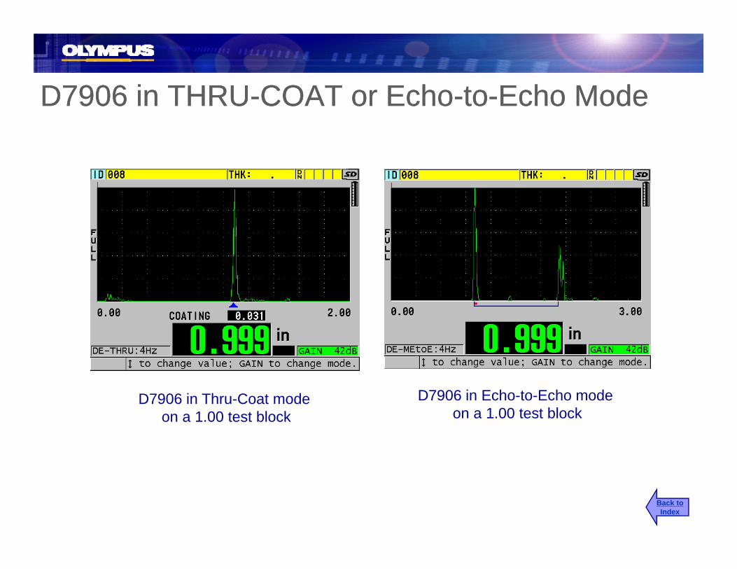
D7906 in THRU-COAT or Echo-to-Echo ModeD7906 in THRU-COAT or Echo-to-Echo ModeD7906 in THRU COAT or Echo to Echo ModeD7906 in THRU COAT or Echo to Echo Mode
D7906 i E h t E h dD7906 in Thru-Coat modeon a 1.00 test block
D7906 in Echo-to-Echo modeon a 1.00 test block
Back toIndex

Echo-to-Echo, No MultiplesEcho-to-Echo, No MultiplesEcho to Echo, No MultiplesEcho to Echo, No Multiples
No reading with Echo-to-Echo on a Thru-Coat on a heavily corroded sampleNo reading with Echo to Echo on aheavily corroded sample
Thru Coat on a heavily corroded sample
Back toIndex

M d l 38DL PLUSModel 38DL PLUSTemperature Compensation Feature

Temperature Compensation FeatureTemperature Compensation FeatureThe sound velocity in steel changes approximately 1% per 1000F (550C) change in temperature as recommended by ASME Standard E 797-95.
Compensated Thickness = Time of Flight *V0(1+k(T1-T0))Compensated Thickness Time of Flight V0(1 k(T1 T0))2
V0= Velocity at CalibrationT0= Temperature at Calibration T1= Temperature at Measurementk= Temperature coefficient
f (0 ) f (0C)k is typically -0.0001 for (0F) and -0.00018 for(0C)
Note: k can be determined for a given material by plotting velocity vs. temperature and using a straight line interpolation
Back toIndex
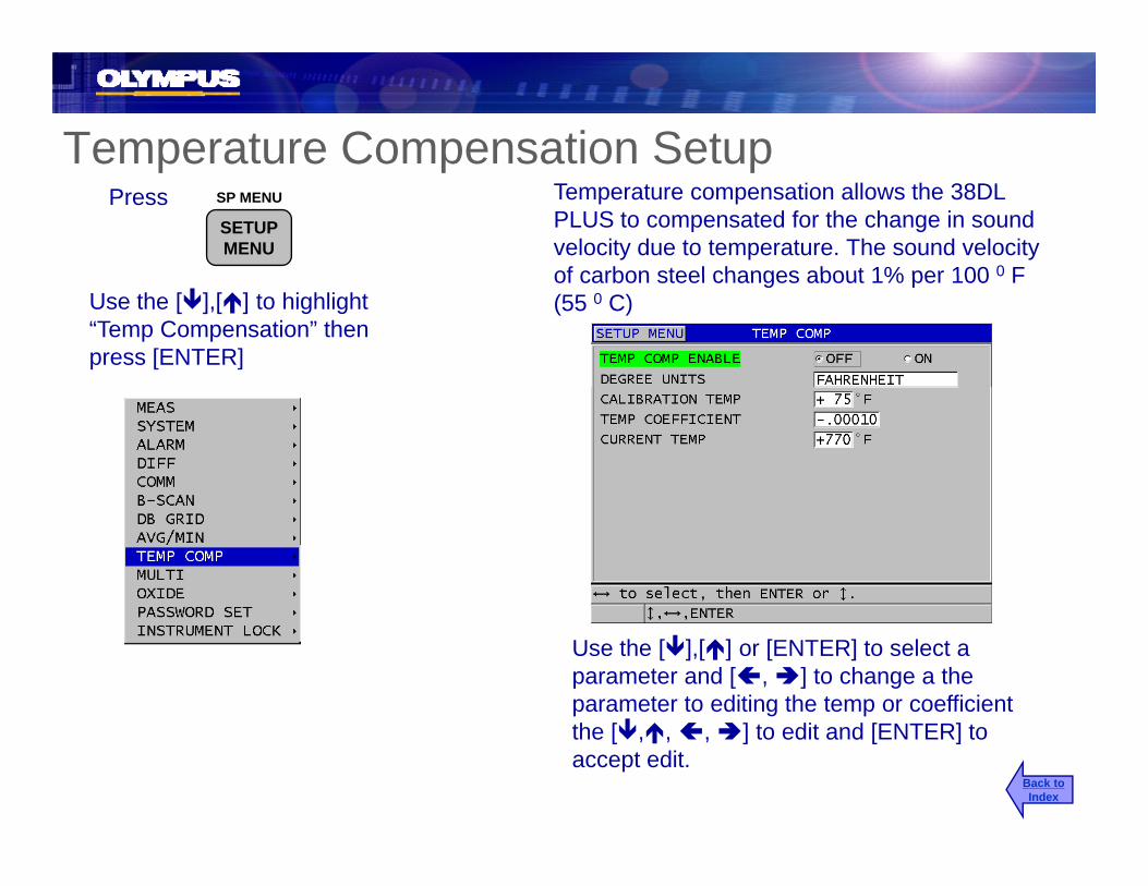
Temperature Compensation Setupe pe a u e Co pe sa o Se upPress Temperature compensation allows the 38DL
PLUS to compensated for the change in sound velocity due to temperature. The sound velocity of carbon steel changes about 1% per 100 0 F
SP MENU
SETUPMENU
of carbon steel changes about 1% per 100 0 F (55 0 C)Use the [ ],[ ] to highlight
“Temp Compensation” then press [ENTER]
Use the [ ],[ ] or [ENTER] to select a parameter and [ , ] to change a the parameter to editing the temp or coefficient
Back toIndex
the [ , , , ] to edit and [ENTER] to accept edit.
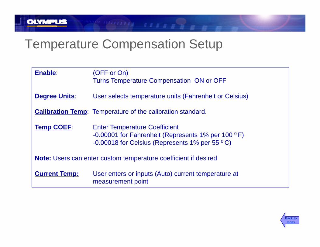
Temperature Compensation SetupTemperature Compensation Setup
Enable: (OFF or On)Turns Temperature Compensation ON or OFF
Degree Units: User selects temperature units (Fahrenheit or Celsius)
Calibration Temp: Temperature of the calibration standard.
Temp COEF: Enter Temperature Coefficient -0.00001 for Fahrenheit (Represents 1% per 100 0 F)-0.00018 for Celsius (Represents 1% per 55 0 C)
Note: Users can enter custom temperature coefficient if desired
Current Temp: User enters or inputs (Auto) current temperature at measurement point
Back toIndex

Temperature Compensation ModeTemperature Compensation ModeWhen Temperature Compensation is activated and in the measure mode
Press2nd F
REF VALUE
XDCRRECALLThen
Enter the temperature at the measurement pointEnter the temperature at the measurement point and press [MEAS]
Note: Current temperature will remain as set until h d bchanged by user.
Back toIndex

Temperature Compensation ModeTemperature Compensation Mode
Current TempEntered by userTemperature
compensatedpthickness
Back toIndex

Model 38DL PLUSMin/Average Setup
Back toIndex

Min/Average SetupMin/Average SetupAllows user to save the Minimum or Average of 2, 3 or 4 thickness readingsPress SP MENU
SETUPMENU
Use the [ ],[ ] to highlight “AVG/MIN” then press [ENTER]
MENU
Use the [ ] [ ] to highlight
Use the [ ],[ ] to select a parameter and [ ],[ ]to change
Use the [ ],[ ] to highlight “AVG/MIN” then press
the settingBack toIndex
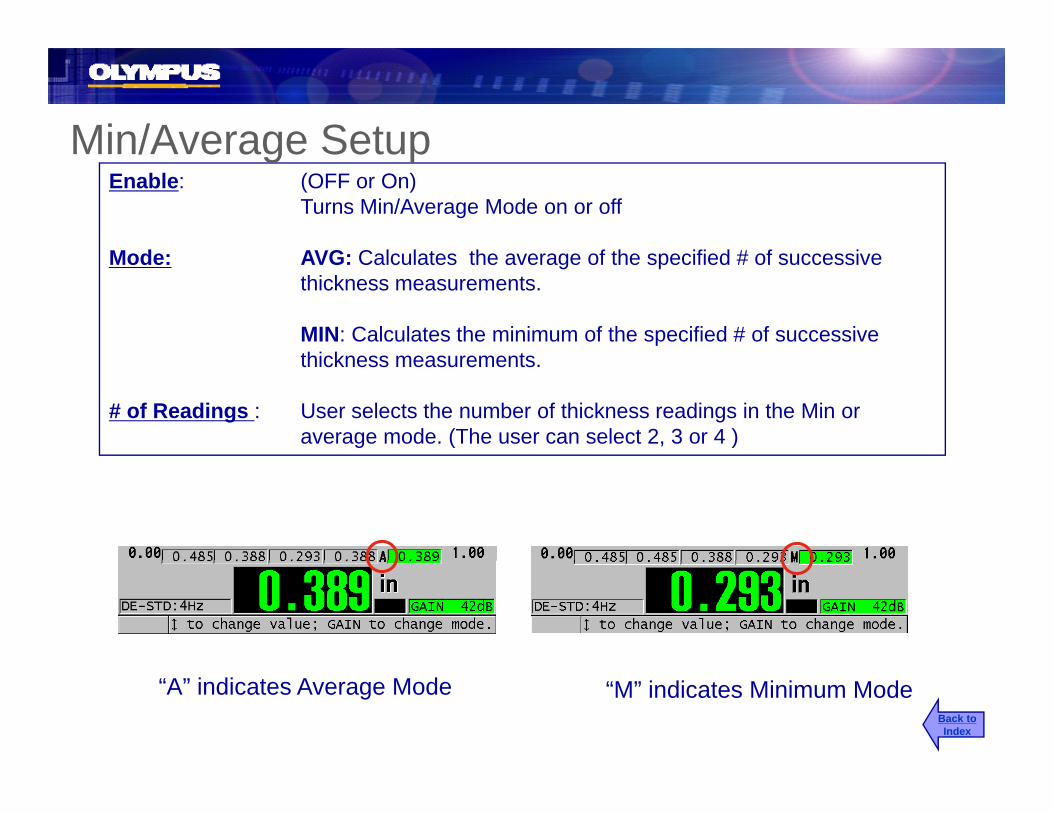
Min/Average SetupEnable: (OFF or On)
Turns Min/Average Mode on or off
M d AVG C l l t th f th ifi d # f i
Min/Average Setup
Mode: AVG: Calculates the average of the specified # of successive thickness measurements.
MIN: Calculates the minimum of the specified # of successive thi k tthickness measurements.
# of Readings : User selects the number of thickness readings in the Min or average mode. (The user can select 2, 3 or 4 )
“A” indicates Average Mode “M” indicates Minimum Mode Back toIndex

Min/Average Operationg pPress [SAVE] to capture the current reading and move to the next location
[SAVE][ ]
Pressing [SAVE] whenthe Min or Average box ishighlighted will save the Minor Average value to the datalogger
Note: Pressing the [MEAS] key will clear all Min/Avg boxes. Using the [ or ] keys allows the user to move to any of the Min/Avg boxes and the value can be replaced by pressing the
or Average value to the datalogger
save key.
Back toIndex
Model 38DL PLUSB-Scan Mode
Back toIndex
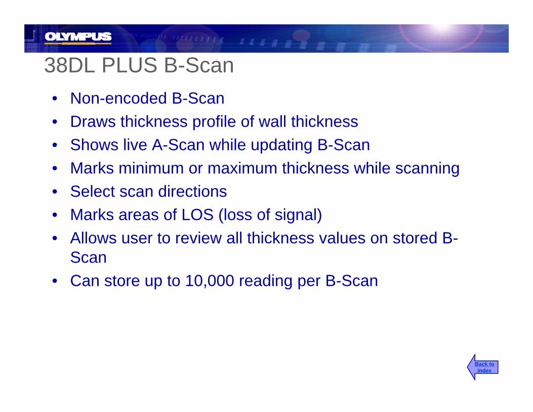
38DL PLUS B-Scan• Non-encoded B-Scan• Draws thickness profile of wall thicknessp• Shows live A-Scan while updating B-Scan• Marks minimum or maximum thickness while scanning• Select scan directions• Marks areas of LOS (loss of signal)
All t i ll thi k l t d B• Allows user to review all thickness values on stored B-Scan
• Can store up to 10 000 reading per B-ScanCan store up to 10,000 reading per B Scan
Back toIndex

Live B-Scan Display Overviewy
A-Scan
B-Scan
B-Scan Range
Transducer
CurrentMin/MaxMarker
Back toIndex
Live ThicknessMin or MaxThickness
Direction

B-Scan SetupB-Scan SetupB Scan SetupB Scan Setup
Used to activate B-Scan and set B-Scan parameters
PressSP MENU
SETUPMENU Scan parameters.
Use the [ ],[ ] to highlight “B-Scan” then press [ENTER]
Use the [ ],[ ] to select a parameter and [ ],[ ] to change the setting
Back toIndex
[ ],[ ] g g

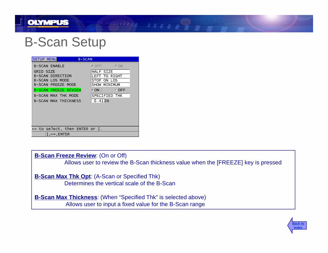
B-Scan SetupB-Scan SetupUse the [ ],[ ] to highlight the parameter and [ ],[ ] to change the parameter.Press [MEAS] to return to the [ ]measure mode with B-Scan active.
Option: (None, B-Scan or DB GRID)Setting Option to None turns B-Scan and DB Grid off
B-Scan Size: Full or Half, Half shows A-Scan and B-Scan
B-Scan Direction: (Right to Left or Left to Right)Determines the direction that the data will be updated or drawn on the screen.
B-Scan LOS Opt: (Stop or Continue)Determines how the B-Scan will operate when an LOS occurs.
B-Scan Freeze Opt: (Min, Max or Current) p ( )Determines which waveform and reading is displayed when the [FREEZE] key is pressed during a scan.
Back toIndex
B-Scan Setupp
B-Scan Freeze Review: (On or Off)Allows user to review the B-Scan thickness value when the [FREEZE] key is pressed
B S M Thk O t (A S S ifi d Thk)B-Scan Max Thk Opt: (A-Scan or Specified Thk)Determines the vertical scale of the B-Scan
B-Scan Max Thickness: (When “Specified Thk” is selected above)Allows user to input a fixed value for the B-Scan rangep g
Back toIndex

B-Scan “LOS” Opt set to “STOP”
LOS
B-Scan will stop updating when an LOS occurs. The B-Scan will start updating again when the next valid thickness reading is detected.
Note: If a valid thickness occurs after an LOS, a LOS marker indicating the position of the LOS will be inserted into the B-Scan.
Back toIndex

B Scan “LOS” Opt set to “CONTINUE”B-Scan LOS Opt set to CONTINUE
B-San will continue to update even if a LOS occurs
LOS Regions
Note: An LOS thickness is indicated as a blank thickness
Back toIndex

B-Scan Freeze ReviewB Scan Freeze Review
While collecting B-Scan data:FREEZEPress
Review
FREEZE
A vertical line (Review Marker) will appear to indicate the location of the
Marker
Midisplayed thickness.
This will be either the Minimum, Maximum, or current thickness
f
MinMarker
depending on the freeze option selected. The unit will display both the thickness and the waveform of the held minimum or maximum.
Back toIndex

B-Scan Freeze Review
Pressing
Review
[ ],[ ]
Moves the Review Marker to either the left or the right of the scan.
Marker
g
During review, the gage will always display the thickness at the Review Marker location.
Thickness at Review Marker
Back toIndex

Saving Thickness Readings in Freeze Modeg g
Press
While B-Scan is Frozen (Freeze Review On)
SAVE
WAVEFORMess
Review
SAVESEND
Marker
To save a thickness reading at the position of the Review Marker. The user can save the Min or Max thickness value by pressing thethickness value by pressing the [SAVE] key when the Min or Max is displayed.
Back toIndex

Saving B-Scan Screen or Entire B-ScanSaving the Min or Max A-Scan Along with the Held B-Scan
While B Scan is Frozen and the Min or
g
While B-Scan is Frozen, and the Min or Max is displayed:
SAVE
WAVEFORM
Press thenSEND
2nd F
Use [ ],[ ] to select NO to save only the current B-Scan screen or Yes to save the entire B-Scan up to 10,000 thickness and Press ,[ENTER]
Min Markerlocation
Back toIndex

Additional Gage FeaturesAdditional Gage FeaturesAdditional Gage FeaturesAdditional Gage Features
Diff i l• Differential
• Reduction Rate Alarms
M t U d t R t• Measurement Update Rate
• Min/Max Mode
• Alarm Mode• Alarm Mode
Back toIndex
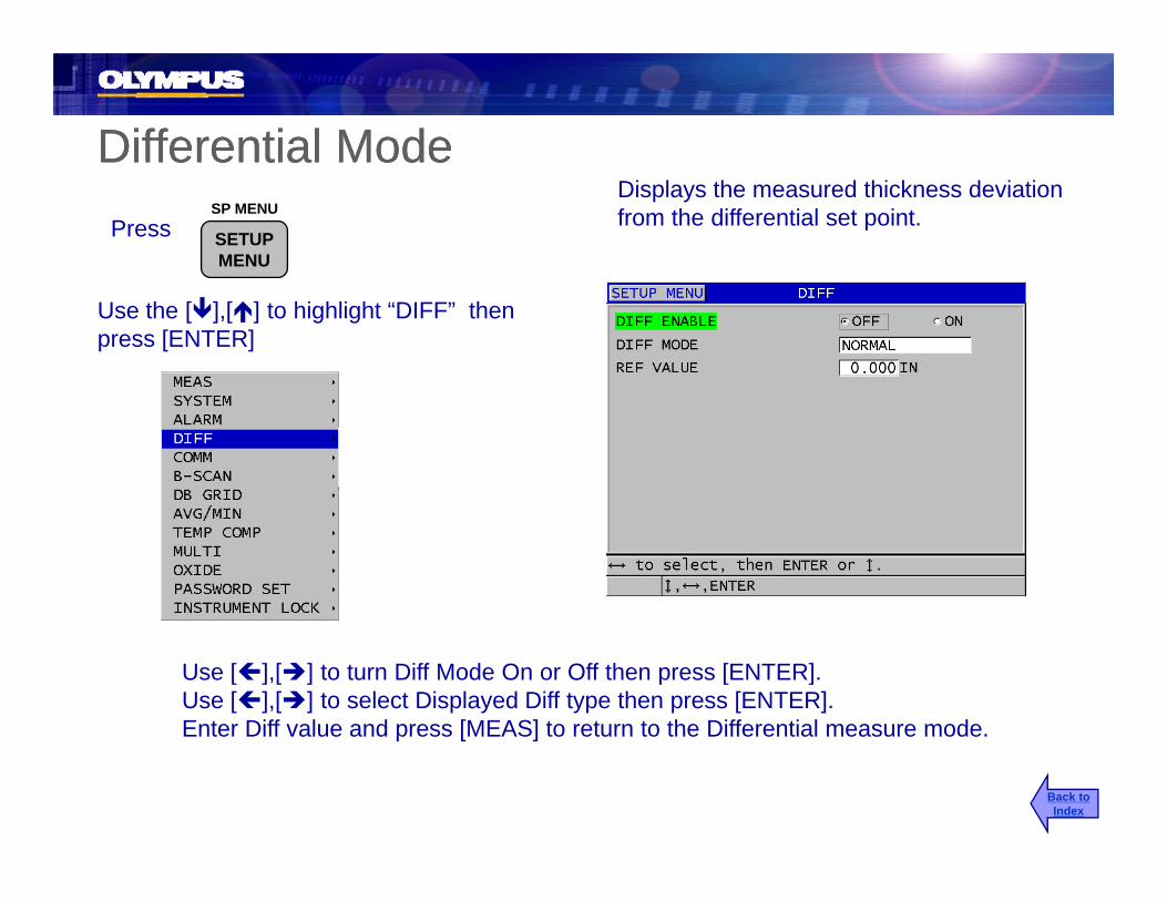
Differential ModeDifferential ModePress
Displays the measured thickness deviation from the differential set point.SP MENU
SETUPMENU
Use the [ ],[ ] to highlight “DIFF” then press [ENTER]
Use [ ],[ ] to turn Diff Mode On or Off then press [ENTER]. Use [ ],[ ] to select Displayed Diff type then press [ENTER].Enter Diff value and press [MEAS] to return to the Differential measure mode.Enter Diff value and press [MEAS] to return to the Differential measure mode.
Back toIndex
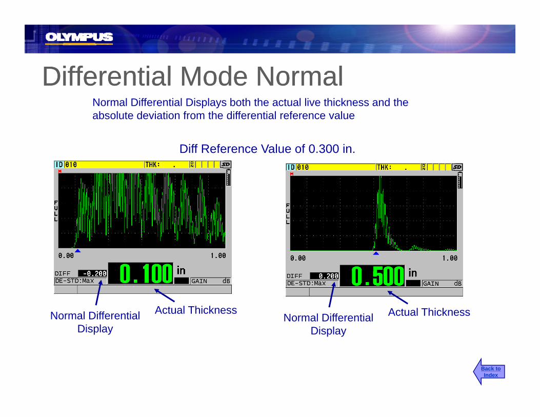
Differential Mode NormalDifferential Mode NormalDifferential Mode NormalDifferential Mode NormalNormal Differential Displays both the actual live thickness and the absolute deviation from the differential reference value
Diff Reference Value of 0.300 in.
Actual ThicknessNormal DifferentialDisplay
Actual ThicknessNormal DifferentialDisplay
Back toIndex

Differential Mode % RatioDifferential Mode % RatioDifferential Mode % RatioDifferential Mode % Ratio% Ratio Differential Displays both the actual live thickness and the % deviation from the differential reference value
Diff Reference Value of 0.300 in.
Actual Thickness% DifferentialDisplay
Actual Thickness% DifferentialDisplay
Back toIndex
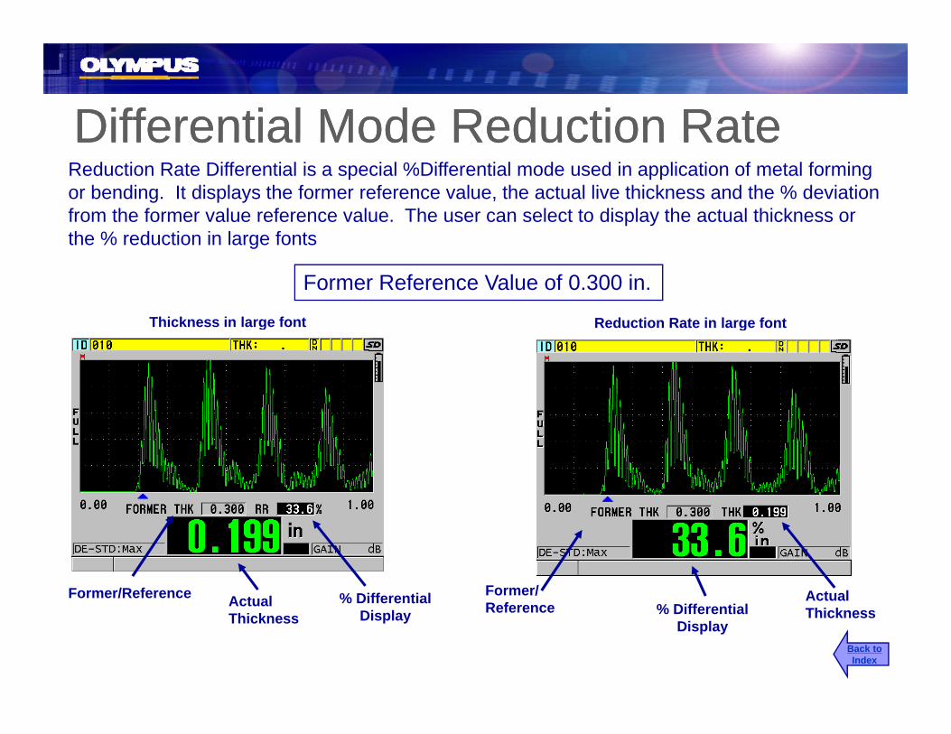
Differential Mode Reduction RateDifferential Mode Reduction RateDifferential Mode Reduction RateDifferential Mode Reduction RateReduction Rate Differential is a special %Differential mode used in application of metal forming or bending. It displays the former reference value, the actual live thickness and the % deviation from the former value reference value. The user can select to display the actual thickness or the % reduction in large fonts
Former Reference Value of 0.300 in.
Thickness in large font Reduction Rate in large fontThickness in large font Reduction Rate in large font
Actual % DifferentialFormer/Reference Former/ ActualActual Thickness
% DifferentialDisplay Reference
Actual Thickness% Differential
DisplayBack toIndex

Reduction Rate AlarmsReduction Rate AlarmsReduction Rate AlarmsReduction Rate AlarmsIf Reduction Rate is active the user can set the alarms values. These are set in the alarm setup menu. The user can define a
While Reduction rate is active Press SP MENU
Yellow and Red Alarm set pointsSETUPMENU
Use the [ ],[ ] to highlight “Alarm”then press [ENTER]then press [ENTER]
Use [ ],[ ] to turn Alarm Mode On or Off then press [ENTER].Use [ ],[ ] to turn Alarm Mode On or Off then press [ENTER]. Use [ , , , ] to edit the Yellow Alarm then press [ENTER].Use [ , , , ] to edit the Yellow Alarm then press [ENTER]. Back to
Index

Reduction Rate AlarmsReduction Rate AlarmsReduction Rate AlarmsReduction Rate Alarms
Reduction rates of 0-19.9% is a Green alarm condition
Reduction rates of 20-36.9% is a Yellow alarm condition
Reduction rates of 30-Greater is a Red alarm condition
Back toIndex

Measurement Update RateMeasurement Update RateppPress
SP MENU
SETUPMENU
Allows the user to select the display measurement update rate. The user can select between (4, 8, 16, 20Hz or Max
Use the [ ],[ ] to highlight “Meas” then press [ENTER]
(approx 30 Hz).
Measurement Update Rate
Use the [ ],[ ] to highlight “Measurement Rate”, press [ENTER] then use the [ ],[ ] to change
]
Back toIndex
Measurement rate and press [ENTER]

Min/Max ModeMin/Max ModeThese two functions will allow the gage to scanThese two functions will allow the gage to scan and hold the Minimum, Maximum or Both Min and Max thickness and waveform. Any time the Min/Max modes are engaged, the gage will automatically go into Max Measurement update
PressSP MENU
SETUPMENU
Use the [ ] [ ] to highlight “Meas” then automatically go into Max Measurement update rate.
Use the [ ],[ ] to highlight Meas then press [ENTER]
Use the [ ],[ ] to highlight “MIN/MAX Measure Rate” then use the [ ] [ ] to
Note: The [FREEZE] key can be used in conjunction with the Min/Max
Measure Rate then use the [ ],[ ] to change between (OFF, MIN, MAX or Both) then press [MEAS]
to eliminate the possibility of capturing false couplant readings. Pressing [MEAS] will reset the Min/Max.
Back toIndex

Min/Max ModeMin/Max ModeMin/Max ModeMin/Max Mode
H ld M i Active ThicknessHeld Minimum Held MaximumActive Thickness
Active ThicknessHeld Min/
Back toIndex
Active ThicknessHeld Min/Maximum

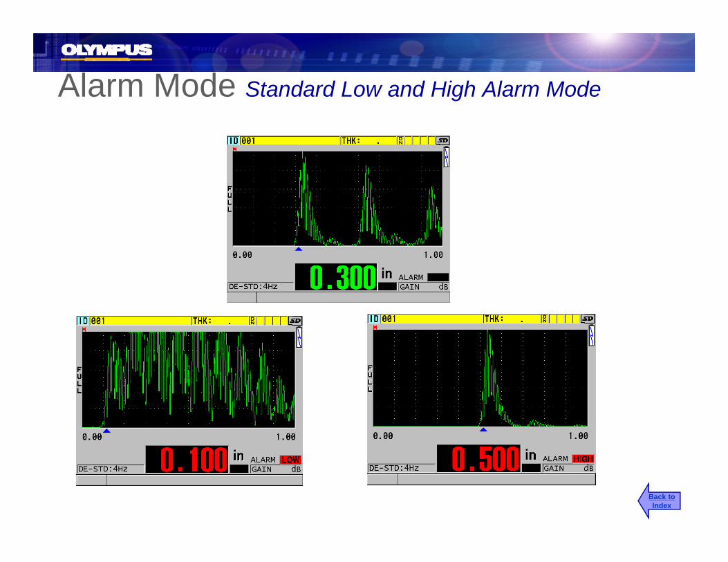
Alarm Mode Standard Low and High Alarm Mode
Allows the operator to set High and Low alarm set points. The gage will give both audible and visual alarm indicators.
PressSP MENU
SETUPMENU
Use the [ ] [ ] to highlight “Alarm” thenUse the [ ],[ ] to highlight Alarm then press [ENTER]
Use the [ ] [ ] to turn enable OFF or On and press [ENTER]Use the [ ],[ ] to turn enable OFF or On and press [ENTER]Use the [ ],[ ] to select alarm mode (Standard or Previous) and press [ENTER]Use [ , , , ] edit the Low alarm value and press [ENTER]Use [ , , , ] edit the High alarm value use press [MEAS]
Back toIndex
Alarm Mode Standard Low and High Alarm Mode
Back toIndex

Alarm Mode Absolute Previous Thickness Alarm Mode
Allows the user to compare current live thickness values to previously stored thickness values at each ID# location, for
PressSP MENU
SETUPMENU
Use the [ ] [ ] to highlight “Alarm” then the purpose of detecting large wall losses or growths.
Use the [ ],[ ] to highlight Alarm then press [ENTER]
Use the [ ] [ ] to turn enable OFF or On and press [ENTER]Use the [ ],[ ] to turn enable OFF or On and press [ENTER]Use the [ ],[ ] to select alarm mode (Standard or Previous) and press [ENTER]Use the [ ],[ ] to select Previous Thickness mode (Absolute or %) and press [ENTER]Use [ , , , ] to edit the absolute Loss alarm value and press [ENTER]Use [ ] to edit the absolute Growth alarm value then press [MEAS]
Back toIndex
Use [ , , , ] to edit the absolute Growth alarm value then press [MEAS]
Alarm Mode
Previous
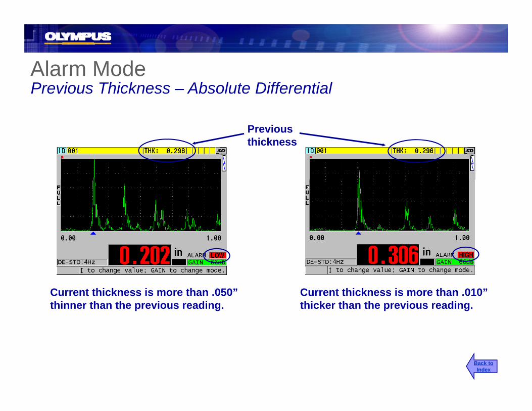
a odePrevious Thickness – Absolute Differential
Previous thickness
Current thickness is more than .050” thinner than the previous reading.
Current thickness is more than .010” thicker than the previous reading.
Back toIndex

Alarm ModeP i Thi k P t Diff ti lPrevious Thickness – Percent Differential
Allows the user to compare current live thickness values to previously stored thickness values at each ID# location for the purpose of
PressSP MENU
SETUPMENU values at each ID# location, for the purpose of
detecting large wall losses or growths. The user can set a % Loss or % Growth from the previously stored thickness.
MENU
Use the [ ],[ ] to highlight “Alarm” then press [ENTER]
Use the [ ],[ ] to turn enable OFF or On and press [ENTER]Use the [ ],[ ] to select alarm mode (Standard or Previous) and press [ENTER]Use the [ ],[ ] to select Previous Thickness mode (Absolute or % DIFF) and press [ENTER]
Back toIndex
Use [ , , , ] to edit the % Loss alarm value and press [ENTER]Use [ , , , ] to edit the % Growth alarm value then press [MEAS]

Alarm ModeP i Thi k P t Diff ti lPrevious Thickness – Percent Differential
PreviousPrevious thickness
Current thickness is more than 20% thinner than the previous reading.
Current thickness is more than 5% thicker than the previous reading.
Back toIndex

B-Scan Alarm ModeB-Scan must be active to set the B-Scan Alarm
SP MENU
Allows the user to set High and Low alarms for the B-Scan option. High and low alarm lines will be shown on the B-Scan
Press SETUPMENU
Use the [ ],[ ] to highlight “Alarm” then ]
the B Scan.
press [ENTER]
Use the [ ],[ ] to turn enable OFF or On and press [ENTER]Use the [ ] [ ] to select alarm mode (B-Scan) and press [ENTER]
Back toIndex
Use the [ ],[ ] to select alarm mode (B Scan) and press [ENTER]Use [ , , , ] to edit the Low alarm value and press [ENTER]Use [ , , , ] to edit the High alarm value then press [MEAS]
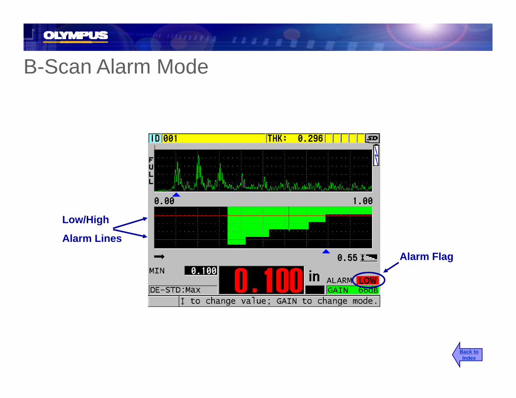
B-Scan Alarm ModeSca a ode
Low/High
Alarm Flag
g
Alarm Lines
Back toIndex

38DL PLUS Datalogger
Back toIndex

SelectableText Editing ModesSelectableText Editing ModesSP MENU
SETUPMENU
PressThe 38DL PLUS has two text editing modes: the new Virtual Keypad and the t diti l t t diti th t il blMENU
Use the [ ],[ ] to highlight “System”and press [ENTER]
traditional text editing that was available on our older generation thickness gages.
Use the [ ] [ ] to highlight Text Edit ModeUse the [ ],[ ] to highlight Text Edit Modeand [ , ] to select between Virtual and Traditional then press [MEAS]
Back toIndex

Virtual Keypad Text EditingVirtual Keypad Text EditingWhen Virtual Keypad text editing mode is selected the 38DL PLUS will display a p yvirtual keypad. This allows the user to interface with the entire of text in one field.
Use the [ , , , ] to high light a character and press [Enter] to add it to the text line. Highlight “DONE’ or press [2nd F], [ ] to end the text editing and move to the next linetext editing and move to the next line.
Note: When an outer character is highlighted pressing the arrow to move outside the Virtual keypad will cause the character on the opposite side of the Virtual keypad to highlight Thiskeypad will cause the character on the opposite side of the Virtual keypad to highlight. This keypad wrap around allows the user to quickly navigate through the character selection.
Back toIndex

Traditional Text EditingTraditional Text EditingWhen Traditional test editing mode is selected the user uses the [ , ] key to select the [ , ] ycharacter (letters, Numbers and punctuation) and [ , ] to move the curser. Pressing [ENTER] to complete the editing.
Note:[ ] key starts ABCD….#-…983210[ ] Key starts 0123…#-… ZYX [ ] moves the curser to the right [ ] moves the curser to the left[ENTER] complete the editing.
Back toIndex

Datalogger MemoryDatalogger MemoryPress Displays Datalogger Information:
• Current number of filesRemaining ID space
CLR MEM
FILE
• Remaining ID space• Remaining waveform space
Use the [ ],[ ] to highlight “Memory “then press [ENTER]
Back toIndex

File OpenFile Open Allows the user to open a previouslyppPress
Allows the user to open a previously created or downloaded file.
Then [ ] [ ] to select “Open” then
CLR MEM
FILE
Then [ ],[ ] to select Open then press [ENTER]
Use [ , ] to select sort by Name or Date then press [ENTER]
Note: The corresponding file header will be shown as you change your p [ ]
Use [ ],[ ] to select the File then press [ENTER]Use [ , ] to select Open or Cancel and [ENTER]
file selection.
Back toIndex
[ ]
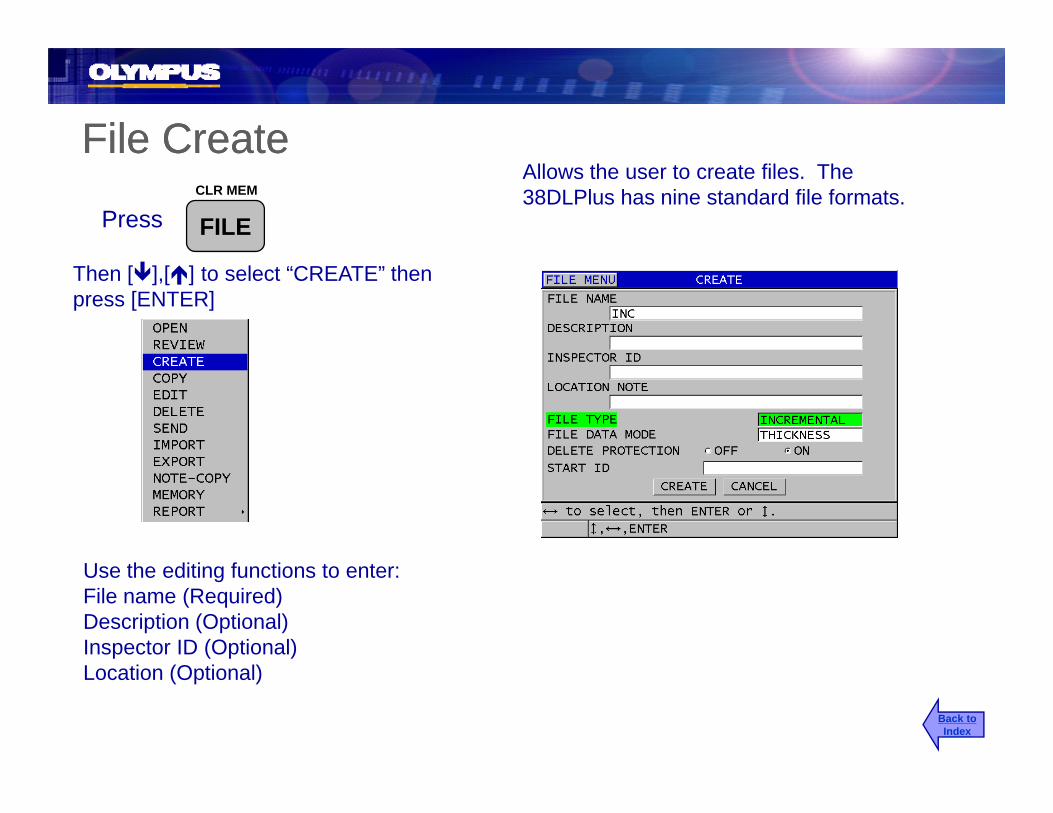
File CreateFile CreateFile CreateFile CreateAllows the user to create files. The 38DLPlus has nine standard file formats.
PressCLR MEM
FILE
Then [ ],[ ] to select “CREATE” then press [ENTER]
Use the editing functions to enter:File name (Required)Description (Optional)Inspector ID (Optional)Location (Optional)
Back toIndex

File Data ModeFile Data ModeThe 38DL PLUS has 10 File Data modes. The user needs to select the correct data mode for the type of data that will be stored in the file using the [ , ]
•Thickness: Store standard single element, Dual element and Echo-to-Echo measurements•THRU-COAT: Stores THRU-COAT measurements both the coating and metal thicknessTemp COMP: Stores Temperature compensated Thickness and Temperature setting•Temp COMP: Stores Temperature compensated Thickness and Temperature setting
•Oxide Layer: For optional Oxide software stores Tube and Internal oxide thickness•Velocity: Stores velocity values when using velocity mode•Time of Flight: Stores Time of Flight values when using Time of Flight mode•Reduction Rate: Stores Actual thickness and Reduction % when using Reduction Rate Modeg•Soft Contact For optional Multilayer software, stores Sagittal Height, Radius and Thickness of lens•%Total Thickness: For optional Multilayer software, stores thickness and % of total thickness readings•Min/Max: Stores both Min and Max thickness as a single ID#
Back toIndex

Incremental FileIncremental FileIncremental FileIncremental FileIncremental files will start at the entered point and increment from the right when the save key is pressed.
E lExample:001002003...
999Enter the starting ID# using the editing controls then g g gpress [ENTER]. Use [ ],[ ] to choose [Create] then press [ENTER]
Back toIndex
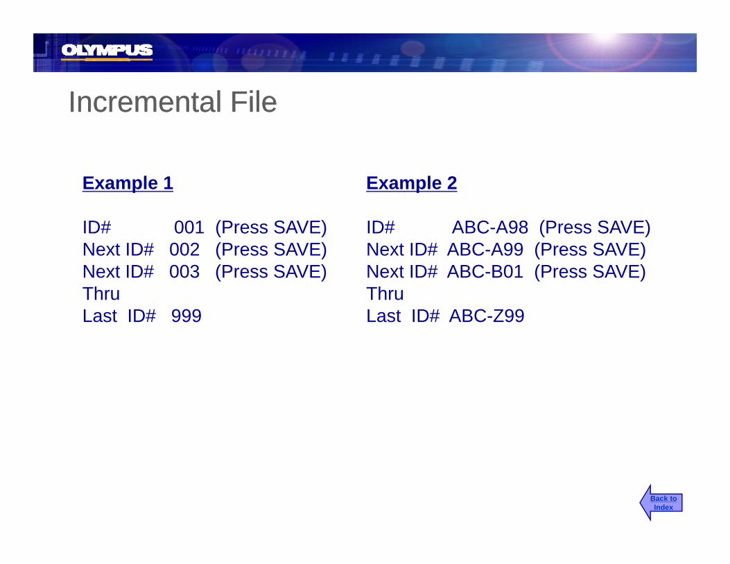
Incremental FileIncremental FileIncremental FileIncremental File
Example 1
ID# 001 (Press SAVE)Next ID# 002 (Press SAVE)
Example 2
ID# ABC-A98 (Press SAVE)Next ID# ABC A99 (Press SAVE)Next ID# 002 (Press SAVE)
Next ID# 003 (Press SAVE)ThruLast ID# 999
Next ID# ABC-A99 (Press SAVE)Next ID# ABC-B01 (Press SAVE)ThruLast ID# ABC-Z99Last ID# 999 Last ID# ABC-Z99
Back toIndex

Sequential FileSequential FileqqA sequential file starts at ID# 1 and increment until ID# 2. ID’s will increment in alphanumeric order from h i hSelect Sequential File type thickness mode and the right.Select Sequential File type, thickness mode and
file protections and press [ENTER]. Use [ ],[ ]to choose [CONTINUE] then press [ENTER].
Example:ELBOW-12-AELBOW-12-BELBOW-12-CELBOW-12-D
.
.
.ELBOW-12-H
Enter all parameters using the editing controls then press [ENTER]. Use [ ],[ ] to choose [Create] then p [ ] [ ],[ ] [ ]press [ENTER]
Back toIndex

Sequential File with Custom PointsSequential File with Custom PointsA sequential with custom point file starts at ID#1 and increments to ID#2 with a repeated custom point list attached to
Select Sequential + Custom PT File type, thickness mode and file protections and press each ID# point.thickness mode and file protections and press [ENTER]. Use [ ],[ ] to choose [CONTINUE] then press [ENTER].
Example: 001- LEFT 001- RIGHT 002- LEFT002 LEFT002- RIGHT 003- LEFT
.
..
.100- RIGHT
Enter each parameter use the editing controls then press [ENTER]. Use [2nd F], [ ] or press [ENTER] on a blank custom point to exit custom point. Choose [Create] then Press [ENTER][Create] then Press [ENTER].
Back toIndex

2D Grid File (Standard )2D Grid File (Standard )( )( )Allows the user to build two-dimension grid files by defining the starting column and row as well as ending column and row. The user
l h h di i h h fil illSelect 2D GRID File type, thickness mode and file
can also chose the direction that the file will increment.
protections and press [ENTER]. Use [ ],[ ] to choose [CONTINUE] then press [ENTER].
Example:A01B01C01D01A02B02
.
.M10
Enter all parameters using the editing controls then press and select Standard for ID format and press [ENTER]. Use [ ],[ ] to choose [Create] then press [ENTER]
Back toIndex
[ENTER].

2D Grid File (EPRI Format)( )Allows the user to build two-dimension grid files by defining the starting column and row as well as ending column and row. The user
l h th di ti th t th filcan also choose the direction that the file will increment. EPRI files use double letter columns, for columns past Z.
Select 2D GRID File type, thickness mode and file protections and press [ENTER]. Use [ ],[ ] to choose [CONTINUE] then press [ENTER].
Example:A01A01B01C01
.Z10Z10
AA01AA02
.FF10
Enter all parameters using the editing controls then press and select EPRI for ID format and press [ENTER] Use [ ] [ ] to choose [CONTINUE] then FF10[ENTER]. Use [ ],[ ] to choose [CONTINUE] then press [ENTER] and enter header information then choose {Done or Cancel}. Back to
Index

2D Grid File (Standard)2D Grid File (Standard)EXAMPLE:
Fi t ID# TANK A01Increment by: Increment by:
2D Grid File (Standard)2D Grid File (Standard)
First ID# TANK-A01
Last ID# TANK-E05
Row
TANK-A01TANK-A02
Column
TANK-A01TANK-B01TANK A02
TANK-A03TANK-A04TANK-A05TANK B01
A B C D E01 X
TANK B01TANK-C01TANK-D01TANK-E01TANK A02TANK-B01
TANK-B02...TANK E05
02
03
TANK-A02TANK-B02...TANK E05TANK-E0504
05
TANK-E05
Back toIndex

2D Grid File with Custom Points2D Grid File with Custom PointsAllows to user to build three-dimension grid files by defining starting/ending column and row. A custom list of included points may also be entered The user can also choose
2D Grid File with Custom Points2D Grid File with Custom Points
Select 2D +Custom PT File type thickness mode also be entered. The user can also choose the order in which the parameters increment.
Select 2D +Custom PT File type, thickness mode and file protections and press [ENTER]. Use [ ],[ ] to choose [CONTINUE] then press [ENTER].
Example:A01- TOPA01 TOPA01- BOTTOMA02- TOPA02- BOTTOM
.
.
.G05- BOTTOMEnter each parameter using the editing controls then
press [Enter] Use [2nd F] [ ] or press [ENTER] on apress [Enter]. Use [2nd F], [ ] or press [ENTER] on a blank line to exit custom point. Choose [Create] and then press [ENTER]. Back to
Index

3D Grid File3D Grid FileAllows the user to build three-dimension grid files by defining the starting and ending Column, Row, and Point. The user can also choose the order in which the parameters
3 G d e3 G d e
S l 3D G id Fil hi k d d fil choose the order in which the parameters increment.
Select 3D Grid File type, thickness mode and file protections and press [ENTER]. Use [ ],[ ] to choose [CONTINUE] then press [ENTER].
Example:A01AA01BA01CA01CA01DA02A
.
.
.Z15DEnter all parameters using the editing controls then
press [ENTER]. Use [ ],[ ] to choose [Create] p [ ] [ ],[ ] [ ]then press [ENTER].
Back toIndex
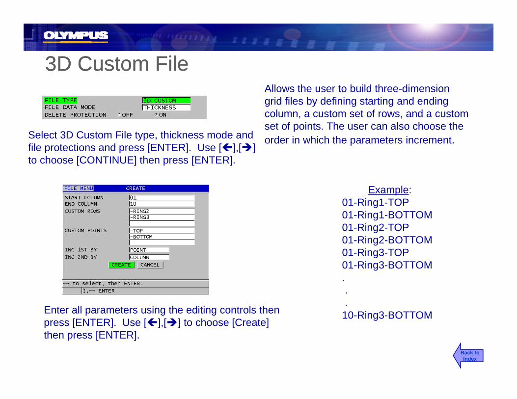
3D Custom File3D Custom FileAllows the user to build three-dimension grid files by defining starting and ending column, a custom set of rows, and a custom set of points The ser can also choose theset of points. The user can also choose the order in which the parameters increment.Select 3D Custom File type, thickness mode and
file protections and press [ENTER]. Use [ ],[ ]to choose [CONTINUE] then press [ENTER].
Example:01-Ring1-TOP01-Ring1-BOTTOM01 Ri 2 TOP01-Ring2-TOP01-Ring2-BOTTOM01-Ring3-TOP01-Ring3-BOTTOM ...10-Ring3-BOTTOMEnter all parameters using the editing controls then
press [ENTER]. Use [ ],[ ] to choose [Create]press [ENTER]. Use [ ],[ ] to choose [Create] then press [ENTER].
Back toIndex

Boiler FileBoiler FileBoiler FileBoiler FileAllows to user to build three-dimension boiler files by defining the starting and ending tube as well as custom points and Select Boiler File type, thickness mode and file
protections and press [ENTER] Use [ ] [ ] to elevations. The user can also choose the order in which the parameters increment.
protections and press [ENTER]. Use [ ],[ ] to choose [CONTINUE] then press [ENTER].
Enter each parameter using the editing controls then press [ENTER]. When in Custom Point or Elevation use [2nd F], [ ] or press [ENTER] on a blank line to exit the parameter Choose [Create] and the [ENTER]exit the parameter. Choose [Create] and the [ENTER]
Back toIndex

Boiler FileBoiler FileEXAMPLE:
Fist ID# 0FT-01A Increment by:
Last ID# 40FT-03C
Increment by: Point, Tube, Elevation
0ft-01-L0ft 01 C
01 02 030ft-01-C 0ft-01-R 0ft-02-L0ft-02-C
L
C
R
R
L
C
R
R
L
C
R
R30 ft
40 ft
0ft-02-R...40ft-03C
LC
RL
R LC
RL
R LC
RL
R
20 ft
30 ft
R
CL
L R
CL
L R
CL
L R0 ft
20 ft
C C C0 ftx
Back toIndex

ID# Entry/EditID# Entry/EditID# Entry/EditID# Entry/EditPress
ID# ‘s can be 16 characters with letters, numbers, alphanumeric and ( , / * . # NOTE
Twicep (
- space)
The gage will enter the ID Edit mode Use
ID#
The gage will enter the ID Edit mode Use the editing function to edit the ID# using arrow keys. Press the [ENTER] key while done is highlighted to jump to the edited ID# and return to ID# review or theID# and return to ID# review or the [MEAS] key to return to the measurement mode at the edited ID# location
Back toIndex

Saving Thickness Readings/WaveformsSaving Thickness Readings/WaveformsSaving Thickness Readings/WaveformsSaving Thickness Readings/Waveforms
Press Saves the thickness reading or thickness WAVEFORM greadings and waveforms at the current ID# location.
SAVESEND
While getting a steady reading or while a held frozen reading is displayed.
th
Note: The [SAVE/SEND] key can be programmed as a SAVE or SEND function. The SAVE/SEND key can be set to automatically save both thickness readings
Press
2 d FSAVESEND
WAVEFORM
then
To save both Thickness Readings and Waveforms
y gand waveforms when the SAVE/SEND key is pressed. Configure the SAVE/SEND key in System Set Up Menu.
2nd F
g
Back toIndex

Insert/Append ID# into a FileInsert/Append ID# into a FileInsert/Append ID# into a FileInsert/Append ID# into a FilePress The user can insert a new ID# and reading
into an existing file or append a new ID# and reading which will be add at the end of
Note:
Twiceand reading which will be add at the end of the entire file.
Use the standard editing controls to enter the new ID location. Then
ID#
press the [ID#] key or [MEAS] key.
Appended ID#’s will be add to the end of the ti filentire file.
Inserted ID#’s will be inserted before the last active ID# prior to leaving the measure mode.
Use [ ],[ ] to select and press [ENTER] Back toIndex

ID ReviewID ReviewID ReviewID ReviewPress Allows the user to slew through the
entire file and review stored data.Note:
Using the up and down keys will th h ID# i th fil
Then use [ ],[ ]ID#
move through ID# in the open file.
Note: The user can jump [2ndF] [ ] to jump to the first ID# in a file or or [2ndF] [ ] to jump to the last ID# in a fileor or [2ndF],[ ] to jump to the last ID# in a file.
Note: The user can jump to a specific ID# location in the file by using the ID# edit function.
Back toIndex
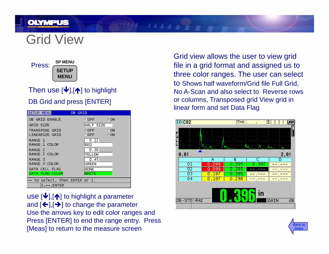
Grid ViewGrid view allows the user to view grid file in a grid format and assigned us to three color ranges. The user can select
Press: SP MENU
SETUPMENU
to Shows half waveform/Grid file Full Grid, No A-Scan and also select to Reverse rows or columns, Transposed grid View grid in linear form and set Data Flag
Then use [ ],[ ] to highlight
DB Grid and press [ENTER]g
use [ ],[ ] to highlight a parameter and [ ],[ ] to change the parameter
Back toIndex
[ ],[ ] g pUse the arrows key to edit color ranges and Press [ENTER] to end the range entry. Press[Meas] to return to the measure screen

Grid View Inserted PointsIf an ID# has been inserted into a Grid file then can not be displayed in normal grid View. If there are inserted reading in at a grid location the cell will be displayed with a gray background indicating p y g y g gthat there are inserted points at the grid location. Pressing [Zoom] on a grid point with inserted readings will cause the grid to expand into a linear format showing the inserted points. Pressing zoom again will return back to the standard Grid- --- zoom again will return back to the standard Grid view.
0.395-.----.---
.-.---
-.----.---
Inserted points
Inserted points
Back toIndex
Expanded view
p

Creating Notes (Comments)Creating Notes (Comments)g ( )g ( )The user can define up to 26 comments that are assigned letters A-Z. Each comment can be up to 16 characters
thenPress
2nd F ID#NOTE
plong. Comment lists can be built from the keypad or downloaded from the interface program.
Use [ ],[ ] to to select comment letter, then press [ ],[ ] to edit or add comment. Follow standard editing rules to enter comments.
Back toIndex

Adding Comments to the Current ID# LocationAdding Comments to the Current ID# LocationggUp to four comments can be saved with each ID#. A thickness reading can be saved along with the comments or the comments can be
thenPress 2nd F ID#NOTE
comments or the comments can be saved without a thickness reading.
Use [ ],[ ] to highlight the comment letter you want to use, then press [ENTER] to select/un-select the comment. Press [MEAS] after comments are selected and choose and the next time the [SAVE] key is pressed the comments will be saved withchoose and the next time the [SAVE] key is pressed the comments will be saved with the current ID#.
Back toIndex

Adding Comments to a Range of ID# LocationsAdding Comments to a Range of ID# Locationsg gg gUp to four comments can be saved with each ID#. A thickness reading can be saved along with the comments or the comments can be
thenPress 2nd F ID#NOTE
comments or the comments can be saved without a thickness reading.
Use [ ],[ ] to highlight the comment letter you want to use, then press [ENTER] to select/un-select the comment. Press [2ndF], [ ] after comments are selected and edit the start ID# location and then edit the ending DD# location. Use the [ ],[ ] to highlight [SAVE] and press [ENTER]. The comments selected will be save to the range of ID#’s.
Back toIndex
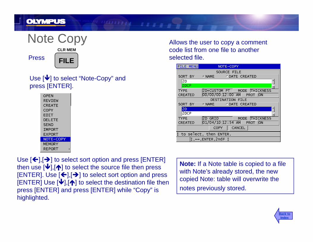
Note Copy Allows the user to copy a comment py pycode list from one file to another selected file.Press
CLR MEM
FILE
Use [ ] to select “Note-Copy” and press [ENTER].
Use [ ],[ ] to select sort option and press [ENTER] then use [ ] [ ] to select the source file then press Note: If a Note table is copied to a file then use [ ],[ ] to select the source file then press [ENTER]. Use [ ],[ ] to select sort option and press [ENTER] Use [ ],[ ] to select the destination file then press [ENTER] and press [ENTER] while “Copy” is highlighted
pwith Note’s already stored, the new copied Note: table will overwrite the notes previously stored.
highlighted.
Back toIndex

38DL PLUS Sending, Printing and g, gDeleting Data
Back toIndex

Sending a File or Multiple Files (RS-232 only)Sending a File or Multiple Files (RS-232 only)Sending a File or Multiple Files (RS 232 only)Sending a File or Multiple Files (RS 232 only)Allows the user to send a single file, multiple files or all files to a
t i t i RS 232Press CLR MEM
FILE
U [ ] [ ] t l t “S d” th [ENTER]
computer or printer via RS-232. This is function is not used with GageView.
FILE
Use [ ],[ ] to select “Send” then press [ENTER]Use [ ],[ ] to select selected or All and press [ENTER] Use [ ],[ ] to select sort option and press [ENTER]Use [ ],[ ] to select the file then press [ENTER] to mark it P [2 dF] [ ] fil l t dPress [2ndF] [ ], once files are selectedUse the [ ],[ ] to highlight “SEND” and press [ENTER] to send the marked files.
Back toIndex

Sending/Printing a Range of a File (RS-232 Only)Sending/Printing a Range of a File (RS-232 Only)Sending/Printing a Range of a File (RS 232 Only)Sending/Printing a Range of a File (RS 232 Only)Note: Connector type must be set to RS-232 Press and Send/Save must be set to
“SEND”
Allows the user to send a range of data in a file or the entire file to a printer or computer.
Press and holdSAVESEND
WAVEFORM
Until the range send screenappears on the display
Use the editing function to edit the first ID# in range and press [ENTER].Use the editing function to edit the Last ID in range and press [ENTER]
N t Thi d f ti l b
and press [ENTER].use [ ],[ ] to select “Send” or “Cancel” then press [ENTER].
Note: This send function can only be used on the current/active file.
Back toIndex

Deleting FilesDeleting Files The user can delete a file or multiple files and h t d l t th thi k d t lDeleting FilesDeleting Files
Press:can choose to delete the thickness data only or the entire file. Deleting the thickness data only will leave the ID# file structure.
CLR MEM
FILE
Use [ ],[ ] to select “Delete” then press [ENTER]
Use [ ],[ ] to select sort by Name or Date and press [ENTER] Use [ ] [ ] to select the file then press [ENTER] to mark itUse [ ],[ ] to select the file then press [ENTER] to mark it Press [2ndF] [ ], once files are selectedUse the [ ],[ ] to highlight DATA or FILE and press [ENTER]Use the [ ],[ ] to highlight “DELETE” and press [ENTER] to delete the marked files.
Back toIndex
Note: Only files that are not delete protected can be deleted

Deleting a range of data in a fileDeleting a range of data in a fileAllows the user to Clear/Delete a range of data in a file or the entire open file. Both ID# and thickness will be deleted in Incremental then
Deleting a range of data in a fileDeleting a range of data in a filePress:
2nd FCLR MEM
FILE and Sequential files. Only the thickness values will be deleted in Grid and Boiler files.
then
The Clear ID Range screenwill appear on the display
2nd F FILE
Use the editing function to edit the first ID# in rangeUse the editing function to edit the first ID# in range and press [ENTER].
Use the editing function to edit the last ID# in range and press [ENTER].
Note: This delete function can only be
Use [ ],[ ] to select “CLEAR” or “Cancel” then press [ENTER].
Note: This delete function can only be used on the current/active file.
Back toIndex

Deleting Single Thickness ReadingsDeleting Single Thickness Readings
Use [ ] [ ] keys or editing function
Allows the user to delete a single ID# point and it’s associated thickness reading (and/or waveform) This will also remove the ID#
Deleting Single Thickness ReadingsDeleting Single Thickness ReadingsPress:
NOTEUse [ ],[ ] keys or editing functionto highlight the ID# to delete
waveform). This will also remove the ID# from the datalogger.ID#
then
Press:
2nd FCLR MEM
FILE
Will delete the ID# and the thickness reading (and/or waveform)
Note: If you want to replace a thickness reading (and/or waveform) simply edit to the ID# point in the file and press the [SAVE/SEND] key p y p p [ ] yand save over the old reading.
Back toIndex

File CopyFile CopyPress:
Use [ ] [ ] to select “Copy” then press
Allows the user to copy a file or the format of a file to another file. This is a quick way to create multiple files with the same structure.
CLR MEM
FILE
Use [ ],[ ] to select Copy then press [Enter]
Use [ ] [ ] to select sort option and press [ENTER] then useUse [ ],[ ] to select sort option and press [ENTER] then use [ ],[ ] to select the file to copy then press [ENTER]
Use the editing functions to enter a file name for the new file then press [ENTER]
Back toIndex
Use [ ],[ ] to select Copy Data Yes or No and press [ENTER] while “Copy” is highlighted.

File Edit Rename (non grid files)File Edit Rename (non grid files)( g )( g )Press: Allows the user to edit the file header and
turn delete protection On/Off .
CLR MEM
FILE
Use [ ],[ ] to select “Edit” then press [Enter]
Use [ ],[ ] to select sort option and press [ENTER] then use [ ],[ ] to l t th fil t dit th [ENTER]select the file to edit then press [ENTER]
Use the editing functions to edit the a File Name, Description, Inspector ID and Notes, press [ENTER]
Use [ ],[ ] to change the file delete protection to On or Off and press
Back toIndex
[ ],[ ] g p p[ENTER]
Use [ ],[ ] to highlight UPDATE and press [ENTER]

File Edit Rename (Grid and Boiler Files)File Edit Rename (Grid and Boiler Files)( )( )Press:
Allows the user to edit the file header, add Rows or columns to grid files and change the incrementing direction.
CLR MEM
FILEUse [ ] [ ] to select “Edit” then press [Enter]
FILE EDIT-RENAME
Use [ ],[ ] to select “Edit” then press [Enter]
Use [ ],[ ] to select sort option and press [ENTER] then use [ ],[ ] to select the file to Edit then press [ENTER]
Use the editing functions to edit the a File Name, Description, Inspector ID and Notes and press [ENTER]
Use [ ],[ ] to change the file delete protection to On or Off and press [ENTER]
Use [ ],[ ] to highlight Continue and press [ENTER]
Back toIndex
Use the editing functions to edit the End Column, End Row and Incrementing Directions and Press [ENTER]
User the [ ],[ ] to highlight Update and press [ENTER]

File ReportsFile Reports
Allows the user to generate four different reports on the display of the 38DLPLUS.
Press: CLR MEM
FILEon the display of the 38DLPLUS.
Use [ ],[ ] to select “Reports” then press Use the [ ],[ ] enter the Report selection boxUse [ ],[ ] select a report and press [ENTER]
Back toIndex

File ReportsFile Reports
This report will give a statistical summary of the selected file
Use [ ],[ ] to select the sort option and press [ENTERUse [ ] [ ] to select a file then press [ENTER]
File Summary
selected file.Use [ ],[ ] to select a file then press [ENTER]Use [ ],[ ] to select report and press [ENTER]. And the statistics will be displayed.
Back toIndex
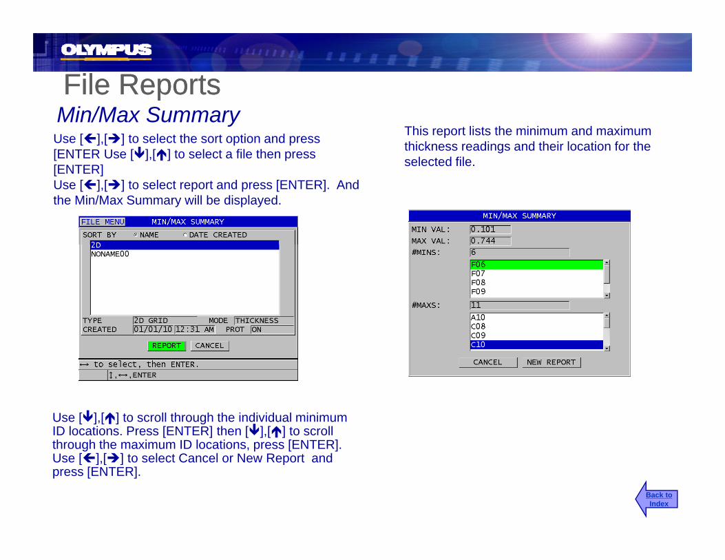
File ReportsFile ReportsThis report lists the minimum and maximum thickness readings and their location for the selected file.
Min/Max SummaryUse [ ],[ ] to select the sort option and press [ENTER Use [ ],[ ] to select a file then press [ENTER][ ]Use [ ],[ ] to select report and press [ENTER]. And the Min/Max Summary will be displayed.
Use [ ],[ ] to scroll through the individual minimum ID locations. Press [ENTER] then [ ],[ ] to scroll through the maximum ID locations, press [ENTER]. Use [ ] [ ] to select Cancel or New Report andUse [ ],[ ] to select Cancel or New Report and press [ENTER].
Back toIndex

File ReportsFile Reports
This report allow the gage to list the ID# of all the high and low alarm location for the selected file
ppAlarm Report
Use [ ],[ ] to select the sort option and press [ENTER] Use [ ],[ ] to select the file then high and low alarm location for the selected file.[ENTER] Use [ ],[ ] to select the file then press [ENTER]. Use [ ],[ ] to select report and press [ENTER].
Use [ ],[ ] to slew through the Low Alarm ID’s and then press [ENTER], use [ ],[ ] to scroll through the High Alarm ID’s and press [ENTER]. Use [ ],[ ] to select Cancel or New Report and
[ENTER]press [ENTER].
Back toIndex

File ReportsFile Reports
Use [ ],[ ] to select the sort option and press [ENTER Use [ ],[ ] to select the Reference
This report will compare the two selected files and show the maximum wall loss and locations, average wall loss and the locations of any wall
File Comparison
file then press [ENTER]. Use [ ],[ ] to select the Comparison file then press [ENTER]. Use [ ],[ ] to select report and press [ENTER].
average wall loss, and the locations of any wall growths.
Use [ ],[ ] to slew through ID’s with the maximum wall loss. Press [ENTER] then use [ ],[ ] to scroll through any ID’s that show wall growths then press [Enter]. Use [ ],[ ]wall growths then press [Enter]. Use [ ],[ ] to select Cancel or New Report and press [ENTER].
Back toIndex

File ReportsFile ReportsFile ReportsFile ReportsMin Review
Use [ ],[ ] to select the sort option and press This report lists all the ID# that have the minimum thickness value in the selected file. It also gives
[ENTER] Use [ ],[ ] to select the file then press [ENTER]. Use [ ],[ ] to select report and press [ENTER].
the user the choice to review/retake the readings at those locations by moving through the list of minimum locations.
Use [ ],[ ] to slew through ID’s with the Minimum wall thickness Press [ENTER]Minimum wall thickness. Press [ENTER] Use [ ],[ ] to select Review, Cancel or New Report and press [ENTER].
Back toIndex

File ReportsFile ReportsFile ReportsFile ReportsMin Review (REVIEW)
Use [ ],[ ] to jump to the next min ID# location the user can verify the reading to replace the current thickness reading or press [MEAS] to cancel the Min Review
Back toIndex

38DL PLUS Setup Menu
• Measurement
• System
• Communication
• DisplayBack toIndex
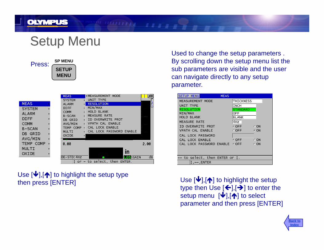
Setup MenuSetup MenuppUsed to change the setup parameters . By scrolling down the setup menu list the sub parameters are visible and the user can navigate directly to any setup
Press: SP MENU
SETUPMENU can navigate directly to any setup
parameter.
U [ ] [ ] t hi hli ht th t tUse [ ],[ ] to highlight the setup type then press [ENTER] Use [ ],[ ] to highlight the setup
type then Use [ ],[ ] to enter the setup menu [ ],[ ] to select parameter and then press [ENTER]
Back toIndex
parameter and then press [ENTER]

Measurement SetupMeasurement SetupUse [ ],[ ] to highlight the parameter and [ ],[ ] to change the parameter.p
Measurement Mode: Thickness, Velocity or Time of flight
Unit Type: Inches or MillimetersUnit Type: Inches or Millimeters
Resolution: Standard 0.001in. 0.01 mmLow 0.01 in. or 0.1 mmHigh 0.0001 in. or 0.001 mm (optional)
Min/Max: Off, Min, Max or Both
Hold/Blank: Hold: Holds last reading, Blank: Blanks last reading
Measurement Rate: 4Hz, 8Hz, 16Hz, 20Hz or Max (approximately 30 Hz)Measurement Rate: 4Hz, 8Hz, 16Hz, 20Hz or Max (approximately 30 Hz)
Back toIndex

Measurement Setup ContinuationMeasurement Setup ContinuationUse [ ],[ ] to highlight the parameter and [ ],[ ] to change the parameterchange the parameter.
ID Overwrite Protection: On or Off
V-Path Calibration: On or OffV-Path Calibration: On or Off
Cal Lock Password: User entered Cal Lock password
Cal Lock: On or Off
Cal Lock Password Enable: Supervisor Lock – On or Off
Back toIndex
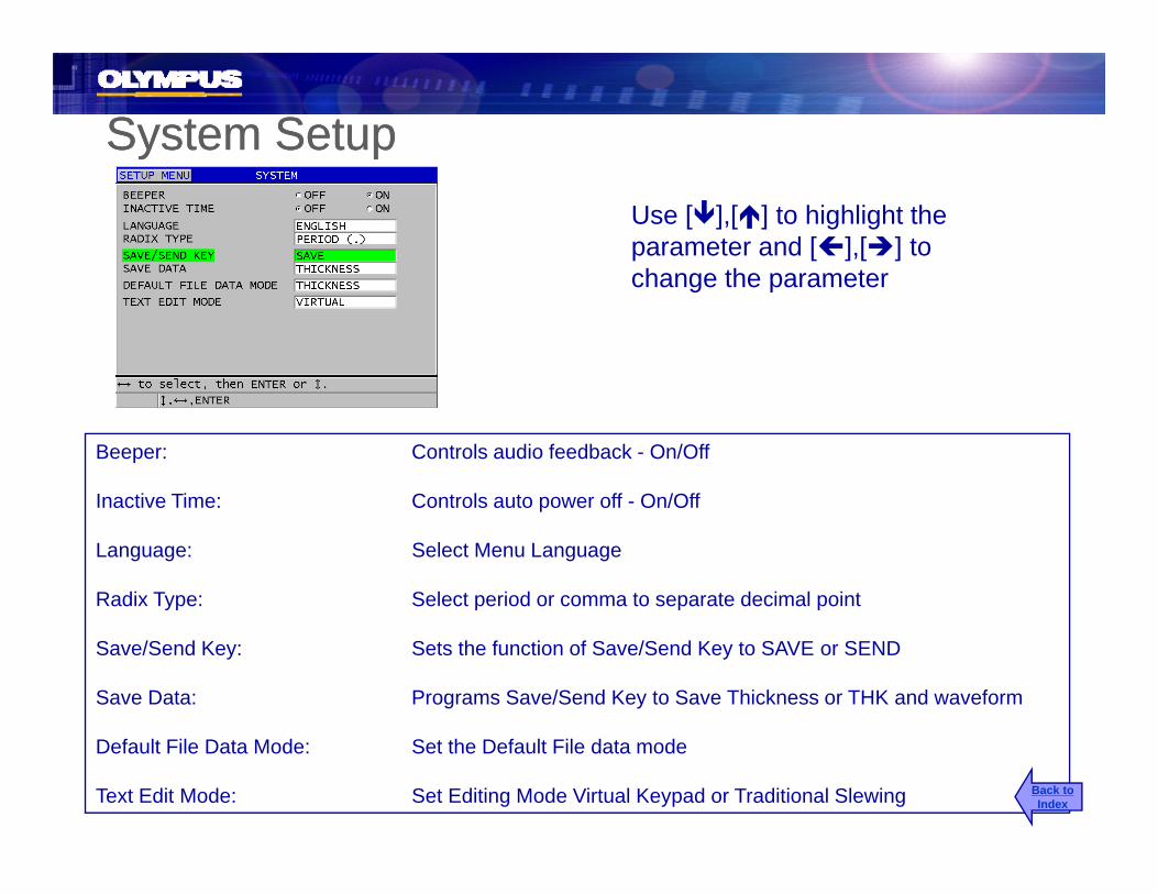
System SetupSystem SetupUse [ ],[ ] to highlight the parameter and [ ],[ ] to change the parameterchange the parameter
Beeper: Controls audio feedback - On/Off
Inactive Time: Controls auto power off - On/OffInactive Time: Controls auto power off On/Off
Language: Select Menu Language
Radix Type: Select period or comma to separate decimal point
Save/Send Key: Sets the function of Save/Send Key to SAVE or SEND
Save Data: Programs Save/Send Key to Save Thickness or THK and waveform
Default File Data Mode: Set the Default File data mode
Text Edit Mode: Set Editing Mode Virtual Keypad or Traditional Slewing Back toIndex

Communication SetupCommunication SetupppUse [ ],[ ] to highlight the parameter and [ ],[ ] to change the parameterchange the parameter
COMM Protocol: Set remote commands to Multi Character or Single
Output Format: Select F1-F10
DBase Tracking Tracks Setup from pervious inspection On or Off
B-Scan Output: Output or not output B-Scan data
37DL PLUS Output: Mimics the 36DL PLUS output
Connection Type: USB or RS-232
Back toIndex

Communication Setup (RS-232)Communication Setup (RS-232)p ( )p ( )Use [ ],[ ] to highlight the parameter and [ ],[ ] to change the parameter.p
RS-232 Device: Printer, Terminal (PC), Bar Code Reader, Digital Caliper, Fischer Gage, ( ), , g p , g
Baud Rate: 1200, 2400, 4800, 9600, 19200, 38400, 57600 or 115200
Continuous Output: Off, On, 5 Sec Average or 10 Sec Average
Note: The following RS-232 parameters are fixed at the values below:Data Bits: 8St Bit 1
Back toIndex
Stop Bits: 1Parity: None

Display SetupDisplay Setupp y pp y pUse [ ],[ ] to highlight the parameter and [ ],[ ] to change the parameterchange the parameter
Color Scheme: Sets display colors scheme to Indoor or Outdoor
Display Brightness: Set brightness of display backlight 0%, 25%, 50% or 100%
Waveform Rectification: Full, Half +, Half -, or RF
Waveform Trace: Outline or Filled in
VGA Output: Off or ONVGA Output: Off or ON
Back toIndex

38DL PLUS SP Menu38DL PLUS SP Menu
• Clock Setup• Clock Setup
• LanguageLanguage
• Gage Resetsg
• Diagnostic Testsg
• Status
Back toIndex

SP MenuSP MenuPress:
SP MENU
SETUP2nd F Then
The SP Menu is used to change the instrument parameters that are not often adjusted and to activate software options and to run diagnosticSETUP
MENU2nd F Then activate software options and to run diagnostic
instrument tests.
Use [ ],[ ] to highlight the SP Menu Item then press [ENTER]
Back toIndex
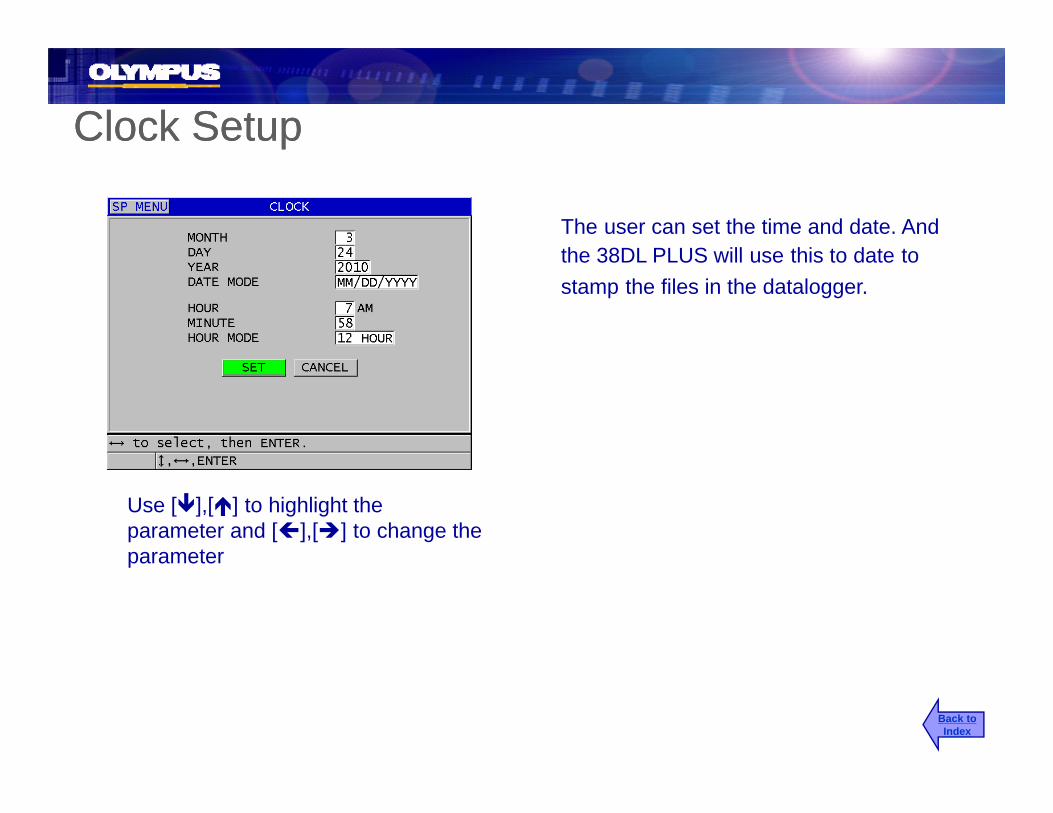
Clock SetupClock Setup
The user can set the time and date. And the 38DL PLUS will use this to date tothe 38DL PLUS will use this to date to stamp the files in the datalogger.
Use [ ],[ ] to highlight the parameter and [ ],[ ] to change the parameterparameter
Back toIndex

LanguageLanguage
The user can import custom language files from the external Micro SD memory
fcard or export a file to be translated and converted into a language file in the gage.
Use [ ],[ ] to highlight the parameter and [ ],[ ] to change the parameter
Back toIndex
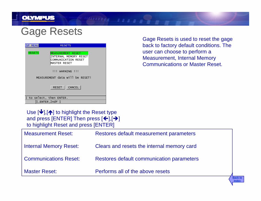
Gage ResetsGage ResetsG R t i d t t thGage Resets is used to reset the gage back to factory default conditions. The user can choose to perform a Measurement, Internal Memory C i ti M t R tCommunications or Master Reset.
Use [ ] [ ] to highlight the Reset typeUse [ ],[ ] to highlight the Reset type and press [ENTER] Then press [ ],[ ]to highlight Reset and press [ENTER]
Measurement Reset: Restores default measurement parameters
Internal Memory Reset: Clears and resets the internal memory card
Communications Reset: Restores default communication parameters
Master Reset: Performs all of the above resetsBack toIndex

Diagnostic TestsDiagnostic TestsDiagnostics is the gages self test mode. This allows the operator to run through software, keypad display, and hardware diagnostic testsdiagnostic tests.
Note: The following tests are not designed for use by the user and are part of our
Use [ ],[ ] to highlight the diagnostic test
y pmanufacturing tests:ESS testB-Scan TestBattery Test
and press [ENTER]
Keypad Test: Test to make sure each key is working
Video Test: Test each pixel on the display
yOne Wire test
Video Test: Test each pixel on the display
Internal SD card Test: Test the Internal SD memory card
External SD card Test: Test the Internal SD memory card
Dual XDCR Test: Reports RX and TX time of flight from Dual element transducerBack toIndex

Software Diagnostic TestSoftware Diagnostic TestSoftware diagnostic test reports and software error messages will be found under this tab .
Press [MEAS] to exit the SW Diagnostic testPress [MEAS] to exit the SW Diagnostic test.
Back toIndex

Status Status The status report lists the informationThe status report lists the information about the instrument including: internal temperature, current battery level, software version and hardware version of the 38DL PLUS.
Press [MEAS] to exit the Status Test
Back toIndex

38DL PLUS Single Element Internal Setup and T d Adj t tTransducer Adjustment
Back toIndex

Setup Adjust for Single Element Transducersp j g
Caution: Making adjustments to the Setup Parameters should be made by a qualified
Allows the user to adjust the pulser, receiver, detection and blanking parameters.
Pressindividual who is familiar with ultrasonics and the use of the 38DL PLUS. Adjustments made using this feature can affect the measurements.
WAVEADJ
Use [ ],[ ] to highlight the parameter and [ ],[ ] to change the parameter
AdjustmentParameter
Back toIndex

Mode 1
Mode 1 measures the time of flight between the Main Bang and the first back wall echo, using direct contact transducers.
Main Bang First
Back Wall
Back toIndex
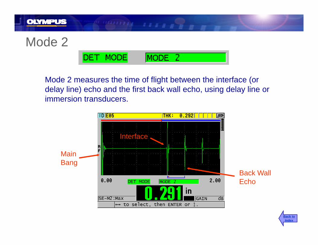
Mode 2Mode 2
Mode 2 measures the time of flight between the interface (or delay line) echo and the first back wall echo, using delay line or immersion transducers.
Interface
Main Bang
Interface
Back WallEcho
Back toIndex

Mode 3
Mode 3 measures the time of flight between one back wallMode 3 measures the time of flight between one back wall echo to the next back wall echo, using delay line or immersion transducers.
FirstBack Wall
Interface SecondB k W llBack Wall
Back toIndex

Setup Name
Default M-MetalP-Plastic
Mode1, 2 or 3
Frequency Transducer
• Default or user defined name that identifies the application setup that is currently selected
P Plastic 1, 2 or 3
currently selected
• Limited to 16 alphanumeric characters
Back toIndex

Measure Type
• For most single element transducer the Meas Type will be set to standard. Standard is for Standard Mode 1, Mode 2 and Mode 3 measurements.
• First Peak is a special algorithm to measure the first peak of a group of several peaks on either the positive or negative side of the waveform. Common uses would be for gel coat on fiberglass measurements or bolt elongation.elongation.
• Oxide Layer is a special measurement type used for displaying the thickness of boiler tubes and internal oxide at the same time. This feature is only available when the optional oxide software is activated
• Barrier is a special measurement algorithm used to measure the thickness of the barrier layer thickness in multi-layer plastic material. Typical applications are plastic fuel tanks, bottle preforms .
Back toIndex

Probe Typeyp
• Indicates the transducer type selected in the active setupP b t l t d h ld t h th f f th t d b i• Probe type selected should match the frequency of the transducer being used.
• Probe type sets the digital filters• Probe type sets the pulse width of the square wave pulser• Probe type sets the pulse width of the square wave pulser• Probe type sets the damping
Back toIndex
Pulser Power
• Indicates the voltage used to drive the transducer that is selected
• Affects the amount of energy going into the transducer and the size of• Affects the amount of energy going into the transducer and the size of the Initial pulse
• Select between 60, 110, 150 and 200 volts
Back toIndex
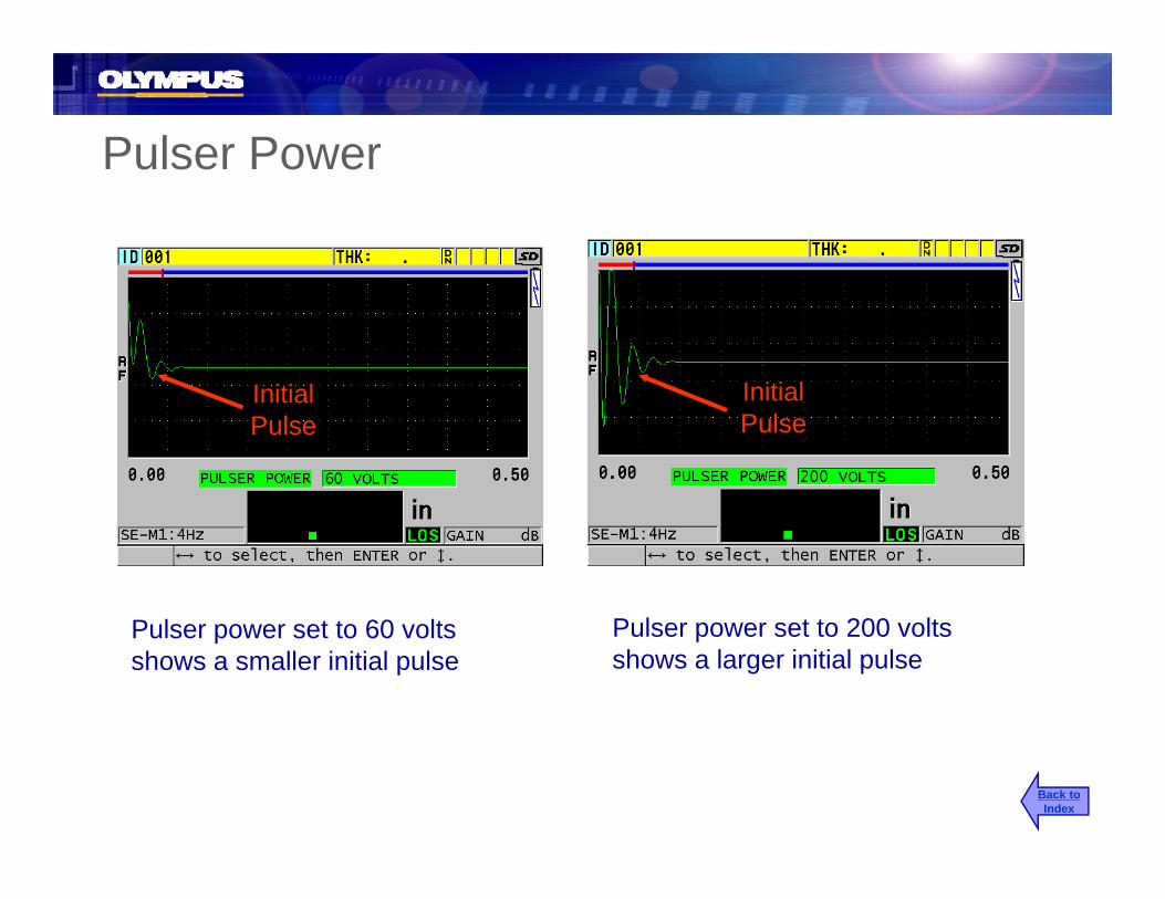
Pulser PowerPulser Power
Initial InitialInitialPulse
InitialPulse
P l t t 60 lt P l t t 200 ltPulser power set to 60 volts shows a smaller initial pulse
Pulser power set to 200 volts shows a larger initial pulse
Back toIndex
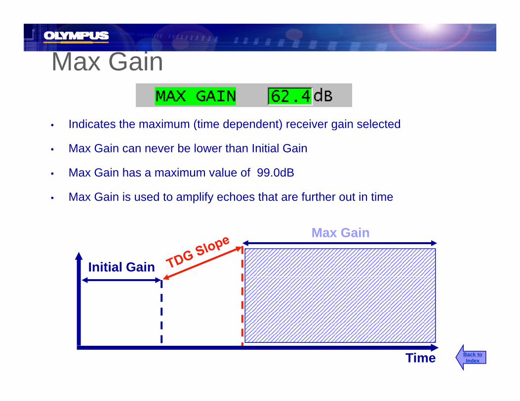
Max Gain
• Indicates the maximum (time dependent) receiver gain selected• Indicates the maximum (time dependent) receiver gain selected
• Max Gain can never be lower than Initial Gain
• Max Gain has a maximum value of 99.0dBMax Gain has a maximum value of 99.0dB
• Max Gain is used to amplify echoes that are further out in time
Initial Gain
Max Gain
Time Back toIndex

Initial Gain
• Indicates the initial (time dependent) receiver gain selected( p ) g
• Amplifies echoes close to the Main Bang or Interface Echoes
• Initial Gain starts at time zero and extends to:
• Main Bang Blank in Mode 1
• The end of the Interface Blank in Mode 2 and Mode 3
Initial Gain
Max Gain
Time Back toIndex

TDG Slopep
• The rate of increase of the receiver gain (time dependent) from Initial Gain to Max Gain
• Slope can help suppress reflections from grain structure or fibers• Slope can be adjusted from 0.0dB to 26.52 dB/µSec• The point in time that the gain starts to slope is:
• The Main Bang Blank in Mode 1• The End of the Interface Blank in Mode 2 and Mode 3
Initial Gain
Max Gain
Time Back toIndex

TDG Gain Mode 1
InitialMax Gain
Initial Gain
Back toIndex

TDG Gain Mode 2 and Mode 3
Initial Gain
Max Gain
MBB
Back toIndex
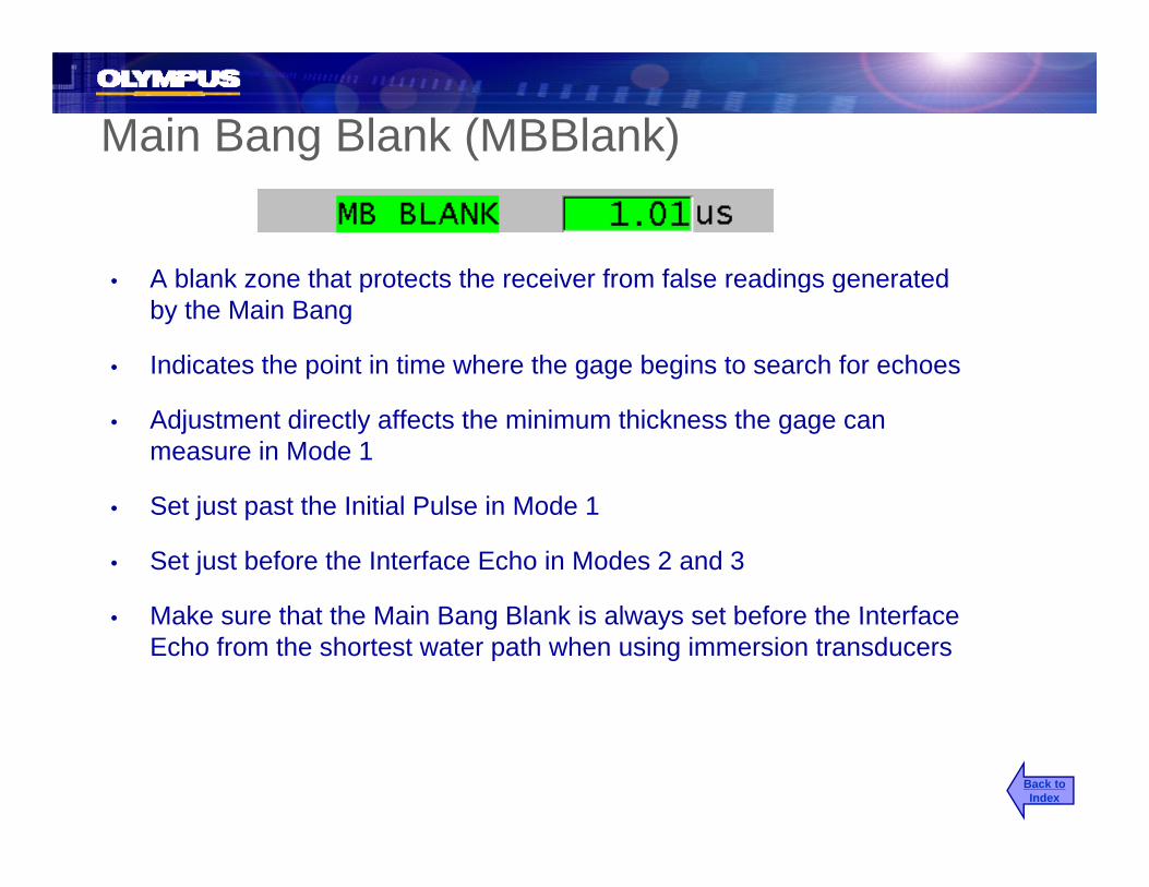
Main Bang Blank (MBBlank)
A blank zone that protects the receiver from false readings generated• A blank zone that protects the receiver from false readings generated by the Main Bang
• Indicates the point in time where the gage begins to search for echoes
• Adjustment directly affects the minimum thickness the gage can measure in Mode 1
S t j t t th I iti l P l i M d 1• Set just past the Initial Pulse in Mode 1
• Set just before the Interface Echo in Modes 2 and 3
Make sure that the Main Bang Blank is always set before the Interface• Make sure that the Main Bang Blank is always set before the Interface Echo from the shortest water path when using immersion transducers
Back toIndex

MBBlank in Mode 1
BackMain Bang
Blank
Back wall Echo
InitialP lPulse
Back toIndex
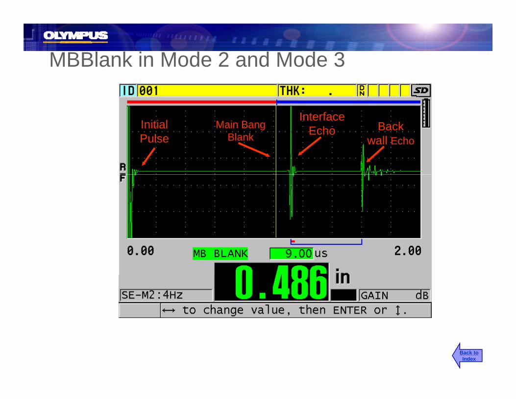
MBBlank in Mode 2 and Mode 3
Main BangInitialInterface
BackMain Bang Blank
InitialPulse
Echo Back wall Echo
Back toIndex

Echo Window
• Defined as the time between:
• The Main Bang Blank and the Echo Window in Mode 1The Main Bang Blank and the Echo Window in Mode 1
• The end of the Interface Blank and the Echo Window in Mode 2 or Mode 3
• Indicates the selected period of time in which the receiver will search for echoes
• Signal appearing after (i.e. outside of) the Echo Window will not be detected by the gage
Back toIndex

Echo Window in Mode 1
Main Bang Blank Echo
Window
Initial Back wall InitialPulse Echo
Back toIndex

Echo Window in Mode 2 and Mode 3Echo Window in Mode 2 and Mode 3
E hInterface
Echo
Echo Window
Back wall 2nd
I t fEcho Interface Echo
Back toIndex

Echo 1 Detect
• This indicates the detection polarity of the "first detected back wall signal" in the Echo Window in Mode 1
• In Modes 2 &3 it refers to detection polarity of Interface (or delay line)In Modes 2 &3 it refers to detection polarity of Interface (or delay line) Echo
• Always choose the detection polarity on the singular lobe of the echo
• Echo polarity is affected by:
• Acoustic impedance
E h di t ti b d b i t t i t l fib d• Echo distortion can be caused by grain structure, internal fibers, and surface conditions
Back toIndex

Echo 1 Detect
Negative Detection Positive Detection Plastic Steel Back by Air Bonded to Steel
Back toIndex

Echo 2 Detect (Modes 2 and 3 only)
• Indicates the detected polarity of the back wall echo in Mode 2 or the pair
( y)
p y pof back wall echoes in Mode 3
• Always choose the detection polarity on the singular lobe of the echo
Echo 1 DetectPositive
Echo 2 DetectNegative
Back toIndex

Interface Blank (Modes 2 and 3 only)( y)
• Sets the length of a blank that follows the detected interface echo
• Used to prevent the gage from detecting the trailing edge of the Interface Echo in Mode 2
Used to select which pair of back wall echoes will be detected in Mode 3• Used to select which pair of back wall echoes will be detected in Mode 3
Back toIndex
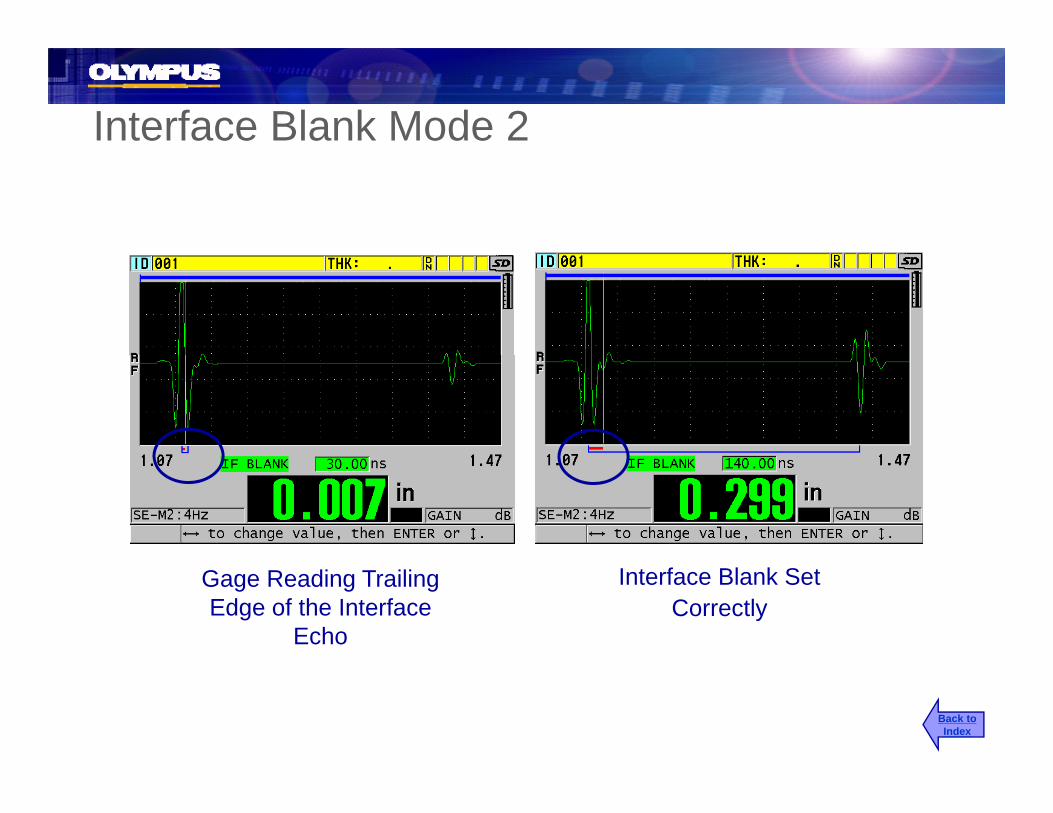
Interface Blank Mode 2
Gage Reading Trailing Edge of the Interface
Echo
Interface Blank Set Correctly
Back toIndex

Interface Blank Mode 3
Gage Reading between Back Wall 1 and 2
Gage Reading between Back Wall 2 and 3
Back toIndex

Mode 3 Blank (Mode 3 only)
• Sets the length of a blank that follows the first detected back wall echo in Mode 3
U d t t th f d t ti th t ili d f th fi t b k ll h• Used to prevent the gage from detecting the trailing edge of the first back wall echo
Back toIndex

Mode 3 Blank (Mode 3 only)( y)
Gage Hanging Up on Trailing Edge of Back Wall 1
Mode 3 Blank Set Properly
Back toIndex

38DL PLUS Custom Dual Element Transducer S tSetups
Back toIndex
Custom Transducer Setup for Non Standard Dual Transducers
The 38DL PLUS offers probe recognition for the Olympus’ standard D79XThe 38DL PLUS offers probe recognition for the Olympus standard D79X series dual element transducers. When one of these dual element transducers is plugged into the 38DL PLUS the gage automatically recalls a default setup and V-Path correction.
These D79X series transducers will provide superior performance when used with the 38DL PLUS. The gage . The gage also has the ability to create and store custom setups for non standard dual element transducers, including a custom V-Path correctioncustom V Path correction.
Back toIndex

Caution for Non Center Pin DualsOlympus cannot guarantee measurement accuracy or performance for transducers other than our standard D79X dualsPerformance, accuracy and minimum/maximum thickness capability with other duals
Caution for Non Center Pin Duals
y yneeds to be verified by the userTransducers that work in standard mode (first back wall) may not work very well in Echo-to-Echo modeThe 38DL PLUS is designed to work with most dual element transducers that are used for thickness gauging applications, but there is no guarantee that it will work with all dual element transducers
D790 on 0.200 in. Block Other 5 MHz Dual on 0.200 in. Block Back toIndex

Non Standard Dual Element TransducersNon Standard Dual Element TransducersWhen a user plugs in a dual element transducer that is not an Olympus D79X transducer. The 38DL PLUS will display the generic dual element transducer setup
l tiselection screen
Use [ ],[ ] to highlight “Default” to select from the list generic dual element transducer or “Custom” to select for the list of previously stored custom dual element setups.
Note: When selecting a generic setup, choose the one that best matches the frequency of the transducer being used.
Back toIndex
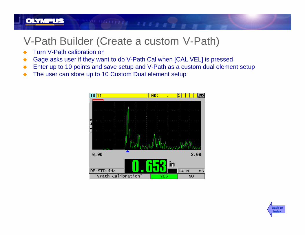
V-Path Builder (Create a custom V-Path)V Path Builder (Create a custom V Path)Turn V-Path calibration onGage asks user if they want to do V-Path Cal when [CAL VEL] is pressedEnter up to 10 points and save setup and V-Path as a custom dual element setup The user can store up to 10 Custom Dual element setupThe user can store up to 10 Custom Dual element setup
Back toIndex

Creating a Custom Dual Transducer SetupCreating a Custom Dual Transducer SetupUse the [ ],[ ] keys to select a generic setup from the list of default dual elementfrom the list of default dual element transducers and press [MEAS]:
2nd FDo-ZERO
CALZERO
Press then
To zero the transducer
Back toIndex

Creating a Custom Dual Transducer SetupCreating a Custom Dual Transducer Setup•Adjust the range of waveform so the echoes from the upper thickness limit can be seen on screen•Couple to your thick and thin test standards and adjust the gain so that the proper p y j g p pecho detection is being made on the min and max thickness
Note: the thickness measurement value at this point will most likely not be correct
Back toIndex

Two Point Calibration ( Cal VEL & Cal Zero)( )•Couple to the thick step, get a steady reading and press [Cal VEL], then [ENTER], then enter in the known thickness•Couple to the thin step, get a steady reading press [Cal VEL], then [ENTER], then enter in the known thickness and press [MEAS]enter in the known thickness and press [MEAS]• Check the thickness on all steps if measurement accuracy is sufficient then save the setup as a custom dual element transducer setup.
Note: If the accuracy is not acceptable then a custom V-Path should be performedNote: If the accuracy is not acceptable then a custom V Path should be performed.
Back toIndex

Turn V-Path Builder onTurn V Path Builder onSP MENU
SETUPMENU
Press MENU
Use the [ ],[ ] keys to select MEAS, then press [ENTER]
Use the [ ],[ ] keys to highlight V-Path CAL Enable and use the [ ] [ ] to turn it on then press the[ ],[ ] to turn it on, then press the [MEAS]
Back toIndex

V-Path Builder (Create a custom V-Path)V Path Builder (Create a custom V Path)When V-Path builder is turned on the 38DL PLUS will ask the user if they want to perform a V-Path calibration when the [Cal VEL] is pressed.
V-Path builder requires at least three calibration points and allows the user to enter up to 10 calibration points to create a custom V-Path
Points should all be within the measurement range and should represent the min and thi k t b dmax thickness to be measured.
Back toIndex
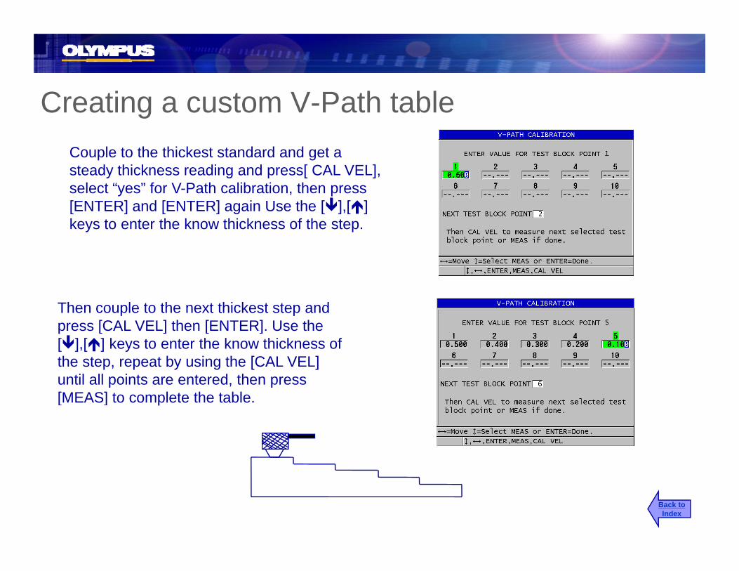
Creating a custom V-Path tableCreating a custom V-Path tableCouple to the thickest standard and get a steady thickness reading and press[ CAL VEL], y g p [ ]select “yes” for V-Path calibration, then press [ENTER] and [ENTER] again Use the [ ],[ ]keys to enter the know thickness of the step.
Then couple to the next thickest step and [CAL VEL] th [ENTER] U thpress [CAL VEL] then [ENTER]. Use the
[ ],[ ] keys to enter the know thickness of the step, repeat by using the [CAL VEL] until all points are entered, then press [MEAS] t l t th t bl[MEAS] to complete the table.
Back toIndex
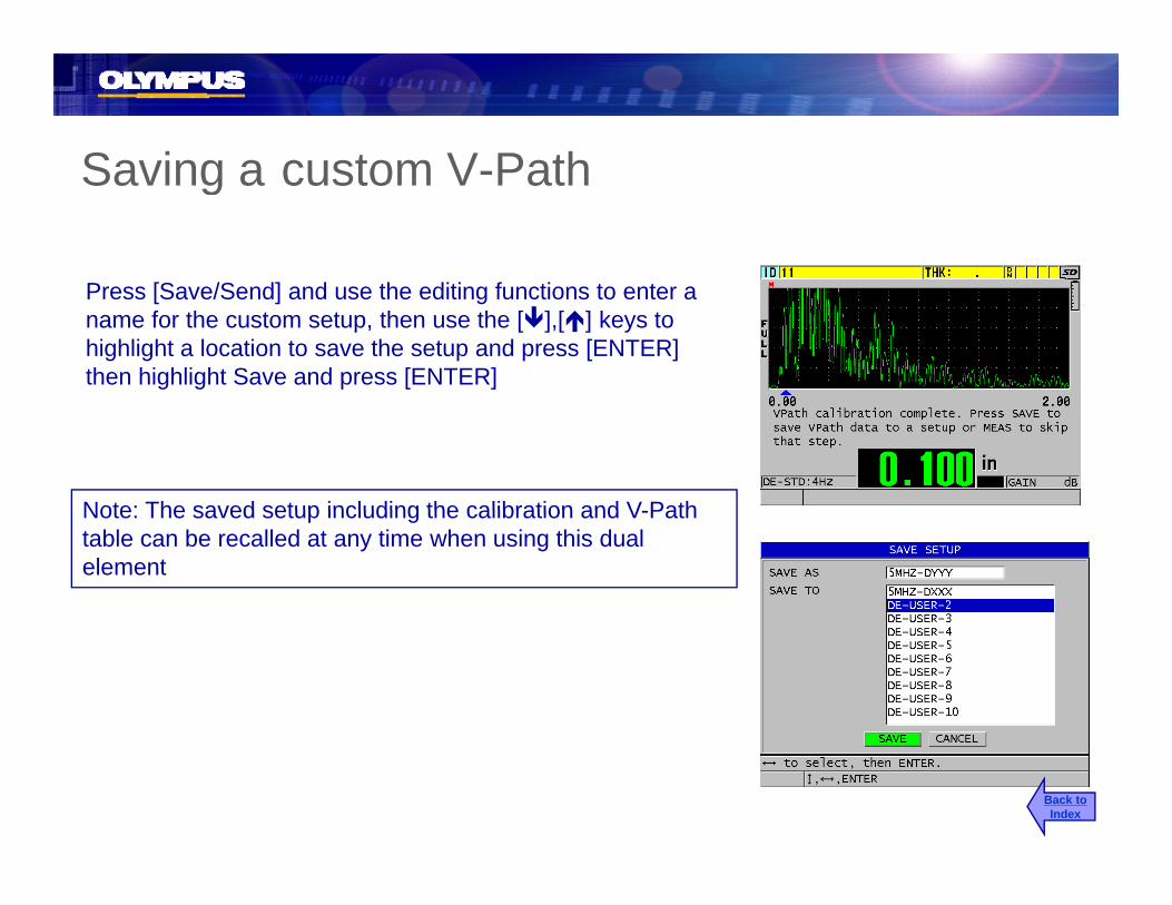
Saving a custom V PathSaving a custom V-Path
Press [Save/Send] and use the editing functions to enter a name for the custom setup, then use the [ ],[ ] keys to highlight a location to save the setup and press [ENTER] then highlight Save and press [ENTER]
Note: The saved setup including the calibration and V PathNote: The saved setup including the calibration and V-Path table can be recalled at any time when using this dual element
Back toIndex

38DL PLUS Velocity and Time of Flight Measurements
Back toIndex

Velocity MeasurementsVelocity MeasurementsThe 38DL PLUS has the ability to be make thickness, Velocity or time of flight. The user can select the measurement mode in the Setup menu
PressSP MENU
SETUPMENU
Use the [ ],[ ] to highlight [ ],[ ] g g“MEAS” then press [ENTER]
Use the [ ],[ ] to highlight Measurement Mode then Use [ ],[ ] to select Velocimeter then press [MEAS]p [ ]
Back toIndex

Making Velocity MeasurementsMaking Velocity MeasurementsWhen in velocity mode it is necessary to perform a two point thickness calibration to properly set the zero offset for the transducer being used.
•Once calibrated couple to a sample of known thickness
•The gage will display a velocity based on the current REF Thickness value
•Press [2nd F],[XDCR RECAL] (REF ) fVALUE) and enter the know thickness of
the sample and press [ENTER]
Note: To save velocity measurement to the datalogger you need to make sure gg yyou create a file with the file data type set as “Velocity”.
Back toIndex

Time of Flight MeasurementsTime of Flight MeasurementsThe 38DL PLUS has the ability to be make thickness, velocity or time of flight. The user can select the measurement mode in the Setup menu
PressSP MENU
SETUPMENU
Use the [ ],[ ] to highlight [ ],[ ] g g“MEAS” then press [ENTER]
Use the [ ],[ ] to highlight Measurement Mode then Use [ ],[ ] to select Time of Flight then press [MEAS]
Back toIndex

Making Time of Flight MeasurementsMaking Time of Flight MeasurementsWhen in time of flight mode it is necessary to perform a two point thickness calibration to properly set the zero offset for the transducer being used.
•Once calibrated couple to a sample of known thickness
•The gage will display a two way time of flight for the material
Note: To save velocity measurement to the datalogger you need to make sure you create a file with the file data type as “Time of Flight”
Back toIndex

38DL PLUS Software options38DL PLUS Software options
•High Resolution (HR) Software Option
•Internal Oxide Software Option
•High Penetration (HP) Software Option
•Multi-Layer (MM) Software Option•Multi-Layer Calibration
Back toIndex

Activating Software OptionsActivating Software Options
•The software options for the 38DL PLUS are activated using a licensed option key. An option can be purchased at the time the unit is purchased or the 38DL PLUS can be upgraded with the software options in the field If the unit was purchased along with softwareoptions in the field. If the unit was purchased along with software options then they will be installed and activated when you receive it.
•If software options are needed after the unit is purchased then they will have to be activated using a unique licensed option keyhave to be activated using a unique licensed option key.
•Please contact your Olympus representative for information concerning activating software options for your 38DL PLUS
Back toIndex
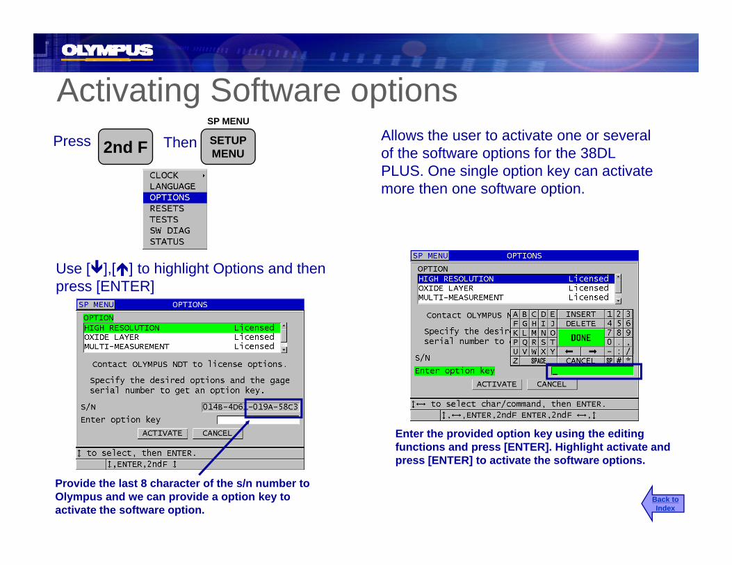
Activating Software optionsg pPress 2nd F
SP MENU
SETUPMENU
Then Allows the user to activate one or several of the software options for the 38DL PLUS. One single option key can activate PLUS. One single option key can activate more then one software option.
Use [ ],[ ] to highlight Options and then press [ENTER]
Enter the provided option key using the editing functions and press [ENTER]. Highlight activate and press [ENTER] to activate the software options
Provide the last 8 character of the s/n number to Olympus and we can provide a option key to activate the software option.
press [ENTER] to activate the software options.
Back toIndex

38DL PLUS High Resolution Software Option
Back toIndex
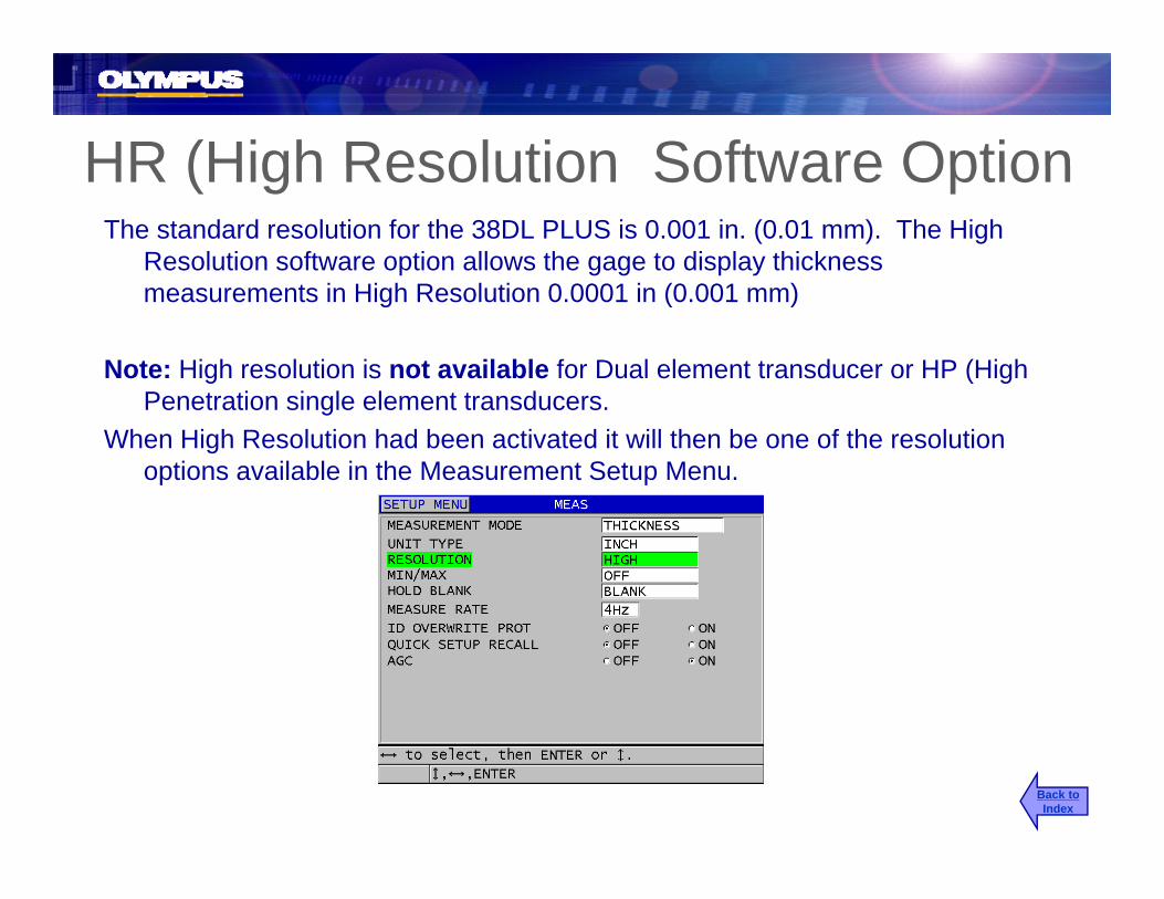
HR (High Resolution Software OptionHR (High Resolution Software OptionThe standard resolution for the 38DL PLUS is 0.001 in. (0.01 mm). The High
Resolution software option allows the gage to display thickness measurements in High Resolution 0.0001 in (0.001 mm)
Note: High resolution is not available for Dual element transducer or HP (High P t ti i l l t t dPenetration single element transducers.
When High Resolution had been activated it will then be one of the resolution options available in the Measurement Setup Menu.
Back toIndex

38DL PLUS Internal Oxide Software Option
Back toIndex

Oxide Software OptionOxide Software Option
• Oxide/Scale can build up on the inside of boiler tubes• Oxide/Scale can build up on the inside of boiler tubes• The oxide that builds up acts as an insulator.• This effects the heat transfer from outside of the tube to the water inside the
tubetube• The tubes runs at a higher temperature then they were designed for and they
start to thin faster.• Knowing both the thickness of the steel and Internal Oxide the remaining g g
tube life can be more accurately predicted
Back toIndex

Oxide/Scale MeasurementOxide/Scale Measurement• New measurement algorithm allows the user to measure scale or oxide build up on the inside of boiler tubes
• Thickness of Oxide helps predict tube life
• Measures and displays Oxide and tube thickness at the same time
• Min scale thickness
•0.010 in. (0.25mm ) with M2017
•0.006 in. (0.150 mm) with M2091 Normal Incident Shear
Steel/Oxide Echo
Interface Echo
Echo frominside of oxide
Steel/OxideEcho Marker
Data Window
Back toIndex
Oxide ThicknessTube Thickness
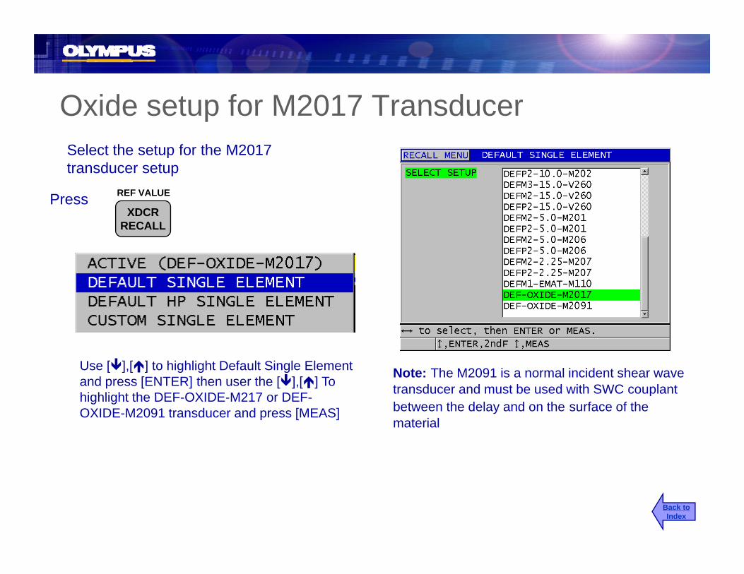
Oxide setup for M2017 TransducerOxide setup for M2017 TransducerSelect the setup for the M2017 transducer setup
Press REF VALUE
XDCRRECALL
Note: The M2091 is a normal incident shear wave transducer and must be used with SWC couplant
Use [ ],[ ] to highlight Default Single Element and press [ENTER] then user the [ ],[ ] To highlight the DEF OXIDE M217 or DEF p
between the delay and on the surface of the material
highlight the DEF-OXIDE-M217 or DEF-OXIDE-M2091 transducer and press [MEAS]
Back toIndex

Adjust the Initial Gain, Slope and Max GainAdjust the Initial Gain, Slope and Max GainAdjust the TVG Gain (Initial, Max Gain and Slope) to make a mode 2 detection of the larger total backdetection of the larger total back wall.
Oxide/SteelInterface EchoInterface Echo
Total back wall
Mode 2 detection
echo
Mode 2 detectionfrom delay line echo to total back wall echo Back to
Index

Adjust Data Window1Adjust Data Window1Adjust the DataWin1 so it extends far enough to cover the oxide steel interface echo
Oxide/SteelInterface Echo
Back toIndex

Oxide: Steel Cal VelocityOxide: Steel Cal Velocity
Couple transducer to thick steel sample without oxide
Allows the user to calibrate for the speed of d f th t i l t b t t d U llwithout oxide
Presssound of the material to be tested. Usually done on a sample representing the maximum of the measurement range.
VEL
CALVEL
Once reading is steady
Uncouple the transducer and
PressENTER
Uncouple the transducer and enter the known thickness using the
Back toIndex

Oxide: Steel Cal ZeroOxide: Steel Cal ZeroOxide: Steel Cal ZeroOxide: Steel Cal ZeroA subtracted time measurement used to compensate for the transit time through the delay line in the transducer and the
Couple transducer to the thin steel sample without oxide
D ZERO
Press
delay line in the transducer and the couplant layer. Cal Zero is usually done on a sample representing the minimum of your measurement range.
Do-ZERO
CALZERO
Once reading is steady
Press ENTER
Uncouple transducer and enter the k thi k Th [CAL] tknown thickness. Then press [CAL] to calibrate for the velocity of the oxide.
Back toIndex

Oxide Coating CalibrationOxide Coating Calibration
Couple transducer to a sample with known oxide thickness
Allows the user to calibrate for the sound speed of the of the oxide material.
Press VEL
CALVEL
Once reading is steady P
Uncouple the transducer and
PressENTER
Uncouple the transducer and enter the known oxide thicknessPress [MEAS]
Back toIndex
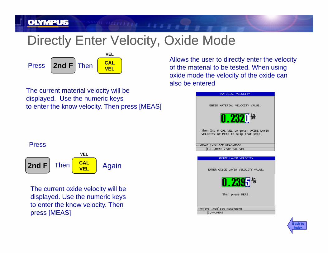
Directly Enter Velocity, Oxide ModeDirectly Enter Velocity, Oxide Modey yy yAllows the user to directly enter the velocity of the material to be tested. When using oxide mode the velocity of the oxide can
Press 2nd FVEL
CALVELThen
yalso be entered
The current material velocity will bedisplayed. Use the numeric keysto enter the know velocity. Then press [MEAS]
PPress
Again2nd FVEL
CALVELThen
The current oxide velocity will bedisplayed. Use the numeric keysto enter the know velocity. Thento enter the know velocity. Thenpress [MEAS]
Back toIndex

Oxide Software SetupOxide Software SetupOxide Software SetupOxide Software Setup
PressAllows the user to select if they want to display the thickness of the Oxide or Boiler tube in thickness or time of flight and they can also
SP MENU
SETUPMENU g y
select which measurement is displayed in large font.
Use the [ ],[ ] to highlight “Oxide Options” then press [ENTER] to display the Oxide Measure Type setup screen. Use [ ],[ ] to highlight the parameter and [ ],[ ] to adjust it then press [ENTER]
Back toIndex

38DL PLUS HP Software Option
Back toIndex

HP transducer setupsHP transducer setupsOnce the HP (High Penetration) software has been activated the 38DL PLUS will add a list of
PressREF VALUE
XDCRRECALL
HP low frequency single element transducers to the list of default single element transducers.
Use [ ],[ ] to highlight Default HP Single Element and press [ENTER] then user the [ ] [ ] to highlight any of theuser the [ ],[ ] to highlight any of the default low frequency transducer setup and press [MEAS].
Back toIndex

Measurements with The M2008Measurements with The M2008The M2008 is a special low frequency transducer that is used to measure thick fiberglass and
Press 2nd FVEL
CALThen composite materials. Especially good for material 0.200 in. (6 mm) and greater. When using this transducer it is necessary to Zero the delay line.
Press 2nd F VELThen
M2008 on thick fiberglassBack toIndex

38DL PLUS Multi Layer Software Option
Back toIndex

Multi-Layer Software OptionMulti Layer Software OptionThe Multi-Layer software option is used to simultaneously display the thickness of up to fourlayers of a multi-layer material.layers of a multi layer material.
Some common applications are:
Multi Layer plastic fuel tanksMulti-Layer plastic fuel tanks
Multi-Layer plastic bottle preforms
Multi-Layer aircraft windows
Calculate the radius of curvature and the thickness of contact lenses
Co-extruded plastic
Two layer hot tubs and spasy p
Back toIndex

Multi-Measure SetupMulti Measure SetupOnce activated this software option allows the user to select up to four custom stored transducer setups and display all the thickness readings on
Press SP MENU
SETUPMENU setups and display all the thickness readings on
the display at one time. A custom transducer setup has to be made for each layer of the material to be measured.
MENU
Uses the [ ],[ ] to highlight the setup type and press [ENTER]setup type and press [ENTER]
Uses the [ ],[ ] to highlight the parameter and type and press
Back toIndex
parameter and type and press [ENTER]

Multi Measure Mode (Normal Mode)Multi-Measure Mode (Normal Mode)
U [ ] [ ] t hi hli ht th
Used to measure an application consisting of multiple layers
Use [ ],[ ] to highlight the parameter and [ ],[ ] to change the parameter
Enable: Turns Multi-Measure function – On/OffMode: Select (Normal, Soft Contact, or Pct Total Thk)S M d M th ti l f l t d l O /OffSum Mode: Mathematical sum of selected layers – On/OffDisplay: Select (Waveform or Large Font) [see next slide]Save/Send Key: Select (Active or Auto-Incr Active)Setup 1 - 4: User selected custom setups for each layerS ti If S M d i O l t l t (S t 1 3)Summation: If Sum Mode is On, select layers to sum (Setup 1 - 3)
Back toIndex

Multi-Measure ModeMulti-Measure ModeDisplay Parameter (Waveform vs. Large Font)
Display set to Waveform Display set to Large Font
Back toIndex

Multi-Measure Mode (Soft Contact)Multi-Measure Mode (Soft Contact)Used to measure the layers of a soft contact lens application
U [ ] [ ] t hi hli ht th
contact lens application
Use [ ],[ ] to highlight the parameter and [ ],[ ] to change the parameter
Enable: Turns Multi-Measure function – On/OffMode: Select (Normal, Soft Contact, or Pct Total Thk)Display: Select (Waveform or Large Font)Display: Select (Waveform or Large Font)Save/Send Key: Select (Active or Auto-Incr Active)SGTTL HT: Select custom setup saved for sagittal heightLENS THK: Select custom setup saved for lens thickness PDSTL DIA: Enter diameter of pedestalPDSTL DIA: Enter diameter of pedestal
Back toIndex

Multi-Measure Mode (Percent Total Thickness)Multi Measure Mode (Percent Total Thickness)
Used to express the thickness of a layer as a percentage of the total
Use [ ],[ ] to highlight the
y p gthickness of a part
Use [ ],[ ] to highlight the parameter and [ ],[ ] to change the parameter
Enable: Turns Multi-Measure function – On/OffMode: Select (Normal, Soft Contact, or Pct Total Thk)Display: Select (Waveform or Large Font)Save/Send Key: Select (Active or Auto-Incr Active)Setup 1 - 3: User selected custom setups for each layerTotal: Choose layers to be part of the total thicknessShow Total: Select to show total thickness when measuringShow as %: Choose which layers to display as a percentage
Back toIndex

Data Window 1 (Barrier Layer only)Data Window 1 (Barrier Layer only)Data Window 1 (Barrier Layer only)Data Window 1 (Barrier Layer only)
• Only available in Barrier Layer measurement type
• Used in Mode 1 to setup a gate on the Barrier Layer echo. The gage automatically centers DataWin1 on the detected Barrier Layer echo Theautomatically centers DataWin1 on the detected Barrier Layer echo. The width of DataWin1 should be set so the entire echo is within the gate.
• Used in Mode 2 to setup a gate on the Interface/Surface echo. The gage automatically centers DataWin1 on the Interface/Surface echo. The width ofautomatically centers DataWin1 on the Interface/Surface echo. The width of DataWin1 should be set so the entire echo is within the gate.
Note: In Mode 2 the echo in DataWin1 is used as a reference echo for the advanced algorithmthe advanced algorithm.
Back toIndex

Data Window 2 (Barrier Layer only)Data Window 2 (Barrier Layer only)Data Window 2 (Barrier Layer only)Data Window 2 (Barrier Layer only)
• Only available in Barrier Layer measurement type and Mode 2
• In Mode 2 it is used to setup a gate on the Barrier Layer echo. The gage automatically centers DataWin2 on the detected Barrier Layer echo The widthautomatically centers DataWin2 on the detected Barrier Layer echo. The width of DataWin2 should be set so the entire echo is within the gate.
Back toIndex
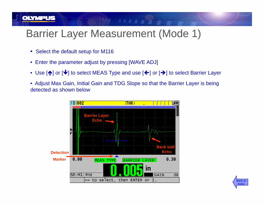
Barrier Layer Measurement (Mode 1)Barrier Layer Measurement (Mode 1)• Select the default setup for M116
• Enter the parameter adjust by pressing [WAVE ADJ]
y ( )y ( )
Enter the parameter adjust by pressing [WAVE ADJ]
• Use [ ] or [ ] to select MEAS Type and use [ ] or [ ] to select Barrier Layer
• Adjust Max Gain, Initial Gain and TDG Slope so that the Barrier Layer is being detected as shown belowdetected as shown below
Barrier LayerBarrier Layer Echo
Back wallEchoDetection
Marker
Back toIndex

Barrier Layer Measurement (Mode 1)Barrier Layer Measurement (Mode 1)
Use [ ] or [ ] to select DataWin1 and use [ ] or [ ] adjust the width so it is large enough to include the entire Barrier Layer reflection but not include the Main Bang
Barrier Layer Measurement (Mode 1)Barrier Layer Measurement (Mode 1)
enough to include the entire Barrier Layer reflection, but not include the Main Bang echo or Back wall echo.
Barrier Layer Echo
DataWin1Back wall
Echo
Back toIndex

Barrier Layer Measurement (Mode 2)Barrier Layer Measurement (Mode 2)• Select the default setup for M208
• Enter the parameter adjust by pressing [WAVE ADJ]
y ( )y ( )
Enter the parameter adjust by pressing [WAVE ADJ]
• Use [ ] or [ ] and [ ] or [ ] to make sure Mode 2 is selected and the Meas Type is set to Barrier Layer. Adjust Max Gain, Initial Gain, TDG Slope, Echo 1 and Echo 2 polarity so a proper detection is being made between the Interface echo and the Barrier Layer echo as shown below.
Interface BarrierInterfaceEcho
BarrierEcho
Back wallEcho
Mode Detection
M kMarker
Back toIndex

Barrier Layer Measurement (Mode 2)Barrier Layer Measurement (Mode 2)
• Use [ ] or [ ] to select DataWin1 and use [ ] or [ ] to adjust the width so it is large enough to include the entire Interface echo but does not include the Main Bang
y ( )y ( )
or the Barrier echo.
• Use [ ] or [ ] to select DataWin2 and use [ ] or [ ] to adjust the width so that the width of the window is large enough to include the entire Barrier Layer reflection, but does not include the Interface echo or Back wall echodoes not include the Interface echo or Back wall echo.
Interface Barrier LayerInterface Echo
Barrier LayerEcho
DataWin1 DataWin2Back wall
Echo
Back toIndex

38DL PLUS38DL PLUSMulti-Layer Calibration
Back toIndex

Cal Velocity (Standard Measurement Type)Cal Velocity (Standard Measurement Type)y ( yp )y ( yp )Couple transducer to the thick sample Allows the user to calibrate for the speed of
Press
psound of the material to be tested. Usually done on a sample representing the maximum of the measurement range.
VEL
CALVEL
Once reading is steady
Press ENTER
Uncouple the transducer andenter the known thickness
Back toIndex

Cal Zero (Standard Measurement Type)Cal Zero (Standard Measurement Type)Cal Zero (Standard Measurement Type)Cal Zero (Standard Measurement Type)A subtracted time measurement used to compensate for the transit time through the
Couple transducer to the thin sample
Pressdelay line in the transducer and the couplant layer. Cal Zero is usually done on a sample representing the minimum of your measurement range.
Do ZERO
CALZERO
Once reading is steady
PressENTER
Uncouple transducer and enter theUncouple transducer and enter the known thickness. Then press the [MEAS] key to complete the calibration.
Back toIndex

Cal Mode 1 (Barrier Measurement Type)Cal Mode 1 (Barrier Measurement Type)
Allows the gage to store a reference h ff t t bl k d lib t f
PressVEL
CALVEL
Couple transducer to 0.50 in. or 15 mm test block
echo off a test block and calibrate for the sound speed of the barrier material to be tested.
Couple to a sample with known barrier
Press ENTER
Couple to a sample with known barrier thickness
PressVEL
CALVEL
Then ENTER
Enter the known thickness for the barrier layer thickness and press [MEAS]
VEL
Back toIndex
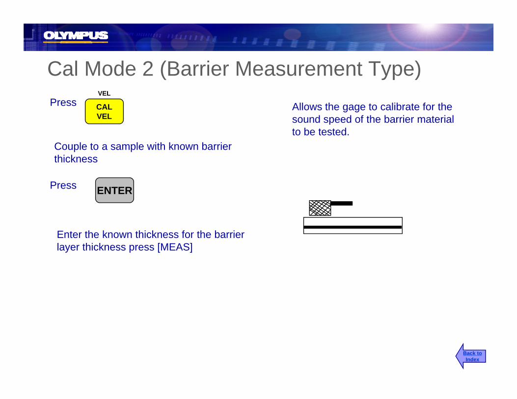
Cal Mode 2 (Barrier Measurement Type)Allows the gage to calibrate for the sound speed of the barrier material
Cal Mode 2 (Barrier Measurement Type)Press
VEL
CALVEL
Couple to a sample with known barrier thickness
pto be tested.
Press ENTER
Enter the known thickness for the barrier layer thickness press [MEAS]
Back toIndex