365nm uvc led - boselec.com
TRANSCRIPT
365nm UVC LED
violumas.com
violumasHigh Power UV LED Solutions
www.boselec.com [email protected]
shop.boselec.com 617.566.3821
• SMDo low, medium & high power
• Chip on Board (COB)• Light Bars (12x1)

365nm UVA LED
Contents
SMD• medium power - 775 mW, 60 deg.• high power - 2850 mW, 90 deg.
COB • medium power• high power• 12 x 1 light bar
www.boselec.com | [email protected] | shop.boselec.com | 617.566.3821
Driver Board • UPS Driver
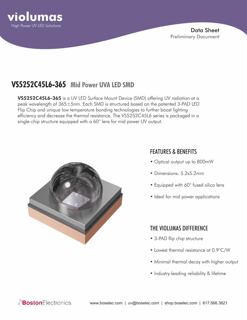
VS5252C45L6-365 Mid Power UVA LED SMD
VS5252C45L6-365 is a UV LED Surface Mount Device (SMD) offering UV radiation at a peak wavelength of 365±5nm. Each SMD is structured based on the patented 3-PAD LED Flip Chip and unique low temperature bonding technologies to further boost lighting efficiency and decrease the thermal resistance. The VS5252C45L6 series is packaged in a single-chip structure equipped with a 60° lens for mid power UV output.
• Optical output up to 800mW
• Dimensions: 5.2x5.2mm
• Equipped with 60° fused silica lens
• Ideal for mid power applications
FEATURES & BENEFITS
• 3-PAD flip chip structure
• Lowest thermal resistance at 0.9°C/W
• Minimal thermal decay with higher output
• Industry-leading reliability & lifetime
THE VIOLUMAS DIFFERENCE
Data Sheet
violumasHigh Power UV LED Solutions
Preliminary Document
www.boselec.com | [email protected] | shop.boselec.com | 617.566.3821

Mid Power UVA LED SMDviolumas VS5252C45L6-365
Electro-Optical Characteristics at T=25°C and IF =700mA
Parameter Symbol Unit Min Typical Max
Peak Wavelength λP nm
VFForward Voltage
360 365 370
Radiant Flux
Full Width of Half Magnitude
Radiant Angle
Thermal Resistance, Junction to Solder Joint
PO
∆λ
2Φ1/2
Rth(J-S)
V - 4.1 -
mW 750 775 800
nm - 12 -
Degree - 60 -
°C/W - 0.9 -
Parameter Symbol Unit Value
Absolute Maximum Ratings
Test Condition Test Duration Test Failed/Tested
Reliability
Forward Current
Reverse Voltage
Power
Junction Temperature
Operating Temperature
Storage Temperature
IF
VR
PO
TJ
TOPR
TSTG
mA
V
W
°C
°C
1000
5
4.2
115
-30 ~ 80
°C -40 ~ 100
Operating Temperature
Storage Temperature
-45°C ~ 125°C
IF =350mA, T=25°C
200 Cycles
1000 Hours
0/10
0/10
www.boselec.com | [email protected] | shop.boselec.com | 617.566.3821
Mid Power UVA LED SMDviolumas VS5252C45L6-365
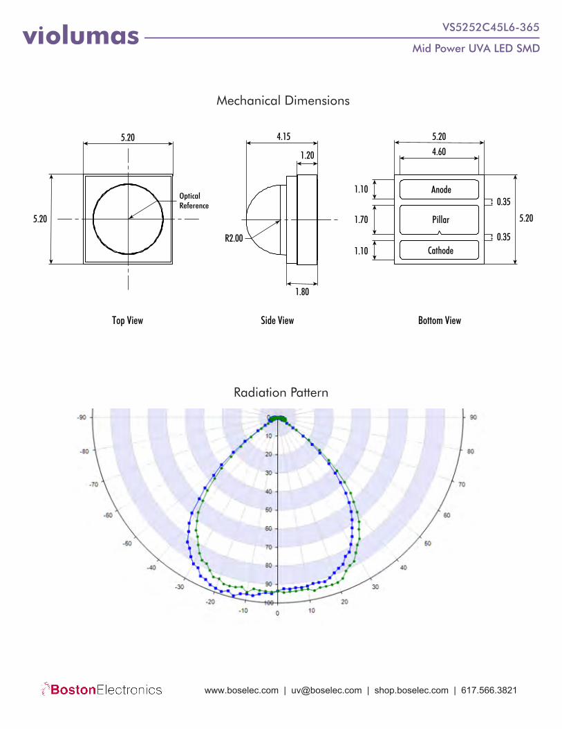
Mechanical Dimensions
Radiation Pattern
Top View Side View Bottom View
5.20
5.20
Optical Reference
4.15
1.20
1.80
R2.00
5.20
Anode
Pillar
Cathode
1.10
4.60
0.35
1.70
1.100.35
5.20
www.boselec.com | [email protected] | shop.boselec.com | 617.566.3821
Mid Power UVA LED SMDviolumas VS5252C45L6-365
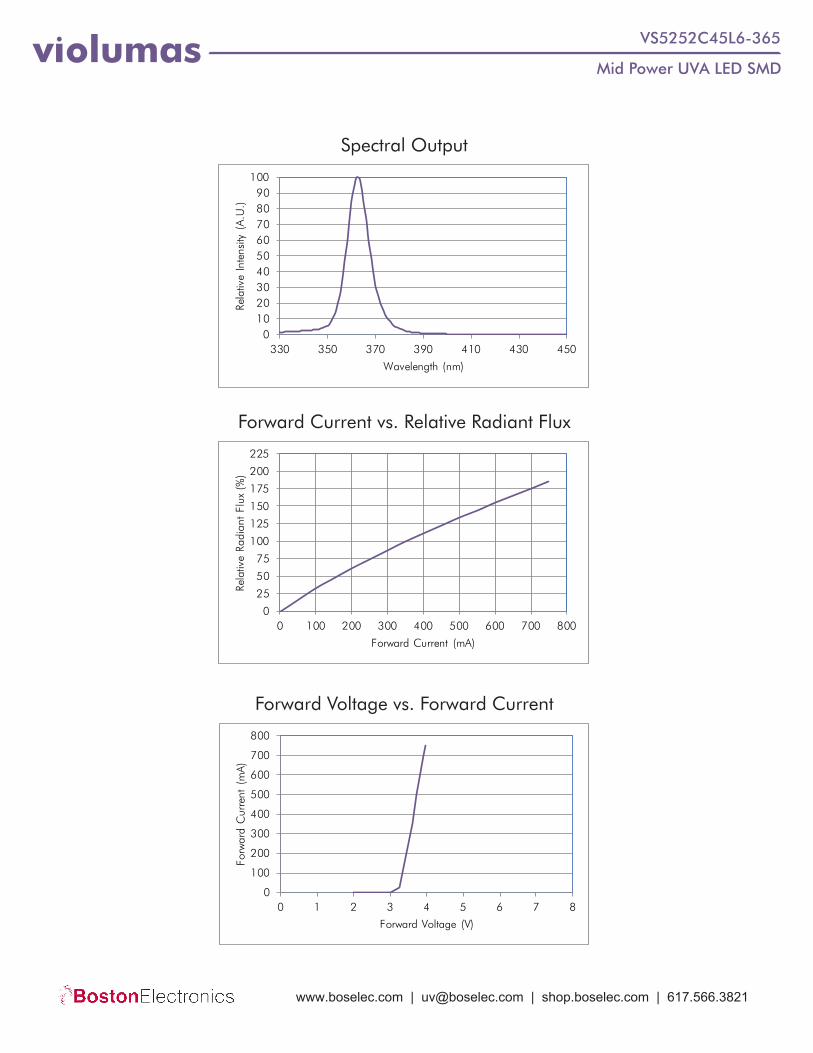
Forward Current vs. Relative Radiant Flux
Forward Voltage vs. Forward Current
Spectral Output
0102030405060708090
100
330 350 370 390 410 430 450
Rela
tive
Inte
nsity
(A
.U.)
Wavelength (nm)
0
25
50
75
100
125
150
175
200
225
0 100 200 300 400 500 600 700 800
Rela
tive
Radi
ant
Flux
(%
)
Forward Current (mA)
0
100
200
300
400
500
600
700
800
0 1 2 3 4 5 6 7 8
Forw
ard
Cur
rent
(m
A)
Forward Voltage (V)
www.boselec.com | [email protected] | shop.boselec.com | 617.566.3821

Mid Power UVA LED SMDviolumas VS5252C45L6-365
Handling & Usage Precautions• Exhibit extreme care when handling LEDs. Do not touch the LED with bare hands as doing so may contaminate and
affect the optical characteristics of the LED. When using tweezers, do not apply excessive force, especially to theglass lens. Do not drop the LED as doing so may cause product damage.
• Ensure that electrostatic discharge specifications are followed. Static electricity and surge voltages may causeproduct damage. Proper electrostatic discharge protection equipment, working machinery, and protected mountingequipment are recommended.
• Do not expose the LEDs to volatile organic compounds as well as hazardous, acidic, and corrosive substancesduring storage and operation to avoid product damage.
• Do not apply excess mechanical force and vibration while handling the product.• Do not expose the product to sudden changes in temperature, high humidity levels, and condensation.• Ensure that the PCB is suitable for the product and be wary of LED placement and possible PCB warpage.
Recommended MCPCBViolumas recommends the use of the Pillar MCPCB with Violumas LEDs for maximum performance and reliability. The data presented in this document is measured from the use of exclusive Flip Chip Opto patented products - the 3-PAD LED Flip Chip and the Pillar MCPCB. Please consult the Violumas engineering team for further recommendations on MCPCB options.
Soldering Guidelines
0
20
40
60
80
100
120
140
160
180
200
0 50 100 150 200 250 300
Tem
pera
ture
(°
C)
Time (s)
Max. 10 sec at Peak
3�C/sec
50sec
120sec
www.boselec.com | [email protected] | shop.boselec.com | 617.566.3821

Mid Power UVA LED SMDviolumas VS5252C45L6-365
Storage Precautions
Eye Safety Precautions
• Perform soldering as soon as the moisture-proof packaging is opened.• After the storage duration has exceeded the recommended time, products may need to be baked before soldering.• Store all products in a controlled environment under 30° C free of dust. Do not expose the product to sudden
changes in temperature, high humidity levels, and condensation.• Please consult the Violumas engineering team for further information on storage precautions.
• Avoid exposure to UV light during LED operation. Do not look directly into the UV light during LED operation. Donot look directly into the UV light during optical measurements even through optical instruments. Protect the body,skin, and eyes with UV protective equipment.
• Attach warning labels on all products and systems that use UV LEDs.
Cleaning Precautions• Do not use brushes or organic solvents for cleaning the LEDs.• Perform electrical and optical measurements before and after cleaning to ensure optimal performance.
Static Electricity Precautions• Ensure that equipment and machinery are properly grounded.• Anti-electrostatic attire (wristbands, gloves, footwear, etc.) is recommended.• Damage inspection is recommended while performing characteristics inspection of LEDs.
DisclaimersViolumas is not responsible for any damages that result from inaccurate use of the recommended guidelines. The information compiled in this document is a result of careful review of reference materials and reliable sources. Violumas does not make any claims regarding warranty or guarantee. It is recommended that each customer consults the Violumas engineering team before engaging Violumas products in extreme applications where the failure of the LED and damage to human health may be possible. Each user assumes full responsibility for determining the suitabil-ity of the use of Violumas products in various applications. Disassembling Violumas products without consent is prohibited. No part of these documents may be reproduced in any form without prior written permission from Violumas. Please note that the data presented in this document is measured from the use of exclusive Flip Chip Opto patented products - the 3-PAD LED Flip Chip and the Pillar MCPCB.
www.boselec.com | [email protected] | shop.boselec.com | 617.566.3821

VS7272C45L9-365 High Power UVA LED SMD
VS7272C45L9-365 is a UV LED Surface Mount Device (SMD) offering UV radiation at a peak wavelength of 365±5nm. Each SMD is structured based on the patented 3-PAD LED Flip Chip and unique low temperature bonding technologies to further boost lighting efficiency and decrease the thermal resistance. The VS7272C45L9 series is packaged in a single-chip structure equipped with a 90° lens for high power UV output.
• Optical output up to 3100mW
• Dimensions: 7.2x7.2mm
• Equipped with 90° fused silica lens
• Ideal for high power applications
FEATURES & BENEFITS
• 3-PAD flip chip structure
• Lowest thermal resistance at 0.2°C/W
• Minimal thermal decay with higher output
• Industry-leading reliability & lifetime
THE VIOLUMAS DIFFERENCE
Data Sheet
violumasHigh Power UV LED Solutions
Preliminary Document
www.boselec.com | [email protected] | shop.boselec.com | 617.566.3821
High Power UVA LED SMDviolumas VS7272C45L9-365
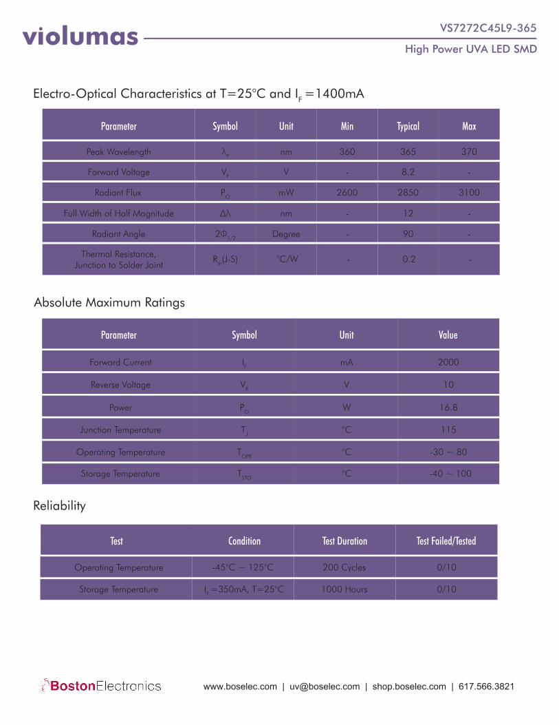
Electro-Optical Characteristics at T=25°C and IF =1400mA
Parameter Symbol Unit Min Typical Max
Peak Wavelength λP nm
VFForward Voltage
360 365 370
Radiant Flux
Full Width of Half Magnitude
Radiant Angle
Thermal Resistance, Junction to Solder Joint
PO
∆λ
2Φ1/2
Rth(J-S)
V - 8.2 -
mW 2600 2850 3100
nm - 12 -
Degree - 90 -
°C/W - 0.2 -
Parameter Symbol Unit Value
Absolute Maximum Ratings
Test Condition Test Duration Test Failed/Tested
Reliability
Forward Current
Reverse Voltage
Power
Junction Temperature
Operating Temperature
Storage Temperature
IF
VR
PO
TJ
TOPR
TSTG
mA
V
W
°C
°C
2000
10
16.8
115
-30 ~ 80
°C -40 ~ 100
Operating Temperature
Storage Temperature
-45°C ~ 125°C
IF =350mA, T=25°C
200 Cycles
1000 Hours
0/10
0/10
www.boselec.com | [email protected] | shop.boselec.com | 617.566.3821

High Power UVA LED SMDviolumas VS7272C45L9-365
Mechanical Dimensions
Radiation Pattern
Top View Side View Bottom View
7.20
7.20
Optical Reference
5.20
1.20
R3.00
1.80
7.20
5.22
0.35
0.35
7.20
1.40
3.10
1.40
Anode
Pillar
Cathode
www.boselec.com | [email protected] | shop.boselec.com | 617.566.3821
High Power UVA LED SMDviolumas VS7272C45L9-365
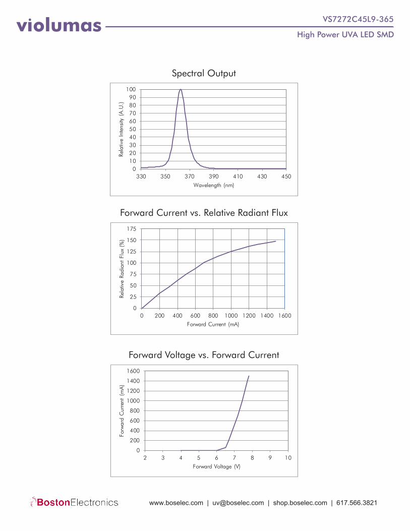
Forward Current vs. Relative Radiant Flux
Forward Voltage vs. Forward Current
Spectral Output
0102030405060708090
100
330 350 370 390 410 430 450
Rela
tive
Inte
nsity
(A
.U.)
Wavelength (nm)
0
25
50
75
100
125
150
175
0 200 400 600 800 1000 1200 1400 1600
Rela
tive
Radi
ant
Flux
(%
)
Forward Current (mA)
0
200
400
600
800
1000
1200
1400
1600
2 3 4 5 6 7 8 9 10
Forw
ard
Cur
rent
(m
A)
Forward Voltage (V)
www.boselec.com | [email protected] | shop.boselec.com | 617.566.3821
High Power UVA LED SMDviolumas VS7272C45L9-365
Handling & Usage Precautions• Exhibit extreme care when handling LEDs. Do not touch the LED with bare hands as doing so may contaminate and
affect the optical characteristics of the LED. When using tweezers, do not apply excessive force, especially to theglass lens. Do not drop the LED as doing so may cause product damage.
• Ensure that electrostatic discharge specifications are followed. Static electricity and surge voltages may causeproduct damage. Proper electrostatic discharge protection equipment, working machinery, and protected mountingequipment are recommended.
• Do not expose the LEDs to volatile organic compounds as well as hazardous, acidic, and corrosive substancesduring storage and operation to avoid product damage.
• Do not apply excess mechanical force and vibration while handling the product.• Do not expose the product to sudden changes in temperature, high humidity levels, and condensation.• Ensure that the PCB is suitable for the product and be wary of LED placement and possible PCB warpage.
Recommended MCPCBViolumas recommends the use of the Pillar MCPCB with Violumas LEDs for maximum performance and reliability. The data presented in this document is measured from the use of exclusive Flip Chip Opto patented products - the 3-PAD LED Flip Chip and the Pillar MCPCB. Please consult the Violumas engineering team for further recommendations on MCPCB options.
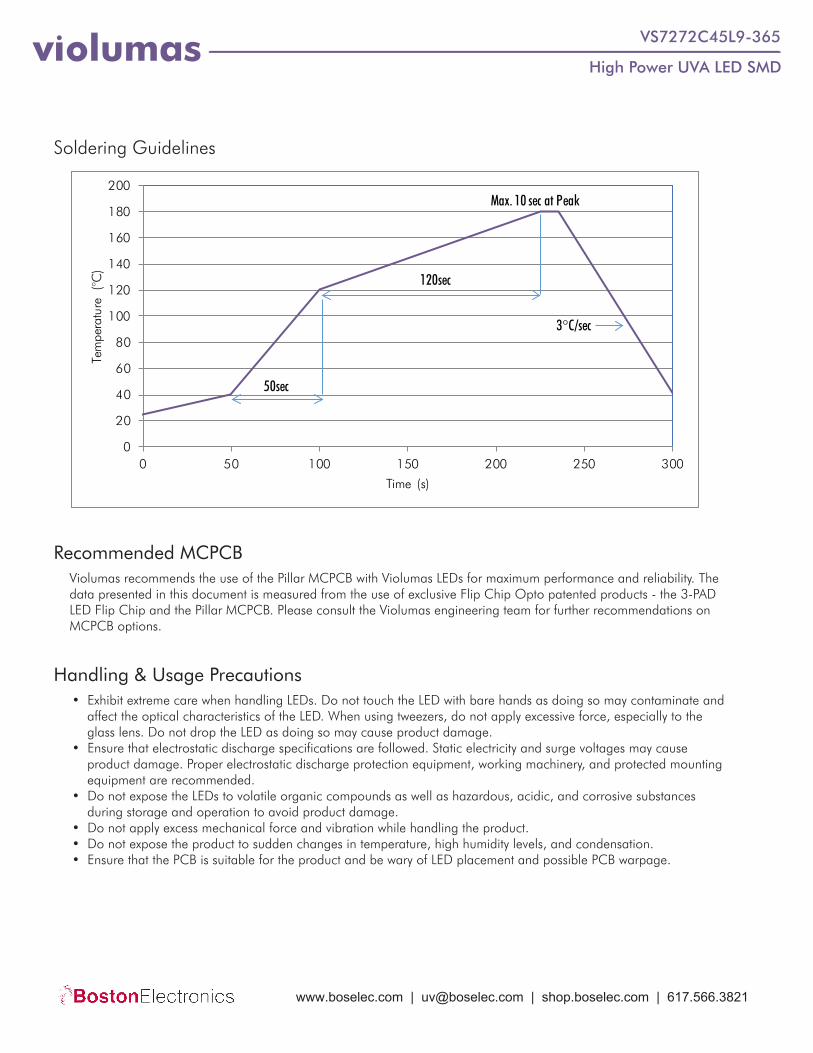
Soldering Guidelines
0
20
40
60
80
100
120
140
160
180
200
0 50 100 150 200 250 300
Tem
pera
ture
(°
C)
Time (s)
Max. 10 sec at Peak
3�C/sec
50sec
120sec
www.boselec.com | [email protected] | shop.boselec.com | 617.566.3821
High Power UVA LED SMDviolumas VS7272C45L9-365
Storage Precautions
Eye Safety Precautions
• Perform soldering as soon as the moisture-proof packaging is opened.• After the storage duration has exceeded the recommended time, products may need to be baked before soldering.• Store all products in a controlled environment under 30° C free of dust. Do not expose the product to sudden
changes in temperature, high humidity levels, and condensation.• Please consult the Violumas engineering team for further information on storage precautions.
• Avoid exposure to UV light during LED operation. Do not look directly into the UV light during LED operation. Donot look directly into the UV light during optical measurements even through optical instruments. Protect the body,skin, and eyes with UV protective equipment.
• Attach warning labels on all products and systems that use UV LEDs.
Cleaning Precautions• Do not use brushes or organic solvents for cleaning the LEDs.• Perform electrical and optical measurements before and after cleaning to ensure optimal performance.
Static Electricity Precautions• Ensure that equipment and machinery are properly grounded.• Anti-electrostatic attire (wristbands, gloves, footwear, etc.) is recommended.• Damage inspection is recommended while performing characteristics inspection of LEDs.
DisclaimersViolumas is not responsible for any damages that result from inaccurate use of the recommended guidelines. The information compiled in this document is a result of careful review of reference materials and reliable sources. Violumas does not make any claims regarding warranty or guarantee. It is recommended that each customer consults the Violumas engineering team before engaging Violumas products in extreme applications where the failure of the LED and damage to human health may be possible. Each user assumes full responsibility for determining the suitabil-ity of the use of Violumas products in various applications. Disassembling Violumas products without consent is prohibited. No part of these documents may be reproduced in any form without prior written permission from Violumas. Please note that the data presented in this document is measured from the use of exclusive Flip Chip Opto patented products - the 3-PAD LED Flip Chip and the Pillar MCPCB.
www.boselec.com | [email protected] | shop.boselec.com | 617.566.3821
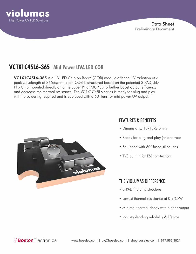
VC1X1C45L6-365 Mid Power UVA LED COB
VC1X1C45L6-365 is a UV LED Chip on Board (COB) module offering UV radiation at a peak wavelength of 365±5nm. Each COB is structured based on the patented 3-PAD LED Flip Chip mounted directly onto the Super Pillar MCPCB to further boost output efficiency and decrease the thermal resistance. The VC1X1C45L6 series is ready for plug and play with no soldering required and is equipped with a 60° lens for mid power UV output.
• Dimensions: 15x15x3.0mm
• Ready for plug and play (solder-free)
• Equipped with 60° fused silica lens
• TVS built in for ESD protection
FEATURES & BENEFITS
• 3-PAD flip chip structure
• Lowest thermal resistance at 0.9°C/W
• Minimal thermal decay with higher output
• Industry-leading reliability & lifetime
THE VIOLUMAS DIFFERENCE
Data Sheet
violumasHigh Power UV LED Solutions
Preliminary Document
www.boselec.com | [email protected] | shop.boselec.com | 617.566.3821

Mid Power UVA LED COBviolumas VC1X1C45L6-365
Electro-Optical Characteristics at T=25°C and IF =700mA
Parameter Symbol Unit Min Typical Max
Peak Wavelength λP nm
VFForward Voltage
360 365 370
Radiant Flux
Full Width of Half Magnitude
Radiant Angle
Thermal Resistance, Junction to Solder Joint
PO
∆λ
2Φ1/2
Rth(J-S)
V - 4.1 -
mW 750 775 800
nm - 12 -
Degree - 60 -
°C/W - 0.9 -
Parameter Symbol Unit Value
Absolute Maximum Ratings
Test Condition Test Duration Test Failed/Tested
Reliability
Forward Current
Reverse Voltage
Power
Junction Temperature
Operating Temperature
Storage Temperature
IF
VR
PO
TJ
TOPR
TSTG
mA
V
W
°C
°C
1000
5
4
115
-30 ~ 80
°C -40 ~ 100
Operating Temperature
Storage Temperature
-45°C ~ 125°C
IF =350mA, T=25°C
200 Cycles
1000 Hours
0/10
0/10
www.boselec.com | [email protected] | shop.boselec.com | 617.566.3821
Mid Power UVA LED COBviolumas VC1X1C45L6-365
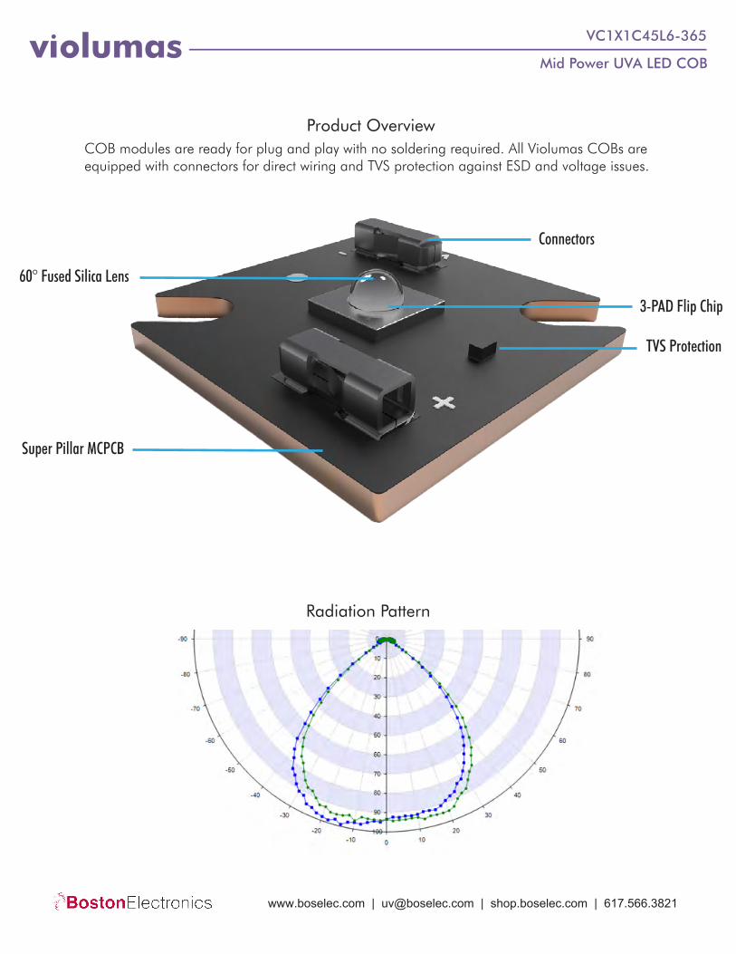
Product Overview
Radiation Pattern
TVS Protection
COB modules are ready for plug and play with no soldering required. All Violumas COBs are equipped with connectors for direct wiring and TVS protection against ESD and voltage issues.
60° Fused Silica Lens
Connectors
Super Pillar MCPCB
3-PAD Flip Chip
www.boselec.com | [email protected] | shop.boselec.com | 617.566.3821
Mid Power UVA LED COBviolumas VC1X1C45L6-365
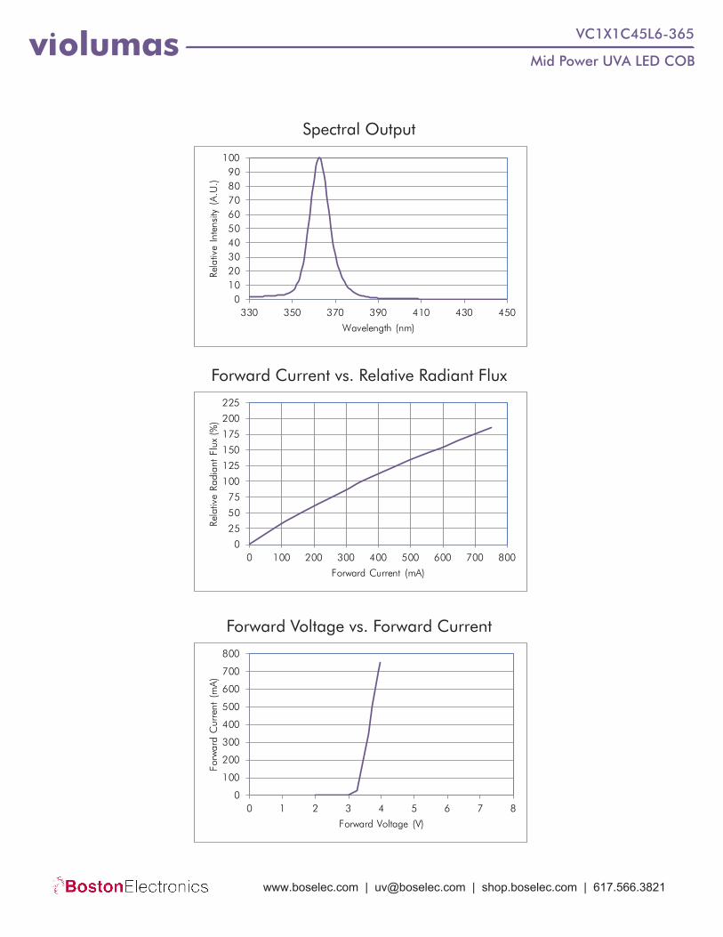
Forward Current vs. Relative Radiant Flux
Forward Voltage vs. Forward Current
Spectral Output
0102030405060708090
100
330 350 370 390 410 430 450
Rela
tive
Inte
nsity
(A
.U.)
Wavelength (nm)
0
25
50
75
100
125
150
175
200
225
0 100 200 300 400 500 600 700 800
Rela
tive
Radi
ant
Flux
(%
)
Forward Current (mA)
0
100
200
300
400
500
600
700
800
0 1 2 3 4 5 6 7 8
Forw
ard
Cur
rent
(m
A)
Forward Voltage (V)
www.boselec.com | [email protected] | shop.boselec.com | 617.566.3821
Mid Power UVA LED COBviolumas VC1X1C45L6-365
Handling & Usage Precautions• Exhibit extreme care when handling LEDs. Do not touch the LED with bare hands as doing so may contaminate and
affect the optical characteristics of the LED. When using tweezers, do not apply excessive force, especially to theglass lens. Do not drop the LED as doing so may cause product damage.
• Ensure that electrostatic discharge specifications are followed. Static electricity and surge voltages may causeproduct damage. Proper electrostatic discharge protection equipment, working machinery, and protected mountingequipment are recommended.
• Do not expose the LEDs to volatile organic compounds as well as hazardous, acidic, and corrosive substancesduring storage and operation to avoid product damage.
• Do not apply excess mechanical force and vibration while handling the product.• Do not expose the product to sudden changes in temperature, high humidity levels, and condensation.• Ensure that the PCB is suitable for the product and be wary of LED placement and possible PCB warpage.
Storage Precautions
Eye Safety Precautions
• Perform soldering as soon as the moisture-proof packaging is opened.• After the storage duration has exceeded the recommended time, products may need to be baked before soldering.• Store all products in a controlled environment under 30° C free of dust. Do not expose the product to sudden
changes in temperature, high humidity levels, and condensation.• Please consult the Violumas engineering team for further information on storage precautions.
• Avoid exposure to UV light during LED operation. Do not look directly into the UV light during LED operation. Donot look directly into the UV light during optical measurements even through optical instruments. Protect the body,skin, and eyes with UV protective equipment.
• Attach warning labels on all products and systems that use UV LEDs.
Cleaning Precautions• Do not use brushes or organic solvents for cleaning the LEDs.• Perform electrical and optical measurements before and after cleaning to ensure optimal performance.
Static Electricity Precautions• Ensure that equipment and machinery are properly grounded.• Anti-electrostatic attire (wristbands, gloves, footwear, etc.) is recommended.• Damage inspection is recommended while performing characteristics inspection of LEDs.
DisclaimersViolumas is not responsible for any damages that result from inaccurate use of the recommended guidelines. The information compiled in this document is a result of careful review of reference materials and reliable sources. Violumas does not make any claims regarding warranty or guarantee. It is recommended that each customer consults the Violumas engineering team before engaging Violumas products in extreme applications where the failure of the LED and damage to human health may be possible. Each user assumes full responsibility for determining the suitabil-ity of the use of Violumas products in various applications. Disassembling Violumas products without consent is prohibited. No part of these documents may be reproduced in any form without prior written permission from Violumas. Please note that the data presented in this document is measured from the use of exclusive Flip Chip Opto patented products - the 3-PAD LED Flip Chip and the Pillar MCPCB.
www.boselec.com | [email protected] | shop.boselec.com | 617.566.3821
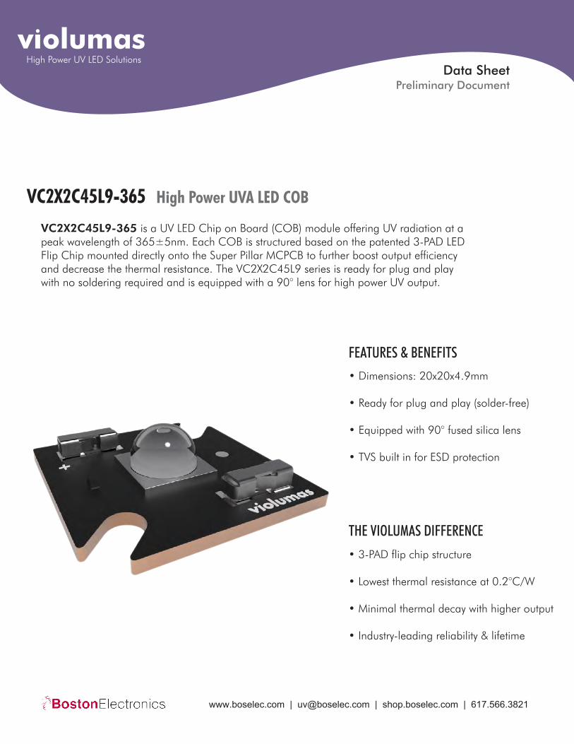
VC2X2C45L9-365 High Power UVA LED COB
VC2X2C45L9-365 is a UV LED Chip on Board (COB) module offering UV radiation at a peak wavelength of 365±5nm. Each COB is structured based on the patented 3-PAD LED Flip Chip mounted directly onto the Super Pillar MCPCB to further boost output efficiency and decrease the thermal resistance. The VC2X2C45L9 series is ready for plug and play with no soldering required and is equipped with a 90° lens for high power UV output.
• Dimensions: 20x20x4.9mm
• Ready for plug and play (solder-free)
• Equipped with 90° fused silica lens
• TVS built in for ESD protection
FEATURES & BENEFITS
• 3-PAD flip chip structure
• Lowest thermal resistance at 0.2°C/W
• Minimal thermal decay with higher output
• Industry-leading reliability & lifetime
THE VIOLUMAS DIFFERENCE
Data Sheet
violumasHigh Power UV LED Solutions
Preliminary Document
www.boselec.com | [email protected] | shop.boselec.com | 617.566.3821
High Power UVA LED COBviolumas VC2X2C45L9-365
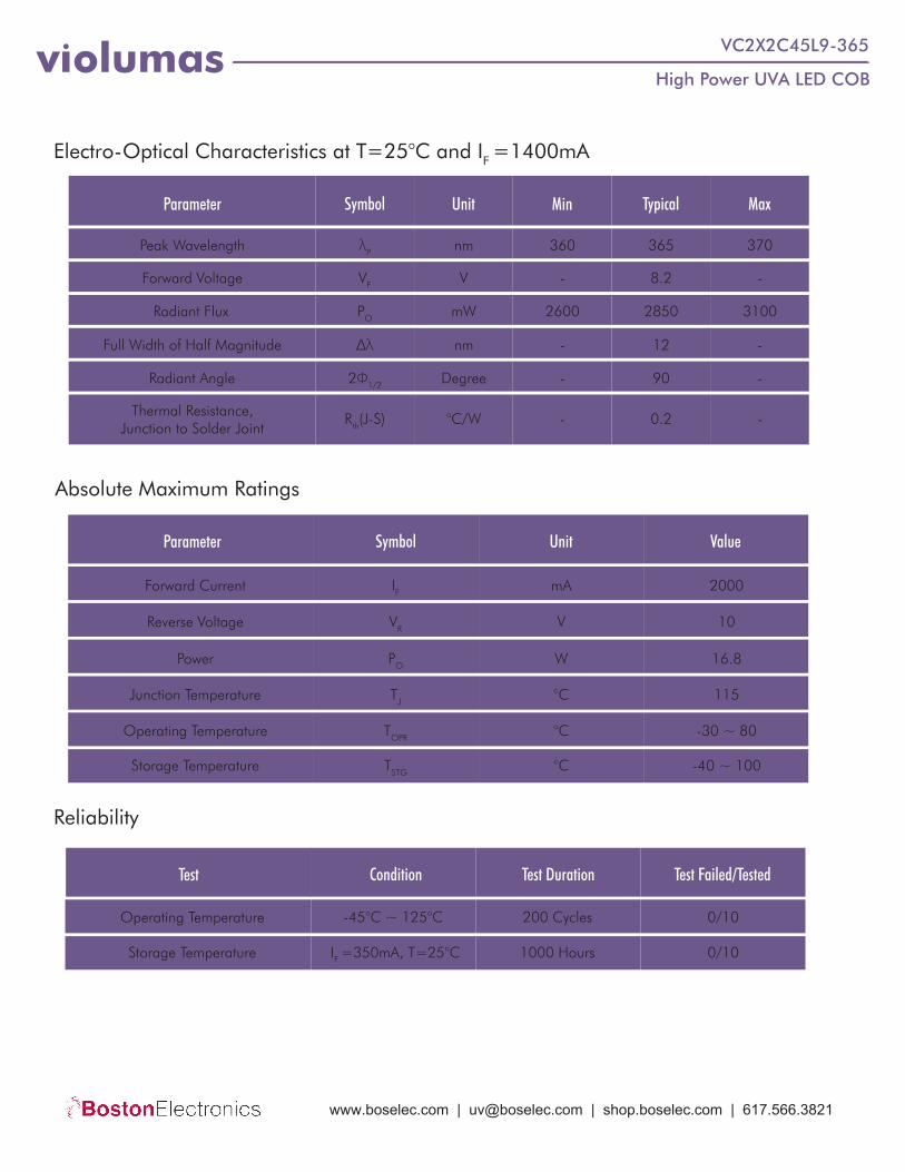
Electro-Optical Characteristics at T=25°C and IF =1400mA
Parameter Symbol Unit Min Typical Max
Peak Wavelength λP nm
VFForward Voltage
360 365 370
Radiant Flux
Full Width of Half Magnitude
Radiant Angle
Thermal Resistance, Junction to Solder Joint
PO
∆λ
2Φ1/2
Rth(J-S)
V - 8.2 -
mW 2600 2850 3100
nm - 12 -
Degree - 90 -
°C/W - 0.2 -
Parameter Symbol Unit Value
Absolute Maximum Ratings
Test Condition Test Duration Test Failed/Tested
Reliability
Forward Current
Reverse Voltage
Power
Junction Temperature
Operating Temperature
Storage Temperature
IF
VR
PO
TJ
TOPR
TSTG
mA
V
W
°C
°C
2000
10
16.8
115
-30 ~ 80
°C -40 ~ 100
Operating Temperature
Storage Temperature
-45°C ~ 125°C
IF =350mA, T=25°C
200 Cycles
1000 Hours
0/10
0/10
www.boselec.com | [email protected] | shop.boselec.com | 617.566.3821

High Power UVA LED COBviolumas VC2X2C45L9-365
Product Overview
Radiation Pattern
TVS Protection
COB modules are ready for plug and play with no soldering required. All Violumas COBs are equipped with connectors for direct wiring and TVS protection against ESD and voltage issues.
90° Fused Silica Lens
Connectors
Super Pillar MCPCB
3-PAD Flip Chip
www.boselec.com | [email protected] | shop.boselec.com | 617.566.3821
High Power UVA LED COBviolumas VC2X2C45L9-365
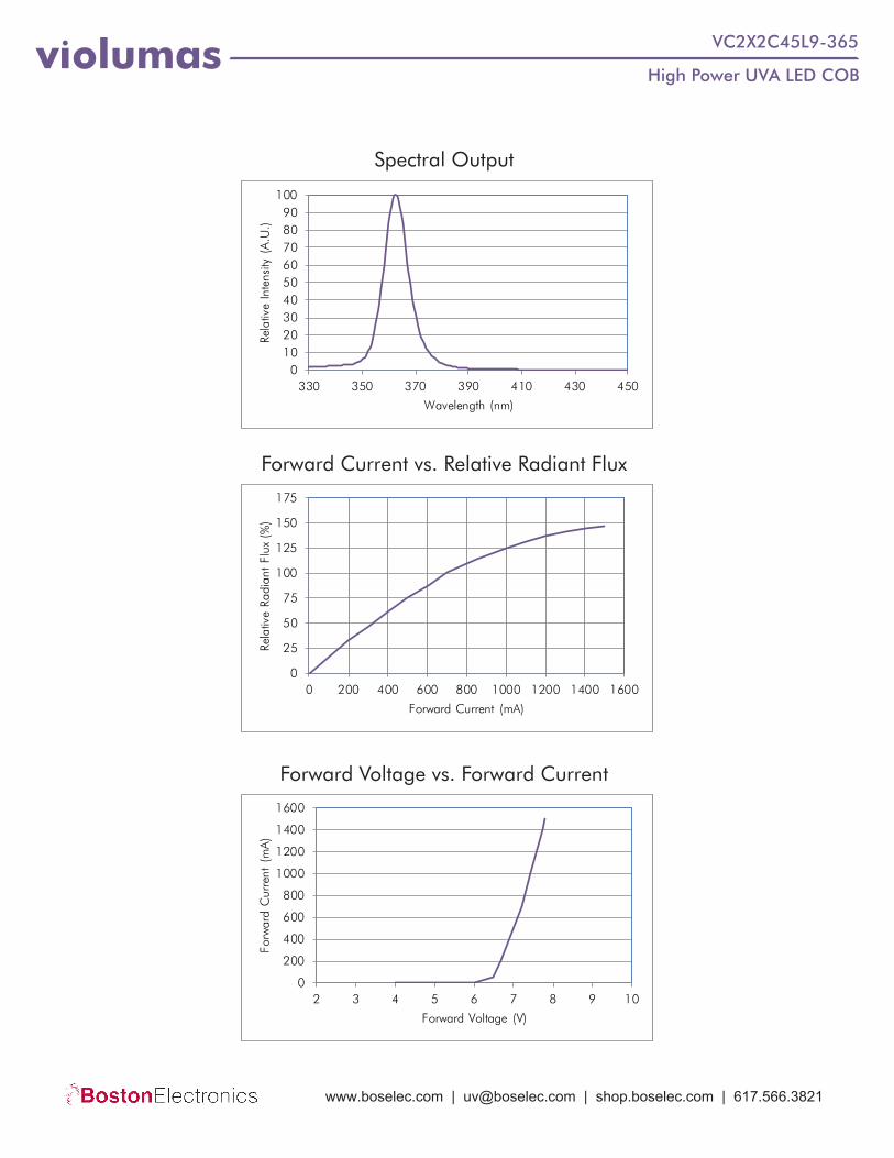
Forward Current vs. Relative Radiant Flux
Forward Voltage vs. Forward Current
Spectral Output
0102030405060708090
100
330 350 370 390 410 430 450
Rela
tive
Inte
nsity
(A
.U.)
Wavelength (nm)
0
25
50
75
100
125
150
175
0 200 400 600 800 1000 1200 1400 1600
Rela
tive
Radi
ant
Flux
(%
)
Forward Current (mA)
0
200
400
600
800
1000
1200
1400
1600
2 3 4 5 6 7 8 9 10
Forw
ard
Cur
rent
(m
A)
Forward Voltage (V)
www.boselec.com | [email protected] | shop.boselec.com | 617.566.3821

High Power UVA LED COBviolumas VC2X2C45L9-365
Handling & Usage Precautions• Exhibit extreme care when handling LEDs. Do not touch the LED with bare hands as doing so may contaminate and
affect the optical characteristics of the LED. When using tweezers, do not apply excessive force, especially to theglass lens. Do not drop the LED as doing so may cause product damage.
• Ensure that electrostatic discharge specifications are followed. Static electricity and surge voltages may causeproduct damage. Proper electrostatic discharge protection equipment, working machinery, and protected mountingequipment are recommended.
• Do not expose the LEDs to volatile organic compounds as well as hazardous, acidic, and corrosive substancesduring storage and operation to avoid product damage.
• Do not apply excess mechanical force and vibration while handling the product.• Do not expose the product to sudden changes in temperature, high humidity levels, and condensation.• Ensure that the PCB is suitable for the product and be wary of LED placement and possible PCB warpage.
Storage Precautions
Eye Safety Precautions
• Perform soldering as soon as the moisture-proof packaging is opened.• After the storage duration has exceeded the recommended time, products may need to be baked before soldering.• Store all products in a controlled environment under 30° C free of dust. Do not expose the product to sudden
changes in temperature, high humidity levels, and condensation.• Please consult the Violumas engineering team for further information on storage precautions.
• Avoid exposure to UV light during LED operation. Do not look directly into the UV light during LED operation. Donot look directly into the UV light during optical measurements even through optical instruments. Protect the body,skin, and eyes with UV protective equipment.
• Attach warning labels on all products and systems that use UV LEDs.
Cleaning Precautions• Do not use brushes or organic solvents for cleaning the LEDs.• Perform electrical and optical measurements before and after cleaning to ensure optimal performance.
Static Electricity Precautions• Ensure that equipment and machinery are properly grounded.• Anti-electrostatic attire (wristbands, gloves, footwear, etc.) is recommended.• Damage inspection is recommended while performing characteristics inspection of LEDs.
DisclaimersViolumas is not responsible for any damages that result from inaccurate use of the recommended guidelines. The information compiled in this document is a result of careful review of reference materials and reliable sources. Violumas does not make any claims regarding warranty or guarantee. It is recommended that each customer consults the Violumas engineering team before engaging Violumas products in extreme applications where the failure of the LED and damage to human health may be possible. Each user assumes full responsibility for determining the suitabil-ity of the use of Violumas products in various applications. Disassembling Violumas products without consent is prohibited. No part of these documents may be reproduced in any form without prior written permission from Violumas. Please note that the data presented in this document is measured from the use of exclusive Flip Chip Opto patented products - the 3-PAD LED Flip Chip and the Pillar MCPCB.
www.boselec.com | [email protected] | shop.boselec.com | 617.566.3821
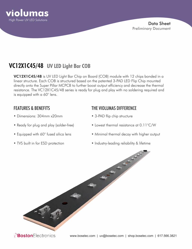
VC12X1C45/48 UV LED Light Bar COB
VC12X1C45/48 is UV LED Light Bar Chip on Board (COB) module with 12 chips bonded in a linear structure. Each COB is structured based on the patented 3-PAD LED Flip Chip mounted directly onto the Super Pillar MCPCB to further boost output efficiency and decrease the thermal resistance. The VC12X1C45/48 series is ready for plug and play with no soldering required and is equipped with a 60° lens.
• Dimensions: 304mm x20mm
• Ready for plug and play (solder-free)
• Equipped with 60° fused silica lens
• TVS built in for ESD protection
FEATURES & BENEFITS• 3-PAD flip chip structure
• Lowest thermal resistance at 0.11°C/W
• Minimal thermal decay with higher output
• Industry-leading reliability & lifetime
THE VIOLUMAS DIFFERENCE
Data Sheet
violumasHigh Power UV LED Solutions
Preliminary Document
www.boselec.com | [email protected] | shop.boselec.com | 617.566.3821
UV LED Light Bar COBviolumas VC12X1C45/48
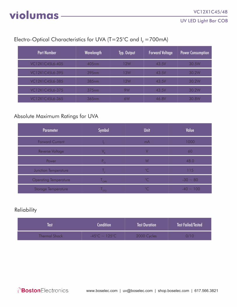
Electro-Optical Characteristics for UVA (T=25°C and IF =700mA)
Parameter Symbol Unit Value
Absolute Maximum Ratings for UVA
Forward Current
Reverse Voltage
Power
Junction Temperature
Operating Temperature
Storage Temperature
IF
VR
PO
TJ
TOPR
TSTG
mA
V
W
°C
°C
1000
60
48.0
115
-30 ~ 80
°C -40 ~ 100
Part Number Wavelength Typ. Output Forward Voltage Power Consumption
VC12X1C45L6-405
VC12X1C45L6-395
VC12X1C45L6-385
VC12X1C45L6-375
VC12X1C45L6-365
405nm
395nm
385nm
375nm
365nm
12W
13W
12W
9W
6W
43.5V
43.5V
43.5V
43.5V
46.8V
30.5W
30.2W
30.2W
30.2W
30.8W
Test Condition Test Duration Test Failed/Tested
Reliability
Thermal Shock -45°C ~ 125°C 2000 Cycles 0/10
www.boselec.com | [email protected] | shop.boselec.com | 617.566.3821
UV LED Light Bar COBviolumas VC12X1C45/48
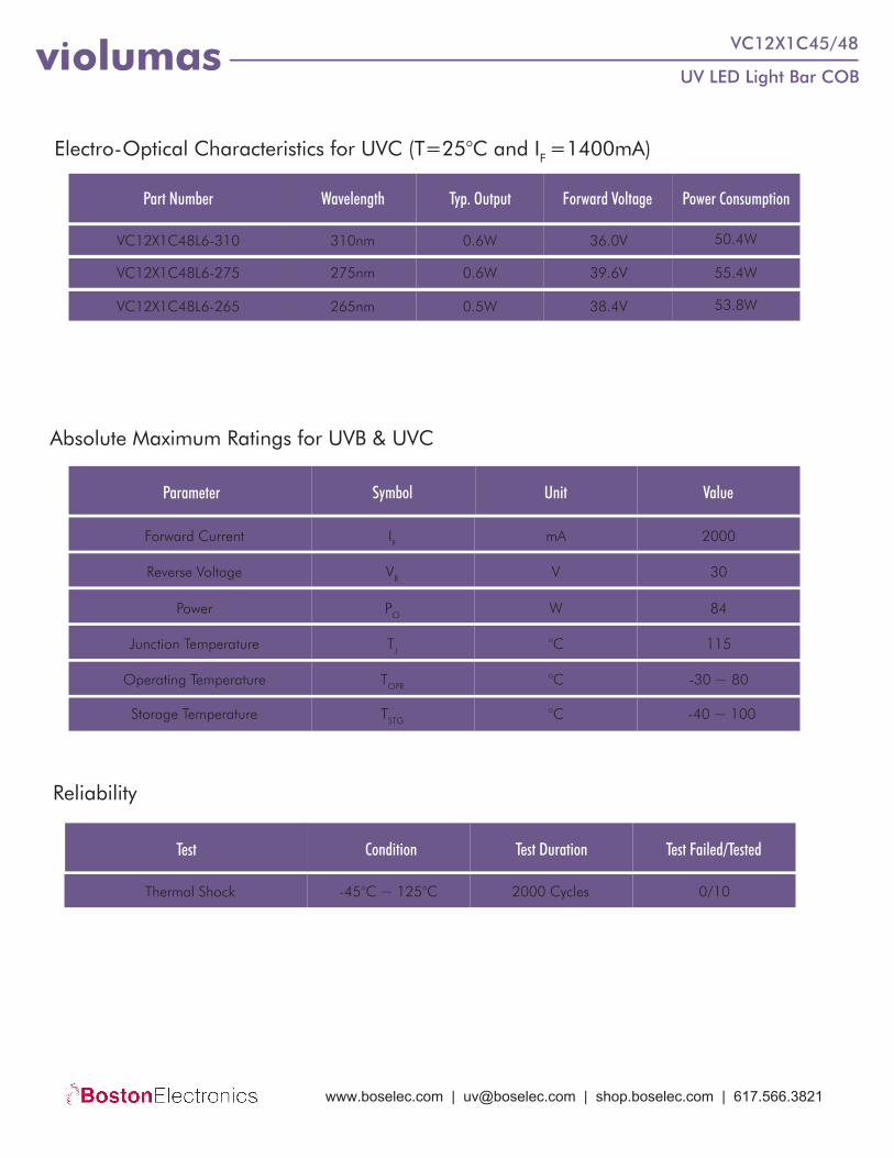
Test Condition Test Duration Test Failed/Tested
Reliability
Thermal Shock -45°C ~ 125°C 2000 Cycles 0/10
Electro-Optical Characteristics for UVC (T=25°C and IF =1400mA)
Part Number Wavelength Typ. Output Forward Voltage Power Consumption
VC12X1C48L6-310
VC12X1C48L6-275
VC12X1C48L6-265
310nm
275nm
265nm
0.6W
0.6W
0.5W
36.0V
39.6V
38.4V
50.4W
55.4W
53.8W
Parameter Symbol Unit Value
Absolute Maximum Ratings for UVB & UVC
Forward Current
Reverse Voltage
Power
Junction Temperature
Operating Temperature
Storage Temperature
IF
VR
PO
TJ
TOPR
TSTG
mA
V
W
°C
°C
2000
30
84
115
-30 ~ 80
°C -40 ~ 100
www.boselec.com | [email protected] | shop.boselec.com | 617.566.3821

Product Overview
UV LED Light Bar COBviolumas VC12X1C45/48
TVS Protection
COB modules are ready for plug and play with no soldering required. All Violumas COBs are equipped with connectors for direct wiring and TVS protection against ESD and voltage issues.
60° Fused Silica Lens
Connectors
Super Pillar MCPCB3-PAD Flip Chip
300 350 400 450 500 550 600 650
50
45
40
35
30
25
2P Light Bar
3P Light Bar
2P vs 3P Light Bar Intensity Comparison
When driving at higher currents for extended periods of time, Violumas 3-PAD chips exhibit less thermal decay, allowing for more UV intensity than conven-tional chips at the same driving current.
The specialized chip architecture works with the Pillar MCPCB to redirect the heat away module, minimizing the need for large heat sinks
Irrad
ianc
e In
tens
ity (m
W/c
m2)
Input Current (mA)
www.boselec.com | [email protected] | shop.boselec.com | 617.566.3821

UV LED Light Bar COBviolumas VC12X1C45/48
Handling & Usage Precautions• Exhibit extreme care when handling LEDs. Do not touch the LED with bare hands as doing so may contaminate and
affect the optical characteristics of the LED. When using tweezers, do not apply excessive force, especially to theglass lens. Do not drop the LED as doing so may cause product damage.
• Ensure that electrostatic discharge specifications are followed. Static electricity and surge voltages may causeproduct damage. Proper electrostatic discharge protection equipment, working machinery, and protected mountingequipment are recommended.
• Do not expose the LEDs to volatile organic compounds as well as hazardous, acidic, and corrosive substancesduring storage and operation to avoid product damage.
• Do not apply excess mechanical force and vibration while handling the product.• Do not expose the product to sudden changes in temperature, high humidity levels, and condensation.• Ensure that the PCB is suitable for the product and be wary of LED placement and possible PCB warpage.
Storage Precautions
Eye Safety Precautions
• Perform soldering as soon as the moisture-proof packaging is opened.• After the storage duration has exceeded the recommended time, products may need to be baked before soldering.• Store all products in a controlled environment under 30° C free of dust. Do not expose the product to sudden
changes in temperature, high humidity levels, and condensation.• Please consult the Violumas engineering team for further information on storage precautions.
• Avoid exposure to UV light during LED operation. Do not look directly into the UV light during LED operation. Donot look directly into the UV light during optical measurements even through optical instruments. Protect the body,skin, and eyes with UV protective equipment.
• Attach warning labels on all products and systems that use UV LEDs.
Cleaning Precautions• Do not use brushes or organic solvents for cleaning the LEDs.• Perform electrical and optical measurements before and after cleaning to ensure optimal performance.
Static Electricity Precautions• Ensure that equipment and machinery are properly grounded.• Anti-electrostatic attire (wristbands, gloves, footwear, etc.) is recommended.• Damage inspection is recommended while performing characteristics inspection of LEDs.
DisclaimersViolumas is not responsible for any damages that result from inaccurate use of the recommended guidelines. The information compiled in this document is a result of careful review of reference materials and reliable sources. Violumas does not make any claims regarding warranty or guarantee. It is recommended that each customer consults the Violumas engineering team before engaging Violumas products in extreme applications where the failure of the LED and damage to human health may be possible. Each user assumes full responsibility for determining the suitabil-ity of the use of Violumas products in various applications. Disassembling Violumas products without consent is prohibited. No part of these documents may be reproduced in any form without prior written permission from Violumas. Please note that the data presented in this document is measured from the use of exclusive Flip Chip Opto patented products - the 3-PAD LED Flip Chip and the Pillar MCPCB.
www.boselec.com | [email protected] | shop.boselec.com | 617.566.3821
[email protected] | www.boselec.com | 617-566-3821
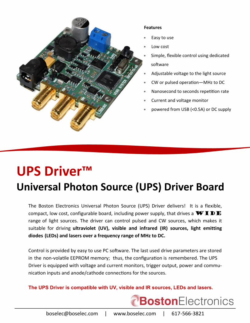
UPS Driver™ Universal Photon Source (UPS) Driver Board
Features
Easy to use
Low cost
Simple, flexible control using dedicated
software
Adjustable voltage to the light source
CW or pulsed operation—MHz to DC
Nanosecond to seconds repetition rate
Current and voltage monitor
powered from USB (<0.5A) or DC supply
The Boston Electronics Universal Photon Source (UPS) Driver delivers! It is a flexible,
compact, low cost, configurable board, including power supply, that drives a widerange of light sources. The driver can control pulsed and CW sources, which makes it
suitable for driving ultraviolet (UV), visible and infrared (IR) sources, light emitting
diodes (LEDs) and lasers over a frequency range of MHz to DC.
Control is provided by easy to use PC software. The last used drive parameters are stored
in the non-volatile EEPROM memory; thus, the configuration is remembered. The UPS
Driver is equipped with voltage and current monitors, trigger output, power and commu-
nication inputs and anode/cathode connections for the sources.
The UPS Driver is compatible with UV, visible and IR sources, LEDs and lasers.
[email protected] | www.boselec.com | 617-566-3821
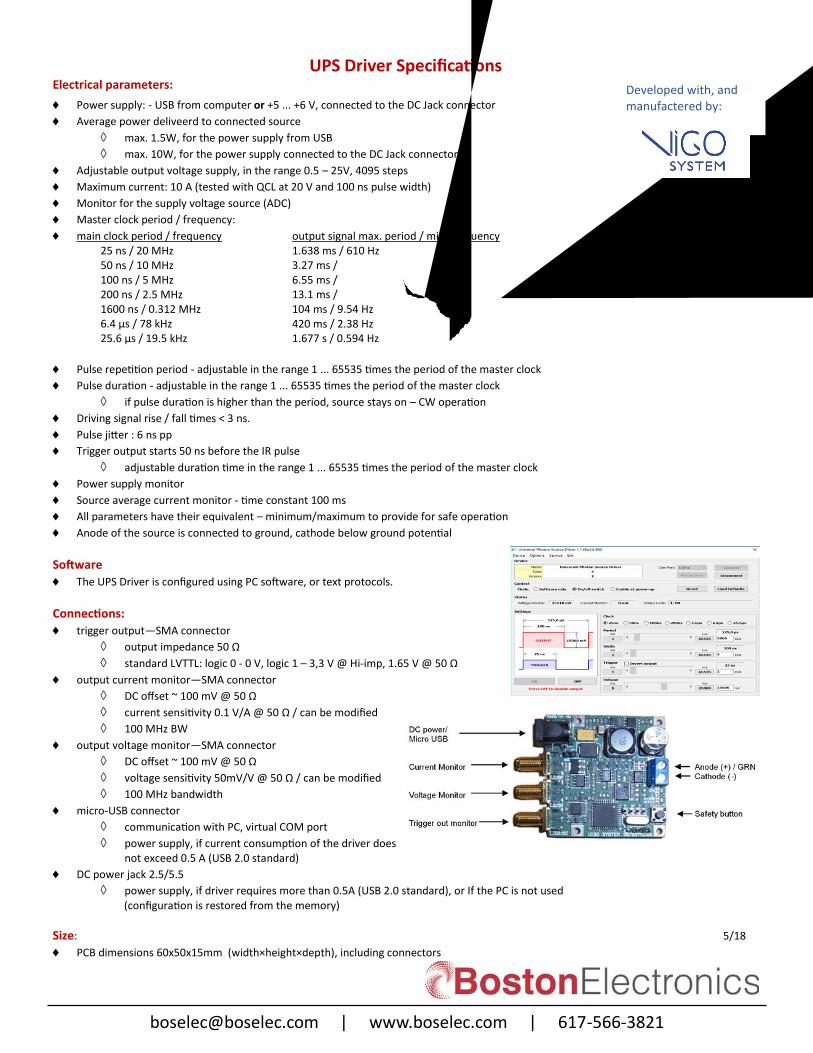
UPS Driver Specifications Electrical parameters:
Power supply: - USB from computer or +5 ... +6 V, connected to the DC Jack connector
Average power deliveerd to connected source
max. 1.5W, for the power supply from USB
max. 10W, for the power supply connected to the DC Jack connector
Adjustable output voltage supply, in the range 0.5 – 25V, 4095 steps
Maximum current: 10 A (tested with QCL at 20 V and 100 ns pulse width)
Monitor for the supply voltage source (ADC)
Master clock period / frequency:
main clock period / frequency output signal max. period / min. frequency 1.638 ms / 610 Hz 3.27 ms / 305 Hz 6.55 ms / 152 Hz 13.1 ms / 76.3 Hz 104 ms / 9.54 Hz 420 ms / 2.38 Hz
25 ns / 20 MHz50 ns / 10 MHz100 ns / 5 MHz200 ns / 2.5 MHz1600 ns / 0.312 MHz6.4 μs / 78 kHz 25.6 μs / 19.5 kHz 1.677 s / 0.594 Hz
Pulse repetition period - adjustable in the range 1 ... 65535 times the period of the master clock
Pulse duration - adjustable in the range 1 ... 65535 times the period of the master clock
if pulse duration is higher than the period, source stays on – CW operation
Driving signal rise / fall times < 3 ns.
Pulse jitter : 6 ns pp
Trigger output starts 50 ns before the IR pulse
adjustable duration time in the range 1 ... 65535 times the period of the master clock
Power supply monitor
Source average current monitor - time constant 100 ms
All parameters have their equivalent – minimum/maximum to provide for safe operation
Anode of the source is connected to ground, cathode below ground potential
Software
The UPS Driver is configured using PC software, or text protocols.
Connections: trigger output—SMA connector
output impedance 50 Ω
standard LVTTL: logic 0 - 0 V, logic 1 – 3,3 V @ Hi-imp, 1.65 V @ 50 Ω
output current monitor—SMA connector
DC offset ~ 100 mV @ 50 Ω
current sensitivity 0.1 V/A @ 50 Ω / can be modified
100 MHz BW
output voltage monitor—SMA connector
DC offset ~ 100 mV @ 50 Ω
voltage sensitivity 50mV/V @ 50 Ω / can be modified
100 MHz bandwidth
micro-USB connector
communication with PC, virtual COM port
power supply, if current consumption of the driver does not exceed 0.5 A (USB 2.0 standard)
DC power jack 2.5/5.5
power supply, if driver requires more than 0.5A (USB 2.0 standard), or If the PC is not used (configuration is restored from the memory)
Size: 5/18 PCB dimensions 60x50x15mm (width×height×depth), including connectors
Developed with, and manufactered by: