3500/25 enhanced keyphasor module - wordpress.com · 6.1 self-test ... 6.4 alarm event list...
TRANSCRIPT

Bently Nevada™ Asset Condition Monitoring Operation and Maintenance Manual
3500/25 Enhanced Keyphasor® Module
Part Number 129770-01 Rev. N (03/08)

3500/25 Enhanced Keyphasor Module Operation and Maintenance Manual
Copyright 1995. Bently Nevada LLC.
All rights reserved.
The information contained in this document is subject to change without notice. The following are trademarks of General Electric Company in the United States and other countries: Bently Nevada, Keyphasor, and Proximitor The following are trademarks of the legal entities cited: 3M and Velostat are trademarks of 3M Company.
Contact Information The following contact information is provided for those times when you cannot contact your local representative:
Mailing Address 1631 Bently Parkway South Minden, Nevada USA 89423 USA
Telephone 1.775.782.3611 1.800.227.5514
Fax 1.775.215.2873 Internet www.ge-energy.com/bently
ii

Additional Information
Notice: This manual does not contain all the information required to operate and maintain the product. Refer to the following manuals for other required information. 3500 Monitoring System Rack Installation and Maintenance Manual (129766-01)
• general description of a standard system • general description of a Triple Modular redundant (TMR) system • instructions for installing and removing the module from a 3500 Rack
3500 Monitoring System Rack Configuration and Utilities Guide (129777-01)
• guidelines for using the 3500 Rack Configuration software for setting the operating parameters of the module
• guidelines for using the 3500 test utilities to verify that the input and output terminals on the module are operating properly
3500 Monitoring System Computer Hardware and Software Manual (128158-01)
• instructions for connecting the rack to 3500 host computer • procedures for verifying communication • procedures for installing software • guidelines for using Data Acquisition / DDE Server and Operator Display Software • procedures and diagrams for setting up network and remote communications
3500 Field Wiring Diagram Package (130432-01) • diagrams that show how to hook up a particular transducer
• lists of recommended wiring
Product Disposal Statement Customers and third parties, who are not member states of the European Union, who are in control of the product at the end of its life or at the end of its use, are solely responsible for the proper disposal of the product. No person, firm, corporation, association or agency that is in control of product shall dispose of it in a manner that is in violation of any applicable federal, state, local or international law. Bently Nevada LLC is not responsible for the disposal of the product at the end of its life or at the end of its use.
iii

3500/25 Enhanced Keyphasor Module Operation and Maintenance Manual
Contents
1. Receiving and Handling Instructions..........................................................1 1.1 Receiving Inspection........................................................................................................................ 1 1.2 Handling and Storage Considerations .................................................................................... 1
2. General Information ......................................................................................3 2.1 Module Compatibility....................................................................................................................... 4 2.2 Expanded Signal Processing Capability .................................................................................. 4 2.3 Paired Keyphasor Signal Capability .......................................................................................... 5
2.3.1 Overview........................................................................................................................................... 5 2.3.2 Conditions for Selecting the Output Signal....................................................................... 6 2.3.3 Special Considerations .............................................................................................................. 7
2.4 Triple Modular Redundant (TMR) Description ....................................................................... 7 2.5 Available Data..................................................................................................................................... 8
2.5.1 Module Statuses ........................................................................................................................... 8 2.5.2 Channel Status .............................................................................................................................. 9
2.6 LED Descriptions..............................................................................................................................10
3. Configuration Information..........................................................................11 3.1 Hardware Considerations ...........................................................................................................11
3.1.1 General............................................................................................................................................11 3.1.2 Paired Keyphasor Signal Hardware Restrictions .........................................................11
3.2 Software Configuration Considerations................................................................................12 3.2.1 Keyphasor Module/3500 Monitor Configuration Interaction .................................12 3.2.2 Signal Paths and Signal Options..........................................................................................12 3.2.3 Event Setup Options..................................................................................................................13 3.2.4 Keyphasor Signal Rate Division by 3500 Monitors......................................................13 3.2.5 Restriction On Availability of Absolute Phase Information ......................................14 3.2.6 Phase Accuracy Limitation of Processed Signals ........................................................14 3.2.7 Limitations When Specifying an Events Ratio Setup..................................................15
3.3 Software Configuration Options...............................................................................................17 3.3.1 Keyphasor Module Configuration Options......................................................................17 3.3.2 Keyphasor Module Configuration Screen Examples..................................................24 3.3.3 Paired Keyphasor Signal Configuration ...........................................................................28 3.3.4 Paired Keyphasor Signal Configuration Screen Examples ......................................29 3.3.5 Software Switches .....................................................................................................................30 3.3.6 Software Switch Options.........................................................................................................31
iv

4. Keyphasor I/O Module Descriptions ........................................................ 33 4.1 Internal Termination Keyphasor I/O Modules ....................................................................34
4.1.1 Non-Isolated Internal Termination Keyphasor I/O Module .....................................34 4.1.2 Isolated Internal Termination Keyphasor I/O Module................................................35 4.1.3 Internal Barrier Internal Termination Keyphasor I/O Module.................................36 4.1.4 Euro Style Connectors..............................................................................................................36
4.2 External Termination Keyphasor I/O Modules ...................................................................37 4.2.1 Non-Isolated External Termination Keyphasor I/O Module ....................................38 4.2.2 Isolated External Termination Keyphasor I/O Module...............................................38 4.2.3 External Termination Blocks..................................................................................................40 4.2.4 External Termination Block Cable Signal Pinouts ........................................................41
5. Maintenance................................................................................................. 43 5.1 Verifying Keyphasor Module Operation ................................................................................43
5.1.1 Choosing a Maintenance Interval.......................................................................................43 5.1.2 Required Verification Test Equipment...............................................................................43 5.1.3 Typical Verification Test Setup .............................................................................................44 5.1.4 Using 3500 Rack Configuration Software For Verification Testing......................45 5.1.5 Procedure For Verifying Keyphasor Module Channels..............................................46 5.1.6 If a Channel Fails a Verification Test..................................................................................51
5.2 Replacing or Upgrading Firmware ..........................................................................................51 5.2.1 Determine The Firmware Replacement Process To Use ..........................................52 5.2.2 Replace the Firmware IC.........................................................................................................52 5.2.3 Firmware Download Via Rack Configuration Software ............................................56
6. Troubleshooting........................................................................................... 59 6.1 Self-Test ...............................................................................................................................................59 6.2 LED States...........................................................................................................................................59 6.3 System Event List Messages ......................................................................................................60
6.3.1 List of System Event Messages ............................................................................................61 6.4 Alarm Event List Messages .........................................................................................................71
7. Ordering Information.................................................................................. 73 7.1 List Of Options and Part Numbers...........................................................................................73
7.1.1 Enhanced Keyphasor Module...............................................................................................73 7.1.2 Keyphasor Signal (KPH) to External Termination Block (ET) Cable........................74
7.2 Spares...................................................................................................................................................74
8. Specifications ............................................................................................... 77 8.1 Inputs....................................................................................................................................................77 8.2 Signal Conditioning.........................................................................................................................77
v

3500/25 Enhanced Keyphasor Module Operation and Maintenance Manual 8.3 Signal Processing ............................................................................................................................79 8.4 Transducer Conditioning..............................................................................................................80 8.5 Outputs ................................................................................................................................................80 8.6 Environmental Limits .....................................................................................................................81 8.7 CE Mark Directives ..........................................................................................................................81
8.7.1 EMC Directives .............................................................................................................................81 8.7.2 Low Voltage Directives ............................................................................................................82
8.8 Hazardous Area Approvals .........................................................................................................82 8.9 Physical ................................................................................................................................................82
8.9.1 Main Module .................................................................................................................................82 8.9.2 I/O Modules Except Internal Barrier I/O Module...........................................................83 8.9.3 Internal Barrier I/O Module ....................................................................................................83
8.10 Rack Space Requirements ..........................................................................................................83
vi

Section 1 - Receiving and Handling Instructions
1. Receiving and Handling Instructions 1.1 Receiving Inspection
Visually inspect the module for obvious shipping damage. If shipping damage is apparent, file a claim with the carrier and submit a copy to Bently Nevada LLC.
1.2 Handling and Storage Considerations Circuit boards contain devices that are susceptible to damage when exposed to electrostatic charges. Damage caused by obvious mishandling of the board will void the warranty. To avoid damage, observe the following precautions in the order given.
Application Advisory
Machinery protection may be lost when you remove this module
from the rack.
• Do not discharge static electricity onto the circuit board. Avoid tools or procedures that would subject the circuit board to static damage. Some possible causes include ungrounded soldering irons, nonconductive plastics, and similar materials.
• Personnel must be grounded with a suitable grounding strap (such as 3M Velostat® No. 2060) before handling or maintaining a printed circuit board.
• Transport and store circuit boards in electrically conductive bags or foil.
• Use extra caution during dry weather. Relative humidity less than 30% tends to multiply the accumulation of static charges on any surface.
1


Section 2 - General Information
2. General Information The 3500/25 Enhanced Keyphasor® Module is a half-height, 2-channel module that provides Keyphasor signals to the Monitor modules in a 3500 Rack. The Keyphasor module receives analog input signals from proximity probes or magnetic pickups and converts them to conditioned digital signals that indicate when the Keyphasor mark on the shaft is in line with the probe. The 3500 Monitoring System can accept 4 such Keyphasor signals, which the 3500 Monitoring System modules and external diagnostic equipment use to measure such vector parameters as 1X amplitude and phase.
A 3500 Rack may have 1 or 2 Keyphasor Main Modules in a normal configuration, 3 or 4 Keyphasor Main Modules for a paired Keyphasor configuration, and 1 of 5 types of Keyphasor I/O Modules installed.
1. Keyphasor Main Module (front panel buffered output connectors indicated) 2. Keyphasor I/O Module, with Isolated Internal Terminations 3. Keyphasor I/O Module, with Isolated External Terminations 4. Keyphasor I/O Module, with Non-Isolated Internal Terminations 5. Keyphasor I/O Module, with Non-Isolated External Terminations 6. Keyphasor I/O Module, with Barriers (Non-Isolated, Internal Terminations)
Figure 2-1: Views of the Keyphasor Main Module and Keyphasor I/O Module Components
3

3500/25 Enhanced Keyphasor Module Operation and Maintenance Manual
2.1 Module Compatibility The 3500/25 Enhanced Keyphasor Main Module is an upgraded version of the original 3500/25 Keyphasor Main Module. It offers enhanced signal processing capabilities and remains completely compatibility with the original Keyphasor Main Module and all Keyphasor I/O Modules for use in legacy systems. The form, fit and function of the 2 Keyphasor modules are essentially identical, as the new module incorporates the additional enhanced features incorporated into its internal design. You can access the enhanced features with upgraded Rack Configuration software.
Throughout this manual, the term "Keyphasor Module" refers interchangeably to both the original Keyphasor Main Module (PWA 125792-01) and the Enhanced Keyphasor Main Module (PWA 149369-01). The physical and mechanical characteristics of these 2 main modules, including product labeling, are identical. The interface to the 3500 Rack remains unchanged. Each of the various Keyphasor I/O Modules also remains unchanged. This manual uses the full name, "Enhanced Keyphasor Module", in those circumstances in which it references the unique, enhanced signal processing capability of the new module.
2.2 Expanded Signal Processing Capability The Enhanced Keyphasor Module uses a digital signal processor (DSP) to expand on the original Keyphasor module design. This processor optionally generates an arbitrary number of output Keyphasor events in proportion to the number of input events. The generated output rate may be greater than or less than the input rate and is not limited to a small range of integral event ratios. You can independently program virtually any practical real-numbered ratio of input events to output events for each of 2 signal channels.
2 types of Keyphasor signals are available from an Enhanced Keyphasor Module. You may select these on a per-channel basis, and further select them individually for routing to the Monitor modules in a 3500 Rack and to the buffered outputs. The 2 types are referred to as "Processed" and "Non-Processed" signals.
Processed signals are signals that undergo a change in frequency from the input transducer signal to the output conditioned Keyphasor signal. This type of signal is only available from an Enhanced Keyphasor Module, and is only available for certain configuration options as detailed in Section 3.
Non-Processed signals are signals that do not undergo a change in frequency from the input transducer signal to the output conditioned Keyphasor signal. This is the only type of signal that the original Keyphasor Module design produced.
4

Section 2 - General Information
2.3 Paired Keyphasor Signal Capability
2.3.1 Overview
Revision C and newer Keyphasor Modules (P/N 149369-01) have additional circuitry that previous revisions did not include. This circuitry provides you with “Paired Keyphasor Signal” capability.
Paired Keyphasor Signal Capability is intended for customers who have speed input “sets” that they wish to use as a primary and a backup speed signal entering the Keyphasor Module. The Keyphasor Module then determines which signal in each set that it will transmit down the backplane and pass to monitors in the 3500 rack. Each Keyphasor module will transmit only 1 of its 2 input signals to the rest of the 3500 system. Note that, although the Keyphasor module will output only 1 signal to the 3500 system, it will continuously monitor both channels.
In a Paired Keyphasor Signal application, you can insert 4 half-height Keyphasor modules, which will allow up to 8 Keyphasor input signals at one time. You can place the 4 Keyphasor modules anywhere in the rack except in the slots designated for the RIM and the Power Supplies. You must place the Keyphasor modules in adjacent slots with 2 modules in the upper half and 2 modules in the bottom half of the rack.
The 3500 system backplane can accept only 4 speed input signals. Therefore, during Paired Keyphasor signal operation, each of the 4 Keyphasor modules will drive one backplane trace with 1 of the 2 input signals it receives. The module configuration and the status of each Keyphasor channel determine the signal that each module places on the backplane.
The Keyphasor module must avoid conflicts and contention on the 4 system Keyphasor signal lines when it switches from primary to the backup input signals. To accomplish this, the Keyphasor module first tests the system line to see if another module is driving the line before actively driving the line itself. The Keyphasor module will test for conflicts on power up or whenever it switches Keyphasor signals.
If the Keyphasor module detects a backplane drive conflict, the module behavior will be consistent with reporting a fatal error (e.g., upon detection of an invalid configuration or fatal node voltage error). This will disable the primary function and rendering the Module OK status as Not OK. For cases in which invalid module configurations, rather than hardware malfunctions, cause this to occur, you can correct the problem by downloading valid configuration(s) to the 3500 module(s) in the rack that are creating or being affected by this condition. For cases in which a hardware failure is the cause of the problem, replacing the offending module(s) and then downloading a valid configuration to the 3500 rack should resolve the problem.
5

3500/25 Enhanced Keyphasor Module Operation and Maintenance Manual
2.3.2 Conditions for Selecting the Output Signal
To determine which input signal a Keyphasor module will transmit to the 3500 system during Paired Keyphasor Signal operation, the following conditions apply:
1. If an input channel is Not Active, the module will consider the channel to be non-existent, so it cannot source the output.
2. If an input channel is in Bypass, the module can consider it to be temporarily non-existent while Bypass is active, so it cannot source the output. Note that Threshold Adjust mode overrides Bypass so that a channel will act as though it is not in Bypass. Only one channel at a time can be in Threshold Adjust mode.
3. If the Primary input channel is Active and not in Bypass, and its OK state is Valid, the Primary input channel will source the output,
OR
If the Primary input channel is Active and not in Bypass, and the Backup input channel is either Not Active or is in Bypass, the Primary input channel will source the output.
4. If the Backup input channel is Active and not in Bypass, and the Primary input is not sourcing per Condition 3, then the Backup input channel will source the output.
5. If the module is using neither the primary nor the backup input signals to drive the system Keyphasor lines, then the module will not drive the output (i.e., the module will place the line in a high impedance (High-Z) state).
Table 2-1 summarizes which output the Keyphasor module will send to the system for the various possible circumstances:
Table 2-1: Paired Keyphasor Signal Output Summary (X = Don’t Care)
Case Primary Active
Primary Threshold
Adjust
Primary Bypass
Primary Valid
Backup Active
Backup Threshold
Adjust
Backup Bypass
Backup Valid
Output Channel
1 No X X X No X X X High-Z
2 No X X X Yes No No X Backup
3 No X X X Yes Yes X X Backup
4 No X X X Yes No Yes X High-Z
5 Yes No Yes X No X X X High-Z
6 Yes No Yes X Yes No No X Backup
7 Yes No Yes X Yes Yes X X Backup
8 Yes No Yes X Yes No Yes X High-Z
9 Yes Yes X Yes X X X X Primary
6

Section 2 - General Information
Primary Primary Primary Primary Backup Backup Backup Backup Output Case Active Threshold Adjust Bypass Valid Active Threshold
Adjust Bypass Valid Channel
10 Yes Yes X No No X X X Primary
11 Yes Yes X No Yes No No X Backup
12 Yes Yes X No Yes No Yes X Primary
13 Yes No No Yes X X X X Primary
14 Yes No No No No X X X Primary
15 Yes No No No Yes No No X Backup
16 Yes No No No Yes Yes X X Backup
17 Yes No No No Yes No Yes X Primary
2.3.3 Special Considerations
You should consider the following special factors when using the Paired Keyphasor Signal Capability:
• Following a transition from a Primary to Backup (or Backup to Primary) Keyphasor signal, there will be a period in which the Keyphasor signal is likely to be invalid on the system line that is being switched. Because the Primary and the Backup signals may closely resemble each other, it is possible that a 3500 monitor will not detect a switch from Primary or that the phase has potentially become invalid. Unless both the Primary and Backup signal sources can provide absolute phase information, the 3500 system cannot guarantee the validity of the phase information from a given Primary/Backup signal pair.
• Because the 3500 monitors cannot always detect when Keyphasor signals switch, we have created System Event numbers 494 through 496 to inform you that these switches have occurred.
2.4 Triple Modular Redundant (TMR) Description When TMR applications require a system Keyphasor signal input, you should equip the 3500 with 2 Keyphasor Modules. In a TMR application, the modules work in parallel to provide both a primary and secondary Keyphasor signal to the other modules in the rack.
When used in a TMR application, you may connect Keyphasor transducers to the 3500 Rack in 2 ways.
1. Redundant Keyphasor Transducers. Each measurement location has 2 independent Keyphasor transducers. This configuration provides for both primary and secondary inputs and is the most fault tolerant and reliable configuration. In this configuration, the primary and secondary inputs will connect to independent Keyphasor Modules.
7
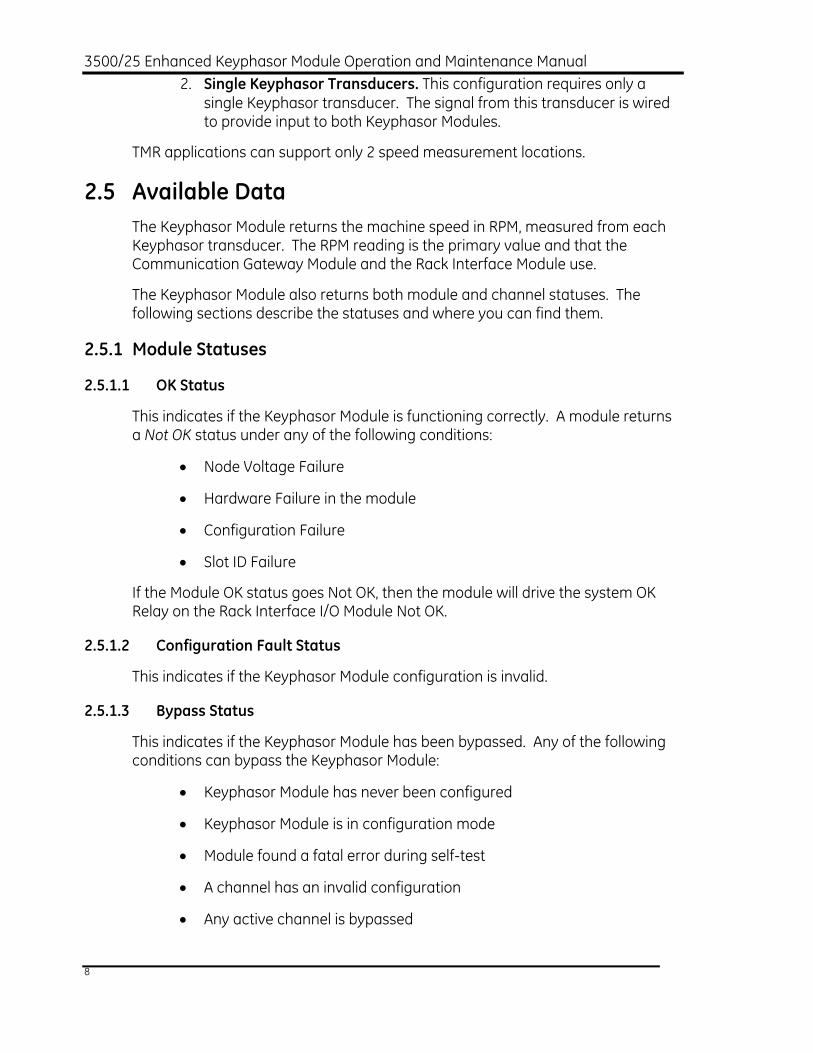
3500/25 Enhanced Keyphasor Module Operation and Maintenance Manual 2. Single Keyphasor Transducers. This configuration requires only a
single Keyphasor transducer. The signal from this transducer is wired to provide input to both Keyphasor Modules.
TMR applications can support only 2 speed measurement locations.
2.5 Available Data The Keyphasor Module returns the machine speed in RPM, measured from each Keyphasor transducer. The RPM reading is the primary value and that the Communication Gateway Module and the Rack Interface Module use.
The Keyphasor Module also returns both module and channel statuses. The following sections describe the statuses and where you can find them.
2.5.1 Module Statuses
2.5.1.1 OK Status
This indicates if the Keyphasor Module is functioning correctly. A module returns a Not OK status under any of the following conditions:
• Node Voltage Failure
• Hardware Failure in the module
• Configuration Failure
• Slot ID Failure
If the Module OK status goes Not OK, then the module will drive the system OK Relay on the Rack Interface I/O Module Not OK.
2.5.1.2 Configuration Fault Status
This indicates if the Keyphasor Module configuration is invalid.
2.5.1.3 Bypass Status
This indicates if the Keyphasor Module has been bypassed. Any of the following conditions can bypass the Keyphasor Module:
• Keyphasor Module has never been configured
• Keyphasor Module is in configuration mode
• Module found a fatal error during self-test
• A channel has an invalid configuration
• Any active channel is bypassed
8

Section 2 - General Information 2.5.1.4 Module Status Locations
Table 2-2 shows the location of the module statuses.
Table 2-2: Module Status Locations
Module Statuses Communication Gateway Module
Rack Configuration Software
Operator Display Software
OK X X
Configuration Fault X
Bypass X
2.5.2 Channel Status
2.5.2.1 OK Status
This indicates whether or not the module has detected a fault on the channel. The following will cause a Channel Not OK status AND a Module Not OK status:
• Node Voltage Failure
• Hardware Failure in the module
• Bypass is active on the channel
• Configuration Failure
• Slot ID Failure
The following will cause only a Channel Not OK status and will NOT cause module to drive the System OK Relay on the Rack Interface I/O Module:
• Keyphasor Signal less than 1 RPM
• Keyphasor Signal greater than 99,999 RPM
• Keyphasor Signal has a 50% or greater Change in Period
• Keyphasor Transducer Failure
• Keyphasor Signal greater than 20 kHz
2.5.2.2 Bypass Status
This indicates if the associated Keyphasor Module channel has been bypassed. Any of the following conditions can bypass a channel:
• Keyphasor Module has never been configured
• Keyphasor Module is in configuration mode
• Module found a fatal error during self-test
9

3500/25 Enhanced Keyphasor Module Operation and Maintenance Manual • A channel has an invalid configuration
• Any active channel is bypassed
2.5.2.3 Off Status
This indicates whether the channel has been turned off. You may use the Rack Configuration Software to turn off the Keyphasor channels.
2.5.2.4 Channel Status Locations
Table 2-3 shows the locations of the channel statuses.
Table 2-3: Channel Status Locations
Channel Statuses Communication Gateway Module
Rack Configuration Software
Operator Display Software
OK X X X
Bypass X X X
Off X X
2.6 LED Descriptions The LEDs on the front panel of the Keyphasor Module indicate the operating status of the module as shown in Figure 2-2. Refer to Section 6.2 for all of the available LED conditions.
1. OK LED: Indicates that the Keyphasor Module and the Keyphasor I/O Module are operating correctly. 2. TX/RX LED: Indicates communication between the Keyphasor Module and the Rack Interface Module as
messages are transmitted and received.
Figure 2-2: Keyphasor Module Front Panel LEDs
10

Section 3 - Configuration Information
3. Configuration Information This section describes how to use the Rack Configuration Software to configure the 3500/25 Keyphasor Module. It also describes the configuration restrictions that are associated with this module. Refer to the 3500 Monitoring System Rack Configuration and Utilities Guide and the Rack Configuration Software for details on how to use the software.
3.1 Hardware Considerations
3.1.1 General
The slots in the rack are numbered from 0 to 15, counting from left to right. The power supplies go into slot 0 and the Rack Interface Module goes into slot 1. Slots 2 through 15 are called “monitoring positions”. You can install the 3500/25 Keyphasor Module into any of the monitoring positions. However, if you will use the 3500/20 Rack Interface Module and Data Manager I/O to interface to the DDIX, TDIX, or TDXnet, refer to the manual on the 3500/20 for details on the slot restrictions that this may place on your configuration.
3.1.2 Paired Keyphasor Signal Hardware Restrictions
In a paired Keyphasor signal application you can insert up to 4 half height Keyphasor Modules which would support up to 8 Keyphasor Module input signals at one time. You can place the 4 Keyphasor Modules in any slot in the rack except those slots designated for the RIM and the Power Supplies. You must, however, place the Keyphasor Modules in adjacent slots with 2 modules in the top half and 2 modules in the bottom half of the rack.
Application Advisory
When using the 3500/25 in a Paired Keyphasor Signal application, your system must have the following or
more recent modules and firmware:
Management 4 Channel Monitors (PWA 140734-XX): Firmware Rev. 2.30
3500/22 Transient Data Interface (PWA 1388607-XX): Firmware Rev. 1.20
11

3500/25 Enhanced Keyphasor Module Operation and Maintenance Manual
3.2 Software Configuration Considerations Although most of the Keyphasor Module configuration options are very straightforward, the increased signal processing options warrant a discussion of some configuration considerations that you should know. This section covers those considerations and introduces some new terms that the Enhanced Keyphasor Module configuration uses.
3.2.1 Keyphasor Module/3500 Monitor Configuration Interaction
The Keyphasor probe orientation and Event Setup configuration parameters are directly linked to monitor operation in the 3500 Rack. When these parameters change, you must download (or re-download) to the 3500 rack the configuration of the monitors that are associated with the changed Keyphasor channels. The Rack Configuration Software displays messages and confirmation dialog boxes to help you properly select the affected monitors to which you should download configuration as appropriate.
3.2.2 Signal Paths and Signal Options
There is an important distinction between the Rack Signal and Buffered Output signal paths, and the selection of Processed and Non-Processed signals that one wishes to place on them. These terms are defined here.
• The Rack Signal path is the Keyphasor signal path that runs down the 3500 System Backplane, for use by monitors in the rack.
• The Buffered Output path is the Keyphasor signal path that runs to the front panel BNC connectors and to the Keyphasor I/O Module Buffered Output terminals.
Note that the Buffered Output signal paths have no bearing on how monitors in the rack handle Keyphasor signals, as the monitors do not operate on the Buffered Output signals. The selection of the signal type put on the Rack Signal path does, however, affect monitor operation as this manual describes.
• Non-Processed signals are simply those signals that have not undergone a change in frequency, from the input transducer signal to the output conditioned signal.
• Processed signals are those signals that have undergone a change in frequency. Processed signals may be at a rate that is higher or lower in frequency than the input transducer signal from which they are derived.
The following example can illustrate the effect of using Processed vs. Non-Processed signals:
12

Section 3 - Configuration Information Suppose that you apply identical, 100 RPM test signals to the inputs of 2 Enhanced Keyphasor Module channels. If you specify the Event Ratio for Channel 1 to be 0.5 and the Event Ratio for Channel 2 to be 2.0, then the Processed signal output on Channel 1 would be at 200 RPM, the Processed signal output for Channel 2 would be at 50 RPM, and the Non-Processed signal on either channel, if selected, would be at 100 RPM.
The Keyphasor signals that the original Keyphasor Module generates are always of the Non-Processed type. The Enhanced Keyphasor Module can produce both Non-Processed and Processed signals.
3.2.3 Event Setup Options
The expanded signal processing capabilities of the Enhanced Keyphasor Module introduces a new configuration parameter known as the Event Setup. This parameter adds the Event Ratio option to the pre-existing Events per Revolution (Events Per Rev) and Recip Multi-Event Wheel configuration options. These 3 options are mutually exclusive and variations of the same theme, as each describes a number of input events seen by the Keyphasor probe relative to a single revolution of some primary rotor.
1. Recip Multi-Event Wheel. This is the most specialized option, and has a fixed value of 13 input events per single rotation of the primary rotor. This option is intended for reciprocating (or recip) machine applications.
2. Events Per Rev. This option allows you to specify 1 to 255 input Keyphasor events per single revolution of some primary rotor.
3. Event Ratio. This option is the most flexible option. It allows you to specify a practically unlimited range for the number of input Keyphasor events per single revolution of some primary rotor (or, more generally, the ratio of the number of input events per generated output events), including fractional numbers. Processed signals are generally synonymous with an Event Ratio Event setup, whereas Non-Processed signals usually imply an Events Per Rev or Recip Multi-Event Wheel Event Setup.
To eliminate redundant specifications of any particular configuration, the Rack Configuration Software automatically reduces an Event Ratio Event Setup to an Events Per Rev Event Setup whenever they would be logically equivalent.
3.2.4 Keyphasor Signal Rate Division by 3500 Monitors
Individual monitors in a 3500 Rack are sensitive to the configuration for Non-Processed Rack Signals in which you specify the Event Setup parameter to be an integer in the range of 2 to 255. It makes no difference whether you option the Event Setup as Events Per Rev, Event Ratio or Recip Multi-Event Wheel. For this particular configuration, the individual monitors that are configured to use such a
13

3500/25 Enhanced Keyphasor Module Operation and Maintenance Manual Keyphasor channel will internally divide the rate of the received Keyphasor pulse train at the individual monitor level. Simply put, individual monitors divide down the Keyphasor signal they receive from the rack signal path by the integer value in the Event Setup numeric input field on the Keyphasor Module configuration screen.
Note that in all cases for which you configure a Keyphasor channel to use a Processed Rack Signal, monitors in the rack that are configured to use that channel will not internally divide the Keyphasor signal rate. This makes sense since the point of using a Processed Rack Signal is to let the Enhanced Keyphasor Module do the work of modifying the incoming signal rate to provide monitors with a "once-per-turn" Keyphasor signal.
3.2.5 Restriction On Availability of Absolute Phase Information
One caution of which you should be aware is that absolute phase information is not available from a monitor channel that uses a Processed Rack Signal, or when the specified Events Per Rev value is other than 1. This is because after the module loses or invalidates a Keyphasor input signal, the re-acquired input signal may or may not correspond with the synchronizing events of past or future sessions from run to run.
To illustrate this, consider that if your system uses an n-tooth gear as the input Keyphasor source, then from run to run the Keyphasor module cannot guarantee that it will observe any specific gear tooth or notch as the "synchronizing event" during the re-synchronization process. So for this reason, the monitor disables phase information (makes the information unavailable and/or marks the information as invalid) when using a Processed Rack Signal, or if the specified Events Per Rev Event value is other than 1. The Recip Multi-Event Wheel option is a special case however, and the system retains phase information with this setup. The Rack Configuration Software displays messages and confirmation dialog boxes to assist you with properly identifying and selecting monitors that would be affected by this constraint.
3.2.6 Phase Accuracy Limitation of Processed Signals
As with any processed signal system, the finite response time limits the precision and accuracy of the generated output Processed Keyphasor signal in response to the input signal. Users of processed signal systems should consider both static and dynamic phase error components, however small they may be. The following discussion covers the phase error specifications for static and dynamic Processed output signals.
The Specifications section of this manual contains more detailed information regarding the Static and Dynamic Phase Error characteristics of the Enhanced Keyphasor Module when generating Processed signals.
14

Section 3 - Configuration Information 3.2.6.1 Static Phase Error
The Static Phase Error ("SPE") of the Processed output signal is the long-term deviation in the output signal that occurs when the system maintains a constant-speed input signal. This deviation is due to unavoidable deviation in algorithm execution time for the DSP to process asynchronous Keyphasor input events, and is limited by the internal DSP clock rate. The Enhanced Keyphasor Module exhibits approximately ±6 µs of fixed, maximum deviation in the output signal over time. Table 3-1 shows some representative performance numbers for Static Phase Error values that you may expect for typical output frequencies across the valid range. Note that as the output frequency decreases the worst-case SPE also decreases in a linear fashion.
Table 3-1: Representative Static Phase Error (SPE) Values
Fout (Hz) RPM/CPM SPE
1667 100,000 ±3.60°
463 27,780 ±1.00°
60 3600 ±0.13°
50 3000 ±0.11°
3.2.6.2 Dynamic Phase Error
The Dynamic Phase Error ("DPE") of the Processed output signal is the short-term deviation in the output signal that results from a changing-speed input signal. This deviation is due to several factors.
1. The signal processing algorithms have an unavoidable natural response latency, due mostly to the DSP’s finite internal clock rate.
2. The Enhanced Keyphasor Module’s algorithms are predictive in nature. This tends to improve the response for frequency division (Event Ratio is greater than or equal to 2.0) and degrade the response for frequency multiplication (Event Ratio is less than 2.0). The Event Ratio strongly affects the dynamic response in a non-linear, natural logarithmic fashion.
3. The Enhanced Keyphasor Module exhibits an essentially linear change in the degrees of phase error per percent change, assuming constant acceleration.
3.2.7 Limitations When Specifying an Events Ratio Setup
The 3500 Configuration Software displays the numeric range to the left of the data entry field for the Event Setup of an Event Ratio as 0.0000001 to 10000000.0. This reflects the valid range of numbers that you may specify for the Event Ratio. This range, for all intents and purposes, should cover any practical user application. Note that the Rack Configuration software automatically performs limit checking to ensure that you enter only numbers within the valid range.
15

3500/25 Enhanced Keyphasor Module Operation and Maintenance Manual Regardless of the Event Ratio you specify, both the input Keyphasor signal and generated Processed Rack Signals have limitations that, among other things, affect the Channel and Module OK Statuses. The Specification section of this manual details these limitations.
You may specify the Event Ratio as a positive, real number (i.e., an integer and/or fractional number) that is either less than or greater than, but not exactly equal to, 1.0. Although the software will not allow you to specify an Event Ratio of exactly 1.0, you can functionally achieve this by specifying the Events Per Rev with a value of 1 with the Event Setup option. This configuration supports the majority of typical customer applications and achieves maximum system performance. This also eliminates what would otherwise be a redundant means of specifying unity Keyphasor rate processing.
Noted that, in general, the system is better able to track the input for higher Event Ratio numeric values, since it has more "information" in the form or input pulses with which to work. This allows the system to better to respond to speed fluctuations or ramping conditions as it tracks the input.
There are a few extra considerations to remember when you specify an Event Ratio less than 2.0. The design of the digital signal processing algorithm uses 2 fundamentally different strategies, one for Event Ratios equal to or greater than 2.0 (which essentially implies frequency division), and the other for Event Ratios less than 2.0 (which implies frequency multiplication). The DSP code automatically selects the algorithm based on the programmed Event Ratio for each channel. The large majority of applications will require the Keyphasor module to use an Event Ration much greater than 2.0 to divide down the input signal. Because of this the DSP code has been optimized to support these applications. This improves the module’s transient response for frequency division, but degrades the response for frequency multiplication. For this reason, you should not expect the Enhanced Keyphasor Module to exhibit any reasonable transient response for Event Ratios approaching or less than 2.0.
Frequency multiplication processing has 2 additional side effects that are not present when you specify an Event Ratio of 2.0 or greater. These 2 side-effects are similar in effect and result from the limitations that are inherent in attempting to generate multiple output pulses in response to a single input pulse (or sequence of pulses), which is the essence of frequency multiplication.
1. The Enhanced Keyphasor Module may require a significant amount of synchronization time from when a signal is first applied to the input to a Keyphasor channel to when the first Processed Signal output appears. Generally speaking, the more significant digits you specify to the right of the decimal point in the Event Ratio, the longer the DSP may take to synchronize to the input and generate output pulses in response.
2. When the Enhanced Keyphasor Module loses the input Keyphasor signal, a multiplied output at the programmed rate may persist for some time after the input stimulus is lost.
16

Section 3 - Configuration Information These side effects may persist for 2 minutes or more.
3.3 Software Configuration Options This section discussed the Keyphasor Module configuration options in detail. In addition to describing the options, this section provides figures that depict screen views of the 3500 Rack Configuration software. Several examples illustrate the various option choices on the Keyphasor Module configuration screen. Depending on the numeric values entered for some configuration parameters, the Rack Configuration Software may restrict certain options, make options unavailable, and/or automatically "force-select" some options.
3.3.1 Keyphasor Module Configuration Options
Figure 3-1: Keyphasor Module Configuration Screen
3.3.1.1 REFERENCE INFORMATION
These fields are shown at the top of the Configuration Screen and contain information that indicate the location of the Keyphasor Module in the 3500 Rack, the type of associated Keyphasor I/O Module, and an optional label for you to track configuration setups. Note that you must select the I/O Module parameter as part of the configuration setup.
17

3500/25 Enhanced Keyphasor Module Operation and Maintenance Manual ConfigID
This information field displays an optional identifier of up to six characters, which if present was entered upon last configuration download to the module.
Slot
This information field indicates the slot monitoring position of the Keyphasor Module in the 3500 Rack.
Keyphasor Position
This information field identifies where the Keyphasor Module is physically located in the 3500 Rack, either in the Upper or Lower slot.
I/O Module
This user-input field specifies the type of interface module used to connect the transducers to the Keyphasor Main Module. Internal and External Termination options refer to the wiring points of the transducers, which either wire directly to the I/O module (Internal type) or to an external termination block (External type). The Barrier I/O type is offered only as an Internal Termination type, and does not support the Magnetic Pickup transducer type option. The Isolated types provide transformer isolation of the input channels from the rack common and from each other. The available Keyphasor I/O Module options are as follows:
• Keyphasor I/O Module (Internal Termination)
• Keyphasor Barrier I/O
• Keyphasor I/O Module (External Termination)
• Isolated Keyphasor I/O (Internal Termination)
• Isolated Keyphasor I/O (External Termination)
Output Assignment
This option is only available for paired Keyphasor configuration. Since 2 Keyphasor modules (with a total of 4 outputs) must share only 2 outputs, you can configure each paired Keyphasor only in a primary/backup manner, allowing each module only 1 output assignment. For the module, select channel 1 or channel 2 to be this assignment. The user must select this assignment.
Input Assignment
This option is only available for paired Keyphasor configuration. As described previously, output assignment is restricted to 1 channel only for paired Keyphasor configurations. The two inputs must be defined as primary &
18

Section 3 - Configuration Information backup. The choice is channel 1 = Primary / channel 2 = Backup OR channel 2 = Primary / channel 1 = Backup. The user must select this assignment.
3.3.1.2 CHANNEL CONFIGURATION
You may configure the 2 channels of a Keyphasor Module independently of each other, per the following configuration options. The software specifies the Channel 1 options in the left half of the Configuration Screen, below the Reference Information fields. Channel 2 options are specified in the right half.
Active (Channel Activity)
This check box enables or disables a Keyphasor channel. If you will not connect a Keyphasor transducer to this channel, then you should uncheck this box.
Signal Polarity
Notch
Select the Notch option if the module will use the leading edge of a negative-going pulse in the input signal to produce an output pulse for use by the monitors. A notch in a shaft will cause a Keyphasor transducer to produce this type of input pulse. If you plan to use a magnetic pickup, you should set the Notch/Projection setting to Notch, as in most cases the installation will clip the positive portion of the signal.
Projection
Select the Projection option if the module will use the leading edge of a positive-going pulse in the input signal to produce an output pulse for use by the monitors. A notch in a shaft will cause a Keyphasor transducer to produce this type of input pulse.
Type (Transducer Type)
Proximitor
Select the Proximitor option if the installation uses a Proximitor or similar type of transducer to supply the Keyphasor signal for this channel.
Magnetic
Select the Magnetic option if the installation uses a magnetic pickup type of transducer to supply the Keyphasor signal for this channel. Magnetic pickups require a shaft rotative speed of at least 200 RPM (3.3 Hz).
Buffered Output
The design of the Keyphasor module routes the Buffered Output signal for a given channel to the Keyphasor Module front panel BNC connector and to the Keyphasor I/O Module Buffered Output terminal.
19

3500/25 Enhanced Keyphasor Module Operation and Maintenance Manual Non-Processed
Select this option if the Buffered Output signal will be "Non-Processed".
Processed
Select this option if the Buffered Output signal will be "Processed".
Rack Signal
The 3500 Monitor System design routes the Rack Signal for a given channel down the 3500 System Backplane for use by monitors in the rack.
Non-Processed
Select this option if the Rack Signal will be "Non-Processed".
Processed
Select this option if the Rack Signal will be "Processed".
Hysteresis
Hysteresis is the difference in the input signal between the voltage levels where the Keyphasor pulse turns on and where it turns off. The larger the hysteresis value, the greater the immunity will be to noise on the input signal. See Figure 3-2.
1. Analog Input Signal 2. Digital Output Keyphasor Signal 3. Threshold 4. Hysteresis
Figure 3-2: Example of Signal Hysteresis
Threshold
The value at which the Keyphasor pulse would turn on and off if the Hysteresis was zero.
Auto
The module automatically sets the trigger threshold to a value midway between the most positive peak and the most negative peak of the input
20

Section 3 - Configuration Information signal. This threshold option tracks changes in the input signal. Auto threshold requires a minimum signal amplitude of 2 Vpp and a minimum frequency of 120 RPM (2 Hz).
Manual
You may set the Manual trigger threshold to any value in the range of -20.0 to 0.0 volts.
Adjust
The software makes this option available when you select Manual Threshold. The software displays a dialog box to aid you in setting the Manual Threshold value.
Event Setup
Events Per Rev
This option specifies the number of pulses in a Keyphasor transducer input signal for each shaft revolution (rotation). If the Keyphasor transducer is observing a single notch or projection, set the Events Per Rev value to 1. If the Keyphasor transducer is observing a multi-tooth gear, set the Events Per Rev value to the number of teeth on the gear. The available range is 1 to 255. Figure 3-3 shows the maximum settings for Events Per Rev. Figure 3-4 and Figure 3-5 depict typical applications.
1. RPM 2. Events Per Revolution 3. Upper RPM Limit is 99999 4. Upper Frequency Limit is 20 kHz
Figure 3-3: Maximum Events Per Revolution
21

3500/25 Enhanced Keyphasor Module Operation and Maintenance Manual
Application Advisory
You can use signals from a Keyphasor transducer observing a multi-tooth gear (except for Recip Multi-Event Wheel) only
for speed measurements and not for phase measurements.
1
2
3
1. Probe A 2. Probe B 3. Shaft with notch
Figure 3-4: Events Per Rev Value Typically Set to 1 (Phase Available)
1
2
3
1. Probe A 2. Probe B 3. 24-tooth gear
Figure 3-5: Events Per Rev Value Typically Set to 24 (Phase Not Available)
22

Section 3 - Configuration Information Recip Multi-Event Wheel
This option is for reciprocating machine applications in which the Keyphasor transducer observes a specially designed 13-tooth gear whose design incorporates a distinguishable once-per-turn event.
Event Ratio
This option specifies the ratio of the number of input pulses to the number of desired output pulses in a Processed Keyphasor signal. The input pulses are from a Keyphasor transducer observing a shaft or gear. The output pulses are generated by the DSP in an Enhanced Keyphasor Module as the Event Ratio specifies. You can specify the Event Ratio value to be any positive, real number in the range from 0.0000001 to 10000000, other than exactly 1.0. The precision of the Event Ratio can be at least 7 significant decimal digits. The Setup dialog box allows you to specify the Event Ratio in terms of an integer numerator and denominator.
Application Advisory
You can use Processed Keyphasor signals that use the Event Ratio Event
Setup option only for speed measurements only and not for phase
measurements.
Orientation
This option specifies the location of the transducer relative to the shaft. The orientation angle is 0º to 180º left or right as observed from the driver to the driven end of the machine train. The following figure shows this for horizontal shafts.
23

3500/25 Enhanced Keyphasor Module Operation and Maintenance Manual
1 2
4
57
6
3
1. Shaft 2. Driven end 3. Driver end 4. 0 degrees 5. 90 degrees right 6. 180 degrees 7. 90 degrees left
Figure 3-6: Transducer Orientation On Horizontal Shaft
Upper RPM Limit
This specifies the full-scale maximum RPM value for the module to use when reporting channel RPM data to the Communication Gateway and Operator Display software.
RPM Clamp Value
This specifies the fixed RPM value for the Communication Gateway to provide when the channel is Not OK or is bypassed.
3.3.2 Keyphasor Module Configuration Screen Examples
This section provides some examples of the Keyphasor Module configuration screen for various configurations.
3.3.2.1 Keyphasor Module Configuration Screen Example 1
Figure 3-7 shows the default "Events Per Rev" Event Setup option, with the Number of Events value set to 1. The Channel 2 configuration is identical to that for Channel 1.
24

Section 3 - Configuration Information
Figure 3-7: Default Keyphasor Module Configuration Screen
3.3.2.2 Keyphasor Module Configuration Screen Example 2
Figure 3-8 shows an "Event Ratio" for the Event Setup on Channel 1 and Figure 3-9 shows a "Recip Multi-Event Wheel" for the Event Setup on Channel 2.
For Channel 1, the Event Setup allows you to select the Buffered Output as Non-Processed or Processed, which is always the case when you select the Event Ratio Event Setup. The Rack Signal is force-selected as type Processed, since the Event Ratio is non-integer.
For Channel 2, the Event Setup forces both the Buffered Output and Rack Signal paths types to be Non-Processed, which is always the case for the Recip Multi-Event Wheel option.
Figure 3-8: Keyphasor Module Configuration Screen With Event Ratio Option
25

3500/25 Enhanced Keyphasor Module Operation and Maintenance Manual
Figure 3-9: Keyphasor Module Configuration Screen With Recip Multi-Event Wheel
Option
3.3.2.3 Keyphasor Module Configuration Screen Example 3
Figure 3-10 shows an "Events Per Rev" Event Setup on Channel 1 and Figure 3-11 shows an "Event Ratio" Event Setup on Channel 2.
For Channel 1, this Event Setup forces both the Buffered Output and Rack Signal to be Non-Processed, which is always the case for the Events Per Rev option.
For Channel 2, you may option both the Buffered Output and Rack Signal for Non-Processed or Processed, since the Event Ratio is an integer in the range 2 to 255 (in this case, 5).
Figure 3-10: Keyphasor Module Configuration Screen with Event Per Rev Option
26

Section 3 - Configuration Information
Figure 3-11: Keyphasor Module Configuration Screen With Event Ratio Value of 5
3.3.2.4 Keyphasor Module Configuration Screen Example 4
Figure 3-12 specifies an input-multiplying "Event Ratio" Event Setup on Channel 1 and Figure 3-13 an input-dividing "Event Ratio" Event Setup on Channel 2.
In both cases, the software forces the Rack Signal to be Processed, since the specified Event Ratio values are not integers.
Figure 3-12: Keyphasor Module Configuration Screen With Non-Integer Event Ratio
Value Less Than 1 (Input Multiplier)
27

3500/25 Enhanced Keyphasor Module Operation and Maintenance Manual
Figure 3-13: Keyphasor Module Configuration Screen With Non-Integer Event Ratio
Value Greater Than 1 (Input Divider)
3.3.3 Paired Keyphasor Signal Configuration
Using the Rack Configuration Software to configuring the 3500/25 module for a Paired Keyphasor application is similar to using the software to configure the module for a Standard application. The following items may help you avoid confusion during the configuration process.
• “Output Assignment” refers to the system Keyphasor line that the configured module will drive. There are 4 system lines. In Paired Keyphasor mode you must specify a different “Output Assignment” for each module.
• “Input Assignment” defines the priority of the signals input into the Keyphasor module. This value determines the primary and backup signal within the Keyphasor module you are configuring.
• The “Input Active” setting allows you to either enable or disable the monitoring functionality that relates to each channel in the Keyphasor module.
• You can no longer configure output activity. The output activity in a paired Keyphasor application is based on the “Input Assignment”, “Output Assignment”, and the validity, or OK state, of the Keyphasor inputs.
When configuring the 3500 Rack configuration Software you should consider the following items:
28

Section 3 - Configuration Information • The Rack Configuration Software will not allow you to download a
configuration that has more than 2 Keyphasor Modules in the upper or the lower half of the rack.
• The Rack Configuration Software will not allow you to download a configuration that has a Paired Keyphasor and a Standard Keyphasor configuration in either the upper or the lower half of the rack simultaneously. If you need both Paired Keyphasor and Standard Keyphasor capabilities within a rack, you must use the Paired Keyphasor configuration in the upper/lower half of the rack and the Standard Keyphasor configuration in the opposite half of the rack.
• The Rack Configuration software will not allow you to use more than 2 slots for Keyphasor modules. If you place 2 Keyphasor modules in the upper half of the 3500 rack and wish to place either 1 or 2 additional Keyphasor modules in the lower half of the rack, you must place the modules in the same slots that have Keyphasor modules in the upper half of the rack.
• If you associate multiple monitors with 1 paired Keyphasor module, you must configure these monitors to have the same primary and backup Keyphasor association.
• The 3500 system places restrictions upon Paired Keyphasor applications because the system uses inputs as a primary/backup set for 1 system line. These restrictions require that the 2 Keyphasor inputs have input signals with the same events per revolution or be conditioned to have the same events per revolution before being placed on the system line. To accomplish this, you must configure the Keyphasor modules to ensure one of the following conditions:
1) Both channels will have an input with the same events per revolution and module will process neither channel.
2) The module will process both Channel 1 and Channel 2.
3) The module will process one channel and the other channel will have a 1 event per revolution input.
3.3.4 Paired Keyphasor Signal Configuration Screen Examples
To make Paired Keyphasor Signal Capability available, you must place and configure the Keyphasor modules as shown in Figure 3-14.
29

3500/25 Enhanced Keyphasor Module Operation and Maintenance Manual
Figure 3-14: Paired Keyphasor Signal Configuration Setup
After selecting 1 of the 3 configurations (Upper, Lower, or Upper and Lower) shown in Figure 3-14, you can use the options menu to configure each Keyphasor Module.
Figure 3-15: Configuring the Keyphasor Module
3.3.5 Software Switches
The Keyphasor Module supports software switches that you can use to further control the operation of the module as a whole or on an individual channel basis. These switches let you temporarily bypass, enable or cancel monitor and/or channel functions. You access these switches by selecting Utilities/Software Switches… from the main menu screen of the Rack Configuration software.
30

Section 3 - Configuration Information
Figure 3-16: Keyphasor Module Software Switches
The following 2 special notes apply to the use of Software Switches.
1. The Software Switch control screen that the Rack Configuration Software shows is common to all the available 3500 System module types. Not all the different types of software switches in this screen apply to the Keyphasor Module. The Keyphasor Module will respond to only the software switch options that this section presents.
2. Software Switch changes do not take effect until you click the Set button.
3.3.6 Software Switch Options
3.3.6.1 Module Switches
These switches affect the Keyphasor Module as a whole. The 3500 Monitoring System uses module switch number in the Communication Gateway or Display Interface Module, as shown in Table 3-2.
Table 3-2: Module Switch Numbers
Module Switch Number Switch Name
1 Configuration Mode
4 Manual Keyphasor Threshold Adjust Mode
31

3500/25 Enhanced Keyphasor Module Operation and Maintenance Manual Configuration Mode
This switch reflects the Configuration Mode status of the Keyphasor Module. When the Rack Configuration Software downloads a configuration, it will automatically enable and disable this switch. If the software loses its connection to the rack during the configuration process, you can use this switch to remove the module from Configuration Mode.
Manual Keyphasor Threshold Adjust Mode
This switch reflects the Manual Keyphasor Threshold Adjust Mode status of the Keyphasor Module. If Manual Threshold is selected, the software will automatically enable and disable this switch when you click on the Threshold Adjust… button on the Keyphasor Module Configuration Screen. While in this mode, the Keyphasor Module will operate with a temporary Manual Threshold that the Rack Configuration software supplies. Note that monitor values that use the affected Keyphasor signals, such as 1X amplitude and phase, may go invalid while you are adjusting the Manual Threshold value. If the software loses its connection to the rack during the adjustment process, you can use this switch to remove the module from Manual Keyphasor Threshold Adjust Mode.
3.3.6.2 Channel Switches
These switches affect the Keyphasor Module on an individual channel basis. The 3500 Monitoring System uses the channel switch number in the Communication Gateway or Display Interface Module, as shown in Table 3-3.
Table 3-3: Channel Switch Numbers
Channel Switch Number Switch Name
4 Bypass
Bypass
When you enable this switch, the module will invalidate the RPM value for the channel and bypass the signal conditioning for the channel.
32

Section 4 - Keyphasor I/O Module Descriptions
4. Keyphasor I/O Module Descriptions The Keyphasor I/O Modules are full-height rack modules that receive signals from the Keyphasor transducers and route these signals to the Keyphasor Main Module (or Modules). The I/O Modules provide power to the Keyphasor transducers, and provide conditioned Keyphasor output signals via their Buffered Output terminals. Applications typically use these buffered outputs to provide Keyphasor signals to external equipment, such as TDIX or TDXnet.
You may install 1 or 2 Keyphasor Main Modules in the upper and/or lower half of any single "monitoring position" in the rack. For paired signal Keyphasor configuration, the 2 paired Keyphasors must occupy adjacent rack slots. You may install Keyphasors that are configured for paired operation in the upper and lower half-slots of any 2 adjacent “monitoring positions” in the rack. You then install 1 full-height Keyphasor I/O Module behind this slot (if installed in a Rack Mount or a Panel Mount rack) or above this slot (if installed in a Bulkhead rack). For paired signal Keyphasor configurations you install 2 I/O modules, with 1 module behind or above each slot that contains a Keyphasor Main Module.
5 different types of Keyphasor I/O Modules are available, which cover the various options for internal or external terminations, type of terminations, signal isolation or non-isolation, and use of intrinsic safety barriers or not. Table 4-1 and Table 4-2 summarize the available Keyphasor I/O Module options.
Table 4-1: Internal Termination I/O Module Options
I/O Module Options (See Note 1)
Non-Isolated Keyphasor I/O Module
Isolated Keyphasor I/O Module
Internal Barrier Keyphasor I/O Module
Table 4-2: External Termination I/O Module Options
I/O Module Options (See Note 2)
Non-Isolated Keyphasor I/O Module
Isolated Keyphasor I/O Module
Notes:
1. All Internal Termination Keyphasor I/O Modules use Euro Style connectors.
2. All External Termination Keyphasor I/O Modules use an External Termination Block. External Termination Blocks are available with either Euro Style connectors or Terminal Strip connectors.
This section of the manual describes how to use the connectors on the various Keyphasor I/O Modules. It also lists part numbers of which cables to use and shows cable signal pin-outs.
33

3500/25 Enhanced Keyphasor Module Operation and Maintenance Manual Refer to the following additional documentation for assistance with module wiring and mounting details.
• The 3500 Field Wiring Diagram Package (part number 130432-01) shows how to connect Keyphasor transducers to the Keyphasor I/O Modules or to External Termination Blocks.
• The 3500 Monitoring System Rack Installation and Maintenance Manual (part number 129766-01) shows how to mount External Termination Blocks.
4.1 Internal Termination Keyphasor I/O Modules For Internal Termination Keyphasor I/O Modules you must wire each Keyphasor transducer to the I/O Module individually. This section shows what the different Internal Termination Keyphasor I/O Modules look like and how to connect the wires to the Euro Style connectors that these modules use.
4.1.1 Non-Isolated Internal Termination Keyphasor I/O Module
1. Connect wires here for the Keyphasor transducer associated with Upper Keyphasor Main Module, Channel 1. 2. Connect wires here for external equipment (such as TDIX/TDXnet) associated with Upper Keyphasor Main Module,
Channels 1 and 2. 3. Connect wires here for the Keyphasor transducer associated with Lower Keyphasor Main Module, Channel 2. 4. Connect wires here for external equipment (such as TDIX/TDXnet) associated with Lower Keyphasor Main Module,
Channels 1 and 2. 5. Connect wires here for the Keyphasor transducer associated with Lower Keyphasor Main Module, Channel 1. 6. Connect wires here for the Keyphasor transducer associated with Upper Keyphasor Main Module, Channel 2.
Figure 4-1: Non-Isolated Internal Termination Keyphasor I/O Module
34

Section 4 - Keyphasor I/O Module Descriptions
4.1.2 Isolated Internal Termination Keyphasor I/O Module
The Isolated Internal Termination Keyphasor I/O Module passes input signals through transformers to provide true isolation for 4 Keyphasor channels. The primary side of each transformer is not referenced to ground and therefore provides isolation that removes potential ground loops present in installations that connect numerous systems in parallel. The modules also give transformer-coupled signals a -10 Vdc offset after they pass through the transformers. This improves the range of input signals that you can apply to the Keyphasor Main Module without internal clipping. The design of the Isolated I/O module is specifically for Magnetic Pickup applications, but will work with and provide isolation for Proximitor® sensor applications as long as you provide an external power supply. You should also note that the primary intent of this I/O module was for shaft speed and not phase measurements. You can use it for phase measurements, but you should note that this I/O module introduces a slightly higher phase shift than the Non-Isolated module. Refer to Section 8) for the specific phase shift associated with this I/O at different frequencies.
1. Connect wires here for the Keyphasor transducer associated with Upper Keyphasor Main Module, Channel 1. 2. Connect wires here for external equipment (such as TDIX/TDXnet) associated with Upper Keyphasor Main Module,
Channels 1 and 2. 3. Connect wires here for the Keyphasor transducer associated with Lower Keyphasor Main Module, Channel 2. 4. Connect wires here for external equipment (such as TDIX/TDXnet) associated with Lower Keyphasor Main Module,
Channels 1 and 2. 5. Connect wires here for the Keyphasor transducer associated with Lower Keyphasor Main Module, Channel 1. 6. Connect wires here for the Keyphasor transducer associated with Upper Keyphasor Main Module, Channel 2.
Figure 4-2: Isolated Internal Termination Keyphasor I/O Module
35

3500/25 Enhanced Keyphasor Module Operation and Maintenance Manual
4.1.3 Internal Barrier Internal Termination Keyphasor I/O Module
The Internal Barrier Internal Termination Keyphasor I/O Module provides 4 channels of intrinsically safe signal conditioning for Keyphasor transducers. The module has 2 internally mounted zener barrier modules, 1 barrier module for each pair of transducer channels. Systems that use the Internal Barrier Internal Termination Keyphasor I/O Module require a 3500 Earthing Module to provide an intrinsically safe earth connection. Refer to the 3500 Monitoring System Rack Installation and Maintenance Manual (part number 129766-01) for system requirements for applications that use the Internal Barrier Internal Termination Keyphasor I/O Module.
1. Connect wires here for the Keyphasor transducers associated with Lower Keyphasor Main Module, Channels 1
and 2. Note that these channels are referred to as Channels 3 and 4, respectively, from the point of view of the I/O Module.
2. Connect wires here for external equipment (such as TDIX/TDXnet) associated with Lower Keyphasor Main Module Channels 1 and 2.
3. Connect wires here for the Keyphasor transducers associated with Upper Keyphasor Main Module Channels 1 and 2.
4. Connect wires here for external equipment (such as TDIX/TDXnet) associated with Upper Keyphasor Main Module Channels 1 and 2.
Figure 4-3: Internal Barrier Internal Termination Keyphasor I/O Module
4.1.4 Euro Style Connectors
It is often easier for you to wire connections to a Euro Style connector by removing the connector terminal block from its base, making the connections at the terminal block, and then securing the terminal block back to its base. To remove a Euro Style connector terminal block from its base, loosen the screws
36

Section 4 - Keyphasor I/O Module Descriptions attaching the terminal block to the base, grip the block firmly and pull. Do not pull the block out by its wires because this could loosen or damage the wires or connector.
Figure 4-4: Typical Module With Euro Style Connectors
Refer to the 3500 System Field Wiring Diagram Package (part number 130432-01) for the recommended wiring.
Remove no more than 6 mm (0.25 inches) of insulation from the wires.
Figure 4-5: Connecting Field Wiring to a Euro Style Connector
4.2 External Termination Keyphasor I/O Modules External Termination Keyphasor I/O Modules simplifies the wiring to the Keyphasor I/O Modules in a 3500 Rack by using a 9-pin cable to route the signals from 2 Keyphasor transducers to the Keyphasor I/O Module. This section
37

3500/25 Enhanced Keyphasor Module Operation and Maintenance Manual describes the External Termination Keyphasor I/O Modules and the External Termination Block. It also includes signal pin outs of the cables that connect the External Termination Keyphasor I/O Modules and the External Termination Block.
4.2.1 Non-Isolated External Termination Keyphasor I/O Module
1. Connect the 9-pin cable (part number 129530-XXXX-XX) here for the External Termination Block associated with
Upper Keyphasor Main Module, Channels 1 and 2. 2. Connect the 9-pin cable (part number 129530-XXXX-XX) here for the External Termination Block associated with
Lower Keyphasor Main Module, Channels 1 and 2. 3. Connect wires here for external equipment (such as TDIX/TDXnet) associated with Lower Keyphasor Main Module,
Channels 1 and 2. 4. Connect wires here for external equipment (such as TDIX/TDXnet) associated with Upper Keyphasor Main Module,
Channels 1 and 2.
Figure 4-6: Non-Isolated External Termination Keyphasor I/O Module
4.2.2 Isolated External Termination Keyphasor I/O Module
The Isolated External Termination Keyphasor I/O Module passes the input signals through transformers to provide true isolation for 4 Keyphasor channels. The primary side of each transformer is not referenced to ground and therefore provides isolation that removes potential ground loops present in installations that connect numerous systems in parallel. The module also gives
38

Section 4 - Keyphasor I/O Module Descriptions transformer-coupled signals a -10 Vdc offset after they pass through the transformers. This improves the range of input signals that you can apply to the Keyphasor Main Module without internal clipping. The design of the Isolated I/O module is specifically for Magnetic Pickup applications, but will work with and provide isolation for Proximitor applications as long as you provide an external power supply. You should also note that the primary intent of this I/O module was for shaft speed and not phase measurements. You can use it for phase measurements, but you should note that this I/O module introduces a slightly higher phase shift than the Non-Isolated module. Refer to section 8) for the specific phase shift associated with this I/O at different frequencies.
1. Connect the 9-pin cable (part number 129530-XXXX-XX) here for the External Termination Block associated with
Upper Keyphasor Main Module, Channels 1 and 2. 2. Connect the 9-pin cable (part number 129530-XXXX-XX) here for the External Termination Block associated with
Lower Keyphasor Main Module, Channels 1 and 2. 3. Connect wires here for external equipment (such as TDIX/TDXnet) associated with Lower Keyphasor Main Module,
Channels 1 and 2. 4. Connect wires here for external equipment (such as TDIX/TDXnet) associated with Upper Keyphasor Main Module,
Channels 1 and 2.
Figure 4-7: Isolated External Termination Keyphasor I/O Module
39

3500/25 Enhanced Keyphasor Module Operation and Maintenance Manual
4.2.3 External Termination Blocks
The External Termination Keyphasor I/O Modules can use 2 types of External Termination Blocks:
1) the Keyphasor External Termination Block with Terminal Strip Connectors, and
2) the Keyphasor External Termination Block with Euro Style Connectors.
4.2.3.1 Keyphasor External Termination Block With Terminal Strip Connectors
1. Connect wires here for the Keyphasor transducers. 2. Connect the 9-pin cable(s) (part number 129530-XXXX-XX) here for the External Termination Keyphasor I/O
Module. The 2 cable connectors are labeled Top and Bottom corresponding to the associated Upper and Lower Keyphasor Main Modules, respectively.
3. Use this set of terminals for wiring to Lower Keyphasor Main Module, Channels 1 and 2. 4. Use this set of terminals for wiring to Upper Keyphasor Main Module, Channels 1 and 2.
Figure 4-8: Keyphasor External Termination Block With Terminal Strip Connectors
40

Section 4 - Keyphasor I/O Module Descriptions 4.2.3.2 Keyphasor External Termination Block With Euro Style Connectors
1. Connect wires here for the Keyphasor transducers. 2. Connect the 9-pin cable(s) (part number 129530-XXXX-XX) here for the External Termination Keyphasor I/O
Module. The 2 cable connectors are labeled Top and Bottom corresponding to the associated Upper and Lower Keyphasor Main Modules, respectively.
3. Use this set of terminals for wiring to Lower Keyphasor Main Module, Channels 1 and 2. 4. Use this set of terminals for wiring to Upper Keyphasor Main Module, Channels 1 and 2.
Figure 4-9: Keyphasor External Termination Block With Euro Style Connectors
4.2.4 External Termination Block Cable Signal Pinouts
The following shows the signal pinouts used to connect Keyphasor transducer signals from Keyphasor External Termination Blocks to External Termination Keyphasor I/O Modules. The cable is part number 129530-XXXX-XX.
41

3500/25 Enhanced Keyphasor Module Operation and Maintenance Manual
1 2
3 3 1. Male Keyphasor I/O connector, J1 2. Male external termination (ET) block connector, J2 3. Shield to connector shell
Figure 4-10: External Termination Block Cable Signal Pinouts
42

Section 5 - Maintenance
5. Maintenance The design of the printed circuit boards and components inside 3500 Modules, including the Keyphasor Module, cannot be repaired in the field. Maintenance of 3500 Rack modules consists of testing module channels to verify that they are operating correctly, and replacing a faulty module with a spare. This section describes how to verify correct operation of a Keyphasor Module.
When performed properly, you may install the Keyphasor Module into or remove the module from the rack while power is applied to the rack. Refer to the 3500 Monitoring System Rack Installation and Maintenance Manual (part number 129766-01) for the proper procedure.
Application Advisory
You may lose machinery protection while performing Keyphasor Module
maintenance operations.
5.1 Verifying Keyphasor Module Operation The 3500 Monitoring System is a high-precision instrument that requires no calibration. You must, however, verify the functions of Keyphasor Module channels at regular intervals. At each maintenance interval, we recommend that that you exercise the procedures in this section to verify the operation of all active channels in the Keyphasor Module.
5.1.1 Choosing a Maintenance Interval
• Start with an interval of one year and then shorten the interval if any of the following conditions apply:
- The monitored machine is classified as critical.
- The 3500 Rack is operating in a harsh environment, such as that of extreme temperatures, high humidity or corrosive atmospheres.
• At each interval, use the results of the previous verifications and ISO Procedure 10012-1 1992(E) to adjust the interval.
5.1.2 Required Verification Test Equipment
The equipment that you will need to conduct module verification testing consists of:
• Signal function generator
43

3500/25 Enhanced Keyphasor Module Operation and Maintenance Manual • Multimeter
• DC power supply
• Laptop or other computer running 3500 Rack Configuration Software
5.1.3 Typical Verification Test Setup
Figure 5-1 shows the typical test setup for verifying a Keyphasor Module. The signal function generator and dc power supply simulate the transducer signal and dc bias input to the module. The multimeter is useful for verifying signal levels. The laptop computer is for you to observe the output from the Rack Configuration Software during the tests. You also use it to save the current rack configuration prior to conducting the tests, and to restore the saved configuration afterwards.
1 4
32
1. 3500 Rack 2. Signal generation / verification test equipment 3. RS-232 communications cable 4. Laptop computer running 3500 Rack Configuration Software
Figure 5-1: General Layout for Maintenance Testing
You can connect transducers to a 3500 Rack in a variety of ways. Depending on the type of Keyphasor I/O Module you are using, connect the test equipment to the Keyphasor transducer input terminals per Figure 5-2.
44

Section 5 - Maintenance
1
2 3 4 5
1. Location of Keyphasor transducer input terminals on various I/O modules and termination blocks. 2. Internal Barrier Internal Termination Keyphasor I/O Module. 3. Internal Termination Keyphasor I/O Module (Non-Isolated or Isolated). 4. Keyphasor External Termination Block With Euro Style Connectors (used with External Termination Keyphasor I/O
Modules). 5. Keyphasor External Termination Block With Terminal Strip Connectors (used with External Termination Keyphasor
I/O Modules).
Figure 5-2: Location of Keyphasor Transducer Input Terminals
5.1.4 Using 3500 Rack Configuration Software For Verification Testing
To perform the test procedures described in this section you must be familiar with the following features of the 3500 Rack Configuration Software:
• Uploading, Saving and Downloading of Configuration Files
• Display of the Verification Utility Screen
The 3500 Monitoring System Rack Configuration and Utilities Guide (part number 129777-01) explains how to perform these operations.
NOTE
It is important that you save the original rack configuration before performing any maintenance or troubleshooting
procedures and restore the rack configuration to its original state
afterwards.
45

3500/25 Enhanced Keyphasor Module Operation and Maintenance Manual Figure 5-3 depicts a typical screen view of the 3500 Rack Configuration Software, Verification Utility Screen. You may access this screen by selecting Utilities/Verification… from the main menu screen of the 3500 Rack Configuration Software.
Figure 5-3: 3500 Rack Configuration Software Verification Utility Screen
The module channel verification procedure uses the information displayed on this screen.
5.1.5 Procedure For Verifying Keyphasor Module Channels
This section shows how to verify correct operation of Keyphasor Module channels. This procedure tests the Threshold, RPM, and OK Status values for each channel of the Keyphasor Module. You verify and check the values by varying the input Keyphasor signal frequency and the applied dc bias and then observing that the 3500 Rack Configuration Software Verification screen reports the correct results on the test computer. Refer to Figure 5-4.
NOTE
Test equipment outputs should be floating relative
to earth ground.
46
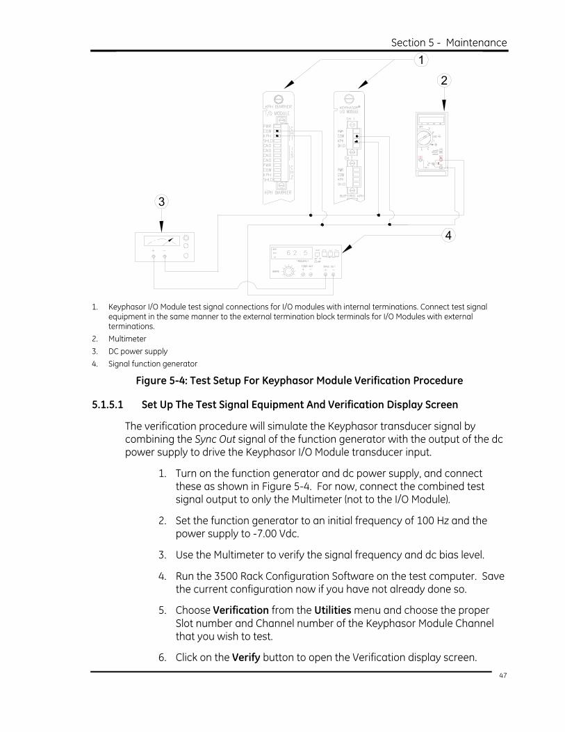
Section 5 - Maintenance
1
2
3
4
1. Keyphasor I/O Module test signal connections for I/O modules with internal terminations. Connect test signal
equipment in the same manner to the external termination block terminals for I/O Modules with external terminations.
2. Multimeter 3. DC power supply 4. Signal function generator
Figure 5-4: Test Setup For Keyphasor Module Verification Procedure
5.1.5.1 Set Up The Test Signal Equipment And Verification Display Screen
The verification procedure will simulate the Keyphasor transducer signal by combining the Sync Out signal of the function generator with the output of the dc power supply to drive the Keyphasor I/O Module transducer input.
1. Turn on the function generator and dc power supply, and connect these as shown in Figure 5-4. For now, connect the combined test signal output to only the Multimeter (not to the I/O Module).
2. Set the function generator to an initial frequency of 100 Hz and the power supply to -7.00 Vdc.
3. Use the Multimeter to verify the signal frequency and dc bias level.
4. Run the 3500 Rack Configuration Software on the test computer. Save the current configuration now if you have not already done so.
5. Choose Verification from the Utilities menu and choose the proper Slot number and Channel number of the Keyphasor Module Channel that you wish to test.
6. Click on the Verify button to open the Verification display screen.
47

3500/25 Enhanced Keyphasor Module Operation and Maintenance Manual 5.1.5.2 Verify Keyphasor Threshold Value
The Keyphasor Threshold value is the input voltage level at which the Keyphasor signal will turn on. This value can be set automatically or manually. Use the following procedure to verify that the Keyphasor Threshold is working correctly.
1. Disconnect the PWR, COM, and KPH wiring from the Channel 1 terminals on the Keyphasor I/O Module or External Termination Block.
2. Connect the test signal to the Keyphasor I/O Module or External Termination Block as shown in Figure 5-4.
NOTE
Skip Step 3 if the channel configuration is for
Automatic Threshold.
3. If the channel is configured for Manual Threshold, adjust the power supply voltage so that it is 2.50 Vdc more negative than the configured Manual Threshold voltage level. Note: Skip this step if the channel is configured for Automatic Threshold.
Example:
If the displayed Manual Threshold value is: -10.00 Vdc
Then adjust the power supply voltage to: -12.50 Vdc
4. Observe the Keyphasor Module Verification screen and verify the following:
• the Channel OK State reads OK, and
• the Keyphasor RPM box displays an RPM value.
5. If the Keyphasor channel does not produce an RPM reading, verify that the input signal is correct. Also, verify on the screen that Channel Bypass and Channel Off are both Disabled. If the module still does not perform as expected, you may considered it to be faulty. In this case, proceed to Section 5.1.6.
5.1.5.3 Verify Keyphasor RPM Value
The Keyphasor RPM value is the measured speed in RPM of the Keyphasor input signal. Use the following procedure to verify that the Keyphasor RPM measurement is correct.
48

Section 5 - Maintenance
NOTE
Before following this procedure, verify that the Channel OK State reads OK.
1. Disconnect PWR, COM, and KPH wiring from the Channel 1 terminals on the Keyphasor I/O Module or External Termination Block.
2. Connect the test signal to the Keyphasor I/O Module or External Termination Block as shown in Figure 5-4. Adjust the frequency to 100 Hz.
3. Observe the Keyphasor Module Verification screen and note the number displayed as either the Events Per Rev or the Event Ratio value. The following step will refer to this value as simply the Event Value.
4. Use the following equation to determine what the correct nominal displayed RPM value should be:
Displayed RPM = (Frequency x 60) / Event Value
Example 1:
Input Frequency = 100 Hz
Events Per Rev = 10
Displayed RPM = (100 x 60) / Events Per Rev
= 6000 / 10
= 600
Example 2:
Input Frequency = 100 Hz
Event Ratio = 2.27
Displayed RPM = (100 x 60) / Event Ratio
= 6000 / 2.27
= 2643
5. Observe the Keyphasor Module Verification screen and note whether the screen displays the type of Rack Signal as Non-Processed or Processed. The displayed RPM value accuracy is slightly different for Non-Processed and Processed signals, as noted in Table 5-1. Verify that the displayed Keyphasor RPM is within the specified tolerance.
49

3500/25 Enhanced Keyphasor Module Operation and Maintenance Manual Table 5-1: RPM Tolerances (Specified @ +25 °C (+77 °F))
Rack Signal Type Input Frequency Displayed RPM
0.017 to 100 Hz Nominal ± 1 RPM
101 to 500 Hz Nominal ± 8 RPM Non-Processed
501 to 20 kHz ± 1% of Nominal RPM
0.017 to 60 Hz Nominal ± 1 RPM
61 to 150 Hz Nominal ± 8 RPM Processed
151 to 20 kHz ± 1% of Nominal RPM
6. If the RPM reading does not meet specifications, verify that the input signal is correct. If the module still does not perform as expected, you may consider it to be faulty. In this case, proceed to Section 5.1.6.
5.1.5.4 Verify Channel OK Status
The Keyphasor Channel OK Status indicates the overall state of the Keyphasor Channel. There are 2 states, OK and Not OK. This is shown as the Channel OK State on the Verification screen. The individual Channel OK Statuses also affect the Keyphasor Module OK State, which the Keyphasor Main Module indicates on the front panel OK LED, and on the Verification screen. Use the following procedure to verify that the Keyphasor Channel OK Status is valid.
1. Disconnect the wire from the test equipment to the Channel 1 KPH input terminals on the Keyphasor I/O Module or External Termination Block. The OK LED on the front of the Keyphasor Main Module should go off.
2. Observe the Keyphasor Module Verification screen and verify the following:
• the Channel OK State reads Not OK, and
• the Keyphasor RPM box display reads Invalid.
3. If you do not observe the above, verify that there is no input signal to the Keyphasor Module transducer input. If the module still does not perform as expected, you may consider it to be faulty. In this case, proceed to Section 5.1.6.
4. Disconnect the test equipment and reconnect the PWR, COM, and KPH wiring to the Channel 1 terminals on the Keyphasor I/O Module or External Termination Block.
5.1.5.5 Perform Verification Procedure on Keyphasor Module Channel 2
Repeat the Threshold, RPM and Channel OK Status verification procedure steps for Channel 2 of the Keyphasor Module. Once you complete the verification
50

Section 5 - Maintenance procedure for Channel 2, restore the original rack configuration that you saved prior to starting the verification tests.
5.1.6 If a Channel Fails a Verification Test
This section describes what to do if a Keyphasor Module fails a Channel Verification test.
Application Alert
When handling or replacing circuit boards, always be sure to adequately protect the module against damage from Electrostatic Discharge (ESD).
Always wear a proper wrist strap and perform work on a grounded conductive
surface.
1. Ensure that you have used the 3500 Rack Configuration Software to save the configuration for the module.
2. Replace the module with a spare. Refer to the 3500 Monitoring System Rack Installation and Maintenance Manual (part number 129766-01) for details.
3. Download the configuration to the spare module.
4. Verify the operation of the spare module.
5. Return the faulty module to Bently Nevada LLC for repair.
5.2 Replacing or Upgrading Firmware Occasionally you may need or wish to replace the original firmware that shipped with the 3500/25 Keyphasor Module to support functional upgrades or changes. This section of the manual describes how to do this.
Early versions of the module, including the original Keyphasor Module and some Enhanced Keyphasor Modules, used a socketed, integrated circuit memory device ("firmware IC") to store the firmware program. Section 5.2.2 discusses how to replace this firmware IC.
Later versions of the Enhanced Keyphasor Module permit you to download firmware directly from the 3500 Rack Configuration Software. This allows you to easily upgrade or change the firmware without physically removing the module from the rack. Section 5.2.3 describes this process.
51

3500/25 Enhanced Keyphasor Module Operation and Maintenance Manual
5.2.1 Determine The Firmware Replacement Process To Use
The first step in replacing or upgrading firmware is to determine which process to use. The simplest way to do this is to use the Rack Configuration Software to determine the current firmware version of the Keyphasor Module. From the Rack Configuration Software main menu, select Utilities / Update Firmware. The software will display a screen with a table that shows all of the 3500 System modules installed in the rack, along with the respective firmware versions of each of the modules. Note the firmware version of the Keyphasor Module of interest, and select the replacement process per Table 5-2.
Table 5-2: Firmware Replacement/Upgrade Process
Firmware Version Firmware Replacement/Upgrade Process To Use
1.00 through 2.00 Replace the firmware IC
2.01 and higher Download the firmware via 3500 Rack Configuration Software
5.2.2 Replace the Firmware IC
The following lists the tools, items and instructions that you will need to remove the existing Firmware IC from the module and replace it with an upgraded unit. You must use the 3500 Rack Configuration Software to reconfigure the module after you replace the IC.
Tools / Items Required
• Medium Phillips screwdriver
• Small flat blade screwdriver
• Grounding wrist strap (see note below)
• Upgrade Firmware IC (see note below)
Note: Refer to the Ordering Information section of this manual for part numbers. You may use your own grounding wrist strap if you so desire.
5.2.2.1 Firmware IC Replacement Process
Before proceeding, you should review Section 1.2, before handling the module or the upgrade Firmware IC.
Below is a list of general instructions on how to replace the Firmware IC. The following pages provide detailed instructions for some of these steps. Please review these instructions completely before proceeding.
1. Be sure to use the 3500 Rack Configuration Software to save the module configuration before proceeding.
2. Remove the module from the 3500 Rack. 52

Section 5 - Maintenance 3. Remove the shield from the module.
4. Remove the original Firmware IC from the socket on the module PWA.
5. Install the upgrade Firmware IC to the socket on the module PWA.
6. Replace the module shield.
7. Replace the module into the 3500 system.
8. Reconfigure the module using the 3500 Rack Configuration Software.
5.2.2.2 Removing/Replacing the Shield
1
23
1. Phillips-head screws (4 places) 2. Hexagonal nuts (2 places) 3. Shield
Figure 5-5: Guide to Removing/Replacing the Shield
5.2.2.2.1 Shield Removal (Refer to Figure 5-5)
1. Use the Phillips screwdriver to remove the 4 screws (item 1) that hold the shield and PWA together.
2. Remove the 2 nuts (item 2) from the BNC connectors on the front of the Keyphasor Main Module.
3. Remove the shield (item 3) from the PWA.
5.2.2.2.2 Shield Replacement (Refer to Figure 5-5)
1. Place the shield (item 3) onto the PWA.
2. Replace the nuts (item 2) for the BNC connectors on the front of the Keyphasor Main Module.
3. Align the holes in the shield with the standoffs on the PWA.
53

3500/25 Enhanced Keyphasor Module Operation and Maintenance Manual 4. Replace the screws (item 1) to fasten the shield to the PWA.
5.2.2.3 Keyphasor Module (PWA 125792-01) Firmware IC Removal / Installation
This section shows the removal and installation process for the firmware IC on a Keyphasor Main Module with PWA 125792-01. You can find the PWA number along the top edge of the module.
1. Insert the small flat blade screwdriver under the lip of either end of the IC, as shown in Figure 5-6. Figure 5-6 also shows the approximate location of the IC to be removed, but not necessarily its orientation.
Figure 5-6: Removing the 125792-01 Firmware IC
2. Slightly lift one end of the IC by gently prying with the screwdriver. Move to the other end of the IC and repeat. Continue this process until the IC comes loose from the socket.
3. Install the upgrade Firmware IC into the PWA. Be sure that the notched end of the IC is matched to the notched end of the socket, as shown in Figure 5-7. Be sure to firmly seat the IC in the socket, and to not bend or deform any pins.
54

Section 5 - Maintenance
Figure 5-7: Aligning and Inserting Firmware IC
5.2.2.4 Keyphasor Module (PWA 149369-01 up to Rev A) Firmware IC Removal / Installation
This section shows the removal and installation process for the firmware IC on an Enhanced Keyphasor Main Module with PWA 149369-01. You can find the PWA number can be found along the top edge of the module.
1. Insert the removal tool in 1 of the 2 slots at the corners of the socket on the PWA, as shown in Figure 5-8. Figure 5-8 also shows the approximate location of the IC to be removed, but not necessarily its orientation.
Figure 5-8: Removing the 149369-01 Firmware IC
55

3500/25 Enhanced Keyphasor Module Operation and Maintenance Manual 2. Slightly lift the corner of the IC by gently pulling back on the tool, as
shown in Figure 5-9. Move to the other slotted corner and repeat. Continue this process until the IC comes loose from the socket.
Figure 5-9: Prying the Firmware IC From Its Socket
3. Install the upgrade Firmware IC into the PWA. Be sure that the keyed corner on the IC is matched to the keyed corner of the socket, as shown in Figure 5-10. Be sure to firmly seat the IC in the socket.
Figure 5-10: Aligning and Inserting Firmware IC
5.2.3 Firmware Download Via Rack Configuration Software
Occasionally you may need to upgrade the original firmware that was shipped with your 3500/25 Keyphasor Module. The following instructions describe how to use the 3500 Rack Configuration Software to upgrade the existing firmware. You must use the 3500 Rack Configuration Software to reconfigure the monitor after you upgrade its firmware. Note that the firmware file structure may differ slightly
56

Section 5 - Maintenance among upgrade packages. Please refer to the documentation that comes with the upgrade package for additional information.
This information is intended for a Bently Nevada LLC Service Engineer who is performing the upgrade. If circumstances require that someone other than a Bently Nevada LLC Service Engineer perform the upgrade, it is critical for you to note that any damage that the product upgrade causes will void the warranty, and that repair to the product will be the responsibility of the customer.
Application Alert
During the following procedure you must not interrupt power to the rack or remove the Keyphasor Module that you are upgrading from the rack. If either of
these events occurs the module may become inoperable.
1. Copy the firmware upgrade files into \3500\Rackcfg\firmware in the local directory on the host computer.
2. Start the 3500 Rack Configuration Software and connect to the rack.
3. Upload and save the current configuration of the 3500/25 Keyphasor Module. The upgrade process will erase the existing module configuration.
4. Under the Utilities menu option, select Update Firmware.
5. Select the Module you wish to update and click on the OK button.
6. The software will request you to identify the file that you wish to download. Select the appropriate upgrade file that you copied in step 1 and click on the Open button.
7. The software will download the file. After the download process completes, the software will display a status message that indicates success or failure.
8. Download the saved configuration to the Keyphasor Module.
If the firmware download process fails, the Keyphasor Module will revert to using its old code. Under no circumstances should you remove the module from the rack until the download / configuration process is complete.
57


Section 6 - Troubleshooting
6. Troubleshooting This section describes how to troubleshoot a problem with the Keyphasor Module or Keyphasor I/O Module using the information provided by the module self-test function, the LEDs, the System Event List, and the Alarm Event List.
6.1 Self-Test To have your Keyphasor Module perform a self-test, do the following.
1. Connect a computer running 3500 Rack Configuration Software to the 3500 Rack (if needed).
2. Select Utilities from the main screen of the Rack Configuration Software.
3. Select System Events / Module Self-Test from the Utilities menu.
4. Click on the Module Self-Test button on the System Events screen.
Application Advisory
Your system may lose machinery protection while your module is
performing a self-test.
5. Select the slot position (upper or lower slot) that contains the Keyphasor Module you wish to test and click on the OK button. The Keyphasor Module will perform a full self-test and the software will display the System Events screen. This list will not immediately contain the results of the self-test.
6. Wait 30 seconds for the module to run a full self-test.
7. Click on the Latest Events button. The software will update the System Events screen to include the results of the Keyphasor Module self-test.
8. Verify that the Keyphasor Module passes self-test. If it does not, refer to Section 6.3, System Event List Messages for further diagnosis.
6.2 LED States The following table shows how to read the LED states on the Keyphasor Main Module front panel to diagnose and correct problems. The OK LED will be either steadily ON, steadily OFF, or flashing at a fixed rate of 1 Hz or 5 Hz. The TX/RX LED may be steadily ON, steadily OFF, or FLASHING at an arbitrary rate.
59

3500/25 Enhanced Keyphasor Module Operation and Maintenance Manual
Table 6-1: Keyphasor Module LED States
OK LED TX/RX LED Indicated Condition Recommended Action
ON FLASHING Keyphasor Module is operating correctly. No action required.
1 Hz 1 Hz Keyphasor Module is not configured. Reconfigure the Keyphasor Module.
5 Hz Not relevant Keyphasor Module has detected an internal fault and is Not OK. Check the System Event List.
OFF No relevant
Keyphasor Module is not operating correctly or the Keyphasor transducer has faulted or has stopped providing a valid signal.
Check the System Event List and the Alarm Event List.
Not relevant
NOT FLASHING
Keyphasor Module is not communicating correctly. Check the System Event List.
6.3 System Event List Messages This section describes the messages that the Keyphasor Module enters into the System Event List and gives an example of one. A typical System Event List Message entry looks like the following:
Table 6-2: Sample System Event List Message
Sequence Number Event Information Event
Number Class Event Date DD/MM/YY Event Time Event
Specific Slot
0000000123 Device Not Communicating 32 1 02/01/90 12:24:31:99 5L
Sequence Number: This is the number of the event in the System Event List (for example 123).
Event Information: This provides the name of the event (for example Device Not Communicating).
Event Number: This identifies the specific event that occurred.
Class: This indicates the severity of the event. The following classes are available:
Table 6-3: System Event List Classes
Class Value Classification
0 Severe/Fatal Event
1 Potential Problem Event
2 Typical Logged Event
3 Reserved
60

Section 6 - Troubleshooting Event Date: This specifies the date that the event occurred.
Event Time: This specifies the time that the event occurred.
Event Specific: This provides additional information for the events that use this field.
Slot: This indicates the slot position of the module to which the event pertains. For a Keyphasor Module installed in a given upper slot, this field will simply indicate the slot number as 0 to 15. For a Keyphasor Module installed in a given lower slot, this field will indicate the slot number as 0L to 15L.
Note that in the System Event List Message example given above, the message indicates that the module is installed in the lower position of slot 5 (i.e., slot position 5L).
6.3.1 List of System Event Messages
This section lists in numerical order the System Event List Messages that the Keyphasor Module may place in the System Event List. If an event that is listed here and preceded by an asterisk (*) occurs, the module will not provide a Keyphasor signal and the RPM value will be invalid. If you are unable to resolve any problems contact your nearest Bently Nevada LLC office.
EEPROM Memory Failure
Event Number: 13
Event Class: 1 = Potential Problem Event
Action: Replace the Keyphasor Module as soon as possible.
Device Not Communicating
Event Number: 32
Event Class: 1 = Potential Problem Event
Action: Check to see if one of the following components is faulty:
• the Keyphasor Module
• the rack backplane
Device Is Communicating
Event Number: 33
Event Class: 1 = Potential Problem Event
61

3500/25 Enhanced Keyphasor Module Operation and Maintenance Manual Action: Check to see if one of the following components is faulty:
• the Keyphasor Module
• the rack backplane
Fail Main Board +5V-A (Fail Main Board +5V, upper Power Supply)
Event Number: 100
Event Class: 1 = Potential Problem Event
Action: Verify that noise from the power source is not causing the problem. If the problem is not caused by noise, check to see if one of the following components is faulty:
• the Keyphasor Module
• the Power Supply installed in the upper slot
Pass Main Board +5V-A (Pass Main Board +5V, upper Power Supply)
Event Number: 101
Event Class: 1 = Potential Problem Event
Action: Verify that noise from the power source is not causing the problem. If the problem is not caused by noise, check to see if one of the following components is faulty:
• the Keyphasor Module
• the Power Supply installed in the upper slot
Fail Main Board +5V-B (Fail Main Board +5V, lower Power Supply)
Event Number: 102
Event Class: 1 = Potential Problem Event
Action: Verify that noise from the power source is not causing the problem. If the problem is not caused by noise, check to see if one of the following components is faulty:
• the Keyphasor Module
• the Power Supply installed in the lower slot
62

Section 6 - Troubleshooting Pass Main Board +5V-B (Pass Main Board +5V, lower Power Supply)
Event Number: 103
Event Class: 1 = Potential Problem Event
Action: Verify that noise from the power source is not causing the problem. If the problem is not caused by noise, check to see if one of the following components is faulty:
• the Keyphasor Module
• the Power Supply installed in the lower slot
* Fail Main Board +5V-AB (Fail Main Board +5V, upper and lower Power Supplies)
Event Number: 104
Event Class: 0 = Severe / Fatal Event
Action: Verify that noise from the power source is not causing the problem. If the problem is not caused by noise, check to see if one of the following components is faulty:
• the Keyphasor Module
• the Power Supply installed in the lower slot
• the Power Supply installed in the upper slot
Pass Main Board +5V-AB (Pass Main Board +5V, upper and lower Power Supplies)
Event Number: 105
Event Class: 0 = Severe / Fatal Event
Action: Verify that noise from the power source is not causing the problem. If the problem is not caused by noise, check to see if one of the following components is faulty:
• the Keyphasor Module
• the Power Supply installed in the lower slot
• the Power Supply installed in the upper slot
63

3500/25 Enhanced Keyphasor Module Operation and Maintenance Manual Fail Main Board -24V-A (Fail Main Board -24V, upper Power Supply)
Event Number: 112
Event Class: 1 = Potential Problem Event
Action: Verify that noise from the power source is not causing the problem. If the problem is not caused by noise, check to see if one of the following components is faulty:
• the Keyphasor Module
• the Power Supply installed in the upper slot
Pass Main Board -24V-A (Pass Main Board -24V, upper Power Supply)
Event Number: 113
Event Class: 1 = Potential Problem Event
Action: Verify that noise from the power source is not causing the problem. If the problem is not caused by noise, check to see if one of the following components is faulty:
• the Keyphasor Module
• the Power Supply installed in the upper slot
Fail Main Board -24V-B (Fail Main Board -24V, lower Power Supply)
Event Number: 114
Event Class: 1 = Potential Problem Event
Action: Verify that noise from the power source is not causing the problem. If the problem is not caused by noise, check to see if one of the following components is faulty:
• the Keyphasor Module
• the Power Supply installed in the lower slot
Pass Main Board -24V-B (Pass Main Board -24V, lower Power Supply)
Event Number: 115
Event Class: 1 = Potential Problem Event
64

Section 6 - Troubleshooting Action: Verify that noise from the power source is not causing the problem.
If noise is not the cause of the problem, check to see if one of the following components is faulty:
• the Keyphasor Module
• the Power Supply installed in the lower slot
* Fail Main Board -24V-AB (Fail Main Board -24V, upper and lower Power Supplies)
Event Number: 116
Event Class: 0 = Severe / Fatal Event
Action: Verify that noise from the power source is not causing the problem. If the problem is not caused by noise, check to see if one of the following components is faulty:
• the Keyphasor Module
• the Power Supply installed in the lower slot
• the Power Supply installed in the upper slot
Pass Main Board -24V-AB (Pass Main Board -24V, upper and lower Power Supplies)
Event Number: 117
Event Class: 0 = Severe / Fatal Event
Action: Verify that noise from the power source is not causing the problem. If the problem is not caused by noise, check to see if one of the following components is faulty:
• the Keyphasor Module
• the Power Supply installed in the lower slot
• the Power Supply installed in the upper slot
Device Configured
Event Number: 300
Event Class: 2 = Typical Logged Event
Action: No action required. 65

3500/25 Enhanced Keyphasor Module Operation and Maintenance Manual
* Configuration Failure
Event Number: 301
Event Class: 0 = Severe / Fatal Event
Action: Download a new configuration to the Keyphasor Module. If the problem still exists replace the Keyphasor Module immediately.
Configuration Failure
Event Number: 301
Event Class: 1 = Potential Problem Event
Action: Download a new configuration to the Keyphasor Module. If the problem still exists replace the Keyphasor Module as soon as possible.
Module Entered Cfg Mode (Module Entered Configuration Mode)
Event Number: 302
Event Class: 2 = Typical Logged Event
Action: No action required.
Software Switches Reset
Event Number: 305
Event Class: 1 = Potential Problem Event
Action: Download the software switches to the Keyphasor Module. If the software switches are not correct replace the Keyphasor Module as soon as possible.
Module Reboot
Event Number: 320
Event Class: 2 = Typical Logged Event
Action: No action required.
66

Section 6 - Troubleshooting Module Removed from Rack
Event Number: 325
Event Class: 2 = Typical Logged Event
Action: No action required.
Module Inserted in Rack
Event Number: 326
Event Class: 2 = Typical Logged Event
Action: No action required.
Device Events Lost
Event Number: 355
Event Class: 2 = Typical Logged Event
Action: No action required.
Module Alarms Lost
Event Number: 356
Event Class: 2 = Typical Logged Event
Action: No action required.
Module Entered Calibr. (Module Entered Calibration Mode)
Event Number: 365
Event Class: 2 = Typical Logged Event
Action: No action required.
Module Exited Calibr. (Module Exited Calibration Mode)
Event Number: 366
Event Class: 2 = Typical Logged Event
Action: No action required.
67

3500/25 Enhanced Keyphasor Module Operation and Maintenance Manual
Pass Module Self-test
Event Number: 410
Event Class: 2 = Typical Logged Event
Action: No action required.
Enabled Ch Bypass (Enabled Channel Bypass)
Event Number: 416
Event Class: 2 = Typical Logged Event
Event Specific: Ch x
Action: No action required.
Disabled Ch Bypass (Disabled Channel Bypass)
Event Number: 417
Event Class: 2 = Typical Logged Event
Event Specific: Ch x
Action: No action required.
Enabled Threshold Adj (Enabled Threshold Adjustment)
Event Number: 418
Event Class: 2 = Typical Logged Event
Action: No action required.
Disabled Threshold Adj (Disabled Threshold Adjustment)
Event Number: 419
Event Class: 2 = Typical Logged Event
Action: No action required.
68

Section 6 - Troubleshooting Fail Slot Id Test
Event Number: 461
Event Class: 0 = Severe / Fatal Event
Action: Verify that the Keyphasor Module is fully inserted in the rack. If the Keyphasor Module is installed correctly, check to see if one of the following components is faulty:
• the Keyphasor Module
• the rack backplane
Pass Slot Id Test
Event Number: 462
Event Class: 0 = Severe / Fatal Event
Action: Verify that the Keyphasor Module is fully inserted in the rack. If the Keyphasor Module is installed correctly, check to see if one of the following components is faulty:
• the Keyphasor Module
• the rack backplane
Fail DAC Test (Fail Digital to Analog Converter Test)
Event Number: 471
Event Class: 0 = Severe / Fatal Event
Event Specific: Ch x
Action: Replace the Keyphasor Module immediately.
Pass DAC Test (Pass Digital to Analog Converter Test)
Event Number: 472
Event Class: 0 = Severe / Fatal Event
Event Specific: Ch x
Action: Replace the Keyphasor Module immediately.
69

3500/25 Enhanced Keyphasor Module Operation and Maintenance Manual Enabled Test Signal
Event Number: 481
Event Class: 2 = Typical Logged Event
Action: No action required.
Disabled Test Signal
Event Number: 482
Event Class: 2 = Typical Logged Event
Action: No action required.
SW To Paired Primary Kph
Event Number: 494
Event Class: 1 = Potential Problem Event
Action: No action required.
SW To Paired Backup Kph
Event Number: 495
Event Class: 1 = Potential Problem Event
Action: No action required.
Kph Backplane Conflict
Event Number: 496
Event Class: 1 = Potential Problem Event
Action: Verify that each of your Keyphasor module configurations is correct for a paired signal Keyphasor application. Also check for standard Keyphasor modules, and the system using Tachometers in an incorrect or incompatible way with the paired signal Keyphasor modules. If you find no problems then check if one of the following is faulty:
• the Keyphasor Module
• the rack backplane
70

Section 6 - Troubleshooting
6.4 Alarm Event List Messages This section describes the Alarm Event List Messages that the Keyphasor Module returns.
Table 6-4: Alarm List Messages
Alarm Event List Message When Message Will Occur
Entered Not OK Module went Not OK
Left Not OK Module returned to the OK state
71


Section 7 - Ordering Information
7. Ordering Information 7.1 List Of Options and Part Numbers
7.1.1 Enhanced Keyphasor Module
3500/25-AXX-BXX-CXX
A: Number of channels
0 1 1 Half-Height 2-Channel Keyphasor Module (order for 2 channels) 0 2 2 Half-Height 2-Channel Keyphasor Modules (order for 4
channels)
B: Type of I/O Module
Note: When ordering Keyphasor I/O Modules with External Terminations (Options 0 2 and 0 5) you must order the external termination blocks and cables separately for each I/O module.
0 1 Non-Isolated Internal Termination Keyphasor I/O Module 0 2 Non-Isolated External Termination Keyphasor I/O Module 0 3 Internal Barrier Internal Termination Keyphasor I/O Module 0 4 Isolated Internal Termination Keyphasor I/O Module 0 5 Isolated External Termination Keyphasor I/O Module
C: Agency Approvals
0 0 No Approvals Required 0 1 CSA-NRTL/C
Application Advisories
1. Keyphasor Modules used with the Internal Barrier Internal Termination I/O Module option require the following firmware and software versions:
3500/25 Keyphasor Module Firmware: Version 1.06 or later 3500 Rack Configuration Software: Version 2.30 or later
2. Keyphasor Modules used in a Paired Signal Keyphasor Application require the following firmware and software versions:
Management 4 Channel Monitors (PWA 140734-XX): Firmware rev 2.15 3500/22 Transient Data Interface (PWA 1388607-XX): Firmware rev 1.07
73

3500/25 Enhanced Keyphasor Module Operation and Maintenance Manual
7.1.2 Keyphasor Signal (KPH) to External Termination Block (ET) Cable
129530 - XXXX - XX
A: Cable Length
0 0 0 5 5 feet (1.5 metres) 0 0 0 7 7 feet (2.1 metres) 0 0 1 0 10 feet (3 metres) 0 0 2 5 25 feet (7.5 metres) 0 0 5 0 50 feet (15 metres) 0 1 0 0 100 feet (30.5 metres)
B: Assembly Instructions
0 1 Not Assembled 0 2 Assembled
7.2 Spares 149469-01
Enhanced Keyphasor Main Module. You may order this module as a direct plug-in replacement for Keyphasor Module 125792-01.
125800-01 Non-Isolated Internal Termination Keyphasor I/O Module.
126648-01 Non-Isolated External Termination Keyphasor I/O Module.
135473-01 Internal Barrier Internal Termination Keyphasor I/O Module.
125800-02 Isolated Internal Termination Keyphasor I/O Module.
126648-02 Isolated External Termination Keyphasor I/O Module.
04425545 Grounding wrist strap (single use).
00580438 Internal Termination Header. 4-position, green.
74

Section 7 - Ordering Information 00502133
Internal Termination Header. 12-position, blue.
129770-01 Keyphasor Module Operation and Maintenance Manual.
125388, 125565-01, 04300111
Half-Height Internal Chassis Parts.
128718-01 External Termination Block. Euro-style connectors.
128726-01 External Termination Block. Terminal strip connectors.
128754-01 Upgrade Firmware IC. For PWA 125792-01.
162237-01 Upgrade Firmware IC. For PWA 149369-01.
75


Section 8 - Specifications
8. Specifications 8.1 Inputs
Power Consumption: 3.2 watts typical
Signal Levels General
Each Keyphasor Module accepts up to 2 transducer signals from proximity probe transducers or magnetic pickups. (Note: If you use an Internal Barrier Internal Termination Keyphasor I/O Module, then software disables the Magnetic Pickup transducer type option.)
Input Signal Range +0.8 V to -21.0 V (non-isolated inputs) +5 V to -11.0 V (isolated inputs). The module internally limits signals that exceed this range.
Magnetic Pickup Shaft rotative speed greater than 200 RPM (3.3 Hz).
Impedance Internal Barrier I/O Module
10.1 kΩ minimum All Other Modules
21.8 kΩ minimum
8.2 Signal Conditioning Speed Ranges
Input range of 1 to 1,200,000 RPM (0.017 Hz to 20 kHz). Supports multiple events per rev. to a maximum of 20 kHz. Output range of 1 to 99,999 RPM (0.017 Hz to 1667 Hz).
Speed Measurement Specified at +25 °C (+77 °F) per output signal type as shown in Table 8-1 and Table 8-2:
77

3500/25 Enhanced Keyphasor Module Operation and Maintenance Manual
Table 8-1: Non-Processed Signal
Input Frequency Range
Output Frequency Accuracy
0.017 to 100 Hz ±1 RPM
101 to 500 Hz ±8 RPM
501 to 20 kHz ±1% of nominal RPM
Table 8-2: Processed Signal
Input Frequency Range
Output Frequency Accuracy
0.017 to 60 Hz ±1 RPM
61 to 150 Hz ±8 RPM
151 to 20 kHz ±1% of nominal RPM
Isolated Keyphasor I/O Phase Error
Use of either of the Isolated Keyphasor I/O modules will introduce a phase error. Figure 8-1 shows the amount of phase shift that these I/O modules will add at different machine speeds.
7
6
5
4
3
2
1
00 20000 40000 60000 80000 100000 120000
1
2 1. Phase error in degrees 2. Machine speed in RPM
Figure 8-1: Isolated I/O Phase Error
78

Section 8 - Specifications
8.3 Signal Processing Static Phase Error
The Static Phase Error (SPE) of a Processed output signal is the long-term deviation in the output signal period with a constant-speed input signal. You can use the following equation to determine the maximum phase error at a given output frequency, FOUT.
SPEMAX = ± FOUT * 0.00216°
Dynamic Phase Error The Dynamic Phase Error (DPE) of a Processed Keyphasor output signal is the short-term deviation in the output signal period created in response to a changing-speed input signal. The effect is logarithmically dependent on the Event Ratio (ratio of input Keyphasor events to generated output events), and linearly dependent on the percent change of speed over 1 revolution, assuming constant acceleration. Figure 8-2 shows the typical response characteristics of a Processed output signal due to a dynamic input signal.
0
1
2
3
4
5
6
7
8
9
10
11
12
13
14
15
05 10 15 20 25 30 35 40 45 50
1
2 1. Degrees of phase error per percent change per 1X revolution 2. Event ratio (input events per 1X revolution)
Figure 8-2: Typical Response Characteristics of a Processed Output Signal Due to a Dynamic Input Signal
79

3500/25 Enhanced Keyphasor Module Operation and Maintenance Manual To illustrate an example of how to read the graph in Figure 8-2, consider that an Event Ratio of 10.0 would produce approximately 0.35º of phase error in the Processed Keyphasor output signal relative to the actual 1X event rotor. This presumes that the 1X rotor was undergoing a 0.35% speed change over the course of 1 revolution with linear acceleration.
8.4 Transducer Conditioning Auto-Threshold
Minimal signal amplitude for triggering is 2.0 volts peak to peak. Minimum frequency for triggering is 120 RPM (2 Hz).
Manual Threshold Use for any input above 1 RPM (0.017 Hz). User-selectable from 0 to -20 volts dc. Minimum signal amplitude for triggering is 0.5 volts peak to peak.
Hysteresis User-selectable from 0.2 to 2.5 volts.
8.5 Outputs Buffered Keyphasors
For each Keyphasor Main Module in a rack, 2 buffered Keyphasor signal outputs are available at the front of the rack via coaxial connectors, 1 for each of 2 channels. There may be 2 Main Modules installed in a rack for a total of 4 Keyphasor channels. The buffered Keyphasor signal outputs are also available at the back of the rack via Euro style connectors located on the Keyphasor I/O Module. If a load is connected to both the coaxial connector and the I/O Module outputs for a given channel, the loads are in parallel with each other. Output impedance is 534Ω maximum.
Transducer Power The range on the output power supply voltage to power the Keyphasor transducers is -22.0 Vdc to -24.50 Vdc over temperature, and -22.33 Vdc to -24.18 Vdc at 25 °C (+77 °F). The current draw per channel is 40 mA maximum.
80

Section 8 - Specifications Front Panel LEDs
The front panel of the Keyphasor Main Module has 2 LEDs to indicate the Keyphasor Module operating status. These are the OK LED and the TX/RX LED.
OK LED This LED indicates whether or not the Keyphasor Module and Keyphasor I/O Module are operating correctly.
TX/RX LED This LED indicates communication between the Keyphasor Module and the Rack Interface Module (RIM) as messages are transmitted and received.
8.6 Environmental Limits Operating Temperature
Internal Barrier I/O Module
0 °C to +65 °C (+32 °F to +150 °F) All Other Modules
-30 °C to +65 °C (-22 °F to +150 °F),
Storage Temperature -40 °C to +85 °C (-40 °F to +185 °F)
Humidity 95%, non-condensing
8.7 CE Mark Directives
8.7.1 EMC Directives EN50081-2
Radiated Emissions EN55011, Class A
Conducted Emissions EN55011, Class A
EN61000-6-2 Electrostatic Discharge
EN61000-4-2, Criteria B Radiated Susceptibility
EN61000-4-3, Criteria A
81

3500/25 Enhanced Keyphasor Module Operation and Maintenance Manual Conducted Susceptibility
EN61000-4-6, Criteria A Electrical Fast Transient
EN61000-4-4, Criteria B Surge Capability
EN61000-4-5, Criteria B Magnetic Field
EN61000-4-8, Criteria A Power Supply Dip
EN61000-4-11, Criteria B
8.7.2 Low Voltage Directives Safety Requirements
EN61010-01
8.8 Hazardous Area Approvals For systems NOT using the Internal Barrier Internal Termination Keyphasor I/O Module:
CSA-NRTL/C: Class I, Division 2, Groups A through D
For systems using the Internal Barrier Internal Termination Keyphasor I/O Module:
Please refer to specification sheet 141495-01 for detailed approvals information.
8.9 Physical
8.9.1 Main Module Dimensions (Height x Width x Depth)
119.9 mm x 24.4 mm x 256.5 mm (4.72 in. x 0.96 in. x 10.10 in.)
Weight 0.34 kg (0.76 lbm)
82

Section 8 - Specifications
83
8.9.2 I/O Modules Except Internal Barrier I/O Module Dimensions (Height x Width x Depth)
241.3 mm x 24.4 mm x 103.1 mm (9.50 in. x 0.96 in. x 4.06 in.)
Weight 0.40 kg (0.88 lbm)
8.9.3 Internal Barrier I/O Module Dimensions (Height x Width X Depth)
241.3 mm x 24.4 mm x 163.1 mm (9.50 in. x 0.96 in. x 4.06 in.)
Weight 0.46 kg (1.01 lbm)
8.10 Rack Space Requirements Main Module
1 half-height front slot. Half-height main modules require a special mounting adapter to mount in the full-height slots. You can place the Main Modules in any of the 14 available "monitoring position" slots. You may not have more than 2 Main Modules in a rack (1 in a top half-slot and 1 in a bottom half-slot).
I/O Modules 1 full-height rear slot.