3.5 bbl hybrid brewhouse - blichmann engineering ... bbl...3.5 bbl hybrid brewhouse assembly,...
TRANSCRIPT

3.5 BBL Hybrid Brewhouse
Assembly, Operation, & MaintenanceCongratulations on your purchase, and thank you for selecting the 3.5 BBL Hybrid Brewhouse from Blichmann Engineering™. We are confident that it will provide you years of service and many barrels of outstanding beer. The hybrid design combines the conveniences of a traditional brewhouse with the simplicity, familiarity, and lower cost of a homebrew system. This allows a fast and easy transition into commercial brewing with very few
sacrifices! This manual will familiarize you with the installation, assembly, and operation of the brewhouse.
IMPORTANT!!
Sections labeled “Warning” can lead to serious injury or death if not followed. Please read these thor-oughly and understand them completely before use. If you do not understand them or have any questions, contact your retailer or Blichmann Engineering™ (www.BlichmannEngineering.com) be-fore use. Do NOT at ANY time operate the product until you thoroughly read and understand these instructions!
Sections labeled “Caution” can lead to equipment damage or unsatisfactory performance of the equipment. Please read these sections thoroughly. If you have any questions, contact your retailer or Blichmann Engineering™ (www.BlichmannEngineering.com) before use.
Sections labeled “Important” are critical to the proper performance and life of the product.
3.5 BBL Manual - V1©Blichmann Engineering, LLC 2018For replacement parts visit blichmannengineering.com/genuine-replacemnet-parts
Warning:
Caution:
Important:
1

Assemble the kettle stands as shown in the images below.
Assembly
Kettle Placement & Fitting InstallationPlace stands in the desired location Use a level to ensure that the stand arms are level. Adjust the leveling feet as needed. It is recommended that you allow enough clearance between kettles and also on the sides and rear to allow personnel access for cleaning and service of the ancillary equipment. Although in practical use, the kettles can easily be slid out for any service needs.
Install valves and fittings as shown in the images below. Note that a 6” spool is added to the mash tun drain to allow the valve to swing under the stand so that a spent grain tote can be placed under the manway. It is not necessary to add the spool to the BK/HLT.
SPOOL FOR MASH TUN ONLY
Hose is provided in bulk, with fittings and clamps to make up to 4 complete hoses as each brewery will be positioned differently. Prior to cutting hoses, make a list of the needs you have for hoses, lay out the pumps and kettles in their intended locations, and then cut to appropriate lengths. Note that you can easily couple hoses together with a clamp and gasket to make long runs to fermentors etc. Use two clamps per fitting with the clamp ears offset by 90 degrees as shown in the image.
23.5 BBL Manual - V1©Blichmann Engineering, LLC 2018For replacement parts visit blichmannengineering.com/genuine-replacemnet-parts
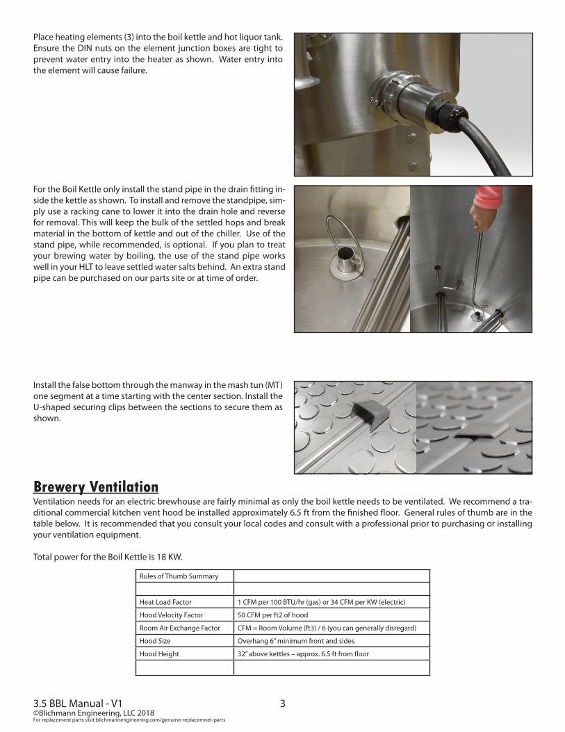
Place heating elements (3) into the boil kettle and hot liquor tank. Ensure the DIN nuts on the element junction boxes are tight to prevent water entry into the heater as shown. Water entry into the element will cause failure.
Install the false bottom through the manway in the mash tun (MT) one segment at a time starting with the center section. Install the U-shaped securing clips between the sections to secure them as shown.
For the Boil Kettle only install the stand pipe in the drain fitting in-side the kettle as shown. To install and remove the standpipe, sim-ply use a racking cane to lower it into the drain hole and reverse for removal. This will keep the bulk of the settled hops and break material in the bottom of kettle and out of the chiller. Use of the stand pipe, while recommended, is optional. If you plan to treat your brewing water by boiling, the use of the stand pipe works well in your HLT to leave settled water salts behind. An extra stand pipe can be purchased on our parts site or at time of order.
Brewery VentilationVentilation needs for an electric brewhouse are fairly minimal as only the boil kettle needs to be ventilated. We recommend a tra-ditional commercial kitchen vent hood be installed approximately 6.5 ft from the finished floor. General rules of thumb are in the table below. It is recommended that you consult your local codes and consult with a professional prior to purchasing or installing your ventilation equipment.
Total power for the Boil Kettle is 18 KW.
Rules of Thumb Summary
Heat Load Factor 1 CFM per 100 BTU/hr (gas) or 34 CFM per KW (electric)
Hood Velocity Factor 50 CFM per ft2 of hood
Room Air Exchange Factor CFM = Room Volume (ft3) / 6 (you can generally disregard)
Hood Size Overhang 6” minimum front and sides
Hood Height 32” above kettles – approx. 6.5 ft from floor
33.5 BBL Manual - V1©Blichmann Engineering, LLC 2018For replacement parts visit blichmannengineering.com/genuine-replacemnet-parts

Control Panel InstallationWarning: Always follow ALL local codes and regulations for installation of this panel. We highly recommend hiring a certified elec-trician for this work! This panel is designed for 240 VAC single phase power only. Contact us for 3 phase system options.
The back of the panel has 4 holes for affixing the panel to the wall of the brewhouse or onto a suitable stand. Mounting hardware or stand is not included. The image below indicates the locations of the main components. The drawing in the binder appendix shows the mounting dimensions for the panel.
Kettle TemperatureControllers (PID’s)
Heaters ON Indicator Lamps
Heater ControlSelector Switches
Heater Power Selector Switches
Timer Selector Switch
43.5 BBL Manual - V1©Blichmann Engineering, LLC 2018For replacement parts visit blichmannengineering.com/genuine-replacemnet-parts

DC Control Power Supply
Main GFI Breaker
Heating Element Breakers
Heating Element Contactors Heating Element Ground Bar
Main Power GFI Breaker – this industrial grade GFI (ground fault interrupting) breaker is the connection point for main power cables connected to the panel. Consult your local codes to determine if you can utilize this breaker as a main disconnect as well. In any case, we highly recommend a suitable disconnect switch be installed prior to the panel for safe servicing of the panel. Your contractor will need to punch a hole in your panel for the main power cable conduit in your desired location. Power demand for the brewhouse is 150A at 240V (single phase). Select a main breaker setting for 20% above the appropriate amperage to avoid nuisance tripping or as directed by your local codes.
RTD’s – the brewhouse is equipped with two durable high precision 100 ohm platinum RTD’s (resistance temperature detectors). Wire the sensors to the control panel terminal block shown in the image. The wiring diagram in the RTD junction box is also shown. Important: use shielded 3 conductor cable designed specifically for wiring RTD’s for most accurate readings. Automation Direct part number RTDW-50-02 (50 ft) or RTDW-100-02 (100 ft) are recommended and reasonably priced.
53.5 BBL Manual - V1©Blichmann Engineering, LLC 2018For replacement parts visit blichmannengineering.com/genuine-replacemnet-parts

Referencing the image below, place a jumper wire between terminal 1 and 2 on the inside of the RTD junction box (both red wires).
Connect the white wires both labeled (+) to the terminals in the control panel listed below. Note that the white wires are not polarity specific. Connect the red wire labeled terminal 1 to the control panel terminal listed below.
RTD Wiring Inside Control PanelBoil KettleBoth Reds to 1White to 2White to 3
Mash TunBoth Reds to 4White to 5White to 6
HLTBoth Reds to 7White to 8White to 9
Terminal 1(Red wire to panel)
Terminal 2
Install JumperWhite wires to
panel
Heating Elements: The brewhouse is supplied with six 6,000 W ultra-low watt density heating elements. Each heating element will draw 25A at 240V. Each element is pre-wired for 240V operation and has a pigtail with an L6-30P twist lock connector for easy removal for cleaning. We recommend SJOOW type cable 10 ga minimum. Again, your local codes will dictate the cable type and gauge.
IMPORTANT: Always consult your local codes to determine what type of cable is acceptable, what gauge is required, and maximum lengths of flexible cable allowed.
63.5 BBL Manual - V1©Blichmann Engineering, LLC 2018For replacement parts visit blichmannengineering.com/genuine-replacemnet-parts

IMPORTANT: The heating elements are pre-wired at the factory for 240V operation.
CAUTION – ensure the DIN nut on the heater junction box is tight to keep any water out of the box. NEVER immerse the junction box or cord in liquids!
7
Float Switches – float switches are provided to help prevent unintended energizing of the heating elements. It is vital that the heating elements be immersed in liquid prior to energizing them. Failure to immerse the heating elements will cause them to fail and potentially cause a fire! Wire from the float switch to the terminal block shown in the panel above. Wire to terminal 1 and 2 on the float switch. Polarity is not important. Use suitable 2 wire cable (18 ga recommended) for connection. If jumper wires are installed in the panel remove them when you install the switch wires.
When wiring the float switches to the control panel use a continuity tester on the leads to ensure that the switch is open when in the down (empty) position, and is closed (has continuity) in the up (full) position. At that time wire to the panel.
CAUTION: The low water level switches are a backup to an unintended energizing of the heaters. They are NOT intended to be normal shutoff switches and solely relied upon to keep the heaters from
unintentionally energizing! Dry-fired heating elements are not covered under warranty!
WARNING - DO NOT twist the float switch apart. This is NOT covered
under warranty.
The indent should be pointed up for proper float switch operation.
3.5 BBL Manual - V1©Blichmann Engineering, LLC 2018For replacement parts visit blichmannengineering.com/genuine-replacemnet-parts

8
Control Panel OperationReference the figures on pages 3 and 4 for locations of components.
PID’s – The PID controllers are pre-set for optimum heating rates and minimum overshoot. The corresponding large green lamp below the PID will indicate when the control is powering the heating elements. As the temperature approaches the set point the controller will automatically begin to cycle the heating elements on and off for a short period approximately every 30 seconds to maintain the set temperature. Typical stability is about +/- 1F. Note that the MASH PID is displaying temperature only and does not energize heating elements.
To change the set point press the UP/DOWN arrows until you reach your desired setting. Then press the enter button to accept this value.
Important: the value will flash until you press the enter button – if it is flashing the controller will NOT change to the newtemperature!
Heater Control Selector Switch – there are three positions for the power selector switch.
Energizes the corresponding heating elements at all times and is used as manual override. It bypasses the PID and the low water level float switch. It is used as an emergency override should a component fail during a brew day.
De-energizes the heating elements in all cases and prevents heater from energizing. Select this position as you begin to frain a tank or wish to prevent unitended powering of the heaters.
Allows the PID to automatically turn on the heaters to maintain the desired set temperature and allows the low level switches protect the heating elements from firing while dry.
ON -
OFF -
AUTO -
Heater Power Selector Switches – the heater selector switches are used to select the total power input to your kettle. Each switch controls 3 heating elements. You may select, for example, element 1 only (1/3 power), element 1-2 (2/3 power), or 1-2-3 (full power). This is particularly helpful during the boil to control the boil intensity.
Timer – a start delay timer is provided to allow you to start heating brewing liquor in advance of your brew day so that you have hot liquor available at the exact desired temperature upon arrival for brewing. The factory setting is 0-30 hr delay. To select other ranges, for example 0-10 hour, consult the timer manual for dip switch positions. Using the inner most scale, rotate the timer to the hours of delay. For example if it is currently 5 PM, and you wish for the controller to power up the HLT at 5 AM, set the dial to 12.
The timer selector switches are preset at the factory for a 30 hour range. See graphic below for switch positions.
1 2 3 4 5
UP X X X X
DOWN X
NOTE: there is approximately a 40 min safety delay before the timer will energize the heaters after starting the timer. Always set the timer for at least a one hour delay.
Timer Selector Switch – this switch has three positions:
Allows the timer to control the starting time for the selected heaters
If you choose to change the start time in the middle of a delay, move the dial on the timer and momentarily move the selector switch to RESET and then back to ON. This cycles power to the timer and starts the new timing se-quence.
Disables the timing function altogether. If you do not intend to use the timer, leave the selector switch in this position
ON-
RESET-
OFF-
3.5 BBL Manual - V1©Blichmann Engineering, LLC 2018For replacement parts visit blichmannengineering.com/genuine-replacemnet-parts
WARNING: Always ensure your tanks are full of water prior to turning the timer function ON and also ensure your PID selector switch in in the AUTO mode! Energizing the heaters dry will cause the heaters to fail and potentially cause a fire. Boiling water unattended (if heaters left in the ON position) will cause a similar failure if the water boils off.
WARNING: consult your local codes and regulations for unattended operation of your system.
Emergency Stop – this switch disables all heater contactors in the panel and also can be used for ensuring your heaters do not inadvertently power on. For safety, install a padlock through the hole in the switch to prevent unauthorized operation of the panel.
WARNING: pressing the emergency stop button does NOT cut power from the inside of the panel! All internal components will be live! To service the panel, disconnect main power to the panel before opening the panel.
Brewhouse OperationThe hybrid design combines the conveniences of a traditional brewhouse with the simplicity, familiarity, and lower start-up cost of a homebrew system. This allows a fast and easy transition into commercial brewing with very few sacrifices! As such, startup and the learning curve is quite simple. This system is a fly-sparge design and includes a boil kettle, a hot liquor tank, and a mash/lauter tun. Note that the boil kettle and HLT are identical kettles for convenience. Both contain a whirlpool port. For the HLT, simply cap the whirlpool port with the included fittings.
IMPORTANT: This manual is not intended as a brewing guide. If you are not intimately familiar with all grain brewing techniques we highly recommend the following texts from the Brewers Association:
How to Brew (Palmer)Water (Palmer & Kaminski)Yeast (Zainasheff and White)Malt (John Mallet)For the Love of Hops (Stan Hieronymus)Brewing Classic Beer Styles (Zainasheff & Palmer)
Heating Hot LiquorFor a typical brew day you will fill your HLT with enough water for your full brew length. Always better to have too much hot liquor than too little! For higher gravity beers it may be necessary to add more liquor to your HLT after dough-in. Or simply heat your strike water in your boil kettle, and separately heat your sparge water in your HLT. It is really a matter of preference.
TIP: For recipe calculation and strike water temps we have loaded the 3.5 BBL Hybrid kettles into BeerSmith. We highly recommend this software for all of your brews. It will take a few brews to dial in all of your parameters to achieve consistent results.
CAUTION: prior to powering up your panel, or pulling the emergency stop switch to the ON position, turn all heater control selector switches to OFF! This will prevent unintended energizing of the heating elements. ALWAYS be in the habit of turning the heater power selector switches to OFF prior to draining any kettle!Fill your HLT and (and/or boil kettle) with the desired amount of water ensuring that there is enough water to actuate the float switches. If the switches are not floating they will not allow the heaters to energize!
Set your strike water to the desired temperature. Remember to press the enter key to accept the new value. If the screen is flashing the new setting has NOT been accepted.
MashingWhen the temperature has been reached and you are ready to pump liquor to the MT turn the PID selector switch to OFF. Underlet water into the MT by pumping water from the HLT into the BOTTOM of the MT. When you have 3-4” of water above the false bottom begin adding and stirring the malt as you continue to pump.
TIP: we recommend underletting so that the malt and water combine and reach close to your desired rest temperature at all times. It takes 15-20 min to stir in all the malt and conversion does begin quickly. If you were to fill the MT with all the hot liquor and then add the malt you would over-shoot your infusion temperature for the first 15-20 minutes until you had all the malt in the MT. Therefore underletting is highly advised. Having one person stir while another adds malt is very helpful.
93.5 BBL Manual - V1©Blichmann Engineering, LLC 2018For replacement parts visit blichmannengineering.com/genuine-replacemnet-parts

Your mash tun, even though uninsulated, will lose less than 1 F/hr. Rarely do commercial breweries perform step mashing. Modern malts are highly modified and very little is to be gained by step mashing. Homebrew kettles, on the other hand, are so small that they lose heat quickly so temperature maintenance is common (RIMS/HERMS).
After your scarification rest period, vorlauf (recirculate) your wort for about 10 minutes to clarify the wort and set the grain bed in preparation for runoff to the BK. Now is a good time to check that you have your stand pipe installed in your boil kettle as detailed previously.
Lautering (sparging) and vorlauf are both performed using the CIP ball included with the system to gently distribute liquor or wort over the top of the grain bed. See the image below. Take care to avoid too fast of a runoff which may stick the mash. Note that the level gauge also acts as a manometer that measures the suction pressure on the grain bed. If the level in the gauge is more than 1/3 lower than the level in the tank you are drawing too quickly and will soon stick your mash. In general, you want to lauter your mash for 45 -60 min for optimum efficiency. Stop runoff when your runnings are below 1.010 SG (2.5 deg Plato) or when your runnings reach 6 pH.
IMPORTANT: Do NOT sparge or vorlauf at full pump flow or you are very likely to stick your mash, and your efficiency will suffer severely!
TIP: Your pumps are equipped with sanitary diaphragm valves that make easy work of balancing your flow rates. After a few brews you will determine the number of turns on the valve to achieve your desired flow. Simply make the same number of turns on each pump and your flows will be very close to balanced.
TIP: Raking (stirring) the top 1/3 of the mash every 15 minutes during lautering helps to remove any preferential flow paths and provides a more efficient uniform lauter.Boiling:
Once the level of the wort in your BK / HLT has reached your float switch, turn the corresponding heater control selector switch to AUTO and adjust the set point on the PID to 220F to achieve a boil. That will fire the elements continuously.
CAUTION: if you turn your heater control selector switch to ON when boiling, your float switches are bypassed and will NOT protect your heating elements should you inadvertently drain the BK with the elements energized! Dry fired heating elements that fail are not covered under warranty!
TIP: If the boil is too aggressive use the heater selector switch to de-energize one of the heating elements. Note that a proper boil is between a simmer and a surging boil. Shoot for a 3-5% boil off rate per hour.
IMPORTANT: To drive off DMS ALWAYS boil with the lid open!
After your boil is complete turn your heater power selector switch to the OFF position. You can either whirlpool manually with the stir paddle or connect the pump to the system and recirculate through the tangential port on the side of the kettle. Either method provides a suitable whirlpool. Note that a slow rotation is really all that’s needed. After whirlpool, close the lid and allow 15-20 min-utes for the convection currents to slow and the hop and trub to settle to the bottom center of the kettle.
103.5 BBL Manual - V1©Blichmann Engineering, LLC 2018For replacement parts visit blichmannengineering.com/genuine-replacemnet-parts

Chillers:
Sanitize the chiller by either pumping StarSan or similar copper friendly sanitizer through the chiller. Alternately the chiller may be submerged (fittings up) into a pail of sanitizer. Drain the chiller after the recommended time with the fittings facing down. Connect the chiller per the instructions on the nameplate. Cooling performance and other information is in the appendix.
Drain off the first gallon or so of wort from the boil kettle to a waste drain to eject any solids in the piping and to ensure only clear wort flows through the chiller to prevent plugging. Then divert the flow to the chiller. Adjust the wort flow and/or the cooling water flow to achieve the desired wort temperature to your fermentor.
IMMEDIATELY after use back-flush the chiller with hot water to eject any solids and wort. IMMEDIATELY soak the chiller fittings up in PBW or other copper friendly cleaning agents for 30 min or pump through the chiller. Rinse with hot water and then soak in sanitizer. Allow to drain fittings down, and then store with the chiller horizontal. Following this procedure consistently will give you a very long service life for your chiller.
Pumps: The pumps included with the system are seal-less magnetic drive pumps. They MUST NOT be run dry or the impeller bear-ing surface will be damaged! This is NOT covered under warranty. Ensure the hoses and pump head are filled with liquid before turning on the pump. If you hear a loud squeal stop the pump immediately!
Caution: NEVER restrict the inlet to the pump. Always place flow throttling valves on the OUTLET of the pump ONLY. Failure to do this will cause cavitation in the pump possibly leading to failure of the impeller. If you hear any grumbling or grinding in the pump STOP IMMEDIATELY as this is cavitation. Cavitation failures are NOT covered under warranty.
Tip: A spray of StarSan on the interior surfaces after cleaning will help prevent mildew between uses.
Tip: Place your chiller in-line with the pump to clean it at the same time.
Mash tun: Spent grains can easily be removed through the manway in the mash tun. Drain all remaining wort out of the bottom drain and then open the door. Utilizing a non-marring hoe (available in our maintenance kit) rake out the spent grains into a tub, also available through Blichmann Engineering. Remove the false bottom sections and spray them off with hot water and allow to dry. Spray excess grain from the sidewalls and bottom of the kettles with a hose.
HLT/BK/MT: Due to the easy access through the top of the relatively small tanks, and small size of the chiller and pumps, it is usually fastest to scour the kettles with a scrub brush mounted on a pole and spray them out with a hose. Optional cleaning tools (appendix in the manual) are available through Blichmann Engineering to make this a fast and thorough job. Alternately, you can utilize one of the heated vessels to heat and hold your CIP (clean in place) chemicals and use one pumps to recirculate through the CIP ball and the second pump to return back into the chemical kettle. It is recommended that you turn off all heaters while running the CIP system to avoid dry firing them. Tip your kettles forward so that all water drains out the bottom valve, leave the lid open, and allow the kettles to dry thoroughly.
Cleaning Your System:
Typical heating rates are 1-1.5 F/min. Expect about a 5% boil-off rateStrike water will cool about 10F when pumped from the HLT to the MTTemperature loss in MT – less than 1F/hrTemperature stability of control system approximately +/- 1 F
Heating Elements: It is easiest to clean your heating elements by removing them from your kettles and soaking them in a pail of hot PBW. After an hour soak scrub them with a brush and rinse with hot water. If you are noticing a scale form on them over time, an acid soak will generally dissolve the water salts.
WARNING: ALWAYS Remove the power supply cable from the heating element pig-tail before removal! If the heaters inadvertently energize they get extremely hot and will cause extreme burns and possibly a fire! NEVER soak the DIN connection junction box or power cable in liquids. ONLY THE HEATING TUBES! Any liquids inside of the junction box can cause immediate failure of the element and/or the control panel!
Helpful System Data
113.5 BBL Manual - V1©Blichmann Engineering, LLC 2018For replacement parts visit blichmannengineering.com/genuine-replacemnet-parts

Blichmann Engineering Product WarrantyA. Limited Warranty 1. Blichmann Engineering warrants to the original purchaser that this product will be free from manufacturing defects in material and workmanship for a period of one (1) year from the date of purchase by the customer. Proof of purchase is required. Blichmann Engineering’s obligation to repair or replace defective materials or workmanship is the sole obligation of Blichmann Engineering under this limited warranty. 2. The limited warranty covers only those defects that arise as a result of normal use of the product and does not cover any other problems, including, but not limited to, those that arise as a result of: a. Improper maintenance or modification; b. Damage due to incorrect voltage or improper wiring by customer; c. Operation outside of the product’s specifications; d. Carelessness or neglect to operate the product in accordance with instructions provided with the product; e. Damaging the tamper label on the product; f. Damage by over-tightening the fasteners; g. Failure to follow cleaning and / or maintenance procedures; or h. Exceeding published operational temperatures. 3. Blichmann Engineering reserves the right to request delivery of the defective component for inspection before processing the warranty claim. If Blichmann Engineering receives, during the applicable warranty period, notice of a defect in any component that is covered by the warranty, Blichmann Engineering shall either repair or replace the defective component with a new or rebuilt component at Blichmann Engineering’s option. 4. Blichmann Engineering must be notified within seven (7) days of the delivery date of any shipping damage. Customer is responsible for shipping damage outside of this time period. Approval for return must be provided by Blichmann Engineering prior to any return. Customer is responsible for keeping all original packaging material for warranty returns. Blichmann Engineering is not responsible for damage from improperly packaged warranty returns, and these repair costs will be the sole responsibility of the customer. Shipping costs for warranty returns are covered only for the contiguous United States. 5. Blichmann Engineering’s limited warranty is valid in any country where the product is distributed. ________________________________________B. Limitations of Warranty 1. Any implied warranty that is found to arise by way of state or federal law, including any implied warranty of merchantability or any implied warranty of fitness, is limited in duration to the terms of this limited warranty and is limited in scope of coverage to this warranty. Blichmann Engineering disclaims any express or implied warranty, including any implied warranty of fitness for a particular purpose or merchantability, on items excluded from coverage as set forth in this limited warranty. 2. Blichmann Engineering makes no warranty of any nature beyond that contained in this limited warranty. No one has authority to enlarge, amend, or modify this limited warranty, and Blichmann Engineering does not authorize anyone to create any other obligation for it regarding this product. 3. Blichmann Engineering is not responsible for any representation, promise, or warranty made by any independent dealer or other person beyond what is expressly stated in this limited warranty. Any selling or servicing dealer is not Blichmann Engineering’s agent, but an independent entity.________________________________________C. Limitations of Liability 1. The remedies provided in this warranty are the customer’s sole and exclusive remedies. 2. Except for the obligations specifically set forth in this warranty, in no event shall Blichmann Engineering be liable for direct, indirect, special, incidental, or consequential damages, whether based on contract, tort, or any other legal theory and whether or not advised of the possibility of such damages. 3. This warranty does not cover, and in no event shall Blichmann Engineering be liable for, travel, lodging, or any other expense incurred due to manufacturing defects in material and workmanship, or any other reason. 4. Any performance of repairs after the warranty coverage period has expired or performance of repairs regarding anything excluded from coverage after this limited warranty shall be considered good-will repairs and they will not alter the terms of this limited warranty, or extend any warranty coverage period. 5. Venue for any legal proceedings relating to or arising out of this warranty shall be in Tippecanoe County, Indiana, United States, which courts will have exclusive jurisdiction.________________________________________D. Local Law 1. This warranty gives the customer specific legal rights. The customer may also have other rights that vary from state to state in the United States or other countries. 2. To the extent that this warranty is inconsistent with local law, it shall be deemed modified, only to the extent necessary to be consistent with such local law.
123.5 BBL Manual - V1©Blichmann Engineering, LLC 2018For replacement parts visit blichmannengineering.com/genuine-replacemnet-parts