35 &7&03,8* & 03’* - megah tri...
TRANSCRIPT

COPYRIGHT HYUNDAI VALVE IND. CO., LTD ALL RIGHT RESERVED
OFFICE ADDRESS: 10F Doosan Venture Digm, Pyeongchon-dong, Dongan-gu Anyang-si, Gyeonggi-do, KoreaTEL: 82-478-4015/16 FAX: 82-31-478-4017
FACTORY HWASEONG FACTORY: 209-9, GOJU-RI, PALTAN-MYEON, HWASEONG-SI, GYEONGGI-DO, KOREAGIMHAE FACTORY: 498, SHINCHEON-RI, HALLIM-MYEON, GIMHAE-SI, GYEONGHAM, KOREA
WEBSITE www.hyundaivalve.com
Forged Steel CatalogueCheck, Gate, Globe
page 2
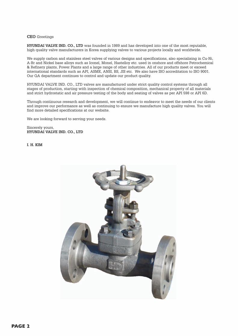
CEO Greetings
HYUNDAI VALVE IND. CO., LTD was founded in 1989 and has developed into one of the most reputable,high quality valve manufacturers in Korea supplying valves to various projects locally and worldwide.
We supply carbon and stainless steel valves of various designs and specifications, also specialising in Cu-Ni,A-Br and Nickel base alloys such as Iconel, Monel, Hastelloy etc. used in onshore and offshore Petrochemical& Refinery plants, Power Plants and a large range of other industries. All of our products meet or exceedinternational standards such as API, ASME, ANSI, BS, JIS etc. We also have ISO accreditation to ISO 9001.Our QA department continues to control and update our product quality.
HYUNDAI VALVE IND. CO., LTD valves are manufactured under strict quality control systems through allstages of production, starting with inspection of chemical composition, mechanical property of all materialsand strict hydrostatic and air pressure testing of the body and seating of valves as per API 598 or API 6D.
Through continuous research and development, we will continue to endeavor to meet the needs of our clientsand improve our performance as well as continuing to ensure we manufacture high quality valves. You willfind more detailed specifications at our website.
We are looking forward to serving your needs.
Sincerely yours,HYUNDAI VALVE IND. CO., LTD
I. H. KIM

page 3
Index
Model Number System
Material Options
Screwed and Weld End Check, Gate, Globe
Flanged Check, Gate, Globe
ISO9001 Certificate
Page 4
Page 5
Page 6-20
Page 21-26
Page 27

page 4
VA
LV
E T
YP
E
SIZ
E
TR
IM
MA
TE
RIA
LS
HE
LL
MA
TE
RIA
L
3
54
1
12
34
56
78
BC
=B
all
Check
BL
=B
ello
ws S
eate
d
GA
=G
ate
Valv
e
GL
=G
lobe V
alv
e
SC
=S
win
g C
heck V
alv
e
LC
=Lift
Check V
alv
e
AN
=A
ngle
Valv
e
YG
=Y
-Glo
be V
alv
e
XX
=S
pecia
l
No A B C D E F G H I J K Z
GA
A2
H0
2A
FL
N
A=
Bolted B
onnet
(FB
)
B=
Bolted B
onnet
(RB
)
C=
Weld
ed B
onnet
(FB
)
D=
Weld
ed B
onnet
(RB
)
E=
Pre
ssure
Seal B
onnet
(FB
)
F=
Pre
ssure
Seal B
onnet
(RB
)
X=
Specia
l
Seat
ing
Surf
aces
Dis
cSe
at
13C
r13C
r
HF
13C
r
HF
HF
304SS
304SS
HF
304SS
HF
HF
316SS
316SS
HF
316SS
HF
HF
Monel
Monel
Allo
y 20
Allo
y 20
Speci
alSp
eci
al
A=
1/4
”
B=
3/8
”
C=
1/2
”
D=
3/4
”
E=
1”
F=
1-1
/4”
G=
1-1
/2”
H=
2”
I=
2-1
/2”
J=
3”
K=
4”
L=
5”
M=
6”
N=
8”
O=
10”
P=
12”
Q=
14”
R=
16”
S=
18”
T=
20”
U=
22”
V=
24”
W=
26”
X=
28”
Y=
30”
Z=
Speci
al
01
=A
105(N
)
02
=A
216-W
CB
03
=A
351-C
F3
04
=A
351-C
F3M
05
=A
351-C
F8
06
=A
351-C
F8M
07
=A
351-C
N7M
08
=A
351-C
D4M
Cu
09
=A
352-L
CB
10
=A
352-L
CC
11
=A
351-L
F2
12
=A
350-L
F3
13
=A
182-F
304
14
=A
182-F
304L
15
=A
182-F
316
16
=A
182-F
316L
17
=A
182-F
5a
18
=A
182-F
9
19
=A
182-F
11
20
=A
182-F
22
21
=A
182-F
51
22
=A
182-F
53
23
=A
182-F
91
24
=A
494-C
W12M
W
25
=B
148
26
=B
160
27
=B
164
28
=B
166
29
=B
335
30
=B
337
31
=B
338
32
=B
363
33
=B
367
34
=B
381
35
=B
446
36
=B
564
37
=B
574
38
=B
584
99
=S
pecia
l
6
EN
D C
ON
NE
CT
IO
N6 B
=B
utt
weld
F=
Flan
ged R
F
R=
Flan
ged R
TJ
S=
Sock
et W
eld
T=
Thre
ad
U=
Uncu
t RT
J
X=
Speci
al
Stem
13C
r
13C
r
13C
r
304SS
304SS
304SS
316SS
316SS
316SS
Monel
Allo
y 20
Speci
al
PR
ES
SU
RE
CL
AS
S2 1
=150#
2=
300#
3=
600#
4=
800#
5=
900#
6=
1500#
7=
2500#
A=
10K
B=
16K
C=
20K
D=
30K
E=
40K
F=
63K
G=
100K
Z=
Speci
al
OT
HE
RS
7 E=
Ele
ctr
ic O
pe
rate
d
G=
Ge
ar
Op
era
ted
L=
Ha
nd
wh
ee
l O
pe
rate
d
P=
Pn
eu
ma
tic O
pe
rate
d
N=
No
t A
pp
lica
ble
SP
EC
IA
L8 N
=N
AC
E
Bla
nk
=
No
n N
AC
E
Model Number System

page 5
Material Options
PART DESCRIPTION
CARBON STEEL
LOW-TEMPCARBON STEEL
Cr-Mo ALLOY STEEL
STAINLESS STEEL
SPECIAL ALLOYS
BODYBONNETCOVER
A105N A350/LF2 A182/F1A182/F5A182/F9A182/F11A182/F22
A182/F304A182/304LA182/F316A182/F316LA182/F317A182/F317LA182/F321A182/F347
HastelloyInconelMonelDuplex
STEMSEAT RING*
A276/CA15A276/304A276/316
A276/410A276/304A276/316
A276/410A276/304A276/316
A276/304A276/316A276/321A276/317A276/347
HastelloyInconelMonelDuplex
WEDGE / DISC* A217/CA15A351/CF8A351/CF8M
A217/CA15A351/CF8A351/CF8M
A217/CA15A351/CF8A351/CF8M
A351/CF8A351/CF8M
A351/CG8M
A351/CF8C
HastelloyInconel
MonelDuplex
YOKE SLEEVE BUSH A582-416 A582-416 A582-416 A582-416 A582-416
GLAND FLANGE A105N A105N A105N A182/F304 A182/F304
GLAND PACKING Graphite Graphite Graphite Graphite Graphite
BONNET BOLT A193/B7 A320/L7 A193/B16 A193/B8M A193/B8M
GLAND BOLT A193/B8 A193/B8 A193/B16 A193/B8M A193/B8M
GLAND NUT A194/2H A194/2H A194/2H A194/8 A194/8
GLAND A276/410 A276/410 A276/410 A276/304 A276/304
HANDWHEEL Carbon Steel Carbon Steel Carbon Steel Carbon Steel Carbon Steel
GASKET A204/304+GraphiteA240/316+Graphite
A204/304+GraphiteA240/316+Graphite
A204/304+GraphiteA240/316+Graphite
A204/304+GraphiteA240/316+Graphite
A204/304+GraphiteA240/316+Graphite
HANDWHEEL NUT Carbon Steel Carbon Steel Carbon Steel Carbon Steel Carbon Steel
NAME PLATE Aluminium Aluminium Aluminium A240/304 A240/304
* + STELLITE #6 OPTIONAL
PaGE 6
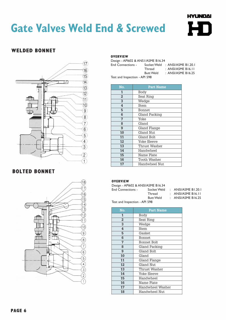
Gate Valves Weld End & Screwed
BOLTED BONNET
OVERVIEW
Design - API602 & ANSI/ASME B16.34
End Connections - Socket Weld : ANSI/ASME B1.20.1
Thread : ANSI/ASME B16.11
Butt Weld : ANSI/ASME B16.25
Test and Inspection - API 598
WELDED BONNETOVERVIEW
Design - API602 & ANS1/ASME B16.34
End Connections - Socket Weld : ANSI/ASME B1.20.1
Thread : ANSI/ASME B16.11
Butt Weld : ANSI/ASME B16.25
Test and Inspection - API 598
No. Part Name1 Body2 Seat Ring3 Wedge4 Stem5 Gasket6 Bonnet7 Bonnet Bolt8 Gland Packing9 Gland Bolt10 Gland11 Gland Flange12 Gland Nut13 Thrust Washer14 Yoke Sleeve15 Handwheel16 Name Plate17 Handwheel Washer18 Handwheel Nut
No. Part Name1 Body2 Seat Ring3 Wedge4 Stem5 Bonnet6 Gland Packing7 Yoke8 Gland9 Gland Flange10 Gland Nut11 Gland Bolt12 Yoke Sleeve13 Thrust Washer14 Handwheel15 Name Plate16 Tooth Washer17 Handwheel Nut

page 7
Gate Valve Bellow Sealed Weld End & Screwed
BOLTED BONNET OVERVIEW
Design - API602, BS 5352, MSS SP 1, ANSI/ASME B16.34
End Connections - Socket Weld : ANSI/ASME B16.11
Thread : ANSI/ASME B1.20.1
Butt Weld : ANSI/ASME B16.25
Flange : ANSI/ASME B16.5
Test and Inspection - API 598 / BS 5146
No. Part Name1 Body2 Wedge3 Seat Ring4 Gasket5 Bellows Holder Lower6 Bonnet Bolt7 Bellows8 Stem9 Bonnet10 Bonnet Upper11 Gland Packing12 Yoke13 Gland14 Gland Flange15 Gland Nut16 Gland Bolt17 Thrust Washer18 Yoke Sleeve19 Handwheel20 Handwheel Washer21 Name Plate22 Handwheel Nut

page 8
DimensionsGate Valves Weld End & Screwed
WELDED & BONNET BOLTED aNSI CLaSS 800
WELDED & BONNET BOLTED aNSI CLaSS 2500
WELDED & BONNET BOLTED aNSI CLaSS 1500
Regular Port Size (in) 1⁄4 3⁄8 1⁄2 3⁄4 1 11⁄4 11⁄2 2
Full Port Size (in) 1⁄4 3⁄8 1⁄2 3⁄4 1 11⁄4 11⁄2
L (mm/in) 79 3.11 79 3.11 79 3.11 92 3.62 111 4.37 120 4.72 120 4.72 140 5.51
W (mm/in) 84 3.3 84 3.3 84 3.3 97 3.82 97 3.82 137 5.39 137 5.39 157 6.18
H (mm/in) 144 5.67 144 5.67 144 5.67 154 6.06 177 6.97 225 8.86 225 8.86 254 10.0
P (mm/in) 6.4 0.25 9.5 0.38 9.5 0.38 12.5 0.5 18.5 0.73 23.5 0.93 23.5 0.93 36 1.41
Wt (kgs/lbs) 1.5 3.31 1.5 3.31 1.5 3.31 2.2 4.9 2.8 6.4 5.60 12.35 5.60 12.35 8.5 18.74
Cv Factor 1.0 2.0 2.0 3.0 5.5 11.5 17.0 21.0
Valve Size (in) 1⁄2 3⁄4 1 11⁄4 11⁄2 2
L (mm/in) 111 4.37 111 4.37 120 4.72 140 5.51 140 5.51 1.78 7.01
W (mm/in) 140 5.5 160 6.25 200 7.88 230 9.07 230 9.07 250 9.82
H (mm/in) 224 7.88 253 9.94 317 12.5 337 14.88 377 14.88 458 18.0
P (mm/in) 11 0.44 20 0.63 20 0.82 26 1.07 32 1.25 43 1.69
Wt (kgs/lbs) 5.0 11.0 7.0 15.4 10.0 22.0 18.2 40.1 18.0 39.7 30.0 66.1
Full Port Cv Factor 2.6 6.0 2.0 11.3 26.3 52.4
Valve Size (in) 1⁄2 3⁄4 1 11⁄4 11⁄2 2
L (mm/in) 127 5 155 6.102 210 8.267 229 9.015 229 9.015 235 9.251
W (mm/in) 160 6.299 200 7.874 230 9.055 250 9.84 250 9.84 300 11.81
H (mm/in) 253 9.96 317 12.48 377 14.84 458 18.03 458 18.03 470 18.5
P (mm/in) 11 0.433 16 0.629 20 0.787 26 1.023 28.5 1.122 38.1 1.69
Wt (kgs/lbs) 8.0 17.6 11.0 24.2 19.0 41.8 34.0 74.8 32.0 70.4 45.0 99.0
Full Port Cv Factor 10.5 22.5 28.3 68.2 78.5 21.0

page 9
Globe Valves Weld End & Screwed
BOLTED BONNET
WELDED BONNET
No. Part Name1 Body2 Seat Ring3 Wedge4 Stem5 Gasket6 Bonnet7 Bonnet Bolt8 Gland Packing9 Gland Bolt10 Gland11 Gland Flange12 Gland Nut13 Thrust Washer14 Yoke Sleeve15 Handwheel16 Name Plate17 Handwheel Washer18 Handwheel Nut
No. Part Name1 Body2 Seat Ring3 Wedge4 Stem5 Bonnet6 Gland Packing7 Yoke8 Gland9 Gland Flange10 Gland Nut11 Gland Bolt12 Yoke Sleeve13 Thrust Washer14 Handwheel15 Name Plate16 Tooth Washer17 Handwheel Nut
OVERVIEW
Design - API602, BS5352 & ANSI/ASME B16.34
End Connections - Socket Weld : ANSI/ASME B1.20.1
Thread : ANSI/ASME B16.11
Butt Weld : ANSI/ASME B16.25
Test and Inspection - API 598 / BS5146
OVERVIEW
Design - API602, BS5352 & ANS1/ASME B16.34
End Connections - Socket Weld : ANSI/ASME B1.20.1
Thread : ANSI/ASME B16.11
Butt Weld : ANSI/ASME B16.25
Test and Inspection - API 598 / BS5146

page 10
Globe Valve Bellow Sealed Weld End & Screwed
BOLTED BONNET OVERVIEW
Design - API602, BS 5352, MSS SP 11, ANSI/ASME B16.34
End Connections - Socket Weld : ANSI/ASME B16.11
Thread : ANSI/ASME B1.20.1
Butt Weld : ANSI/ASME B16.25
Flange : ANSI/ASME B16.5
Test and Inspection - API 598 / BS 5146
No. Part Name1 Body2 Disc3 Split Ring4 Disc Nut5 Gasket6 Bellows Holder Lower7 Bonnet Bolt8 Bellows9 Stem10 Bonnet11 Bonnet Upper12 Guide Pin13 Gland Packing14 Yoke15 Gland16 Gland Flange17 Gland Nut18 Gland Bolt19 Thrust Washer20 Yoke Sleeve21 Handwheel22 Handwheel Washer23 Name Plate24 Handwheel Nut

page 11
DimensionsGlobe Valves Weld End & Screwed
WELDED & BOLTED BONNET aNSI CLaSS 1500
WELDED & BOLTED BONNET CLaSS 2500
WELDED & BOLTED BONNET aNSI CLaSS 800
Regular Port Size (in) 1⁄4 3⁄8 1⁄2 3⁄4 1 11⁄4 11⁄2 2
Full Port Size (in) 1⁄4 3⁄8 1⁄2 3⁄4 1 11⁄4 11⁄2
L (mm/in) 76 3.0 76 3.0 79 3.11 92 3.62 111 4.37 140 5.51 120 4.72 140 5.51
W (mm/in) 84 3.3 84 3.3 84 3.3 97 3.82 97 3.82 137 5.39 137 5.39 157 6.18
H (mm/in) 144 5.67 144 5.67 144 5.67 154 6.06 177 6.97 225 8.86 225 8.86 254 10.0
P (mm/in) 6.4 0.25 9.5 0.38 9.5 0.38 12.5 0.5 18.5 0.73 23.5 0.93 23.5 0.93 36 1.41
Wt (kgs/lbs) 1.5 3.31 1.5 3.31 1.5 3.31 2.2 4.9 2.8 6.4 5.60 12.35 5.60 12.35 8.5 18.74
Cv Factor 1.0 2.0 2.0 3.0 5.5 11.5 17.0 21.0
Valve Size (in) 1⁄2 3⁄4 1 11⁄4 11⁄2 2
L (mm/in) 111 4.37 111 4.37 120 4.72 172 6.77 172 6.77 200 7.87
W (mm/in) 140 5.5 160 6.25 200 7.88 230 9.07 230 9.07 250 9.82
H (mm/in) 230 9.03 261 10.25 314 12.38 377 14.88 377 14.88 459 18.1
P (mm/in) 12 0.44 16 0.63 20 0.82 26 1.07 26 1.07 43 1.69
Wt (kgs/lbs) 5.0 11.0 6.0 13.2 8.0 17.6 15.0 33.1 15.0 33.1 26.0 57.3
Full Port Cv Factor 2.8 3.2 6.8 15.2 19.6 27.0
Valve Size (in) 1⁄2 3⁄4 1 11⁄4 11⁄2 2
L (mm/in) 127 5 155 6.102 210 8.267 229 9.015 229 9.015 235 9.251
W (mm/in) 160 6.299 200 7.874 230 9.055 250 9.842 250 9.842 300 11.81
H (mm/in) 261 10.275 314 12.362 377 14.842 459 18.07 459 18.07 470 18.5
P (mm/in) 11 0.433 13 0.51 18 0.708 23 0.905 26 1.023 35 1.377
Wt (kgs/lbs) 8 17.6 10 22 17 37.4 28 61.6 28.0 61.6 43 94.6
Full Port Cv Factor 2.1 2.9 5.9 13.6 15.2 21.0

page 12
Y-Globe Valves Weld End & Screwed
BOLTED BONNET
WELDED BONNET
No. Part Name1 Body2 Disc3 Stem4 Gasket5 Bonnet6 Bonnet Bolt7 Gland Packing8 Gland Bolt9 Gland10 Gland Flange11 Gland Nut12 Yoke Bush13 Handwheel14 Name Plate15 Handwheel Washer16 Handwheel Nut
No. Part Name1 Body2 Seat3 Pad4 Disc5 Stem6 Disc Nut7 Bonnet8 Gland Packing9 Yoke10 Gland11 Gland Flange12 Gland Nut13 Gland Bolt14 Yoke Bush15 Handwheel16 Name Plate17 Tooth Washer18 Handwheel Nut
FEATURESDesign - API602, BS5352 & ANSI/ASME B16.34End Connections - Socket Weld : ANSI/ASME B1.20.1
Thread : ANSI/ASME B16.1Butt Weld : ANSI/ASME B16.25
Test and Inspection - API 598 / BS5146
OVERVIEW
Design - API602, BS5352 & ANS1/ASME B16.34
End Connections - Socket Weld : ANSI/ASME B1.20.1
Thread : ANSI/ASME B16.11
Butt Weld : ANSI/ASME B16.25
Test and Inspection - API 598 / BS5146

page 13
DimensionsY-Globe Valves Weld End & Screwed
BOLTED BONNET aNSI CLaSS 800
CLaSS 800 STaNDaRD BORE, OS&Y, SW, NPT, BW
WELDED BONNET aNSI CLaSS 800
Std Port Size (in) 1⁄4 3⁄8 1⁄2 3⁄4 1 11⁄4 11⁄2 2
Full Port Size (in) 1⁄4 3⁄8 1⁄2 3⁄4 1 11⁄4 11⁄2
L (mm/in) 76 3.0 76 3.0 76 3.0 92 3.62 104 4.02 124 4.89 124 4.89 152 5.99
W (mm/in) 84 3.3 84 3.3 84 3.3 97 3.82 97 3.82 137 5.39 137 5.39 157 6.18
H (mm/in) 167 6.58 167 6.58 167 6.58 180 7.09 207 8.15 225 10.04 225 10.04 300 11.82
P (mm/in) 6.4 0.25 9.5 0.38 9.5 0.38 12.5 0.5 18.5 0.73 23.5 0.93 30.5 1.20 36.0 1.41
Wt (kgs/lbs) 1.8 3.97 1.8 3.97 1.8 3.97 2.1 4.83 3.5 7.72 6.70 14.8 6.70 14.8 9.7 21.4
Cv Factor 4.5 6.0 6.0 14.0 19.5 27.0 32.5 40.0
Std Port Size (in) 1⁄4 3⁄8 1⁄2 3⁄4 1 11⁄4 11⁄2 2
Full Port Size (in) 1⁄4 3⁄8 1⁄2 3⁄4 1 11⁄4 11⁄2
L (mm/in) 76 3.0 76 3.0 76 3.0 92 3.55 102 4.02 124 4.89 124 4.89 152 5.99
W (mm/in) 84 3.3 84 3.3 84 3.3 97 3.82 97 3.82 137 5.39 137 5.39 157 6.18
H (mm/in) 167 6.58 167 6.58 167 6.58 180 7.09 207 8.15 225 10.04 225 10.04 300 11.82
P (mm/in) 6.4 0.25 9.5 0.38 9.5 0.38 12.5 0.5 18.5 0.73 23.5 0.93 30.5 1.20 36.0 1.41
Wt (kgs/lbs) 1.6 3.53 1.6 3.53 1.6 3.53 1.9 4.2 3.2 7.1 6.4 14.1 6.4 14.1 9.3 20.5
Cv Factor 4.5 6.0 6.0 14.0 19.5 27.0 32.5 40.0

page 14
DimensionsY-Globe Valves Weld End & Screwed
BOLTED BONNET aNSI CLaSS 1500
CLaSS 1500 STaNDaRD BORE, OS&Y, SW, NPT, BW
WELDED BONNET aNSI CLaSS 1500
Std Port Size (in) 1⁄4 3⁄8 1⁄2 3⁄4 1 11⁄4 11⁄2 2
Full Port Size (in) 1⁄4 3⁄8 1⁄2 3⁄4 1 11⁄4 11⁄2
L (mm/in) 90 3.6 90 3.6 90 3.6 102 4.02 124 4.89 152 5.99 152 5.99 200 7.87
W (mm/in) 97 3.82 97 3.82 97 3.82 97 3.82 137 5.39 157 6.18 157 6.18 157 6.18
H (mm/in) 180 7.09 180 7.09 180 7.09 207 8.15 255 10.04 300 11.82 300 11.82 355 14.0
P (mm/in) 6.4 0.38 9.5 0.38 9.5 0.38 3.6 7.94 6.8 15.0 9.8 21.6 9.8 21.6 14.3 31.5
Wt (kgs/lbs) 2.2 4.85 2.2 4.85 2.1 4.63 3.6 7.94 6.8 15.0 9.8 21.6 9.8 21.6 14.3 31.5
Cv Factor 4.5 6.0 6.0 14.0 19.5 27.0 32.5 40.0
Std Port Size (in) 1⁄4 3⁄8 1⁄2 3⁄4 1 11⁄4 11⁄2 2
Full Port Size (in) 1⁄4 3⁄8 1⁄2 3⁄4 1 11⁄4 11⁄2
L (mm/in) 90 3.55 90 3.55 90 3.55 102 4.02 124 4.89 152 5.99 152 5.99 200 7.87
W (mm/in) 97 3.82 97 3.82 97 3.82 97 3.82 137 5.39 157 6.18 157 6.18 157 6.18
H (mm/in) 180 7.09 180 7.09 180 7.09 207 8.15 255 10.04 300 11.82 300 11.82 355 14.0
P (mm/in) 6.4 0.38 9.5 0.38 9.5 0.38 12.5 0.5 18.5 0.73 23.5 0.93 30.5 1.2 36.0 1.41
Wt (kgs/lbs) 2.0 4.41 2.0 4.41 1.9 4.2 3.4 7.5 6.6 14.6 9.6 21.2 9.6 21.2 14.1 31.1
Cv Factor 4.5 6.0 6.0 14.0 19.5 27.0 32.5 40.0

page 15
DimensionsY-Globe Valves Weld End & Screwed
CLaSS 2500 STaNDaRD BORE, OS&Y, SW, NPT, BW
WELDED & BOLTED BONNET aNSI CLaSS 2500
Valve Size (in) 1⁄2 3⁄4 1 11⁄4 11⁄2 2
L (mm/in) 115 4.53 130 5.12 150 5.91 220 8.66 220 8.66 260 10.24
W (mm/in) 97 3.82 97 3.82 137 5.39 157 6.18 157 6.18 157 6.18
H (mm/in) 232 9.13 274 10.79 320 12.60 461 18.15 461 18.15 504 19.85
P (mm/in) 9.5 0.38 12.5 0.5 18.5 0.73 235 0.93 30.5 1.20 36.0 1.41
Wt (kgs/lbs) 2.1 4.63 3.6 7.94 6.8 15.0 9.8 21.6 9.8 21.6 14.3 31.5
Cv Factor 6.0 14.0 19.5 27.0 32.5 40.0

page 16
Check Valves Weld End & Screwed BOLTED & WELDED BONNET
Ball check Swing check
No. Description1 Body2 Disc3 Gasket4 Bonnet5 Bonnet Bolt6 Name Plate7 Ball8 Seat Disc9 Disc10 Retaining Ring11 Hinge12 Hinge Pin13 Support
OVERVIEW
Design - API602, BS5352 & ANSI/ASME B16.34
End Connections - Socket Weld : ANSI/ASME B1.20.1
Thread : ANSI/ASME B16.11
Butt Weld : ANSI/ASME B16.25
Test and Inspection - API 598 / BS5146
Piston check Y-Piston check

page 17
Check Valves Weld End & ScrewedDIMENSIONS
Swing checkbolted bonnet
Y-type piston checkbolted bonnet
Piston checkwelded bonnet
Piston checkY-type welded bonnet
Ball checkbolted bonnet
Piston checkbolted bonnet

page 18
DimensionsCheck Valves Weld End & Screwed
NPT, SW, BW, CLaSS 800 STaNDaRD BORE / FULL BORE
PISTON CHECK / BaLL CHECK aNSI CLaSS 800
SWING CHECK aNSI CLaSS 800
PISTON CHECK Y-TYPE aNSI CLaSS 800
Std Port Size (in) 1⁄4 3⁄8 1⁄2 3⁄4 1 11⁄4 11⁄2 2
Full Port Size (in) 1⁄4 3⁄8 1⁄2 3⁄4 1 11⁄4 11⁄2
L (mm/in) 76 3.0 76 3.0 79 3.11 92 3.62 111 4.37 152 5.98 152 5.98 172 6.77
H (mm/in) 46 1.8 46 1.8 46 1.8 60 2.36 79 3.11 118 2.95 118 2.85 120 4.72
P (mm/in) 6.4 0.25 9.5 0.38 9.5 0.38 12.5 0.5 18.5 0.73 23.5 0.93 30.5 1.2 36 1.41
Wt (kgs/lbs) 1 2.2 1 2.2 1 2.2 1.5 3.3 2 4.4 4.1 9 4.1 9 6.4 14.2
Cv Factor 0.7 1.0 1.0 2.7 5.4 16.0 18.5 20.0
Std Port Size (in) 1⁄4 3⁄8 1⁄2 3⁄4 1 11⁄4 11⁄2 2
Full Port Size (in) 1⁄4 3⁄8 1⁄2 3⁄4 1 11⁄4 11⁄2
L (mm/in) 76 3.0 76 3.0 79 3.11 92 3.62 111 4.37 115 4.53 120 4.72 140 5.51
H (mm/in) 46 1.8 46 1.8 46 1.8 56 2.2 65 2.5 75 2.95 75 2.85 100 3.94
P (mm/in) 6.4 0.25 9.5 0.38 9.5 0.38 12.5 0.5 18.5 0.73 23.5 0.93 30.5 1.2 36.0 1.41
Wt (kgs/lbs) 1.0 2.2 1.0 2.2 1.0 2.2 1.5 3.3 2.0 4.4 4.1 9.0 4.1 9.0 6.0 14.2
Cv Factor 2.6 6.0 6.0 11.3 26.3 63.0 78.0 115.0
Std Port Size (in) 1⁄4 3⁄8 1⁄2 3⁄4 1 11⁄4 11⁄2 2
Full Port Size (in) 1⁄4 3⁄8 1⁄2 3⁄4 1 11⁄4 11⁄2
L (mm/in) 76 3.0 76 3.0 76 3.0 90 3.55 102 4.02 124 4.89 124 4.89 152 5.99
H (mm/in) 67 2.8 67 2.6 67 2.6 77 3.0 80 3.15 111 4.4 111 4.4 138 5.4
P (mm/in) 6.4 0.25 9.5 0.38 9.5 0.38 12.5 0.5 18.5 0.73 23.5 0.93 30.5 1.2 36.0 1.41
Wt (kgs/lbs) 1.2 2.6 1.2 2.6 1.2 2.6 1.4 3.1 2.4 5.3 5.2 11.5 5.2 11.5 7 15.4
Cv Factor 3.5 5.5 5.5 11.5 16.5 21.0 27.0 32.0

page 19
DimensionsCheck Valves Weld End & Screwed
NPT, SW, BW, CLaSS 1500 STaNDaRD BORE
PISTON CHECK / BaLL CHECK aNSI CLaSS 1500
SWING CHECK aNSI CLaSS 1500
PISTON CHECK Y-TYPE aNSI CLaSS 1500
Std Port Size (in) 1⁄4 3⁄8 1⁄2 3⁄4 1 11⁄4 11⁄2 2
L (mm/in) 92 3.62 92 3.62 111 4.37 111 4.37 120 4.72 146 5.74 172 6.77 200 7.87
H (mm/in) 56 2.2 56 2.2 56 2.2 79 2.5 97 2.95 120 3.94 120 3.94 139 4.92
P (mm/in) 6.4 0.25 9.5 0.38 9.5 0.38 12.5 0.5 18.5 0.73 23.5 0.93 30.5 1.20 36.0 1.41
Wt (kgs/lbs) 1.5 3.3 1.5 3.3 1.5 3.3 2.0 4.4 4.1 9 6.4 14.2 6.4 14.2 9.8 21.6
Cv Factor 0.7 1.0 1.0 2.7 5.4 16.0 18.5 20.0
Std Port Size (in) 1⁄4 3⁄8 1⁄2 3⁄4 1 11⁄4 11⁄2 2
L (mm/in) 92 3.62 92 3.62 92 3.62 104 4.09 115 4.53 146 5.74 146 5.74 210 8.27
H (mm/in) 56 2.2 56 2.2 56 2.2 65 2.5 75 2.95 100 3.94 100 3.94 125 4.9
P (mm/in) 6.4 0.25 9.5 0.38 9.5 0.38 12.5 0.5 18.5 0.73 23.5 0.93 30.5 1.20 36.0 1.41
Wt (kgs/lbs) 1.5 3.3 1.5 3.3 1.5 3.3 2.0 4.4 4.1 9.0 6.4 14.2 6.4 14.2 9.8 21.6
Cv Factor 2.6 6.0 6.0 11.3 26.3 63.0 78.0 115.0
Std Port Size (in) 1⁄4 3⁄8 1⁄2 3⁄4 1 11⁄4 11⁄2 2
L (mm/in) 90 3.55 90 3.55 90 3.55 102 4.02 124 4.89 152 5.99 152 5.99 200 7.87
H (mm/in) 77 3.0 77 3.0 77 3.0 80 3.15 111 4.4 138 5.4 138 5.4 178 7.0
P (mm/in) 6.4 0.25 9.5 0.38 9.5 0.38 12.5 0.5 18.5 0.3 23.5 0.93 30.5 1.20 36.0 1.41
Wt (kgs/lbs) 1.4 3.1 1.4 3.1 1.4 3.1 2.4 5.3 5.2 11.5 7.0 15.4 7.1 15.4 10.3 22.7
Cv Factor 3.5 5.5 5.5 11.5 16.5 21.0 2.0 32.0

page 20
DimensionsCheck Valves Weld End & Screwed
NPT, SW, BW, CLaSS 2500 STaNDaRD BORE
PISTON CHECK / BaLL CHECK / SWING CHECK aNSI CLaSS 2500
PISTON CHECK Y-TYPE aNSI CLaSS 2500
Std Port Size (in) 1⁄2 3⁄4 1 11⁄4 11⁄2 2
L (mm/in) 127 5 155 6.13 210 8.25 229 9 229 9 235 9.25
H (mm/in) 94 3.69 116 4.57 147 5.75 176 6.94 176 6.94 195 7.625
P (mm/in)195 11 0.44 13 0.5 18 0.69 23 0.88 26 1 35 1.38
Wt (kgs/lbs) 4.0 8.8 7.0 15.4 14.0 30.9 21.0 46.3 21.0 46.3 30.0 66.2
Cv Factor 1.6 2.4 5.0 11.2 13.8 17.0
Std Port Size (in) 1⁄2 3⁄4 1 11⁄4 11⁄2 2
L (mm/in) 127 5 155 6.13 210 8.25 229 9 229 9 235 9.25
H (mm/in) 94 3.69 116 4.57 147 5.75 176 6.94 176 6.94 195 7.625
P (mm/in) 11 0.44 13 0.5 18 0.69 23 0.88 26 1 35 1.38
Wt (kgs/lbs) 4.0 8.8 7.0 15.4 14.0 30.9 21.0 46.3 21.0 46.3 30.0 66.2
Cv Factor 9.0 11.5 14.3 20.5 23.5 32.5

page 21
Gate Valves FlangedWELDED BONNET & BOLTED BONNET
RF/RTJ/SF/FF CLaSS 150 TO 2500
SpeCIFICaTION
Outside screw
Bolted bonnet & welded bonnet
Reduced bore & full bore
Integral flanges or weld on flanges*
Flanges to ANSI B16.5 150 to 2500 Class.
Various trim materials available.
STaNDaRDS
• Design - API602 & ANSI/ASME B16.34
• End Connections - Socket Weld : ANSI/ASME B16.11
Thread : ANSI/ASME B1.20.1
Butt Weld : ANSI/ASME B16.25
Flanged : ANSI/ASME B16.5
• Inspection and Test - API 598
• End Connections - RF: Raised Face (std)
RJ: Ring Joint
FF: Flat Face
Integral Flanged
* Weld on flanges friction are welded, tensile proof tested with full
penetration v-preparation welds. Welds are normalised and heat treated
(PWHT) with N.D.T also performed on welds (dye penetrant).
No. Description1 Body2 Disc3 Stem4 Gasket5 Bonnet6 Bonnet Bolt7 Gland Packing8 Gland Bolt9 Gland10 Gland Flange11 Gland Nut12 Yoke Bush13 Handwheel14 Name Plate15 Handwheel Washer16 Handwheel Nut
Refer Page 6 for bill of material and relateddrawing and page 5 for body and trim materials.
(Welded and Bolted Bonnet)
Weld On Flange V-Prep Weld
Weld On Flange Butt Weld Full Penetration
V-Prep Weld

page 22
Gate Valves Flanged DIMENSIONS
WELDED & BOLTED BONNET
CLaSS DIMeNSION
1⁄2 3⁄4 1 11⁄4 11⁄2 2
mm in mm in mm in mm in mm in mm in
150
A - End to End 108.08 4.25 117.0 4.6 127.0 5.0 140.0 5.5 165.0 6.5 178.0 7.0
C - Wheel Dia. 84.0 3.31 97.0 3.82 97.0 3.82 137.0 5.69 137.0 5.39 157.0 6.18
B - Centre to Top 138.0 5.43 147.0 5.79 174.0 6.85 217.0 8.54 217.0 8.54 256.0 10.08
D - Port Dia. 9.6 0.38 12.7 0.5 18.5 0.73 24.0 0.95 30.5 1.20 38.1 1.5
Wt (kg/lb) 2.7 6.6 3.4 7.5 5.0 11.0 9.2 20.3 9.2 20.3 12.7 28.0
300
A - End to End 140.0 5.5 152.0 6.0 165.0 6.5 178.0 7.0 190.0 7.5 216.0 8.5
C - Wheel Dia. 84.0 3.31 97.0 3.82 97.0 3.82 137.0 5.39 137.0 5.69 157.0 6.18
B - Centre to Top 138.0 5.43 147.0 5.79 174.0 6.85 217.0 8.54 217.0 8.54 256.0 10.08
D - Port Dia. 9.6 0.38 12.7 0.5 18.5 0.73 24.0 0.95 30.5 1.20 38.1 1.5
Wt (kg/lb) 3.0 6.6 3.7 8.16 5.3 11.7 9.5 21.0 9.5 21.0 13.1 28.9
600
A - End to End 165.0 6.5 190.0 7.5 216.0 8.5 229.0 9.0 241.0 9.5 292.0 11.5
C - Wheel Dia. 84.0 3.31 97.0 3.82 97.0 3.82 137.0 5.69 137.0 5.39 157.0 6.18
B - Centre to Top 138.0 5.43 147.0 5.79 174.0 6.85 217.0 8.54 217.0 8.54 256.0 10.08
D - Port Dia. 9.6 0.38 12.7 0.5 18.5 0.73 24.0 0.95 30.5 1.20 38.1 1.5
Wt (kg/lb) 3.5 7.7 4.9 10.8 6.7 14.8 12.2 26.9 12.4 27.3 16.3 36.4
900 / 1500
A - End to End 216.0 8.5 229.0 9.0 254.0 10.0 279.0 11.0 305.0 12.0 368.0 14.5
C - Wheel Dia. 97.0 3.82 97.0 3.82 137.0 5.40 157.0 6.18 157.0 6.18 157.0 6.18
B - Centre to Top 147.0 5.79 156.0 6.14 207.0 8.15 246.0 9.69 246.0 9.69 303.0 11.93
D - Port Dia. 9.6 0.38 12.7 0.5 18.5 0.73 24.0 0.95 30.5 1.20 38.1 1.5
Wt (kg/lb) 4.9 10.8 6.9 15.2 18.5 40.8 29.0 63.9 28.0 61.7 34.0 75.0
CLaSS DIMeNSION1⁄2 3⁄4 1 11⁄4 11⁄2 2
aLL Typical Cv Factor 3.0 11.3 26.3 52.4 78.0 115.0

page 23
Globe Valves FlangedWELDED BONNET & BOLTED BONNET
WELDED FLaNGED ENDS.
RF/RTJ/SF/FF CLaSS 150 TO 2500
SpeCIFICaTION
Outside screw
Bolted bonnet & welded bonnet
Reduced bore & full bore
Flanges to ANSI B16.5 Class 150 to 2500.
Other flanges available.
Various trim materials available.
Integral flanged or weld on flanged*
Screw down non return also available.
OVeRVIeW
• Construction - API602 & ANSI/ASME B16.34
• End Connections - Socket Weld : ANSI/ASME B16.11
Thread : ANSI/ASME B1.20.1
Butt Weld : ANSI/ASME B16.25
Flanged : ANSI/ASME B16.5
• Inspection and Test - API 598 / BS5146
• End Connections - RF: Raised Face (std)
FF: Flat Face
RTJ: Ring Joint
*Weld on flanges are friction welded, tensile proof tested with full
penetration V-preparation welds. Welds are normalised and heat treated
(PWHT) with N.D.T (dye penetrant) performed.
NO. Description1. Body2. Disc3. Stem4. Gasket5. Bonnet6. Bonnet Bolt7. Gland Packing8. Gland Bolt9. Gland10. Gland Flange11. Gland Nut12. Yoke Bush13. Handwheel14. Name Plate15. Handwheel Washer16. Handwheel Nut
Weld On Flange V-Prep Weld
Weld On Flange Butt Weld Full Penetration
V-Prep Weld
Refer page 9 for bill of material and related drawing andpage 5 for body and trim material.
Integral Flanged
(Welded and Bolted Bonnet)

page 24
Globe Valves FlangedDIMENSIONS
WELDED & BOLTED BONNET
CLaSS DIMeNSION
1⁄2 3⁄4 1 11⁄4 11⁄2 2
mm in mm in mm in mm in mm in mm in
150
A - End to End 108.08 4.25 117.0 4.6 127.0 5.0 140.0 5.5 165.0 6.5 203.0 8.0
C - Wheel Dia. 84.0 3.31 97.0 3.82 97.0 3.82 137.0 5.39 137.3 5.39 157.0 6.18
B - Centre to Top 144.0 5.67 154.0 6.06 177.0 6.97 225.0 8.86 214.0 8.43 254.0 10.0
D - Port Dia. 9.5 0.38 12.5 0.5 18.5 0.73 23.5 0.93 30.5 1.20 36.0 1.41
Wt (kg/lb) 2.8 6.2 3.5 7.72 5.1 11.3 9.3 20.5 31.8 20.5 12.8 28.2
300
A - End to End 152.0 6.0 178.0 7.0 203.0 8.0 216.0 8.5 229.0 9.0 267.0 10.5
C - Wheel Dia. 84.0 3.31 97.0 3.82 97.0 3.82 137.0 5.39 137.0 5.39 157.0 6.18
B - Centre to Top 144.0 5.67 154.0 6.06 177.0 6.97 225.0 8.86 214.0 8.43 254.0 10.0
D - Port Dia. 9.5 0.38 12.5 0.5 18.5 0.73 23.5 0.93 30.5 1.20 36.0 1.41
Wt (kg/lb) 3.1 6.83 3.8 8.40 5.4 11.9 9.6 21.2 9.6 21.2 13.2 29.1
600
A - End to End 165.0 6.5 190.0 7.5 216.0 8.5 229.0 9.0 241.0 9.5 292.0 11.5
C - Wheel Dia. 84.0 3.31 97.0 3.82 97.0 3.82 137.0 5.39 137.0 5.39 157.0 6.18
B - Centre to Top 144.0 5.67 154.0 6.06 177.0 6.97 225.0 8.86 214.0 8.43 254.0 10.0
D - Port Dia. 9.5 0.38 12.5 0.5 18.5 0.73 23.5 0.93 30.5 1.20 36.0 1.41
Wt (kg/lb) 3.6 7.94 5.0 11.0 6.8 15.0 12.3 27.1 12.5 27.6 16.6 36.6
900 / 1500
A - End to End 216.0 8.5 229.0 9.0 254.0 10.0 279.0 11.0 305.0 12.0 368.0 14.5
C - Wheel Dia. 97.0 3.82 97.0 3.82 137.0 5.40 157.0 6.18 157.0 6.18 157.0 6.18
B - Centre to Top 150.0 5.91 179.0 7.05 231.0 9.09 256.0 10.08 256.0 10.08 301.0 11.85
D - Port Dia. 9.5 0.38 12.5 0.5 18.5 0.73 23.5 0.93 30.5 1.20 36.0 1.41
Wt (kg/lb) 5.0 11.0 7.0 15.4 18.7 41.2 29.2 64.4 28.2 62.2 34.2 75.4
CLaSS DIMeNSION1⁄2 3⁄4 1 11⁄4 11⁄2 2
aLL Cv Factor 2.0 3.0 5.5 11.5 17.0 21.0

page 25
Check Valves Flanged WELDED COVER & BOLTED
RF/FF/RTJ/SF CLaSS 150 TO 2500
SpeCIFICaTION
Bolted cover & welded bonnet
Integral Flanged or weld on flanges*
For horizontal pipelines.
Flanges to BS1560, Class 150 to 2500 & ANSI B16.5
Various trim materials available.
Also available with ball type disc.
Spring can be fitted for vertical service.
FeaTUReS
• Construction - API602, BS5352 & ANSI/ASME B16.34
• End Connections - Socket Weld : ANSI/ASME B16.11
Thread : ANSI/ASME B1.20.1
Butt Weld : ANSI/ASME B16.25
Flanged : ANSI/ASME B16.5
• Inspection and Test - API 598 / BS5146
• End Connections - RF: Raised Face (std)
FF: Flat Face
RTJ: Ring Joint
Piston Check
Swing Check
Ball Check
Y-Piston Check Bolted & Welded Bonnet
No. Part Name1 Body2 Disc3 Gasket4 Cover5 Cover Bolt6 Name Plate7 Ball8 Seat Ring9 Disc10 Retaining Ring11 Hinge12 Hinge Pin13 Support
* Weld on flanges are friction welded, tensile proof tested with full
penetration v-preparation welds. Welds are normalised and heat treated
(PWHT) with N.D.T (dye penetrant) also performed.
Weld On Flange V-Prep Weld
Weld On Flange Butt Weld Full Penetration
V-Prep Weld
Refer page 16 for bill of material and related drawingand page 5 for body and trim material.

page 26
Check Valves Flanged DIMENSIONS
LIFT CHECK CV FaCTOR
SWING CHECK CV FaCTOR
Y-PISTON CHECK CV FaCTOR
CLaSS DIMeNSION1⁄2 3⁄4 1 11⁄4 11⁄2 2
150
A - End
to End
Piston
or Ball
mm in mm in mm in mm in mm in mm in
108.0 4.25 117.0 4.60 127.0 5.0 140.0 5.5 165.0 6.5 203.0 8.0
Swing Same as Piston or Ball Check Valve
B - Centre to Top 46.0 1.81 56.0 2.2 65.5 2.58 74.6 2.94 74.6 2.94 100.5 4.0
D - Port Dia. 9.5 0.38 12.5 0.5 18.5 0.73 23.5 0.93 30.5 1.20 36.0 1.41
Wt (kg/lb) 1.7 3.7 2.4 5.3 3.8 8.4 7.7 17.0 7.7 17.0 11.4 25.1
300
A - End
to End
Piston, Ball 152.0 60.0 178.0 7.0 203.0 8.0 216.0 8.5 229.0 9.0 267.0 10.5
Swing 140.0 5.5 152.0 6.0 165.0 6.5 229.0 9.0 241.0 9.5 267.0 10.5
B - Centre to Top 46.0 1.81 56.0 2.20 65.5 2.58 74.6 2.94 74.6 2.94 100.5 3.96
D - Port Dia. 9.5 0.38 12.5 0.5 18.5 0.73 23.5 0.93 30.5 1.20 36.0 1.41
Wt (kg/lb) 2.2 4.9 3.3 7.3 5.1 11.2 9.9 21.8 9.9 21.8 12.9 28.4
600
A - End
to End
Piston, Ball 165.0 6.5 190.0 7.5 216.0 8.5 229.0 9.0 241.0 9.5 292.0 11.5
Swing Same as Piston or Ball Check Valve
B - Centre to Top 46.0 1.81 56.0 2.20 65.5 2.58 74.6 2.94 74.6 2.94 100.5 2.96
D - Port Dia. 9.5 0.38 12.5 0.5 18.5 0.73 23.5 0.93 30.5 1.20 36.0 1.41
Wt (kg/lb) 2.5 5.5 3.9 8.6 5.7 12.6 11.2 24.7 11.2 24.7 13.8 30.4
900/1500
A - End
to End
Piston, Ball 216.0 8.5 229.0 9.0 241.0 9.5 279.0 11.0 305.0 12.0 368.0 14.5
Swing Same as Piston or Ball Check Valve
B - Centre to Top 56.0 2.20 68.1 2.68 84.6 3.33 100.5 3.96 100.5 3.96 124.6 4.91
D - Port Dia. 9.5 0.38 12.5 0.5 18.5 0.73 23.5 0.93 30.5 1.20 36.0 1.41
Wt (kg/lb) 3.0 6.6 4.3 9.5 5.9 13.0 11.6 25.6 11.6 25.6 14.0 30.8
CLaSS SIZe 1⁄2 3⁄4 1 11⁄4 11⁄2 2
ALL Cv Factor 1.0 2.7 5.4 16.0 18.5 20.0
CLaSS SIZe 1⁄2 3⁄4 1 11⁄4 11⁄2 2
ALL Cv Factor 6.0 11.3 26.3 63.0 78.0 115.0
CLaSS SIZe 1⁄2 3⁄4 1 11⁄4 11⁄2 2
ALL Cv Factor 5.5 11.5 16.5 21.0 27.0 32.0

PaGE 27